ece230x lecture 9
TRANSCRIPT

ECE230X Lecture 9
D. Richard Brown IIIWorcester Polytechnic Institute
Electrical and Computer Engineering Department
Adapted from Prentice Hall instructor resources
Data and Computer CommunicationsData and Computer Communications Eighth Edition Eighth EditionBy William StallingsBy William Stallings
Section 5.1 Section 5.1 –– ““Digital Data, Digital SignalsDigital Data, Digital Signals””

Basics of Signal Encoding
• Important function of the physical layer: Convertdata (e.g. bits) to signals (e.g. voltages).
• The signal must be designed to efficientlypropagate through the medium.
• The signal must also be designed so that thereceiver can correctly interpret it.
Signals->dataData->signals medium
Data generatedby higher layers
Data receivedby higher layers

“Digital” Signaling
• The waveform sent through the medium hasdiscrete levels Perfectly square pulses are impossible to generate Attenuation, distortion, and/or noise may cause the
received signal to look somewhat different• Characteristics:
Polar vs. unipolar Data rate (bits per second) Modulation rate (signal transitions per second)
0 1 1 1 0 1 0 1 0 0
+5V
0V
0.02ms
Example:

Where is “digital” signaling used?
• Often used for communication overdedicated wired media Ethernet RS-232 Etc.
• Not used for: Wireless communication Optical communication Cable modems Digital subscriber loops (DSL)

Characteristics of Digital SignalEncoding Schemes
• Signal spectrum Less high frequency content means we can use cheaper
cables or go longer distances without repeaters.• Clocking
The receiver needs to know where the start and end of eachbit occurs.
Some signaling techniques make it easy on the receiver todetermine the timing of the bits.
• Error detection Features built into the signaling scheme to detect errors.
• Noise immunity• Cost and complexity

Some Common Encoding Schemes

Nonreturn to Zero-Level(NRZ-L)
• Two different voltages: Logical 0 -> V1 Logical 1 -> V2
• Signal voltage held constant during bitinterval Unipolar: either V1 or V2 is equal to zero.
The other voltage is usually positive, e.g.+5V.
Bipolar: V1 = -V2

Nonreturn to Zero Inverted
• Two voltages: V1 and V2 (can unipolar orbipolar) Logical 1 -> transition from V1 to V2 or V2 to
V1 Logical 0 -> no transition
• Signal voltage held constant during bitinterval
• This is an example of “differential encoding” data mapped to changes in signal level rather
than actual levels detection of a transition is often more reliable
that detection of a level

NRZ Pros & Cons
• Pros Easy to engineer Pretty good spectrum containment
• Cons Potential DC (zero-frequency) component Potential loss of synchronization if long
strings of zeros or ones sent

Multilevel Binary: Bipolar-AMI
• Three voltage levels: +V, 0, -V Logical 0 -> output zero voltage Logical 1 -> pulse at voltage +V or -V
Pulse transmitted with opposite polarity of last pulse Signal voltage held constant during bit interval
• Properties: No loss of sync if a long string of ones Long runs of zeros still a problem No DC (zero-frequency) component Better spectral properties than NRZ-L & NRZI Some built-in error detection
e.g. two consecutive positive pulses: illegal!

Multilevel Binary: Pseudoternary
• Same idea as Bipolar-AMI• Three voltage levels: +V, 0, -V
Logical 1 -> output zero voltage Logical 0 -> pulse at voltage +V or -V
Pulse transmitted with opposite polarity of last pulse Signal voltage held constant during bit interval
• Same properties of Bipolar-AMI No advantage or disadvantages Each used in different applications

Multilevel Binary Issues
• Loss of synchronization with long runs of0’s or 1’s Workaround: insertion of bits or scrambling
• Not as efficient as NRZ Each signal element only represents one bit
receiver distinguishes between three levels: +V, -V, 0 A 3 level system could represent log23 = 1.58
bits in each bit period Requires approx. 3dB more signal power than
NRZ for same of bit error rate (BER)

BiPhase Encoding Method 1:Manchester Encoding
• Main idea: signal transition in middle of each bit period• Why do this? Transition serves as clock and data• Logical 1 -> transition from low to high• Logical 0 -> transition from high to low• Used by IEEE 802.3 (Ethernet LAN)

BiPhase Encoding Method 2:Differential Manchester Encoding
• Like regular Manchester: transition in each bitperiod
• Differentially encoded Logical 0 -> transition at start of bit period Logical 1 -> no transition at start of bit period
• used by IEEE 802.5 (token ring LAN)

Biphase Pros and Cons
• Pros Self clocking: every bit period guaranteed to
have a mid-bit transition No DC (zero-frequency) component Some built-in error detection capabilities
• Cons Poor spectral containment (requires more
bandwidth) At least one transition per bit period (and possibly two) Maximum modulation rate is twice NRZ

Modulation Rate

Scrambling: A workaround forproblems with multilevel modulation
• Use scrambling to replace sequences thatresult in long periods of constant voltage
• The replacement sequences must produce enough transitions to maintain sync be recognized by receiver & replaced with the
original (intended) sequence be same length as the original sequence
• Design goals have no dc (zero-frequency) component have no long duration of constant voltage have no reduction in data rate provide some error detection capability

Bipolar with 8-zerossubstitution (B8ZS)
• Based on bipolar-AMI Recall that a long string of zeros causes a long period with
no signal transitions, which could lead to loss ofsynchronization
• Scrambling specifics: Data is buffered to detect strings of eight consecutive
zeros (prior to transmission) Rather than sending 0V for eight signal periods we send:
000+-0-+ if the last voltage pulse preceding the 8consecutive zeros was positive
000-+0+- if the last voltage pulse preceding the 8consecutive zeros was negative
Note that these cause illegal patterns in AMI. The receiverdetects this and interprets these patterns as eightconsecutive zeros.
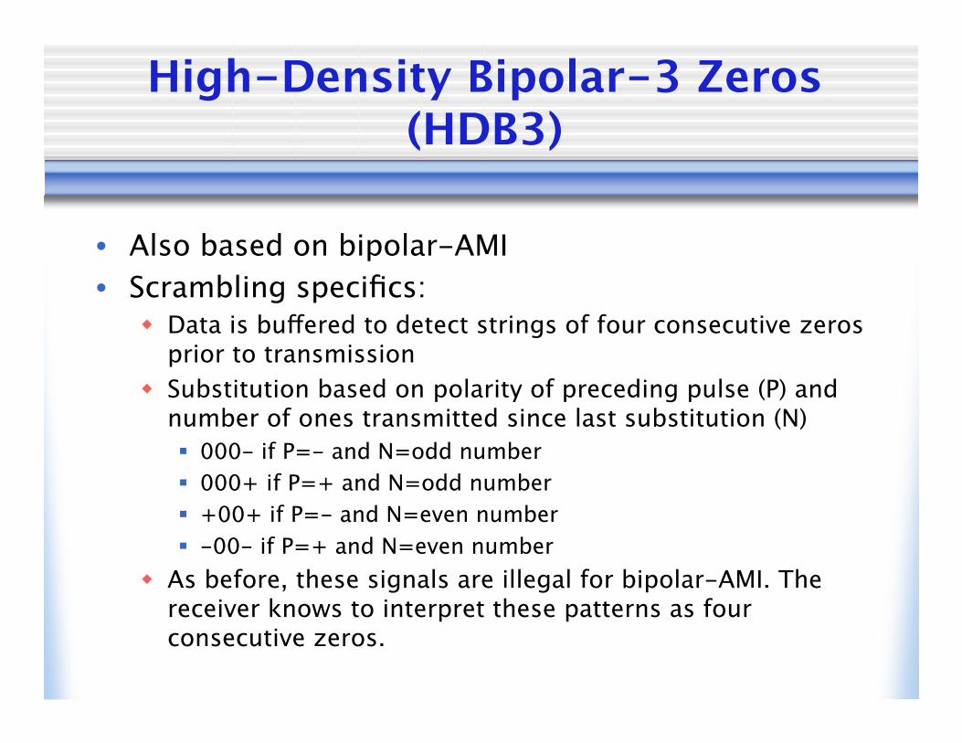
High-Density Bipolar-3 Zeros(HDB3)
• Also based on bipolar-AMI• Scrambling specifics:
Data is buffered to detect strings of four consecutive zerosprior to transmission
Substitution based on polarity of preceding pulse (P) andnumber of ones transmitted since last substitution (N) 000- if P=- and N=odd number 000+ if P=+ and N=odd number +00+ if P=- and N=even number -00- if P=+ and N=even number
As before, these signals are illegal for bipolar-AMI. Thereceiver knows to interpret these patterns as fourconsecutive zeros.

B8ZS and HDB3

Bandwidth picture
Spectrum Comparison