ecograph t, rsg35 - endress+hauser · record, visualize and monitor application the ecograph t...
TRANSCRIPT

Record, visualize and monitor
Application
The Ecograph T graphic display recorder records and visualizes relevant processvalues via analog or digital input signals. The measured values are securely saved andlimit values are monitored. Furthermore the Ecograph T offers intuitive operationand simple system integration. Remote configuration and visualization of the currentand recorded data is easy thanks to the integrated web server - no additionalsoftware needs to be installed. In addition the Essential Version of the Field DataManager software is also supplied with the product as standard. This software can beused to export the recorded data, save the data to an SQL database in a way that thedata cannot be manipulated, and visualize the data externally.
The Ecograph T is the right solution for a wide range of applications such as:• Quality and quantity monitoring in the water and wastewater industry• Monitoring of processes in power stations• Displaying and recording of critical process parameters• Tank and level monitoring• Temperature monitoring in metal working
Your benefits
• Versatile: up to 12 universal inputs record a wide range of measuring signals• Clear layout: 5.7" TFT screen for displaying measured values in a maximum of four
groups, with digital, bar graph and curve display• Fast: 100 ms scan rate for all channels• Compact: low installation depth, saves space and money• Easy: intuitive operation via the navigator (jog/shuttle dial) on site, or user-
friendly operation at the PC via the integrated web server• Safe: reliable data archiving with internal memory and separate SD card• Informative: e-mail notification in event of alarms and limit violation• System-enabled: common interfaces such as Ethernet, RS232/485, USB and
optional slave function for Modbus RTU/TCP• Smart: optional mathematics functions to calculate other values• WebDAV: data saved on SD card transmitted directly to a PC via HTTP without any
additional software.
Products Solutions Services
Technical InformationEcograph T, RSG35Universal Data Manager
TI01079R/09/EN/04.1671316325

Ecograph T, RSG35
2 Endress+Hauser
Function and system design
Measuring principle Electronic acquisition, display, recording, analysis, remote transmission and archiving of analog anddigital input signals.
The device is intended for installation in a panel or cabinet. There is also the option of operating it ina desktop housing or field housing.
Measuring system Multichannel data recording system with multicolored TFT display (145 mm / 5.7" screen size),galvanically isolated universal inputs (U, I, TC, RTD, pulse, frequency), digital inputs, transmitterpower supply, limit relay, communication interfaces (USB, Ethernet, optional RS232/485), optionallyavailable with Modbus protocol, 128 MB internal memory, external SD card and USB stick. AnEssential Version of the Field Data Manager software is included for SQL-supported data analysis atthe PC.
The number of inputs available in the basic device can be individually increased using amaximum of 3 plug-in cards. The device supplies power directly to connected two-wiretransmitters. The device is configured and operated via the navigator (jog/shuttle dial), via theintegrated web server and a PC, or via an external keyboard. Online help facilitates localoperation.
Reliability Dependability
Depending on the device version, the MTBF is between 52 years and 24 years (calculated based onSN29500 standard at 40°C)
Serviceability
Battery-backed time and data memory. It is advisable to have the backup battery replaced by aservice technician after 10 years.
Real time clock (RTC)
• Configurable summer/normal time changeover• Battery buffer. It is advisable to have the backup battery replaced by a service technician after 10
years.• Drift: <10 min./year• Time synchronization possible via SNTP or via digital input.
Standard diagnostic functions as per Namur NE 107
The diagnostic code is made up of the error category as per Namur NE 107 and the message number.
• Cable open circuit, short-circuit• Incorrect wiring• Internal device errors• Overrange/underrange detection• Ambient temperature out-of-range detection
Device error/alarm relay
One relay can be used as an alarm relay. If the device detects a system error (e.g. hardware defect) ora malfunction (e.g. cable open circuit), the selected output/relay switches.
This "alarm relay" switches if "F"-type errors occur (F = failure), i.e. "M"-type errors (M= Maintenancerequired) do not switch the alarm relay.
Safety
The tamper-proof recorded data are saved and can be transferred to an external SQL database forarchiving in a way that prevents subsequent manipulation.
IT security The manufacturer only provides a warranty if the device is installed and used as described in theOperating Instructions. The device is equipped with security mechanisms to protect it against anyinadvertent changes to the device settings.
IT security measures in line with operators' security standards and designed to provide additionalprotection for the device and device data transfer must be implemented by the operators themselves.

Ecograph T, RSG35
Endress+Hauser 3
Input
Measured values Number of analog universal inputs
Standard version without universal inputs. Optional input cards (slot 1-3) with 4 universal inputs(4/8/12) each.
Number of digital inputs
6 digital inputs
Number of mathematics channels
4 mathematics channels (optional). Mathematics functions can be freely edited via a formula editor.
Integration of calculated values e.g. for totalization.
Number of limit values
30 limit values (individual channel assignment)
Function of analog universal inputs
You are free to choose between the following measured variables for each universal input: U, I, RTD,TC, pulse input or frequency input.
Integration of input variable for totalization e.g. flow rate (m3/h) in quantity (m3).
Calculated values
The values of the universal inputs can be used to perform calculations in the mathematics channels.
Measuring range of analoguniversal inputs
According to IEC 60873-1: An additional display error of ±1 digit is permitted for every measuredvalue.
User-definable measuring ranges per universal input of the multifunction card:
Measuredvariable
Measuring range Maximum measured error ofmeasuring range (oMR),temperature drift
Inputresistance
Current (I) 0 to 20 mA; 0 to 20 mA quadratic0 to 5 mA4 to 20 mA; 4 to 20 mA quadratic±20 mAOverrange: up to 22 mA or -22 mA
±0.1% oMRTemperature drift: ±0.01%/K oMR
Load: 50 Ω±1 Ω
Voltage (U)>1 V
0 to 10 V; 0 to 10 V quadratic0 to 5 V1 to 5 V; 1 to 5 V quadratic±10 V±30 V
±0.1% oMRTemperature drift: ±0.01%/K oMR
≥1 MΩ
Voltage (U)≤1 V
0 to 1 V; 0 to 1 V quadratic±1 V±150 mV
±0.1% oMRTemperature drift: ±0.01%/K oMR
≥2.5 MΩ
Resistancethermometer(RTD)
Pt100: -200 to 850 °C (-328 to 1562 °F) (IEC 60751:2008, α=0.00385)Pt100: -200 to 510 °C (-328 to 950 °F) (JIS C 1604:1984, α=0.003916)Pt100: -200 to 850 °C (-328 to 1562 °F) (GOST 6651-94, α=0.00391)Pt500: -200 to 850 °C (-328 to 1562 °F) (IEC 60751:2008, α=0.00385)Pt500: -200 to 510 °C (-328 to 950 °F) (JIS C 1604:1984, α=0.003916)Pt1000: -200 to 600 °C (-328 to 1112 °F) (IEC 60751:2008, α=0.00385)Pt1000: -200 to 510 °C (-328 to 950 °F) (JIS C 1604:1984, α=0.003916)
4-wire: ±0.1% oMR3-wire: ±(0.1% oMR + 0.8 K)2-wire: ±(0.1% oMR + 1.5 K)Temperature drift: ±0.01%/K oMR
Cu50: -50 to 200 °C (-58 to 392 °F) (GOST 6651-94, α=4260)Cu50: -200 to 200 °C (-328 to 392 °F) (GOST 6651-94, α=4280)Pt50: -200 to 1100 °C (-328 to 2012 °F) (GOST 6651-94, α=0.00391)Cu100: -200 to 200 °C (-328 to 392 °F) (GOST 6651-94, α=4280)
4-wire: ±0.2% oMR3-wire: ±(0.2% oMR + 0.8 K)2-wire: ±(0.2% oMR + 1.5 K)Temperature drift: ±0.02%/K oMR

Ecograph T, RSG35
4 Endress+Hauser
Measuredvariable
Measuring range Maximum measured error ofmeasuring range (oMR),temperature drift
Inputresistance
Pt46: -200 to 1100 °C (-328 to 2012 °F) (GOST 6651-94, α=0.00391)Cu53: -200 to 200 °C (-328 to 392 °F) (GOST 6651-94, α=4280)
4-wire: ±0.3% oMR3-wire: ±(0.3% oMR + 0.8 K)2-wire: ±(0.3% oMR + 1.5 K)Temperature drift: ±0.02%/K oMR
Thermocouples (TC)
Type J (Fe-CuNi): -210 to 1200 °C (-346 to 2192 °F) (IEC 60584:2013)Type K (NiCr-Ni): -270 to 1300 °C (-454 to 2372 °F) (IEC 60584:2013)Type L (NiCr-CuNi): -200 to 800 °C (-328 to 1472 °F) (GOST R8.585:2001)Type L (Fe-CuNi): -200 to 900 °C (-328 to 1652 °F) (DIN 43710-1985)Type N (NiCrSi-NiSi): -270 to 1300 °C (-454 to 2372 °F) (IEC 60584:2013)Type T (Cu-CuNi): -270 to 400 °C (-454 to 752 °F) (IEC 60584:2013)
±0.1% oMR from -100 °C (-148 °F)±0.1% oMR from -130 °C (-202 °F)±0.1% oMR from -100 °C (-148 °F)±0.1% oMR from -100 °C (-148 °F)±0.1% oMR from -100 °C (-148 °F)±0.1% oMR from -200 °C (-328 °F)Temperature drift: ±0.01%/K oMR
≥1 MΩ
Type A (W5Re-W20Re): 0 to 2500 °C (32 to 4532 °F) (ASTME 988-96)Type B (Pt30Rh-Pt6Rh): 42 to 1820 °C (107.6 to 3308 °F) (IEC 60584:2013)Type C (W5Re-W26Re): 0 to 2315 °C (32 to 4199 °F) (ASTME 988-96)Type D (W3Re-W25Re): 0 to 2315 °C (32 to 4199 °F) (ASTME 988-96)Type R (Pt13Rh-Pt): -50 to 1768 °C (-58 to 3214 °F) (IEC 60584:2013)Type S (Pt10Rh-Pt): -50 to 1768 °C (-58 to 3214 °F) (IEC 60584:2013)
±0.15% oMR from 500 °C (932 °F)±0.15% oMR from 600 °C (1112 °F)±0.15% oMR from 500 °C (932 °F)±0.15% oMR from 500 °C (932 °F)±0.15% oMR from 100 °C (212 °F)±0.15% oMR from 100 °C (212 °F)Temperature drift: ±0.01%/K oMR
≥1 MΩ
Pulse input(I) 1)
Min. Pulse length 40 μs, max. 12.5 kHz; 0 to 7 mA = LOW; 13 to 20 mA = HIGH Load: 50 Ω±1 Ω
Frequencyinput (I) 1)
0 to 10 kHz, overrange: up to 12.5 kHz; 0 to 7 mA = LOW; 13 to 20 mA = HIGH ±0.02% @ f <100 Hz of reading±0.01% @ f ≥100 Hz of readingTemperature drift: 0.01% ofmeasured value over the entiretemperature range
1) If a universal input is used as a frequency or pulse input, a series resistor must be used in series connection with the voltage source. Example: 1.2kΩ series resistor at 24 V
Maximum load of inputs
Limit values for input voltage and current as well as cable open circuit detection/line influence/temperature compensation:
Measured variable Limit values (steady-state, withoutdestroying input)
Cable open circuit detection/line influence/temperature compensation
Current (I) Maximum permitted input voltage: 2.5 VMaximum permitted input current: 50 mA
4 to 20 mA range with disengageable cable open circuit monitoring to NAMURNE43. The following error ranges apply when NE43 is switched on:≤3.8 mA: underrange≥20.5 mA: overrange≤ 3.6 mA or ≥ 21.0 mA: open circuit (display shows: – – – –)
Pulse, frequency (I) Maximum permitted input voltage: 2.5 VMaximum permitted input current: 50 mA
No cable open circuit monitoring
Voltage (U) >1 V Maximum permitted input voltage: 35 V 1 to 5 V range with disengageable cable open circuit monitoring:<0.8 V or >5.2 V: cable open circuit (display shows: - - - -)
Voltage (U) ≤1 V Maximum permitted input voltage: 24 V
Resistancethermometer (RTD)
Measuring current: ≤1 mA Maximum barrier resistance (or line resistance):4-wire: max. 200 Ω; 3-wire: max. 40 ΩMaximum influence of barrier resistance (or line resistance) for Pt100, Pt500and Pt1000: 4-wire: 2 ppm/Ω, 3-wire: 20 ppm/ΩMaximum influence of barrier resistance (or line resistance) for Pt46, Pt50,Cu50, Cu53, Cu100 and Cu500: 4-wire: 6 ppm/Ω, 3-wire: 60 ppm/ΩCable open circuit monitoring if any connection is interrupted.
Thermocouples (TC) Maximum permitted input voltage: 24 V Influence of line resistance: <0.001%/ΩError, internal temperature compensation: ≤ 2 K
Scan rate
Current/voltage/pulse/frequency input: 100 ms per channel

Ecograph T, RSG35
Endress+Hauser 5
Thermocouples and resistance temperature detector: 1 s per channel
Data storage/save cycle
Selectable save cycle. Choose from: 1s / 2s / 3s / 4s / 5s / 10s / 15s / 20s / 30s / 1min / 2min /3min / 4min / 5min / 10min / 15min / 30min / 1h
Typical recording duration
Prerequisites for following tables:• No limit value violation / integration• Digital input not used• Signal analysis 1: off, 2: day, 3: month, 4: year• No active mathematics channels
Frequent entries in the event log reduce the memory availability!
128 MB internal memory:
Analog inputs Channels in groups Storage cycle (weeks, days, hours)
5 min 1 min 30 s 10 s 1 s
1 1/0/0/0 668, 4, 14 135, 0, 5 67, 4, 4 22, 3, 20 2, 1, 18
4 4/0/0/0 491, 0, 10 99, 4, 17 49, 6, 12 16, 4, 15 1, 4, 16
8 4/4/0/0 246, 1, 14 49, 6, 1 24, 6, 19 8, 2, 7 0, 5, 20
12 4/4/4/0 164, 2, 4 33, 1, 18 16, 4, 13 5, 3, 21 0, 3, 21
External memory, 1 GB SD card:
Analog inputs Channels in groups Storage cycle (weeks, days, hours)
5 min 1 min 30 s 10 s 1 s
1 1/0/0/0 12825, 5, 20 2580, 4, 18 1291, 2, 5 430, 4, 14 43, 0, 12
4 4/0/0/0 8672, 5, 12 1749, 6, 13 875, 6, 13 292, 1, 8 29, 1, 14
8 4/4/0/0 4343, 1, 1 875, 1, 17 438, 0, 6 146, 0, 17 14, 4, 7
12 4/4/4/0 2896, 6, 13 583, 3, 21 292, 0, 6 97, 2, 20 9, 5, 4
Converter resolution
24 bit
Totalization
The interim, daily, monthly and yearly value and the total value can be determined (13-digit, 64 bit).
Analysis
Recording of quantity/operating time (standard function), also a min/max/median analysis withinthe set time frame.
Digital inputs Input level To IEC 61131-2: logical “0" (corresponds to -3 to +5 V), activation with logical "1"(corresponds to +12 to +30 V)
Input frequency max. 25 Hz
Pulse length Min. 20 ms (pulse counter)
Pulse length Min. 100 ms (control input, messages, operating time)
Input current max. 2 mA
Input voltage Max. 30 V
Ecograph T, RSG35
6 Endress+Hauser
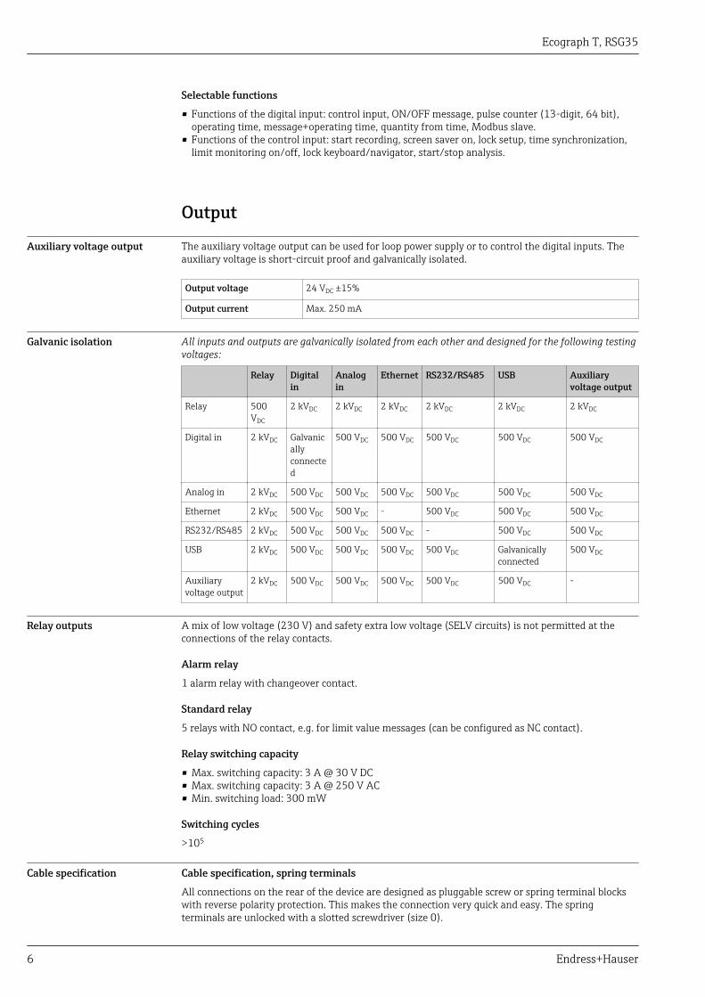
Selectable functions
• Functions of the digital input: control input, ON/OFF message, pulse counter (13-digit, 64 bit),operating time, message+operating time, quantity from time, Modbus slave.
• Functions of the control input: start recording, screen saver on, lock setup, time synchronization,limit monitoring on/off, lock keyboard/navigator, start/stop analysis.
Output
Auxiliary voltage output The auxiliary voltage output can be used for loop power supply or to control the digital inputs. Theauxiliary voltage is short-circuit proof and galvanically isolated.
Output voltage 24 VDC ±15%
Output current Max. 250 mA
Galvanic isolation All inputs and outputs are galvanically isolated from each other and designed for the following testingvoltages:
Relay Digitalin
Analogin
Ethernet RS232/RS485 USB Auxiliaryvoltage output
Relay 500VDC
2 kVDC 2 kVDC 2 kVDC 2 kVDC 2 kVDC 2 kVDC
Digital in 2 kVDC Galvanicallyconnected
500 VDC 500 VDC 500 VDC 500 VDC 500 VDC
Analog in 2 kVDC 500 VDC 500 VDC 500 VDC 500 VDC 500 VDC 500 VDC
Ethernet 2 kVDC 500 VDC 500 VDC - 500 VDC 500 VDC 500 VDC
RS232/RS485 2 kVDC 500 VDC 500 VDC 500 VDC - 500 VDC 500 VDC
USB 2 kVDC 500 VDC 500 VDC 500 VDC 500 VDC Galvanicallyconnected
500 VDC
Auxiliaryvoltage output
2 kVDC 500 VDC 500 VDC 500 VDC 500 VDC 500 VDC -
Relay outputs A mix of low voltage (230 V) and safety extra low voltage (SELV circuits) is not permitted at theconnections of the relay contacts.
Alarm relay
1 alarm relay with changeover contact.
Standard relay
5 relays with NO contact, e.g. for limit value messages (can be configured as NC contact).
Relay switching capacity
• Max. switching capacity: 3 A @ 30 V DC• Max. switching capacity: 3 A @ 250 V AC• Min. switching load: 300 mW
Switching cycles
>105
Cable specification Cable specification, spring terminals
All connections on the rear of the device are designed as pluggable screw or spring terminal blockswith reverse polarity protection. This makes the connection very quick and easy. The springterminals are unlocked with a slotted screwdriver (size 0).

Ecograph T, RSG35
Endress+Hauser 7
Please note the following when connecting:• Wire cross-section, auxiliary voltage output, digital I/O and analog I/O: max. 1.5 mm2 (14 AWG)
(spring terminals)• Wire cross-section, mains: max. 2.5 mm2 (13 AWG) (screw terminals)• Wire cross-section, relays: max. 2.5 mm2 (13 AWG) (spring terminals)• Stripping length: 10 mm (0.39 in)
No ferrules must be used when connecting flexible wires to spring terminals.
Shielding and grounding
Optimum electromagnetic compatibility (EMC) can only be guaranteed if the system componentsand, in particular, the lines - both sensor lines and communication lines - are shielded and the shieldforms as complete a cover as possible. A shielded line must be used for sensor lines that are longerthan 30 m. A shield coverage of 90% is ideal. In addition, make sure not to cross sensor lines andcommunication lines when routing them. Connect the shield as often as possible to the referenceground to ensure optimum EMC protection for the different communication protocols and theconnected sensors.
To comply with requirements, three different types of shielding are possible:• Shielding at both ends• Shielding at one end on the supply side with capacitance termination at the device• Shielding at one end on the supply sideExperience shows that the best results with regard to EMC are achieved in most cases in installationswith one-sided shielding on the supply side (without capacitance termination at the device).Appropriate internal device wiring measures must be taken to allow unrestricted operation whenEMC interference is present. These measures have been taken into account for this device. Operationin the event of disturbance variables as per NAMUR NE21 is thus guaranteed.
Where applicable, national installation regulations and guidelines must be observed during theinstallation! Where there are large differences in potential between the individual grounding points,only one point of the shielding is connected directly with the reference ground.
If the shielding of the cable is grounded at more than one point in systems without potentialmatching, mains frequency equalizing currents can occur. These can damage the signal cable orsignificantly impact signal transmission. In such cases the shielding of the signal cable is to begrounded on one side only, i.e. it may not be connected to the ground terminal of the housing.The shield that is not connected should be insulated!

Ecograph T, RSG35
8 Endress+Hauser
Power supply
Terminal assignment
5
6 9
1
Fre
qu
en
cy
A0019304
1 Terminals on back of device
Supply voltage • Extra-low voltage power supply unit ±24 V AC/DC (-10% / +15%) 50/60Hz• Low voltage power supply unit 100 to 230 V AC (±10%) 50/60Hz
An overload protection element (rated current ≤ 10 A) is required for the power cable.
Power consumption • 100 to 230 V: max. 35 VA• 24 V: max. 24 VAThe power actually consumed depends on the individual operating state and the device version (LPS,USB, brightness of screen, number of channels, etc). The active power here is approx. 3 W to 20 W.
Power supply failure Battery-backed time and data memory. The device starts automatically following a power failure.
Electrical connection Supply voltage
Power unit type Terminal
A0019103
100-230 VAC L+ N- PE
Phase L Zero conductor N Ground
24 V AC/DC L+ N- PE
Phase L or + Zero conductor N or - Ground

Ecograph T, RSG35
Endress+Hauser 9
Relay
Type Terminal (max. 250 V, 3 A)
A0019103
Alarm relay 1 R11 R12 R13
Changeovercontact
Normallyclosed contact(NC) 1)
Normally opencontact (NO) 2)
Relay 2 to 6 Rx1 Rx2
Switching contact Normally opencontact (NO 2))
1) NC = normally closed (breaker)2) NO = normally open (maker)
Digital inputs; auxiliary voltage output
Type Terminal
A0019103
Digital input1 to 6
D11 to D61 GND1
Digital input 1 to 6(+)
Ground (-) for digitalinputs 1 to 6
Auxiliaryvoltageoutput, notstabilized,max. 250mA
24V Out - 24V Out +
- Ground + 24V (±15%)
Analog inputs
The first digit (x) of the two-digit terminal number corresponds to the associated channel:
Type Terminal
Ch
x
x1
x2
x3
x4
x5
x6
A0019303
x1 x2 x3 x4 x5 x6
Current/pulse/frequencyinput 1)
(+) (-)
Voltage > 1V (+) (-)
Voltage ≤ 1V (+) (-)
Resistance thermometerRTD (2-wire)
(A) (B)
Ecograph T, RSG35
10 Endress+Hauser
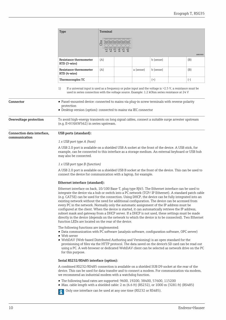
Type Terminal
Ch
x
x1
x2
x3
x4
x5
x6
A0019303
Resistance thermometerRTD (3-wire)
(A) b (sense) (B)
Resistance thermometerRTD (4-wire)
(A) a (sense) b (sense) (B)
Thermocouples TC (+) (-)
1) If a universal input is used as a frequency or pulse input and the voltage is >2.5 V, a resistance must beused in series connection with the voltage source. Example: 1.2 kOhm series resistance at 24 V
Connector • Panel-mounted device: connected to mains via plug-in screw terminals with reverse polarityprotection
• Desktop version (option): connected to mains via IEC connector
Overvoltage protection To avoid high-energy transients on long signal cables, connect a suitable surge arrester upstream(e.g. E+H HAW562) in series upstream.
Connection data interface,communication
USB ports (standard):
1 x USB port type A (host)
A USB 2.0 port is available on a shielded USB A socket at the front of the device. A USB stick, forexample, can be connected to this interface as a storage medium. An external keyboard or USB hubmay also be connected.
1 x USB port type B (function)
A USB 2.0 port is available on a shielded USB B socket at the front of the device. This can be used toconnect the device for communication with a laptop, for example.
Ethernet interface (standard):
Ethernet interface on back, 10/100 Base-T, plug type RJ45. The Ethernet interface can be used tointegrate the device via a hub or switch into a PC network (TCP/ IP Ethernet). A standard patch cable(e.g. CAT5E) can be used for the connection. Using DHCP, the device can be fully integrated into anexisting network without the need for additional configuration. The device can be accessed fromevery PC in the network. Normally only the automatic assignment of the IP address must beconfigured at the client. When the device is started, it can automatically retrieve the IP address,subnet mask and gateway from a DHCP server. If a DHCP is not used, these settings must be madedirectly in the device (depends on the network to which the device is to be connected). Two Ethernetfunction LEDs are located on the rear of the device.
The following functions are implemented:• Data communication with PC software (analysis software, configuration software, OPC server)• Web server• WebDAV (Web-based Distributed Authoring and Versioning) is an open standard for the
provisioning of files via the HTTP protocol. The data saved on the device's SD card can be read outusing a PC. A web browser or dedicated WebDAV client can be selected as network drive on the PCfor this purpose.
Serial RS232/RS485 interface (option):
A combined RS232/RS485 connection is available on a shielded SUB D9 socket at the rear of thedevice. This can be used for data transfer and to connect a modem. For communication via modem,we recommend an industrial modem with a watchdog function.
• The following baud rates are supported: 9600, 19200, 38400, 57600, 115200• Max. cable length with a shielded cable: 2 m (6.6 ft) (RS232), or 1000 m (3281 ft) (RS485)
Only one interface can be used at any one time (RS232 or RS485).

Ecograph T, RSG35
Endress+Hauser 11
Performance characteristics
Response time Input Output Time [ms]
Current, voltage, pulse Relay ≤ 550
RTD Relay ≤ 1150
TC 1) Relay ≤ 1550
Cable open circuit detection, current input Relay ≤ 1150
Sensor error RTD, TC Relay ≤ 5000
Digital input Relay ≤ 350
1) If internal measuring point temperature compensation is used, otherwise values as for voltage
Reference operatingconditions
Reference temperature 25 °C (77 °F) ±5 K
Warm-up period 120 min.
Humidity 20 to 60 % rel. humidity
Hysteresis Can be configured for limit values in the setup
Long-term drift As per IEC 61298-2: max. ±0.1%/year (of measuring range)
Installation
Mounting location andinstallation dimensions
The device is designed for use in a panel in non-hazardous areas.

Ecograph T, RSG35
12 Endress+Hauser
144 (5.67)
14
4 (
5.6
7)
14
1 (
5.5
5)
17
(0
.67
)3
4
(1.3
4)
X
Y
A0019301
2 Panel mounting and dimensions in mm (in)
Please observe the installation depth of approx. 158 mm (6.22 in) for the device incl. terminals andfastening clips.
• Panel cutout: 138 to 139 mm (5.43 to 5.47 in) x 138 to 139 mm (5.43 to 5.47 in)• Panel strength: 2 to 40 mm (0.08 to 1.58 in)• Angle of vision: from the midpoint axis of the display, 75° to the left and right, 65° above and
below.• A minimum distance of 15 mm (0.59 in) mm (inch) between the devices must be observed if
aligning the devices in the Y-direction (vertically above one another). A minimum distance of10 mm (0.39 in) mm (inch) between the devices must be observed if aligning the devices in the X-direction (horizontally beside one another).
• Securing to DIN 43 834
Field housing assembly anddesign (optional)
As an option, the device can be ordered ready-mounted in a field housing with IP65.
Dimensions (B x H x D) approx.: 320 mm (12.6 in) x 320 mm (12.6 in) x 254 mm (10 in)
Desktop housing assemblyand design (optional)
As an option, the device can be ordered ready-mounted in a desktop housing.
Dimensions (B x H x D) approx.: 293 mm (11.5 in) x 188 mm (7.4 in) x 211 mm (8.3 in)(dimensions with bracket, feet and installed device)
Environment
Ambient temperature range –10 to +50 °C (14 to 122 °F)

Ecograph T, RSG35
Endress+Hauser 13
Storage temperature –20 to +60 °C (–4 to +140 °F)
Humidity 5 to 85 %, not condensating
Climate class To IEC 60654-1: Class B2
Electrical safety Class I equipment, overvoltage category II
Pollution level 2
Altitude < 2 000 m (6 561 ft) above MSL
Degree of protection Front IP65 / NEMA 4 (not assessed by UL)
Rear IP20
Electromagneticcompatibility
EMC to all relevant requirements of the IEC/EN 61326- series and NAMUR NE21. For details seedeclaration of conformity.
• Interference immunity: as per IEC/EN 61326 series (industrial environment) / NAMUR NE21Maximum measured error <1% of measuring range
• Interference emissions: as per IEC 61326-1 Class A
Mechanical construction
Design, dimensions Information about design and dimensions → 11
Weight • Panel-mounted device with maximum configuration: approx. 2.2 kg (4.85 lbs)• Desktop housing (excluding device): approx. 2.3 kg (5 lbs)• Field housing (excluding device): approx. 4 kg (8.8 lbs)
Materials Front frame Zinc die cast GD-Z410, powder-coated
Sight glass Transparent Makrolon plastic (FR clear 099) UL94-V2
Flap; jog/shuttle dial Plastic ABS UL94-V2
Mounting guide rail for PCBs; motherboard fixing unit;display retainer plate
Plastic PA6-GF15 UL94-V2
Seal to panel wall; seal to display; seal in flap; seal tonavigator
Rubber EPDM 70 Shore A
Casing; rear panel Galvanized sheet steel St 12 ZE
All materials are silicone-free.
Materials of desktop housing
• Housing half-panels: sheet steel, electrolytically plated (powder-coated)• Side sections: aluminum extruded section (powder-coated)• Section ends: colored polyamide
Display and operating elements
Operating concept The device can be operated directly onsite, or via remote configuration with the PC via interfaces andoperating tools (Web server, configuration software).

Ecograph T, RSG35
14 Endress+Hauser
Integrated operating instructionsThe device's simple control system enables you to perform commissioning for many applicationswithout the need for hardcopy operating instructions. The device has an integrated help functionand displays operating instructions directly on screen if the navigator (jog/shuttle dial) is pressed forlonger than 3 seconds.
Local operation Operating elements
6 4 3 2 15
7
8
9
10 11
12
A0020602-EN
3 Front of device with open flap
ItemNo.
Operating function (display mode = display of measured values)(Setup mode = operating in the Setup menu)
1 "Navigator": jog/shuttle dial for operating with additional press/hold function.In display mode: turn the dial to switch between the various signal groups. Press the dial to display themain menu.In setup mode or in a selection menu: turn the dial counterclockwise to move the bar or the cursorupwards or to the left, changes the parameter. Turning clockwise moves the bar or cursor down orclockwise, changes parameter.
2 LED at SD slot. Orange LED lights up or flashes when the device writes to or reads from the SD card.Do not remove the SD card if the LED is lit or flashing! Risk of data loss!
3 Slot for SD card
4 USB B socket "Function" e.g. to connect to PC or laptop
5 Green LED lit: power supply present
6 USB A socket "Host" e.g. for USB memory stick or external keyboard
7 In display mode: alternating status display (e.g. set zoom range) of the analog or digital inputs in theappropriate color of the channel.In setup mode: different information can be displayed here depending on the display type.
8 In display mode: window for measured value display (e.g. curve display).In setup mode: display of operating menu
9 In display mode: current group name, type of evaluationIn setup mode: name of the current operating item (dialog title)
10 In display mode: displays current date/timeIn setup mode: --

Ecograph T, RSG35
Endress+Hauser 15
ItemNo.
Operating function (display mode = display of measured values)(Setup mode = operating in the Setup menu)
11 In display mode: alternating display indicating the percentage space on the SD card or USB stick thathas already been used.Status symbols are also displayed in alternation with the memory information.In setup mode: the current "direct access" operating code is displayed
12 In display mode: display of current measured values and the status in the event of an error/alarmcondition. In the case of counters, the type of counter is displayed as a symbol.
If a measuring point has limit value status, the corresponding channel identifier is highlightedin red (quick detection of limit value violations). During a limit value violation and deviceoperation, the acquisition of measured values continues uninterrupted.
Languages The following languages can be selected in the operating menu: German, English, Spanish, French,Italian, Dutch, Swedish, Polish, Portuguese, Czech, Russian, Japanese, Chinese (Traditional), Chinese(Simplified)
Remote operation Device access via operating tools
Device configuration and measured value retrieval can also be done via interfaces. The followingoperating tools are available for this purpose:
Operating tool Functions Access via
"Field Data Manager(FDM)" analysissoftware, SQLdatabase support(included in thedelivery)
• Export of saved data (measured values, analyses, event log)• Visualization and processing of saved data (measured
values, analyses, event log)• Safe archiving of exported data in a SQL database
RS232/RS485, USB,Ethernet
Web server(integrated into thedevice; access viabrowser)
• Display of current and historical data and measured valuecurves via the web browser
• Easy configuration without additional installed software• Remote access to device and diagnostic information
Ethernet
OPC server(optional)
The following momentary values can be provided:• Analog channels• Digital channels• Mathematics• Totalizer
RS232/RS485, USB,Ethernet
"FieldCare/DeviceCare"configurationsoftware (includedin the delivery)
• Device configuration• Loading and saving device data (upload/download)• Documentation of the measuring point
USB, Ethernet
System integration The device has (optional) fieldbus interfaces for exporting process values. Measured values andstatuses can also be transmitted to the device via fieldbus. Alarms or errors in the context of datatransmission are displayed depending on the bus system (e.g. status byte). The process values aretransferred in the same devices that are used for display at the device.
Ethernet
The following functions are implemented:• Data communication with PC software (analysis software, configuration software, OPC server)• Web server
Modbus RTU/TCP slave
The device can be connected to a Modbus system via RS485 or Ethernet interface. Up to 12 analoginputs and 6 digital inputs can be transmitted via Modbus and stored in the device.
Ecograph T, RSG35
16 Endress+Hauser
Certificates and approvals
CE mark The measuring system meets the legal requirements of the applicable EC guidelines. These are listedin the corresponding EC Declaration of Conformity together with the standards applied. Endress+Hauser confirms successful testing of the device by affixing to it the CE mark.
UL approval UL recognized component (see www.ul.com/database, search for Keyword "E225237")
CSA The product meets the requirements as per "CLASS 2252 05 - Process Control Equipment"
Other standards andguidelines
• IEC 60529:Degree of protection provided by housing (IP code)
• IEC/EN 61010-1:Safety requirements for electrical equipment for measurement, control and laboratory use
• IEC/EN 61326 Series:Electromagnetic compatibility (EMC requirements)
Ordering information
Ordering information Detailed ordering information is available from the following sources:• In the Product Configurator on the Endress+Hauser website: www.endress.com -> Click "Corporate"
-> Select your country -> Click "Products" -> Select the product using the filters and search field ->Open product page -> The "Configure" button to the right of the product image opens the ProductConfigurator.
• From your Endress+Hauser Sales Center: www.addresses.endress.comProduct Configurator - the tool for individual product configuration• Up-to-the-minute configuration data• Depending on the device: Direct input of measuring point-specific information such as
measuring range or operating language• Automatic verification of exclusion criteria• Automatic creation of the order code and its breakdown in PDF or Excel output format• Ability to order directly in the Endress+Hauser Online Shop
Scope of delivery The scope of delivery of the device comprises:• Device (with terminals, as per order)• 2 fastening clips• USB cable• Optional: Industrial grade SD card (card is located in the SD slot behind the flap on the front of the
housing)• "Field Data Manager (FDM)" analysis software on DVD (Essential, Demo or Professional version,
depending on order)• "FieldCare Device Setup / DeviceCare" configuration software on DVD• Delivery note• Multilanguage Brief Operating Instructions, hard copy

Ecograph T, RSG35
Endress+Hauser 17
AccessoriesVarious accessories, which can be ordered with the device or subsequently from Endress+Hauser, areavailable for the device. Detailed information on the order code in question is available from yourlocal Endress+Hauser sales center or on the product page of the Endress+Hauser website:www.endress.com.
Device-specific accessories Description Order No.
"Industrial Grade" SD card, industry standard, 1GB 71213190
Field Data Manager analysis software with SQL database support (1 x workstationlicense, Professional version)
MS20-A1
OPC server software (full version on CD) RXO20-11
Description Order No.
Accessories for RXU10 data manager RXU10- _ _
Designation:Cable set RS232 for connection to PC or modemUSB - RS232 converterCable USB-A - USB-B, 1.8 m (5.9 ft)Configuration software "FieldCare Device Setup" + USB cable
RXU10-B _RXU10-E _RXU10-F _RXU10-G _
Field housing IP65
32
0 (
12
.6)
320 (12.6)
25
4 (
10
)
A0021773
4 Dimensions in mm (in)
RXU10-H _

Ecograph T, RSG35
18 Endress+Hauser
Description Order No.
Desktop housing, cable with Schuko plugDesktop housing, cable with US plugDesktop housing, cable with Swiss plug
293.4 (11.55)
236 (9.29)
17
3 (
6.8
1)
18
8 (
7.4
)
184 (7,24)
207.57 (8.17)
A0021772
5 Dimensions in mm (in)
RXU10-I _RXU10-J _RXU10-K _
Version:StandardNeutral
RXU10- _ 1RXU10- _ 2


www.addresses.endress.com