ecu ms 5.5 manual - bosch motorsport€¦ · 2 / 38 ecu ms 5.5 bosch motorsport. getting started...
TRANSCRIPT
ECU MS 5.5
Manual
F 02U 002 550-02 4/4/2017
Table of contents
1 Getting started ..................................................................................................................................................... 3
2 MS 5: FPGA plus PowerPC .................................................................................................................................. 4
3 Technical Data ...................................................................................................................................................... 53.1 ECU plus Datalogger ...................................................................................................................................................................... 83.2 Input Channels ................................................................................................................................................................................. 83.3 Output Channels .............................................................................................................................................................................. 93.4 Power Supply .................................................................................................................................................................................... 93.5 Ignition Trigger Wheel ................................................................................................................................................................ 113.6 Sensor Recommendation Clubsport ...................................................................................................................................... 133.7 Sensor Recommendation High-End ...................................................................................................................................... 14
4 Starting up the ECU ........................................................................................................................................... 154.1 Initial Data Application ................................................................................................................................................................ 154.2 Peripherals ....................................................................................................................................................................................... 214.3 Vehicle Test ...................................................................................................................................................................................... 23
5 Data logging ...................................................................................................................................................... 255.1 Software ............................................................................................................................................................................................ 255.2 Starting up the data logging .................................................................................................................................................... 255.3 Welcome to RaceCon .................................................................................................................................................................. 255.4 Welcome to WinDarab ................................................................................................................................................................ 31
6 Extensibility ........................................................................................................................................................ 35
7 Appendices ......................................................................................................................................................... 36
Table of Contents
2 / 38 ECU MS 5.5 Bosch Motorsport
Getting startedDisclaimerDue to continuous enhancements we reserve the rights to change any illustra-tions, photos and technical data within this manual. Please retain this manual foryour records.
Before startingBefore starting your engine for the first time, install the complete software. BoschMotorsport software is developed for Windows operation systems. Read themanual carefully and follow the application hints step by step. Don’t hesitate tocontact us. Contact data can be found on the backside of this document.
Caution Risk of injury if using the MS 5.5 inappropriately.Use the MS 5.5 only a intended in this manual. Any maintenance or repair mustbe performed by authorized and qualified personnel approved by Bosch Motor-sport.
Caution Risk of injury if using the MS 5.5 with uncertified combinationsand accessories.Operation of the MS 5.5 is only certified with the combinations and accessoriesthat are specified in this manual. The use of variant combinations, accessoriesand other devices outside the scope of this manual are only permitted when theyhave been determined to be compliant from a performance and safety stand-point by a representative from Bosch Motorsport.
Notice The Bosch Motorsport MS 5.5 was developed for use by professionals and re-quires in depth knowledge of automobile technology and experience in motor-sport. Using the system does not come without its risks.
It is the duty of the customer to use the system for motor racing purposes onlyand not on public roads. We accept no responsibility for the reliability of the sys-tem on public roads. In the event that the system is used on public roads, weshall not be held responsible or liable for damages.
Notice Drive-by-wire systemsFor systems with drive-by-wire additional safety provisions apply. For detailsplease refer to the document „Safety Instructions for Drive-by-Wire Systems inMotorsport Applications“.
1
Getting started | 1
Bosch Motorsport ECU MS 5.5 3 / 38
MS 5: FPGA plus PowerPCA field-programmable gate array (FPGA) is a semiconductor device containingcomponents called "logic blocks", and programmable interconnects. Logic blockscan be programmed to perform the function of basic logic gates such as ANDand XOR, or more complex combinational functions such as decoders or mathe-matical functions. In most FPGAs, the logic blocks also include memory elements,which may be simple or more complete blocks of memory.
A hierarchy of programmable interconnects allows logic blocks to be intercon-nected as needed by the system designer, somewhat like a one-chip program-mable breadboard. Logic blocks and interconnects can be programmed by thecustomer or designer, after the FPGA is manufactured, to implement any logicalfunction - hence the name "field-programmable".
With our first FPGA-based ECU family Motronic MS 5 we offer you the possibilityto integrate individual designed functions. The systems flexibility allows the sup-port of any unusual engine configuration or chassis functionality.
In combination with a very powerful PowerPC Freescale MPC 5200B that allowssynchronized calculator operations, the MS 5 family typifies the state of the art inECU design.
2
2 | MS 5: FPGA plus PowerPC
4 / 38 ECU MS 5.5 Bosch Motorsport
Technical Data
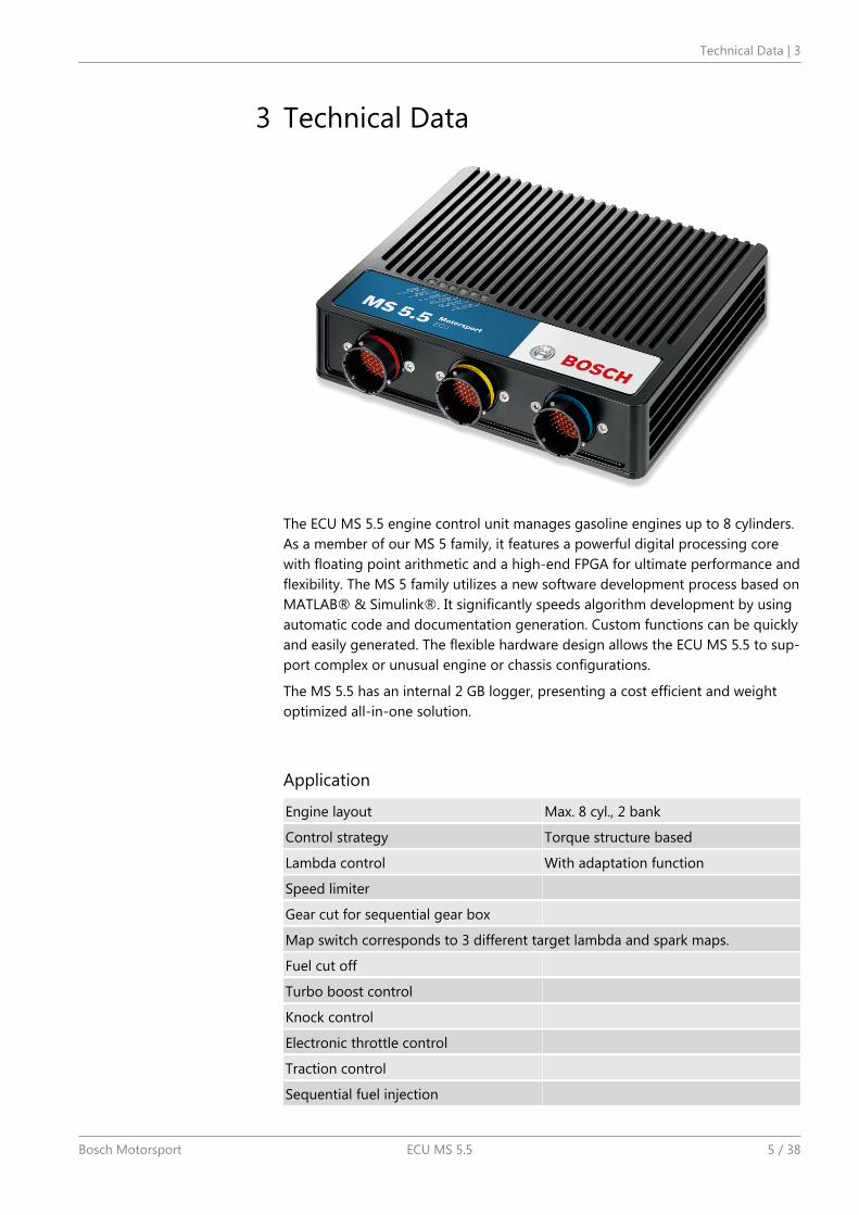
The ECU MS 5.5 engine control unit manages gasoline engines up to 8 cylinders.As a member of our MS 5 family, it features a powerful digital processing corewith floating point arithmetic and a high-end FPGA for ultimate performance andflexibility. The MS 5 family utilizes a new software development process based onMATLAB® & Simulink®. It significantly speeds algorithm development by usingautomatic code and documentation generation. Custom functions can be quicklyand easily generated. The flexible hardware design allows the ECU MS 5.5 to sup-port complex or unusual engine or chassis configurations.
The MS 5.5 has an internal 2 GB logger, presenting a cost efficient and weightoptimized all-in-one solution.
Application
Engine layout Max. 8 cyl., 2 bank
Control strategy Torque structure based
Lambda control With adaptation function
Speed limiter
Gear cut for sequential gear box
Map switch corresponds to 3 different target lambda and spark maps.
Fuel cut off
Turbo boost control
Knock control
Electronic throttle control
Traction control
Sequential fuel injection
3
Technical Data | 3
Bosch Motorsport ECU MS 5.5 5 / 38
Asymmetric injection timing Optional
Asymmetric ignition timing Optional
Calibration interface CCP via CAN or XCP via Ethernet
Interface to Bosch Data Logging System
Internal data logger 2 GB
Max. Vibration Vibration Profile 1 see www.bosch-motorsport.com
Technical Specifications
Mechanical Data
Aluminum housing
3 high pin density motorsport connectors
165 pins, each pin individually filtered
Vibration suppression via multipoint fixed circuit boards
Size 180 x 155 x 40 mm
Weight 1,270 g
Protection Classification IP67 to DIN 40050, Section 9, Is-sue 2008
Temp. range (at internal sensors) -20 to 85°C
Electrical Data
Power consumption. (w/o loads) Approx. 13 W at 14 V
Power supply
Operating range 6.5 to 18 V
Recommended 11 to 14 V
Absolute maximum 6 to 24 V
Inputs
2 thermocouple exhaust gas temperature sensors
2 lambda interfaces (LSU 4.9)
1 crankshaft sensor (2-wire, inductive or Hall-effect)
1 camshaft sensor (2-wire, inductive or Hall-effect)
2 turbo speed sensors (2-wire, inductive or Hall-effect)
4 wheel speed sensors (inductive or Hall-effect)
38 universal analog inputs 0 to 5 V, 12 Bit
4 analog inputs (angle synchronous or time synchronous triggering up to 250ksps, 12 Bit)
4 inputs for vibration knock sensors
1 lap trigger input
Outputs
8 injection power stages (peak & hold)
8 ignition power stages (up to 20 A)
3 | Technical Data
6 / 38 ECU MS 5.5 Bosch Motorsport

20 power stages (2 A; low side; PWM)
4 power stages (4 A; low side; PWM)
2 H-bridges (5 A)
3 sensor supplies 5 V/400 mA
1 sensor supply 10 V/100 mA
1 protected Ubat output 1 A
6 diagnostic outputs with selectable internal signals
1 time base reference synch-in/out
Communication
2 x 100 Mbps Ethernet interfaces
1 x RS232 serial interface
3 x 1 Mbps CAN interfaces
1 x LIN interface
Installation Notes
Internal battery for data preservation included.
Required service interval 12 months (internal battery is replaced).
Depending on your experiences with calibration of ECUs we recommend calibra-tion support from Bosch Motorsport.
Please remember that the mating connectors and the programming interfaceMSA-Box II are not included and must be ordered separately.
Ordering Information
ECU MS 5.5 F 02U V00 285-04
Software
Modas Sport Calibration Software Inclusive
Environment (not included)
Programming interface MSA-Box II F 02U V00 327-02
Data logger C 60 F 02U V00 875-02
Display DDU 8 F 02U V00 873-05
Connectors (not included)
AS 6-16-35 SA (yellow) F 02U 000 467-01
AS 6-16-35 SB (blue) F 02U 000 468-01
AS 6-16-35 SN (red) F 02U 000 466-01
Technical Data | 3
Bosch Motorsport ECU MS 5.5 7 / 38
ECU plus DataloggerThe ECU MS 5.5 combines an ECU and a datalogger in a common housing. Dueto this reason, some external communication interfaces are shared betweenthose two components:
1. EthernetThe MS 5.5 features an internal ethernet-switch which interconnects the twoexternal interfaces, the logger-part and the ECU-part of the MS 5.5. Thereforeboth, the ECU and the datalogger can be accessed using any of the two ex-ternal ethernet interfaces.
2. CANThe internal ECU features 3 CAN interfaces (CAN1, CAN2, CAN3), the loggerfeatures 2 CAN interfaces (CAN1, CAN2). These interfaces are connected in-ternally as given below:
External Pin ECU Datalogger
CAN1 CAN1 CAN1
CAN2 CAN2 CAN2
CAN3 CAN3
Due to the internal interconnection of logger-CAN1 and ECU-CAN1 resp. logger-CAN2 and ECU-CAN2 the CAN bus speeds must be configured identically oneach common CAN-bus (Default CAN speed is 1 Mbaud). E.g. if ECU-CAN1 isconfigured to a bus speed of 500 kBaud, the datalogger configuration of CAN1must be set to 500 kBaud as well (using "RaceCon"-configuration tool).
Input ChannelsThere are several inputs for temperature measurements e.g. engine temperaturetmot or intake air temperature tair. Temperature inputs have an internal “pull up”resistor for use with a NTC sensor (negative temp. coefficient). These pull ups canbe switched software specifically. Depending on the used sensor (e.g. 15 KOhmor 2.5 KOhm NTC) the corresponding linearization curve has to fit. For measuringof accelerator pedal position or pressures, e.g. fuel pressure pfuel or oil pressurepoil, which deliver a voltage (active sensors), pull up resistors are not allowed.These sensors must be calibrated with the sensors offset and sensitivity values(printed on the sensor, if it is from Bosch).
In the default configuration the ECU MS 5.5 needs an inductive speed sensor onthe ignition trigger wheel. For the camshaft signal a Hall-effect sensor is necessa-ry. Also for wheel speed measurement Hall-effect sensors are recommended.Four Hall-effect wheel speed sensors can be connected directly to the ECU. Dif-ferent hardware configurations are available on request.
For wide range Lambda measurement and control the Lambda sensor Bosch LSU4.9 is used.
3.1
3.2
3 | Technical Data
8 / 38 ECU MS 5.5 Bosch Motorsport
Output ChannelsThe ECU MS 5.5 has 8 independent injection power stages. These output driverscan deliver a maximum current of 2.2 Ampere. Therefore the injection valvesmust have at least 6 Ohm internal resistance.
The 8 internal ignition power stages are able to drive high current ignition coils.
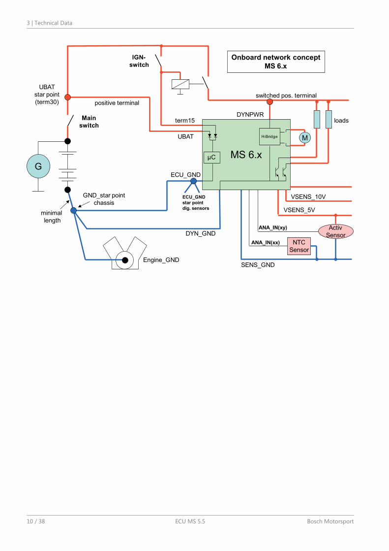
Power SupplyPlease ensure that you have a good ground installation. That means:
A ground that has a solid, low resistance connection to the battery minus ter-minal.
Connection should be free from dirt, grease, paint, anodizing, etc.
Use large diameter wire.
More metal-to-metal contact is better
Connection of the power supplyThe following notations for power signals are used:
Term 15 is a switched battery rail controlled by the IGN-switch.
Term 30 is an unswitched battery positive rail (same as battery positive termi-nal).
Term 31 is an unswitched ground rail (same as battery negative terminal) .
Caution Wrong polarity / high currentsWrong polarity of the terminals and high currents damage the MS 5.5. Be carefulto observe current limits of wires and connector pins!
3.3
3.4
Technical Data | 3
Bosch Motorsport ECU MS 5.5 9 / 38
G
Engine_GND
GND_star point
chassis
ECU_GND
DYN_GND
Main
switch
UBAT
star point
(term30) positive terminal
DYNPWRloads
IGN-
switch
term15
VSENS_5V
SENS_GND
Activ
SensorANA_IN(xx) NTC
Sensor
ANA_IN(xy)
switched pos. terminal
ECU_GND
star point
dig. sensors
MS 6.xµC
H-Bridge M
minimal
length
VSENS_10V
Onboard network concept
MS 6.x
UBAT
3 | Technical Data
10 / 38 ECU MS 5.5 Bosch Motorsport
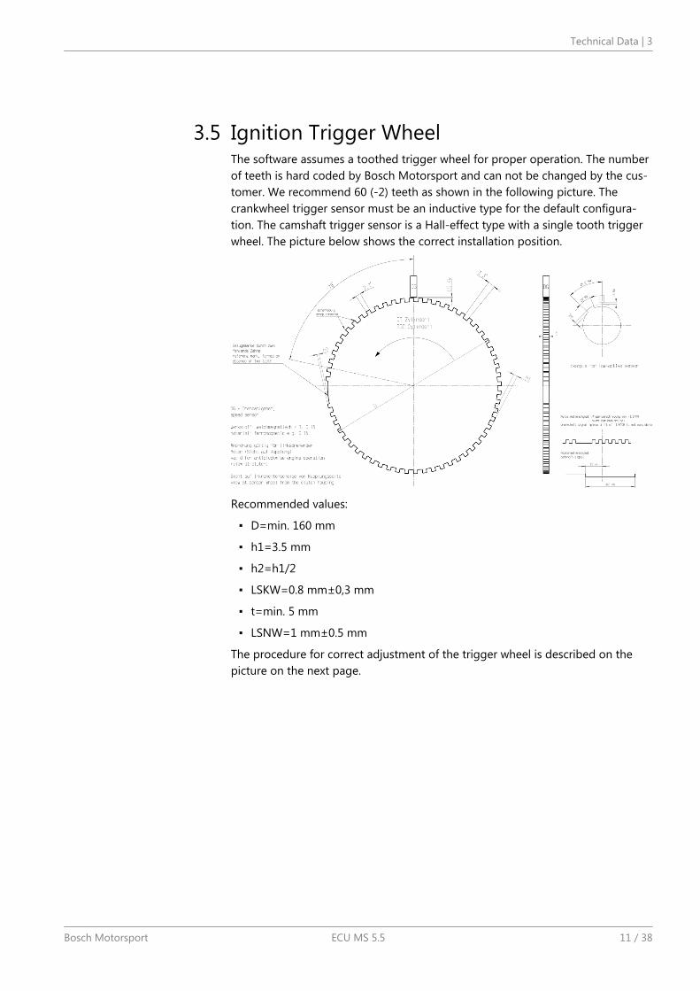
Ignition Trigger WheelThe software assumes a toothed trigger wheel for proper operation. The numberof teeth is hard coded by Bosch Motorsport and can not be changed by the cus-tomer. We recommend 60 (-2) teeth as shown in the following picture. Thecrankwheel trigger sensor must be an inductive type for the default configura-tion. The camshaft trigger sensor is a Hall-effect type with a single tooth triggerwheel. The picture below shows the correct installation position.
Recommended values:
D=min. 160 mm
h1=3.5 mm
h2=h1/2
LSKW=0.8 mm±0,3 mm
t=min. 5 mm
LSNW=1 mm±0.5 mm
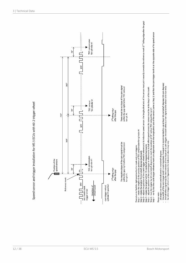
The procedure for correct adjustment of the trigger wheel is described on thepicture on the next page.
3.5
Technical Data | 3
Bosch Motorsport ECU MS 5.5 11 / 38
3 | Technical Data
12 / 38 ECU MS 5.5 Bosch Motorsport
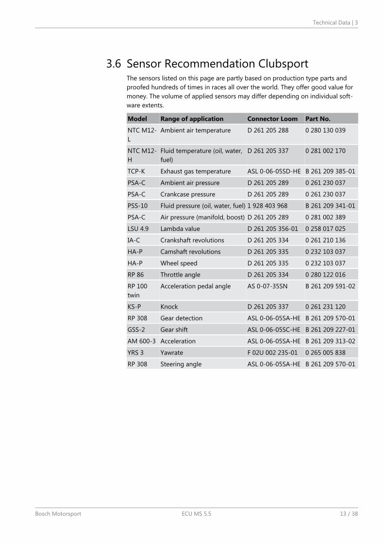
Sensor Recommendation ClubsportThe sensors listed on this page are partly based on production type parts andproofed hundreds of times in races all over the world. They offer good value formoney. The volume of applied sensors may differ depending on individual soft-ware extents.
Model Range of application Connector Loom Part No.
NTC M12-L
Ambient air temperature D 261 205 288 0 280 130 039
NTC M12-H
Fluid temperature (oil, water,fuel)
D 261 205 337 0 281 002 170
TCP-K Exhaust gas temperature ASL 0-06-05SD-HE B 261 209 385-01
PSA-C Ambient air pressure D 261 205 289 0 261 230 037
PSA-C Crankcase pressure D 261 205 289 0 261 230 037
PSS-10 Fluid pressure (oil, water, fuel) 1 928 403 968 B 261 209 341-01
PSA-C Air pressure (manifold, boost) D 261 205 289 0 281 002 389
LSU 4.9 Lambda value D 261 205 356-01 0 258 017 025
IA-C Crankshaft revolutions D 261 205 334 0 261 210 136
HA-P Camshaft revolutions D 261 205 335 0 232 103 037
HA-P Wheel speed D 261 205 335 0 232 103 037
RP 86 Throttle angle D 261 205 334 0 280 122 016
RP 100twin
Acceleration pedal angle AS 0-07-35SN B 261 209 591-02
KS-P Knock D 261 205 337 0 261 231 120
RP 308 Gear detection ASL 0-06-05SA-HE B 261 209 570-01
GSS-2 Gear shift ASL 0-06-05SC-HE B 261 209 227-01
AM 600-3 Acceleration ASL 0-06-05SA-HE B 261 209 313-02
YRS 3 Yawrate F 02U 002 235-01 0 265 005 838
RP 308 Steering angle ASL 0-06-05SA-HE B 261 209 570-01
3.6
Technical Data | 3
Bosch Motorsport ECU MS 5.5 13 / 38
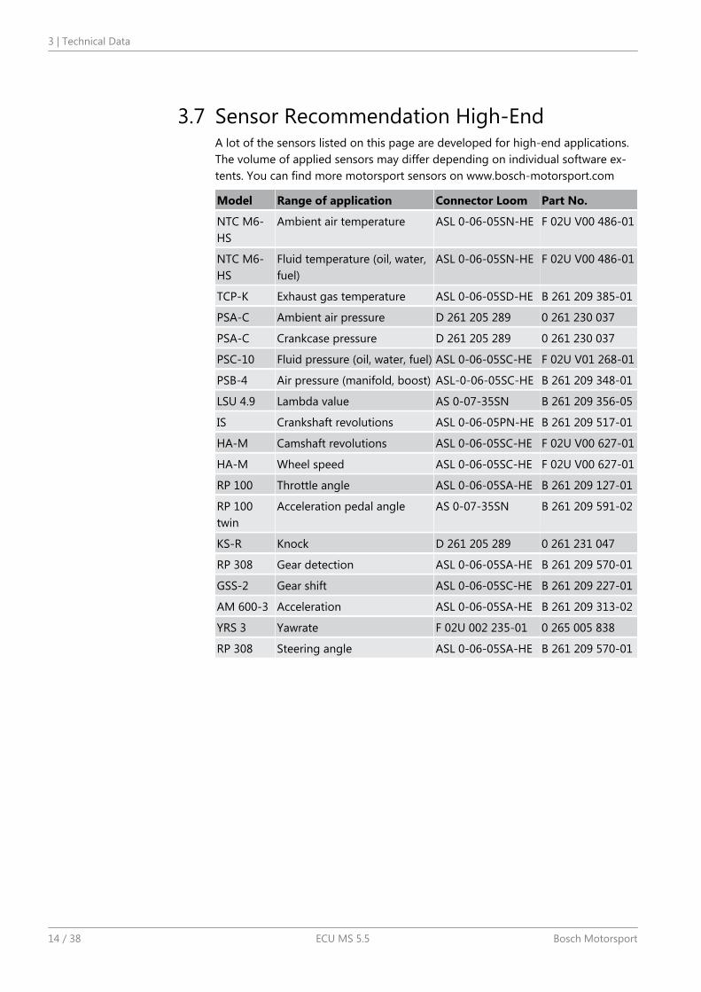
Sensor Recommendation High-EndA lot of the sensors listed on this page are developed for high-end applications.The volume of applied sensors may differ depending on individual software ex-tents. You can find more motorsport sensors on www.bosch-motorsport.com
Model Range of application Connector Loom Part No.
NTC M6-HS
Ambient air temperature ASL 0-06-05SN-HE F 02U V00 486-01
NTC M6-HS
Fluid temperature (oil, water,fuel)
ASL 0-06-05SN-HE F 02U V00 486-01
TCP-K Exhaust gas temperature ASL 0-06-05SD-HE B 261 209 385-01
PSA-C Ambient air pressure D 261 205 289 0 261 230 037
PSA-C Crankcase pressure D 261 205 289 0 261 230 037
PSC-10 Fluid pressure (oil, water, fuel) ASL 0-06-05SC-HE F 02U V01 268-01
PSB-4 Air pressure (manifold, boost) ASL-0-06-05SC-HE B 261 209 348-01
LSU 4.9 Lambda value AS 0-07-35SN B 261 209 356-05
IS Crankshaft revolutions ASL 0-06-05PN-HE B 261 209 517-01
HA-M Camshaft revolutions ASL 0-06-05SC-HE F 02U V00 627-01
HA-M Wheel speed ASL 0-06-05SC-HE F 02U V00 627-01
RP 100 Throttle angle ASL 0-06-05SA-HE B 261 209 127-01
RP 100twin
Acceleration pedal angle AS 0-07-35SN B 261 209 591-02
KS-R Knock D 261 205 289 0 261 231 047
RP 308 Gear detection ASL 0-06-05SA-HE B 261 209 570-01
GSS-2 Gear shift ASL 0-06-05SC-HE B 261 209 227-01
AM 600-3 Acceleration ASL 0-06-05SA-HE B 261 209 313-02
YRS 3 Yawrate F 02U 002 235-01 0 265 005 838
RP 308 Steering angle ASL 0-06-05SA-HE B 261 209 570-01
3.7
3 | Technical Data
14 / 38 ECU MS 5.5 Bosch Motorsport
Starting up the ECU
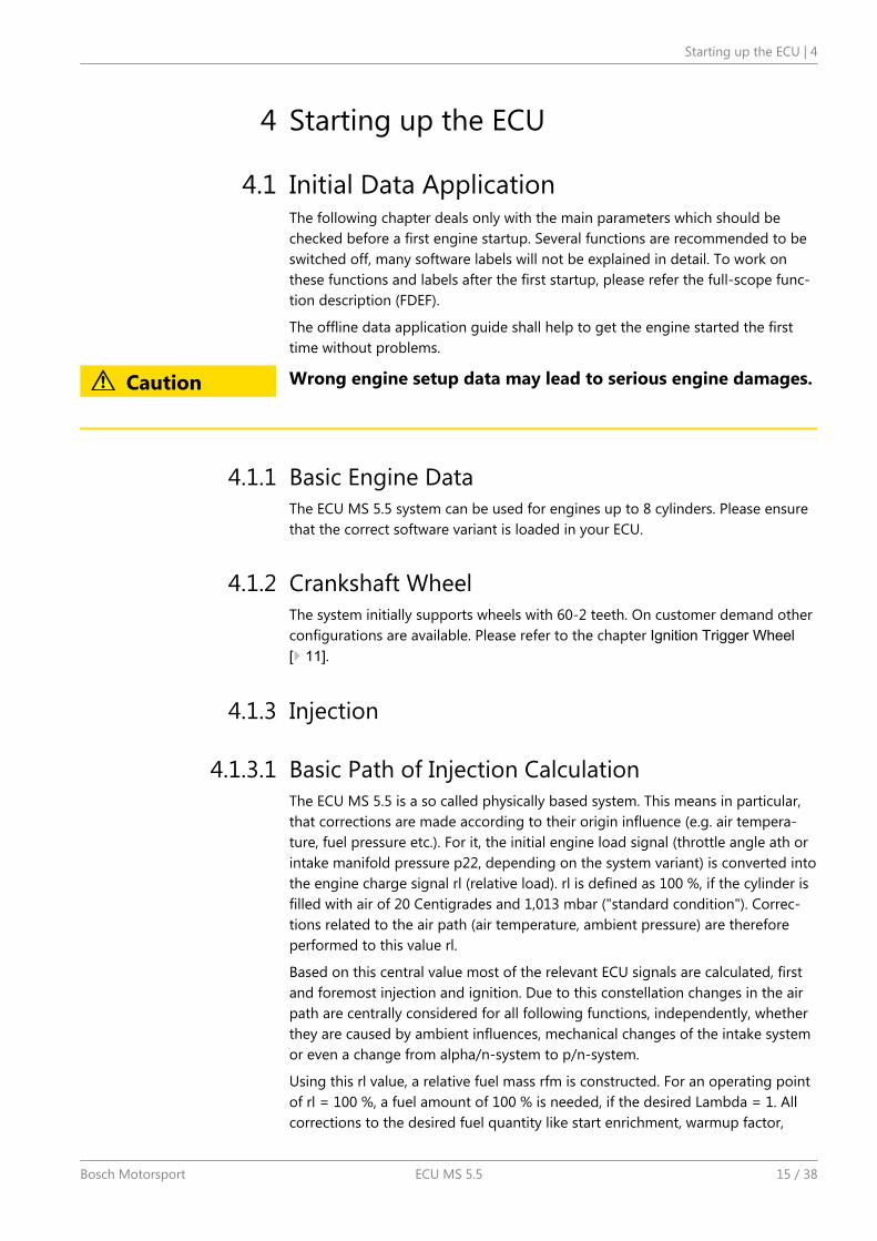
Initial Data ApplicationThe following chapter deals only with the main parameters which should bechecked before a first engine startup. Several functions are recommended to beswitched off, many software labels will not be explained in detail. To work onthese functions and labels after the first startup, please refer the full-scope func-tion description (FDEF).
The offline data application guide shall help to get the engine started the firsttime without problems.
Caution Wrong engine setup data may lead to serious engine damages.
Basic Engine DataThe ECU MS 5.5 system can be used for engines up to 8 cylinders. Please ensurethat the correct software variant is loaded in your ECU.
Crankshaft WheelThe system initially supports wheels with 60-2 teeth. On customer demand otherconfigurations are available. Please refer to the chapter Ignition Trigger Wheel[ 11].
Injection
Basic Path of Injection CalculationThe ECU MS 5.5 is a so called physically based system. This means in particular,that corrections are made according to their origin influence (e.g. air tempera-ture, fuel pressure etc.). For it, the initial engine load signal (throttle angle ath orintake manifold pressure p22, depending on the system variant) is converted intothe engine charge signal rl (relative load). rl is defined as 100 %, if the cylinder isfilled with air of 20 Centigrades and 1,013 mbar ("standard condition"). Correc-tions related to the air path (air temperature, ambient pressure) are thereforeperformed to this value rl.
Based on this central value most of the relevant ECU signals are calculated, firstand foremost injection and ignition. Due to this constellation changes in the airpath are centrally considered for all following functions, independently, whetherthey are caused by ambient influences, mechanical changes of the intake systemor even a change from alpha/n-system to p/n-system.
Using this rl value, a relative fuel mass rfm is constructed. For an operating pointof rl = 100 %, a fuel amount of 100 % is needed, if the desired Lambda = 1. Allcorrections to the desired fuel quantity like start enrichment, warmup factor,
4
4.1
4.1.1
4.1.2
4.1.3
4.1.3.1
Starting up the ECU | 4
Bosch Motorsport ECU MS 5.5 15 / 38
transient compensation, but also the desired Lambda value and the correctionfactor of the Lambda control are considered as an adjustment of this relative fuelmass. I.e. all corrections are still made independently of the size and other speci-fications of the injectors.
Next step is the conversion of the relative fuel mass to a desired injection time te.Here the engine´s displacement, the fuel flow through the injector and influencesof the fuel pressure are considered.
Finally the actual duration of the control pulse ti is calculated, considering pick-up delays of the injectors, fuel cutoff (e.g. overrun cutoff, speed limiter, gear cut)and cylinder individual correction factors.
Please refer also to the system overview in the Function Description ECOV.
Initial StepsThe following data must be initially set to start injection calibration for the firsttime:
DISPLACEMENTDisplacement of the engine
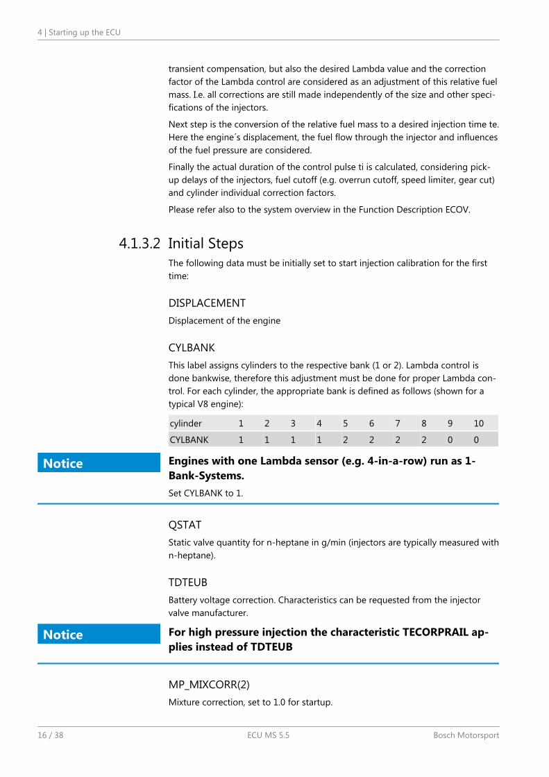
CYLBANKThis label assigns cylinders to the respective bank (1 or 2). Lambda control isdone bankwise, therefore this adjustment must be done for proper Lambda con-trol. For each cylinder, the appropriate bank is defined as follows (shown for atypical V8 engine):
cylinder 1 2 3 4 5 6 7 8 9 10
CYLBANK 1 1 1 1 2 2 2 2 0 0
Notice Engines with one Lambda sensor (e.g. 4-in-a-row) run as 1-Bank-Systems.Set CYLBANK to 1.
QSTATStatic valve quantity for n-heptane in g/min (injectors are typically measured withn-heptane).
TDTEUBBattery voltage correction. Characteristics can be requested from the injectorvalve manufacturer.
Notice For high pressure injection the characteristic TECORPRAIL ap-plies instead of TDTEUB
MP_MIXCORR(2)Mixture correction, set to 1.0 for startup.
4.1.3.2
4 | Starting up the ECU
16 / 38 ECU MS 5.5 Bosch Motorsport
MIXCORR_APPGlobal factor for mixture correction, set to 1.0 for startup.
FINJ_CYL1 … 8Cylinder individual corrections. Set to 1.0 for startup. Numbering refers to me-chanical cylinders as used at CYLBANK.
CWPRAILCORIf a correction by fuel pressure is intended, set = 1. In this case please set PRAIL-REF according to the referenced fuel pressure. Also refer to MP_P22MOD. Usuallythe predefined values are suiteable. If unsure, set CWPRAILCOR to 0 for firststartup.
FRLPAMBCorrection via ambient pressure. Usually the predefined values are suiteable. Ifunsure, set FRLPAMB to 1.0 for first startup. For p/n-systems PALTCOR applies asan offset correction. Neutralize by setting to 0.0.
FRLTINTCorrection via ambient temperature. Usually the predefined values are suiteable.If unsure, set FRLTINT to 1.0 for first startup. For p/n-systems FRLPTINT appliesaccordingly.
FINJ_WARMUPCorrection via engine coolant temperature. Usually the predefined values aresuiteable. Ensure, that for coolant temperatures driven on your dyno during cali-bration, no warmup factor applies (i.e. FINJ_WARMUP is 0.0 for this temperature).
MP_LAM_MP1Desired Lambda value, valid for map position 1. According to your expectations,e.g. 0.9. For alternative positions of your map switch the maps MP_LAM_MP2 (3)or (_PACE) apply, therefore ensure correct switch position.
Injection Angle
MP_EOINJEnd of injection pulse, refers to combustion TDC (degrees before TDC). Makesure, the injection is finished before the inlet valve closes.
Try 200° to 300° for first startup. Direct injection may differ.
Before calibration starts, turn off Lambda closed loop control:
CWLCCodeword for enabling of the Lambda closed loop control. Set to 0 during initialcalibration, afterwards = 1.
4.1.3.3
Starting up the ECU | 4
Bosch Motorsport ECU MS 5.5 17 / 38
Finally the throttle angle potentiometer has to be calibrated (see chapter ThrottleAngle [ 21]), maximum engine speed should be defined for engine protection(see chapter Revlimit [ 19]), all sensors should be checked (see chapter Pe‐ripherals [ 21]) and the ignition parameters should be preset and observed(see chapter Ignition [ 18]).
Basic setup may now be started by setting the appropriate values in the mapMP_RL:
Load Map
MP_RLRelative load depending on throttle angle and engine speed. Set value until yourdesired Lambda is matched.
Notice If you operate a p/n-system, the maps MP_RLP1 … 4 are usedaccordingly. For details please refer to the Function DescriptionLOADCALC.
Injection StartAfter initial calibration the start factors for injection may be optimized.
FINJSTART_TMOTBasic start enrichment factor depending on the engine temperature.
MP_INJSTARTDecay of the start enrichment factor over the number of engine revolutions
Notice For details please refer to the Function Description IN-JPRECTRL.
Ignition
Notice Positive values stand for ignition angles before TDC, negativevalues after TDC. Begin with moderate values to protect yourengine from damages.
MP_IGN_STARTBase spark advance during engine start. Set to 5 to 10 deg, according to engine´srequirements.
MP_TDWELLCoil dwell time. Consult the coil manufacturer for details. Most coils need dwelltimes about 1.5 to 2.5 milliseconds at 12 to 14 V.
4.1.3.4
4.1.3.5
4.1.4
4 | Starting up the ECU
18 / 38 ECU MS 5.5 Bosch Motorsport
For further background information please refer to the Function Description IG-NITION.
DIGN_CYL1 … 8Cylinder individual corrections. Set to 0.0. Numbering refers to mechanical cylin-ders.
Ignition Map
MP_IGNBase ignition timing in deg crankshaft before TDC. Use modest values at the firsttime. Atmospheric engines may run safe at 20 to 25 deg in part load, turbo en-gines at high boosts may demand even less spark advance. These values arestrongly dependend on compression ratio, fuel quality, temperature and enginespecifics. If you know you’re using “poor” fuel, run at high temperatures or yourengine is very sensitive on spark advance, go to the safe side.
DIGN_MAP2 (3) / DIGN_PACEDelta value for spark advance depending on the map switch position. Ensure cor-rect switch position. If unsure, set to 0.0 for first startup.
IGN_IDLE_STATIgnition timing during idle. 10 deg are suitable for most applications.
NIDLE_NOM / DIGN_IDLECTRLDesired engine idle speed for idle stabilization. Set value to desired speed or de-activate stabilization by setting DIGN_IDLECTRL to 0.0.
RevlimitThe rev limiter works in two steps:
Soft limitation by ignition retardation or cylinder individual cutoff of injectionand/or igni-tion
Hard limitation by injection cut off and/or ignition cutoff of all cylinders
To achieve a good dynamic behaviour by advanced intervention, the enginespeed is predicted by means of the speed gradient.
NMAX_GEARMaximum engine speed for soft limiter. Set value according to engine´s require-ments.
DNMAXHOffset between soft limiter and hard limiter. 500 rpm should be suitable for mostof the projects.
4.1.4.1
4.1.5
Starting up the ECU | 4
Bosch Motorsport ECU MS 5.5 19 / 38
DNMAX_MAP2 (3)Delta value for rev limiter, depending on the map switch position. Ensure correctswitch position. If unsure, set to 0 for first startup.
TC_NMAXPRPrediction time for rev limiter, depends on the inertia torque of the engine. If os-cillations occur, reduce value or turn off by setting = 0.0.
CWNMAX_CUTOFFCodeword for type of intervention during soft limiter.
0 = only ignition retard,
1 = injection cutoff,
2 = ignition cutoff,
3 = injection and ignition cutoff.
CWNMAXH_CUTOFFCodeword for type of intervention during hard limiter. Set:
1 = for injection cutoff,
2 = ignition cutoff,
3 = injection and ignition cutoff.
NMAX_PDetermines the slope of the soft limiter between soft limit and hard limit. Prede-fined. Vary according to your engine´s dynamic behavior.
Cutoff Pattern
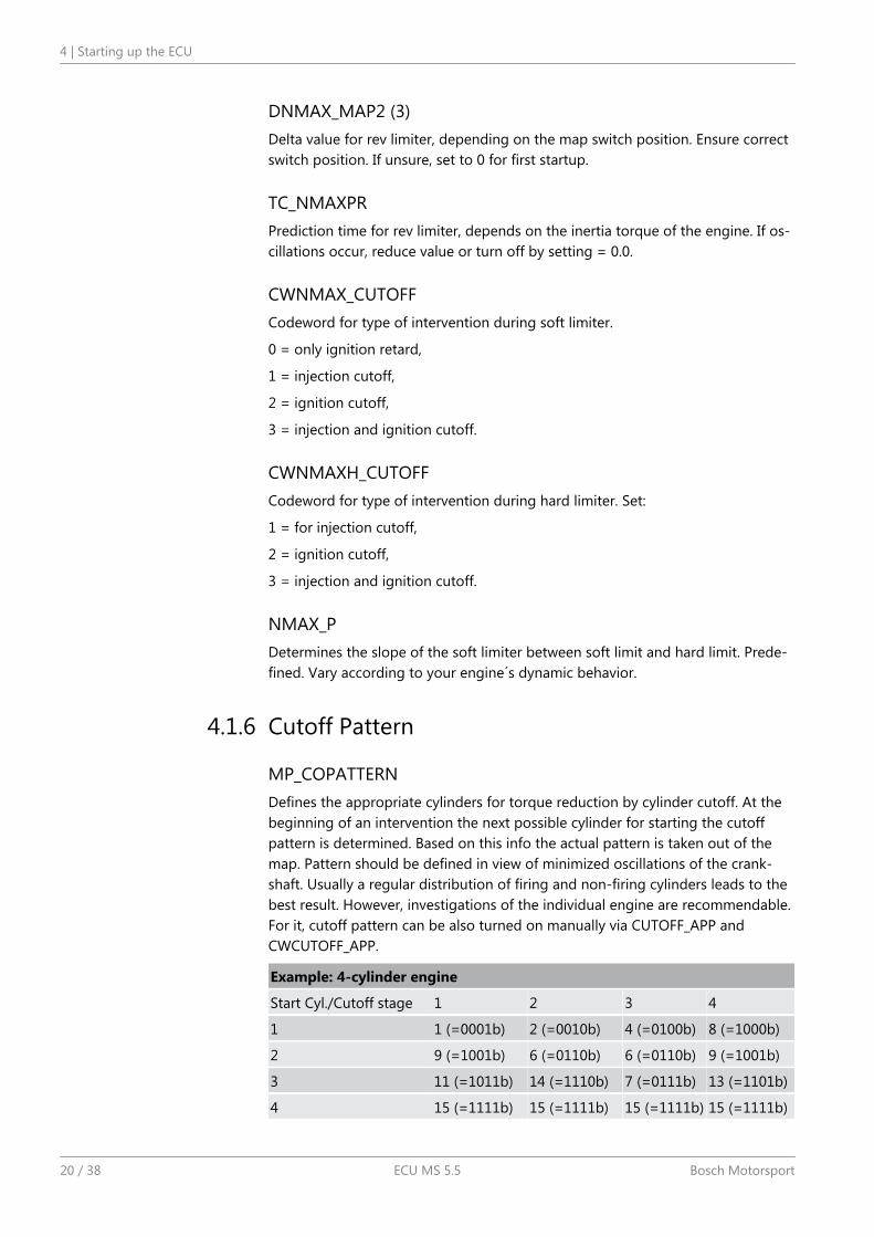
MP_COPATTERNDefines the appropriate cylinders for torque reduction by cylinder cutoff. At thebeginning of an intervention the next possible cylinder for starting the cutoffpattern is determined. Based on this info the actual pattern is taken out of themap. Pattern should be defined in view of minimized oscillations of the crank-shaft. Usually a regular distribution of firing and non-firing cylinders leads to thebest result. However, investigations of the individual engine are recommendable.For it, cutoff pattern can be also turned on manually via CUTOFF_APP andCWCUTOFF_APP.
Example: 4-cylinder engine
Start Cyl./Cutoff stage 1 2 3 4
1 1 (=0001b) 2 (=0010b) 4 (=0100b) 8 (=1000b)
2 9 (=1001b) 6 (=0110b) 6 (=0110b) 9 (=1001b)
3 11 (=1011b) 14 (=1110b) 7 (=0111b) 13 (=1101b)
4 15 (=1111b) 15 (=1111b) 15 (=1111b) 15 (=1111b)
4.1.6
4 | Starting up the ECU
20 / 38 ECU MS 5.5 Bosch Motorsport
The cylinders are assigned bitwise, the lowest bit represents cylinder 1. Number-ing refers to mechanical cylinders.
e.g. pattern = 9: Mechanical cylinders 1 and 4 are fade out.
CUTOFF_APPCutoff pattern for test purposes. Bit representation as described at MP_COPAT-TERN.
CWCUTOFF_APPCodeword for type of intervention during test cutoff. Set:
1 = injection cutoff,
2 = ignition cutoff,
3 = injection and ignition cutoff.
Notice This option is also useful for searching a misfiring cylinder.Select one cylinder after the other during test cutoff and watch your engine.
Peripherals1. Before switching the system on, check the following steps …
… Make sure the battery is connected properly,
… all sensors are connected,
… ground wiring is fixed before powering up the system.
2. Check all sensors for errors (bits …_e) before starting the engine.
Sensors and peripherals can be checked when the system is powered up electri-cally.
Notice Do not start the engine before all steps in this chapter are car-ried out.
Throttle
Throttle Angle
UDTHR_MIN, UDTHR_MAXMinimum and maximum accepted sensor voltage. When violated, an error is set(E_thr = 1). Set to approx. 100 mV/4900 mV.
Check if the sensor output value uthrottle is changing when throttle ismoved.
4.2
4.2.1
4.2.1.1
Starting up the ECU | 4
Bosch Motorsport ECU MS 5.5 21 / 38
Calibration
THRADJPOS1Lower calibration point, set to 0.0 %.
THRADJPOS2Full load point, set to 100.0 %.
CWTHRADJProcedure:
1. Close throttle and set CWTHRADJ to 1.
2. Open throttle fully and set CWTHRADJ to 2.
3. Adjust the throttle to idle point.
Do not forget to set CWTHRADJ back to 0. Check calibration by movingthrottle.
Notice It is also possible to recalibrate the idle point afterwards.For it, proceed as follows.
THRADJIDLE: set value according to your idle position, e.g. 2.0 %.
CWTHRADJ: set to 3.
For further details and project specific variants please refer to the Function De-scription ISTHROTTLE.
PressuresAll pressures are calculated in the same way. The system usually offers oil pres-sure (poil), ambient pressure (pamb), crank pressure (pcrank), water pressure(pwat) and fuel pressure (pfuel). The extent may vary according to software var-iants.
Example: Ambient pressure
PAMB_OFF, PAMB_GRDSensor offset and gradient. Consult the sensor manufacturer for details.
UPAMB_MIN, UPAMB_MAXMinimum and maximum accepted sensor voltage. When violated, an error is set(E_pamb = 1). Set to approx. 100 mV / 4900 mV.
PAMB_DEFDefault value. If a sensor error is set, the output is switched to the default.
4.2.1.2
4.2.2
4 | Starting up the ECU
22 / 38 ECU MS 5.5 Bosch Motorsport
FCPAMBFilter constant. For ambient pressure use 1 second, for other pressures chooseappropriate values, ~ 100 to 200 milliseconds.
All other variables are named by the same rule, replace “pamb” by e.g. “poil” toapply data for the oil pressure sensor.
For further details and project specific variants please refer to the Function De-scription ISPRESS.
TemperaturesAll temperatures except the exhaust gas temperature are calculated in the sameway. The system usually offers oil temperature (toil), intake air temperature (tint),engine temperature (tmot), fuel temperature (tfuel), …
Example: Intake air temperature
UTINT_MIN, UTINT_MAXMinimum and maximum accepted sensor voltage. When violated, an error is set(E_tint = 1). Set to approx. 100 mV / 4900 mV.
TINT_CONVSensor characteristic. Consult the sensor manufacturer.
PULLUP_TINTValue of the used pull-up resistor. If only the ECU´s pull-up is used (standardcase) take the predefined value of 3000 Ω.
The exhaust gas temperature is measured via NiCrNi elements using a specialevaluation circuit. Predefined values should be suitable.
For further details and project specific variants please refer to the Function De-scription ISTEMP.
Vehicle TestBefore starting with your vehicle test, some initial data should be set:
INC_FRONTNumber of pulses per revolution of the front speed signal
INC_REARNumber of pulses per revolution of the rear speed signal
CIRCWHEEL_FFor wheel circumference of the front wheels; Consider dynamic increase of yourtyre.
4.2.3
4.3
Starting up the ECU | 4
Bosch Motorsport ECU MS 5.5 23 / 38
CIRCWHEEL_RFor wheel circumference of the rear wheels; Consider dynamic increase of yourtyre.
If a lap trigger is used, the lap length must be entered for plausibility:
LLAPSet value to the length of your track.
For detailed information please refer to the Function Descriptions CARSPEED andLAPFUNC.
4 | Starting up the ECU
24 / 38 ECU MS 5.5 Bosch Motorsport
Data loggingThe MS 5.5 has an internal logger, presenting a cost efficient and weight opti-mized all-in-one solution.
Software
Which software tools are available?
RaceCon Create and configure a Project.
Configuration & Management of Recordings
Create a new recording.
Add channels to a recording.
Create User-defined Conditions for the recording.
Download recording configuration.
WinDARAB Upload recorded data.
Display and analyze the data.
Starting up the data loggingThe following chapters demonstrate how to set up data logging and how to ana-lyze the recorded data. It shows the most important functions and features ofRaceCon and WinDarab. For this tutorial we assume, that you have a MS 5.5 con-nected to your computer via an MSA II Box or an Ethernet line.
Caution Don´t start up the engine unless the steps described in chapterStarting up the ECU [ 15] have been performed.
Ethernet configurationThe Ethernet communication is designed to work without manual configuration.There may be special situations where manual configuration of the computernetwork adapter is required. Please refer to the appendix. Communication is de-signed to work without manual configuration. There may be special situationswhere manual configuration of the computer network adapter is required. Pleaserefer to the appendix.
Welcome to RaceConAfter the start of the program, RaceCon opens a view Welcome to RaceCon.With Last Projects, former projects can be opened directly.
5
5.1
5.2
5.2.1
5.3
Data logging | 5
Bosch Motorsport ECU MS 5.5 25 / 38
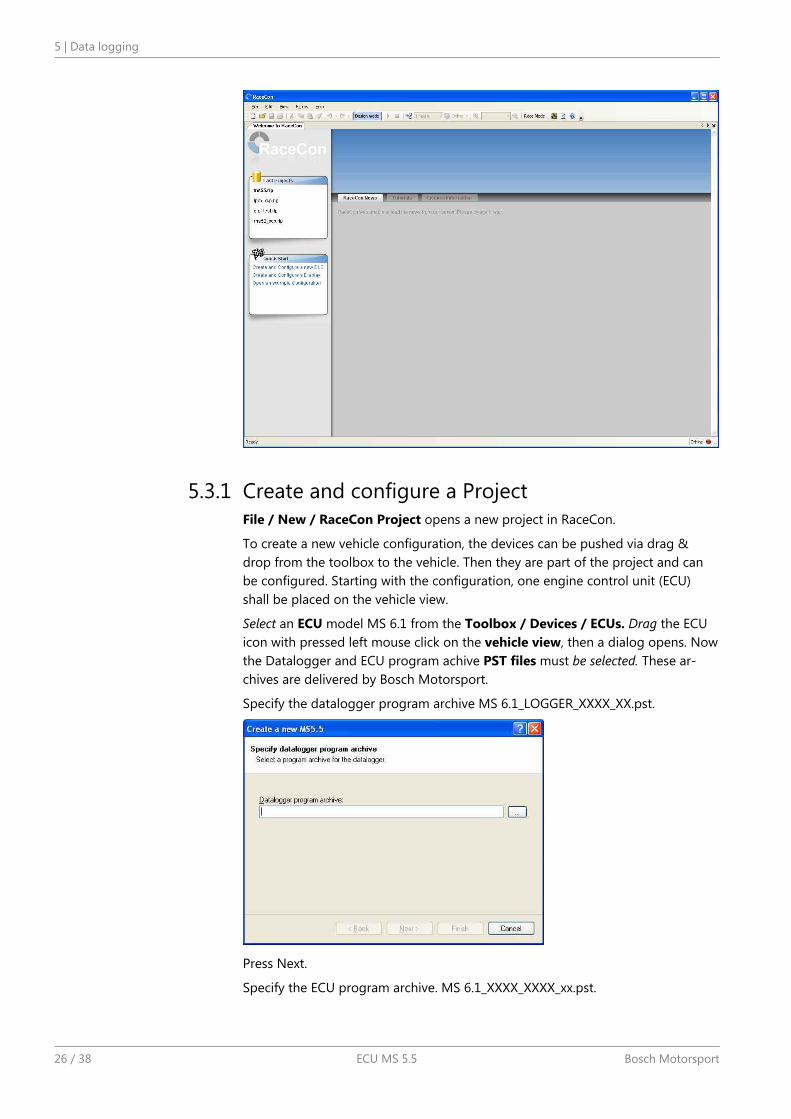
Create and configure a ProjectFile / New / RaceCon Project opens a new project in RaceCon.
To create a new vehicle configuration, the devices can be pushed via drag &drop from the toolbox to the vehicle. Then they are part of the project and canbe configured. Starting with the configuration, one engine control unit (ECU)shall be placed on the vehicle view.
Select an ECU model MS 6.1 from the Toolbox / Devices / ECUs. Drag the ECUicon with pressed left mouse click on the vehicle view, then a dialog opens. Nowthe Datalogger and ECU program achive PST files must be selected. These ar-chives are delivered by Bosch Motorsport.
Specify the datalogger program archive MS 6.1_LOGGER_XXXX_XX.pst.
Press Next.
Specify the ECU program archive. MS 6.1_XXXX_XXXX_xx.pst.
5.3.1
5 | Data logging
26 / 38 ECU MS 5.5 Bosch Motorsport
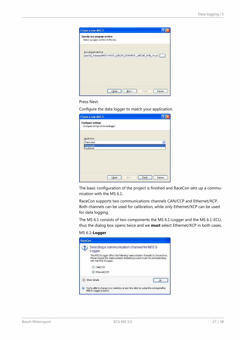
Press Next.
Configure the data logger to match your application.
The basic configuration of the project is finished and RaceCon sets up a commu-nication with the MS 6.1.
RaceCon supports two communications channels CAN/CCP and Ethernet/XCP.Both channels can be used for calibration, while only Ethernet/XCP can be usedfor data logging.
The MS 6.1 consists of two components the MS 6.1-Logger and the MS 6.1-ECU,thus the dialog box opens twice and we must select Ethernet/XCP in both cases.
MS 6.1-Logger
Data logging | 5
Bosch Motorsport ECU MS 5.5 27 / 38
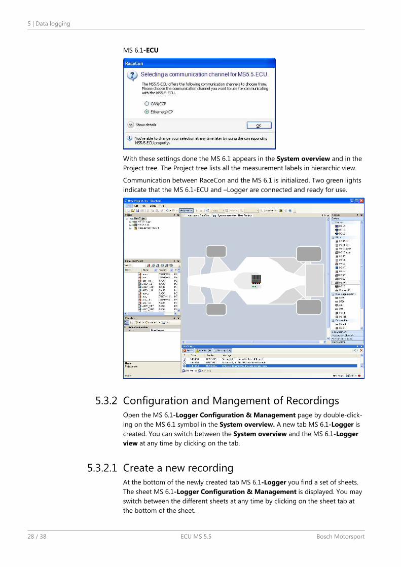
MS 6.1-ECU
With these settings done the MS 6.1 appears in the System overview and in theProject tree. The Project tree lists all the measurement labels in hierarchic view.
Communication between RaceCon and the MS 6.1 is initialized. Two green lightsindicate that the MS 6.1-ECU and –Logger are connected and ready for use.
Configuration and Mangement of RecordingsOpen the MS 6.1-Logger Configuration & Management page by double-click-ing on the MS 6.1 symbol in the System overview. A new tab MS 6.1-Logger iscreated. You can switch between the System overview and the MS 6.1-Loggerview at any time by clicking on the tab.
Create a new recordingAt the bottom of the newly created tab MS 6.1-Logger you find a set of sheets.The sheet MS 6.1-Logger Configuration & Management is displayed. You mayswitch between the different sheets at any time by clicking on the sheet tab atthe bottom of the sheet.
5.3.2
5.3.2.1
5 | Data logging
28 / 38 ECU MS 5.5 Bosch Motorsport
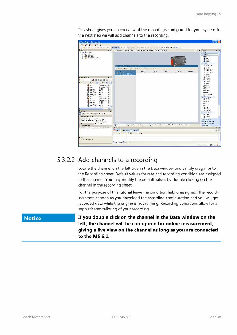
This sheet gives you an overview of the recordings configured for your system. Inthe next step we will add channels to the recording.
Add channels to a recordingLocate the channel on the left side in the Data window and simply drag it ontothe Recording sheet. Default values for rate and recording condition are assignedto the channel. You may modify the default values by double clicking on thechannel in the recording sheet.
For the purpose of this tutorial leave the condition field unassigned. The record-ing starts as soon as you download the recording configuration and you will getrecorded data while the engine is not running. Recording conditions allow for asophisticated tailoring of your recording.
Notice If you double click on the channel in the Data window on theleft, the channel will be configured for online measurement,giving a live view on the channel as long as you are connectedto the MS 6.1.
5.3.2.2
Data logging | 5
Bosch Motorsport ECU MS 5.5 29 / 38
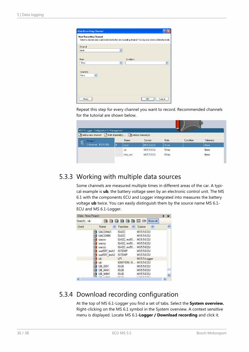
Repeat this step for every channel you want to record. Recommended channelsfor the tutorial are shown below.
Working with multiple data sourcesSome channels are measured multiple times in different areas of the car. A typi-cal example is ub, the battery voltage seen by an electronic control unit. The MS6.1 with the components ECU and Logger integrated into measures the batteryvoltage ub twice. You can easily distinguish them by the source name MS 6.1-ECU and MS 6.1-Logger.
Download recording configurationAt the top of MS 6.1-Logger you find a set of tabs. Select the System overview.Right-clicking on the MS 6.1 symbol in the System overview. A context sensitivemenu is displayed. Locate MS 6.1-Logger / Download recording and click it.
5.3.3
5.3.4
5 | Data logging
30 / 38 ECU MS 5.5 Bosch Motorsport
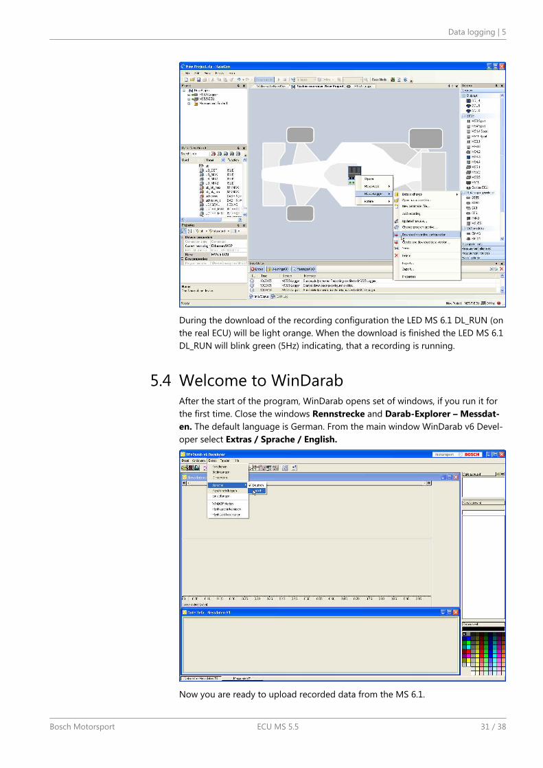
During the download of the recording configuration the LED MS 6.1 DL_RUN (onthe real ECU) will be light orange. When the download is finished the LED MS 6.1DL_RUN will blink green (5Hz) indicating, that a recording is running.
Welcome to WinDarabAfter the start of the program, WinDarab opens set of windows, if you run it forthe first time. Close the windows Rennstrecke and Darab-Explorer – Messdat-en. The default language is German. From the main window WinDarab v6 Devel-oper select Extras / Sprache / English.
Now you are ready to upload recorded data from the MS 6.1.
5.4
Data logging | 5
Bosch Motorsport ECU MS 5.5 31 / 38
Upload recorded data
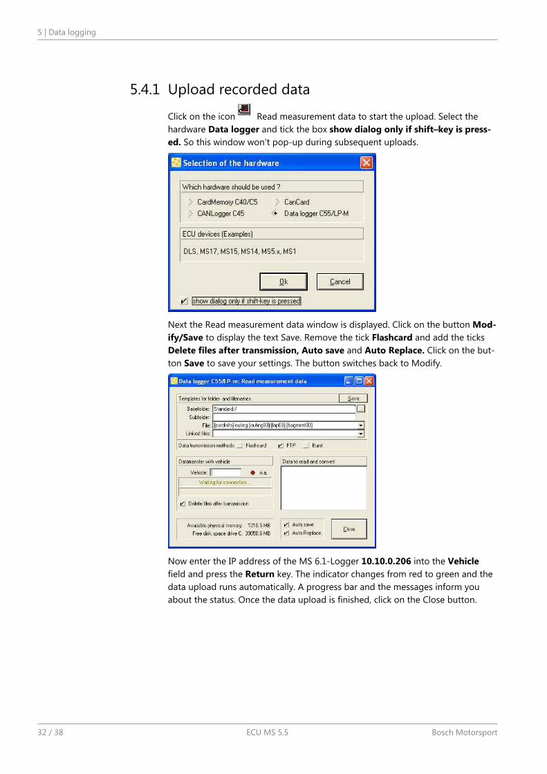
Click on the icon Read measurement data to start the upload. Select thehardware Data logger and tick the box show dialog only if shift–key is press-ed. So this window won't pop-up during subsequent uploads.
Next the Read measurement data window is displayed. Click on the button Mod-ify/Save to display the text Save. Remove the tick Flashcard and add the ticksDelete files after transmission, Auto save and Auto Replace. Click on the but-ton Save to save your settings. The button switches back to Modify.
Now enter the IP address of the MS 6.1-Logger 10.10.0.206 into the Vehiclefield and press the Return key. The indicator changes from red to green and thedata upload runs automatically. A progress bar and the messages inform youabout the status. Once the data upload is finished, click on the Close button.
5.4.1
5 | Data logging
32 / 38 ECU MS 5.5 Bosch Motorsport
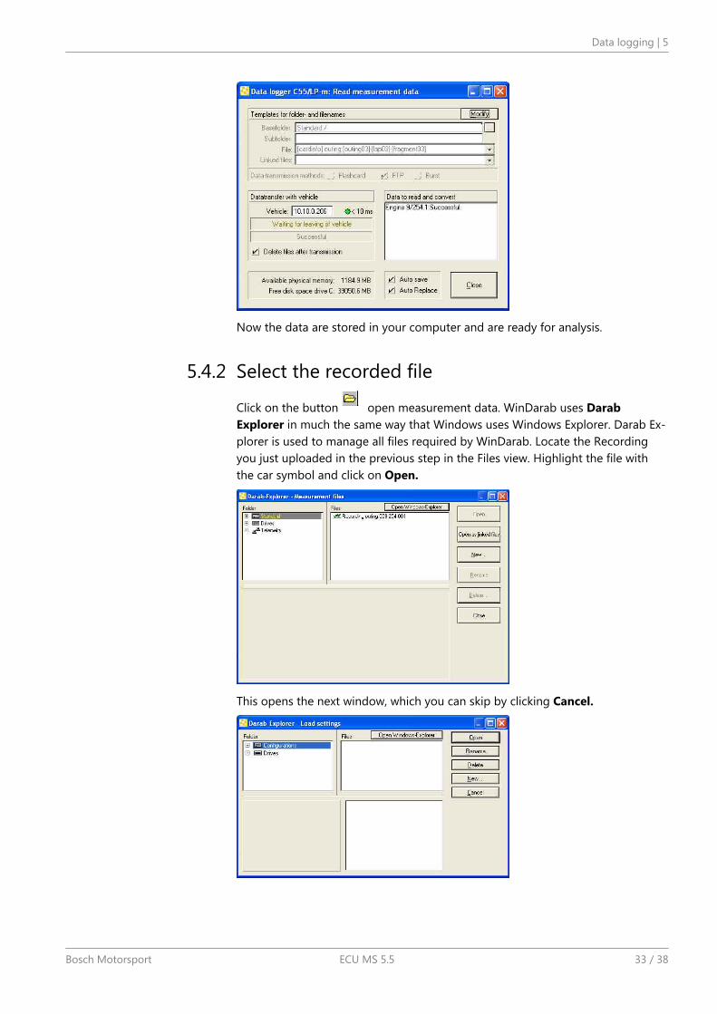
Now the data are stored in your computer and are ready for analysis.
Select the recorded file
Click on the button open measurement data. WinDarab uses DarabExplorer in much the same way that Windows uses Windows Explorer. Darab Ex-plorer is used to manage all files required by WinDarab. Locate the Recordingyou just uploaded in the previous step in the Files view. Highlight the file withthe car symbol and click on Open.
This opens the next window, which you can skip by clicking Cancel.
5.4.2
Data logging | 5
Bosch Motorsport ECU MS 5.5 33 / 38
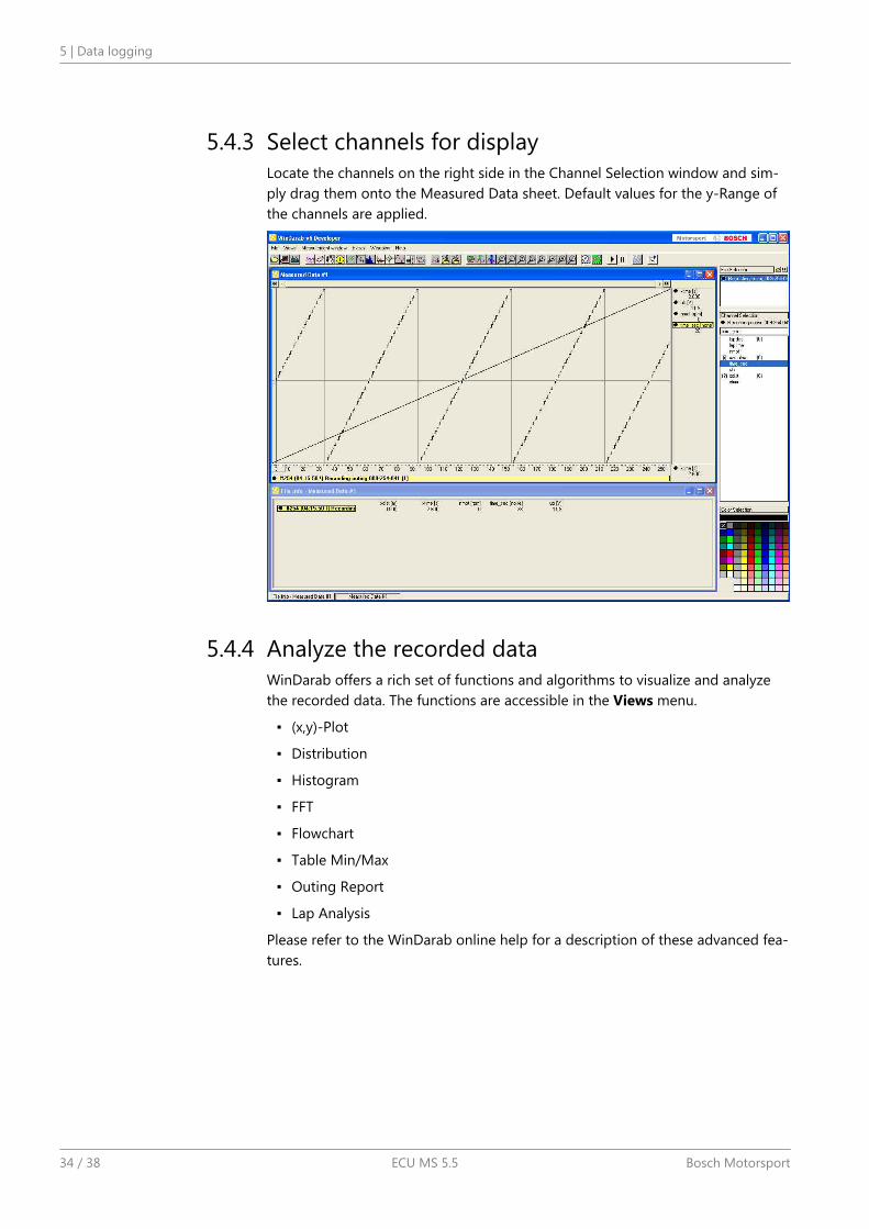
Select channels for displayLocate the channels on the right side in the Channel Selection window and sim-ply drag them onto the Measured Data sheet. Default values for the y-Range ofthe channels are applied.
Analyze the recorded dataWinDarab offers a rich set of functions and algorithms to visualize and analyzethe recorded data. The functions are accessible in the Views menu.
(x,y)-Plot
Distribution
Histogram
FFT
Flowchart
Table Min/Max
Outing Report
Lap Analysis
Please refer to the WinDarab online help for a description of these advanced fea-tures.
5.4.3
5.4.4
5 | Data logging
34 / 38 ECU MS 5.5 Bosch Motorsport

ExtensibilityWe developed a lot of extras for the ECUs. That is e.g. Displays and Telemetryunits. The communication via Ethernet instead of CAN makes the system workvery much quicker.
Find more information on our website on www.bosch-motorsport.com
6
Extensibility | 6
Bosch Motorsport ECU MS 5.5 35 / 38
AppendicesThe Ethernet communication is designed to work without manual configuration.There may be special situations where manual configuration of the computersnetwork adapter is required.
Reasons for manual configuration:
The computer network interface was configured to use a fixed IP-Address. Thenetwork interface should be configured for automatic IP-Address. The MS 5.5runs a DHCP server which automatically provides the required configuration tothe computer network interface.
If it is not practical to use an automatic IP-Address the computer network inter-face must be set to:
IP-Address: 10.10.0.14
Netmask: 255.255.255.0
Standard-Gateway: <empty>
A firewall is installed on the computer. A firewall is a software that protects acomputer from unauthorized access, especially when connected to the internet.This firewall may block parts or all the communication between your computerand the MS 5.5.
Please consult your computer administrator to disable the firewall for this inter-face.
7
7 | Appendices
36 / 38 ECU MS 5.5 Bosch Motorsport

Bosch Engineering GmbHMotorsportRobert-Bosch-Allee 174232 AbstattGermanywww.bosch-motorsport.com