ed power take-off activation
TRANSCRIPT
22:10-043 Issue 3 en-G
ED power take-off activation
FunctionMore information on how power take-offs can be combined is found in the document Power take-off combinations under Power take-offs and hydraulics.
FunctionThe function is intended to activate the power take-off from the driver area and from outside the cab. The power take-off is controlled by the BCI control unit. An ED power take-off cannot be engaged and disengaged like other power take-offs.
If a hydraulic pump is connected to the power take-off, this control can, for example, be used to control a bypass valve to pressurise the hydraulic system if required.
Changes to adjustable parameters are done using SDP3 (Scania Diagnos & Programmer 3).
For Euro 6, the silencer is automatically regenerated. When this occurs, the vehicle’s control units regulate the speed and power, which affects the power take-off. In those cases where the drive from the power take-off must have a stable speed, the connec-tion must be done via preparation from Scania or via connection to the BCI control unit.
B 1 (18)© Scania CV AB 2017, Sweden
ED power take-off activationFunction
ActivationThere are different conditions to activate the power take-off. Depending on the pow-er take-off type there may be permanent activation conditions and selectable activa-tion conditions. The selectable activation conditions’ parameters can be set as required for the particular installation. The activation conditions are there to protect the bodywork equipment.
If all activation conditions are fulfilled, the function can be activated via BIC (Bod-ywork Interface Configuration) and External CAN.
The switch must be of the 2-position switch type.
Permanent activation conditions• No permanent activation conditions.
Selectable activation conditions• Applied parking brake conditions
If the vehicle is equipped with BCI functionality, then the following activation con-ditions can also be used.
• Neutral position conditions
• Reverse gear conditions
• Upper engine speed limit for activation
• Lower engine speed limit for activation
• Upper vehicle speed limit for activation
• Lower vehicle speed limit for activation
© Scania CV AB 2017, Sweden22:10-043 Issue 3 en-GB 2 (18)
ED power take-off activationFunction
Activation settingsThere are 3 different activation settings.1
• Manual
• Automatic
• Drive position
ManualFor activation using the Manual setting, all the activation conditions must be fulfilled before the power take-off can be activated with the switch. If the switch is activated when the activation conditions are fulfilled, the power take-off is not activated. De-activate and activate the switch again to activate the power take-off.
AutomaticFor activation using the Automatic setting, activation can take place using the switch before other activation conditions are fulfilled. The voltage must be on before the switch is switched on, otherwise the switch must be switched off and then be reacti-vated. The power take-off is activated when all activation conditions are fulfilled.
Drive positionWhen activating with the Drive position setting, the same preconditions apply as for Automatic activation, although the voltage does not need to be switched on before the power switch.
1. BCI functionality is required to change the settings. Activation with the Manual setting is standard from the factory.
© Scania CV AB 2017, Sweden22:10-043 Issue 3 en-GB 3 (18)
ED power take-off activationFunction
DeactivationMake the deactivation request by interrupting the activating input signal from the switch or via an External CAN request. The power take-off is automatically disen-gaged as soon as one of the deactivation conditions is fulfilled.
Selectable deactivation conditions• Parking brake conditions
If the vehicle is equipped with BCI functionality, then the following deactivation conditions can also be used.
• Neutral position conditions
• Reverse gear conditions
• Upper engine speed limit for deactivation
• Lower engine speed limit for deactivation
• Upper vehicle speed limit for deactivation
• Lower vehicle speed limit for deactivation
© Scania CV AB 2017, Sweden22:10-043 Issue 3 en-GB 4 (18)
ED power take-off activationFunction
309
722
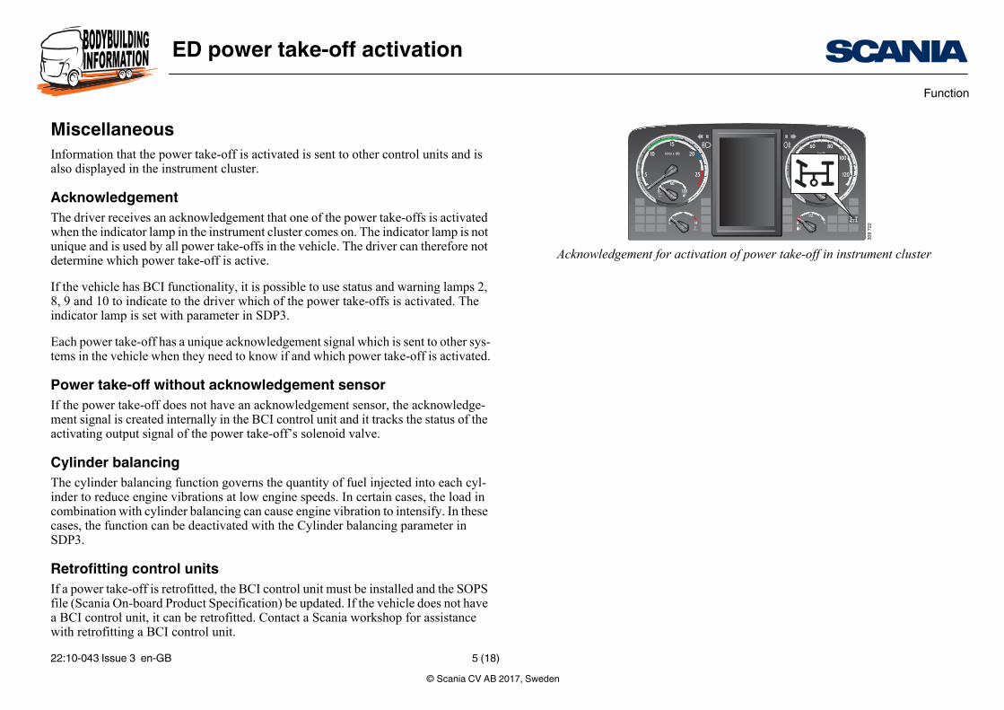
Acknowledgement for activation of power take-off in instrument cluster
MiscellaneousInformation that the power take-off is activated is sent to other control units and is also displayed in the instrument cluster.
AcknowledgementThe driver receives an acknowledgement that one of the power take-offs is activated when the indicator lamp in the instrument cluster comes on. The indicator lamp is not unique and is used by all power take-offs in the vehicle. The driver can therefore not determine which power take-off is active.
If the vehicle has BCI functionality, it is possible to use status and warning lamps 2, 8, 9 and 10 to indicate to the driver which of the power take-offs is activated. The indicator lamp is set with parameter in SDP3.
Each power take-off has a unique acknowledgement signal which is sent to other sys-tems in the vehicle when they need to know if and which power take-off is activated.
Power take-off without acknowledgement sensorIf the power take-off does not have an acknowledgement sensor, the acknowledge-ment signal is created internally in the BCI control unit and it tracks the status of the activating output signal of the power take-off’s solenoid valve.
Cylinder balancingThe cylinder balancing function governs the quantity of fuel injected into each cyl-inder to reduce engine vibrations at low engine speeds. In certain cases, the load in combination with cylinder balancing can cause engine vibration to intensify. In these cases, the function can be deactivated with the Cylinder balancing parameter in SDP3.
Retrofitting control unitsIf a power take-off is retrofitted, the BCI control unit must be installed and the SOPS file (Scania On-board Product Specification) be updated. If the vehicle does not have a BCI control unit, it can be retrofitted. Contact a Scania workshop for assistance with retrofitting a BCI control unit.
© Scania CV AB 2017, Sweden22:10-043 Issue 3 en-GB 5 (18)
ED power take-off activationFunction
Double ED power take-offsThe vehicle must either be ordered with an ED power take-off with 2 electrical con-nections from the factory or the control units must be reprogrammed via an update of SOPS during retrofitting.
© Scania CV AB 2017, Sweden22:10-043 Issue 3 en-GB 6 (18)
ED power take-off activationChassis conditions
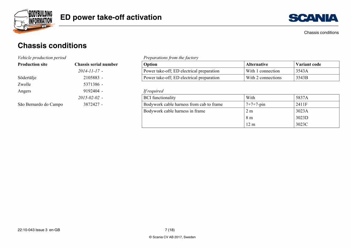
the factory
Alternative Variant code
D electrical preparation With 1 connection 3543A
D electrical preparation With 2 connections 3543B
With 5837A
arness from cab to frame 7+7+7-pin 2411F
arness in frame 2 m 3023A
8 m 3023D
12 m 3023C
Chassis conditionsVehicle production period Preparations from
Production site Chassis serial number Option
2014-11-17 - Power take-off; E
Södertälje 2105883 - Power take-off; E
Zwolle 5371386 -
Angers 9192404 - If required
2015-02-02 - BCI functionality
São Bernardo do Campo 3872427 - Bodywork cable h
Bodywork cable h
© Scania CV AB 2017, Sweden22:10-043 Issue 3 en-GB 7 (18)
ED power take-off activationParameters that can be adjusted using SDP3
sic setting Group
thout
Power-train
ctive when power take-off n use or the vehicle is mov-
00 rpm
tive
sic setting Group
thout Power-train
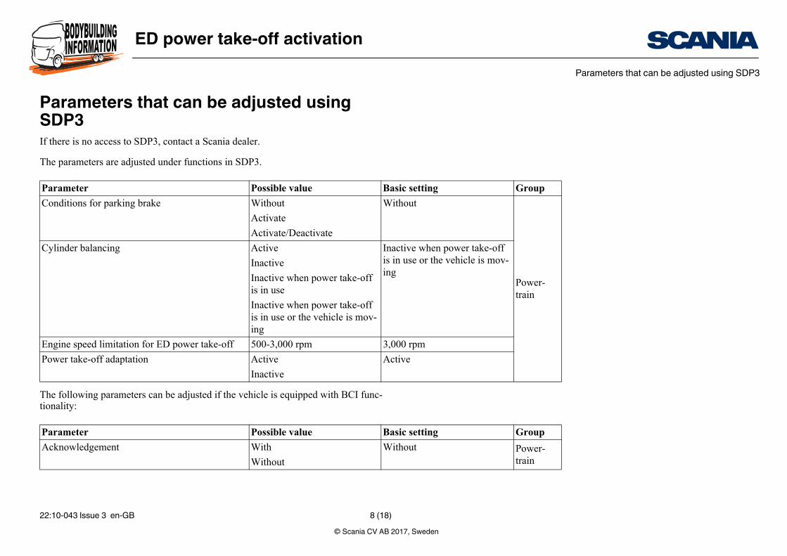
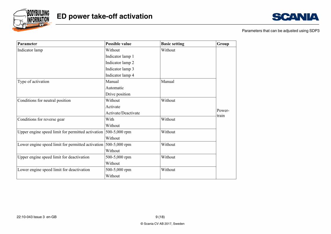
Parameters that can be adjusted using SDP3If there is no access to SDP3, contact a Scania dealer.
The parameters are adjusted under functions in SDP3.
The following parameters can be adjusted if the vehicle is equipped with BCI func-tionality:
Parameter Possible value Ba
Conditions for parking brake Without Wi
Activate
Activate/Deactivate
Cylinder balancing Active Inais iing
Inactive
Inactive when power take-off is in use
Inactive when power take-off is in use or the vehicle is mov-ing
Engine speed limitation for ED power take-off 500-3,000 rpm 3,0
Power take-off adaptation Active Ac
Inactive
Parameter Possible value Ba
Acknowledgement With Wi
Without
© Scania CV AB 2017, Sweden22:10-043 Issue 3 en-GB 8 (18)
ED power take-off activationParameters that can be adjusted using SDP3
thout
Power-train
nual
thout
thout
thout
thout
thout
thout
sic setting Group
Indicator lamp Without Wi
Indicator lamp 1
Indicator lamp 2
Indicator lamp 3
Indicator lamp 4
Type of activation Manual Ma
Automatic
Drive position
Conditions for neutral position Without Wi
Activate
Activate/Deactivate
Conditions for reverse gear With Wi
Without
Upper engine speed limit for permitted activation 500-5,000 rpm Wi
Without
Lower engine speed limit for permitted activation 500-5,000 rpm Wi
Without
Upper engine speed limit for deactivation 500-5,000 rpm Wi
Without
Lower engine speed limit for deactivation 500-5,000 rpm Wi
Without
Parameter Possible value Ba
© Scania CV AB 2017, Sweden22:10-043 Issue 3 en-GB 9 (18)
ED power take-off activationParameters that can be adjusted using SDP3
thout
Power-train
thout
thout
thout
sic setting Group
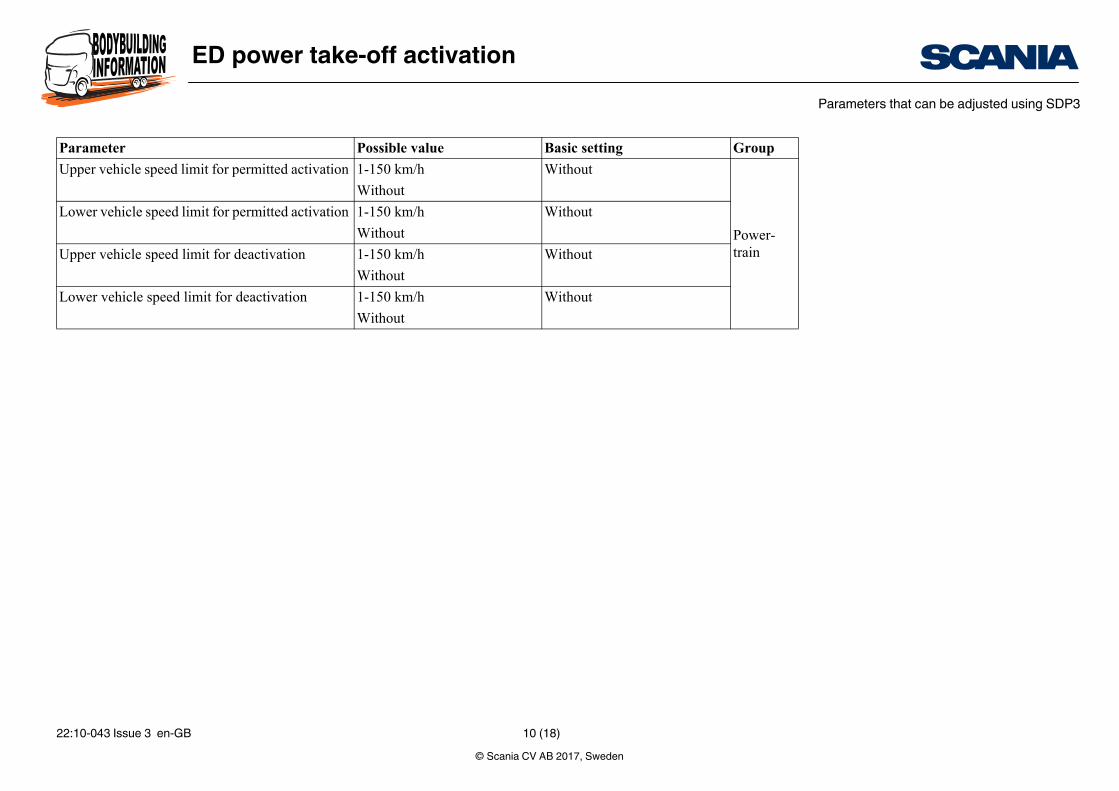
Upper vehicle speed limit for permitted activation 1-150 km/h Wi
Without
Lower vehicle speed limit for permitted activation 1-150 km/h Wi
Without
Upper vehicle speed limit for deactivation 1-150 km/h Wi
Without
Lower vehicle speed limit for deactivation 1-150 km/h Wi
Without
Parameter Possible value Ba
© Scania CV AB 2017, Sweden22:10-043 Issue 3 en-GB 10 (18)
ED power take-off activationConnecting and activating a function
BIC.
Request
Request
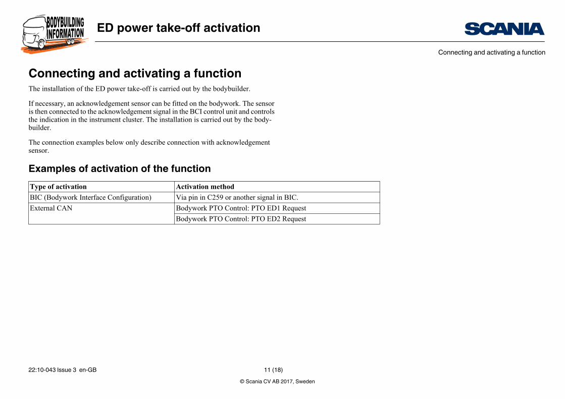
Connecting and activating a functionThe installation of the ED power take-off is carried out by the bodybuilder.
If necessary, an acknowledgement sensor can be fitted on the bodywork. The sensor is then connected to the acknowledgement signal in the BCI control unit and controls the indication in the instrument cluster. The installation is carried out by the body-builder.
The connection examples below only describe connection with acknowledgement sensor.
Examples of activation of the functionType of activation Activation method
BIC (Bodywork Interface Configuration) Via pin in C259 or another signal in
External CAN Bodywork PTO Control: PTO ED1
Bodywork PTO Control: PTO ED2
© Scania CV AB 2017, Sweden22:10-043 Issue 3 en-GB 11 (18)
ED power take-off activationConnecting and activating a function
S168/S169
C259
C259
S168
S169
V150
G2
G13
V122
1
2
350
938
V122/V150
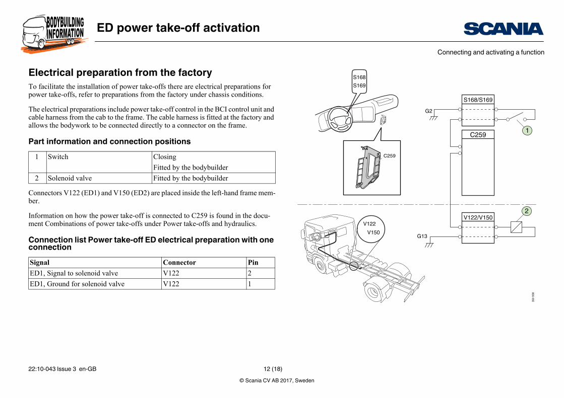
Electrical preparation from the factoryTo facilitate the installation of power take-offs there are electrical preparations for power take-offs, refer to preparations from the factory under chassis conditions.
The electrical preparations include power take-off control in the BCI control unit and cable harness from the cab to the frame. The cable harness is fitted at the factory and allows the bodywork to be connected directly to a connector on the frame.
Part information and connection positions
Connectors V122 (ED1) and V150 (ED2) are placed inside the left-hand frame mem-ber.
Information on how the power take-off is connected to C259 is found in the docu-ment Combinations of power take-offs under Power take-offs and hydraulics.
Connection list Power take-off ED electrical preparation with one connection
1 Switch Closing
Fitted by the bodybuilder
2 Solenoid valve Fitted by the bodybuilder
Signal Connector Pin
ED1, Signal to solenoid valve V122 2
ED1, Ground for solenoid valve V122 1
© Scania CV AB 2017, Sweden22:10-043 Issue 3 en-GB 12 (18)
ED power take-off activationConnecting and activating a function
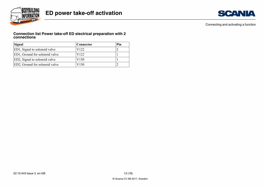
Connection list Power take-off ED electrical preparation with 2 connectionsSignal Connector Pin
ED1, Signal to solenoid valve V122 2
ED1, Ground for solenoid valve V122 1
ED2, Signal to solenoid valve V150 1
ED2, Ground for solenoid valve V150 2
© Scania CV AB 2017, Sweden22:10-043 Issue 3 en-GB 13 (18)
ED power take-off activationConnecting and activating a function
1
BCI
2
3
350
550
C259+24 V
5
4
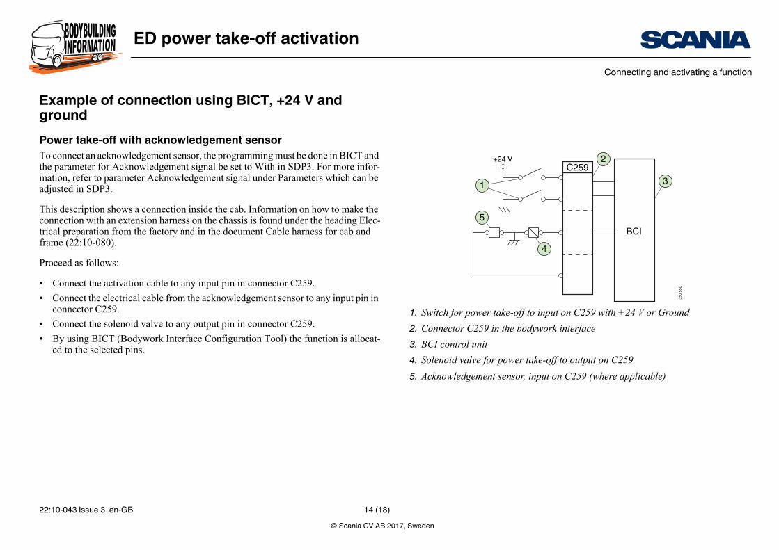
1. Switch for power take-off to input on C259 with +24 V or Ground
2. Connector C259 in the bodywork interface
3. BCI control unit
4. Solenoid valve for power take-off to output on C259
5. Acknowledgement sensor, input on C259 (where applicable)
Example of connection using BICT, +24 V and groundPower take-off with acknowledgement sensorTo connect an acknowledgement sensor, the programming must be done in BICT and the parameter for Acknowledgement signal be set to With in SDP3. For more infor-mation, refer to parameter Acknowledgement signal under Parameters which can be adjusted in SDP3.
This description shows a connection inside the cab. Information on how to make the connection with an extension harness on the chassis is found under the heading Elec-trical preparation from the factory and in the document Cable harness for cab and frame (22:10-080).
Proceed as follows:
• Connect the activation cable to any input pin in connector C259.
• Connect the electrical cable from the acknowledgement sensor to any input pin in connector C259.
• Connect the solenoid valve to any output pin in connector C259.
• By using BICT (Bodywork Interface Configuration Tool) the function is allocat-ed to the selected pins.
© Scania CV AB 2017, Sweden22:10-043 Issue 3 en-GB 14 (18)
ED power take-off activationConnecting and activating a function
C259 pin (1–10),High or low
C259 pin (11–16)Power take-off withacknowledgment
C259 pin (1–10),High or low
350
657
1
4
2 3
BCI
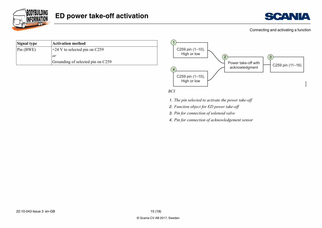
1. The pin selected to activate the power take-off
2. Function object for ED power take-off
3. Pin for connection of solenoid valve
4. Pin for connection of acknowledgement sensor
Signal type Activation method
Pin (BWE) +24 V to selected pin on C259
or
Grounding of selected pin on C259
© Scania CV AB 2017, Sweden22:10-043 Issue 3 en-GB 15 (18)
ED power take-off activationConnecting and activating a function
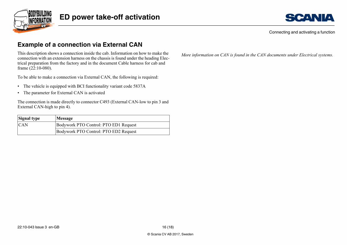
More information on CAN is found in the CAN documents under Electrical systems.
Example of a connection via External CANThis description shows a connection inside the cab. Information on how to make the connection with an extension harness on the chassis is found under the heading Elec-trical preparation from the factory and in the document Cable harness for cab and frame (22:10-080).
To be able to make a connection via External CAN, the following is required:
• The vehicle is equipped with BCI functionality variant code 5837A
• The parameter for External CAN is activated
The connection is made directly to connector C493 (External CAN-low to pin 3 and External CAN-high to pin 4).
Signal type Message
CAN Bodywork PTO Control: PTO ED1 Request
Bodywork PTO Control: PTO ED2 Request
© Scania CV AB 2017, Sweden22:10-043 Issue 3 en-GB 16 (18)
ED power take-off activationConnecting and activating a function
BCI
3
4
6
350
604
1
C493
CAN
2
5C259
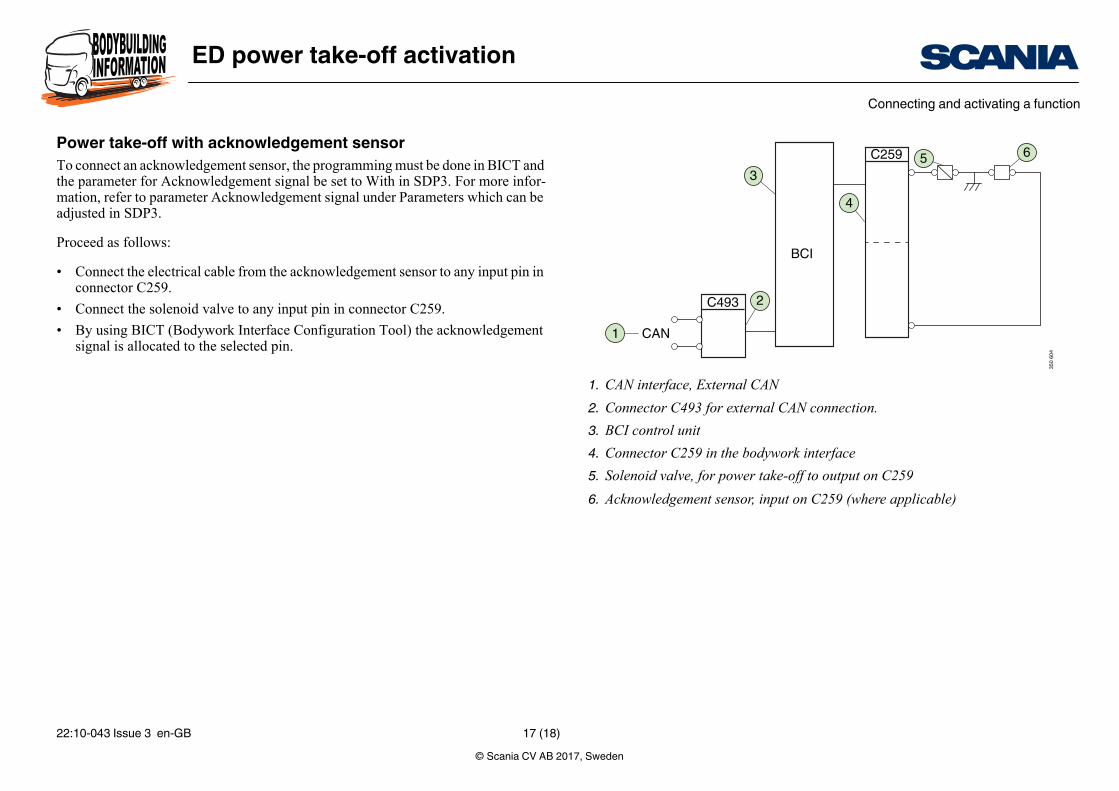
1. CAN interface, External CAN
2. Connector C493 for external CAN connection.
3. BCI control unit
4. Connector C259 in the bodywork interface
5. Solenoid valve, for power take-off to output on C259
6. Acknowledgement sensor, input on C259 (where applicable)
Power take-off with acknowledgement sensorTo connect an acknowledgement sensor, the programming must be done in BICT and the parameter for Acknowledgement signal be set to With in SDP3. For more infor-mation, refer to parameter Acknowledgement signal under Parameters which can be adjusted in SDP3.
Proceed as follows:
• Connect the electrical cable from the acknowledgement sensor to any input pin in connector C259.
• Connect the solenoid valve to any input pin in connector C259.
• By using BICT (Bodywork Interface Configuration Tool) the acknowledgement signal is allocated to the selected pin.
© Scania CV AB 2017, Sweden22:10-043 Issue 3 en-GB 17 (18)
ED power take-off activationConnecting and activating a function
C259 pin (11–16)Power take-off withacknowledgment
350
674
2 3
C259 pin (1–10),High or low
1
BCI
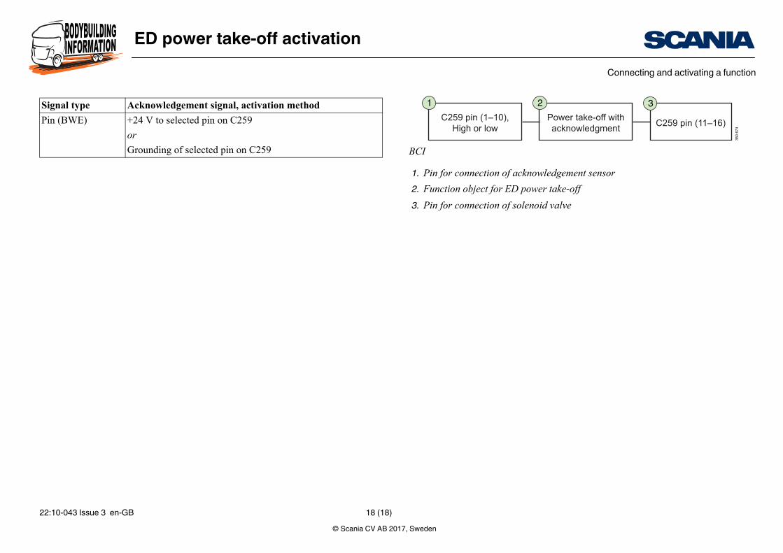
1. Pin for connection of acknowledgement sensor
2. Function object for ED power take-off
3. Pin for connection of solenoid valve
Signal type Acknowledgement signal, activation method
Pin (BWE) +24 V to selected pin on C259
or
Grounding of selected pin on C259
© Scania CV AB 2017, Sweden22:10-043 Issue 3 en-GB 18 (18)