9 power take-off - ddcsn - detroit diesel … power take-off section page 9.1 rear engine power...
TRANSCRIPT
9 POWER TAKE-OFF
Section Page
9.1 REAR ENGINE POWER TAKE-OFF (REPTO) ASSEMBLY .................... 9-39.2 FRONT MOUNTED POWER TAKE-OFF ................................................. 9-25

All information subject to change without notice.9-2 From Bulletin 4-50-02 6SE50 0006 Copyright © 2002 DETROIT DIESEL CORPORATION
SERIES 50 SERVICE MANUAL
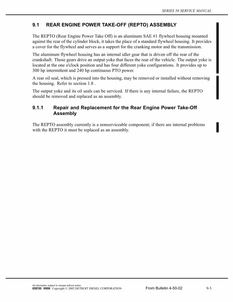
9.1 REAR ENGINE POWER TAKE-OFF (REPTO) ASSEMBLY
The REPTO (Rear Engine Power Take Off) is an aluminum SAE #1 flywheel housing mountedagainst the rear of the cylinder block, it takes the place of a standard flywheel housing. It providesa cover for the flywheel and serves as a support for the cranking motor and the transmission.
The aluminum flywheel housing has an internal idler gear that is driven off the rear of thecrankshaft. Those gears drive an output yoke that faces the rear of the vehicle. The output yoke islocated at the one o'clock position and has four different yoke configurations. It provides up to300 hp intermittent and 240 hp continuous PTO power.
A rear oil seal, which is pressed into the housing, may be removed or installed without removingthe housing. Refer to section 1.8 .
The output yoke and its oil seals can be serviced. If there is any internal failure, the REPTOshould be removed and replaced as an assembly.
9.1.1 Repair and Replacement for the Rear Engine Power Take-OffAssembly
The REPTO assembly currently is a nonserviceable component; if there are internal problemswith the REPTO it must be replaced as an assembly.
All information subject to change without notice.6SE50 0006 Copyright © 2002 DETROIT DIESEL CORPORATION From Bulletin 4-50-02 9-3
9.1 REAR ENGINE POWER TAKE-OFF (REPTO) ASSEMBLY
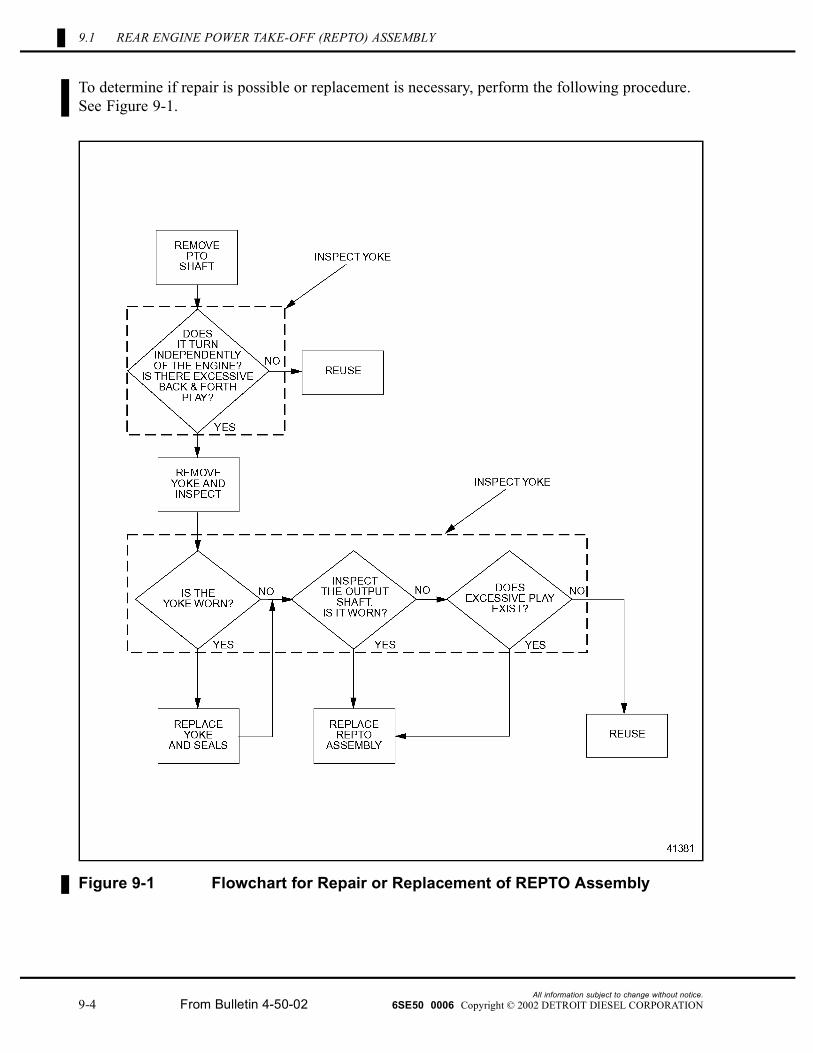
To determine if repair is possible or replacement is necessary, perform the following procedure.See Figure 9-1.
Figure 9-1 Flowchart for Repair or Replacement of REPTO Assembly
All information subject to change without notice.9-4 From Bulletin 4-50-02 6SE50 0006 Copyright © 2002 DETROIT DIESEL CORPORATION
SERIES 50 SERVICE MANUAL
9.1.2 Removal of Rear Engine Power Take-off Assembly
Remove the REPTO assembly as follows:
1. Disconnect battery power. Refer to section 8.3.2 .
2. Remove cranking motor from the REPTO flywheel housing. Refer to section 8.5.2 .
3. Remove transmission and PTO driveshaft and any other parts attached to the housing.
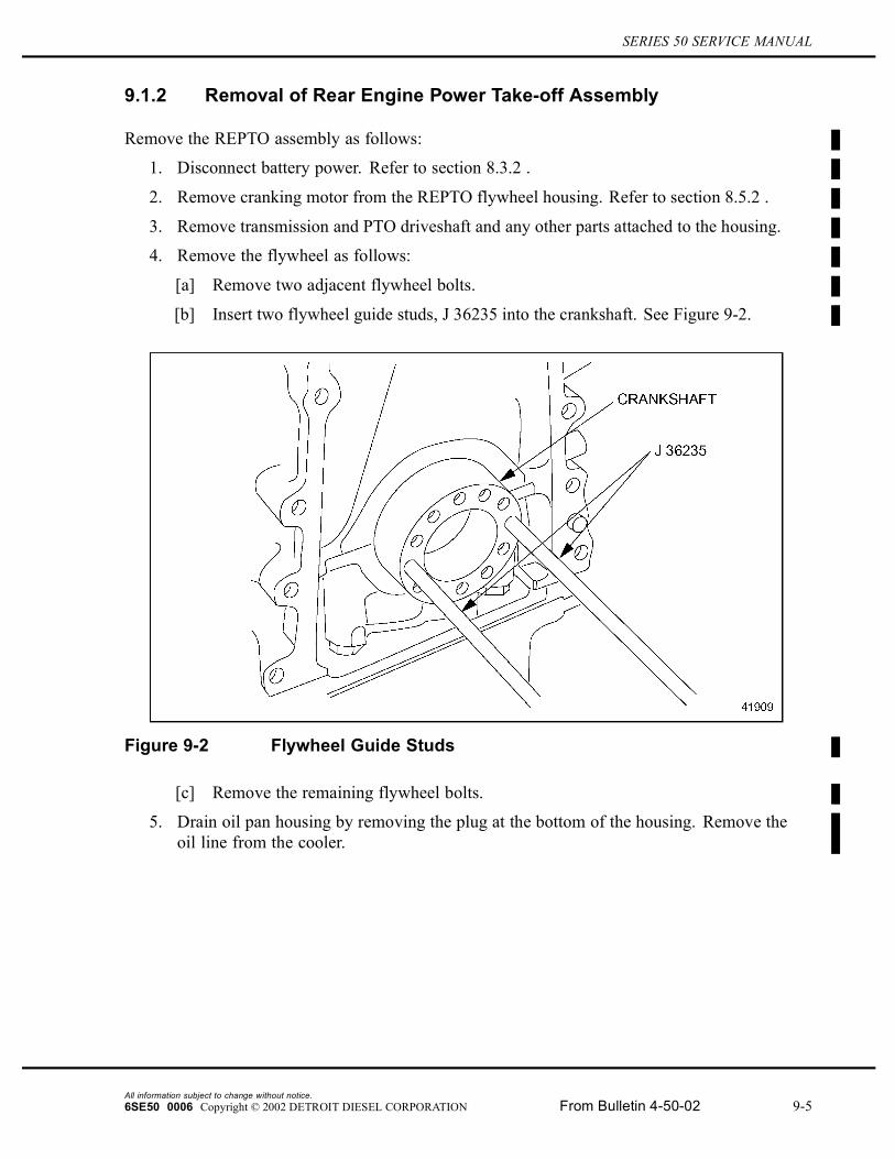
4. Remove the flywheel as follows:
[a] Remove two adjacent flywheel bolts.
[b] Insert two flywheel guide studs, J 36235 into the crankshaft. See Figure 9-2.
Figure 9-2 Flywheel Guide Studs
[c] Remove the remaining flywheel bolts.
5. Drain oil pan housing by removing the plug at the bottom of the housing. Remove theoil line from the cooler.
All information subject to change without notice.6SE50 0006 Copyright © 2002 DETROIT DIESEL CORPORATION From Bulletin 4-50-02 9-5
9.1 REAR ENGINE POWER TAKE-OFF (REPTO) ASSEMBLY
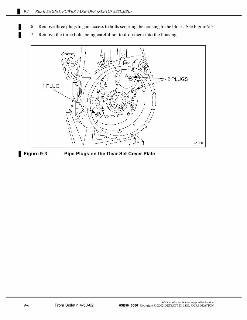
6. Remove three plugs to gain access to bolts securing the housing to the block. See Figure 9-3
7. Remove the three bolts being careful not to drop them into the housing.
Figure 9-3 Pipe Plugs on the Gear Set Cover Plate
All information subject to change without notice.9-6 From Bulletin 4-50-02 6SE50 0006 Copyright © 2002 DETROIT DIESEL CORPORATION
SERIES 50 SERVICE MANUAL
NOTICE:Do not drop the bolt or washer into the gear set. Engine orREPTO damage will occur.
8. Remove the remaining eight bolts.
To avoid injury from a falling component while using alifting device, never stand beneath a suspended load.
9. Attach a suitable sling or use a floor jack to support the flywheel housing, which weighsabout 120 lbs. Gently tap the backside of the flywheel housing with a rubber mallet toloosen it from the block. Remove the housing.
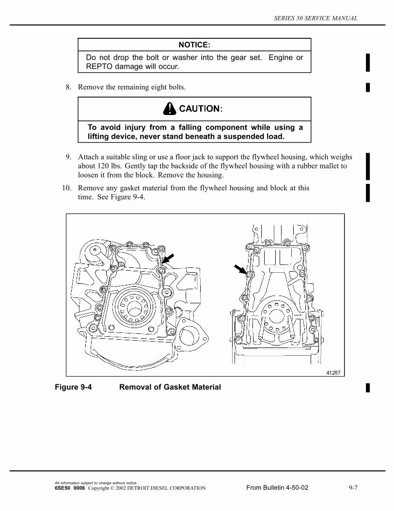
10. Remove any gasket material from the flywheel housing and block at thistime. See Figure 9-4.
Figure 9-4 Removal of Gasket Material
All information subject to change without notice.6SE50 0006 Copyright © 2002 DETROIT DIESEL CORPORATION From Bulletin 4-50-02 9-7
9.1 REAR ENGINE POWER TAKE-OFF (REPTO) ASSEMBLY
To avoid injury from flying sealant. Do not use an impactgun on plugs with white sealant.
11. Remove all sealing material from the block and housing. Refer to Section on “Cleaning”in the “General Information Section”.
9.1.3 Cleaning of Rear Engine Power Take-off Assembly
Clean the REPTO as follows:
1. Clean any residue from the end of the crankshaft and inside wall of the REPTO mountinghub.
2. Clean any residue from the yoke sealing surface, washer and nut.
9.1.3.1 Inspection of Rear Engine Power Take-off Assembly
Inspect the REPTO assembly as follows:
1. Inspect the flywheel. Refer to section1.14.2.1 .
2. Inspect flywheel housing for cracks and any other damage.
[a] If sealing surface is damaged, repair with emery cloth.
[b] If cracked, repair is not possible.
3. Inspect the crankshaft where the rear oil seal makes contact. Refer to section 1.8 .
[a] Check for groove in crankshaft.
[b] If crankshaft is grooved, install a wear sleeve over the crankshaft end. An oversizedI.D. rear oil seal must be used with the rear sleeve. Refer to section 1.8.7 .
4. Inspect the bottom of the yoke.
[a] If burrs are found on the surface of the yoke, replace the component.
[b] If no damage is found, reuse part.
5. Inspect the rubber yoke seal.
[a] If any defects are found, replace the seal.
[b] If no damage is found, reuse the seal.
All information subject to change without notice.9-8 From Bulletin 4-50-02 6SE50 0006 Copyright © 2002 DETROIT DIESEL CORPORATION
SERIES 50 SERVICE MANUAL
9.1.4 Installation of Rear Engine Power Take-off Assembly
Install the REPTO as follows:
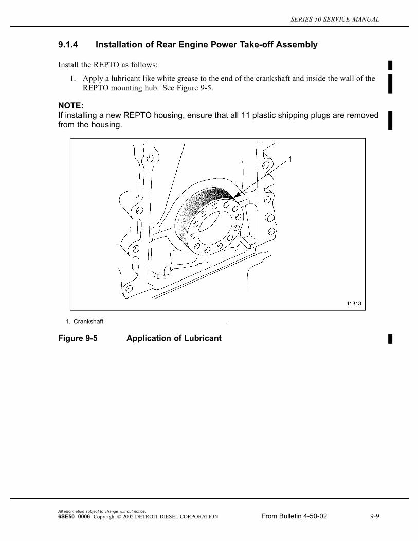
1. Apply a lubricant like white grease to the end of the crankshaft and inside the wall of theREPTO mounting hub. See Figure 9-5.
NOTE:If installing a new REPTO housing, ensure that all 11 plastic shipping plugs are removedfrom the housing.
1. Crankshaft .
Figure 9-5 Application of Lubricant
All information subject to change without notice.6SE50 0006 Copyright © 2002 DETROIT DIESEL CORPORATION From Bulletin 4-50-02 9-9
9.1 REAR ENGINE POWER TAKE-OFF (REPTO) ASSEMBLY
2. If installing a new REPTO housing:
To avoid injury from flying sealant. Do not use an impactgun on plugs with white sealant.
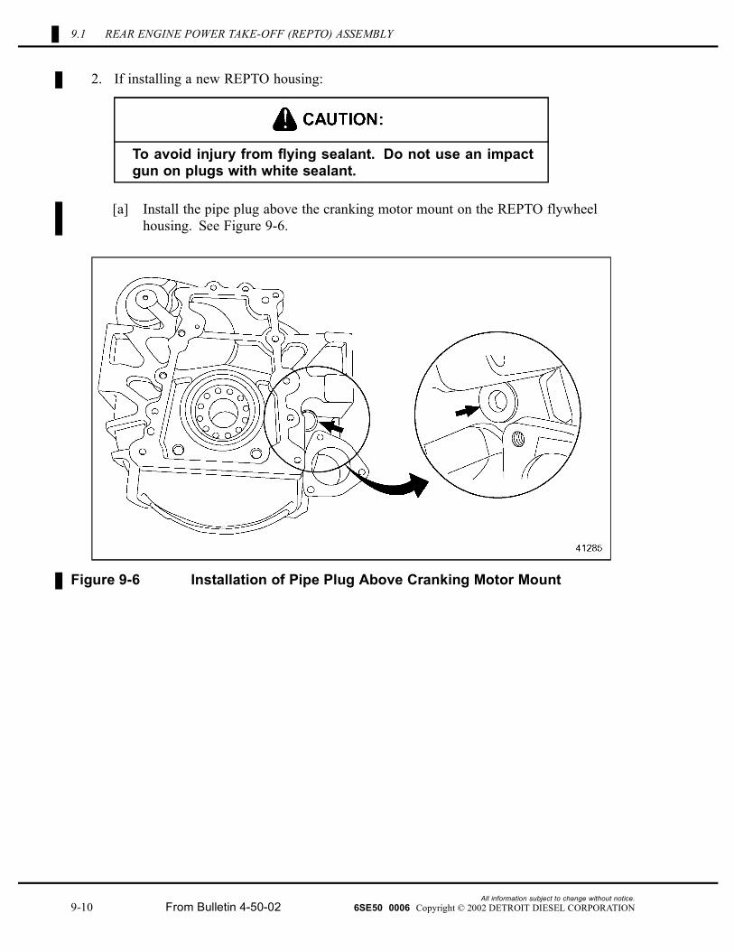
[a] Install the pipe plug above the cranking motor mount on the REPTO flywheelhousing. See Figure 9-6.
Figure 9-6 Installation of Pipe Plug Above Cranking Motor Mount
All information subject to change without notice.9-10 From Bulletin 4-50-02 6SE50 0006 Copyright © 2002 DETROIT DIESEL CORPORATION
SERIES 50 SERVICE MANUAL
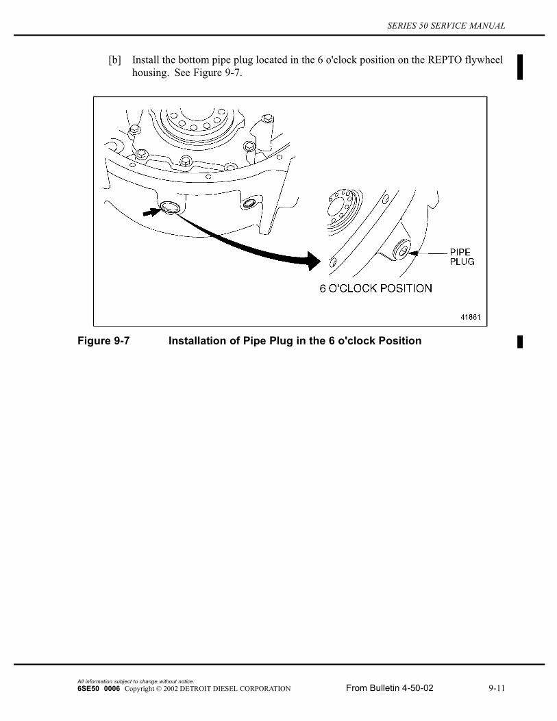
[b] Install the bottom pipe plug located in the 6 o'clock position on the REPTO flywheelhousing. See Figure 9-7.
Figure 9-7 Installation of Pipe Plug in the 6 o'clock Position
All information subject to change without notice.6SE50 0006 Copyright © 2002 DETROIT DIESEL CORPORATION From Bulletin 4-50-02 9-11
9.1 REAR ENGINE POWER TAKE-OFF (REPTO) ASSEMBLY
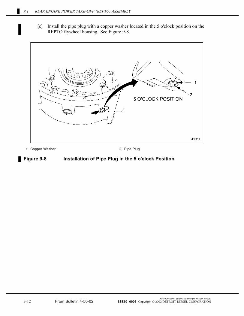
[c] Install the pipe plug with a copper washer located in the 5 o'clock position on theREPTO flywheel housing. See Figure 9-8.
1. Copper Washer 2. Pipe Plug
Figure 9-8 Installation of Pipe Plug in the 5 o'clock Position
All information subject to change without notice.9-12 From Bulletin 4-50-02 6SE50 0006 Copyright © 2002 DETROIT DIESEL CORPORATION
SERIES 50 SERVICE MANUAL
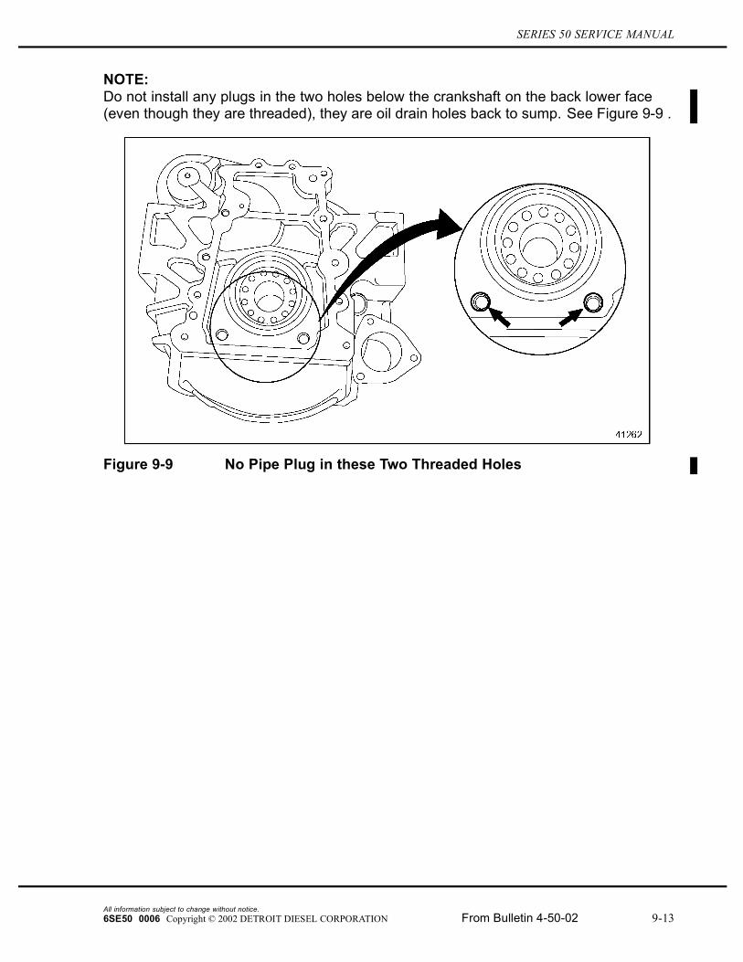
NOTE:Do not install any plugs in the two holes below the crankshaft on the back lower face(even though they are threaded), they are oil drain holes back to sump. See Figure 9-9 .
Figure 9-9 No Pipe Plug in these Two Threaded Holes
All information subject to change without notice.6SE50 0006 Copyright © 2002 DETROIT DIESEL CORPORATION From Bulletin 4-50-02 9-13
9.1 REAR ENGINE POWER TAKE-OFF (REPTO) ASSEMBLY
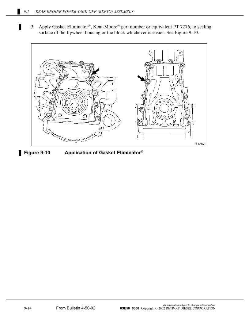
3. Apply Gasket Eliminator®, Kent-Moore® part number or equivalent PT 7276, to sealingsurface of the flywheel housing or the block whichever is easier. See Figure 9-10.
Figure 9-10 Application of Gasket Eliminator®
All information subject to change without notice.9-14 From Bulletin 4-50-02 6SE50 0006 Copyright © 2002 DETROIT DIESEL CORPORATION
SERIES 50 SERVICE MANUAL
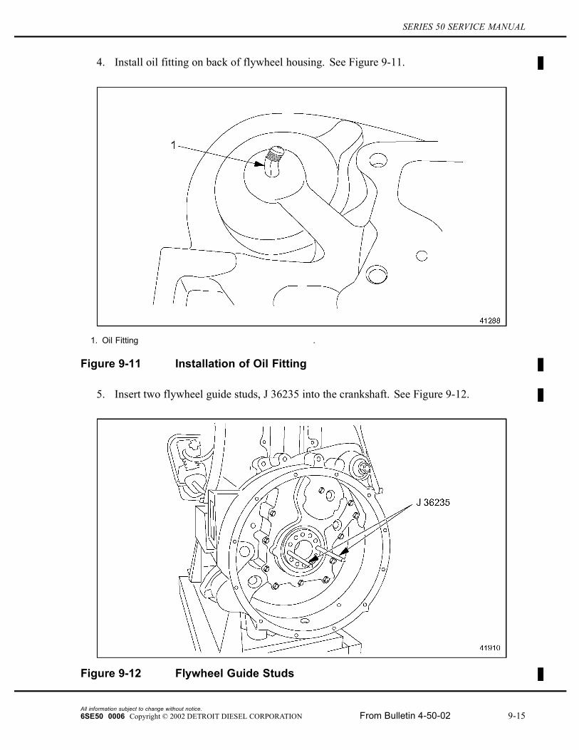
4. Install oil fitting on back of flywheel housing. See Figure 9-11.
1. Oil Fitting .
Figure 9-11 Installation of Oil Fitting
5. Insert two flywheel guide studs, J 36235 into the crankshaft. See Figure 9-12.
Figure 9-12 Flywheel Guide Studs
All information subject to change without notice.6SE50 0006 Copyright © 2002 DETROIT DIESEL CORPORATION From Bulletin 4-50-02 9-15
9.1 REAR ENGINE POWER TAKE-OFF (REPTO) ASSEMBLY
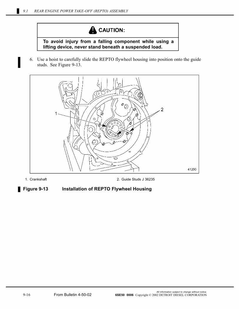
To avoid injury from a falling component while using alifting device, never stand beneath a suspended load.
6. Use a hoist to carefully slide the REPTO flywheel housing into position onto the guidestuds. See Figure 9-13.
1. Crankshaft 2. Guide Studs J 36235
Figure 9-13 Installation of REPTO Flywheel Housing
All information subject to change without notice.9-16 From Bulletin 4-50-02 6SE50 0006 Copyright © 2002 DETROIT DIESEL CORPORATION
SERIES 50 SERVICE MANUAL
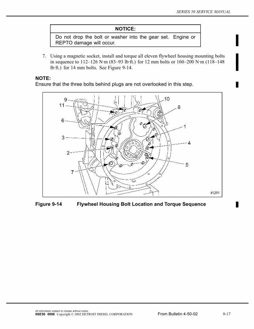
NOTICE:Do not drop the bolt or washer into the gear set. Engine orREPTO damage will occur.
7. Using a magnetic socket, install and torque all eleven flywheel housing mounting boltsin sequence to 112–126 N·m (83–93 lb·ft.) for 12 mm bolts or 160–200 N·m (118–148lb·ft.) for 14 mm bolts. See Figure 9-14.
NOTE:Ensure that the three bolts behind plugs are not overlooked in this step.
Figure 9-14 Flywheel Housing Bolt Location and Torque Sequence
All information subject to change without notice.6SE50 0006 Copyright © 2002 DETROIT DIESEL CORPORATION From Bulletin 4-50-02 9-17

9.1 REAR ENGINE POWER TAKE-OFF (REPTO) ASSEMBLY
8. Install the two pipe plugs located on the gear set cover plate and plug next to the crankingmotor. See Figure 9-15.
Figure 9-15 Pipe Plugs on the Gear Set Cover Plate
All information subject to change without notice.9-18 From Bulletin 4-50-02 6SE50 0006 Copyright © 2002 DETROIT DIESEL CORPORATION
SERIES 50 SERVICE MANUAL
9. Set crankshaft endplay as follows:
NOTICE:Setting crankshaft end play must be done whenever the REPTOhousing is installed to prevent crankshaft from damagingcrankshaft thrust washers upon initial engine startup.
[a] Bolt the flywheel to the unit using six flywheel bolts.
[b] Torque the flywheel bolts to 102 N·m (75 ft·lb).
[c] Remove the flywheel. (This is necessary to remove the gap between the crankshaftand REPTO drive hub.)
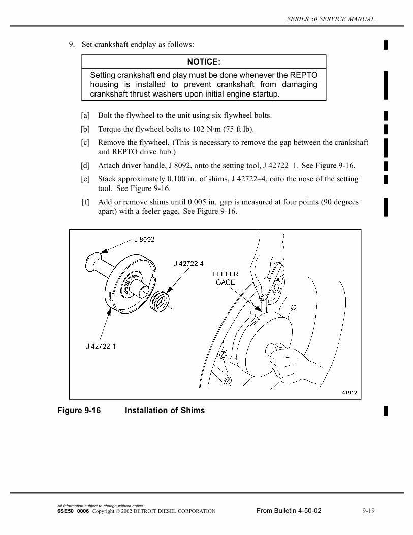
[d] Attach driver handle, J 8092, onto the setting tool, J 42722–1. See Figure 9-16.
[e] Stack approximately 0.100 in. of shims, J 42722–4, onto the nose of the settingtool. See Figure 9-16.
[f] Add or remove shims until 0.005 in. gap is measured at four points (90 degreesapart) with a feeler gage. See Figure 9-16.
Figure 9-16 Installation of Shims
All information subject to change without notice.6SE50 0006 Copyright © 2002 DETROIT DIESEL CORPORATION From Bulletin 4-50-02 9-19
9.1 REAR ENGINE POWER TAKE-OFF (REPTO) ASSEMBLY
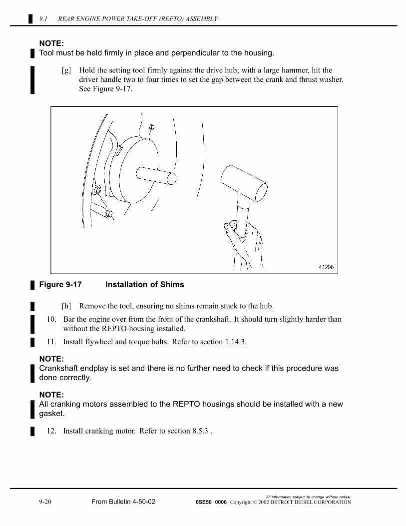
NOTE:Tool must be held firmly in place and perpendicular to the housing.
[g] Hold the setting tool firmly against the drive hub; with a large hammer, hit thedriver handle two to four times to set the gap between the crank and thrust washer.See Figure 9-17.
Figure 9-17 Installation of Shims
[h] Remove the tool, ensuring no shims remain stuck to the hub.
10. Bar the engine over from the front of the crankshaft. It should turn slightly harder thanwithout the REPTO housing installed.
11. Install flywheel and torque bolts. Refer to section 1.14.3.
NOTE:Crankshaft endplay is set and there is no further need to check if this procedure wasdone correctly.
NOTE:All cranking motors assembled to the REPTO housings should be installed with a newgasket.
12. Install cranking motor. Refer to section 8.5.3 .
All information subject to change without notice.9-20 From Bulletin 4-50-02 6SE50 0006 Copyright © 2002 DETROIT DIESEL CORPORATION
SERIES 50 SERVICE MANUAL
NOTICE:Do not connect to the wrong port. Connecting to the wrong portwill allow coolant to be fed to the gears and the engine will fail.
NOTE:Ensure the oil supply line is connected to the port next to the turbo oil supply line andnot to the oil cooler assembly.
13. Install the oil supply line to the brass fitting on the housing and the opened port.
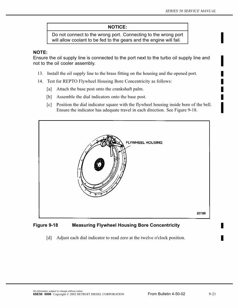
14. Test for REPTO Flywheel Housing Bore Concentricity as follows:
[a] Attach the base post onto the crankshaft palm.
[b] Assemble the dial indicators onto the base post.
[c] Position the dial indicator square with the flywheel housing inside bore of the bell.Ensure the indicator has adequate travel in each direction. See Figure 9-18.
Figure 9-18 Measuring Flywheel Housing Bore Concentricity
[d] Adjust each dial indicator to read zero at the twelve o'clock position.
All information subject to change without notice.6SE50 0006 Copyright © 2002 DETROIT DIESEL CORPORATION From Bulletin 4-50-02 9-21
9.1 REAR ENGINE POWER TAKE-OFF (REPTO) ASSEMBLY
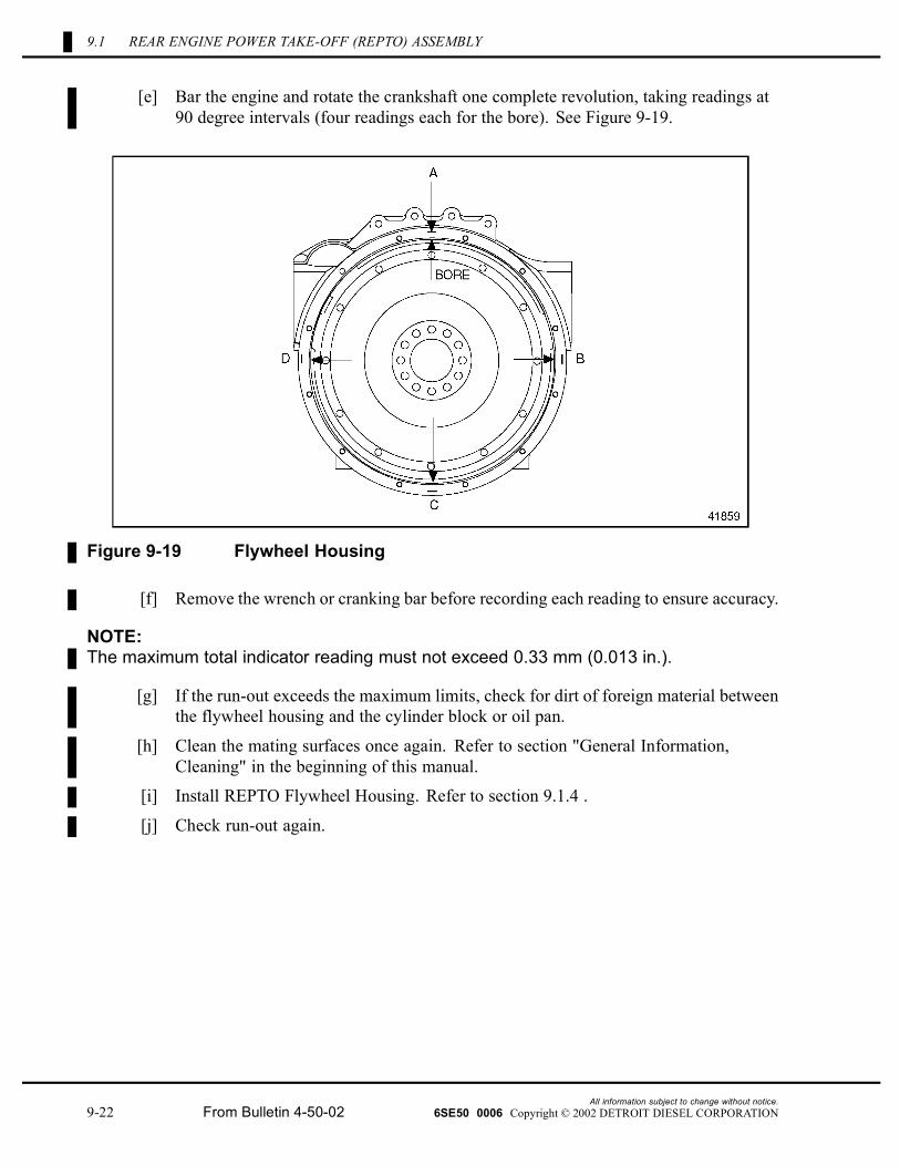
[e] Bar the engine and rotate the crankshaft one complete revolution, taking readings at90 degree intervals (four readings each for the bore). See Figure 9-19.
Figure 9-19 Flywheel Housing
[f] Remove the wrench or cranking bar before recording each reading to ensure accuracy.
NOTE:The maximum total indicator reading must not exceed 0.33 mm (0.013 in.).
[g] If the run-out exceeds the maximum limits, check for dirt of foreign material betweenthe flywheel housing and the cylinder block or oil pan.
[h] Clean the mating surfaces once again. Refer to section "General Information,Cleaning" in the beginning of this manual.
[i] Install REPTO Flywheel Housing. Refer to section 9.1.4 .
[j] Check run-out again.
All information subject to change without notice.9-22 From Bulletin 4-50-02 6SE50 0006 Copyright © 2002 DETROIT DIESEL CORPORATION
SERIES 50 SERVICE MANUAL
15. Install transmission. Refer to OEM.
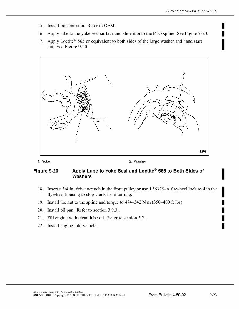
16. Apply lube to the yoke seal surface and slide it onto the PTO spline. See Figure 9-20.
17. Apply Loctite® 565 or equivalent to both sides of the large washer and hand startnut. See Figure 9-20.
1. Yoke 2. Washer
Figure 9-20 Apply Lube to Yoke Seal and Loctite® 565 to Both Sides ofWashers
18. Insert a 3/4 in. drive wrench in the front pulley or use J 36375–A flywheel lock tool in theflywheel housing to stop crank from turning.
19. Install the nut to the spline and torque to 474–542 N·m (350–400 ft lbs).
20. Install oil pan. Refer to section 3.9.3 .
21. Fill engine with clean lube oil. Refer to section 5.2 .
22. Install engine into vehicle.
All information subject to change without notice.6SE50 0006 Copyright © 2002 DETROIT DIESEL CORPORATION From Bulletin 4-50-02 9-23
9.1 REAR ENGINE POWER TAKE-OFF (REPTO) ASSEMBLY
Diesel engine exhaust and some of its constituents areknown to the State of California to cause cancer, birthdefects, and other reproductive harm.� Always start and operate an engine in a well ventilated
area.� If operating an engine in an enclosed area, vent the
exhaust to the outside.� Do not modify or tamper with the exhaust system or
emission control system.
23. Start and run engine for verification of proper engine operation.
All information subject to change without notice.9-24 From Bulletin 4-50-02 6SE50 0006 Copyright © 2002 DETROIT DIESEL CORPORATION

SERIES 50 SERVICE MANUAL
9.2 FRONT MOUNTED POWER TAKE-OFF
Detroit Diesel Corporation (DDC) has a front mounted PTO for use on the Series 50 engines.See Figure 9-21.
1. Retainer 4. Pulley Assembly
2. Bolt 5. Crankshaft
3. Hub Assembly
Figure 9-21 Front Mounted Power Take-off Components
All information subject to change without notice.6SE50 0006 Copyright © 2002 DETROIT DIESEL CORPORATION From Bulletin 4-50-02 9-25
9.2 FRONT MOUNTED POWER TAKE-OFF
This PTO is available in two different models, adaptable to Spicer 1310 and Spicer 1350 driveshafts depending on the torque and horsepower requirements. Maximum torque and horsepowerfor the PTO assemblies are listed in Table 9-1.
Power Take-off Models Engine Speed Torque HorsepowerSpicer 1310 1800 r/min 162.7 N·m (120 lb·ft) 30.6 kW (41 hp)
Spicer 1310 2100 r/min 158.7 N·m (117 lb·ft) 29.8 kW (40 hp)
Spicer 1350 1800 r/min 261.7 N·m (193 lb·ft) 57.4 kW (77 hp)
Spicer 1350 2100 r/min 253.6 N·m (187 lb·ft) 56.0 kW (75 hp)
Table 9-1 Torque and Horsepower for the Front Mounted Power Take-offAssemblies
NOTE:These torque and horsepower values are the maximum available taken at three degreesshaft angle. Any increase in the shaft angle has a direct negative effect on the amountof available torque and horsepower, as well as shaft life.
Also, any new application must have a "Torsional Analysis" performed by the DDC EngineeringDepartment.
The PTO drive shaft must be purchased through Spicer Universal Joint Division, DanaCorporation.
If a PTO adaptor kit is to be installed on an engine that has been in service it will be necessary toremove the standard pulley configuration and replace it with one of the PTO adaptor kits.
Perform the following steps to install the new PTO assembly:
1. Remove the six bolts that retain the standard crankshaft pulley; refer to Section .
2. Install the new PTO pulley; refer to Section 9.2.3. Be certain to use the new bolts andwasher provided with the PTO adaptor kit.
3. Install the new hub insulator assembly inside the new pulley assembly making certain thatthe slot on the backside of the hub fits over the dowel in the pulley.
4. Install the new 1 in.-14 x 3.50 in. bolt and retainer after coating the bolt threads andunderside of the bolt head with INTERNATIONAL COMPOUND #2®. Torque the boltto 610 N·m (450 lb·ft).
9.2.1 Repair and Replacement of the Front Mounted Power Take-offAssembly
The front mounted power take-off assembly is a nonserviceable component, tag for remanufacture.
9.2.2 Removal of the Front Mounted Power Take-off
Perform the following steps to remove the PTO assembly:
All information subject to change without notice.9-26 From Bulletin 4-50-02 6SE50 0006 Copyright © 2002 DETROIT DIESEL CORPORATION
SERIES 50 SERVICE MANUAL
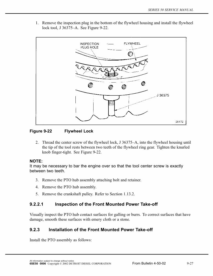
1. Remove the inspection plug in the bottom of the flywheel housing and install the flywheellock tool, J 36375–A. See Figure 9-22.
Figure 9-22 Flywheel Lock
2. Thread the center screw of the flywheel lock, J 36375–A, into the flywheel housing untilthe tip of the tool rests between two teeth of the flywheel ring gear. Tighten the knurledknob finger-tight. See Figure 9-22.
NOTE:It may be necessary to bar the engine over so that the tool center screw is exactlybetween two teeth.
3. Remove the PTO hub assembly attaching bolt and retainer.
4. Remove the PTO hub assembly.
5. Remove the crankshaft pulley. Refer to Section 1.13.2.
9.2.2.1 Inspection of the Front Mounted Power Take-off
Visually inspect the PTO hub contact surfaces for galling or burrs. To correct surfaces that havedamage, smooth these surfaces with emery cloth or a stone.
9.2.3 Installation of the Front Mounted Power Take-off
Install the PTO assembly as follows:
All information subject to change without notice.6SE50 0006 Copyright © 2002 DETROIT DIESEL CORPORATION From Bulletin 4-50-02 9-27
9.2 FRONT MOUNTED POWER TAKE-OFF
1. If removed, install flywheel locking tool J 36375–A through the inspection plug hole inthe bottom of the flywheel housing. See Figure 9-22.
2. Install the crankshaft pulley. Refer to Section 1.13.3.
3. Install the PTO hub assembly inside of the crankshaft pulley making sure the slot on thebackside of the hub fits over the dowel in the pulley.
4. Install the PTO hub assembly attaching bolt and retainer after coating the bolts threadsand underside of the bolt head with INTERNATIONAL COMPOUND #2® or equivalent.Torque the bolt to 610 N·m (450 lb·ft).
All information subject to change without notice.9-28 From Bulletin 4-50-02 6SE50 0006 Copyright © 2002 DETROIT DIESEL CORPORATION