edesigning automated guided vehiclesceas.uc.edu/content/dam/ceas/documents/uc center for...
TRANSCRIPT

eDesigning Automated Guided Vehicles
A thesis submitted to the
Division of Graduate studies and Research
of the University of Cincinnati
in partial fulfillment of the
requirements for the degree of
Master of Science
in the Department of Mechanical, Industrial and Nuclear Engineering
of the College of Engineering
1999
by
Karthikeyan Kumaraguru
B.Eng., (Production Engineering), Govt. College of Technology, India., 1996
Thesis Advisor and Committee Chair:
Dr. Ernest L. Hall
1
ABSTRACT
eDesign is a concept that is achieved when an expert system is embedded on an
network; which enables a client to design machines or products as and how they
want.
The purpose of this thesis is to describe a network based expert system to
design the base of an automated guided vehicle. The components of the expert
system include:
• A user-friendly graphic user input interface (developed in Microsoft Visual
Basic 6.0) which uses Internet Explorer 4.0 as simple client, where the user
can enter specifications – like the environment used, application of the robot,
etc. and obtain a GUI based robot design;
• A design engine that converts the managerial requirements into technical
parameters and designs the robot - initially assuming some parameters and
confirming its assumptions during the course of the design; when unable to
do so, iterating with different assumptions until they are met; the code also
selects various materials to be used from a corresponding database;
• A database of various materials from their manufacturers/suppliers - Back
end support in Microsoft SQL Server 7.0;
2
• A comprehensive “Bill of Materials” and design file is generated as the output
and suggestions for how to assemble them are given. The design when
compared with known data of Bearcat II returned list of products with 70%
accuracy. Further refinement of the logic, supported with a real time
database from vendors will reflect in the increase of the design accuracy.
The software provides an excellent tool to develop a mobile robot based on
performance specifications and the bill of materials – along with the vendor
address, helps the user buy the components needed to assemble the robot.
The significance of this development is the speed with which the design can be
converted into a product. As the results gives the Bill of Materials of off-the-shelf
products, the products can be purchased from the respective vendors and
assembled.
Keywords: Expert system, automated design, solid modeling, mobile robots.
3

4
ACKNOWLEDGEMENTS
This effort is an extension of the work of various students who have worked on
BEARCAT I and BEARCAT II robotic vehicles, at the University of Cincinnati.
This work could not have been realized without the hands of previous team
members in, David Perdue, Bradley Matthews, Tayib Samu, Alan Lewis, Malik
Spencer, Sanjeev Gupta, Todd Brehem, Randy Smith, Rob Hick, Kalyan Kolli,
Nathan Mundhenk, Nikhil Kelkar, Raymond Ande and Krishna Mohan Kola.
I also wish to thank the current team members, Ming Cao, Jin Cao, Jon Price,
Mike Rivett, Sherry Liao, Sameer Parasnis, Ramesh Thyagarajan, Sampath
Kanakaraju, Satish Shamugasundaram and Bob Roth for their enthusiasm and
encouragement that helped me finish this project
I also wish to thank all the companies that supported us with their catalogs and
especially the 80-20 Structural Kit for their AutoCAD library without which the
robot would not have been possible. We also wish to thank our sponsors whose
contributions enabled us to build the new robot.
5
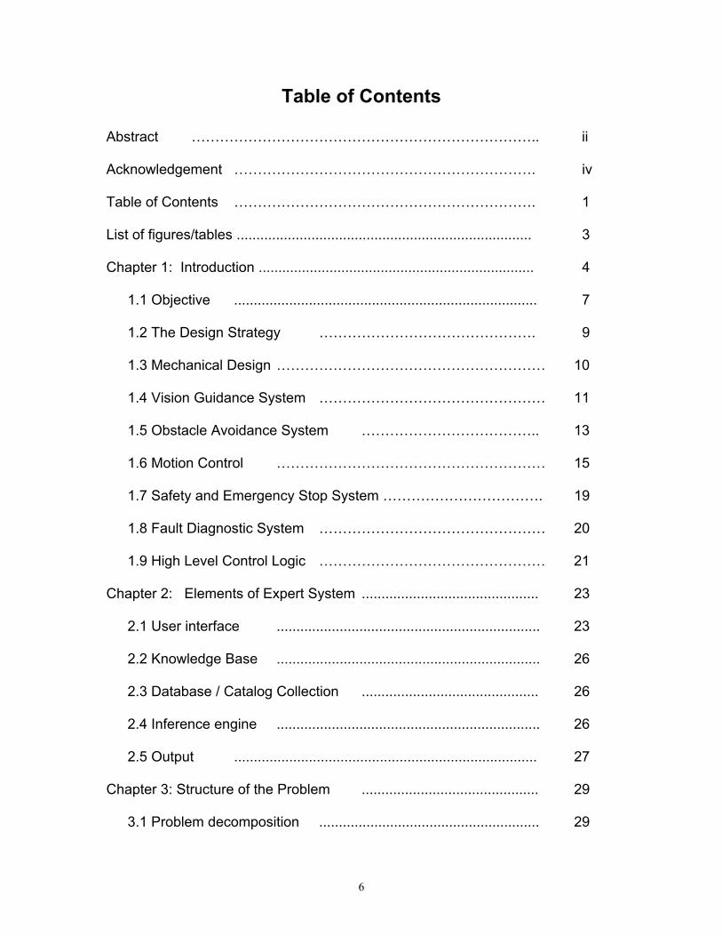
Table of Contents
Abstract ……………………………………………………………….. ii
Acknowledgement ………………………………………………………. iv
Table of Contents ………………………………………………………. 1
List of figures/tables ........................................................................... 3
Chapter 1: Introduction ...................................................................... 4
1.1 Objective ............................................................................. 7
1.2 The Design Strategy ………………………………………. 9
1.3 Mechanical Design ………………………………………………… 10
1.4 Vision Guidance System ………………………………………… 11
1.5 Obstacle Avoidance System ……………………………….. 13
1.6 Motion Control ………………………………………………… 15
1.7 Safety and Emergency Stop System ……………………………. 19
1.8 Fault Diagnostic System ………………………………………… 20
1.9 High Level Control Logic ………………………………………… 21
Chapter 2: Elements of Expert System ............................................. 23
2.1 User interface ................................................................... 23
2.2 Knowledge Base ................................................................... 26
2.3 Database / Catalog Collection ............................................. 26
2.4 Inference engine ................................................................... 26
2.5 Output ............................................................................. 27
Chapter 3: Structure of the Problem ............................................. 29
3.1 Problem decomposition ........................................................ 29
6
3.2 Sub-classification to component level ................................... 32
3.3 Identification of design parameters ................................... 33
3.4 Product selection ................................................................... 34
3.5 Bill of material generation ........................................................ 35
Chapter 4: Why Visual Basic? ............................................................. 36
4.1.1 Procedural applications ......................................................... 37
4.1.2 Event driven applications .............................................. 37
4.2 Data providers .................................................................... 38
4.3 Data Consumers …………………………………………………… 39
4.4 Service components ................................................................. 39
4.5 ADO Overview ................................................................. 40
4.6 OLE DB Data providers ........................................................... 41
4.7 Advantages .............................................................................. 42
Chapter 5: Abstract Algorithm of the Design ................................... 44
Chapter 6: Results .............................................................................. 50
Chapter 7: Conclusion and Recommendations ................................... 52
References and Bibliography ..........………………........................ 54
Appendix 1: C++ Source Code Listing of the control software ............ 56
Appendix 2: Visual Basic 6.0 Source Code ………………..……… 68
Appendix 3: AutoCAD and 80/20 Drawings ……………………..……..
Appendix 4: Database Schema ………………………………………
References and Bibliography ………………………………………
7
List of Tables/Figures
Figure 1.0: Major Sub-Systems ..........................................………… 9
Figure 2.0: Flowchart of Vision Algorithm .................................. 13
Figure 3.0: Simulink Model .....................………....................... 18
Figure 4.0: Screen Shot of Expert System .................................. 24
Figure 5.0: Detailed Screen Shot of Expert System ....................... 25
Figure 6.0: Sample BOM of the Expert System ................................. 28
Figure 7.0: Block Diagram of Robot Components............................... 30
Figure 8.0: Product Selection Logic ............................................ 31
Figure 9.0: Event Driven Code ............................………............... 37
Figure 10.0: OLEDB Components ............................................ 38
Figure 11.0 Employee Illustration ………………………………………. 42
Figure 12.0: The 3-D Model of the Robot ................................. 51
Figure 13.0: The Actual Robot …………...........................……….. 51
8
Chapter 1
INTRODUCTION
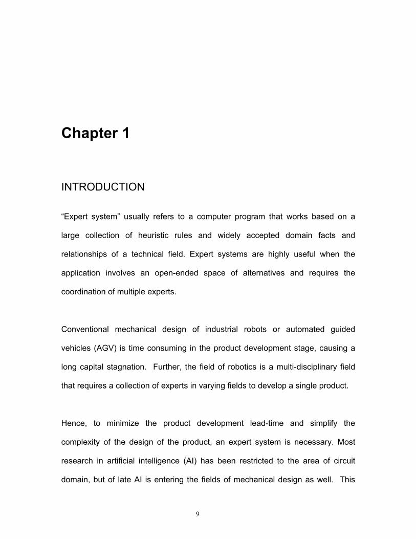
“Expert system” usually refers to a computer program that works based on a
large collection of heuristic rules and widely accepted domain facts and
relationships of a technical field. Expert systems are highly useful when the
application involves an open-ended space of alternatives and requires the
coordination of multiple experts.
Conventional mechanical design of industrial robots or automated guided
vehicles (AGV) is time consuming in the product development stage, causing a
long capital stagnation. Further, the field of robotics is a multi-disciplinary field
that requires a collection of experts in varying fields to develop a single product.
Hence, to minimize the product development lead-time and simplify the
complexity of the design of the product, an expert system is necessary. Most
research in artificial intelligence (AI) has been restricted to the area of circuit
domain, but of late AI is entering the fields of mechanical design as well. This
9

paper attempts to extend the frontiers of AI into the design of automated guided
vehicles, banking on the experience of the authors in the development of the
automated guided vehicle “Bearcat”.
The use of expert systems in mechanical design automation has been analyzed
extensively T. A. Nguyen, T. C. Young, W. A. Perkins, T. J. Laffey and D.
Pecora1. They are referred as automatic consulting systems, simulating the role
of an expert in solving problems. These expert systems have been successfully
used in a number of applications in the industry to troubleshoot various problems
or breakdowns.
Expert systems for selection of materials or design of mechanical components
have been in use for quite some time now. N. Ramachandran, et al.2, have
analyzed the expert system approach in design of mechanical components.
They have developed a design process that can be summarized as refinement
and constraint propagation and parameter selection.
A knowledge-based systems approach to design mechanical springs has been
developed by K. K. Tai, et al.3 Other literature that inspired us in our approach
was the integrated gearbox design developed by K. Mehdi. and D. Play.4 The
decomposition of a mechanical system into manageable units, and later, taking
on the design of individual units, is explained by Meunier5.
10
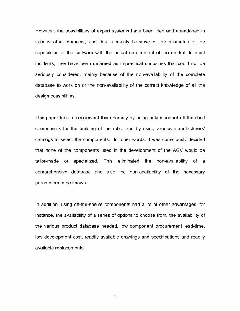
However, the possibilities of expert systems have been tried and abandoned in
various other domains, and this is mainly because of the mismatch of the
capabilities of the software with the actual requirement of the market. In most
incidents, they have been defamed as impractical curiosities that could not be
seriously considered, mainly because of the non-availability of the complete
database to work on or the non-availability of the correct knowledge of all the
design possibilities.
This paper tries to circumvent this anomaly by using only standard off-the-shelf
components for the building of the robot and by using various manufacturers’
catalogs to select the components. In other words, it was consciously decided
that none of the components used in the development of the AGV would be
tailor-made or specialized. This eliminated the non-availability of a
comprehensive database and also the non-availability of the necessary
parameters to be known.
In addition, using off-the-shelve components had a lot of other advantages, for
instance, the availability of a series of options to choose from, the availability of
the various product database needed, low component procurement lead-time,
low development cost, readily available drawings and specifications and readily
available replacements.
11
1.1 Objective
The primary objective for developing the expert system was to enable other
universities to participate in the AUVS competition. The contest is described at
http://users.erols.com/auvsicc/. The Cincinnati Center for Robotics Research at
the University of Cincinnati has been a participant in the competition for the last 7
years. The University of Cincinnati has so far used 2 versions of their AGVs. The
first, Bearcat I, robot weighs approximately 600 lbs., and is 4 feet wide and 6 feet
long. In the 1997 competition, the track was 10 feet wide. This meant that the
space left for maneuvering was 3 feet on either side of the robot, not taking into
account any obstacles.
The Bearcat II Robot weighs approximately 450 lbs., and is 2 feet wide and 4 feet
long. In the 1998 competition, the track was 10 feet wide. This meant that the
space left for maneuvering was 4 feet on either side of the robot, not taking into
account any obstacles. The necessity to build this new Bearcat II robot was
because of the increasing difficult competition rules. Had the organizers placed
the obstacles more towards the center of the track in the 1997 competition, the
robot would have had difficulty in going around the obstacles. It would also have
probably lost sight of the track, and veered off it. Hence, the Bearcat II robot was
built smaller and also with the Zero Turning Radius (ZTR) feature which greatly
improved the maneuverability of the vehicle.
12
The robot kit is simple and easy to maintain. We used the following software
design tools:
The primary mechanical and power systems design calculations were composed
in MathCAD 6.06 under WinNT environment. When the team approved the initial
design, a 3-D solid model of the kit was developed using AutoCAD Rel. 147. After
various permutations and computations, we got the final “Bill of Material” list
through the 80/20 library8 for AutoCAD. The control system was tested using
SIMULINK9, while the vision system was calibrated using MATLAB 5.210.
The system was tuned using GALIL WSDK 4.011. The kit was also subjected to a
post design vibration analysis using IDEAS 6.012. The structure designed using
IDEAS was analyzed using Finite Element Analysis. Beam Elements have been
used to determine various stresses, moments and loads and to analyze the
behavior of the frame under these conditions. The control software “Bearcat II
Ver. 2.0” was developed in the TC++13 environment.
A fault diagnostic expert system was developed by Umesh R. Nikam and Ernie
Hall14 and another base design expert system was developed to support the
robot. These were developed using Visual Basic 6.015 supported by Microsoft
SQL Server16 in the Back-end. The Source code listing is in Appendix 2.0. The
database schema is in Appendix 6.0.
13

1.2 The Design Strategy
The design of a complex mechanical system like an automated guided vehicle
must be done by hierarchical decomposition of the design problem into simpler
units and continue this breakdown until the units reach individual component
levels. These components then can be easily designed, integrated to form major
sub-units and then, on further integration, lead to the whole system.
Our vehicle can broadly be decomposed into the following major sub-systems:
Inl
m
s
Figure 1.0 M
1
Central telligence
ajor Sub-Systems
4
Safety System
Mechanical systems
Steering & Contro
Obstacle avoidance
Vision syste
Fault Diagnosi
The main difficulty in this step is properly identifying the subgroups and isolating
them. One logical approach is to define the boundaries of the units in such a
way that they would have minimal causal effect on other units. That is, the
demarcation needs to be done in such a way that the dependency of the
parameters of one unit with other units should be minimal.
1.3 Mechanical Design
All of the major units of the mechanical system can be simplified into component
level units that can be designed with the help of standard design procedures;
after which they can be selected from the corresponding manufacturers’ catalog.
A safety factor of 150% was used as a standard for all the components. Once the
design was approved, a 3-D solid model was developed using the selected
components. (Note: These calculations are available at Appendix 1.0 and
http://www.eng.uc.edu/robotics)
These steps were implemented in an iterative process. If a component did not fit,
then the whole procedure was iterated again, until all of the components were
right. To aid us in this process, 80/20 Inc. gave us their library for AutoCAD 14,
with which we could easily design the body of the robot and chart its Bill of
Materials. These drawings can be found in Appendix 3.0
15
The base was also subjected to a post design vibration testing by Jaideep Karnik
and finite element analysis to study the behavior of the robot under various load
conditions using IDEAS17.
1.4 Vision Guidance System
The purpose of the vision guidance system is to obtain information from the
changing environment--the obstacle course, which is usually bounded by solid as
well as dashed lines. The robot controller then adapts to this information and
guides the robot along the obstacle course. For line tracking, two JVC CCD18
cameras are used for following the left and right lines. Only one line is followed at
a time; however, when one camera loses the line, a video switch changes the
view to the other camera.
The dual cameras can also be used for near and far tracking of the line or
simultaneous line tracking and road hazard obstacle avoidance. Another digital
camera is mounted with a 180° view fish-eye lens. The data from this would be
used in “follow the leader” special event this year.
Image processing is accomplished by the ISCAN image-tracking device19. This
device finds the centroid of the brightest or darkest region in a computer
controlled window, and returns the X, Y coordinates of its centroid and size
information of the blob. If no object is found, a loss of track (LOT) signal is
16
generated. This information is updated every 16 ms. However, the program must
wait 10 ms after moving the window to get new data.
This results in a 52 ms update time or a cycle frequency of 19.23 cycles per
second for the vision system. The cameras are angled down at 32 degrees and
panned to one direction each at 30 degrees. This setup gives a 4 ft wide view of
the ground. It looks 6 ft ahead. Once the data points are collected they are
entered into the algorithm. From these calculations the angle and distance are
then sent to the motion control sub-system.
Image co-ordinates are two-dimensional while physical co-ordinates are three-
dimensional. In an autonomous situation, the problem is to determine the three-
dimensional coordinates of a point on the line given its image coordinates. A
new algorithm was developed20 to establish the mathematical and geometrical
relationships between the physical 3-D ground coordinates of the line to follow
and its corresponding 2-D digitized image coordinates.
Figure 2 shows the flowchart for the vision algorithm. The algorithm utilizes a
calibration device to achieve system identification with respect to the global
coordinates system. From the image coordinates and the camera parameters
the physical co-ordinates are computed through a C program.
17
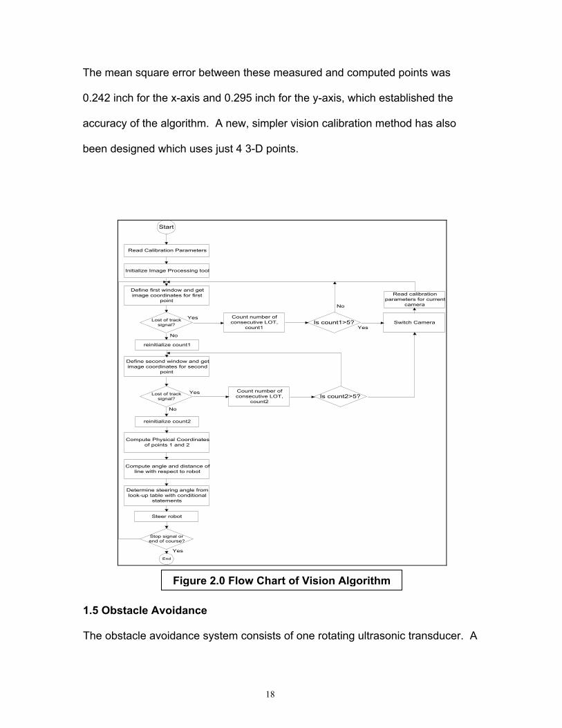
The mean square error between these measured and computed points was
0.242 inch for the x-axis and 0.295 inch for the y-axis, which established the
accuracy of the algorithm. A new, simpler vision calibration method has also
been designed which uses just 4 3-D points.
Start
Read Calibration Parameters
Is count1>5?Count number ofconsecutive LOT,
count1
Is count2>5?
Lost of tracksignal?
Lost of tracksignal?
Initialize Image Processing tool
Define first window and getimage coordinates for first
point
Define second window and getimage coordinates for second
point
Compute Physical Coordinatesof points 1 and 2
Compute angle and distance ofline with respect to robot
Determine steering angle fromlook-up table with conditional
statements
Steer robot
Stop signal orend of course?
End
Switch Camera
Count number ofconsecutive LOT,
count2
No
No
Read calibrationparameters for current
camera No
Yes
reinitialize count1
reinitialize count2
Yes
Yes
Yes
m
1.5 Obstacle Avo
The obstacle avo
Figure 2.0 Flow Chart of Vision Algorith
idance
idance system consists of one rotating ultrasonic transducer. A
18

Polaroid ultrasonic ranging system21 is used for the purpose of calibrating the
ultrasonic transducer. An Intel 80C196 microprocessor and a circuit board with a
liquid crystal display are used for processing the distance calculations. The
distance value is returned through a RS232 port to the control computer.
The system requires an isolated power supply: 10-30 VDC, 0.5 amps. The two
major components of the ultrasonic ranging system are the transducer and the
drive electronics. In operation, the system uses a “Time of Flight” (TOF)
approach to compute the distance. Transmitting sound towards a target and
detecting an echo does this. The elapsed time between the start of the transit
pulse and the reception of the echo pulse is measured. Knowing the speed of
sound in air, the system can convert the elapsed time into a distance
measurement and hence compute the distance. The range of the system
depends on system parameters as well as outdoor operating conditions.
System parameters include internal frequency, blanking time, signal frequency,
etc. Environment parameters include humidity of air, temperature external noise,
etc. a drive signal of 16 pulses @ 52 kHz is used. The digital electronics
generates the ultrasonic frequency, and the Polaroid integrated circuit provides a
variable gain.
All system parameters can be controlled using the Polaroid software. Using a
closed loop DC motor arrangement, the transducer is made to sweep an angle
19
depending on the horizon (this is about 64° for a range of 8 feet and about
53.130° for a range of 10 feet horizon). The loop is closed by an encoder
feedback from an Electrocraft brush less motor with encoder.
The transducer sweep is achieved by programming the Galil motion control
system. By adjusting the Polaroid system parameters and synchronizing them
with the motion of the motor, distance values at known angles with respect to the
centroid of the robot are measured.
The strategy for general obstacle avoidance is to modify the distance error
between the robot and line and produce an input to the fuzzy controller to
compute the corrected motion direction. The system software to see the dead
end or trap corners computes the distance between the obstacle and the nearest
boundary line and stops when three successively smaller distances are
encountered.
1.6 Motion Control
The motion control of the AGV designed, has the capability of Zero Turning
Radius (ZTR) features which is gaining popularity and expanding commercially in
the U.S. mowing market. ZTR is the ability to make a turn about the center of the
axis of the drive wheels. This design offers exceptional maneuverability using
sharp turns.
20

Rotating one wheel forward and the other wheel backward accomplishes the
ZTR function. However, in our design we can also vary the speeds of the left and
right drive wheels while negotiating a curve. This enables the AGV to make a
curved turning path parallel to the track lines. One important factor to note is that
the wheels do not steer. They negotiate a turn by only changing their individual
speeds.
The robot base is constructed from an 80/2022 aluminum industrial erector set.
The AGV is driven and steered by two independent 48 volt, 15 amp motors.
These motors drive the left and right drive wheel respectively through two
independent gearboxes, which increase the motor torque by forty times. The
power to each individual motor is delivered from a AMC DC 48A amplifier that
amplifies the signal from the Galil DMC motion controller. To complete the control
loops; a position encoder is mounted on each of the drive motors. There is a
castor wheel in the back of the vehicle, which is free to swing when the vehicle
has to negotiate a turn.
Control of the AGV motion is done by differential speed drive wheels. These are
drive wheels whose speed can be varied according to the change in the direction
of the track being followed. This task can be reduced to the control of two
variables:
1. The instantaneous speed of the vehicle, VM
2. The orientation of the vehicle,θ
21
Controlling the sum and difference of the two wheel speeds can control the
orientation and velocity of the vehicle as shown in the following equations.
VM =(VL + VR)/ 2 ……. ( 1 )
θ = (VL – VR)/ WT ……. ( 2 )
Where VL = Velocity of the left wheel, VR = Velocity of the right wheel, W =
distance between the center of the two wheels and T is the sampling time. The
system is designed for a speed of 5miles/hr.
The design objective was to obtain a stable control over the steering system with
a good phase and gain margin and a fast unit step response. For this purpose a
Galil motion control board was used which has the proportional, integral,
derivative, controller (PID) digital control to provide the necessary compensation
required in the control of the motor. The system was modeled in MATLAB using
SIMULINK and the three parameters of the PID controller were selected using a
simulation model to obtain the optimum response.
The SIMULINK model starts with a step input signal fed to a summation block.
Here, The values for the PID controller are set with a MATLAB file calculating the
analog gains, for the equivalent digital filter used on the actual system. These
analog values in the PID controller model adjust the input signal and feed it to the
zero order hold. The zero order hold produces a pulse signal. The digital signal is
22
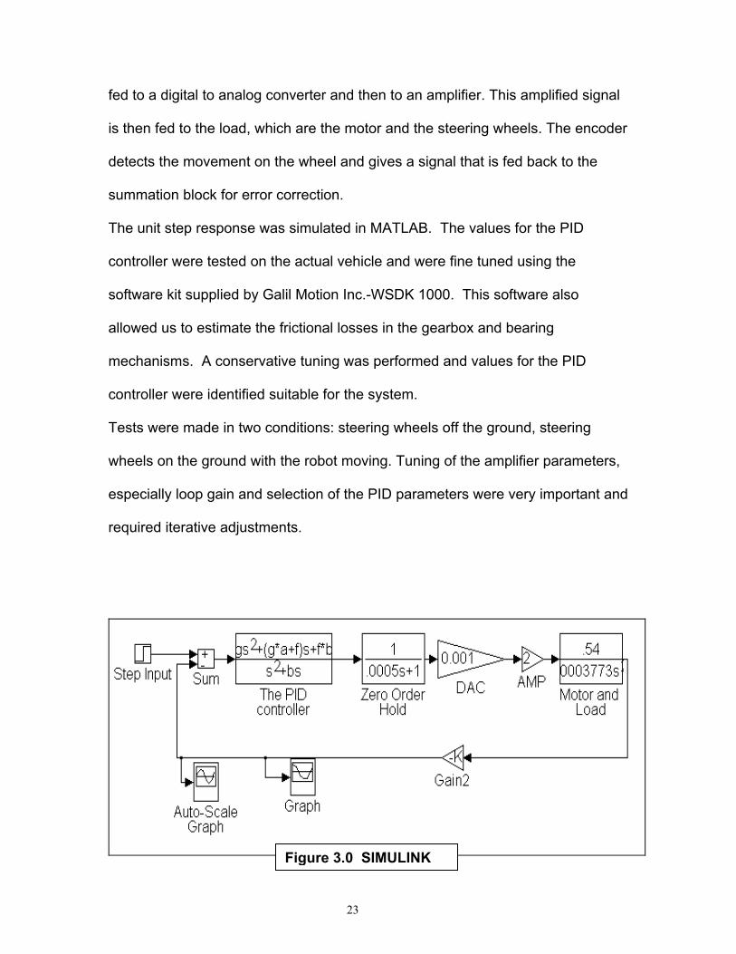
fed to a digital to analog converter and then to an amplifier. This amplified signal
is then fed to the load, which are the motor and the steering wheels. The encoder
detects the movement on the wheel and gives a signal that is fed back to the
summation block for error correction.
The unit step response was simulated in MATLAB. The values for the PID
controller were tested on the actual vehicle and were fine tuned using the
software kit supplied by Galil Motion Inc.-WSDK 1000. This software also
allowed us to estimate the frictional losses in the gearbox and bearing
mechanisms. A conservative tuning was performed and values for the PID
controller were identified suitable for the system.
Tests were made in two conditions: steering wheels off the ground, steering
wheels on the ground with the robot moving. Tuning of the amplifier parameters,
especially loop gain and selection of the PID parameters were very important and
required iterative adjustments.
Figure 3.0 SIMULINK
23
The interface for the system was implemented using a Galil 1030-motion control
computer interface board. A Galil breakout board permits the amplifier and
encoded to be easily connected. The steering mechanism gets its input for the
angle to be moved from three inputs: the distance from the obstacle to be
avoided and the angle of the line and distance from the robot centroid from the
vision algorithm. Feedback is provided at a low level by a position encoder and
at a high level by the vision and sonar systems.
1.7 Safety and Emergency Stop System
The safety and emergency stop system consists of remote controlled emergency
stops, manually operated emergency stops, and the braking system. The mobile
robot must be activated by a remote unit from a distance of no less than 50 feet
in compliance with the rules for this contest. The remote controlled emergency
stop consists of a transmitter, a receiver, an amplifier and a relay, which is
designed to operate from at least 65 feet.
The Futaba transmitter uses a 6V DC and transmits FM signals at 72.470 MHz
over a range of more than 50 feet. These signals are received and converted
into a current that is amplified with a gain factor of 120. This amplified current
24
activates the contacts of the relay that activate the brake and cuts power to the
motor.
The manual emergency stop unit consists of three manual push buttons situated
on easily accessible side surfaces of the robot. When pushed, the power to the
motors are cut off and the self-locking mechanism of the gearbox brings the robot
to an instant halt. This serves as a safety measure against any possible runaway
situation for the robot.
To prevent short-circuits between the aluminum frame and the power units, we
insulated the whole range of power systems; the batteries, connections and
switches. Three levels of insulation and protection were given to ensure
maximum safety and reliability. The monitors have been shielded to prevent their
interference with the Remote E-Stop.
All the components were rigidly tightened to the base, proper cleating was done
and the hard disk was shock mounted to tolerate shocks and vibrations. All the
circuits are color coded to ensure proper re-connection, in case they need to be
removed. To prevent the destruction of any component, the design has been
consciously chiseled such that the aluminum frame forms the boundary on all
sides and only the frame will come in contact if there is a crash.
25

1.8 Fault Diagnostic System
The Bearcat II robot consists of mechanical, electrical, electronic and optical
systems. Ensuring the reliability of such a machine, which is still in the prototype
stage, is a difficult task. Since this robot has been built from scratch at the
University, it does not have any trouble shooting manuals. Nor does the robot
have any self-diagnostic measures (as in the case of commercial industrial
robots). Presently, fault diagnosis and repair is done manually relying solely on
the expertise of the team members. All along it has been a common experience
that rapid fault fixing is perhaps the key to ensuring the required performance of
the robot at the contest.
With these considerations in mind a computer aided Robot Fault Diagnostic
System (RFDS) was developed. Using a top-bottom approach the robot is sub-
divided into different functional units. These are analyzed in depth in terms of
potential failures and their effects on the robot as a whole. The possible causes
of failures and their corresponding remedies were explored through the
technique of Potential Failure Modes and Effects Analysis (PFMEA).
26
1.9 High Level Control Logic
The high-level control scheme is based on a fuzzy logic, hierarchical control
system. The vision system continually updates the steering angle. Whenever
the ultrasound detects an obstacle, it provides information to the controller to let
the robot turn away from the obstacle. When the obstacle is avoided the robot
resumes the original line following algorithm.
The advantages of the fuzzy logic system are that multiple types of input such as
that from vision and sonar sensors as well as stored map information can be
used to guide the robot. Sensor fusion can be accomplished between real time
sensed information and stored information in a manner similar to a human
decision-maker. Vision guidance is accomplished with a CCD camera with a
zoom lens. The data is collected through a commercial tracking device,
communicating to the computer the X, Y coordinates of a lane marker.
Testing of these systems yielded positive results by showing that at five miles per
hour, the vehicle can follow a line and avoid obstacles. The obstacle detection
uses information from Polaroid sonar detection system. The motor control system
uses a programmable Galil motion control system. This design, in its modularity,
creates a portable autonomous controller that could be used for any mobile
vehicle with only minor adaptations.
27
Chapter 2
ELEMENTS OF THE EXPERT SYSTEM
The expert system obtains the specification requirements for the robot - the input
from the user - using simple English. An inference engine converts the text
answers into engineering parameters. These parameters are then used to
develop various design constraints and selection factors, which are used to
select the appropriate components from its corresponding manufacturer or
supplier’s catalog. Thus, the expert system can be broadly broken down into the
following elements:
2.1 User interface
The user interface is the feature that effects knowledge acquisition for the expert
system by facilitating the user to influence the design flow. Visual Basic 6.0 (VB)
was chosen to develop the interface because of the simplicity with which various
forms could be created and the compatibility of VB with Windows NT and web.
28
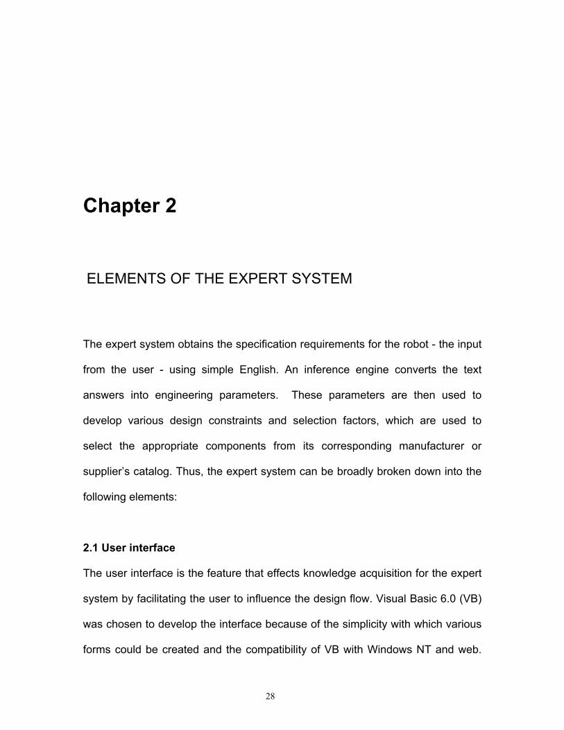
VB Forms create a comfortable environment to the user with online help, context-
based help, facilitating ease of navigation and operation. The interface for stand
alone version is shown below.
These forms were used to put forth seemingly non-technical English questions,
and the results were converted to technical parameters using heuristic
approximations. These technical parameters were used in the design
calculations to select components for the robot.
Figure 4.0 Screen shot of the Expert System
One of the most important aims of an expert system is to keep the user interface
simple, elegant and professional. The Microsoft’s interface layout was chosen as
most decision-makers of the today’s industry are familiar with the same.
29
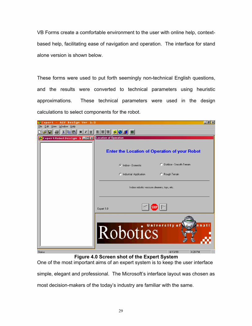
The interface developed has primarily two main windows. They are explained
below: Figure 5.0 Detailed Screen shot of the Expert System
Agent that talks to the user
The main design window, where the
design calculations, user choices and inferences are recorded for the user to view and save.
This is the main user interface that receives data from the user, based on which the robot is designed
Standard text edition control tool bar and menu
The design button that begins a new design
The in built browser The support document
Navigational buttons that take the user from one step to another or back or exit.
30

2.2 Knowledge base:
The knowledge base is the main repository for domain-specific heuristics23.
These are the design logic, various domain facts, inter-relationships,
approximations, already evolved algorithms and ideas that could be used to
support the flow of the design. Our experience and the design documentation of
Bearcat I, Bearcat II, and Dr. Ernie Hall were the main contributor for this
knowledge base.
2.3 Database / catalog collection
This is a collection of manufacturers’ product catalogs, for every component of
the robot. These include the product numbers, specification, design parameters
to be known, selection procedure, product drawings, approximate price, vendor
name, number and address.
About 93 different components were used in the robot and the number of
components within the scope of the paper was about 70. Data was collected and
compiled for an array of every product type, in all possible variations made by the
manufacturer. These were used as master databases, to choose the right
component from the design parameter in hand.
2.4 Inference engine
This is the main computation engine that controls the flow of design based on the
algorithm in the knowledge base and the input from the user through the user
31
interface, making assumptions, selecting the components, verifying the
assumptions and making inferences from the data in hand. This is an inherent
part of the control code and this regulates the design sequence. The inference
engine studies the individual rules, exceptions, inter-relationships and guides the
code accordingly to select the right component in the database.
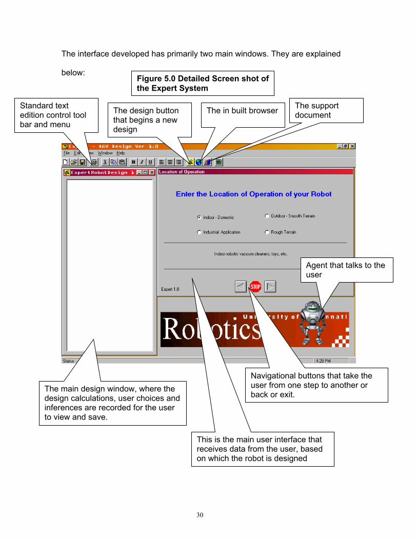
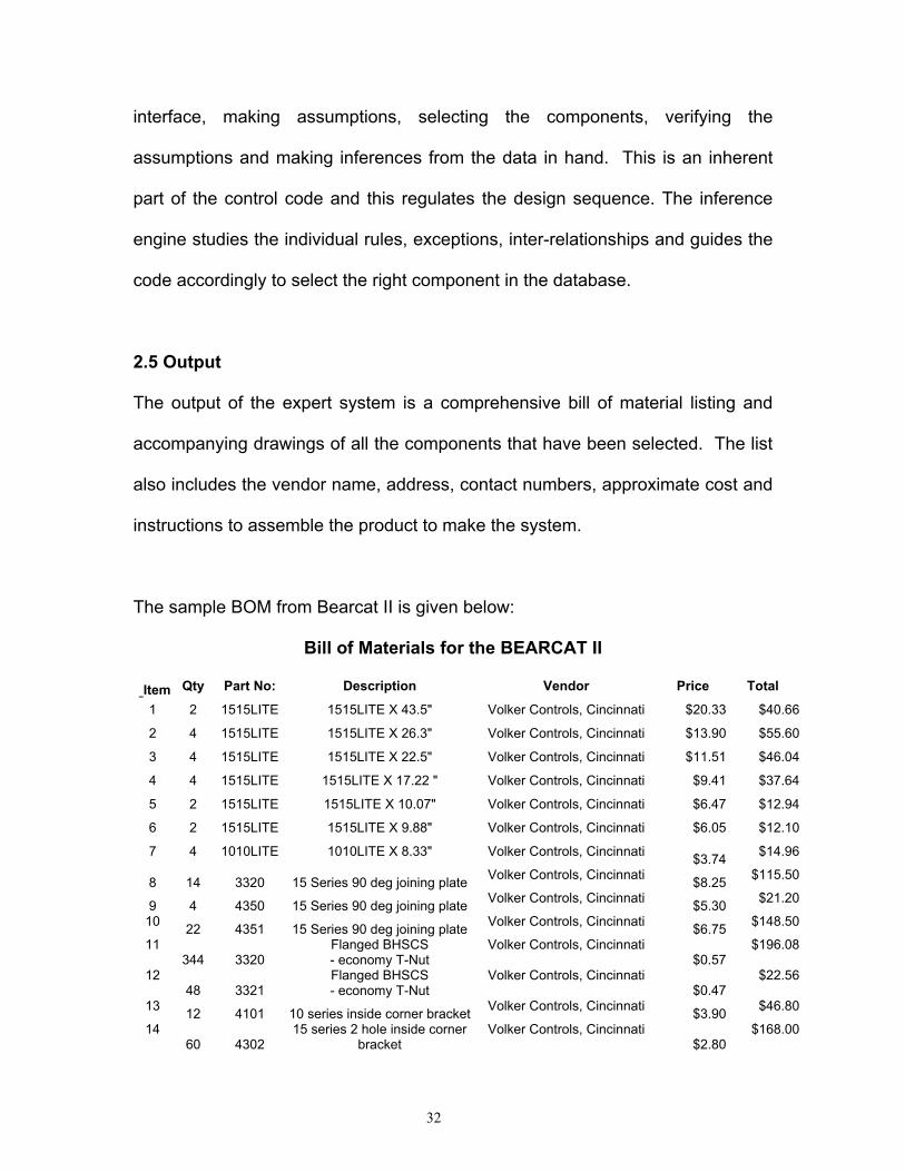
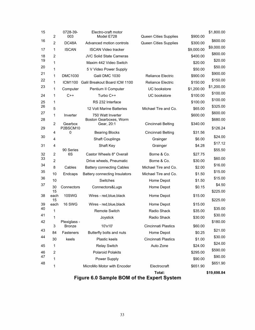
2.5 Output
The output of the expert system is a comprehensive bill of material listing and
accompanying drawings of all the components that have been selected. The list
also includes the vendor name, address, contact numbers, approximate cost and
instructions to assemble the product to make the system.
The sample BOM from Bearcat II is given below:
Bill of Materials for the BEARCAT II
Item Qty Part No: Description Vendor Price Total
1 2 1515LITE 1515LITE X 43.5" Volker Controls, Cincinnati $20.33 $40.66
2 4 1515LITE 1515LITE X 26.3" Volker Controls, Cincinnati $13.90 $55.60
3 4 1515LITE 1515LITE X 22.5" Volker Controls, Cincinnati $11.51 $46.04
4 4 1515LITE 1515LITE X 17.22 " Volker Controls, Cincinnati $9.41 $37.64
5 2 1515LITE 1515LITE X 10.07" Volker Controls, Cincinnati $6.47 $12.94
6 2 1515LITE 1515LITE X 9.88" Volker Controls, Cincinnati $6.05 $12.10
7 4 1010LITE 1010LITE X 8.33" Volker Controls, Cincinnati $3.74 $14.96
8 14 3320 15 Series 90 deg joining plate Volker Controls, Cincinnati $8.25 $115.50
9 4 4350 15 Series 90 deg joining plate Volker Controls, Cincinnati $5.30 $21.20
10 22 4351 15 Series 90 deg joining plate Volker Controls, Cincinnati $6.75 $148.50
11 344 3320
Flanged BHSCS - economy T-Nut
Volker Controls, Cincinnati $0.57
$196.08
12 48 3321
Flanged BHSCS - economy T-Nut
Volker Controls, Cincinnati $0.47
$22.56
13 12 4101 10 series inside corner bracket Volker Controls, Cincinnati $3.90 $46.80
14 60 4302
15 series 2 hole inside corner bracket
Volker Controls, Cincinnati $2.80
$168.00
32
15 2
0728-39-003
Electro-craft motor Model E728 Queen Cities Supplies $900.00
$1,800.00
16 2 DC48A Advanced motion controls Queen Cities Supplies $300.00 $600.00
17 1 ISCAN ISCAN Video tracker $9,000.00 $9,000.00
18 2 JVC Solid State Cameras $400.00 $800.00
19 1 Maxim 442 Video Switch $20.00 $20.00
20 1 5 V Video Power Supply $50.00 $50.00
21 1 DMC1030 Galil DMC 1030 Reliance Electric $900.00 $900.00
22 1 ICM1100 Galil Breakout Board ICM 1100 Reliance Electric $150.00 $150.00
23 1 Computer Pentium II Computer UC bookstore $1,200.00 $1,200.00
24 1 C++ Turbo C++ UC bookstore $100.00 $100.00
25 1 RS 232 Interface $100.00 $100.00
26 5 12 Volt Marine Batteries Michael Tire and Co. $65.00 $325.00
27 1 Inverter 750 Watt Inverter $600.00 $600.00
28 2 Gearbox
Boston Gearboxes, Worm Gear, 20:1 Cincinnati Belting $340.00
$680.00
29 4
P2BSCM100 Bearing Blocks Cincinnati Belting $31.56
$126.24
30 4 Shaft Couplings Grainger $6.00 $24.00
31 4 Shaft Key Grainger $4.28 $17.12
32 2 90 Series
6S Castor Wheels 8" Overall Borne & Co. $27.75$55.50
33 2 Drive wheels, Pneumatic Borne & Co. $30.00 $60.00
34 8 Cables Battery connecting Cables Michael Tire and Co. $2.00 $16.00
35 10 Endcaps Battery connecting Insulators Michael Tire and Co. $1.50 $15.00
36 10 Switches Home Depot $1.50 $15.00
37 30 Connectors Connectors&Lugs Home Depot $0.15 $4.50
38 15
each 10SWG Wires - red,blue,black Home Depot $15.00$225.00
39 15
each 16 SWG Wires - red,blue,black Home Depot $15.00$225.00
40 1 Remote Switch Radio Shack $35.00 $35.00
41 1 Joystick Radio Shack $30.00 $30.00
42 3
Plexiglass - Bronze 10'x10' Cincinnati Plastics $60.00
$180.00
43 84 Fasteners Butterfly bolts and nuts Home Depot $0.25 $21.00
44 30 keels Plastic keels Cincinnati Plastics $1.00 $30.00
45 1 Relay Switch Auto Zone $24.00 $24.00
46 2 Polaroid Polakits $295.00 $590.00
47 1 Power Supply $90.00 $90.00
48 1 MicroMo Motor with Encoder Electrocraft $651.90
$651.90
Total: $19,698.84Figure 6.0 Sample BOM of the Expert System
33

Chapter 3
STRUCTURE OF THE PROBLEM
3.1 Problem decomposition
An autonomous mobile robot is a sophisticated multi-input, multi-output intelligent
system. Figure 6 shows the block diagram of the entire system. The major
components of this AGV are: Vision guidance system, Speed and steering
control system, Obstacle avoidance system, Safety and braking system, Power
unit, and the Supervisor control PC. Following is a description on the design and
development of the main subsystems of the mobile robot.
The design of a complex mechanical system like an automated guided vehicle
must be done by hierarchical decomposition of the design problem into simpler
units and continue this breakdown until the units reach individual component
levels. These components then can be easily designed, integrated to form major
sub-units and then, on further integration, would lead to the whole system.
34

Figure 7.0 Block diagram of the Robot Components
35

The main difficulty in this decomposition approach is properly identifying the unit
groups and isolating them. One logical approach is to define the boundaries of
Design steps
Identification of critical components of each sub-unit
Determination of design parameters to select each t
Summarization of the causal parameters by design t i t
Identification of the individual sub-units
Input parameters, which depend on User’s choice
Search for the component from the manufacturers’ t l
Add to the Bill of materials and go to the next t
Step 1
Step 2
Step 3
Step 4
Step 5
Step 6
Step 7
Transmission, power,.. t
Power battery, inverter, t
Battery volts., current t
12 V battery 12 V M t
Payload, color etc..
Give the final list/Drawings Step 8 Bill of materials
Examples
Product Selection Algorithm
Figure 8.0 Product Selection Logic
36

the units in such a way that they would have minimal causal effect on other units.
That is, the demarcation needs to be done in such a way that the dependency of
the parameters of one unit with other units should be minimal.
Our vehicle can broadly be decomposed into the following major sub-systems:
• The Robot Base
• The Vision System
• The Sonar System
• The Motion Control System
• The Control Logic
• The Safety and Braking System
Of these, the scope of this paper restricts itself to the algorithm to develop the
base, the power units and the transmission of the robot. The components that fall
within the scope of the paper can be further simplified into major sub-units.
3.2 Sub-classification to component level: These major units can be
simplified into component level units that can be designed with the help of
standard design procedures and can be selected from the corresponding
manufacturers’ catalog.
For example: The transmission unit can be simplified as:
motor to gearbox coupling
motor to gearbox coupling key
gearbox
gearbox base
37

gearbox base bolts and nuts
gearbox to Wheel shaft coupling
gearbox to wheel shaft coupling key
wheel shaft
wheel - wheel shaft key
wheel shaft supporting bearing blocks
wheel shaft supporting bearing blocks bolts.
gearbox-bearing block spacers
bearing-block wheel spacers.
wheel bolts.
Thus, a comprehensive list of components can be made and the design or
selection of each material can be done depending on the specification.
3.3 Identification of design parameters: The next most important step is to
identify the parameters that need to be known to select these components.
These parameters can be classified as two types:
1. Causal parameters
2. Specification parameters
Causal parameters: These are the parameters of a component, which directly
depend on a parameter of another component either within the unit, or in the sub-
system or the system as a whole. The main idea of the approach is to identify all
38

the casual parameters and make the most of this dependency. The aim is to
achieve the design of the robot with minimal questioning of the user.
Example of causally dependent parameter:
At the unit level:
The inner dia. (i.d.) of the wheel = outer dia. (o.d.) of the shaft = i.d. of the
bearings = i.d. of the spacers = i.d. of one end of gearbox shaft coupling.
At the sub-system level:
The o.d. of the motor shaft = i.d. of the gearbox-motor coupling top end.
At the system level:
The weight of all the components + payload = load on the motor.
Specification parameter: These are the user-input parameters. They can be
further classified into two groups viz., functional specifications and non-functional
specification. For example: The color of the robot skin is a non-functional
specification and the required speed of the robot is a functional specification
parameter.
The user, through the VB interface, feeds these parameters into the system logic.
3.4 Product selection: Once all the required parameters are determined, either
by questioning the user or through causal relationships, the corresponding
manufacturer’s database is searched on the primary specification needs and the
39
matching product is selected. If no such product is found, the iterations are
repeated with a different set of assumptions.
Once the product is selected, the factors initially assumed on the product are
verified and, if they do not match, the assumptions are changed in the
subsequent direction and the design is repeated. However, this time, the user is
not prompted for data input and the existing data set ID is re-used. However, a
counter is incremented each time the design is iterated due to wrong
assumptions, and if the counter reaches 40, the user is prompted to enter a
different set of data, prompting him that the given data is unusable.
3.5 Bill of material generation: This selection procedure is repeated for all the
components, and when done, a comprehensive bill of material list is generated.
Supporting drawings, supplier details, cost, assembly suggestions are also
generated.
40
Chapter 4
Why Visual Basic? The user interface is the feature that effects knowledge acquisition for the expert
system by facilitating the user to influence the design flow. Visual Basic 6.0 (VB)
was chosen to develop the interface because of the simplicity with which various
forms could be created and the compatibility of VB with Windows NT. VB Forms
create a comfortable environment to the user with online help, context-based
help, facilitating ease of navigation and operation.
These forms were used to put forth seemingly non-technical English questions,
and the results were converted to technical parameters using heuristic
approximations. These technical parameters were used in the design
calculations to select components for the robot.
Visual Basic is derived from the Basic language, which is a structured
programming language. However, Visual Basic uses an event-driven
programming model.
41
4.1.1 Procedural Applications In traditional or procedural applications, the application controls which portions of
code run and the sequence in which they run. Application execution starts with
the first line of code and follows a predefined path through the application, calling
procedures as needed.
4.1.2 Event-Driven Applications In an event-driven application, execution does not follow a predetermined path.
Instead, different code sections run in response to events. Events can be
triggered by the user's actions, by messages from the system or other
applications, or from inside the application itself. The sequence of events
determines the sequence in which the code runs. Therefore, the path through the
application's code can differ each time the program runs.
An essential part of event-driven programming is writing code that responds to all
the possible events that may occur in an application. Visual Basic makes it easy
to implement an event-driven programming model.
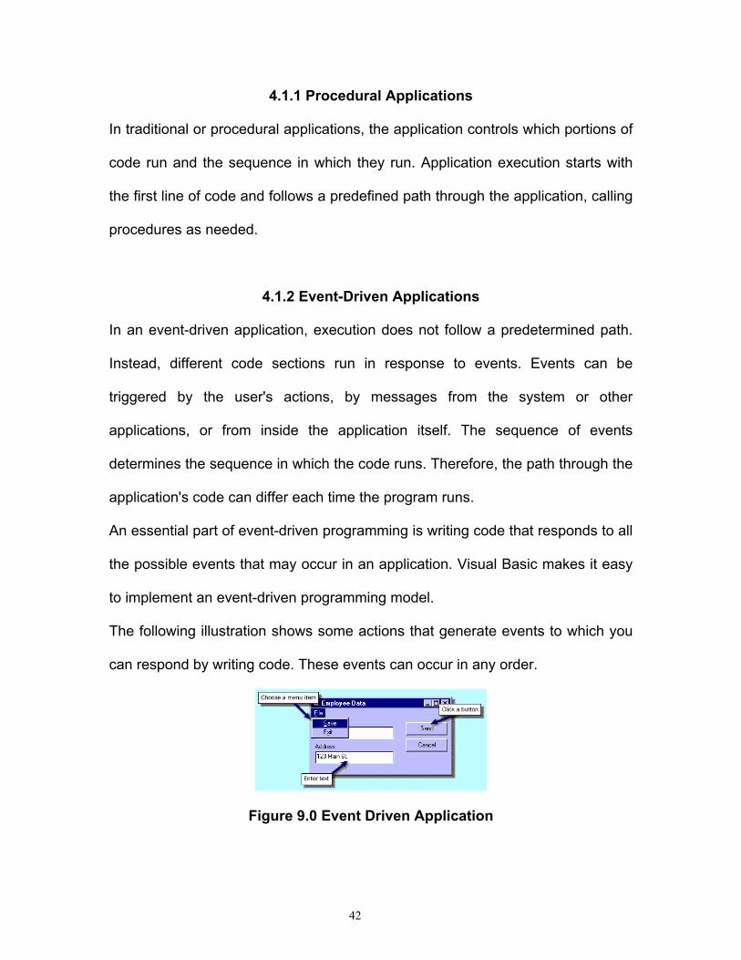
The following illustration shows some actions that generate events to which you
can respond by writing code. These events can occur in any order.
Figure 9.0 Event Driven Application
42
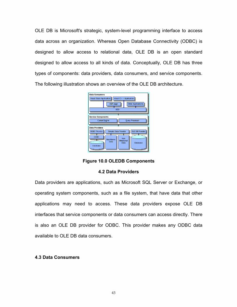
OLE DB is Microsoft's strategic, system-level programming interface to access
data across an organization. Whereas Open Database Connectivity (ODBC) is
designed to allow access to relational data, OLE DB is an open standard
designed to allow access to all kinds of data. Conceptually, OLE DB has three
types of components: data providers, data consumers, and service components.
The following illustration shows an overview of the OLE DB architecture.
Figure 10.0 OLEDB Components
4.2 Data Providers Data providers are applications, such as Microsoft SQL Server or Exchange, or
operating system components, such as a file system, that have data that other
applications may need to access. These data providers expose OLE DB
interfaces that service components or data consumers can access directly. There
is also an OLE DB provider for ODBC. This provider makes any ODBC data
available to OLE DB data consumers.
4.3 Data Consumers
43

Data consumers are applications that use the data exposed by data providers.
ADO is the programmatic interface for using OLE DB data. Any application that
uses ADO is an OLE DB data consumer.
4.4 Service Components Service components are components of OLE DB that process and transport data.
These components include query processors and cursor engines. Architecturally,
OLE DB is separated into components so data providers do not need to have the
innate ability to provide data in a way that ADO can understand. These service
components give ADO the ability to consume OLE DB data from providers that
don't inherently offer handling of result sets or interpretation of SQL queries.
For more information about Universal Data Access and OLE DB, see Microsoft
Strategy for Universal Data Access in the Library.
Although applications that use Data Access Objects (DAO) and Remote Data
Objects (RDO) will run correctly in Visual Basic 6, ADO is the data-access
method Microsoft recommends for new applications.
Advantages of Using ADO
ADO is an evolution of the RDO and DAO architectures. ADO combines the best
features of RDO and DAO, and replaces them with one robust, easy-to-use
interface. RDO and DAO limited you to using ODBC and Jet compliant data
providers. ADO, however, provides quick, high-performance access to all of the
44

types of data and information that are available through OLE DB, while
maintaining a low overhead in terms of memory and disk space.
4.5 ADO Overview For simple applications, you can use the Data Environment designer to add ADO
objects to your project at design time. This technique requires little or no code to
interact with a data source. In more sophisticated applications, you can add code
to work with ADO objects and their properties, methods, and events.
When you work with ADO programmatically, you typically use the following three
ADO objects:
Connection
An ADO Connection object is used to create a connection to a data source.
Command
An ADO Command object is used to return data from a connection. Command
objects can also manipulate data in a data source or call a SQL Server stored
procedure.
45

Recordset
An ADO Recordset object is used to store the result set of a query on the data
source.
4.6 OLE DB Data Providers Applications using ADO consume OLE DB data by using the appropriate data
provider. For example, you use the OLE DB provider for SQL Server to access
data in a SQL Server database. Because there is an OLE DB provider for ODBC,
you can write ADO code to access data in your existing ODBC data sources that
do not have a native OLE DB provider.
COM components are self-contained units of code that provide specific
functionality. Using COM, you can build several different components that work
together as a single application. Separating your code into components gives you
the ability to develop and test small, encapsulated pieces of your application
independently. It also enables multiple developers to work on a project together
by allowing tasks to be distributed among the members of the development team.
Designing your applications using COM components also enables you to use
multiple instances of an object within your application. The following illustration
shows how you can create an Employee component, and then, at run time, you
can create two instances of that component.
46

Figure 11.0 Employee Illustration
COM components can be either internal components, which are compiled into a
project and are available only to that project, or external components, which are
compiled into executable files or dynamic-link libraries. External components can
be used by any client application that supports COM. You use COM components
in exactly the same way, regardless of whether they are internal or external
components.
4.7 Advantages
There are many reasons to use COM components in an application:
Reusability
Once you create a COM component, other developers can use it. This enables
easy access to your component's features in other applications without requiring
developers to write extensive code. A developer can use the Object Browser to
get information about the properties, methods, and events exposed by your COM
component. For more information, see Using the Object Browser in this chapter.
47

Reduced complexity
You can create a COM component to hide programming complexity from other
programmers. Other programmers need only know what information to provide to
your component, and what information to retrieve.
Easier updating
Components make it easier for you to revise and update your applications. For
example, you can create a COM component that encapsulates business rules. If
the business rules change, you update just the component, and not all the
applications that use the component.
Windows Distributed internet Applications Architecture (Windows DNA) is a
development framework for building scalable, distributed applications based on
the Windows platform. With Windows DNA, application developers can build and
extend solutions that combine the most desirable aspects of personal computer
applications, client/server applications, and Internet applications.
You can build these integrated applications and components by writing COM
components and by accessing the Windows application services exposed
through Microsoft Transaction Server and other enabling technologies.
The following illustration shows the general structure of Windows DNA.
48
Chapter 5
ABSTRACT ALGORITHM OF THE DESIGN
The seed of the logic was based on our development of an AGV for the
“Automated Unmanned Vehicle System competition, 1998”. The robot was made
as an industrial robotic kit with the buy-only ideas behind it, as the time we had to
complete the robot was very limited. The design calculations were encoded in
Mathcad 6.0, so that many iterations could be done with different data sets as
per our requirement. The logic used and the design process was then analyzed
and encoded into a computer system. The abstract logic is given below.
5.1. Initialize the assumption variables
5.2. Get the area of operation - µ - The co-efficient of friction between the
surface of operation and the type of wheel to be used
49

5.3. Get the speedmax. – This is the maximum speed at which the vehicle
should move. Usually not more than 10mph
5.4. Get the payload – The maximum load the robot may be carrying other
than its’ self-weight.
5.5. Get the hours required to move around without recharging. This is useful
to determine the capacity of the battery.
5.6. Ask the user…whether he needs 12v or 6v battery (If the user does not
know use 12v). Estimate the weight of the batteries.
5.7. Ask him how many cameras he may use. Default = 2. Estimate the weight
of the cameras.
5.8. How many monitors the user needs? Estimate the weight of the monitors.
5.9. How many sonars the user needs?
5.10. Is the user going to use a laptop/palmtop/desktop? This converts itself to
the corresponding load on the machine
5.11. What is the factor of safety to use? Use 150% as default.
5.12. Calculate total mass = known mass + payload * factor of safety. (Assume
no. of batteries). Use the steel cage to be 200 lbs.
5.13. Thus the total mass of the robot is estimated by
5.14. M items M battot M cbat M cpu M iscan M montot M motortot M inv M camtot M misc M gearboxtot M couplingtot M frame M shaftot
5.15. M M items M castortot M bblocktot M wheeltot
5.16. Ask the user the type of the wheel to use
5.17. Ask for clearance (ground clearance)
5.18. The wheel dia. cannot exceed dia. 12-24 inches dia.
50

5.19. Ask the user whether to use rubber wheels/iron wheels/plastic?
5.20. Ask the user, the application environment and decide the width of the
robot.
5.21. Select wheel from the catalog for the specification and to carry half the
load.
5.22. Check weight assumptions – check the selected wheel.
5.23. Get r2, r3 – the inner diameters of the rim and the wheel
5.24. Calculate in revolutions/minute the speedmax, for the dia. of the wheel
from
5.25. N rS vS 1 and
S 1 ..2 πD o2 where, D.o is the dia. and S.v is the speedmax.
5.26. get jrim J rim
...π ρ 1 h 1 R 14 R 3
4
( ).2 g Where, ρ.1, h.1 and R.1 and R.2 are
the density, width and radii at the rim and jrim is the inertia of the rim
5.27. Similarly, J web
...π ρ 1 h 2 R 34
.2 g . Where, jweb is the inertia of the web
5.28. And J tire
...π ρ 1 h 2 R 24 R 1
4
.2 g . Where jtire is the inertia of the tire
5.29. J total J rim J web J tire
5.30. Find force to overcome self-weight – use the static friction co-efficient.
F f ..µ M g
5.31. Find the torque T friction .F f R 2
5.32. Ask for acceleration required? Convert this to the corresponding angular
acceleration needed
51
5.33. α..a 2 π
S 1 Where a is the acceleration
5.34. Determine the inertial torque reflected through the gear train to the motor
side
5.35. J inertiaatmotor .J total1i
2
Where, i floor
N motorN r
1 and floor = lower round off
of the argument.
5.36. Determine gear ratio, i
5.37. Check for worm and wheel specifications and check weight assumptions
5.38. Determine torque to overcome static frictional force. Where, Tftom =
frictional torque of motor
T total ..J motor J transmission .J inertiaatmotora α 2 T frictionthrugear T ftom
5.39. Total torque the motor needs to overcome.
5.40. Find in the motor manufacturer catalog - choose motor
5.41. Choose corresponding amplifier (12V),
5.42. Check assumption regarding the weight of the motor
5.43. Ask can he use an inverter?
5.44. If yes...choose an inverter. From 12V or 6V DC to motor input voltage from
the catalog. Check weight assumptions.
5.45. Find total power required, choose battery from catalog based on the
specifications
5.46. Find number of batteries required.
5.47. Check if the selected parameters match with the assumptions
52

5.48. Design bearing block to hold shearing load on the eyes of the base, axial
and radial load on the inner race.
5.49. Make use of all causal parameters and select the bearing blocks. Check
assumptions
5.50. Design the two types of couplings on shear, crushing and compressive
strengths. And check assumptions
5.51. Check the shaft on the basis shear, crushing and compressive loads and
check the assumptions.
5.52. Ask the number of castors to be used Use 1 as default.
5.53. Ask whether the user wants castor wheel rubber or iron?
5.54. From ground clearance, choose castors...check assumptions
5.55. Calculate component lengths.
5.56. Add a factor and find the lengths of the 80-20 components. Use the logic
of the 80-20 library.
5.57. Add fastener, ends, joiners etc., Check the load assumptions.
5.58. Choose I-scan for high speed image tracking.
5.59. Ask for parameters to choose sonars and select sonar kits.
5.60. Select Galil motion controller.
5.61. Ask for appearance requirements of the user.
5.62. Choose plexi-glass.
5.63. Give the list.
53

Chapter 6
RESULTS
After an extensive testing of the code in the module level, the program was
integrated to develop the product. Sample data was fed in, simulating the
requirement of a user for an industrial robot.
1. The expert system gave out a comprehensive list of “Bill of Material” (BOM)
along with the manufacturer’s details and contact numbers.
2. The robot was fed with tested data, like that of Bearcat. The program output
the list with 91% accuracy. About 73 different components were listed in the
BOM.
3. Modifications and extensions in the code were made to make the logic more
rugged to variations and during the testing of the same, the code was broken
into modules and each module output was found to match the expectations.
4. The constructed Bearcat is shown in Figure 12.0
54
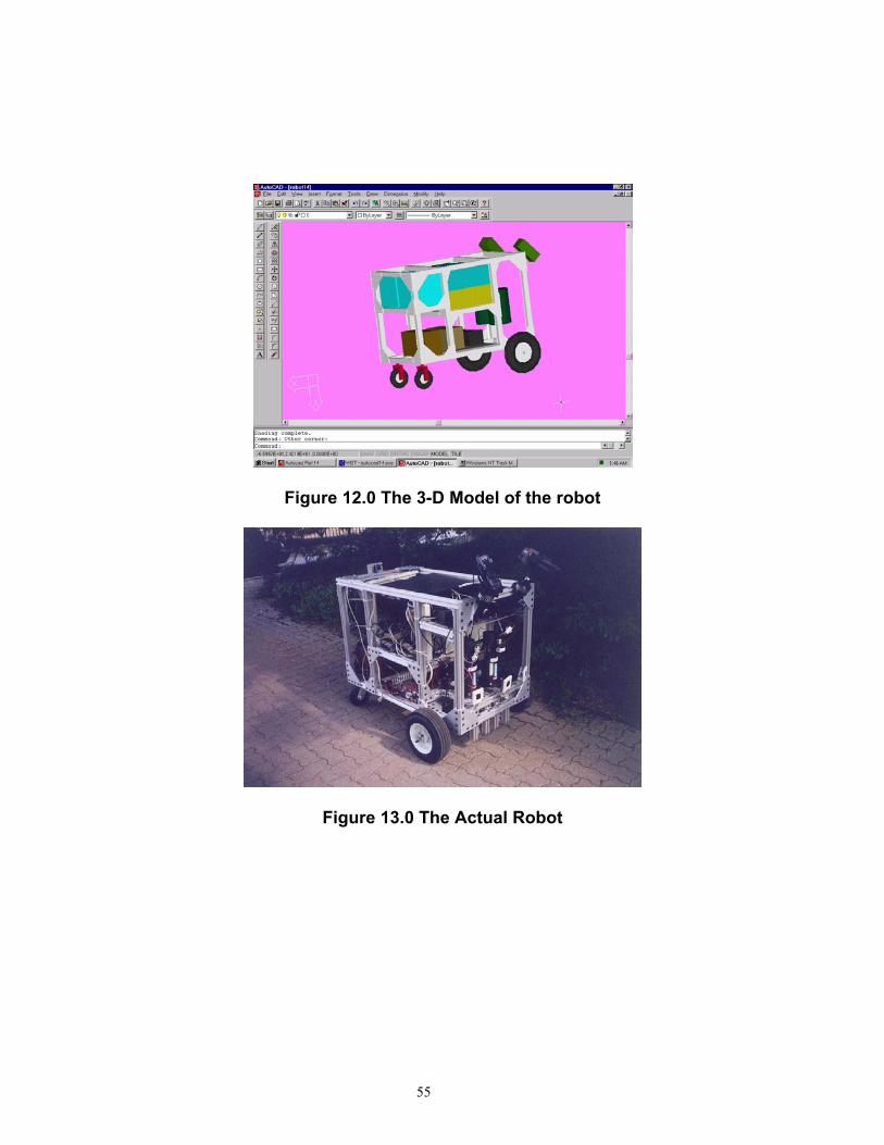
Figure 12.0 The 3-D Model of the robot
Figure 13.0 The Actual Robot
55
Chapter 7
CONCLUSION AND RECOMMENDATIONS
An expert system to design the base of a robotic vehicle similar to Bearcat II has
been designed. The software should be useful to the decision-makers and
managers, to perceive the robot and analyze the automation before investing in
it.
The comprehensive bill of materials with approximate costs and the supplier
addresses could be also useful for making investment decisions. Thus, the
robot-making technology can be brought down from R & D rooms to the shop-
floor management.
Some of the enhancements that could be made in this program are to make it
more versatile in order to handle all types of land robots, like tracked vehicles or
pneumatically levitated vehicles. A parametric modeler interface could be
developed to effect real-time variations on the screen.
56
The experience in developing this software was an excellent learning experience
and it is the first step aimed towards bridging the gap between R&D and shop
floor.
57
Appendix 1 /*********************************************************************** File name: Camera.c */ // Authors: Karthikeyan Kumaraguru and Sameer Parasnis #include "camera.h" void camera_change( int change ){ #define RIGHT 1 #define LEFT 2 if ( change == RIGHT ) submitDMC("CB2"); if ( change == LEFT ) submitDMC("SB2"); }#include "g-cart.h" // Header file used with this code. #include "rotatson.h" #include "galil.c" #include "setpid.c" // Sets the PID values #include "tsonar.c" #include "galil.c" #include "camera.c" #include "vision.c" #include "vis_main.c" // Vision auto mode #include "car.c" // Starts, stops, steers and speedens the robot #include "test_cam.c" // To test the cameras #include "man_move.c" // To manually move the robots #include "vis_demo.c" // To test the vision # include "rotatson.c" #include "ftl.c" //follow the leader time_t first = time (NULL); void Escape_to_exit(void); void Escape_to_exit(void) { cout << "\tPress <<Enter>> to continue, <<Esc>> to exit>>"; Switchit: switch (getch()) {
58

case 13: break; case 27: exit(0); break; default: goto Switchit; } } void main() { clrscr(); kartcount = 0; cout << "\t\t\tThe Bearcat II control software"; cout << "\n\n\n\nSTEP 1: Reset Galil "; Escape_to_exit(); initDMC(); //Initializing DMC(galil.c) cout << "\nSTEP 2: Reset I-scan "; cout << "\n Verify LOT light "; Escape_to_exit(); initISCAN(); //Initializing Iscan(Iscan.c) cout << "\nSTEP 3: Reset Sonars, Verify firing sound"; cout << "\nSTEP 4: Check amplifier lights and E-STOP"; cout << "\nSTEP 5: Check monitors "; Escape_to_exit(); cout << "\n\n"; initsonarmotor(); //rotatson.c setpid(); //setpid.c Show_status: cout << "\n\n\nIf you don't have some of the above components" << " connected, you would have got a lot of errors. " << " If everything was ok, you would have got " << " some 'command received' outputs. If you ignore " << " the errors, a few of the options may not work.\n\n\t"; Escape_to_exit(); Showmenu: char getkeyvalue; while(1) //Menu loop begins { clrscr(); gotoxy(0,0); cout <<"\n\t\t\t BEARCAT II Main Menu \n\n" <<"\t\t\t <1> Test Sonar \n" <<"\t\t\t <2> Test Vision \n" <<"\t\t\t <3> Test Camera Switch \n" <<"\t\t\t <4> Test Motors/Galil\n" <<"\t\t\t <5> Move cart Manually\n" <<"\t\t\t <6> Run Cart-Auto Mode\n\n" <<"\t\t\t <7> Quit Program \n\n" <<"\t\t\t <8> Follow The Leader \n\n" <<"\t\t\t <0> Kill Motors\n\n" <<"\t\t\t Enter desired OPTION: ";
59

getkeyvalue=getch(); switch (getkeyvalue) { case '1': cout << "\n\nIf sonar is not connected..\n" << "your computer is going to hang"; Escape_to_exit(); rotatson(); break; //rotatson.c case '2': vis_demo(); break; // case '3': test_camera(); break; case '4': submitDMC("JG 10000, "); //Run the motors submitDMC("JG ,10000"); submitDMC("SH"); submitDMC("BG"); break; case '5': manual_move(); break; //man_mov.c case '6': vis_main(); break; //vis_main.c case '8': ftlmain(); break; //launch Fallow the Leader case '7': case 27: stopCAR(); //stops and exits exit(0); break; //Escape key case '0': stopCAR(); break; }; // End of Switch statement }; // End of While(menu) loop } // End of main() function /*********************************************************************** #include "iscan.h" // Authors: Tayib Samu, Kalyan Kolli, Karthikeyan Kumaraguru and Sameer Parasnis void initISCAN() { outp(IO1_Base+3, 0x93); outp(IO2_Base+3, 0x8a); } int Input_Raw_Target_Data(int param) { int New_Data; int holder; // Set Up Compad0 & Compad 1 for Parameter holder = inp(IO2_Base+2); holder &= 0xF9; holder |= param; outp(IO2_Base+2, holder); // Strobe Data Request Line outp(IO1_Base+2,0x10); sleep(1); outp(IO1_Base+2,0x00); sleep(1); outp(IO1_Base+2,0x10); // Capture Data
60

sleep(1); New_Data = inp(IO1_Base) + ((inp(IO1_Base+2) & 0x01) << 8); return(New_Data); }; void setgate(wind *tmp) { int datum[4]; int holder,bit8; datum[0]=tmp->pos_x; datum[1]=tmp->pos_y; datum[2]=tmp->siz_x; datum[3]=tmp->siz_y; for(int code=0;code<4;code++) { bit8=0; if(datum[code]&256) { bit8=1; datum[code]=datum[code]-256; } holder=inp(IO2_Base+2); holder=holder & 0xF9 ; holder=holder | (2*code); outp(IO2_Base+2,holder); holder=inp(IO2_Base+2); holder=holder & 0xFE; holder=holder | bit8; outp(IO2_Base+2,holder); outp(IO2_Base,datum[code]); holder=inp(IO2_Base+2); holder=holder & 0xF7; holder=holder|8; outp(IO2_Base+2,holder); sleep(6); holder=holder&0xf7; outp(IO2_Base+2,holder); sleep(6); holder=holder|8; outp(IO2_Base+2,holder); } } /****************************************************************************** // Authors: Tayib Samu, Kalyan Kolli, Karthikeyan Kumaraguru and Sameer Parasnis #include "vis_l.h" #include "wintest1.c" #include "tstson.h" int vis_l(void){
61
#define DELAY1 10 #define DELAY2 10 #define SONAR FALSE int count = 0; float obsdist; int y1_size_c=0; int y2_size_c=0; int x1_size_c=0; int x2_size_c=0; int vis_count = 0; int cor3,cor4,cor3P,cor4P; int currentcenter =60; int reactiondistance =24; // Calibrtation values struct constant2 { float a11; float a12; float a13; float a14,a21,a22,a23,a24; }; constant2 *con; con = new constant2; float angle =0; float z_coord= 22.25; //The calibration coefficients as calculated on June 05 1999 con->a11= -7.625; con->a12= 1.8333; con->a13= -5.0833; con->a14= 576.2448; con->a21= 0.25; con->a22= -8.3333; con->a23= -5.16667; con->a24= 175.8021; float angleC, SonANGLE, angleD, angle1, angle2; initISCAN(); //initialiaze iscan startCAR(); //spdx = 7000; speedCARx(base_speed); //spdy = 7000; speedCARy(base_speed); CAMERA = 2; wind *win1= new wind; wind *win2= new wind;
62

coordinate *crd1=new coordinate; coordinate *crd2=new coordinate; coordinate *crd3=new coordinate; coordinate *crd4=new coordinate; //define window 1 x,y pos win1->pos_x=255; win1->pos_y=100; //define window 2 x,y pos win2->pos_x=255; win2->pos_y=200; //define windows size win1->siz_x=win2->siz_x=500; win1->siz_y=win2->siz_y=10; float angle_emer=0.0; float old_angle=0.0; clrscr(); while(!kbhit()){ kartcount ++; gotoxy(10,1); cout << "\t LEFT CAMERA (" << CAMERA << ") ****> Loop counter = " << kartcount << "\n\n"; setgate(win1); getdata(crd1); gotoxy(1,3); cout << "First image co-ordinate: " << "crd1->LOT: " << crd1->LOT; gotoxy(1,4); cout << "Co-ordinate 1 (X,Y) = (" << crd1->pos_x << "," << crd1->pos_y << ")"; gotoxy(1,5); cout << "Co-ordinate 1 size (X,Y) = (" << crd1->siz_x << "," << crd1->siz_y << ")"; if (crd1->LOT != 2) return(1); setgate(win2); sleep(DELAY1); getdata(crd2); gotoxy(40,3); cout << "Second image co-ordinate: " << "crd2->LOT: " << crd2->LOT; gotoxy(40,4); cout << "Co-ordinate 2 (X,Y) = (" << crd2->pos_x << "," << crd2->pos_y << ")"; gotoxy(40,5); cout << "Co-ordinate 2 size (X,Y) = (" << crd2->siz_x << "," << crd2->siz_y << ")"; gotoxy(1,5); if (crd2->LOT != 2) return(1); //Calculating the real world co-ordinates crd3,crd4 from image // co-ordinates crd1,crd2...respectively float det=(con->a22*con->a11)-(con->a21*con->a12); crd3->pos_x=((con->a22*(crd1->pos_x-con->a14-(con->a13*(-z_coord)))) - ((crd1->pos_y-con->a24-(con->a23*(-z_coord)))*con->a12))/det;
63

crd4->pos_x=((con->a22*(crd2->pos_x-con->a14-(con->a13*(-z_coord)))) - ((crd2->pos_y-con->a24-(con->a23*(-z_coord)))*con->a12))/det; crd3->pos_y=((con->a11*(crd1->pos_y - con->a24 - (con->a23*(-z_coord)))) - (crd1->pos_x - con->a14 - (con->a13*(-z_coord)))*con->a21)/det; crd4->pos_y=((con->a11*(crd2->pos_y-con->a24-(con->a23*(-z_coord)))) - ((crd2->pos_x-con->a14-(con->a13*(-z_coord)))*con->a21))/det; /* cout<<"The first world X-coordinate is"<<crd3->pos_x<<endl; cout<<"The first world Y-coordinate is"<<crd3->pos_y<<endl; cout<<"The second world X-coordinate is"<<crd4->pos_x<<endl; cout<<"The second world Y-coordinate is"<<crd4->pos_y<<endl; */ float A=crd3->pos_x - crd4->pos_x; float B=crd3->pos_y - crd4->pos_y; float angle =(atan(A/B))*180.0/3.14; float actual_angle = angle; float angleC; float dist= ((crd3->pos_x + crd4->pos_x)/2.0); // Softening the angle to minimize stray data // angle = (angle+old_angle)/2; gotoxy(20,7); cout << "Calculated angle of line = " << angle; /* compute distance error */ float d_error = 60.0-dist; normalsweep(); /*******************************************************************/ /* Here begins the logic - tested */ // These fewlines actuate sensor data fusion, replacing fuzzy logic /*******************************************************************/ if (dist == currentcenter) { angleC = (angle)+(OBSPRESENT*OBSSIDE*15); } if (dist > currentcenter) { angleC = (atan(reactiondistance/(currentcenter-dist))*(180.0/3.14)+angle+90)+(OBSPRESENT*OBSSIDE*15); gotoxy(20,14); cout << "Distance is greater than currentcenter! Dist: " << dist; gotoxy(20,15); cout << "atan(): "<< angleC-90-angle << "+ 90 + " << angle << " = " << angleC; } if (kbhit() ) exit(0); if (dist < currentcenter)
64
{ angleC = (-90+atan(reactiondistance/(currentcenter-dist))*(180.0/3.141)+angle)+(OBSPRESENT*OBSSIDE*15); gotoxy(20,14); cout << "Distance is less than currentcenter! Dist: " << dist; gotoxy(20,15); cout << "90 - atan(): "<<angleC-angle <<"+angle"<< angle << " = " << angleC; } /******************************************************/ /*Here ends the logic that replaces the fuzzy approach*/ /******************************************************/ // if ( angleC >= 30.0) angleC = 30.0; // if ( angleC <= -30.0) angleC = -30.0; gotoxy(20,8); cout <<"Corrected angle of line = "<<angleC; cout<<"\n\n\t\tDistance: "<<dist<<"\t Dist_err: "<<d_error<<"\n"; old_angle = angle; if (kbhit()) { stopCAR(); exit(0); } steerCAR(angleC); } //return 5; stopCAR(); } //end of main /************************************************************************* Filename: car.c Last modified: 5-28-98 // Authors: Kalyan Kolli, Karthikeyan Kumaraguru and Sameer Parasnis *************************************************************************/ #include "car.h" #ifndef CAR #define CAR extern time_t first; void speedCARx(long int spx) { //This command when invoked will set the speed of bearcat II. //It is called with a value between 0 - 250000. char inx[10],sendx[15]; gcvt(spx,6,inx); char *commandx="JG"; strcpy(sendx,commandx); strcat(sendx,inx); gotoxy(10,21); cout<< " Left-motor: "; gotoxy(24,21);
65

cout << sendx; gotoxy(1,23); cout << "X-motor --> "; //if(!TEST) submitDMC(sendx); submitDMC("BGX"); } void speedCARy(long int spy){ //This command when invoked will set the speed of bearcat II. //It is called with a value between 0 - 250000. char iny[10],sendy[15]; gcvt(spy,6,iny); char *commandy="JG,"; strcpy(sendy,commandy); strcat(sendy,iny); gotoxy(38,21); cout<<"Right-Motor: "; gotoxy(52,21); cout << sendy; gotoxy(1,24); cout<< "Y-motor --> "; //if(!TEST) submitDMC(sendy); submitDMC("BGY"); } void positionsonar(int posz) { char inz[10],sendz[15]; gcvt(posz,6,inz); char *commandz="PA,,"; strcpy(sendz,commandz); strcat(sendz,inz); gotoxy(55,20); cout<<"Sonar: "; gotoxy(62,20); cout << sonarposindex; submitDMC(sendz); submitDMC("BGZ"); sleep(2000); } void stopCAR(){ gotoxy(1,23); submitDMC("ST"); submitDMC("ST"); submitDMC("MO"); submitDMC("MO"); submitDMC("SH"); gotoxy(1,23); cout << "\t\t\t\t\t\t\t\t\t\t\t\t\t Stopped Running\t\t\t\t\t\t\t\t\t\t\t\t\t"; }
66
void steerCAR(float val) { double dtime; time_t second=time(NULL); gotoxy (25,12); cout << " "; gotoxy(20,16); cout << "Inside steercar: -->VAL: " << val << "\n"; //This function when invoked will put the steering wheel to the absolute //angle given. This angle ranges between +-20. dtime=difftime(second,first); cout << "Time data: first = "<< first << " second = "<< second; cout << " dtime = " << dtime << endl; first=second; dtime = 0.25; //temprory code begins.....Karthik 05/26/99*/ /* if (val <= -30) { spdx = 10000; spdy = 4000; } if (val >= 30) { spdx = 4000; spdy = 10000; }*/ if (val < 5 && val > -5) { spdx = base_speed; spdy = base_speed; } else /*if (val >= 5 && val <= 30 || val <= -5 && val>=-30)*/ { spdx=base_speed-((134.5*val)/1); spdy=base_speed+((134.5*val)/1); } if (spdx > 36000)spdx =36000; if (spdx < -36000)spdx =-36000; if (spdy > 36000)spdy =36000; if (spdy < -36000)spdy =-36000; cout << "\t\tspdx = " << spdx << " "; cout << "spdy = " << spdy << " "; cout << "increment = " << (int)((134.5*val)/dtime) << " "; speedCARx(spdx); speedCARy(spdy); } void auto_steerCAR(float val) { //This function when invoked will put the steering wheel to the absolute
67

//angle given. This angle ranges between +-20. char inc[10],send[15]; //slow car int spdx=-.05*abs(val)+COMP_SPEED; speedCARx(spdx); //steer car steerCAR(val); } void startCAR() { //This function when called will initialize the galil board. initDMC(); set_upDMC(); // for(int wait= 0;wait<500;wait++); // download("c:\galil\speed.dcp"); // submitDMC("XQ"); } void steerCARleader(float val,float refspeed) { double dtime; time_t second=time(NULL); gotoxy (25,12); cout << " "; gotoxy(20,16); cout << "Inside steercar: -->VAL: " << val << "\n"; //This function when invoked will put the steering wheel to the absolute //angle given. This angle ranges between +-20. dtime=difftime(second,first); cout << "Time data: first = "<< first << " second = "<< second; cout << " dtime = " << dtime << endl; first=second; dtime = 0.25; if (val < 2 && val > -2) { spdx = base_speed; spdy = base_speed; } else /*if (val >= 5 && val <= 30 || val <= -5 && val>=-30)*/ { spdx=refspeed-((134.5*val)/1); spdy=refspeed+((134.5*val)/1); } cout << "\t\tspdx = " << spdx << " ";
68

cout << "spdy = " << spdy << " "; cout << "increment = " << (int)((134.5*val)/dtime) << " "; speedCARx(spdx); speedCARy(spdy); } // ***************************************************************************** // Authors: Karthikeyan Kumaraguru and Sameer Parasnis #endif// man_move.c #include "man_move.h" int manual_move() { clrscr(); char c; spdx = 0; spdy = 0; startCAR(); gotoxy(10,7); cout<< " ************************************************************"; gotoxy(6,9); cout << "Use the folowing:\n\n" << "\t7 F-LEFT\t\t8 INCREASE\t\tF-RIGHT 9\n" << "\t4 ZTR-L \t\t5 STOP CAR\t\t ZTR-R 6 \n" << "\t1 B-LEFT\t\t2 DECREASE\t\tB-RIGHT 3\n" << "\t\t\t\t0 TO QUIT\n"; while(c!='0'){ gotoxy(15,16); c = getch(); gotoxy(15,17); cout << "\t Action: "; switch (c) { case '8': gotoxy (35,17); cout<<"Increase Speed\n\t"; if(spdx+spdy==0) { spdx=ZERO_SPEED; spdy=ZERO_SPEED; speedCARx(spdx); speedCARy(spdy); } else if(spdx>spdy) spdx=spdy; else if(spdx<spdy) spdy=spdx;
69
else if((spdx>=MAX_SPEED)||(spdy>=MAX_SPEED)) { spdx=MAX_SPEED-SPEED_INC; spdy=MAX_SPEED-SPEED_INC; gotoxy (35,17); cout<<"Maximum Speed \n\t"; } spdx+=SPEED_INC; spdy+=SPEED_INC; speedCARx(spdx); speedCARy(spdy); break; case '2': gotoxy (35,17); cout<<"Decrease Speed\n\t"; if(spdx+spdy==0) { spdx=ZERO_SPEED; spdy=ZERO_SPEED; } else if((spdx<=MIN_SPEED)||(spdy<=MIN_SPEED)) { spdx=MIN_SPEED; spdy=MIN_SPEED; gotoxy (35,17); cout<<"Minimum Reversed\n\t"; break; } else if(spdx<spdy) spdx=spdy; else if(spdx>spdy) spdy=spdx; spdx-=SPEED_INC; spdy-=SPEED_INC; speedCARx(spdx); speedCARy(spdy); break; case '5': gotoxy (35,17); cout << "Stopping Car \n\t"; spdx=ZERO_SPEED; spdy=ZERO_SPEED; angle=0; stopCAR(); break; case '4': gotoxy (35,17);
70
cout << "ZTR Left Side \n\t"; if(spdx+spdy==0) { spdx-=STEER_INC; spdy+=STEER_INC; speedCARx(spdx); speedCARy(spdy); } else { gotoxy (35,17); cout << "Stopping Car \n\t"; spdx= -1*STEER_INC; spdy= 1*STEER_INC; speedCARx(spdx); speedCARy(spdy); } break; case '6': gotoxy (35,17); cout << "ZTR Right Side\n\t"; if(spdx+spdy==0) { spdx+=STEER_INC; spdy-=STEER_INC; speedCARx(spdx); speedCARy(spdy); } else { spdx= 1*STEER_INC; spdy= -1*STEER_INC; speedCARx(spdx); speedCARy(spdy); } break; case '7': gotoxy (35,17); cout << "Forward Left \n\t"; spdx-=STEER_INC; speedCARx(spdx); break; case '9': gotoxy (35,17); cout << "Forward Right \n\t"; spdy-=STEER_INC; speedCARy(spdy); break; case '1': gotoxy (35,17); cout << "Backward Left \n\t"; spdx+=STEER_INC; speedCARx(spdx);
71
break; case '3': gotoxy (35,17); cout << "Backward Right\n\t"; spdy+=STEER_INC; speedCARy(spdy); break; default: break; }; // End switch(c) }; // do until '0' is entered gotoxy (35,17); cout<<"clearing PC\n\t"; stopCAR(); clearPC(); return(0); }; // End of manual_move() // ***************************************************************************** // Authors: Karthikeyan Kumaraguru and Sameer Parasnis #include "visloo.c" #include "sonloo.c" #include "vis_r.c" #include "vis_l.c" void vis_main() { #define Right 1 #define Left 2 int LOT =0; initISCAN(); //initialiaze iscan startCAR(); speedCARx(2000); speedCARy(2000); while(!kbhit()) { // goto changetoleft; changetoright: CAMERA=1; camera_change(Right); if (kbhit() == 27) exit(0); LOT = 1; while(LOT != 0) { LOT = LOT + vis_r(); if (CAMERA!=1) goto changetoleft; if (LOT >= 5)
72

{ clrscr(); cout << "LOT encountered. Press a key to continue.."; sleep(2000); // getch(); goto changetoleft; // LOT = 0; } // goto END; } changetoleft: if (kbhit() == 27) exit(0); CAMERA = -1; camera_change(Left); LOT = 1; while(1) { LOT = LOT + vis_l(); if(CAMERA!=-1) goto changetoleft; if (LOT >= 5) { clrscr(); cout << "LOT encountered. Press a key to continue.."; sleep(2000); // getch(); goto changetoright; // LOT = 0; } } }//While loop ends END: stopCAR(); //car.c }// Main ends // serial.c // Authors Kalyan Kolli, Krishnamohan Kola, Cao Jin and Peter #include "serial.h" /* open serial port using ROM BIOS routine */ char * readString(char * str){ //str = (char *)malloc(sizeof(char *)*256); int i=0; while((str[i]!=10)&&(i<256)){ // if(in_ready()){ i++; str[i]=get_serial(); } // } if(str[i]==10){ str[i] = NULL; for(int count = 0;count<i;count++){ str[count]= str[count+1];} if(SONAR_DEBUG) cout<<"\ndata"<<str<<"DATA";
73

return str; } else cout<<"bad exit"; exit(0); return(0); } /* while(i<256){ if(in_ready()){ i++; str[i] = get_serial(); cout<<"char: "<<str[i]<<" for i:"<<i<<"\n"; if(str[i]==10){ str[i]=NULL; //str++; for(int count=0;count<i;count++) str[count]=str[count+1]; cout<<"\ndata"<<str<<"DATA"; return str; } } } return NULL; } */ void open_port() { union REGS regs; /* load AH with the function code */ regs.h.ah =0x00; /* load AL with the baud rate and 8-N-1 */ regs.h.al = 0xe3; /* load DX with the port number */ regs.x.dx = 1; /* call the ROM BIOS routine */ int86(0x14, ®s, ®s); } /* put character to the serial port */ void put_serial(int c) { union REGS regs; /* load AH with the function code */ regs.h.ah = 0x01;
74
/* load AL with the character */ regs.h.al = c; /* load DX with the port numbrt */ regs.x.dx = 1; /* call the ROM BIOS routine */ int86(0x14, ®s, ®s); } /* get character from the serial port */ int get_serial() { union REGS regs; /* load AH with the function code */ regs.h.ah = 0x02; /* load DX with the port number */ regs.x.dx = 1; /* call the ROM BIOS routine */ int86(0x14, ®s, ®s); /* return EOF if timed out */ if (regs.h.ah & 0x80) return EOF; return regs.h.al; } /* check to see if a character is ready */ int in_ready() { union REGS regs; /* load AH with the function code */ regs.h.ah = 0x03; /* load DX with the port number */ regs.x.dx = 1; /* call the ROM BIOS routine */ int86(0x14, ®s, ®s); /* check for received data ready */ if (regs.h.ah & 1) return TRUE; return FALSE; } //This program was developed by Sameer and Karthik Date: 06/01/99 //This program rotates the sonar motor fromleft to right.
75
//The sonar was tested at 24khz and reliability was achieved for //at obstacle diatnce 100 inches. Obstacles were place at an arc of 100 //inches at the center of the robot and at 1.5 feet away from the robot // The angles with repect to the robot was found to be -24,0,24 degrees //With an encoder count of 2048/rev, this translates to -140,0,140 counts //The sonar will stop at -140,-70,0,70,140 counts int positionz; int rotatson() { positionz = 0; initsonarmotor(); testloop: normalsweep(); //test code begins if(kbhit()) { if (getch() == 27) { submitDMC("PA,,0"); exit(0); } } else goto testloop; //testcodeends } int maxstop; //This is the maximum number of stops of the sonar initsonarmotor() { maxstop = 2; submitDMC("SH"); submitDMC("AC,,350000"); submitDMC("SP,,350000"); submitDMC("DP,,0"); submitDMC("DP,,0"); } float normalsweep() { float obsdistance; positionz = sonarposindex*140-140; positionsonar(positionz); gotoxy(1,1); //cout << " "; gotoxy (1,1); obsdistance = snl();
76
cout << "distance = " << obsdistance << " position = " << sonarposindex; if (sonarposindex == maxstop) sonarposindex = 0; else sonarposindex++; //OBSSIDE = 1 if obstacle is in the right //OBSSIDE = 2 if obstacle is in the center //OBSSIDE = -1 if obstacle is in the left // if OBSPRESENT = 0, there is no obstacle // if obspresent =1, there is an obstacle being sensed. if (obsdistance <= 95) { OBSPRESENT = 1; if (sonarposindex != maxstop/2) OBSSIDE = (maxstop/2-sonarposindex)/abs(maxstop/2-sonarposindex); else OBSSIDE = 2; } else { OBSPRESENT = 0; } return (obsdistance); } int oldposition; float rotatetotheta(int theta) { int positioncount, leaderdist; if (theta >= 0) positioncount = - oldposition + theta*(512/90); else positioncount = -(theta*(512/90) - oldposition); positionsonar(positioncount); leaderdist= snl(); return leaderdist; } // ***************************************************************************** // Authors: Karthikeyan Kumaraguru and Sameer Parasnis #include "vis_r.h" #include "tstson.h" int vis_r(void){ #define DELAY1 10 #define DELAY2 10 #define SONAR FALSE int count = 0; int y1_size_c=0; int y2_size_c=0; int x1_size_c=0;
77
int x2_size_c=0; int vis_count = 0; int cor3,cor4,cor3P,cor4P; int currentcenter=60; int reactiondistance=24; // Calibration values struct constant2 { float a11; float a12; float a13; float a14,a21,a22,a23,a24; }; constant2 *con; con = new constant2; float angle =0; float z_coord= 20.00; //The values are as calibrated on June 05 1999 con->a11= 7.2500; con->a12= -2.00; con->a13= 6.5; con->a14= 33.4063; con->a21= 0.3333; con->a22= -8.333; con->a23= -2.000; con->a24= 315.3333; float angleC, SonANGLE, angleD, angle1, angle2; initISCAN(); //initialiaze iscan startCAR(); //spdx = 7000; speedCARx(base_speed); //spdy = 7000; speedCARy(base_speed); wind *win1= new wind; wind *win2= new wind; coordinate *crd1=new coordinate; coordinate *crd2=new coordinate; coordinate *crd3=new coordinate; coordinate *crd4=new coordinate; //define window 1 x,y pos win1->pos_x=255; win1->pos_y=100;
78

//define window 2 x,y pos win2->pos_x=255; win2->pos_y=200; //define windows size win1->siz_x=win2->siz_x=500; win1->siz_y=win2->siz_y=10; float angle_emer=0.0; float old_angle=0.0; clrscr(); while(!kbhit()){ kartcount ++; gotoxy(10,1); cout << "\t RIGHT CAMERA (" << CAMERA << ") ****> Loop counter = " << kartcount << "\n\n"; setgate(win1); getdata(crd1); gotoxy(1,3); cout << "First image co-ordinate: " << "crd1->LOT: " << crd1->LOT; gotoxy(1,4); cout << "Co-ordinate 1 (X,Y) = (" << crd1->pos_x << "," << crd1->pos_y << ")"; gotoxy(1,5); cout << "Co-ordinate 1 size (X,Y) = (" << crd1->siz_x << "," << crd1->siz_y << ")"; if (crd1->LOT != 2) return(1); setgate(win2); sleep(DELAY1); getdata(crd2); gotoxy(40,3); cout << "Second image co-ordinate: " << "crd2->LOT: " << crd2->LOT; gotoxy(40,4); cout << "Co-ordinate 2 (X,Y) = (" << crd2->pos_x << "," << crd2->pos_y << ")"; gotoxy(40,5); cout << "Co-ordinate 2 size (X,Y) = (" << crd2->siz_x << "," << crd2->siz_y << ")"; gotoxy(1,5); if (crd2->LOT != 2) return(1); //Calculating the real world co-ordinates crd3,crd4 from image // co-ordinates crd1,crd2...respectively float det=(con->a22*con->a11)-(con->a21*con->a12); crd3->pos_x=((con->a22*(crd1->pos_x-con->a14-(con->a13*(-z_coord)))) - ((crd1->pos_y-con->a24-(con->a23*(-z_coord)))*con->a12))/det; crd4->pos_x=((con->a22*(crd2->pos_x-con->a14-(con->a13*(-z_coord)))) - ((crd2->pos_y-con->a24-(con->a23*(-z_coord)))*con->a12))/det; crd3->pos_y=((con->a11*(crd1->pos_y - con->a24 - (con->a23*(-z_coord)))) - (crd1->pos_x - con->a14 - (con->a13*(-z_coord)))*con->a21)/det; crd4->pos_y=((con->a11*(crd2->pos_y-con->a24-(con->a23*(-z_coord)))) - ((crd2->pos_x-con->a14-(con->a13*(-z_coord)))*con->a21))/det;
79

float A=crd3->pos_x - crd4->pos_x; float B=crd4->pos_y - crd3->pos_y; /* gotoxy(1,1); // cout<<"The first world X-coordinate is"<<crd3->pos_x<<endl; cout<<"The first world Y-coordinate is"<<crd3->pos_y<<endl; cout<<"The second world X-coordinate is"<<crd4->pos_x<<endl; cout<<"The second world Y-coordinate is"<<crd4->pos_y<<endl; cout<<"\n\n\nA="<<A<<endl; cout<<"B="<<B<<endl; cout << "A/B" << A/B << endl; cout << "atan(0) =" << atan(A/B) << endl; */ float angle =atan(A/B)*180/3.1416; //cout << "atan(DEGREE) = " << angle << endl; // if (angle < 0) angle = (0-(90+angle)); float actual_angle = angle; float angleC; float dist= (crd3->pos_x + crd4->pos_x)/2.0; // Softening the angle to minimize stray data // angle = (angle+old_angle)/2; gotoxy(20,7); cout << "Calculated angle of line = " << angle; /* compute distance error */ float d_error = 60.0-dist; normalsweep(); /*******************************************************************/ /* Here begins the logic - to be tested */ // These fewlines actuate sensor data fusion, replacing fuzzy logic /********************************************************************/ if (dist == currentcenter) { angleC = (angle)+(OBSPRESENT*OBSSIDE*15); } if (dist > currentcenter) { angleC = (atan(reactiondistance/fabs(currentcenter-dist))*180.0/3.14)+angle-90+(OBSPRESENT*OBSSIDE*15); gotoxy(20,11); cout << "Distance is greater than currentcenter! Dist: " << dist; //gotoxy(20,12); //cout << " "; gotoxy(20,12); cout << "atan(): "<< angleC-90-angle << "+ 90 + " << angle << " = " << angleC; } if (dist < currentcenter) { gotoxy(20,11);
80

cout << "Distance is less than currentcenter! Dist: " << dist; angleC = (90.0-atan(reactiondistance/fabs(currentcenter-dist))*(180.0/3.141)+angle)+(OBSPRESENT*OBSSIDE*15); //gotoxy(20,12); //cout << " "; gotoxy(20,12); cout << "90 - atan(): "<<angleC-angle <<" + "<< angle << " = " << angleC; } /******************************************************/ /*Here ends the logic that replaces the fuzzy approach*/ /******************************************************/ // if ( angleC >= 30.0) angleC = 30.0; // if ( angleC <= -30.0) angleC = -30.0; gotoxy(20,8); cout <<"Corrected angle of line = "<<angleC; cout<<"\n\n\t\tDistance: "<<dist<<"\t Dist_err: "<<d_error<<"\n"; old_angle = angle; if (kbhit()) { stopCAR(); exit(0); } steerCAR(angleC); } //return 5; stopCAR(); } //end of main float sonloo(float rowval, float colval) { float row_int1,row_int2,col_int; int i,j,carryon=1,min_row,max_row,min_col,max_col; float temp,answer; // FILE *fp; // static float a[20][20]; static int m=11,n=10,count=0; // static float a[8][12]; float b[11][10] = {{0,-36,-25,-18,-10,0,10,18,25,36}, {66,-36,-25,-20,-12,-4,6,14,21,32}, {50,-36,-25,-22,-16,-10,0,8,15,26}, {35,-36,-30,-25,-20,-18,-8,-0,8,18}, {15,-36,-36,-30,-30,-22,-10,-2,3,14}, {1,-36,-36,-36,-36,-36,-26,-18,-11,0}, {-1,0,11,18,26,36,36,36,36,36}, {-15,-14,-3,2,10,22,30,30,36,36}, {-35,-18,-8,0,8,18,20,25,30,36}, {-50,-26,-15,-8,0,10,16,22,25,36}, {-66,-32,-21,-14,-6,4,12,20,25,36}};
81

// We now sort the matrix in ascending order for rows and columns // Sorting the columns in ascending order first carryon=1; while(carryon) { carryon=0; for(j=1;j<n-1;j++) //Moving along the column in the first row { if(b[0][j] > b[0][j+1]) // Comparing the elements to interchange { // Loop to interchange the elements of two columns through all rows carryon=1; for(i=0;i<m;i++) { temp=b[i][j]; b[i][j]=b[i][j+1]; b[i][j+1]=temp; } } } } // Now sorting the rows carryon=1; while(carryon) { carryon=0; for(i=1;i<(m-1);i++) { if(b[i][0] > b[i+1][0]) //interchange if this is true { for(j=0;j<n;j++) { temp=b[i][j]; b[i][j]=b[i+1][j]; b[i+1][j]=temp; } carryon=1; } } } // The matrix has been sorted throughout and is printed below /* for(i=0;i<m;i++) { for(j=0;j<n;j++) printf("%6.2f\t",b[i][j]); printf("\n"); } */ // The matrix has been printed // count++; //} // For the if loop, does this only the first time function is called //***************************************************************** // The following code is executed everytime the function is called // First locate the rows between which the given value lies // If the row value is out of bounds, print a warning and extrapolate for(i=2;i<m;i++) {
82

if((rowval<=b[i][0])&&(rowval>b[i-1][0])) { min_row=i-1; max_row=i; //Locating the two bounds of row indexes break; } // If the row value is out of bounds, print a warning and extrapolate if(rowval>=b[m-1][0]) { // printf("lookup WARNING: Extrapolating, Row index value more than bounds\n"); min_row=m-2;max_row=m-1; // If the row value is higher than table break; } if(rowval<=b[1][0]) { // printf("lookup WARNING: Extrapolating, Row index value less than bounds\n"); min_row=1;max_row=2; // If the row value is lower than table break; } } // Locating the columns in which the value lies for(j=2;j<n;j++) { if((colval<=b[0][j])&&(colval>b[0][j-1])) { min_col=j-1; max_col=j; break; } // If the column value is out of bounds, print a warning and extrapolate if(colval<=b[0][1]) { // printf("lookup WARNING: Extrapolating, column index less than bounds\n"); min_col=1;max_col=2; break; } if(colval>=b[0][n-1]) { // printf("lookup WARNING: Extrapolating, column index more than bounds\n"); min_col=n-2;max_col=n-1; break; } } // We have now located where in the table (grid), the given point lies // Interpolating to get the required values if(b[min_row][min_col]==b[min_row][max_col]) row_int1=b[min_row][min_col]; else row_int1=b[min_row][min_col] + ( ((colval-b[0][min_col])*(b[min_row][max_col]-b[min_row][min_col]) )/(b[0][max_col]-b[0][min_col]) ); // Second row interpolation if(b[max_row][min_col]==b[max_row][max_col]) row_int2=b[max_row][min_col]; else row_int2=b[max_row][min_col] +
83

( ((colval-b[0][min_col])*(b[max_row][max_col]-b[max_row][min_col]))/(b[0][max_col]-b[0][min_col]) ); // Column interpolation if(row_int1 == row_int2) col_int=row_int1; else col_int=row_int1 + ( ((rowval-b[min_row][0])*(row_int2-row_int1))/(b[max_row][0]-b[min_row][0]) ); // Printing the answer and the results on the screen /* printf("Lookup table output: Input number %d is (%6.2f,%6.2f)\n",count,rowval,colval); printf("Grid (coordinates and values) are as follows\n"); printf("NW=(%6.2f,%6.2f) = %6.2f\n",b[min_row][0],b[0][min_col],b[min_row][min_col]); printf("NE=(%6.2f,%6.2f) = %6.2f\n",b[min_row][0],b[0][max_col],b[min_row][max_col]); printf("SE=(%6.2f,%6.2f) = %6.2f\n",b[max_row][0],b[0][max_col],b[max_row][max_col]); printf("SW=(%6.2f,%6.2f) = %6.2f\n",b[max_row][0],b[0][min_col],b[max_row][min_col]); count++; */ // Returning the answer return(col_int); } # include "test_cam.h" // ***************************************************************************** // Authors: Kalyan Kolli, Krishna Mohan Kola and Sameer Parasnis /* Test program to check the switching between cameras... */ void test_camera(void); void camera_change(int); void test_camera(void) { char i=0; //camera_change(RIGHT); cout<<" \n Hit r for switching to Right\n Hit l for the left camera\n"; i=getch(); if( i == 'r'|| i == 'R') camera_change(RIGHT); else if( i == 'L'|| i == 'l') camera_change(LEFT); //camera_change(RIGHT); }//This program will do serveral things //It will obtian the azmuth angle to the //object being followed from the ISCAN //it will then turn towards it and aim //the sonar at it. The sonar will get //a reading which will cause the speed //to increase or decrease. //buffers are built in for very small angles //and very small distance errors // ***************************************************************************** // Authors: Nathan Mundhenk
84
#include "fisheye.c" void Quit_prog(); void ftlmain(); void Quit_prog() // Quit the program entirely { clrscr(); exit(0); } void ftlmain() { int c = 0; float Theta, Speed, ThetaOld, AbsThetaDiff, ThetaDiff, Degree; long int R, DistanceOff, AbsDO, Count; Degree = 10; Speed = 20000; //set speed at 20000 pixles ThetaOld = 0; Count = 0; //startCAR(); //This starts the galil //initDMC(); //initISCAN(); //setpid(); while(1) { cout<<"Starting Follow the Leader\n" <<"Press 1 to stop\n"; c=kbhit(); if (c == 1) { Quit_prog(); } cout <<"Speed " << Speed << "\n\n"; Theta = GetAngle(); //obtain Azmuth Angle +-90 Degrees from fisheye.c if (Count > 0) { ThetaDiff = Theta - ThetaOld; AbsThetaDiff = abs(ThetaDiff); if (AbsThetaDiff < Degree ) //Ignore data that is way off { ThetaOld = Theta; //Theta is kept if its good steerCARleader(Theta,Speed); //Steer car using Car.c cout <<"Angle " << Theta << "\n\n";
85
//rscr(); //SonarAngle = Theta + 90; R = rotatetotheta(Theta); //Turn the sonar Degree = 5; } } else { Degree= Degree + .25 ; //Increase error } Count++; //R = snl(); //Obtain Sonar distance from rotatson.c in inches DistanceOff = 100 - R; //118.11 inches which is 3 meters AbsDO = abs(DistanceOff); if (AbsDO > 4) //Don't change speed if your only off by 4 inches { if (DistanceOff >= 0) //Decrease Speed { Speed = Speed - (DistanceOff *10); } if (DistanceOff < 0) //Increase speed { Speed = -1*((-1*(Speed)) - (DistanceOff *10)); } } } } //setpid as a c file // ***************************************************************************** // Authors: Krishna Mohan Kola, Kalyan Kolli, Sameer Parasnis, Karthikeyan Kumaraguru void setpid(void); void setpid() { submitDMC("DP 0,0,0"); //galil.c submitDMC("SH"); submitDMC("AC 25600"); submitDMC("AC ,25600"); submitDMC("DC 25600"); submitDMC("DC ,25600"); submitDMC("KD 2404.63"); submitDMC("KD ,1826.75"); submitDMC("KD ,,1018.13"); submitDMC("KP 283.50"); submitDMC("KP ,215.30"); submitDMC("KP ,,130.13"); submitDMC("KI 63.13,48.0"); submitDMC("KI ,,34.75");
86
submitDMC("JG 10000,10000"); submitDMC("FL 2147483647"); submitDMC("FL ,2147483647"); submitDMC("BL -2147483648"); submitDMC("BL ,-2147483648"); submitDMC("XQ"); } void vismath(void); void vis_math(){ FILE *debug,*coef; // Calibrtation values struct constant1 { float a11; float a12; float a13; float a14,a21,a22,a23,a24; }; constant1 *con; con = new constant1; float z_coord=23.25; /* struct coordinate{ float pos_x; float pos_y; int siz_x; int siz_y; int LOT; }; */ debug = fopen("Debug.out","w"); coef = fopen("coef.in","r"); fscanf(coef," %f %f %f %f %f %f %f %f",&con->a11,&con->a12,&con->a13,&con->a14,&con->a21,&con->a22,&con->a23,&con->a24); fprintf(debug,"Trial file : for the vision alogorithm \n"); /* con->a11= 14.7; con->a12= -11.5; con->a13= -1.189; con->a14= 415.456; con->a21= -3.567; con->a22= -5.521; con->a23= -9.944; con->a24= 559.417; */ initISCAN(); //initialiaze iscan
87
//startCAR(); wind *win1= new wind; wind *win2= new wind; coordinate *crd1=new coordinate; coordinate *crd2=new coordinate; coordinate *crd3=new coordinate; coordinate *crd4=new coordinate; vision *vis1=new vision; vision *vis2=new vision; //define window 1 x,y pos win1->pos_x=255; win1->pos_y=100; //define window 2 x,y pos win2->pos_x=255; win2->pos_y=200; //define windows size win1->siz_x=win2->siz_x=500; win1->siz_y=win2->siz_y=10; cout<<" \n"; cout<<" Behold the Magic Matrix!:\n"; cout <<"\n"<<"con->a11 = "<< con->a11<<"\n"; cout <<"con->a12 = " << con->a12<<"\n"; cout <<"con->a13 = " << con->a13<<"\n"; cout <<"con->a14 = " << con->a14<<"\n"; cout <<"con->a21 = " << con->a21<<"\n"; cout <<"con->a22 = " << con->a22<<"\n"; cout <<"con->a23 = " << con->a23<<"\n" ; cout <<"con->a24 = " << con->a24<<"\n"; if(TEST) speedCAR(COMP_SPEED); while(!kbhit()){ setgate(win1); sleep(DELAY); getdata(crd1); setgate(win2); sleep(DELAY); getdata(crd2);
88

cout<<"untanted: \n"; cout<<"crd1 x:"<<crd1->pos_x<<"\ty:"<<crd1->pos_y<<"\n"; cout<<"crd2 x:"<<crd2->pos_x<<"\ty:"<<crd2->pos_y<<"\n"; float det=(con->a22*con->a11)-(con->a21*con->a12); cout<<"determinant:"<<det<< "\n"; crd3->pos_x=((con->a22*(crd1->pos_x-con->a14-(con->a13*(-z_coord)))) - ((crd1->pos_y-con->a24-(con->a23*(-z_coord)))*con->a12))/det; crd4->pos_x=((con->a22*(crd2->pos_x-con->a14-(con->a13*(-z_coord)))) - ((crd2->pos_y-con->a24-(con->a23*(-z_coord)))*con->a12))/det; crd3->pos_y=((con->a11*(crd1->pos_y - con->a24 - (con->a23*(-z_coord)))) - (crd1->pos_x - con->a14 - (con->a13*(-z_coord)))*con->a21)/det; crd4->pos_y=((con->a11*(crd2->pos_y-con->a24-(con->a23*(-z_coord)))) - ((crd2->pos_x-con->a14-(con->a13*(-z_coord)))*con->a21))/det; cout<<" \n"; cout<<"scaled :\n"; cout<<"crd1 x:"<<crd3->pos_x<<"\ty:"<<crd3->pos_y<<"\n"; cout<<"crd2 x:"<<crd4->pos_x<<"\ty:"<<crd4->pos_y<<"\n"; fprintf(debug,"Co-ordiate 1:%f,%f\n",crd3->pos_x,crd3->pos_y); fprintf(debug,"Co-ordiate 2:%f,%f\n",crd4->pos_x,crd4->pos_y); float A=crd3->pos_x - crd4->pos_x; float B=crd3->pos_y - crd4->pos_y; float angle =(atan(A/B))*180.0/3.14; //calculat minimum distance // float A=vis1->xg-vis2->xg; // float B=vis1->yg-vis2->yg; // cout <<( (-1)*vis2->xg); float alpha=((-1)*(crd4->pos_x) * A - crd4->pos_y * B)/ (A*A+B*B); double first= ( alpha * crd3->pos_x + (1-alpha) * crd4->pos_x); double second= ( alpha * crd3->pos_y + (1-alpha) * crd4->pos_y); first*=first; second*=second; double dist=sqrt(first+second); // dist/=12.; cout<<"\nAngle of line: "<<angle<<"\n"; cout<<"Minimum distance: "<<dist<<"\n"; fprintf(debug,"Actual angle and dist:%f,%f\n",angle,dist); float d_error = dist - 60; if (d_error != 0) {
89

if(d_error > 0) angle = angle +5; else if(d_error < 0) angle = angle - 5; } if (angle > 15 || angle < -15) { if (angle > 15) angle = 15; else angle = -15; } fprintf(debug,"Corrected: %f,%f\n",angle,d_error); fprintf(debug,"\n"); cout<<"\n Corrected Angle of line: "<<angle<<"\n"; cout<<" Corrected Minimum distance: "<<d_error<<"\n"; cout<<"press enter to continue"; getch(); steerCAR(angle); } } //************************************************************** //Authors: Sreeram Mallikarjun, Kalyan Kolli, Krishnamohan Kola //vis_demo.c #include "vis_demo.h" void vis_demo(void){ FILE *coef; char c; // Calibrtation values struct constant1 { float a11; float a12; float a13; float a14,a21,a22,a23,a24; }; constant1 *con; con = new constant1; float z_coord= 25.75; coef = fopen("coef.in","r"); fscanf(coef,"%f %f %f %f %f %f %f %f",&con->a11,&con->a12,&con->a13,&con->a14,&con->a21,&con->a22,&con->a23,&con->a24); wind *win1= new wind; coordinate *crd1=new coordinate; coordinate *crd3=new coordinate; initISCAN(); cout<<"setting";
90
win1->pos_x=200; win1->pos_y=100; win1->siz_x=50; win1->siz_y=50; setgate(win1); while(1){ clrscr(); cout<<"ROBOT VISION DEMONSTRATION\n" <<"1) Get X,Y coords\n" <<"2) Hor Pos"<<win1->pos_x<<"\n" <<"3) Ver Pos"<<win1->pos_y<<"\n" <<"4) Hor Siz"<<win1->siz_x<<"\n" <<"5) Ver Siz"<<win1->siz_y<<"\n" <<"6) to exit\n"; c=getch(); switch(c){ case '1':{ getdata(crd1); if(c!=0){ cout<<"X: "<<crd1->pos_x<<"\n" <<"Y: "<<crd1->pos_y<<"\n" <<"X_size: "<<crd1->siz_x<<"\n" <<"Y_size: "<<crd1->siz_y<<"\n" <<"LOT: "<<crd1->LOT<<"\n"; float det=(con->a22*con->a11)-(con->a21*con->a12); // cout<<"determinant:"<<det<< "\n"; crd3->pos_x=((con->a22*(crd1->pos_x-con->a14-(con->a13*(-z_coord)))) - ((crd1->pos_y-con->a24-(con->a23*(-z_coord)))*con->a12))/det; crd3->pos_y=((con->a11*(crd1->pos_y - con->a24 - (con->a23*(-z_coord)))) - (crd1->pos_x - con->a14 - (con->a13*(-z_coord)))*con->a21)/det; cout<<"crd1 x:"<<crd3->pos_x<<"\ty:"<<crd3->pos_y<<"\n"; } else{ cout<<"loss of tracking!!\n";} getch(); } break; case '2':{ cout<<"new hor pos: "; cin>>win1->pos_x; setgate(win1); } break; case '3':{ cout<<"new ver pos: "; cin>>win1->pos_y;
91
setgate(win1); } break; case '4':{ cout<<"new hor siz: "; cin>>win1->siz_x; setgate(win1); } break; case '5':{ cout<<"new ver siz: "; cin>>win1->siz_y; setgate(win1); } break; case '6':{ goto ret;} default: break; }; } ret: exit(0); } //************************************************************** //Authors: Sreeram Mallikarjun, Kalyan Kolli, Krishnamohan Kola #include <iostream.h> #include <stdio.h> void vis_math(void){ #define DELAY1 175 int y1_size_c=0; int y2_size_c=0; int x1_size_c=0; int x2_size_c=0; //float base_x1=0; //float base_x2=0; //float d1=0,d2=0,angleC=0; //float y = 0; //float lastd1 = 0; //float lastd2 = 0; FILE *debug,*coef; // Calibrtation values struct constant1 { float a11; float a12; float a13; float a14,a21,a22,a23,a24; };
92
constant1 *con; con = new constant1; float z_coord=23.25; /* struct coordinate{ float pos_x; float pos_y; int siz_x; int siz_y; int LOT; }; */ debug = fopen("Debug.out","w"); coef = fopen("coef.in","r"); fscanf(coef,"%f %f %f %f %f %f %f %f",&con->a11,&con->a12,&con->a13,&con->a14,&con->a21,&con->a22,&con->a23,&con->a24); fprintf(debug,"Trial file : for the vision alogorithm \n"); /* con->a11= 5.921; con->a12= -0.084; con->a13= 6.517; con->a14= 72.885; con->a21= 3.03; con->a22= -4.446; con->a23= -2.146; con->a24= 264.032; */ initISCAN(); //initialiaze iscan startCAR(); speedCAR(150); wind *win1= new wind; wind *win2= new wind; coordinate *crd1=new coordinate; coordinate *crd2=new coordinate; coordinate *crd3=new coordinate; coordinate *crd4=new coordinate; //vision *vis1=new vision; //vision *vis2=new vision; //define window 1 x,y pos
93

win1->pos_x=255; win1->pos_y=100; //define window 2 x,y pos win2->pos_x=255; win2->pos_y=200; //define windows size win1->siz_x=win2->siz_x=500; win1->siz_y=win2->siz_y=10; cout<<" \n"; cout<<" Behold the Magic Matrix!:\n"; cout <<"\n"<<"con->a11 = "<< con->a11<<"\n"; cout <<"con->a12 = " << con->a12<<"\n"; cout <<"con->a13 = " << con->a13<<"\n"; cout <<"con->a14 = " << con->a14<<"\n"; cout <<"con->a21 = " << con->a21<<"\n"; cout <<"con->a22 = " << con->a22<<"\n"; cout <<"con->a23 = " << con->a23<<"\n" ; cout <<"con->a24 = " << con->a24<<"\n"; float angle_emer; float old_angle=0.0; while(!kbhit()){ sleep(DELAY1); setgate(win1); sleep(DELAY1); getdata(crd1); sleep(DELAY1); setgate(win2); sleep(DELAY1); getdata(crd2); // cout<<"untanted: \n"; // Check for extreme cases of the line being at the corners of the image screen if (crd1->siz_x <= 5) x1_size_c=x1_size_c+1; if (crd2->siz_x <= 5) x2_size_c=x2_size_c+1; if (crd1->siz_y <= 2) y1_size_c=y1_size_c+1; if (crd2->siz_y <= 2) y2_size_c = y2_size_c+1; if (y1_size_c >= 2 || y2_size_c >= 2 || x1_size_c >= 2 || x2_size_c >= 2) { if (crd1->siz_y >= 2 && crd1->siz_x >= 5 && crd1->pos_x < 60) { angle_emer = -19; steerCAR(angle_emer); // return 0; }
94
if( crd1->siz_y >= 2 && crd1->siz_x >= 5 && crd1->pos_x > 450) { angle_emer = 19; steerCAR(angle_emer); // return 0; } if(crd2->siz_y >= 2 && crd2->siz_x >= 5 && crd2->pos_x < 60) { angle_emer = -19; steerCAR(angle_emer); // return 0; } if(crd2->siz_y >= 2 && crd2->siz_x >= 5 && crd2->pos_x > 450) { angle_emer = 19; steerCAR(angle_emer); // return 0; } } if (( crd1->pos_y < crd2->pos_y ) && (crd2->pos_y - crd1->pos_y) > 80 && (crd1->pos_x != crd2->pos_x) && (crd1->LOT > 0) && (crd2->LOT > 0) && (crd1->siz_x >= 5 && crd1->siz_x <= 100) && (crd2->siz_x >= 5 && crd2->siz_x <= 100) && (crd1->siz_y > 2 && crd1->siz_y <= 15) && (crd2->siz_y >= 2 && crd2->siz_y <= 15)) { cout<<"crd1 x:"<<crd1->pos_x<<"\ty:"<<crd1->pos_y<<"\n"; cout<<"crd2 x:"<<crd2->pos_x<<"\ty:"<<crd2->pos_y<<"\n"; // reintialize the counters y1_size_c=0; y2_size_c=0; x1_size_c=0; x2_size_c=0; fprintf(debug,"Image Co-ordiates 1:%f,%fLOT= %d,X_size = %d,Y_size = %d\n",crd1->pos_x,crd1->pos_y,crd1->LOT,crd1->siz_x,crd1->siz_y); fprintf(debug,"Image Co-ordiates 2:%f,%f LOT= %d,X_size = %d,Y_size = %d\n",crd2->pos_x,crd2->pos_y,crd2->LOT,crd2->siz_x,crd2->siz_y); /* Initialize the base map values*/ // if ( base_x1==0 && base_x2==0 ) // { // base_x1=255; // base_x2=255; // } float det=(con->a22*con->a11)-(con->a21*con->a12); // cout<<"determinant:"<<det<< "\n"; crd3->pos_x=((con->a22*(crd1->pos_x-con->a14-(con->a13*(-z_coord)))) - ((crd1->pos_y-con->a24-(con->a23*(-z_coord)))*con->a12))/det; crd4->pos_x=((con->a22*(crd2->pos_x-con->a14-(con->a13*(-z_coord)))) - ((crd2->pos_y-con->a24-(con->a23*(-z_coord)))*con->a12))/det;
95
crd3->pos_y=((con->a11*(crd1->pos_y - con->a24 - (con->a23*(-z_coord)))) - (crd1->pos_x - con->a14 - (con->a13*(-z_coord)))*con->a21)/det; crd4->pos_y=((con->a11*(crd2->pos_y-con->a24-(con->a23*(-z_coord)))) - ((crd2->pos_x-con->a14-(con->a13*(-z_coord)))*con->a21))/det; // cout<<x" \n"; // cout<<"scaled :\n"; // cout<<"crd1 x:"<<crd3->pos_x<<"\ty:"<<crd3->pos_y<<"\n"; // cout<<"crd2 x:"<<crd4->pos_x<<"\ty:"<<crd4->pos_y<<"\n"; fprintf(debug,"Co-ordiate 1:%f,%f\n",crd3->pos_x,crd3->pos_y); fprintf(debug,"Co-ordiate 2:%f,%f\n",crd4->pos_x,crd4->pos_y); float A=crd3->pos_x - crd4->pos_x; float B=crd3->pos_y - crd4->pos_y; float angle =(atan(A/B))*180.0/3.14; float actual_angle = angle; float angleC; float old_angle; //calculat minimum distance // float A=vis1->xg-vis2->xg; // float B=vis1->yg-vis2->yg; // cout <<( (-1)*vis2->xg); // float alpha=((-1)*(crd4->pos_x) * A - crd4->pos_y * B)/ (A*A+B*B); float dist= (crd3->pos_x + crd4->pos_x)/2.0; // double second= ( alpha * crd3->pos_y + (1-alpha) * crd4->pos_y); //first*=first; // second*=second; //double dist=sqrt(first+second); // dist/=12.; /* Restrict angle to +20 and -20 */ if ( angle > 20.0 || angle < -20.0 ) { if ( angle > 20.0 ) angle = 20.0; angle = -20.0; } /* compute distance error */ float d_error = dist-60.0; /* Stabalize by combining angle and distance */ if (d_error <= -30.0) { if (angle < -15.0) angleC=angle-((20.0+angle)*.6); if (angle < -10.0 && angle >= -15.0) angleC = angle*1.2; if (angle < -5.0 && angle >= -10.0) angleC = angle*1.6;
96

if (angle < 0.0 && angle >= -5.0) angleC = (0.6*angle)-5.0; if (angle >= 0.0) angleC=-5.0; } if (d_error <= -24 && d_error > -30) { if (angle < -15.0) angleC=angle-((20.0+angle)*.4); if (angle < -10.0 && angle >= -15.0) angleC = angle*1.2; if (angle < -5.0 && angle >= -10.0) angleC = angle*1.2; if (angle < 0.0 && angle >= -5.0) angleC = (0.6*angle)-3.0; if (angle == 0.0) angleC = -3.0; if (angle < 5.0 && angle > 0.0) angleC=-2.0; if (angle < 10.0 && angle >= 5.0) angleC=-3.0; if (angle < 15.0 && angle >= 10.0) angleC=-4.0; if (angle <= 20.0 && angle >=15.0) angleC = -5.0; } if (d_error <= -8.0 && d_error > -24.0) { if (angle < -15.0) angleC=angle-((20.0+angle)*0.6); if (angle < -10.0 && angle >= -15.0) angleC = angle-2.0; if (angle < -5.0 && angle >= -10.0) angleC = angle-2.0; if (angle <= 0.0 && angle >= -5.0) angleC = angle-2.0; if (angle < 5.0 && angle > 0.0) angleC=2.0; if (angle < 10.0 && angle >= 5.0) angleC = 3.0; if (angle < 15.0 && angle >= 10.0) angleC = 5.0; if (angle <= 20.0 && angle >= 15.0) angleC = 8.0; } if (d_error > -8.0 && d_error < 0.0) { if (angle <= 0.0) angleC = angle -1.0; if (angle < 5.0 && angle > 0.0) angleC =4.0; if (angle < 10.0 && angle >= 5.0) angleC = 5.0; if (angle < 15.0 && angle >= 10.0) angleC = 10.0; if (angle <= 20.0 && angle >= 15.0)
97

angleC = 15.0; } if (d_error == 0.0) angleC = angle; if (d_error >0.0 && d_error < 8.0) { if (angle < -15.0) angleC = -15.0; if (angle < -10.0 && angle >= -15.0) angleC = -10.0; if (angle < -5.0 && angle >= -10.0) angleC = -7.0; if (angle < 0.0 && angle >= -5.0) angleC = -4.0; if (angle >= 0.0 && angle < 20.0) angleC = angle + 1.0; if (angle == 20.0 ) angleC = angle; } if (d_error >= 8.0 && d_error <= 24.0) { if (angle < -15.0) angleC=-8.0; if (angle < -10.0 && angle >= -15.0) angleC = -5.0; if (angle < -5.0 && angle >= -10.0) angleC = -3.0; if (angle <= 0.0 && angle >= -5.0) angleC = -2.0; if (angle < 5.0 && angle > 0.0) angleC=2.0; if (angle < 10.0 && angle >= 5.0) angleC = 7.0; if (angle < 15.0 && angle >= 10.0) angleC = 12.0; if (angle <= 20.0 && angle >= 15.0) angleC =(angle-((20.0-angle)*0.6)) ; } if (d_error > 24.0 && d_error <= 30.0) { if (angle < -15.0) angleC = 5.0; if (angle < -10.0 && angle >= -15.0) angleC = 4.0; if (angle < -5.0 && angle >= -10.0) angleC = 3.0; if (angle < 0.0 && angle >= -5.0) angleC = 2.0; if (angle == 0.0) angleC = 3.0; if (angle > 0.0 && angle < 5.0) angleC = (angle*0.6)+3.0; if (angle >= 5.0 && angle < 15.0) angleC = angle*1.2; if (angle >= 15.0)
98
angleC =(angle+(angle - 20.0)*.6); } if (d_error > 30.0) { if (angle <= 0.0) angleC = 5.00; if (angle > 0.0 && angle <= 5.00) angleC = 5.0 + angle; if (angle > 5.0 && angle <= 10.0) angleC= angle+2.0; if (angle > 10.0 && angle <= 17.0) angleC = angle+3.0; if (angle > 17.0) angleC = 20.0; } cout<<"\nAngle of line: "<<angle<<"\n"; cout<<"Dist:"<<dist<<"\t:Dist_err"<<d_error<<"\n"; cout<<"\nAngle of line(corrected): "<<angleC<<"\n"; fprintf(debug,"Actual angle, angle corrected:%f,%f\n",actual_angle,angleC); fprintf(debug,"Dist and Dist_error are %f,%f\n",dist,d_error); angleC=(old_angle + angleC)/2.0; //average the current angle with the previous angle for smooth control steerCAR(angleC); old_angle = angleC; } //fprintf(debug,"Corrected: %f,%f\n",angle,dist); fprintf(debug,"\n"); } fclose(debug); fclose(coef); stopCAR(); } //vision.c #include "vision.h" #ifndef VISION #define VISION void getdata(coordinate *tmp) { tmp->pos_x = Input_Raw_Target_Data(0); tmp->pos_y = Input_Raw_Target_Data(2); tmp->siz_x = Input_Raw_Target_Data(4); tmp->siz_y = Input_Raw_Target_Data(6); tmp->LOT = inp(IO1_Base+2)&2; } void printdata(coordinate *tmp){ gotoxy(18,12); cout<<"Raw AZ: "<<tmp->pos_x<<" Raw EL: "<<tmp->pos_y <<"Raw hor siz: "<<tmp->siz_x<<"Raw vert size: "<<tmp->siz_y; getch(); };
99

int good_data(coordinate *tmp, base *base1){ if((base1->MIN_LINE<tmp->siz_x)&&(tmp->siz_x<base1->MAX_LINE) ) return(1); else if(tmp->LOT!=0) return(2); else return(0); } void getpoint(wind *tmp_wind,coordinate *tmp_coord,base *tmp_base){ int error; setgate(tmp_wind); sleep(WINDOW_DELAY); getdata(tmp_coord); error= good_data(tmp_coord,tmp_base); if(!error){ cout<<"VISION: error number"<<error<<"\n"; getdata(tmp_coord); } } //**************************************************************************************************** //Authors: Sreeram Mallikarjun, Kalyan Kolli, Krishnamohan Kola, Sameer Parasnis and Peter void calibrate(base *bas1, wind *wind1,wind *wind2 ){ int bad=1; while(bad){ while(bad){ bad=0; cout<<"\n\nEntering Calibration mode. Please be certian robot,\n camera" << " and line are in the correct possition!\n" << " \n\nWhen ready hit <ENTER>"; getch(); coordinate *crdd1=new coordinate; coordinate *crdd2=new coordinate; setgate(wind1); sleep(DELAY); getdata(crdd1); if(crdd1->LOT==0){ cout<<"VISION: Bad calabration data1!\n"<<crdd1->LOT; bad=1; break; }
100

setgate(wind2); sleep(DELAY); getdata(crdd2); if(crdd2->LOT==0){ cout<<"VISION: Bad calabration data2!\n"; bad=1; break; }; bas1->MIN_DIST=(( abs(crdd1->pos_x + crdd2->pos_x )) /2 ); bas1->MIN_LINE=((crdd1->siz_x+crdd2->siz_x)/2-8); bas1->MAX_LINE=((crdd1->siz_x+crdd2->siz_x)/2+8); bas1->ANGLE=( (atan( (crdd1->pos_x - crdd2->pos_x) /100) ) *180/PI); cout<<"CALIBRATION DATA:\n" <<"\nx1:"<<crdd1->pos_x <<"\nx2:"<<crdd2->pos_x <<"\nMIN_LINE: "<<bas1->MIN_LINE <<"\nMAX_LINE: "<<bas1->MAX_LINE <<"\nANGLE: " << bas1->ANGLE <<"\nMIN_DIST: "<<bas1->MIN_DIST; getch(); }} } void ground(constant *con1 ,coordinate *tmp,vision *tmp2) { float a,b,c,d,e,f,denom; //float convert=(/*(6.0/512.0) * */ (1.0/25.4)); //cout<<"convert :"<<convert<<"\n"; //tmp->pos_x *=convert; //((;//convert pixels in mm to inches //tmp->pos_y *=convert; //((6/256)*(1/25.4));//convert pixels in mm to inches cout<<tmp->pos_x<<" "<<tmp->pos_y<<"\n"; a=(con1->c5); b=(con1->c6); c=(- con1->c7 * tmp->pos_x + con1->c3); d=(- con1->c7 * tmp->pos_y + con1->c4); e=(- con1->c1 + (tmp->pos_x * con1->c8)); f=(- con1->c2 + (tmp->pos_y * con1->c8)); /* cout<<"a: "<<a<<"\n" <<"b: "<<b<<"\t" <<"c: "<<c<<"\t"
101

<<"d: "<<d<<"\t" <<"e: "<<e<<"\t" <<"f: "<<f<<"\t"; */ denom=(a*d-b*c); //cout<<"denom"<<denom<<"\n"; float top=(e*d-c*f); float top2=(a*f-e*b); tmp2->xg=top/denom; tmp2->yg=top2/denom; //cout<<"top"<<top<<"\n"<<"top2"<<top2<<"\n"; } #endiffloat visloo(float rowval, float colval) { float row_int1,row_int2,col_int; int i,j,carryon=1,min_row,max_row,min_col,max_col; float temp,answer; // FILE *fp; // static float a[20][20]; static int m=8,n=12,count=0; // static float a[8][12]; // Angles................ float a[8][12] = {{ 0, -30,-20,-15,-10,-5, 0, 5, 10, 15,20,30}, {-30,-32,-32,-32,-32,-32,-30, -20, 6, 13, 17,30}, /*Error distance */ { 24,-32,-24,-22,-18,-16,-20,-10, 5, 11, 10,16}, {-10,-32,-22,-18,-16,-10, -8, 0, 8, 11,16,22}, { 0,-30,-20,-15,-10, -5, 0, 5, 10, 15,20,30}, { 10,-22,-16,-11,-8, 0, 8, 10, 16, 18,22,32}, { 15,-10, -5, 0, 5, 10, 20, 18, 18, 22,24,32}, { 30, -5, 5, 10,15, 20, 30, 32, 32, 32,32,32}}; // We now sort the matrix in ascending order for rows and columns // Sorting the columns in ascending order first carryon=1; while(carryon) { carryon=0; for(j=1;j<n-1;j++) //Moving along the column in the first row { if(a[0][j]>a[0][j+1]) // Comparing the elements to interchange { // Loop to interchange the elements of two columns through all rows carryon=1; for(i=0;i<m;i++) { temp=a[i][j]; a[i][j]=a[i][j+1]; a[i][j+1]=temp; } } } } // Now sorting the rows carryon=1; while(carryon)
102
{ carryon=0; for(i=1;i<(m-1);i++) { if(a[i][0] > a[i+1][0]) //interchange if this is true { for(j=0;j<n;j++) { temp=a[i][j]; a[i][j]=a[i+1][j]; a[i+1][j]=temp; } carryon=1; } } } // The matrix has been sorted throughout and is printed below /* for(i=0;i<m;i++) { for(j=0;j<n;j++) printf("%6.2f\t",a[i][j]); printf("\n"); } */ // The matrix has been printed // count++; // } // For the if loop, does this only the first time function is called //***************************************************************** // The following code is executed everytime the function is called // First locate the rows between which the given value lies // If the row value is out of bounds, print a warning and extrapolate for(i=2;i<m;i++) { if((rowval<=a[i][0])&&(rowval>a[i-1][0])) { min_row=i-1; max_row=i; //Locating the two bounds of row indexes break; } // If the row value is out of bounds, print a warning and extrapolate if(rowval>=a[m-1][0]) { // printf("lookup WARNING: Extrapolating, Row index value more than bounds\n"); min_row=m-2;max_row=m-1; // If the row value is higher than table break; } if(rowval<=a[1][0]) { // printf("lookup WARNING: Extrapolating, Row index value less than bounds\n"); min_row=1;max_row=2; // If the row value is lower than table break; } } // Locating the columns in which the value lies for(j=2;j<n;j++)
103
{ if((colval<=a[0][j])&&(colval>a[0][j-1])) { min_col=j-1; max_col=j; break; } // If the column value is out of bounds, print a warning and extrapolate if(colval<=a[0][1]) { // printf("lookup WARNING: Extrapolating, column index less than bounds\n"); min_col=1;max_col=2; break; } if(colval>=a[0][n-1]) { // printf("lookup WARNING: Extrapolating, column index more than bounds\n"); min_col=n-2;max_col=n-1; break; } } // We have now located where in the table (grid), the given point lies // Interpolating to get the required values if(a[min_row][min_col]==a[min_row][max_col]) row_int1=a[min_row][min_col]; else row_int1=a[min_row][min_col] + ( ((colval-a[0][min_col])*(a[min_row][max_col]-a[min_row][min_col]) )/(a[0][max_col]-a[0][min_col]) ); // Second row interpolation if(a[max_row][min_col]==a[max_row][max_col]) row_int2=a[max_row][min_col]; else row_int2=a[max_row][min_col] + ( ((colval-a[0][min_col])*(a[max_row][max_col]-a[max_row][min_col]))/(a[0][max_col]-a[0][min_col]) ); // Column interpolation if(row_int1 == row_int2) col_int=row_int1; else col_int=row_int1 + ( ((rowval-a[min_row][0])*(row_int2-row_int1))/(a[max_row][0]-a[min_row][0]) ); // Printing the answer and the results on the screen // Returning the answer return(col_int); } //galil.c #include "galil.h" #ifndef GALIL #define GALIL long int spdx,spdy; void writeDMC(char a) { outp(DMC_Base,a);
104

} int readDMC() { return(inp(DMC_Base)); } void writeStatus(char a) { outp(DMC_Status,a); } int readStatus() { return(inp(DMC_Status)); } int galilHasInfo() { return((inp(DMC_Status) & 32)== 0); } int galilIsReady() { return((inp(DMC_Status)&16)==0); } void sendDMC(char str1[]) { //This function when invoked will send a string to the DMC. //Add a null character to the string char send[15]; char *command=str1, *null = NULL; strcpy(send,command); strcat(send,null); if(galilIsReady()) { //Send character by character to DMC int i; for(i=0; send[i]; ++i) {writeDMC(send[i]);}; writeDMC(13); }; } void download(char str1[]) { //This function when download a file from the PC to the DMC buffer FILE *in; sendDMC("DL"); cout<<"prepared to recieve\n"; if( (in = fopen(str1, "rt")) == NULL) { fprintf(stderr, "Cannot open input file.\n"); return; };
105
while (!feof(in)) writeDMC(fgetc(in)); fclose(in); cout<<"done"; writeDMC('/'); fromDMC(); cout<<"last"; return; }; double watch() { // This Function when invoked will inform one full rotation of the wheel.+ double value; inDMC("TP"); value=inDMCreturn("TPZ"); return value; } char getDMC() { //This function when invoked will confirm data is available and the will //retrieve it. if(galilHasInfo() ) return(readDMC()); else return(0); } char fromDMC(){ //This funtion when invoked will check to see if there is a character //available and if so will return it. int count=0; while( !(galilHasInfo()) && (count<5000) ) count++; if(count>=5000) { cout<<"GALIL: Time-Out error!\n"; return(0); } else return(readDMC()); } void inDMC(char str1[40]) { //This function when invoked will send a request for data, once the command is //recieved it will wait on the data, and display it. int count=0; sendDMC(str1); char str5[40]; while(str5[count]!=':') {
106
++count; str5[count]=fromDMC(); } str5[count-2]=NULL; for(int i=0;i<count;i++) { str5[i]=str5[i+2]; } cout<<"data recieved:"<<str5<<"DONE"; } double inDMCreturn(char str1[40]){ //This function when invoked will send a request for data, once the command is //recieved it will wait on the data, and return the value as a double int. int count=0; char *endptr; sendDMC(str1); char str5[40]; while(str5[count]!=':') { ++count; str5[count]=fromDMC(); } str5[count-2]=NULL; for(int i=0;i<count;i++) { str5[i]=str5[i+2]; } double val=strtod(str5,&endptr); return(val); } void submitDMC(char str1[15]) { //This function when invoked will send the DMC a command, and if the command is //legal and there are no errors it will say so. char error; sendDMC(str1); //check for colon: error=fromDMC(); if(error!=':') cout<<"GALIL: Error!! '"<<error<<"'" << str1 <<"\n"; else cout<<"GALIL: Command Received\t"; }; void clearPC() { //This function when called clears the PC buffer. int tries=0; while(tries++<2000) getDMC();
107
} void clearDMC() { //This function when called clears the DMC buffer. writeStatus(0x01); writeStatus(0x80); writeStatus(0x80); } void initDMC() { //This function when invoked will prepare the DMC by initalizing it to 128 FIFO // Set FIFO buffer to 128 bytes writeStatus(5); writeStatus(0); // clear dmc buffer clearDMC(); } void set_upDMC() { //This function when called sends the neccasary settings for proper operation //of the steering and drive motors. // The DMC commands should not exceed 15 characters /* submitDMC("KD435.38,907.75"); submitDMC("KP16.63,75.13"); submitDMC("KI0.88,9.63"); submitDMC("TL,9.98"); submitDMC("FL21474836"); submitDMC("FL,21474836"); submitDMC("BL,-90"); submitDMC("IT,1"); submitDMC("AC25600,25600"); submitDMC("DC25600,25600");*/ submitDMC("DP 0,0,0"); //galil.c submitDMC("SH"); submitDMC("AC 25600"); submitDMC("AC ,25600"); submitDMC("DC 25600"); submitDMC("DC ,25600"); submitDMC("KD 2325.88"); submitDMC("KD ,1755.13"); submitDMC("KD ,,1018.13"); submitDMC("KP 297.25"); submitDMC("KP ,224.25"); submitDMC("KP ,,130.13"); submitDMC("KI 79.50,60.0"); submitDMC("KI ,,34.75");
108

submitDMC("JG 10000,10000"); submitDMC("FL 2147483647"); submitDMC("FL ,2147483647"); submitDMC("BL -2147483648"); submitDMC("BL ,-2147483648"); submitDMC("XQ"); } #endif //This is the function call for the ISCAN //The function calls to ISCAN.C and grabs the X,Y //Coordincates. These are then processed for //the omnivision distortion. Angle in degrees //is then returned. //The program assumes the lens is pointed forward //An Angle Azmuth is returned which represents the angle to the target //in the x,y plane. This is obtianed by knowing the Roll and Yaw angles //as computed from the raw target data. //Writen T. Nathan Mundhenk, May 1999 int p,q; float r,Azmuth,DifX,DifY,Roll,RollArb,ANumber,SinAngle,Yaw; coordinate *crd1=new coordinate; GetAngle() { //fetch the data from the ISCAN and //declear vars getdata(crd1); p = crd1->pos_x; q = crd1->pos_y; //what is the dictance off center x and y //The constants used are the center of //the lense DifX = p - 262; DifY = q - 138; if (DifX != 0) { //First find the Yaw angle //The yaw angle is always positive ANumber = (DifX*DifX) + (DifY*DifY); r = sqrt(ANumber); Yaw = r*.456; if (DifY != 0) {
109
RollArb = atan(DifY/DifX); //find the a semi-arbitrary roll angle //Define as a negative roll if target is to the //left or positive if its to the right //Find the Roll angle. The Angle is at zero //when it is veritcle. It is at 90 when //it is right horizontal. It is -90 when //at left horizontal //Left Target if (DifX < 0) { //Below Horizon if (DifY < 0) { Roll = RollArb - 90; } //Above Horizon else { Roll = 90 + RollArb; Roll = Roll*(-1); } } //Right Target else { //Below Horizon if (DifY < 0) { Roll = 90 + RollArb; } //Above Horizon else { Roll = 90 - RollArb; } } SinAngle = sin(Roll); //Find the sin of the Roll angle Azmuth = Yaw*SinAngle; //find an angle in the x,y plane to the target ie find Azmuth }
110

//if there is no roll and y is equal to zero then //Azmuth is equal to Yaw directly. else { Azmuth = Yaw; } } //Avoid divide by zero. If X is zero the Azmuth angle must be zero. else { Azmuth = 0; } return Azmuth; } /* - Procedure - //1. turn on PC into Dos C:\ //2. C:\mode com1:48,n,8,1 (set 4800 baud, no parity, 8 bits, 1 stop bit) //3. enter Turbo c, test the following program */ /*4. can use MSD DOS command to check above information in your computer */ #include <ctype.h> #include<stdio.h> #include<bios.h> #include<conio.h> #include<dos.h> #include<stdlib.h> #include "car.h" //#include "finalang.c" #define port1 0x03f8 /* I/O port address declaration */ double snl(){ double dis; unsigned char buffer[6]; unsigned char value1,value2; unsigned int i,j; outportb(port1,'@'); /* Send '@' to ask sensor to response distance */ while((value2=inportb(port1))!=12); for (i=0;i<6;i++){ while((inportb(0x03fd) & 0x01) != 0x01); buffer[i]=inportb(port1); } dis=atof(buffer); cout<<"\nDistance="<<dis; return dis; }//End of son
111
#define port2 0x02f8 /* I/O port address declaration*/ double snr(){ double dis; unsigned char buffer[6]; unsigned char value1,value2; unsigned int i,j; outportb(port2,'@'); /* Send '@' to ask sensor to response distance*/ while((value2=inportb(port2))!=12); for (i=0;i<6;i++){ while((inportb(0x02fd) & 0x01) != 0x01); buffer[i]=inportb(port2); } dis=atof(buffer); return dis; }//End of son void tstsonar(void){ double sr,sl; char c; sr = 0; clrscr(); cout<<"Enter to continue: and Esc. to quit\n"; while( getch() != 27 ) { cout<< "\ngoing inside snl"; sl = snl(); cout << "\nsnl works ok"; //sr = snr(); cout<<"\nObstacle Distance at the left is : "<<sl <<"\n"; cout<<"\nObstacle Distance at the right is :"<<sr <<"\n"; cout<<"Enter to continue: and Q to quit\n"; } cout<<"Leaving the function\n"; }// End of tstsonar./************************************************************* Header file for all g-cart apps. File Name: G-cart.H Last Modified: 6-10-96 Restructured: 1-06-99 By: Karthikeyan Kumaraguru This program calls: ******************* H Files: iostream.h, iomanip.h, stdio.h, conio.h, lib.h, dos.h,
112
string.h, math.h, signal.h, fstream.h,time.h C Files: Others: Contains functions: ******************** stopCAR() ****************************************************************/ #include <iostream.h> #include <iomanip.h> #include <conio.h> #include <stdio.h> #include <stdlib.h> #include <dos.h> #include <string.h> #include <math.h> #include <signal.h> #include <fstream.h> #include <time.h> #include<process.h> #define TRUE 1 #define FALSE 0 #define SONAR_DEBUG FALSE #define TEST FALSE //if TRUE disables power systems #define DMC_Base 1000 #define DMC_Status 1001 #define IO1_Base 768 #define IO1_Cntrl 0x93 #define IO2_Base 772 #define IO2_Cntrl 0x8A #define PI 3.141589 #define COMP_SPEED 200 //SPEED for EV-1 for 5mph speed #define SLOW_SPEED 100 //speed to go to for obstacle danger #define MILLI_SECOND 3800 // for a 486 33mhz under dos!! int sonarposindex = 0; int OBSPRESENT = 0; //there is no obstacle int OBSSIDE = 2; //The obstace, if present is at the center. int CAMERA = 1; //left camera...if it is 1, it is right camera long int base_speed =7000; int kartcount; void stopCAR(); int sleep(int time) { int i = time; while(i) { for(int j= 0; j <= MILLI_SECOND; j++); --i; }; return time; };
113
// car.h #include "galil.c" void speedcar(long int spz); void speedCARx(long int spx); void speedCARy(long int spy); void stopCAR(); void steerCAR(float val); void auto_steerCAR(float val); void startCAR(); void dodgeCAR(); void positionsonar(int posz); void steerCARleader(float val, float refspeed);/* Include file for camera.h........07/09/96..*/ void camera_change( int ); // galil.h void writeDMC(char a); int readDMC(); void writeStatus(char a); int readStatus(); int galilHasInfo(); int galilIsReady(); void sendDMC(char str1[]); void download(char str1[]); char getDMC(); char fromDMC() ; void inDMC(char str1[40]); void submitDMC(char str1[15]); void clearPC(); void clearDMC(); void initDMC(); void set_upDMC(); void one_rotation(); double inDMCreturn(char str1[40]); #define INTR 0X23 #define com 0x02f8 /* The clock tick interrupt */ #ifdef __cplusplus #define __CPPARGS ... #else #define __CPPARGS #endif void interrupt ( *oldhandler)(__CPPARGS); void interrupt ( *newhandler)(__CPPARGS); void interrupt inthandler(__CPPARGS) { outp(com+1,0); //disable interrupts cout <<inp(com); //dodgeCAR();
114
outp(com+1,1); //enable interrupts } void inton() { int b; b=inp(com); b=inp(com+5);//line status //get line control refister b=inp(com+3); //clear bit 7 outp(com+3,b&0x7f); //set modem control signals outp(com+4,11); //enable interupts outp(com+1,1); b=inp(0x21); unsigned int oldvect; oldhandler = getvect(INTR); outp(0x21,b&0xf7); setvect(INTR, inthandler); } /* Function definitions for Iscan: - initISCAN() - Input_Raw_Target_Data() - setgate() - getdata() - good_data() - print_raw_target_data() - print_AZ_EL() */ struct vision{ float xg; float yg; }; struct constant{ float z0; float theta;
115
float phi; float h; float k; float l; float c1; float c2; float c3; float c4; float c5; float c6; float c7; float c8; }; struct coordinate{ float pos_x; float pos_y; int siz_x; int siz_y; int LOT; }; struct wind{ int pos_x; int pos_y; int siz_x; int siz_y; }; struct base{ int MIN_LINE; int MAX_LINE; float ANGLE; int MIN_DIST; }; //int AZ, EL, jkl; void initISCAN(); int Input_Raw_Target_Data(int param); void setgate(wind *tmp); // serial.h 5-5-96 void open_port(); void put_serial(int c); int get_serial(); int in_ready(); int rotatson(); int initsonarmotor(); float normalsweep(); float rotatetotheta(int theta);/* Header for test_cam ..07/09/96..*/ void test_camera(void);// vis_demo.h void vis_demo(void);/* man_move.h
116

Manual Move Functions Permits one to test and drive the golf cart using the keyboard. */ #define MIN_SPEED -35000 #define MAX_SPEED 35000 #define ZERO_SPEED 0 #define MAX_ANGLE 90 #define SPEED_INC 1000 #define STEER_INC 500 float angle=0; int manual_move(); /* Include file for the vis_l.c...*/ int vis_l(void); /* include file for the main visoin prog...*/ void vis_main(void); /* Include file for the vision right and left....07/09/96*/ void vis_math(void);/* Include file for the vis_r.c...*/ int vis_r(void); // vision.h #include "iscan.c" #define DELAY 100 #define WINDOW_DELAY 10 void getdata(coordinate *tmp); void printdata(coordinate *tmp); int good_data(coordinate *tmp, base *base1); void getpoint(wind *tmp_wind,coordinate *tmp_coord,base *tmp_base); void calibrate(base *bas1, wind *wind1,wind *wind2); void ground(constant *con1 ,coordinate *tmp,vision *tmp2);
117

Appendix 2 FRMABOUT.FRM Option Explicit ' Reg Key Security Options... Const READ_CONTROL = &H20000 Const KEY_QUERY_VALUE = &H1 Const KEY_SET_VALUE = &H2 Const KEY_CREATE_SUB_KEY = &H4 Const KEY_ENUMERATE_SUB_KEYS = &H8 Const KEY_NOTIFY = &H10 Const KEY_CREATE_LINK = &H20 Const KEY_ALL_ACCESS = KEY_QUERY_VALUE + KEY_SET_VALUE + _ KEY_CREATE_SUB_KEY + KEY_ENUMERATE_SUB_KEYS + _ KEY_NOTIFY + KEY_CREATE_LINK + READ_CONTROL ' Reg Key ROOT Types... Const HKEY_LOCAL_MACHINE = &H80000002 Const ERROR_SUCCESS = 0 Const REG_SZ = 1 ' Unicode nul terminated string Const REG_DWORD = 4 ' 32-bit number Const gREGKEYSYSINFOLOC = "SOFTWARE\Microsoft\Shared Tools Location" Const gREGVALSYSINFOLOC = "MSINFO" Const gREGKEYSYSINFO = "SOFTWARE\Microsoft\Shared Tools\MSINFO" Const gREGVALSYSINFO = "PATH" Private Declare Function RegOpenKeyEx Lib "advapi32" Alias "RegOpenKeyExA" (ByVal hKey As Long, ByVal lpSubKey As String, ByVal ulOptions As Long, ByVal samDesired As Long, ByRef phkResult As Long) As Long Private Declare Function RegQueryValueEx Lib "advapi32" Alias "RegQueryValueExA" (ByVal hKey As Long, ByVal lpValueName As String, ByVal lpReserved As Long, ByRef lpType As Long, ByVal lpData As String, ByRef lpcbData As Long) As Long Private Declare Function RegCloseKey Lib "advapi32" (ByVal hKey As Long) As Long
118
Private Sub cmdSysInfo_Click() Call StartSysInfo End Sub Private Sub cmdOK_Click() Unload Me End Sub Private Sub Form_Load() Me.Caption = "About " & App.Title lblVersion.Caption = "Version " & App.Major & "." & App.Minor & "." & App.Revision lblTitle.Caption = App.Title Me.Left = (Screen.Width - Me.Width) / 2 Me.Top = 1000 End Sub Public Sub StartSysInfo() On Error GoTo SysInfoErr Dim rc As Long Dim SysInfoPath As String ' Try To Get System Info Program Path\Name From Registry... If GetKeyValue(HKEY_LOCAL_MACHINE, gREGKEYSYSINFO, gREGVALSYSINFO, SysInfoPath) Then ' Try To Get System Info Program Path Only From Registry... ElseIf GetKeyValue(HKEY_LOCAL_MACHINE, gREGKEYSYSINFOLOC, gREGVALSYSINFOLOC, SysInfoPath) Then ' Validate Existance Of Known 32 Bit File Version If (Dir(SysInfoPath & "\MSINFO32.EXE") <> "") Then SysInfoPath = SysInfoPath & "\MSINFO32.EXE" ' Error - File Can Not Be Found... Else GoTo SysInfoErr End If ' Error - Registry Entry Can Not Be Found... Else GoTo SysInfoErr End If Call Shell(SysInfoPath, vbNormalFocus)
119

Exit Sub SysInfoErr: MsgBox "System Information Is Unavailable At This Time", vbOKOnly End Sub Public Function GetKeyValue(KeyRoot As Long, KeyName As String, SubKeyRef As String, ByRef KeyVal As String) As Boolean Dim i As Long ' Loop Counter Dim rc As Long ' Return Code Dim hKey As Long ' Handle To An Open Registry Key Dim hDepth As Long ' Dim KeyValType As Long ' Data Type Of A Registry Key Dim tmpVal As String ' Tempory Storage For A Registry Key Value Dim KeyValSize As Long ' Size Of Registry Key Variable '------------------------------------------------------------ ' Open RegKey Under KeyRoot {HKEY_LOCAL_MACHINE...} '------------------------------------------------------------ rc = RegOpenKeyEx(KeyRoot, KeyName, 0, KEY_ALL_ACCESS, hKey) ' Open Registry Key If (rc <> ERROR_SUCCESS) Then GoTo GetKeyError ' Handle Error... tmpVal = String$(1024, 0) ' Allocate Variable Space KeyValSize = 1024 ' Mark Variable Size '------------------------------------------------------------ ' Retrieve Registry Key Value... '------------------------------------------------------------ rc = RegQueryValueEx(hKey, SubKeyRef, 0, _ KeyValType, tmpVal, KeyValSize) ' Get/Create Key Value If (rc <> ERROR_SUCCESS) Then GoTo GetKeyError ' Handle Errors If (Asc(Mid(tmpVal, KeyValSize, 1)) = 0) Then ' Win95 Adds Null Terminated String... tmpVal = Left(tmpVal, KeyValSize - 1) ' Null Found, Extract From String Else ' WinNT Does NOT Null Terminate String... tmpVal = Left(tmpVal, KeyValSize) ' Null Not Found, Extract String Only End If '------------------------------------------------------------ ' Determine Key Value Type For Conversion... '------------------------------------------------------------
120
Select Case KeyValType ' Search Data Types... Case REG_SZ ' String Registry Key Data Type KeyVal = tmpVal ' Copy String Value Case REG_DWORD ' Double Word Registry Key Data Type For i = Len(tmpVal) To 1 Step -1 ' Convert Each Bit KeyVal = KeyVal + Hex(Asc(Mid(tmpVal, i, 1))) ' Build Value Char. By Char. Next KeyVal = Format$("&h" + KeyVal) ' Convert Double Word To String End Select GetKeyValue = True ' Return Success rc = RegCloseKey(hKey) ' Close Registry Key Exit Function ' Exit GetKeyError: ' Cleanup After An Error Has Occured... KeyVal = "" ' Set Return Val To Empty String GetKeyValue = False ' Return Failure rc = RegCloseKey(hKey) ' Close Registry Key End Function
121
FRMBATVOLT Private Sub Back_Click() frmD.rtfText.Text = frmD.rtfText.Text & "Going back to hours of operation" & nl & nl bvolt = 0 Unload Me Load frmhoursofoperation frmhoursofoperation.Show End Sub Private Sub Form_Load() Me.Left = Screen.Width - (Me.Width + 100) Me.Height = 5250 Me.Top = 0 bvolt = 12 If geniespeak = True Then Genie.Speak lblPrompt.Caption End If End Sub Private Sub Next_Click() frmD.rtfText.Text = frmD.rtfText.Text & lblPrompt.Caption & nl & nl & "USER CHOICE = " & lblhelp.Caption & nl & nl frmD.rtfText.Text = frmD.rtfText.Text & "The battery voltage to be used would be " & bvolt & " Volts" & nl & nl Unload Me Load frmcameras frmcameras.Show End Sub Private Sub OptOptimum_Click() bvolt = 12 lblhelp.Caption = "Use an optimum one" If geniespeak = True And helplevel = 3 Then Genie.Speak lblhelp.Caption End If End Sub Private Sub Optsix_Click() bvolt = 6 lblhelp.Caption = "Use a six volt battery" If geniespeak = True And helplevel = 3 Then Genie.Speak lblhelp.Caption End If End Sub
122
Private Sub Opttwleve_Click() bvolt = 12 lblhelp.Caption = "Use a twelve volt battery" If geniespeak = True And helplevel = 3 Then Genie.Speak lblhelp.Caption End If End Sub Private Sub Stop_Click() Load frmConfirmclose frmConfirmclose.Show (1) End Sub
123
FRMBROWSER Public StartingAddress As String Dim mbDontNavigateNow As Boolean Private Sub Form_Load() On Error Resume Next LoadResStrings Me Me.Top = (Screen.Height - Me.Height) / 3 Me.Left = (Screen.Width - Me.Width) / 2 'MsgBox " This Help section was done" & nl & " with extensive assistance from:" & nl & nl & " Mr. Ramesh Thyagarajan" & nl & " and" & nl & " Mr. Sampath Kanakaraju" Me.Show tbToolBar.Refresh Form_Resize cboAddress.Move 50, lblAddress.Top + lblAddress.Height + 15 If Len(StartingAddress) > 0 Then cboAddress.Text = StartingAddress cboAddress.AddItem cboAddress.Text 'try to navigate to the starting address timTimer.Enabled = True brwWebBrowser.Navigate StartingAddress End If End Sub Private Sub brwWebBrowser_DownloadComplete() On Error Resume Next Me.Caption = brwWebBrowser.LocationName End Sub Private Sub brwWebBrowser_NavigateComplete2(ByVal pDisp As Object, URL As Variant) On Error Resume Next Dim i As Integer Dim bFound As Boolean Me.Caption = brwWebBrowser.LocationName For i = 0 To cboAddress.ListCount - 1
124
If cboAddress.List(i) = brwWebBrowser.LocationURL Then bFound = True Exit For End If Next i mbDontNavigateNow = True If bFound Then cboAddress.RemoveItem i End If cboAddress.AddItem brwWebBrowser.LocationURL, 0 cboAddress.ListIndex = 0 mbDontNavigateNow = False End Sub Private Sub cboAddress_Click() If mbDontNavigateNow Then Exit Sub timTimer.Enabled = True brwWebBrowser.Navigate cboAddress.Text End Sub Private Sub cboAddress_KeyPress(KeyAscii As Integer) On Error Resume Next If KeyAscii = vbKeyReturn Then cboAddress_Click End If End Sub Private Sub Form_Resize() On Error Resume Next cboAddress.Width = Me.ScaleWidth - 100 brwWebBrowser.Width = Me.ScaleWidth - 100 brwWebBrowser.Height = Me.ScaleHeight - (picAddress.Top + picAddress.Height) - 100 End Sub Private Sub timTimer_Timer() If brwWebBrowser.Busy = False Then timTimer.Enabled = False Me.Caption = brwWebBrowser.LocationName Else Me.Caption = "Working..." End If
125

End Sub Private Sub tbToolBar_ButtonClick(ByVal Button As Button) On Error Resume Next timTimer.Enabled = True Select Case Button.Key Case "Back" brwWebBrowser.GoBack Case "Forward" brwWebBrowser.GoForward Case "Refresh" brwWebBrowser.Refresh Case "Home" brwWebBrowser.GoHome Case "Search" brwWebBrowser.GoSearch Case "Stop" timTimer.Enabled = False brwWebBrowser.Stop Me.Caption = brwWebBrowser.LocationName End Select End Sub
126

FRMCAMERAS Private Sub Back_Click() frmD.rtfText.Text = frmD.rtfText.Text & "Going back to battery voltage" & nl & nl bnumbercamera = 2 Unload Me Load frmbatvolt frmbatvolt.Show End Sub Private Sub Form_Load() Me.Left = Screen.Width - (Me.Width + 100) Me.Height = 5250 Me.Top = 0 If geniespeak = True Then Genie.Speak LblPrompt.Caption End If End Sub Private Sub Next_Click() frmD.rtfText.Text = frmD.rtfText.Text & LblPrompt.Caption & nl & nl & "USER CHOICE = " & lblhelp.Caption & nl & nl frmD.rtfText.Text = frmD.rtfText.Text & "No. of Cameras = " & bnumbercamera & nl & nl Unload Me Load frmsonars frmsonars.Show End Sub Private Sub Optone_Click() bnumbercamera = 1 lblhelp.Caption = "The number of cameras to use is one" If geniespeak = True And helplevel = 3 Then Genie.Speak lblhelp.Caption End If End Sub Private Sub OptOptimum_Click() bnumbercamera = 2 lblhelp.Caption = "Use the optimum one" If geniespeak = True And helplevel = 3 Then Genie.Speak lblhelp.Caption End If End Sub Private Sub Opttwo_Click()
127
bnumbercamera = 2 lblhelp.Caption = "The number of cameras to use is two" If geniespeak = True And helplevel = 3 Then Genie.Speak lblhelp.Caption End If End Sub Private Sub Stop_Click() Load frmConfirmclose frmConfirmclose.Show (1) End Sub
128

FRMCASTORS
Private Sub Back_Click() Unload Me Load frmmonitors frmmonitors.Show End Sub Private Sub Form_Load() Me.Left = Screen.Width - (8010 + 100) Me.Top = 0 Me.Height = 5250 Me.Width = 8010 If geniespeak = True Then Genie.Speak LblPrompt.Caption End If End Sub Private Sub Next_Click() frmD.rtfText.Text = frmD.rtfText.Text & LblPrompt.Caption & nl & nl & "USER CHOICE = " & lblhelp.Caption & nl & nl frmD.rtfText.Text = frmD.rtfText.Text & "No. of Castors = " & bnumberofcastor & nl & nl Me.Hide Unload Me Load frmShocks frmShocks.Show End Sub Private Sub Optone_Click() bnumberofcastor = 1 lblhelp.Caption = "Use one castor. For solid surfaces like wood/concrete/laid roads" If geniespeak = True And helplevel = 3 Then Genie.Speak lblhelp.Caption End If End Sub Private Sub OptOptimum_Click() bnumberofcastor = 2 lblhelp.Caption = "Use your own optimum number" If geniespeak = True And helplevel = 3 Then Genie.Speak lblhelp.Caption End If End Sub
129

Private Sub Opttwo_Click() bnumberofcastor = 2 lblhelp.Caption = "Use two castors. For grass lawns, clay/sand roads" If geniespeak = True And helplevel = 3 Then Genie.Speak lblhelp.Caption End If End Sub Private Sub Stop_Click() Load frmConfirmclose frmConfirmclose.Show (1) End Sub
130

FRMCONFIRMCLOSE.FRM Private Sub Form_Load() Beep Screen.ActiveForm.ZOrder (0) Genie.Play "Alert" Genie.Speak "Warning! If your files are not saved, Clicking yes will make you lose your data" End Sub Private Sub No_Click() frmConfirmclose.Hide Unload frmConfirmclose End Sub Private Sub Yes_Click() 'frmD.rtfText.Text = frmD.rtfText.Text & "Design Aborted" & nl & nl Unload Me End End Sub
131
FRMDISPLAY Option Explicit '********************************************************** ' Variables in hand this moment '------------------------------ ' bMeu As Double, bPayload As Double, bMaxspeed As Double ' btimebetweenrecharges As Double, bvolt As Integer, ' bnumbercamera As Integer, bnumbersonar As Integer' ' bnumbermonitor As Integer, bnumberofcastor As Integer, ' bshocks As Boolean, frmD As frmDocument, nl As String-New line char ' bwidthconstraint As Integer, blengthconstraint As Integer, ' bfactorofsafety As Integer, bclearance As Integer '*********************************************************** Dim cnThesis As Connection Dim inputval As Integer Dim N_bat, M_bat, M_battot As Double Dim M_cbat As Double Dim M_cpu As Double Dim M_iscan, M_inv As Double Dim M_mon, M_montot, N_mon As Double Dim N_mot, M_mot, M_mottot As Double Dim N_cam, M_cam, M_camtot As Double Dim N_wheels, M_wheels, M_wheelstot As Double Dim N_shafts, M_shafts, M_shaftstot As Double Dim M_frame As Double Dim N_castors, M_castors, M_castorstot As Double Dim N_couplings, M_couplings, M_couplingstot As Double Dim N_bblocks, M_bblocks, M_bblockstot As Double Dim N_gearboxes, M_gearboxes, M_gearboxestot As Double Dim M_misctot As Double Dim Mass_total As Double Dim Mass As Double Dim S_v, D_0, S_1, N_r As Double Dim J_total, Rho_1, Rho_2, R_1, R_2, R_3, h, H_1, H_2, g As Double Dim T_friction As Double Dim F_F As Double Dim t, a, alpha, N_motor, J_motor, J_transmission, J_inertiaatmotor As Double Dim i, Times As Integer Dim T_frictionthrugear, T_ftom, T_mot, T_total As Double Dim meus As Double Dim Inshaftdia, Outshaftdia, Inshaftlength, Outshaftlength As Double Dim Gearbox_Width, Gearbox_Length, gear_Weight As Double Dim Motor_keylength, Motor_keywidth, Motor_flangedia As Double Dim Length_Track, W_1, Length_tot, E_tot As Double Public W_tot As Double
132
Dim time_0, Current, Volt As Integer Dim BatteryHeight, BatteryWeight, Batterywidth As Double Dim bblockheight As Integer Private Declare Function CreatePolygonRgn Lib "gdi32" (lpPoint As POINTAPI, ByVal nCount As Long, ByVal nPolyFillMode As Long) As Long Private Declare Function CreateRectRgn Lib "gdi32" (ByVal x1 As Long, ByVal y1 As Long, ByVal X2 As Long, ByVal Y2 As Long) As Long Private Declare Function CreateRoundRectRgn Lib "gdi32" (ByVal x1 As Long, ByVal y1 As Long, ByVal X2 As Long, ByVal Y2 As Long, ByVal X3 As Long, ByVal Y3 As Long) As Long Private Declare Function CreateEllipticRgn Lib "gdi32" (ByVal x1 As Long, ByVal y1 As Long, ByVal X2 As Long, ByVal Y2 As Long) As Long Private Declare Function CombineRgn Lib "gdi32" (ByVal hDestRgn As Long, ByVal hSrcRgn1 As Long, ByVal hSrcRgn2 As Long, ByVal nCombineMode As Long) As Long Private Declare Function DeleteObject Lib "gdi32" (ByVal hObject As Long) As Long Private Declare Function SetWindowRgn Lib "user32" (ByVal hWnd As Long, ByVal hRgn As Long, ByVal bRedraw As Boolean) As Long Private Declare Function SendMessage Lib "user32" Alias "SendMessageA" (ByVal hWnd As Long, ByVal wMsg As Long, ByVal wParam As Long, lParam As Any) As Long Private Declare Function ReleaseCapture Lib "user32" () As Long Private Type POINTAPI X As Long Y As Long End Type Private Const RGN_COPY = 5 Private Const CreatedBy = "VBSFC 5" Private Const RegisteredTo = "Not Registered" Private ResultRegion As Long Private Function CreateFormRegion(ScaleX As Single, ScaleY As Single, OffsetX As Integer, OffsetY As Integer) As Long Dim HolderRegion As Long, ObjectRegion As Long, nRet As Long, Counter As Integer Dim PolyPoints() As POINTAPI ResultRegion = CreateRectRgn(0, 0, 0, 0) HolderRegion = CreateRectRgn(0, 0, 0, 0) 'This procedure was generated by VB Shaped Form Creator. This copy has 'NOT been registered for commercial use. It may only be used for non- 'profit making programs. If you intend to sell your program, I think 'it's only fair you pay for mine. Commercial registration costs $20, 'and can be performed online. See "Registration" item on the help menu 'for details.
133

'Latest versions of VB Shaped Form Creator can be found at my website at 'http://www.comports.com/AlexV/VBSFC.html or you can visit my main site 'with many other free programs and utilities at http://www.comports.com/AlexV 'Lines starting with '! are required for reading the form shape using the 'Import Form command in VB Shaped Form Creator, but are not necessary for 'Visual Basic to display the form correctly. '!Shaped Form Region Definition '!3,42,121,399,318,0,0,1 ObjectRegion = CreateEllipticRgn(121 * ScaleX * 15 / Screen.TwipsPerPixelX + OffsetX, 42 * ScaleY * 15 / Screen.TwipsPerPixelY + OffsetY, 399 * ScaleX * 15 / Screen.TwipsPerPixelX + OffsetX, 318 * ScaleY * 15 / Screen.TwipsPerPixelY + OffsetY) nRet = CombineRgn(ResultRegion, ObjectRegion, ObjectRegion, RGN_COPY) DeleteObject ObjectRegion '!3,52,310,582,320,0,0,1 ObjectRegion = CreateEllipticRgn(310 * ScaleX * 15 / Screen.TwipsPerPixelX + OffsetX, 52 * ScaleY * 15 / Screen.TwipsPerPixelY + OffsetY, 582 * ScaleX * 15 / Screen.TwipsPerPixelX + OffsetX, 320 * ScaleY * 15 / Screen.TwipsPerPixelY + OffsetY) nRet = CombineRgn(HolderRegion, ResultRegion, ResultRegion, RGN_COPY) nRet = CombineRgn(ResultRegion, HolderRegion, ObjectRegion, 2) DeleteObject ObjectRegion DeleteObject HolderRegion CreateFormRegion = ResultRegion End Function Private Sub cmdCancel_Click() If ProgressBar1.Value <> 100 Then frmConfirmclose.Show (1) Else Unload Me End If End Sub Private Sub cmdEnd_Click() Me.Hide End Sub Private Sub Command1_Click()
134

Genie.Speak "This Shaped-form was developed using the Shaped form Creater Interface by Karthikeyan Kumaraguru" End Sub Private Sub Form_Load() Me.Left = 300 Dim nRet As Long nRet = SetWindowRgn(Me.hWnd, CreateFormRegion(1, 1, 0, 0), True) ProgressBar1.Value = 0 frmD.rtfText.Text = frmD.rtfText.Text & nl & nl & nl & nl frmD.rtfText.Text = frmD.rtfText.Text & "Design calculations" & nl frmD.rtfText.Text = frmD.rtfText.Text & "-------------------" & nl 'If the above two lines are modified or moved a second copy of 'them may be added again if the form is later Modified by VBSFC. Genie.Speak "This is the inference engine. Type the password and click ok" '********************************************************** ' Variables in hand this moment '------------------------------ bMeu = 0.9 bPayload = 10 bMaxspeed = 5 btimebetweenrecharges = 3 bvolt = 24 bnumbercamera = 2 bnumbersonar = 2 bnumbermonitor = 2 bnumberofcastor = 1 bshocks = False bwidthconstraint = 50 blengthconstraint = 50 bfactorofsafety = 1.5 bclearance = 8 '********************************************************* frmPic.Refresh End Sub Private Sub Form_MouseDown(Button As Integer, Shift As Integer, X As Single, Y As Single) 'Next two lines enable window drag from anywhere on form. Remove them 'to allow window drag from title bar only. ReleaseCapture SendMessage Me.hWnd, &HA1, 2, 0& End Sub Private Sub Form_Unload(Cancel As Integer) DeleteObject ResultRegion
135

'If the above line is modified or moved a second copy of it 'may be added again if the form is later Modified by VBSFC. End Sub Private Sub mydelay(inputval) Dim i As Integer Dim j As Integer For i = 1 To 10000 For j = 1 To (100 * inputval) Next j Next i End Sub Private Sub cmdpassword_Click() If txtpassword.Text = "BEARCAT" Or txtpassword.Text = "bearcat" Then frmDisplay.Caption = "Inference Engine Status..." imgpass.Visible = True imgmain.Visible = True txtpassword.Visible = False cmdpassword.Visible = False Label1.Visible = False lblPrompt.Visible = True ProgressBar1.Visible = True Label2.Visible = True Label3.Visible = True cmdCancel.Visible = True frmDisplay.Refresh mydelay (1) frmDisplay.Refresh Design Else Genie.Play "blink" Genie.Play "confused" Genie.Speak "You must enter the right password to activate the Engine" End If End Sub Private Sub Design() estimate_weight select_wheel calculate_speed calculate_inertial_resistance calculate_force_for_selfweight determine_angular_acceleration
136

determine_inertial_torque calculate_torque_for_static_meu Determine_motor_total_torque Select_gearbox select_motor Calculate_the_numb_of_Batteries Select_BearingBlock Select_Couplings finish_it End Sub Private Sub estimate_weight() frmD.rtfText.Text = frmD.rtfText.Text & _ "Let us calculate the weight of the vehicle" & nl & nl Genie.Play "Process" frmPic.Refresh frmDisplay.lblPrompt.Caption = "Performing assumptions..." ProgressBar1.Value = 1 N_bat = 3 frmD.rtfText.Text = frmD.rtfText.Text & _ "Number of batteries, N_bat = " & N_bat & "(initally assumed)" & nl frmDisplay.Refresh M_bat = 30 frmD.rtfText.Text = frmD.rtfText.Text & _ "Mass of each power battery, M_bat = " & M_bat & "kgs (initally assumed)" & nl M_battot = M_bat * N_bat frmD.rtfText.Text = frmD.rtfText.Text & _ "Total mass of power battery, M_battot = " & M_battot & "kgs" & nl M_cbat = 12 frmD.rtfText.Text = frmD.rtfText.Text & _ "Mass of computer battery, M_bat = " & M_cbat & "kgs (initally assumed)" & nl M_cpu = 12 frmD.rtfText.Text = frmD.rtfText.Text & _ "Mass of CPU, M_cpu = " & M_cpu & "kgs (initally assumed)" & nl M_iscan = 10 frmD.rtfText.Text = frmD.rtfText.Text & _ "Mass of I-scan, M_iscan = " & M_iscan & "kgs (initally assumed)" & nl N_mon = bnumbermonitor
137
frmD.rtfText.Text = frmD.rtfText.Text & _ "Number of monitors, N_mon = " & N_mon & "(initally assumed)" & nl M_mon = 7 frmD.rtfText.Text = frmD.rtfText.Text & _ "Mass of each monitor, M_mon = " & M_mon & "kgs (initally assumed)" & nl M_montot = M_mon * N_mon frmD.rtfText.Text = frmD.rtfText.Text & _ "Mass of monitors, M_montot = " & M_montot & "kgs " & nl N_mot = 2 frmD.rtfText.Text = frmD.rtfText.Text & _ "Number of motors, N_mot = " & N_mot & nl M_mot = 7.5 frmD.rtfText.Text = frmD.rtfText.Text & _ "Mass of each motor, M_mon = " & M_mot & "kgs (initally assumed)" & nl M_mottot = M_mot * N_mot frmD.rtfText.Text = frmD.rtfText.Text & _ "Mass of monitors, M_mottot = " & M_mottot & "kgs " & nl M_inv = 10 frmD.rtfText.Text = frmD.rtfText.Text & _ "Mass of inverter, M_inv = " & M_inv & "kgs (initally assumed)" & nl N_cam = bnumbercamera frmD.rtfText.Text = frmD.rtfText.Text & _ "Number of cameras, N_cam = " & N_cam & nl M_cam = 2.5 frmD.rtfText.Text = frmD.rtfText.Text & _ "Mass of each Camera, M_cam = " & M_cam & "kgs (initally assumed)" & nl M_camtot = M_cam * N_cam frmD.rtfText.Text = frmD.rtfText.Text & _ "Mass of cameras, M_camtot = " & M_camtot & "kgs " & nl mydelay (2) frmDisplay.lblPrompt.Caption = "Estimating mass..." ProgressBar1.Value = 3 frmDisplay.Refresh mydelay (2) frmDisplay.Refresh
138
N_wheels = 2 frmD.rtfText.Text = frmD.rtfText.Text & _ "Number of wheels, N_wheels = " & N_wheels & nl M_wheels = 6 frmD.rtfText.Text = frmD.rtfText.Text & _ "Mass of each wheels, M_wheels = " & M_wheels & "kgs (initally assumed)" & nl M_wheelstot = M_wheels * N_wheels frmD.rtfText.Text = frmD.rtfText.Text & _ "Mass of wheels, M_wheelstot = " & M_wheelstot & "kgs " & nl N_shafts = 2 frmD.rtfText.Text = frmD.rtfText.Text & _ "Number of shafts, N_shafts = " & N_wheels & nl M_shafts = 10 frmD.rtfText.Text = frmD.rtfText.Text & _ "Mass of each shafts, M_shafts = " & M_wheels & "kgs (initally assumed)" & nl M_shaftstot = M_shafts * N_shafts frmD.rtfText.Text = frmD.rtfText.Text & _ "Mass of shafts, M_shaftstot = " & M_wheelstot & "kgs " & nl M_frame = 100 frmD.rtfText.Text = frmD.rtfText.Text & _ "Mass of the frame, M_frame = " & M_frame & "kgs (initially assumed)" & nl N_bblocks = 4 frmD.rtfText.Text = frmD.rtfText.Text & _ "Number of bearing bocks, N_bblocks = " & N_bblocks & nl M_bblocks = 1 frmD.rtfText.Text = frmD.rtfText.Text & _ "Mass of each bearing bocks, M_bblocks = " & M_bblocks & "kgs (initally assumed)" & nl M_bblockstot = M_bblocks * N_bblocks frmD.rtfText.Text = frmD.rtfText.Text & _ "Mass of bearing bocks, M_bblockstot = " & M_bblockstot & "kgs " & nl N_couplings = 4 frmD.rtfText.Text = frmD.rtfText.Text & _ "Number of couplings, N_couplings = " & N_wheels & nl M_couplings = 0.5
139

frmD.rtfText.Text = frmD.rtfText.Text & _ "Mass of each couplings, M_couplings = " & M_couplings & "kgs (initally assumed)" & nl M_couplingstot = M_couplings * N_couplings frmD.rtfText.Text = frmD.rtfText.Text & _ "Mass of couplings, M_couplingstot = " & M_couplingstot & "kgs " & nl Genie.Play "Process" N_castors = bnumberofcastor frmD.rtfText.Text = frmD.rtfText.Text & _ "Number of castors, N_castors = " & N_castors & nl M_castors = 6 frmD.rtfText.Text = frmD.rtfText.Text & _ "Mass of each castors, M_castors = " & M_castors & "kgs (initally assumed)" & nl M_castorstot = M_castors * N_castors frmD.rtfText.Text = frmD.rtfText.Text & _ "Mass of castors, M_castorstot = " & M_castorstot & "kgs " & nl N_gearboxes = 2 frmD.rtfText.Text = frmD.rtfText.Text & _ "Number of gearboxes, N_gearboxes = " & N_gearboxes & nl M_gearboxes = 21 frmD.rtfText.Text = frmD.rtfText.Text & _ "Mass of each gearboxes, M_gearboxes = " & M_gearboxes & "kgs (initally assumed)" & nl M_gearboxestot = M_gearboxes * N_gearboxes frmD.rtfText.Text = frmD.rtfText.Text & "Mass of gearboxes, M_gearboxestot = " & _ M_gearboxestot & "kgs " & nl mydelay (2) frmDisplay.lblPrompt.Caption = "Estimating total mass of the vehicle..." ProgressBar1.Value = 6 frmDisplay.Refresh mydelay (3) frmDisplay.Refresh M_misctot = 10 frmD.rtfText.Text = frmD.rtfText.Text & _ "Mass of gearboxes, M_misctot = " & M_misctot & "kgs " & nl
140
Mass_total = M_battot + M_cbat + M_cpu + M_iscan + M_mottot + M_inv + M_camtot + _ M_misctot + M_frame + M_castorstot + M_couplingstot + M_bblockstot + M_wheelstot frmD.rtfText.Text = frmD.rtfText.Text & "Mass_total = M_battot+M_cbat+M_Mcpu+M_iscan+" & _ "M_mottot+M_inv+M_camtot+M_misctot+M_frame+M_castorstot+M_couplingstot+" & _ "M_bblocktot+M_wheeltot" & nl frmD.rtfText.Text = frmD.rtfText.Text & "Mass_total = " & Mass_total & "kgs" & nl mydelay (3) frmDisplay.lblPrompt.Caption = "Adding factor of safety..." frmDisplay.Refresh mydelay (3) frmDisplay.Refresh frmPic.Refresh frmD.rtfText.Text = frmD.rtfText.Text & _ "Adding factor of safety" & nl frmD.rtfText.Text = frmD.rtfText.Text & _ "Factor of safety = " & bfactorofsafety & "%" & nl Mass = Round(Mass_total * bfactorofsafety / 100) frmD.rtfText.Text = frmD.rtfText.Text & _ "Total mass = " & Mass & "kgs" & nl End Sub Private Sub select_wheel() ' Declare the object variables Dim cnThesis As Connection Dim comgetwheel As Command Dim rswheel As Recordset On Error GoTo OnanyError frmDisplay.lblPrompt.Caption = "Accessing the SQL SERVER database..." frmDisplay.Refresh mydelay (6) frmDisplay.Refresh MousePointer = 11 frmDisplay.lblPrompt.Caption = "Instantiating the variables..." frmDisplay.Refresh mydelay (6) frmPic.Refresh frmDisplay.Refresh
141
' Instantiate the variables Set cnThesis = New Connection Set comgetwheel = New Command Set rswheel = New Recordset frmDisplay.lblPrompt.Caption = "Establishing the ADO connection..." frmDisplay.Refresh mydelay (6) frmDisplay.Refresh ' Establish a connection With cnThesis .Provider = "SQLOLEDB" .ConnectionString = "User ID=Karthik;" & _ "Password = KiliDear;" & _ "Data Source=;" & _ "Initial Catalog=Thesis" '.Open End With frmPic.Refresh frmDisplay.lblPrompt.Caption = "Seeking the data..." frmDisplay.Refresh mydelay (3) frmDisplay.Refresh Seekdata: frmD.rtfText.Text = frmD.rtfText.Text & nl & "Selecting the front wheel" & _ " to withstand the above mass, from the database.. " & nl ' Create a Command object With comgetwheel '.ActiveConnection = cnThesis .CommandText = "SELECT * FROM Wheels" End With Cn.RecordSource = " WHEELS" ' Build the recordset Cn.Refresh Set rswheel = Cn.Recordset Genie.Play "Search" frmDisplay.Refresh rswheel.MoveFirst If rswheel.RecordCount <> 0 Then frmDisplay.lblPrompt.Caption = "Record(s) Found..." frmDisplay.Refresh mydelay (3) frmDisplay.Refresh D_0 = rswheel!WHEEL_DIA
142

frmD.rtfText.Text = frmD.rtfText.Text & _ "Wheel ID: " & rswheel!WHEEL_NO & nl & _ "Wheel Diameter: " & rswheel!WHEEL_DIA & " inches" & nl & _ "Wheel Width: " & rswheel!WHEEL_WIDTH & " inches" & nl & _ "Shaft Dia.: " & rswheel!SHAFT_DIA & " inches" & nl & _ "Keyway : " & rswheel!KEY_WIDTH & " X " & _ rswheel!KEY_HEIGHT & nl & _ nl & "VENDOR: M/s. BORNE and CO" & nl & nl D_0 = rswheel!WHEEL_DIA R_1 = (rswheel!RIM_RADIUS) / 254 R_2 = rswheel!TIRE_RADIUS / 254 R_3 = rswheel!WEB_RADIUS / 254 h = rswheel!TIRE_THICKNESS / 254 H_1 = rswheel!RIM_THICKNESS / 254 H_2 = rswheel!WHEEL_THICKNESS / 254 Rho_1 = 5950 Rho_2 = rswheel!TIRE_DENSITY Else MsgBox "No Record Found! Using defaults!!" frmD.rtfText.Text = frmD.rtfText.Text & _ "No wheel found for the load" & nl frmD.rtfText.Text = frmD.rtfText.Text & _ "Use a custom made one" & nl & nl D_0 = 10 R_1 = 4 R_2 = 6 R_3 = 3.5 h = 4 H_1 = 3.5 H_2 = 0.5 Rho_1 = 5950 Rho_2 = 865 End If ProgressBar1.Value = 15 MousePointer = 1 Exit Sub Genie.Play "Process" frmDisplay.Refresh frmPic.Refresh OnanyError:
143

MsgBox Err.Description & "FATAL ERROR: Database not accessible", vbCritical Resume Next frmPic.Refresh End Sub Private Sub calculate_speed() mydelay (3) frmDisplay.lblPrompt.Caption = "Calculating speed requirements...." ProgressBar1.Value = 19 frmDisplay.Refresh mydelay (3) frmDisplay.Refresh frmD.rtfText.Text = frmD.rtfText.Text & _ "From the database, wheel diameter, " frmD.rtfText.Text = frmD.rtfText.Text & _ "D_0 = " & D_0 & "inches" & nl D_0 = Round(D_0 / 254, 2) frmD.rtfText.Text = frmD.rtfText.Text & _ "that is D_0 = " & D_0 & "m" & nl frmD.rtfText.Text = frmD.rtfText.Text & _ "Required maximum speed of the vehicle, S_v is " & bMaxspeed & "km/hr" & nl S_v = bMaxspeed S_v = Round(S_v * 1000 / 3600, 2) frmD.rtfText.Text = frmD.rtfText.Text & _ "Required maximum speed of the vehicle, S_v is " & S_v & "m/sec" & nl frmD.rtfText.Text = frmD.rtfText.Text & _ "Therefore, for 1 revolution the wheel would move, S_1 = (2*Pi*D_o/2) m/rev" & nl S_1 = Round(2 * 3.1412 * D_0 / 2, 2) frmD.rtfText.Text = frmD.rtfText.Text & _ "That is S_1 = " & S_1 & "m/rev" & nl frmDisplay.Refresh frmD.rtfText.Text = frmD.rtfText.Text & _ "The required number of revolutions to get the required speed, N_r = (S_v/S_1)" & nl N_r = Round(S_v / S_1, 2)
144
frmDisplay.Refresh frmD.rtfText.Text = frmD.rtfText.Text & "N_r = " & N_r & "rev/sec" & nl N_r = N_r * 60 'To get n_r in rpm frmD.rtfText.Text = frmD.rtfText.Text & _ "In revolutions per minute, N_r equals," & N_r & "rpm" & nl End Sub Private Sub calculate_inertial_resistance() Dim J_rim, J_tire, J_web As Double g = 9.81 mydelay (3) frmDisplay.lblPrompt.Caption = "Calculating inertial resistance...." ProgressBar1.Value = 20 frmDisplay.Refresh mydelay (3) frmDisplay.Refresh frmD.rtfText.Text = frmD.rtfText.Text & _ "Modifying the design developed by Dr. Hall and Brad Mathews (See references..)" & nl frmD.rtfText.Text = frmD.rtfText.Text & "We get the following..." & nl frmD.rtfText.Text = frmD.rtfText.Text & _ "J_rim = 3.14 * Rho_1 * H_1 * (R_1 ^ 4 - R_3 ^ 4) / (2 * g)" & nl frmD.rtfText.Text = frmD.rtfText.Text & _ "J_web = 3.14 * Rho_1 * H_2 * (R_3 ^ 4) / (2 * g)" & nl frmD.rtfText.Text = frmD.rtfText.Text & _ "J_tire = 3.14 * Rho_1 * H_2 * (R_2 ^ 4 - R_1 ^ 4) / (2 * g)" & nl frmD.rtfText.Text = frmD.rtfText.Text & _ "J_total = J_rim + J_web + J_tire" frmD.rtfText.Text = frmD.rtfText.Text & _ "(Please see the abstract design explanation)" & nl J_rim = 3.14 * Rho_1 * H_1 * (R_1 ^ 4 - R_3 ^ 4) / (2 * g) J_web = 3.14 * Rho_1 * H_2 * (R_3 ^ 4) / (2 * g) J_tire = 3.14 * Rho_1 * H_2 * (R_2 ^ 4 - R_1 ^ 4) / (2 * g) J_total = J_rim + J_web + J_tire
145

frmDisplay.Refresh frmD.rtfText.Text = frmD.rtfText.Text & _ "J_rim = " & J_rim & "kg m sec^2" & nl & _ "J_web = " & J_web & "kg m sec^2" & nl & _ "J_tire = " & J_tire & "kg m sec^2" & nl & _ "J_total = " & J_total & "kg m sec^2" & nl End Sub Private Sub calculate_force_for_selfweight() mydelay (3) frmDisplay.lblPrompt.Caption = "Calculating force to overcome self-weight...." ProgressBar1.Value = 22 frmDisplay.Refresh mydelay (3) frmDisplay.Refresh frmD.rtfText.Text = frmD.rtfText.Text & _ "For the given area of operation of the user:" & nl & _ "The co-efficient of friction between the wheel and surface is assumed to be" & _ bMeu & nl F_F = bMeu * Mass * g frmD.rtfText.Text = frmD.rtfText.Text & _ "The force required to overcome frictional resistance is given by " & nl & _ " F_f = Meu * Mass * g = " & F_F & _ " kg m sec^2" & nl T_friction = Round(F_F * R_2, 2) frmD.rtfText.Text = frmD.rtfText.Text & _ "Therefore, the Torque to be supplied at the end of the " & _ "wheel to overcome the limiting value of static friction, " & _ "T_friction is : " & T_friction & "newton * m" & nl & nl End Sub Private Sub determine_angular_acceleration() mydelay (3) frmDisplay.lblPrompt.Caption = "Determining the motor angular acceleration" ProgressBar1.Value = 24 frmDisplay.Refresh mydelay (3)
146
frmDisplay.Refresh t = 8 frmD.rtfText.Text = frmD.rtfText.Text & _ "Assuming that we reach our maximum requested speed in 8 secs" & nl _ & "We know, " _ & "The required maximum speed, S_V is " & S_v & "m/sec" & nl _ & "From the assumption, time, t = " & t & "secs" & nl frmD.rtfText.Text = frmD.rtfText.Text & _ "The required angular accleration, 'a' is " & " a = S_V/t " & nl frmPic.Refresh a = Round(S_v / t, 2) frmD.rtfText.Text = frmD.rtfText.Text & "a = " & a & "m/sec^2" & nl frmD.rtfText.Text = frmD.rtfText.Text & _ "The angular accleration, 'alpha' is " & "alpha = a*2*pi/S_1 " & nl alpha = Round(a * 2 * 3.14 / S_1, 2) frmD.rtfText.Text = frmD.rtfText.Text _ & "Alpha = " & alpha & "rad/Sec^2" & nl & nl frmPic.Refresh End Sub Public Sub determine_inertial_torque() mydelay (3) frmDisplay.lblPrompt.Caption = "Determining inertial torque trough gear train.." ProgressBar1.Value = 26 frmDisplay.Refresh mydelay (3) frmDisplay.Refresh frmD.rtfText.Text = frmD.rtfText.Text & _ "The maximum speed at which the wheel is to rotate, " & _ "N_r = " & N_r & "rev/min" & nl & _ "The motor may most probably rotate at speed, say N_motor = 3000 rpm" & nl & nl frmD.rtfText.Text = frmD.rtfText.Text & _ "Then, the required gear reduction would be" & nl N_motor = 3000 i = (Round((N_motor / N_r) / 5) + 1) * 5
147

frmD.rtfText.Text = frmD.rtfText.Text & "i = " & i & nl & _ "So, the torque reflected through the gear train is" & nl J_inertiaatmotor = Round(J_total * (1 / i) ^ 2, 2) frmD.rtfText.Text = frmD.rtfText.Text & _ "J_inertiaatmotor = " & J_inertiaatmotor & "kg m sec^2" & nl & nl End Sub Public Sub store(str As String) frmD.rtfText.Text = frmD.rtfText.Text & str & nl End Sub Private Sub calculate_torque_for_static_meu() mydelay (3) frmDisplay.lblPrompt.Caption = "Calculating torque required to overcome static friction.." ProgressBar1.Value = 28 frmDisplay.Refresh mydelay (3) frmDisplay.Refresh T_frictionthrugear = Round(T_friction * (1 / i), 2) frmD.rtfText.Text = frmD.rtfText.Text & _ "T_frictionthrugear = " & T_frictionthrugear & " newton-m" & nl & nl End Sub Private Sub Determine_motor_total_torque() frmDisplay.Refresh frmDisplay.lblPrompt.Caption = "Determining the total motor torque required.." ProgressBar1.Value = 30 frmDisplay.Refresh T_total = (J_motor + J_transmission + J_inertiaatmotor) * alpha * 2 + _ T_frictionthrugear + T_ftom frmD.rtfText.Text = frmD.rtfText.Text & _ "T_total = (J_motor + J_transmission + J_inertiaatmotor) * " & _ "alpha * 2 + T_frictionthrugear + T_ftom" & nl & _ "Where, " & "T_total = Total torque" & nl & _ "J_motor = Inertia offered by rotor (assumed and verified later)" & nl & _ "J_transmission = Inertia due to power transmission (assumed)" & nl & _ "J_inertiaatmotor = Inertia of the wheel at motor end, " & nl & _ "a = accleration required" & nl & _ "alpha = angular accleration " & nl & _
148
"T_frictionthrugear = Torque to overcome static friction, " & nl & _ "T_ftom = Frictional torque of motor (assumed)" & nl & nl J_motor = 0.2 J_transmission = 0.001 T_ftom = 0.001 frmD.rtfText.Text = frmD.rtfText.Text & _ "J_motor = " & J_motor & " kg m sec^2" & nl & _ "J_transmission = " & J_transmission & nl & _ "T_ftom = " & T_ftom & "newton m " & " kg m sec^2" & nl & _ "T_frictionthrugear = " & T_frictionthrugear & "newton m " & nl & _ "J_inertiaatmotor = " & J_inertiaatmotor & " kg m sec^2" & nl & _ "Substituting the above values for T_total, we get" & nl & _ "T_total = " & T_total & " newton m" & nl frmPic.Refresh T_mot = T_total / N_mot End Sub Private Sub Select_gearbox() frmDisplay.Refresh frmD.Refresh frmDisplay.lblPrompt.Caption = "Selecting the gearbox..." MousePointer = 11 frmDisplay.Refresh frmD.Refresh On Error GoTo OnanyError Dim cnThesis As Connection Dim comgetgearbox As Command Dim rscomgetgearbox As Recordset frmDisplay.lblPrompt.Caption = "Accessing the SQL SERVER database..." frmDisplay.Refresh frmD.Refresh mydelay (6) frmDisplay.Refresh frmD.Refresh MousePointer = 11 frmDisplay.lblPrompt.Caption = "Instantiating the variables..." frmDisplay.Refresh frmD.Refresh mydelay (6) frmDisplay.Refresh
149
frmPic.Refresh frmD.Refresh ' Instantiate the variables Set cnThesis = New Connection Set comgetgearbox = New Command Set rscomgetgearbox = New Recordset frmDisplay.lblPrompt.Caption = "Establishing the ADO connection..." frmDisplay.Refresh mydelay (6) frmDisplay.Refresh frmPic.Refresh ' Establish a connection With cnThesis .Provider = "SQLOLEDB" .ConnectionString = "User ID=Karthik;" & _ "Password = KiliDear;" & _ "Data Source=;" & _ "Initial Catalog=Thesis" '.Open End With frmDisplay.lblPrompt.Caption = "Seeking the data..." frmDisplay.Refresh mydelay (3) frmDisplay.Refresh Seekdata: frmD.rtfText.Text = frmD.rtfText.Text & nl & "Selecting the gearbox" & _ " for the above reduction, from the database.. " & nl ' Create a Command object With comgetgearbox '.ActiveConnection = cnThesis .CommandText = "SELECT * FROM Gearbox" End With ' Build the recordset ' Set rscomgetgearbox = comgetgearbox.Execute Cn.RecordSource = " GEARBOX" ' Build the recordset Cn.Refresh Set rscomgetgearbox = Cn.Recordset If rscomgetgearbox.RecordCount <> 0 Then frmDisplay.lblPrompt.Caption = "Record(s) found" frmD.rtfText.Text = frmD.rtfText.Text & _ "Series No" & rscomgetgearbox!SERIES & nl & _ "Part No: " & rscomgetgearbox!PART_NO & nl & _
150

"Reduction " & rscomgetgearbox!REDUCTION & ":1 " & nl & _ "Cost " & rscomgetgearbox!Price & "DOLLARS" & nl & _ nl & "VENDOR: M/s. CINCINNATI BELTING and CO" & nl & nl i = rscomgetgearbox!REDUCTION Inshaftdia = rscomgetgearbox!INSHAFT_DIA Outshaftdia = rscomgetgearbox!OUTSHAFT_DIA Inshaftlength = rscomgetgearbox!INSHAFT_LENGTH Outshaftlength = rscomgetgearbox!OUTSHAFT_LENGTH Gearbox_Width = rscomgetgearbox!Width Gearbox_Length = rscomgetgearbox!LENGTH_HT gear_Weight = rscomgetgearbox!Weight Else MsgBox "No Record Found!" frmD.rtfText.Text = frmD.rtfText.Text & _ "No GEARBOX found for the SPECS." & nl frmD.rtfText.Text = frmD.rtfText.Text & _ "Use a custom made one" & nl & nl Inshaftdia = 0.5 Outshaftdia = 1 Inshaftlength = 1.5 Outshaftlength = 1.5 Gearbox_Width = 6 Gearbox_Length = 10 gear_Weight = 35 / 2.15 End If frmPic.Refresh frmPic.Refresh frmDisplay.lblPrompt.Caption = "Verifying if the assumptions were right" frmDisplay.Refresh frmD.Refresh mydelay (6) frmDisplay.Refresh frmD.Refresh ProgressBar1.Value = 35 MousePointer = 1 Exit Sub OnanyError: MsgBox Err.Description & " FATAL ERROR: Database not accessible", vbCritical End Sub
151

Private Sub select_motor() frmDisplay.Refresh frmD.Refresh frmDisplay.lblPrompt.Caption = "Selecting the motor..." MousePointer = 11 frmDisplay.Refresh frmD.Refresh On Error GoTo OnanyError Dim cnThesis As Connection Dim comgetmotor As Command Dim rscomgetmotor As Recordset frmDisplay.lblPrompt.Caption = "Accessing the SQL SERVER database..." frmDisplay.Refresh frmD.Refresh mydelay (6) frmDisplay.Refresh frmD.Refresh frmPic.Refresh MousePointer = 11 frmDisplay.lblPrompt.Caption = "Instantiating the variables..." frmDisplay.Refresh frmD.Refresh mydelay (6) frmDisplay.Refresh frmD.Refresh ' Instantiate the variables Set cnThesis = New Connection Set comgetmotor = New Command Set rscomgetmotor = New Recordset frmDisplay.lblPrompt.Caption = "Establishing the ADO connection..." frmDisplay.Refresh mydelay (6) frmDisplay.Refresh ' Establish a connection With cnThesis .Provider = "SQLOLEDB" .ConnectionString = "User ID=Karthik;" & _ "Password = KiliDear;" & _ "Data Source=;" & _ "Initial Catalog=Thesis" '.Open
152

End With frmDisplay.lblPrompt.Caption = "Seeking the data..." frmDisplay.Refresh mydelay (3) frmDisplay.Refresh Seekdata: frmD.rtfText.Text = frmD.rtfText.Text & nl & "Selecting the motor" & _ " for the above reduction, from the database.. " & nl ' Create a Command object With comgetmotor '.ActiveConnection = cnThesis .CommandText = "SELECT * FROM Motor" End With ' Build the recordset 'Set rscomgetmotor = comgetmotor.Execute Cn.RecordSource = " motor" ' Build the recordset Cn.Refresh Set rscomgetmotor = Cn.Recordset If rscomgetmotor.RecordCount <> 0 Then frmDisplay.lblPrompt.Caption = "Record(s) found" frmD.rtfText.Text = frmD.rtfText.Text & _ "Motor ID: " & rscomgetmotor!MOTOR_ID & nl & _ "Motor Name: " & rscomgetmotor!MOTOR_NUM & nl & _ "Motor Price: " & rscomgetmotor!Price & "inches" & nl & _ "Peak Torque: " & rscomgetmotor!PEAK_TORK & "inches" & nl & _ "Running current: " & rscomgetmotor!RUNNING_CURRENT & "inches" & nl & _ nl & "VENDOR: M/s. QUEEN CITIES SUPPLIES" & nl & nl '"Keyway" & rscomgetmotor!KEY_WIDTH & " X " & _ ' .Recordset.Fields ("KEY_HEIGHT & nl & _ Motor_keylength = rscomgetmotor!KEY_LENGTH Motor_keywidth = rscomgetmotor!KEY_WIDTH Motor_flangedia = rscomgetmotor!FLANGE_DIA Else MsgBox "No Record Found!" frmD.rtfText.Text = frmD.rtfText.Text & _ "No wheel found for the load" & nl frmD.rtfText.Text = frmD.rtfText.Text & _ "Buy a custom one" & nl & nl Motor_keylength = 1.5
153
Motor_keywidth = 0.25 Motor_flangedia = 7 End If ProgressBar1.Value = 40 MousePointer = 1 Exit Sub OnanyError: MsgBox Err.Description & "FATAL ERROR: Database not accessible", vbCritical End Sub Private Sub Calculate_the_numb_of_Batteries() Dim rsbattery As Recordset mydelay (3) frmDisplay.lblPrompt.Caption = "Calculating the number of batteries required.." ProgressBar1.Value = 41 frmDisplay.Refresh mydelay (3) frmDisplay.Refresh store ("Calculating the number of batteries required.." & nl & nl) store ("The Co-efficient of sliding friction, between rubber and concrete is:") store ("meus < 0.3" & nl) store ("Overdesigning the vehicle, let us assume,") store ("meus = 0.5") store ("Estimated mass of the vehicle, M is :" & Mass_total & nl) store ("Force required to overcome friction is given by, ") store ("F_F = meus * Mass_total*g") F_F = 0.9 * Mass_total * g store ("F_F = " & F_F) Length_Track = 1000 mydelay (3) frmDisplay.lblPrompt.Caption = "Determining the energy consumed in one lap.." ProgressBar1.Value = 41 frmDisplay.Refresh mydelay (3) frmDisplay.Refresh store ("Length_Track = " & Length_Track & " * metres") store ("Assuming the length of the track to be, say : ") store ("Energy Consumed to go round one lap is : ") store (" W_1 = F_F * Length_Track") W_1 = F_F * Length_Track store (" W_1 = " & W_1 & nl)
154
155
frmPic.Refresh
store ("Assuming that we may go around the track in, say:") Times = 3 store ("Times = " & Times) store ("Length_Tot = Times * Length_Track") store ("Length_Tot = " & Times & " * " & Length_Track) Length_tot = Times * Length_Track store ("Length_Tot = " & Length_tot & nl) mydelay (3) frmDisplay.lblPrompt.Caption = "Calculating the total power required.." ProgressBar1.Value = 41 frmDisplay.Refresh mydelay (3) frmDisplay.Refresh store ("Total energy consumed is:") store ("W_tot = F_F * Length_Tot") store ("W_tot = " & F_F & " * " & Length_tot) W_tot = F_F * Length_tot store ("W_Tot = " & W_tot & nl) ProgressBar1.Value = 41 frmDisplay.Refresh frmD.Refresh frmDisplay.lblPrompt.Caption = "Selecting the Battery..." MousePointer = 11 frmDisplay.Refresh frmD.Refresh On Error GoTo OnanyError frmDisplay.lblPrompt.Caption = "Accessing the SQL SERVER database..." frmDisplay.Refresh frmD.Refresh mydelay (6) frmDisplay.Refresh frmD.Refresh frmPic.Refresh MousePointer = 11 frmDisplay.lblPrompt.Caption = "Instantiating the variables..." frmDisplay.Refresh frmD.Refresh mydelay (6) frmDisplay.Refresh frmD.Refresh ' Instantiate the variables
156
frmD.rtfText.Text = frmD.rtfText.Text & _
frmDisplay.lblPrompt.Caption = "Establishing the ADO connection..." frmDisplay.Refresh mydelay (6) frmDisplay.Refresh ' Establish a connection frmDisplay.lblPrompt.Caption = "Seeking the data..." frmDisplay.Refresh mydelay (3) frmDisplay.Refresh frmPic.Refresh Seekdata: frmD.rtfText.Text = frmD.rtfText.Text & nl & "Selecting the Battery" & _ " for the above power, from the database.. " & nl ' Create a Command object 'With comgetmotor '.ActiveConnection = cnThesis '.CommandText = "SELECT * FROM Motor" 'End With ' Build the recordset 'Set rsbattery = comgetmotor.Execute Cn.RecordSource = " Battery" ' Build the recordset Cn.Refresh Set rsbattery = Cn.Recordset ProgressBar1.Value = 44 If rsbattery.RecordCount <> 0 Then frmDisplay.lblPrompt.Caption = "Record(s) found" frmD.rtfText.Text = frmD.rtfText.Text & _ "Battery type: " & rsbattery!Type & nl & _ "Battery voltage: " & rsbattery!Voltage & nl & _ "Battery Length: " & rsbattery!Length & " inches" & nl & _ "Battery Breadth: " & rsbattery!Breadth & " inches" & nl & _ "Battery Height: " & rsbattery!Height & "inches" & "inches" & nl & _ "Battery Weight: " & rsbattery!Weight & " kgs" & nl & _ "Battery Price: " & rsbattery!Price & nl & _ "Battery Amp-Hours: " & rsbattery!AmpHours & nl & _ nl & "VENDOR: M/s. MICHAEL TIRE AND CO, Cincinnati" & nl & nl time_0 = rsbattery!AmpHours / 15 Volt = rsbattery!Voltage BatteryHeight = rsbattery!Height Batterywidth = rsbattery!Breadth Else MsgBox "No Record Found!"

157
store ("N_bat = " & W_tot & " / " & E_tot & " /1000")
"No Batteries found for the requirement" & nl frmD.rtfText.Text = frmD.rtfText.Text & _ "Buy a custom one" & nl & nl BatteryHeight = 12.5 Batterywidth = 13 time_0 = 5 Current = 15 Volt = 12 End If If btimebetweenrecharges > time_0 Then MsgBox "A battery to power the robot with this long time between recharges in impossible, resetting the value to " & time_0, vbCritical store ("A battery to power the robot with this long time between recharges in impossible, resetting the value to " & time_0) End If store ("Thus, " & nl) store ("The time between recharges, time_o = " & time_0 & nl) ProgressBar1.Value = 55 MousePointer = 1 frmPic.Refresh frmDisplay.lblPrompt.Caption = "Verifying if the assumptions were right" frmDisplay.Refresh frmD.Refresh mydelay (6) frmDisplay.Refresh frmD.Refresh frmPic.Refresh store ("Total energy output of the battery is ") store ("E_tot = Batterycurrent * BatteryVolt * Time_0") store ("E_Tot = 15 " & "* " & Volt & " * " & time_0) E_tot = 30 * Volt * time_0 * 2 store ("E_tot = " & E_tot & nl & nl) ProgressBar1.Value = 59 frmPic.Refresh frmDisplay.lblPrompt.Caption = "Calculating the total number of batteries required" frmDisplay.Refresh frmD.Refresh mydelay (6) frmDisplay.Refresh frmD.Refresh store ("Calculating the total number of batteries needed ") store ("N_bat = W_tot / E_tot / 1000")

158
frmDisplay.lblPrompt.Caption = "Seeking the data..."
N_bat = (8000000 / E_tot) / 1000 store ("N_bat = " & N_bat & nl) store (" Hence the power calculations are safe " & nl & nl) Exit Sub OnanyError: MsgBox Err.Description & "FATAL ERROR: Database not accessible", vbCritical End Sub Private Sub Select_BearingBlock() Dim rsbblock As Recordset Genie.Play "Process" frmDisplay.lblPrompt.Caption = "Designing the shaft..." frmDisplay.Refresh frmD.Refresh mydelay (6) frmDisplay.Refresh frmD.Refresh frmPic.Refresh store ("nl & From the selected wheel" & nl) store (" The inner diameter of the wheel is : " & R_1) store ("The outerdia of the shaft = innerdia of the wheel") store ("A ms shaft of outerdia " & R_1 & " is selected from") store (" nl & GRAINGER CO, Cincinnati") store ("Length of the shaft = (2 * width of bearing block)+Width of wheel + 3") store ("Hence let us select a bearing clock") MousePointer = 11 frmDisplay.lblPrompt.Caption = "Selecting the bearing block..." frmDisplay.Refresh frmD.Refresh mydelay (6) frmDisplay.Refresh frmD.Refresh frmDisplay.Refresh frmD.Refresh frmDisplay.lblPrompt.Caption = "Selecting the motor..." MousePointer = 11 frmDisplay.Refresh frmD.Refresh On Error GoTo OnanyError
159
frmDisplay.Refresh mydelay (3) frmDisplay.Refresh Seekdata: frmD.rtfText.Text = frmD.rtfText.Text & nl & "Selecting the Bearing blobk" & _ " for the above weight and shaft, from the database.. " & nl Cn.RecordSource = " BearingBlock" ' Build the recordset Cn.Refresh Set rsbblock = Cn.Recordset If rsbblock.RecordCount <> 0 Then frmDisplay.lblPrompt.Caption = "Record(s) found" frmD.rtfText.Text = frmD.rtfText.Text & _ "Type: " & rsbblock!Type & nl & _ "Inner dia: " & rsbblock!Innerdia & nl & _ "Outerdia: " & rsbblock!Outerdia & "inches" & nl & _ "Width: " & rsbblock!Width & "inches" & nl & _ "Width at Base: " & rsbblock!WIdthATBASE & "inches" & nl & _ "Typeofkey: " & rsbblock!Typeofkey & "inches" & nl & _ "Width at Base: " & rsbblock!WIdthATBASE & "inches" & nl & _ nl & "VENDOR: M/s. CINCINNATI BELTING CO" & nl & nl & nl bblockheight = 10 Else MsgBox "No Record Found!" frmD.rtfText.Text = frmD.rtfText.Text & _ "No wheel found for the load" & nl frmD.rtfText.Text = frmD.rtfText.Text & _ "Buy a custom one" & nl & nl bblockheight = 10 End If store ("The Height of Bearingblock is takes as: " & bblockheight) ProgressBar1.Value = 69 MousePointer = 1 Exit Sub OnanyError: MsgBox Err.Description & "FATAL ERROR: Database not accessible", vbCritical End Sub
160
' Build the recordset
Private Sub Select_Couplings() Dim rscouplings As Recordset Genie.Play "Process" frmDisplay.Refresh frmD.Refresh frmDisplay.lblPrompt.Caption = "Selecting the 2 types of couplings..." MousePointer = 11 frmDisplay.Refresh frmD.Refresh frmPic.Refresh On Error GoTo OnanyError frmDisplay.lblPrompt.Caption = "Accessing the SQL SERVER database..." frmDisplay.Refresh frmD.Refresh mydelay (6) frmDisplay.Refresh frmD.Refresh frmPic.Refresh MousePointer = 11 frmDisplay.lblPrompt.Caption = "Instantiating the variables..." frmDisplay.Refresh frmD.Refresh mydelay (6) frmDisplay.Refresh frmD.Refresh ' Instantiate the variables frmDisplay.lblPrompt.Caption = "Establishing the ADO connection..." frmDisplay.Refresh mydelay (6) frmDisplay.Refresh frmDisplay.lblPrompt.Caption = "Seeking the data..." frmDisplay.Refresh mydelay (3) frmDisplay.Refresh Seekdata: frmD.rtfText.Text = frmD.rtfText.Text & nl & "Selecting the Couplings" & _ " for the above reduction, from the database.. " & nl
161
Public Sub finish_it()
'Set rscouplings = comgetmotor.Execute Cn.RecordSource = " Coupling" ' Build the recordset Cn.Refresh Set rscouplings = Cn.Recordset frmPic.Refresh If rscouplings.RecordCount <> 0 Then frmDisplay.lblPrompt.Caption = "Record(s) found" frmD.rtfText.Text = frmD.rtfText.Text & _ "Coupling No: " & rscouplings!coupling_serialno & nl & _ "Input Dia: " & rscouplings!coupling_inputdia & nl & _ "Output Dia: " & rscouplings!coupling_outputdia & "inches" & nl & _ "OuterDia: " & rscouplings!coupling_outerdia & "inches" & nl & _ "Length: " & rscouplings!Coupling_Length & "inches" & nl & _ nl & "VENDOR: M/s. GRAINGER CO, Cincinnati" & nl & nl Else MsgBox "No Record Found!" frmD.rtfText.Text = frmD.rtfText.Text & _ "No Coupling found for the requirement" & nl frmD.rtfText.Text = frmD.rtfText.Text & _ "Buy a custom one" & nl & nl End If ProgressBar1.Value = 77 frmPic.Refresh frmDisplay.lblPrompt.Caption = "Selecting the keys for the couplings..." frmDisplay.Refresh mydelay (3) frmDisplay.Refresh store ("Selecting the keys for the couplings :") store ("HSST255 key for the required length available at GRAINGER") store ("HSST221 key 2 lengths from GRAINGER CO" & nl & nl) MousePointer = 1 Exit Sub OnanyError: MsgBox Err.Description & "FATAL ERROR: Database not accessible", vbCritical End Sub

162
End Sub
Genie.Play "Process" lblPrompt.Caption = "Generating results.." ProgressBar1.Value = 80 Me.Refresh Me.Refresh frmPic.Refresh mydelay (10) Dim bwidththconstraint As Double bwidththconstraint = 36 lblPrompt.Caption = "Generating the list of 80-20 required" store ("Generating the list of 80-20 components required" & nl) store ("From COELKER CONTROLS, Cincinnati" & nl & nl) store (" 1515LITE Length: " & blengthconstraint - 20 & "inches Quantity 2 numbers") store (" 1515LITE Length: " & bwidththconstraint - 15 & "inches Quantity 4 numbers") store (" 1515LITE Length: " & bwidthconstraint - 20 & "inches Quantity 4 numbers") store (" 1515LITE Length: 17.2inches Quantity 4 numbers") store (" 1515LITE Length: 10inches Quantity 2 numbers") store (" 1515LITE Length: 10.2inches Quantity 2 numbers") store (" 3320 15 Series 90 deg joining plate Quantity 14 numbers") store (" 4350 15 Series 90 deg joining plate Quantity 4 numbers") store (" 4351 15 Series 90 deg joining plate Quantity 24 numbers") store (" 3320 Flanged BHSCS - economy T-Nut Quantity 350 numbers") store (" 3321 Flanged BHSCS - economy T-Nut Quantity 50 numbers") store (" 4101 10 series inside corner bracket Quantity 16 numbers") store (" 4302 15 series 2 hole inside corner bracket Quantity 60 numbers") ProgressBar1.Value = 90 Me.Refresh Me.Refresh mydelay (5) lblPrompt.Caption = "Generating results.." mydelay (5) frmPic.Refresh ProgressBar1.Value = 100 Me.Refresh Me.Refresh mydelay (10) frmPic.Refresh lblPrompt.Caption = "Done!" Genie.Play "Congratulate" cmdCancel.Caption = "Exit!"
FRMDOCUMENT.FRM Private Sub rtfText_Click() If geniespeak = True And helplevel = 3 Then Genie.Speak "This is your output file. You can see the status of your output at any time" End If End Sub Private Sub rtfText_SelChange() fMainForm.tbToolBar.Buttons("Bold").Value = IIf(rtfText.SelBold, tbrPressed, tbrUnpressed) fMainForm.tbToolBar.Buttons("Italic").Value = IIf(rtfText.SelItalic, tbrPressed, tbrUnpressed) fMainForm.tbToolBar.Buttons("Underline").Value = IIf(rtfText.SelUnderline, tbrPressed, tbrUnpressed) fMainForm.tbToolBar.Buttons("Align Left").Value = IIf(rtfText.SelAlignment = rtfLeft, tbrPressed, tbrUnpressed) fMainForm.tbToolBar.Buttons("Center").Value = IIf(rtfText.SelAlignment = rtfCenter, tbrPressed, tbrUnpressed) fMainForm.tbToolBar.Buttons("Align Right").Value = IIf(rtfText.SelAlignment = rtfRight, tbrPressed, tbrUnpressed) End Sub Private Sub Form_Load() Form_Resize End Sub Private Sub Form_Resize() On Error Resume Next rtfText.Move 100, 100, Me.ScaleWidth - 200, Me.ScaleHeight - 200 rtfText.RightMargin = rtfText.Width - 400 End Sub
163
FRMEMAIL.FRM Private Sub Command1_Click() On Error GoTo emailerror Dim OLAPP As Object Dim oitem As Object Set OLAPP = CreateObject("Outlook.application") Set oitem = OLAPP.createitem(0) With oitem .subject = Text2.Text .To = Text1.Text .body = rtfbody.TextRTF .Send End With MsgBox " Your file was sent sucessfully using Microsoft Outlook" Unload Me Exit Sub emailerror: MsgBox " Email cannot be sent this moment. DLL files not found." & nl & _ "To send emails, Microsoft outlook should be installed in the machine.", 0# End Sub Private Sub Command2_Click() Unload Me End Sub Private Sub Form_Load() Me.Left = (Screen.Width - Me.Width) / 2 Me.Top = (Screen.Height - Me.Height) / 2 rtfbody.TextRTF = frmD.rtfText.Text End Sub
164
165
recharges is " & bclearance & "inches" & nl & nl
FRMGROUNDHEIGHT.FRM Option Explicit Dim fclearance As Integer Private Sub Back_Click() bclearance = 0 frmD.rtfText.Text = frmD.rtfText.Text & "Going back to factor of safety" & nl & nl Unload Me Load frmsafetyfactor frmsafetyfactor.Show End Sub Private Sub Form_Load() Me.Width = 8000 Me.Left = Screen.Width - (8000 + 100) Me.Top = 0 Me.Height = 5300 fclearance = 10 If geniespeak = True Then Genie.Speak lblPrompt.Caption End If End Sub Private Sub Next_Click() If fclearance <= 7 Then Beep ImgOops.Visible = True lblhelp.Caption = "The clearance entered cannot be less than or equal to 7 inches." Genie.Play "Confused" Genie.Speak lblhelp.Caption ElseIf fclearance > 14 Then Beep ImgOops.Visible = True lblhelp.Caption = " The clearance cannot be so high" Genie.Play "Confused" Genie.Speak lblhelp.Caption Else ImgOops.Visible = False bclearance = fclearance frmD.rtfText.Text = frmD.rtfText.Text & lblPrompt.Caption & nl & nl frmD.rtfText.Text = frmD.rtfText.Text & "The clearance expected between
Load frmDisplay frmDisplay.Show (1) End If End Sub Private Sub OptDefault_Click() lblHours.Visible = False Text1.Visible = False fclearance = 10 lblhelp.Caption = "To use the optimum clearance settings" Genie.Speak lblhelp.Caption End Sub Private Sub Optmine_Click() lblHours.Visible = True Text1.Visible = True lblhelp.Caption = "Enter the clearance in inches" If geniespeak = True And helplevel = 3 Then Genie.Speak lblhelp.Caption End If End Sub Private Sub Stop_Click() Load frmConfirmclose frmConfirmclose.Show (1) End Sub Private Sub Text1_Change() fclearance = Val(Text1.Text) End Sub
166

167
End Sub
FRMHOURSOFOPERATION.FRM Option Explicit Dim ftime As Integer Private Sub Back_Click() btimebetweenrecharges = 0 frmD.rtfText.Text = frmD.rtfText.Text & "Going back to Speed" & nl & nl Unload Me Load frmSpeed frmSpeed.Show End Sub Private Sub Form_Load() Me.Left = Screen.Width - (Me.Width + 100) Me.Top = 0 ImgOops.Visible = False If geniespeak = True Then Genie.Speak lblPrompt.Caption End If End Sub Private Sub Next_Click() If ftime <= 0 Then Beep lblhelp.Caption = "The time entered cannot be less than or equal to zero." Genie.Play "Confused" Genie.Speak lblhelp.Caption ElseIf ftime > 10 Then Beep ImgOops.Visible = True lblhelp.Caption = " The time cannot be so high" Genie.Play "Confused" Genie.Speak lblhelp.Caption Else ImgOops.Visible = False btimebetweenrecharges = ftime frmD.rtfText.Text = frmD.rtfText.Text & lblPrompt.Caption & nl & nl frmD.rtfText.Text = frmD.rtfText.Text & "The time expected between recharges is " & btimebetweenrecharges & "hrs" & nl & nl Unload Me Load frmbatvolt frmbatvolt.Show End If
Private Sub OptDefault_Click() lblHours.Visible = False Text1.Visible = False ftime = 3 lblhelp.Caption = "To use the optimum time settings" If geniespeak = True And helplevel = 3 Then Genie.Speak lblhelp.Caption End If End Sub Private Sub Optmine_Click() lblHours.Visible = True Text1.Visible = True lblhelp.Caption = "Enter the time as a whole number of hours" If geniespeak = True And helplevel = 3 Then Genie.Speak lblhelp.Caption End If End Sub Private Sub Stop_Click() Load frmConfirmclose frmConfirmclose.Show (1) End Sub Private Sub Text1_Change() ftime = Val(Text1.Text) End Sub
168
169
lastline:
FRMLENGTHCONSTRAINT.FRM Private Sub Back_Click() frmD.rtfText.Text = frmD.rtfText.Text & "Going back to specify width constraint" & nl frmLengthconstraint.Hide frmwidthconstraint.Show End Sub Private Sub Form_Load() Me.Left = Screen.Width - (8010 + 100) Me.Top = 0 Me.Height = 5300 Me.Width = 8000 txtlength.Text = blengthconstraint If geniespeak = True Then Genie.Speak LblPrompt.Caption End If End Sub Private Sub Next_Click() If flengthconstraint = True Then flengthconstraintvalue = Val(txtlength.Text) If flengthconstraintvalue < 40 Then Beep lblhelp.Caption = "A robot of this small a length is difficult to design" Genie.Play "Confused" Genie.Speak lblhelp.Caption GoTo lastline End If Else flengthconstraintvalue = 48 End If blengthconstraint = flengthconstraintvalue frmD.rtfText.Text = frmD.rtfText.Text & nl & LblPrompt.Caption & nl & nl frmD.rtfText.Text = frmD.rtfText.Text & "The length constraint taken into account is: " & blengthconstraint & nl & nl frmLengthconstraint.Hide Unload frmLengthconstraint frmsafetyfactor.Show
End Sub Private Sub Optdontknow_Click() flengthconstraint = False lblhelp.Caption = "I have no idea" lblLength.Visible = False txtlength.Visible = False End Sub Private Sub Optno_Click() flengthconstraint = False lblhelp.Caption = "No, the constraints in length are not that significant" lblLength.Visible = False txtlength.Visible = False End Sub Private Sub Optyes_Click() lblhelp.Caption = "Yes, it may have to go through two machines or narrow obstacles or through a door" flengthconstraint = True lblLength.Visible = True txtlength.Visible = True If geniespeak = True And helplevel = 3 Then Genie.Speak lblhelp.Caption End If End Sub Private Sub Stop_Click() frmConfirmclose.Show (1) End Sub Private Sub txtlength_Click() lblhelp.Caption = "Enter the value in inches" If geniespeak = True And helplevel = 3 Then Genie.Speak lblhelp.Caption End If End Sub
170
171
If geniespeak = True And helplevel = 3 Then
FRMLOCATION.FRM Dim fMeu As Double Private Sub Form_Load() Me.Left = Screen.Width - (Me.Width + 100) Me.Height = 5250 Me.Top = 0 fMeu = 0.6 If geniespeak = True Then Genie.Play "Announce" Genie.Speak lblPrompt.Caption End If End Sub Private Sub Next_Click() frmD.rtfText.Text = frmD.rtfText.Text & lblPrompt.Caption & nl & nl & "USER CHOICE = " & lblhelp.Caption & nl & nl frmD.rtfText.Text = frmD.rtfText.Text & "The co-efficient of friction between probable wheel and the opted surface is assumed to be " & fMeu & nl & nl Me.Hide Unload Me bMeu = fMeu Load frmPayload frmPayload.Show End Sub Private Sub Back_Click() frmD.rtfText.Text = frmD.rtfText.Text & "Going back to the begining" & nl & nl Unload Me End End Sub Private Sub Stop_Click() Load frmConfirmclose frmConfirmclose.Show (1) Beep End Sub Private Sub Indoor_Click() fMeu = 0.6 lblhelp.Caption = "Indoor robotic vaccum cleaners, toys, etc.."
Genie.Speak lblhelp.Caption End If End Sub Private Sub Industrial_Click() fMeu = 0.7 lblhelp.Caption = "Industrial applications like men or material transfer in an industry, " If geniespeak = True And helplevel = 3 Then Genie.Speak lblhelp.Caption End If End Sub Private Sub Rough_Click() fMeu = 1 lblhelp.Caption = "Use on rough outdoor surface like- Unlaid roads, Mildly rocky terrain etc.." If geniespeak = True And helplevel = 3 Then Genie.Speak lblhelp.Caption End If End Sub Private Sub Smooth_Click() fMeu = 0.9 lblhelp.Caption = "Use on smooth out-door surfaces, like grass, roads etc.." If geniespeak = True And helplevel = 3 Then Genie.Speak lblhelp.Caption End If End Sub
172

173
FRMMAIN.FRM Private Declare Function SendMessage Lib "user32" Alias "SendMessageA" (ByVal hWnd As Long, ByVal wMsg As Long, ByVal wParam As Long, ByVal lParam As Any) As Long Const EM_UNDO = &HC7 Private Declare Function OSWinHelp% Lib "user32" Alias "WinHelpA" (ByVal hWnd&, ByVal HelpFile$, ByVal wCommand%, dwData As Any) Public Sub Agent1_Click(ByVal CharacterID As String, ByVal Button As Integer, ByVal Shift As Integer, ByVal X As Integer, ByVal Y As Integer) Genie.Speak "Click on the option you want and click on the right arrow" End Sub Private Sub MDIForm_Load() LoadResStrings Me 'Me.Left = GetSetting(App.Title, "Settings", "MainLeft", 1000) 'Me.Top = GetSetting(App.Title, "Settings", "MainTop", 1000) 'Me.Width = GetSetting(App.Title, "Settings", "MainWidth", 6500) / 2 'Me.Height = GetSetting(App.Title, "Settings", "MainHeight", 6500) 'LoadNewDoc 'frmPic.Height = 2400 'frmPic.Width = 8010 'frmPic.Left = (Screen.Width - 8010) - 100 'frmPic.Top = Screen.Height - frmPic.Height * 1.55 'frmPic.Show Agent1.Characters.Load "Genie", DATAPATH Set Genie = Agent1.Characters("Genie") Genie.LanguageID = &H409 Genie.Left = 620 Genie.Top = 420 Genie.Show Genie.Speak "Hi! I am your Assistant!! " frmTip.Show End Sub Public Sub Agent1_DblClick(ByVal CharacterID As String, ByVal Button As Integer, ByVal Shift As Integer, ByVal X As Integer, ByVal Y As Integer) geniespeak = Not geniespeak End Sub
174
Dim frmB As New frmBrowser
Private Sub LoadNewDoc() Static lDocumentCount As Long lDocumentCount = lDocumentCount + 1 Set frmD = New frmDocument frmD.Caption = "ExpertRobotDesign " & lDocumentCount frmD.Top = 0 frmD.Left = 0 frmD.Width = Screen.Height * 0.43 frmD.Height = Screen.Height * 0.85 frmD.Show End Sub Private Sub MDIForm_Unload(Cancel As Integer) If Me.WindowState <> vbMinimized Then SaveSetting App.Title, "Settings", "MainLeft", Me.Left SaveSetting App.Title, "Settings", "MainTop", Me.Top SaveSetting App.Title, "Settings", "MainWidth", Me.Width SaveSetting App.Title, "Settings", "MainHeight", Me.Height End If End Sub Private Sub mnuFileSend_Click() frmEmail.Show End Sub Private Sub mnuOptions_Click() frmOptions.Show End Sub Private Sub tbdesign_ButtonClick(ByVal Button As MSComctlLib.Button) On Error Resume Next Select Case Button.Key Case "Robot" frmLocation.Show LoadNewDoc frmPic.Height = 2400 frmPic.Width = 8010 frmPic.Left = (Screen.Width - 8010) - 100 frmPic.Top = Screen.Height - frmPic.Height * 1.55 frmPic.Show 'frmDisplay.Show Case "Earth"
175
Case "Center"
frmB.StartingAddress = "http://www.eng.uc.edu/robotics" frmB.Show Case "Email" frmEmail.Show 1 Case "Report" MousePointer = 11 frmReport.Show MousePointer = 1 End Select End Sub Private Sub tbToolBar_ButtonClick(ByVal Button As MSComctlLib.Button) On Error Resume Next Select Case Button.Key Case "New" LoadNewDoc Case "Open" mnuFileOpen_Click Case "Save" mnuFileSave_Click MsgBox "File saved" Case "Print" mnuFilePrint_Click Case "Cut" mnuEditCut_Click Case "Copy" mnuEditCopy_Click Case "Paste" mnuEditPaste_Click Case "Bold" ActiveForm.rtfText.SelBold = Not ActiveForm.rtfText.SelBold Button.Value = IIf(ActiveForm.rtfText.SelBold, tbrPressed, tbrUnpressed) Case "Italic" ActiveForm.rtfText.SelItalic = Not ActiveForm.rtfText.SelItalic Button.Value = IIf(ActiveForm.rtfText.SelItalic, tbrPressed, tbrUnpressed) Case "Underline" ActiveForm.rtfText.SelUnderline = Not ActiveForm.rtfText.SelUnderline Button.Value = IIf(ActiveForm.rtfText.SelUnderline, tbrPressed, tbrUnpressed) Case "Word Underline" 'ToDo: Add 'Word Underline' button code. MsgBox "Add 'Word Underline' button code." Case "Align Left" ActiveForm.rtfText.SelAlignment = rtfLeft
176
ActiveForm.rtfText.SelAlignment = rtfCenter Case "Align Right" ActiveForm.rtfText.SelAlignment = rtfRight End Select End Sub Private Sub mnuHelpAbout_Click() frmAbout.Show End Sub Private Sub mnuHelpSearchForHelpOn_Click() Dim nRet As Integer 'if there is no helpfile for this project display a message to the user 'you can set the HelpFile for your application in the 'Project Properties dialog If Len(App.HelpFile) = 0 Then MsgBox "Unable to display Help Contents, this moment. Option unbuilt in Expert 1.0", vbInformation, Me.Caption Else On Error Resume Next nRet = OSWinHelp(Me.hWnd, App.HelpFile, 261, 0) If Err Then MsgBox Err.Description End If End If End Sub Private Sub mnuHelpContents_Click() Dim nRet As Integer Genie.Show Genie.Speak " Unable to display Help Contents, this moment. Option unbuilt in Expert 1.0" 'if there is no helpfile for this project display a message to the user 'you can set the HelpFile for your application in the 'Project Properties dialog End Sub

177
End Sub
Private Sub mnuWindowArrangeIcons_Click() Me.Arrange vbArrangeIcons End Sub Private Sub mnuWindowTileVertical_Click() Me.Arrange vbTileVertical End Sub Private Sub mnuWindowTileHorizontal_Click() Me.Arrange vbTileHorizontal End Sub Private Sub mnuWindowCascade_Click() Me.Arrange vbCascade End Sub Private Sub mnuWindowNewWindow_Click() LoadNewDoc End Sub Private Sub mnuViewWebBrowser_Click() Dim frmB As New frmBrowser frmB.StartingAddress = "http://www.eng.uc.edu/robotics" frmB.Show End Sub Private Sub mnuViewDesigner_Click() frmLocation.Show LoadNewDoc frmPic.Height = 2400 frmPic.Width = 8010 frmPic.Left = (Screen.Width - 8010) - 100 frmPic.Top = Screen.Height - frmPic.Height * 1.55 frmPic.Show End Sub Private Sub mnuViewStatusBar_Click() mnuViewStatusBar.Checked = Not mnuViewStatusBar.Checked sbStatusBar.Visible = mnuViewStatusBar.Checked End Sub Private Sub mnuViewToolbar_Click() mnuViewToolbar.Checked = Not mnuViewToolbar.Checked tbToolBar.Visible = mnuViewToolbar.Checked
178
Else
Private Sub mnuEditPasteSpecial_Click() 'ToDo: Add 'mnuEditPasteSpecial_Click' code. MsgBox "Add 'mnuEditPasteSpecial_Click' code." End Sub Private Sub mnuEditPaste_Click() On Error Resume Next ActiveForm.rtfText.SelRTF = Clipboard.GetText End Sub Private Sub mnuEditCopy_Click() On Error Resume Next Clipboard.SetText ActiveForm.rtfText.SelRTF End Sub Private Sub mnuEditCut_Click() On Error Resume Next Clipboard.SetText ActiveForm.rtfText.SelRTF ActiveForm.rtfText.SelText = vbNullString End Sub Private Sub mnuFileExit_Click() 'unload the form frmConfirmclose.Show (1) End Sub Private Sub mnuFilePrint_Click() On Error Resume Next If ActiveForm Is Nothing Then Exit Sub With dlgCommonDialog .DialogTitle = "Print" .CancelError = True .Flags = cdlPDReturnDC + cdlPDNoPageNums If ActiveForm.rtfText.SelLength = 0 Then .Flags = .Flags + cdlPDAllPages
179
.CancelError = False
.Flags = .Flags + cdlPDSelection End If .ShowPrinter If Err <> MSComDlg.cdlCancel Then ActiveForm.rtfText.SelPrint .hDC End If End With End Sub Private Sub mnuFilePrintPreview_Click() 'ToDo: Add 'mnuFilePrintPreview_Click' code. MsgBox "'This option is still bring built'" End Sub Private Sub mnuFilePageSetup_Click() On Error Resume Next With dlgCommonDialog .DialogTitle = "Page Setup" .CancelError = True .ShowPrinter End With End Sub Private Sub mnuFileProperties_Click() 'ToDo: Add 'mnuFileProperties_Click' code. MsgBox "Add 'mnuFileProperties_Click' code." End Sub Private Sub mnuFileSaveAll_Click() 'ToDo: Add 'mnuFileSaveAll_Click' code. MsgBox "Expert 1.0 is unable to support this command, this moment." End Sub Private Sub mnuFileSaveAs_Click() Dim sFile As String On Error GoTo Errortrap If ActiveForm Is Nothing Then Exit Sub With dlgCommonDialog .DialogTitle = "Save As"
180
End Sub
'ToDo: set the flags and attributes of the common dialog control .Filter = "Expert AGV Files (*.AGV)|*.AGV" .ShowSave If Len(.FileName) = 0 Then MsgBox " Enter Filename" mnuFileSaveAs_Click End If sFile = .FileName End With frmD.Caption = sFile frmD.rtfText.SaveFile sFile GoTo lastline Errortrap: MsgBox "Error on Save." lastline: End Sub Private Sub mnuFileSave_Click() Dim sFile As String If Left$(ActiveForm.Caption, 17) = "ExpertRobotDesign" Then With dlgCommonDialog .DialogTitle = "Save" .CancelError = False 'ToDo: set the flags and attributes of the common dialog control .Filter = "Expert AGV Files (*.AGV)|*.AGV" .ShowSave If Len(.FileName) = 0 Then Exit Sub End If sFile = .FileName End With ActiveForm.rtfText.SaveFile sFile Else sFile = frmD.Caption frmD.rtfText.SaveFile sFile End If End Sub Private Sub mnuFileClose_Click() 'ToDo: Add 'mnuFileClose_Click' code. MsgBox "Add 'mnuFileClose_Click' code."
Private Sub mnuFileOpen_Click() Dim sFile As String If ActiveForm Is Nothing Then LoadNewDoc With dlgCommonDialog .DialogTitle = "Open" .CancelError = False 'ToDo: set the flags and attributes of the common dialog control .Filter = "Expert AGV Files (*.AGV)|*.AGV" .ShowOpen If Len(.FileName) = 0 Then Exit Sub End If sFile = .FileName End With frmD.rtfText.LoadFile sFile frmD.Caption = sFile End Sub Private Sub mnuFileNew_Click() LoadNewDoc End Sub
181

182
FRMMONITOR.FRM Private Sub Back_Click() frmD.rtfText.Text = frmD.rtfText.Text & "Going back to sonars" & nl & nl Unload Me Load frmsonars frmsonars.Show End Sub Private Sub Form_Load() Me.Left = Screen.Width - (Me.Width + 100) Me.Top = 0 Me.Height = 5250 If geniespeak = True Then Genie.Speak lblPrompt.Caption End If End Sub Private Sub Next_Click() frmD.rtfText.Text = frmD.rtfText.Text & lblPrompt.Caption & nl & nl & "USER CHOICE = " & lblhelp.Caption & nl & nl frmD.rtfText.Text = frmD.rtfText.Text & "No. of monitors = " & bnumbermonitor & nl & nl Unload Me Load frmcastors frmcastors.Show 'Load frmnext End Sub Private Sub Optone_Click() bnumbermonitor = 1 lblhelp.Caption = "The number of monitors to use is one" If geniespeak = True And helplevel = 3 Then Genie.Speak lblhelp.Caption End If End Sub Private Sub OptOptimum_Click() bnumbermonitor = 2 lblhelp.Caption = "Use the optimum one" If geniespeak = True And helplevel = 3 Then Genie.Speak lblhelp.Caption End If End Sub

Private Sub Opttwo_Click() bnumbermonitor = 2 lblhelp.Caption = "The number of monitors to use is two" If geniespeak = True And helplevel = 3 Then Genie.Speak lblhelp.Caption End If End Sub Private Sub Stop_Click() Load frmConfirmclose frmConfirmclose.Show (1) End Sub
183
FRMOPTIONS.FRM Private Sub Command1_Click() Dim temp As Integer temp = Slider1.Value If temp <= 3 Then helplevel = 0 geniespeak = False Genie.Play "Sad" End If If temp <= 6 And temp > 4 Then helplevel = 1 geniespeak = True End If If temp > 6 Then helplevel = 3 geniespeak = True End If Me.Hide End Sub Private Sub Form_Load() Me.Left = (Screen.Width - Me.Width) / 2 Me.Top = (Screen.Height - Me.Height) / 2 End Sub
184

185
frmD.rtfText.Text = frmD.rtfText.Text & lblPrompt.Caption & nl & nl
FRMPAYLOAD.FRM
Option Explicit Dim funits As Integer Dim fPayload As Double Dim ftext As String Private Sub Form_Load() funits = 2 Me.Left = Screen.Width - (Me.Width + 100) Me.Top = 0 Me.Height = 5250 Text1.Text = bPayload ImgOops.Visible = False lblhelp.Caption = "The mass assigned is to be given in Pounds" If geniespeak = True Then Genie.Speak lblPrompt.Caption End If End Sub Private Sub Next_Click() If fPayload < 0 Then Beep ImgOops.Visible = True lblhelp.Caption = " The load cannot be less than zero" Genie.Play "Confused" Genie.Speak lblhelp.Caption GoTo lastline ElseIf ((fPayload > 100 And funits = 1) Or ((fPayload / 2.15) > 100 And funits = 2)) Then Beep ImgOops.Visible = True lblhelp.Caption = " The load cannot be so high" Genie.Play "Confused" Genie.Speak lblhelp.Caption GoTo lastline End If If (funits = 2) Then bPayload = (fPayload / 2.15) ElseIf (funits = 1) Then bPayload = fPayload End If ImgOops.Visible = False

frmD.rtfText.Text = frmD.rtfText.Text & "The Payload entered by user was: " & Round(bPayload, 2) & " kgs." & nl & nl Unload Me Load frmSpeed frmSpeed.Show lastline: End Sub Private Sub Back_Click() frmD.rtfText.Text = frmD.rtfText.Text & "Going back to Location" & nl & nl Unload Me Load frmLocation frmLocation.Show End Sub Private Sub Stop_Click() Load frmConfirmclose frmConfirmclose.Show (1) End Sub Private Sub kgs_Click() lblhelp.Caption = "The mass assigned is given in Kilograms" If geniespeak = True And helplevel = 3 Then Genie.Speak lblhelp.Caption End If funits = 1 End Sub Private Sub lbs_Click() lblhelp.Caption = "The mass assigned is given in Pounds" If geniespeak = True And helplevel = 3 Then Genie.Speak lblhelp.Caption End If funits = 2 End Sub Private Sub Text1_Change() fPayload = Val(Text1.Text) End Sub
186

187
'profit making programs. If you intend to sell your program, I think
FRMPIC.FRM Private Declare Function CreatePolygonRgn Lib "gdi32" (lpPoint As POINTAPI, ByVal nCount As Long, ByVal nPolyFillMode As Long) As Long Private Declare Function CreateRectRgn Lib "gdi32" (ByVal x1 As Long, ByVal y1 As Long, ByVal X2 As Long, ByVal Y2 As Long) As Long Private Declare Function CreateRoundRectRgn Lib "gdi32" (ByVal x1 As Long, ByVal y1 As Long, ByVal X2 As Long, ByVal Y2 As Long, ByVal X3 As Long, ByVal Y3 As Long) As Long Private Declare Function CreateEllipticRgn Lib "gdi32" (ByVal x1 As Long, ByVal y1 As Long, ByVal X2 As Long, ByVal Y2 As Long) As Long Private Declare Function CombineRgn Lib "gdi32" (ByVal hDestRgn As Long, ByVal hSrcRgn1 As Long, ByVal hSrcRgn2 As Long, ByVal nCombineMode As Long) As Long Private Declare Function DeleteObject Lib "gdi32" (ByVal hObject As Long) As Long Private Declare Function SetWindowRgn Lib "user32" (ByVal hWnd As Long, ByVal hRgn As Long, ByVal bRedraw As Boolean) As Long Private Declare Function SendMessage Lib "user32" Alias "SendMessageA" (ByVal hWnd As Long, ByVal wMsg As Long, ByVal wParam As Long, lParam As Any) As Long Private Declare Function ReleaseCapture Lib "user32" () As Long Private Type POINTAPI X As Long Y As Long End Type Private Const RGN_COPY = 5 Private Const CreatedBy = "VBSFC 5" Private Const RegisteredTo = "Not Registered" Private ResultRegion As Long Private Sub Form_Click() Genie.Speak "This Expert system was developed at Center for robotics research, University of Cincinnati" End Sub Private Function CreateFormRegion(ScaleX As Single, ScaleY As Single, OffsetX As Integer, OffsetY As Integer) As Long Dim HolderRegion As Long, ObjectRegion As Long, nRet As Long, Counter As Integer Dim PolyPoints() As POINTAPI ResultRegion = CreateRectRgn(0, 0, 0, 0) HolderRegion = CreateRectRgn(0, 0, 0, 0) 'This procedure was generated by VB Shaped Form Creator. This copy has 'NOT been registered for commercial use. It may only be used for non-
188
RGN_COPY)
'it's only fair you pay for mine. Commercial registration costs $20, 'and can be performed online. See "Registration" item on the help menu 'for details. 'Latest versions of VB Shaped Form Creator can be found at my website at 'http://www.comports.com/AlexV/VBSFC.html or you can visit my main site 'with many other free programs and utilities at http://www.comports.com/AlexV 'Lines starting with '! are required for reading the form shape using the 'Import Form command in VB Shaped Form Creator, but are not necessary for 'Visual Basic to display the form correctly. '!Shaped Form Region Definition '!0,0,0,527,134,0,0,1 ObjectRegion = CreateRectRgn(0 * ScaleX * 15 / Screen.TwipsPerPixelX + OffsetX, 0 * ScaleY * 15 / Screen.TwipsPerPixelY + OffsetY, 527 * ScaleX * 15 / Screen.TwipsPerPixelX + OffsetX, 134 * ScaleY * 15 / Screen.TwipsPerPixelY + OffsetY) nRet = CombineRgn(ResultRegion, ObjectRegion, ObjectRegion, RGN_COPY) DeleteObject ObjectRegion '!0,0,0,528,156,0,0,1 ObjectRegion = CreateRectRgn(0 * ScaleX * 15 / Screen.TwipsPerPixelX + OffsetX, 0 * ScaleY * 15 / Screen.TwipsPerPixelY + OffsetY, 528 * ScaleX * 15 / Screen.TwipsPerPixelX + OffsetX, 156 * ScaleY * 15 / Screen.TwipsPerPixelY + OffsetY) nRet = CombineRgn(HolderRegion, ResultRegion, ResultRegion, RGN_COPY) nRet = CombineRgn(ResultRegion, HolderRegion, ObjectRegion, 2) DeleteObject ObjectRegion '!0,0,0,537,158,0,0,1 ObjectRegion = CreateRectRgn(0 * ScaleX * 15 / Screen.TwipsPerPixelX + OffsetX, 0 * ScaleY * 15 / Screen.TwipsPerPixelY + OffsetY, 537 * ScaleX * 15 / Screen.TwipsPerPixelX + OffsetX, 158 * ScaleY * 15 / Screen.TwipsPerPixelY + OffsetY) nRet = CombineRgn(HolderRegion, ResultRegion, ResultRegion, RGN_COPY) nRet = CombineRgn(ResultRegion, HolderRegion, ObjectRegion, 2) DeleteObject ObjectRegion '!0,0,0,543,160,0,0,1 ObjectRegion = CreateRectRgn(0 * ScaleX * 15 / Screen.TwipsPerPixelX + OffsetX, 0 * ScaleY * 15 / Screen.TwipsPerPixelY + OffsetY, 543 * ScaleX * 15 / Screen.TwipsPerPixelX + OffsetX, 160 * ScaleY * 15 / Screen.TwipsPerPixelY + OffsetY) nRet = CombineRgn(HolderRegion, ResultRegion, ResultRegion,

nRet = CombineRgn(ResultRegion, HolderRegion, ObjectRegion, 2) DeleteObject ObjectRegion DeleteObject HolderRegion CreateFormRegion = ResultRegion End Function Private Sub Form_Load() Dim nRet As Long nRet = SetWindowRgn(Me.hWnd, CreateFormRegion(1, 1, 0, 0), True) 'If the above two lines are modified or moved a second copy of 'them may be added again if the form is later Modified by VBSFC. End Sub Private Sub Form_MouseDown(Button As Integer, Shift As Integer, X As Single, Y As Single) 'Next two lines enable window drag from anywhere on form. Remove them 'to allow window drag from title bar only. ReleaseCapture SendMessage Me.hWnd, &HA1, 2, 0& End Sub Private Sub Form_Unload(Cancel As Integer) DeleteObject ResultRegion 'If the above line is modified or moved a second copy of it 'may be added again if the form is later Modified by VBSFC. End Sub
189
FRMREPORT Private Sub Form_Load() oleReport.Top = 10 oleReport.Left = 1000 oleReport.Height = Screen.Height - 300 oleReport.Width = Screen.Width - 1000 oleReport.Action = 7 End Sub
190
191
bfactorofsafety & "%" & nl & nl
FRMSAFETYFACTOR Option Explicit Dim ffactorofsafety As Integer Private Sub Back_Click() bfactorofsafety = 0 frmD.rtfText.Text = frmD.rtfText.Text & "Going back to Length constraints" & nl & nl Unload Me Load frmLengthconstraint frmLengthconstraint.Show End Sub Private Sub Form_Load() Me.Left = Screen.Width - (Me.Width + 100) Me.Top = 0 Me.Height = 5250 ImgOops.Visible = False ffactorofsafety = 150 If geniespeak = True Then Genie.Speak lblPrompt.Caption End If End Sub Private Sub Next_Click() If ffactorofsafety <= 99 Then Beep lblhelp.Caption = "The factor of safety entered cannot be less than or equal to 99%." Genie.Speak lblhelp.Caption ElseIf ffactorofsafety > 300 Then Beep ImgOops.Visible = True lblhelp.Caption = " The factor of safety cannot be so high" Genie.Speak lblhelp.Caption Else ImgOops.Visible = False bfactorofsafety = ffactorofsafety frmD.rtfText.Text = frmD.rtfText.Text & lblPrompt.Caption & nl & nl frmD.rtfText.Text = frmD.rtfText.Text & "The factor of safety is " &
Unload Me Load frmgroundheight frmgroundheight.Show End If End Sub Private Sub OptDefault_Click() lblHours.Visible = False Text1.Visible = False ffactorofsafety = 150 Label1.Visible = False lblhelp.Caption = "To use the optimum factor of safety." If geniespeak = True And helplevel = 3 Then Genie.Speak lblhelp.Caption End If End Sub Private Sub Optmine_Click() lblHours.Visible = True Text1.Visible = True Label1.Visible = True lblhelp.Caption = "Enter the factor of safety as %" If geniespeak = True And helplevel = 3 Then Genie.Speak lblhelp.Caption End If End Sub Private Sub Stop_Click() Load frmConfirmclose frmConfirmclose.Show (1) End Sub Private Sub Text1_Change() ffactorofsafety = Val(Text1.Text) End Sub
192

193
lblhelp.Caption = "For outdoor use, uneven surfaces, rough terrain"
FRMSHOCKS.FRM Private Sub Back_Click() Unload Me Load frmcastors frmcastors.Show End Sub Private Sub Form_Load() Me.Left = Screen.Width - (8010 + 100) Me.Top = 0 Me.Height = 5250 Me.Width = 8010 If geniespeak = True Then Genie.Speak LblPrompt.Caption End If End Sub Private Sub Next_Click() frmD.rtfText.Text = frmD.rtfText.Text & LblPrompt.Caption & nl & nl & "USER CHOICE = " & bshocks & " - " & lblhelp.Caption & nl & nl frmShocks.Hide Unload frmShocks frmwidthconstraint.Show End Sub Private Sub Optno_Click() bshocks = False lblhelp.Caption = "For smooth surfaces, indoor operations, shop floor use" If geniespeak = True And helplevel = 3 Then Genie.Speak lblhelp.Caption End If End Sub Private Sub OptOptimum_Click() bshocks = True lblhelp.Caption = "Use your own choice" If geniespeak = True And helplevel = 3 Then Genie.Speak lblhelp.Caption End If End Sub Private Sub Optyes_Click() bshocks = True

If geniespeak = True And helplevel = 3 Then Genie.Speak lblhelp.Caption End If End Sub Private Sub Stop_Click() frmConfirmclose.Show (1) End Sub
194
195
FRMSONAR.FRM Private Sub Back_Click() frmD.rtfText.Text = frmD.rtfText.Text & "Going back to cameras" & nl & nl Unload Me Load frmcameras frmcameras.Show End Sub Private Sub Form_Load() bnumbersonar = 2 Me.Left = Screen.Width - (Me.Width + 100) Me.Top = 0 Me.Height = 5250 If geniespeak = True Then Genie.Speak lblPrompt.Caption End If End Sub Private Sub Next_Click() frmD.rtfText.Text = frmD.rtfText.Text & lblPrompt.Caption & nl & nl & "USER CHOICE = " & lblhelp.Caption & nl & nl frmD.rtfText.Text = frmD.rtfText.Text & "No. of sonar = " & bnumbersonar & nl & nl Unload Me Load frmmonitors frmmonitors.Show End Sub Private Sub Optone_Click() bnumbersonar = 1 lblhelp.Caption = "The number of sonar sets to use is one" If geniespeak = True And helplevel = 3 Then Genie.Speak lblhelp.Caption End If End Sub Private Sub OptOptimum_Click() bnumbersonar = 2 lblhelp.Caption = "Use the optimum one" If geniespeak = True And helplevel = 3 Then Genie.Speak lblhelp.Caption End If End Sub
Private Sub Opttwo_Click() bnumbersonar = 2 lblhelp.Caption = "The number of sonar sets to use is two" If geniespeak = True And helplevel = 3 Then Genie.Speak lblhelp.Caption End If End Sub Private Sub Stop_Click() frmConfirmclose.Show (1) End Sub
196

197
funits = 1
FRMSPEED.FRM
Option Explicit Dim funits As Integer Dim fspeed As Integer Private Sub Back_Click() frmD.rtfText.Text = frmD.rtfText.Text & "Going back to Payload" & nl & nl Unload Me Load frmPayload frmPayload.Show End Sub Private Sub Next_Click() If fspeed <= 0 Then Beep ImgOops.Visible = True lblhelp.Caption = " The speed cannot be less than or equal to zero" Genie.Speak lblhelp.Caption ElseIf ((fspeed > 16 And funits = 1) Or ((fspeed) > 10 And funits = 2)) Then Beep ImgOops.Visible = True lblhelp.Caption = " The speed cannot be so high" Genie.Speak lblhelp.Caption Else If (funits = 2) Then bMaxspeed = (fspeed * 1.6) ElseIf (funits = 1) Then bMaxspeed = fspeed End If ImgOops.Visible = False frmD.rtfText.Text = frmD.rtfText.Text & lblPrompt.Caption & nl & nl & "USER CHOICE = " & bMaxspeed & "km/hr" & nl & nl Unload Me Load frmhoursofoperation frmhoursofoperation.Show End If End Sub Private Sub Stop_Click() Load frmConfirmclose frmConfirmclose.Show (1) End Sub Private Sub kmph_Click()

lblhelp.Caption = "The maximum speed needed is given in Kilometers per hour" If geniespeak = True And helplevel = 3 Then Genie.Speak lblhelp.Caption End If End Sub Private Sub mph_Click() funits = 2 lblhelp.Caption = "The maximum speed needed is given in miles per hour" If geniespeak = True And helplevel = 3 Then Genie.Speak lblhelp.Caption End If End Sub Private Sub Form_Load() Text1.Text = bMaxspeed ImgOops.Visible = False Me.Left = Screen.Width - (Me.Width + 100) Me.Top = 0 funits = 2 Me.Height = 5250 lblhelp.Caption = "The maximum speed needed is given in miles per hour" If geniespeak = True Then Genie.Speak lblPrompt.Caption End If End Sub Private Sub Text1_Change() fspeed = Val(Text1.Text) End Sub
198
199
If Dir(sFile) = "" Then
FRMTIP.FRM
Option Explicit ' The in-memory database of tips. Dim Tips As New Collection ' Name of tips file Const TIP_FILE = "TIPOFDAY.TXT" ' Index in collection of tip currently being displayed. Dim CurrentTip As Long Private Sub DoNextTip() ' Select a tip at random. CurrentTip = Int((Tips.Count * Rnd) + 1) ' Or, you could cycle through the Tips in order ' CurrentTip = CurrentTip + 1 ' If Tips.Count < CurrentTip Then ' CurrentTip = 1 ' End If ' Show it. frmTip.DisplayCurrentTip End Sub Function LoadTips(sFile As String) As Boolean Dim NextTip As String ' Each tip read in from file. Dim InFile As Integer ' Descriptor for file. ' Obtain the next free file descriptor. InFile = FreeFile ' Make sure a file is specified. If sFile = "" Then LoadTips = False Exit Function End If ' Make sure the file exists before trying to open it.
200
Exit Sub
LoadTips = False Exit Function End If ' Read the collection from a text file. Open sFile For Input As InFile While Not EOF(InFile) Line Input #InFile, NextTip Tips.Add NextTip Wend Close InFile ' Display a tip at random. DoNextTip LoadTips = True End Function Private Sub chkLoadTipsAtStartup_Click() ' save whether or not this form should be displayed at startup SaveSetting App.EXEName, "Options", "Show Tips at Startup", chkLoadTipsAtStartup.Value End Sub Private Sub cmdNextTip_Click() DoNextTip End Sub Private Sub cmdOK_Click() Unload Me End Sub Private Sub Form_Load() Dim ShowAtStartup As Long Me.Width = 6000 Me.Height = 4000 Me.Top = (Screen.Height - Me.Height) / 2 - 1000 Me.Left = (Screen.Width - Me.Width) / 2 ' See if we should be shown at startup ShowAtStartup = GetSetting(App.EXEName, "Options", "Show Tips at Startup", 1) If ShowAtStartup = 0 Then Unload Me

End If ' Set the checkbox, this will force the value to be written back out to the registry Me.chkLoadTipsAtStartup.Value = vbChecked ' Seed Rnd Randomize ' Read in the tips file and display a tip at random. If LoadTips(App.Path & "\" & TIP_FILE) = False Then lblTipText.Caption = "That the " & TIP_FILE & " file was not found? " & vbCrLf & vbCrLf & _ "Create a text file named " & TIP_FILE & " using NotePad with 1 tip per line. " & _ "Then place it in the same directory as the application. " End If End Sub Public Sub DisplayCurrentTip() If Tips.Count > 0 Then lblTipText.Caption = Tips.Item(CurrentTip) End If End Sub
201

202
frmwidthconstraint.Hide
FRMWIDTHCONSTRAINT.FRM
Dim fwidthconstraint As Boolean Dim fwidthconstraintvalue As Integer Private Sub Back_Click() frmD.rtfText.Text = frmD.rtfText.Text & "Going back to Shocks choice" Me.Hide Unload Me frmLengthconstraint.Show frmShocks.Show End Sub Private Sub Form_Load() Me.Left = Screen.Width - (8010 + 100) Me.Top = 0 Me.Height = 5190 Me.Width = 8000 Me.Height = 5250 txtWidth.Text = bwidthconstraint If geniespeak = True Then Genie.Speak LblPrompt.Caption End If End Sub Private Sub Next_Click() If fwidthconstraint = True Then fwidthconstraintvalue = Val(txtWidth.Text) If fwidthconstraintvalue < 24 Then Beep lblhelp.Caption = "A robot of this small a width is difficult to design" Genie.Speak lblhelp.Caption GoTo lastline End If Else fwidthconstraintvalue = 30 End If bwidthconstraint = fwidthconstraintvalue frmD.rtfText.Text = frmD.rtfText.Text & nl & LblPrompt.Caption & nl & nl frmD.rtfText.Text = frmD.rtfText.Text & "The width constraint taken into account is: " & bwidthconstraint & nl & nl

203
End Sub
Unload frmwidthconstraint frmLengthconstraint.Show lastline: End Sub Private Sub Optdontknow_Click() fwidthconstraint = False lblhelp.Caption = "I have no idea" lblwidth.Visible = False txtWidth.Visible = False End Sub Private Sub Optno_Click() fwidthconstraint = False lblhelp.Caption = "No, the constraints in width are not that significant" If geniespeak = True Then Genie.Speak lblhelp.Caption End If lblwidth.Visible = False txtWidth.Visible = False End Sub Private Sub Optyes_Click() lblhelp.Caption = "Yes, it may have to go through two machines or narrow obstacles or through a door" If geniespeak = True And helplevel = 3 Then Genie.Speak lblhelp.Caption End If fwidthconstraint = True lblwidth.Visible = True txtWidth.Visible = True End Sub Private Sub Stop_Click() frmConfirmclose.Show (1) End Sub Private Sub txtWidth_Click() lblhelp.Caption = "Enter the value in inches" If geniespeak = True And helplevel = 3 Then Genie.Speak lblhelp.Caption End If
204
Dim obj As Object
MODEXPERT.BAS
Option Explicit Global g As Double Global fMainForm As frmMain 'Made by the system Global bMeu As Double Global bPayload As Double Global bMaxspeed As Double Global btimebetweenrecharges As Double Global bvolt As Integer Global bnumbercamera As Integer Global bnumbersonar As Integer Global bnumbermonitor As Integer Global bnumberofcastor As Integer Global bshocks As Boolean Global frmD As frmDocument Global nl As String 'New line char Global bwidthconstraint As Integer Global blengthconstraint As Integer Global bfactorofsafety As Integer Global bclearance As Integer Global Genie As IAgentCtlCharacterEx Const DATAPATH = "c:\windows\Msagent\chars\Robby.acs" Global geniespeak As Boolean Global helplevel As Integer Sub Main() frmSplash.Show frmSplash.Refresh initialize_all slowdown Set fMainForm = New frmMain Load fMainForm Unload frmSplash fMainForm.Show End Sub Sub LoadResStrings(frm As Form) On Error Resume Next Dim ctl As Control
205
End If
Dim fnt As Object Dim sCtlType As String Dim nVal As Integer 'set the form's caption frm.Caption = LoadResString(CInt(frm.Tag)) 'set the font Set fnt = frm.Font fnt.Name = LoadResString(20) fnt.Size = CInt(LoadResString(21)) 'set the controls' captions using the caption 'property for menu items and the Tag property 'for all other controls For Each ctl In frm.Controls Set ctl.Font = fnt sCtlType = TypeName(ctl) If sCtlType = "Label" Then ctl.Caption = LoadResString(CInt(ctl.Tag)) ElseIf sCtlType = "Menu" Then ctl.Caption = LoadResString(CInt(ctl.Caption)) ElseIf sCtlType = "TabStrip" Then For Each obj In ctl.Tabs obj.Caption = LoadResString(CInt(obj.Tag)) obj.ToolTipText = LoadResString(CInt(obj.ToolTipText)) Next ElseIf sCtlType = "Toolbar" Then For Each obj In ctl.Buttons obj.ToolTipText = LoadResString(CInt(obj.ToolTipText)) Next ElseIf sCtlType = "ListView" Then For Each obj In ctl.ColumnHeaders obj.Text = LoadResString(CInt(obj.Tag)) Next Else nVal = 0 nVal = Val(ctl.Tag) If nVal > 0 Then ctl.Caption = LoadResString(nVal) nVal = 0 nVal = Val(ctl.ToolTipText) If nVal > 0 Then ctl.ToolTipText = LoadResString(nVal)

206
Next End Sub Sub slowdown() Dim i As Integer Dim j As Integer For i = 1 To 10000 For j = i To 4000 Next j Next i End Sub Private Sub initialize_all() g = 9.81 bMeu = 0.6 bPayload = 0 bMaxspeed = 10 btimebetweenrecharges = 3 bvolt = 36 bnumbercamera = 2 bnumbersonar = 2 bnumbermonitor = 2 bnumberofcastor = 1 bshocks = True nl = Chr$(10) + Chr$(13) 'New line char bwidthconstraint = 30 blengthconstraint = 40 bfactorofsafety = 150 geniespeak = False helplevel = 1 End Sub

APPENDIX 3
207
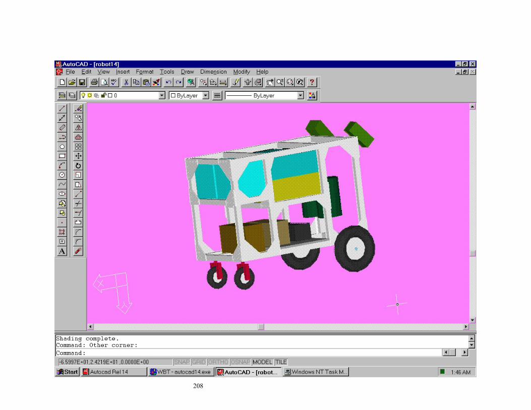
208

209

Appendix 4 Database Schema
210

References and Bibliography 1 T. A. Nguyen, T. C. Young, W. A. Perkins, T. J. Laffey, and D. Pecora, “A Knowledge based
design cheking guide,” Robotics and Expert Systems, Proceedings of the Third anuual Workshop
on Robotics and Expert Systems, ISA 1987, p.p. 149.
2 Ramachandran, N., Shah, A.,"Expert system Approach in Design of Mechanical Components,"
Computers in Engineering, Proceedings of the 1988 ASME International Computers in
Engineering Conference and Exhibition, Volume one, New York, 1988, p. 6.
3 Tai, K. K., Lin, Yui and Wang, L. X., "Knowledge Based Mechanical Spring Design," Computers
in Engineering, Proceedings of the Computers in Engineering Conference and the Engineering
Database Symposium, ASME 1995 , 1995, p.p. 851.
4 Mehdi, K. and Play, D., "An Integrated Process for Gearbox Design," Computers in Engineering,
Proceedings of the Computers in Engineering Conference and the Engineering Database
Symposium, ASME 1995 , 1995, p.p. 841.
5 Meunier, K. L. and Dixon, J. R., "Iterative Respecification: A Computational Model for
Hierarchial Mechanical System Design," Computers in Engineering, Proceedings of the 1988
ASME International Computers in Engineering Conference and Exhibition, Volume one, New
York, 1988, p.p. 25.
6 MathCAD is the registered trademark of MathSoft Inc.
7 AutoCAD is the registered Trademark of AutoDesk Inc.
8 80/20 AutoCAD library 80/20 Inc., The Industrial Erector Set, Columbia City, IN, 1998.
9 SIMULINK the registered Trademark of Math Works Inc.
10 MATLAB the registered Trademark of Math Works Inc.
11 Galil Inc, “DMC-1000 Technical Reference Guide Ver 1.1”, Sunnyvale, California 1993
12 IDEAS is the registered Trademark of SDRC Inc.
211
13 TC++ is the registered Trademark of Borland Systems Inc.
212
14 Umesh R. Nikam, “A Fault diagnostic system for an unmanned autonomous mobile robot”, M.S.
Thesis, University of Cincinnati, 1997
15 Visual basic 6.0 is the registered Trademark of Microsoft Inc.
16 Microsoft SQL Server is the registered Trademark of Microsoft Inc.
17 Jaideep Karnik, “Vibrational Analysis on Bearcat II”, MS Thesis, University of Cincinnati, 1999.
18 JVC Inc., “Camera Users Manual”, Indianapolis, Indiana 1985.
19 Iscan Inc., “RK-446-R Video Tracking System Manual”, Cambridge, Massachusetts 1993.
20 Tayib Samu, “Vision System for Three Dimensional Line Following of an Unmanned
Autonomous Mobile Robot”, MS Thesis, University of Cincinnati, 1996.
21 Galil Inc, “DMC-1000 Technical Reference Guide Ver 1.1”, Sunnyvale, California 1993.
22 80/20 Inc., The Industrial Erector Set, Columbia City, IN, 1998.