edition 01/98
TRANSCRIPT

ACCESS FLOORING IN BUILDINGS
SAFETY GUIDLINES
FOR ACCESS FLOORING
Edition 01/98
Bundesverband Systemböden e.V
Safety guidelines for access flooring Edition 01/982
Issued by:
Bundesverband Systemböden e.V.Düsseldorf
Reprinting, also of extracts, is prohibited
All rights reserved
1998, BVS, Düsseldorf
Bundesverband Systemböden e.V.40574 DüsseldorfNiederkasseler Straße 60TEL: (0211) 55 61 66FAX: (0211) 55 64 66http://www.systemboden.de
Düsseldorf, in January 1998

Safety guidelines for access flooring Edition 01/98 3
With these safety guidelines, the Bundesverband Systemböden e.V (Germanassociation of flooring systems) is establishing a standard in safety technology, whichis a necessary precondition for the manufacture of access floors and for the safety inuse.
Access flooring systems are designed and manufactured in accordance with the safetyrequirements and are undergoing constant technological development. For thisreason, the technical requirements which are the subject of the safety guidelines mustbe regularly brought in line with the state of the art in technology.
Only access flooring systems which, above and beyond complying with the usualmanufacturing standards, meet the requirements for safety technology of theBundesverband Systemböden with regard to their design and stability, materials andprocessing, and thus durability, are awarded with the BVS safety certificate for accessfloors.
The safety standard is under constant supervision by the manufacturers continuosfactory control plus regular external supervision by independent test institutes andexperts commissioned by the Bundesverband.
This monitoring of safety standards ensures that the necessary criteria for the safety inuse are complied with, thus establishing reliable guidelines for the selection of accessfloors.
The installation of access floors which has been awarded with the safety certificategives the user or client the guarantee that he is complying to the highest degreepossible with the very latest standards with regard to safety, liability and the protectionof labour.
These guidelines are under constant revision to keep pace with the state of the art intechnical progress. The latest version can be obtained from the BundesverbandSystemböden, Düsseldorf.
Bundesverband Systemböden e.V.
Safety guidelines for access flooring Edition 01/984
CONTENTS Page
Safety Seal Access flooring 2Preface 3Contents 4
1. General information 61.1 Field of application 61.2 Explanation of terms 61.3 General premises 71.4 Materials 71.5 Material quality 81.6 Hazardous substances 81.7 Climatic conditions 81.8 Special measures 81.9 Special access flooring panels 81.10 Test conditions 91.11 Safety-relevant industrial standards and guidelines 9
2. Safety requirements 112.1 Safety requirements for access flooring elements 112.1.1 Design load 112.1.2 Load grades 122.1.3 Requirements to the load bearing capacity of access 13
flooring elements2.1.4 Procedure for testing 132.1.4.1 Test sequence 132.1.4.2 Testing 152.2 Safety requirement for access flooring panels 152.2.1 Dimensional accuracy 152.2.1.1 General information 152.2.1.2 Requirements 162.2.1.3 Procedure for testing 172.2.2 Deflection 172.2.2.1 Requirements 172.2.2.2 Procedure for testing 172.2.3 Permanent deflection and permanent local deformation 182.2.3.1 Requirements 182.2.3.2 Testing of permanent deflection 182.2.3.3 Testing for remaining, local deformation 19

Safety guidelines for access flooring Edition 01/98 5
2.2.4 Corrosion-proofing for access flooring panels 202.2.4.1 Requirements 202.2.4.2 Procedure for testing 212.2.5 Floor coverings 212.2.5.1 General information 212.2.5.2 Requirements with regard to adhering 222.2.5.3 Testing the resistance to peeling 222.3 Safety requirements for the substructure 232.3.1 General information 232.3.2 Vertical eccentric load on the substructure 242.3.2.1 Requirements 242.3.2.2 Testing 252.3.3 Horizontal load on the pedestals 262.3.3.1 Requirements 262.3.3.2 Testing 282.3.4 Protection against corrosion 292.3.4.1 Requirements 292.3.4.2 Testing 302.4 Electrostatics 302.4.1 Requirements 302.4.2 Procedure for testing 302.4.2.1 Testing the earth diversion resistance RE and REF 312.4.2.2 Testing the resistance at the site border RST 322.5 Fire protection 332.5.1 Requirements 332.5.1.1 Combustibility 332.5.1.2 Fire resistance 332.5.2 Inspections 332.6 Acoustics 342.7 Hygiene 34
3. Qualification for the safety certificate 343.1 Safety certificate 343.2 Application, declaration of obligation 343.3 Initial testing 353.4 Monitoring by the manufacturer 353.5 Independent monitoring 353.6 Test reports 373.7 Designation 38

Safety guidelines for access flooring Edition 01/986
Safety guidelines for access floors
The safety guidelines for access floors lays down requirements with regard to thesafety and suitability of access flooring systems and with regard to the constructionand production of access flooring elements.
1. General
1.1 Field of application
These safety guidelines apply, for example, to access floors used• in offices and administrative areas,
• in EDP centres and peripheral rooms,• in work shops and work rooms for manufacture,
• in combination with hollow floor systems.
•
1.2 Explanation of terms
Access flooring systemA system used in the interior of buildings, which, under the whole of its area,incorporates an easily accessible installation cavity to accommodate all installations,all incoming and outgoing lines. This system uses ready-produced, modularcomponents. The access flooring system consists by linking (assembly in buildings)these individual components to an unite area.
Access flooring elementThe access flooring element is the smallest portable module of the access flooringsystem. The access flooring element consists basically of a access flooring panel anda substructure. The substructure, in turn, basically consists of four pedestals and thecorresponding supporting elements or pedestal head caps. The substructure may alsocomprise horizontal reinforcing elements, such as stringers.

Safety guidelines for access flooring Edition 01/98 7
Access flooring componentsIn particular, access flooring consists of components such as• access flooring panels, with or without floor covering;• access flooring pedestals for varying construction heights;
• access flooring stringers, for load-bearing and/or sealing and/or reinforcingpurposes;
• other system equipment such as pedestal head caps/ support elements, adhesive,linkage elements, bridging elements.
1.3 General premises
Where installed, access flooring is by its nature subject to constant stress. Therefore,its elements must fulfil certain preconditions. There follows a description of therequired characteristics and preconditions. The customer is required to pass on anyinformation on special requirements, particularly if these relate to safety specificationsin the outset to ensure that the design and construction of the access flooring meet theindividual requirements in each case. A specialist engineer should be involved in bothplanning and installation in order to co-ordinate the special requirements of the job inhand and the observation of the relevant safety standards.
1.4 Materials
The characteristics of the finished product depend on the characteristics of thematerials used. These materials must be suited to the purpose to which they areapplied. Fluctuations in dimension or characteristics as a result of changes intemperature and/or humidity may be specific to the material, in which case they aregiven physical factors and are appropriate to state-of-the-art technology. Adaption tothe ambient climatic conditions has to be taken in account during planing andconstruction. Thus, a minimum level of safety can be guaranteed.Access flooring components can, for example, be made of• organic materials• materials of mineral origin,
• materials of metallic origin,• synthetic materials,or of combinations of different materials.

Safety guidelines for access flooring Edition 01/988
1.5 Quality of materials
All materials used shall be subject to quality testing during production and processing,in order to ensure a constant level of product safety. At the least, test self certificates inaccordance with DIN 50049 will be required.
1.6 Hazardous substances
The materials must conform to legal requirements with regard to Dangerous MaterialsAct (GeFStoffV) and other applicable regulations and laws, e.g. all panels comprisingtimber-derived products must at least comply to emission grade E1.
1.7 Climatic conditions
As standard, the materials used in the access flooring components are intended tofulfil the requirements for use under normal climatic conditions. (Temperatures of 15 -25°C at a relative air humidity of 40-65%).
1.8 Special measures
For example, if the climatic conditions are expected to deviate from the normal climaticconditions for access floors, there are special safety precautions which are to be takenor can be arranged on request.If, for example, the flooring is used where corrosive liquids, gases or radiation are tobe expected, appropriate measures to ensure the safety of the access flooring systemmust be taken.
1.9 Special access flooring panels
In the case of special access flooring panels, special characteristics can be specified.These must be considered separately from the point of view of safety. Such specialpanels are, for example, cut-out panels, panels in association with electricalequipment, ventilation panels and panels whose length of the edges deviate from thegrid of the system or from the normal rectangular shape.

Safety guidelines for access flooring Edition 01/98 9
1.10 Test conditions
The test procedures described in these guidelines are carried out on themanufacturer's premises or in testing laboratories under predefined test conditions.This is necessary that test results are exact and reproducible.To evaluate individual test results, a confidence level of 95% is required.
1.11 Safety-relevant industrial standards and guidelines
• DIN 1052 - timber structures, design and construction• DIN 1055 - design loads in construction engineering
• DIN ISO 1101 - form and site tolerance• DIN 4102 - fire behaviour of building materials and components
• DIN 4103 - internal non-loadbearing partitions• DIN 4109 - soundinsolation in buildings, requirements and
verification• DIN 4149 - building structures in German seismic areas
• DIN 18 202 - dimensional tolerance in building construction, - buildings
• DIN 18 299 - general regulations for building work• DIN 18 334 - carpentry and joinery work
• DIN 18 331 - concrete- and reinforced concrete work
• DIN 18 353 - floor screed works• DIN 18 365 - work on floor coverings
• DIN 50 014 - air-conditioning equipment and its application• DIN 50 021 - spray-mist testing with various sodium chloride
solutions• DIN 50 049 - issuing works test certificates
• DIN 50 960 - electro-plating and chemical coatings; designations and specifications
Safety guidelines for access flooring Edition 01/9810
• DIN 50 961 - electro-plating• DIN 50 981 - magnetic procedures for measuring the thickness of
non-ferromagnetic layers on ferromagnetic material• DIN 51 953 - testing of organic floor coverings, testing the
conductance• DIN 51 963 - testing of organic floor coverings, cycle testing
• DIN 52 210 - test in building acoustics, airborne and inpact sound insolation
• DIN 54 345 - testing textiles, electrostatic performance• DIN 68 771 - sub-floors of wood chipboard
• DIN V ENV 1991-2-1 - basics of supporting framework design
• VDI 3762 - soundproofing with access and hollow flooring• Manual for hollow flooring from the Bundesverband Systemböden
• Safety guidelines for hollow flooring from the Bundesverband Systemböden• MBO Musterbauordnung (sample building ordinance)
• LBO Landesbauordnung (regional building ordinance)• NFPA 99
• VDE 0100 Part 610• RAL-RG 725/3 -electrical properties of elastic and textile floor
coverings• EU Construction Products Directive (CPD)
• Application-specific requirements and guidelines such as for clean rooms,shipbuilding, shelters etc.. in as far as relevant for a building

Safety guidelines for access flooring Edition 01/98 11
2. Safety requirements
2.1 Safety requirements for the access flooring element
2.1.1 Design loadWith regard to stability and strain, access floors have to be approached under aspectswhich differ from those of normal static because of the special static characteristics ofaccess flooring. In general, it is not the area load which are decisive for the safety of aaccess floor, but the point load.
The principle of design load is:load spacing > modular dimension
Loads where the points of load application are closer together than the modulardimension (grid) are to be taken together and their sum used for the calculation of thepoint load.The access floor is assigned to the individual load classes on the basis of its staticproperties.
Figure 1 : Position of possible load application points
!JULG GLPHQVLRQ
ORDG DSSOLFDWLRQ SRLQW �
SRVVLEOH ORFDWLRQ
RI IXWKHU ORDG
DSSOLFDWLRQ 3RLQWV
DSSOLFDWLRQ SRLQW
IRU IXUWKHU ORDG
SRVVLEOH ORFDWLRQ
ORDG DSSOLFDWLRQ SRLQW �

Safety guidelines for access flooring Edition 01/9812
When transporting articles with lift-trucks, fork-lift trucks and similar vehicles, pointloads are caused by their wheels. In the movement sequence, this is no longer a staticbut a dynamic load. For calculation purposes, the oscillation coefficient in accordancewith DIN 1055 must be taken into account:
point load to be applied = effective point load x oscillation coefficient ϕFollowing DIN 1055, the following oscillation coefficients can be applied:
manually operated transport devices: oscillation coefficient ϕ = 1.3
motor-driven transport devices: oscillation coefficient ϕ = 1.5Note:
Depending on the use, load states may occur which require oscillation coefficients of ϕ≥2.0.In addition, the wheel construction and the wheel material also have a decisiveinfluence on the oscillation coefficient. This must be taken into consideration whenplanning.
2.1.2 Load grades
Loadgrade
Nominalpoint load
[N]
Safety load 1
[N]
Examples of application
2 2000 4000 Offices which are not used by many people.
3 3000 6000 Normal office areas, telephone exchanges, lecturetheatres, school and treatment rooms, clean rooms
4 4000 8000 commercial EDP rooms and adjacent rooms,engineering offices, clean rooms
5 5000 10000 EDP rooms and office rooms with specialrequirements or which are frequented by manypeople, printing rooms, industrial floors in lightindustry, storerooms, workshops in light industry,clean rooms
6 2 6000 12000 Floors in rooms where industrial trucks are used,industrial and workshop floors, strongrooms, cleanrooms
1 Taking safety value ν = 2 into account2 For access flooring in individual cases with special requirements, further load grades can bedefined. For these load grades the ration is: Load grade (integer values) x 100 N = nominal pointload
Table 1 : Classification of load grades

Safety guidelines for access flooring Edition 01/98 13
2.1.3 Requirements to the load bearing capacity of access flooring elementsThe load bearing capacity is of decisive importance for the safety of a access flooringelement. The load bearing capacity is tested on the access flooring element in thetesting laboratory.In use, the components of a access flooring system should never be exposed to loadswhich reach their borderline values. The maximum value is predefined by the staticnominal point load.
A safety coefficient ν of 2 is required for a access flooring element, i.e. the safety loadcorresponds to the double nominal point load. The ultimate load determined bylaboratory testing must be > safety load.
2.1.4 Test procedure2.1.4.1 Test sequenceFor testing, the access flooring panel is laid on the substructure of the specific accessflooring system. The pedestals are firmly fixed to the base. The testing height isdetermined by the maximum nominal height and the maximum permissible adjustmentrange. The load is applied to the access flooring element via a indentor with an edgelength of 25 x 25 mm. The edges which have contact with the material may berounded to a maximum radius of 2 mm. During testing, the load is increasedcontinuously with a load increase of 100 N/s + 10 N/s.
The load is applied to pointsI-1 in the centre of the panelI-2 in the centre of the edge of the panelI-3 in the area close to the panel cornersI-4 in the area of a ribbed field (field area)II-5 simultaneously in the are of the panel corner and on the diagonal of
the panelor at any point the institute carrying out the test well founded defined as the weakestpoint on the access flooring element. The institute will state its reasons for theselection of this point. (see also Figure 2)If the system used means that it is problematical to apply the load at one of thepreselected load application points, the testing institute may choose to apply the loadat a point in the direct vicinity of the preselected load application point.

Safety guidelines for access flooring Edition 01/9814
Figure 2: Load application points I-1 to II-5
ORDG SRLQW ,��
H[DPSOH RI ILHOG VHFWLRQV IRU
/RDGSRLQW ,��
5DQJH IRU
IRU WHVWLQJ LQ WKH FRUQHU DUHD([DPSOH RI SRVLWLRQ RI ORDG SRVLWLRQ ,��
/RDG SRLQW ,���
W WKLFNQHVV RI SDQHO
W
/RDG SRLQW ,,���
�
/RDG SRLQW ,���
�
/RDG SRLQW ,���
/RDG SRLQW ,���
���
���
W
�
W
�
W
3DQHO VXSSRUW
W
���
�
W
5DQJH IRU/RDGSRLQW ,��
/HQJKWRIHGJH

Safety guidelines for access flooring Edition 01/98 15
2.1.4.2 TestingMeasurements are taken to ascertain whether the safety load is reached at the loadapplication points defined in 2.1.4.1.To effect testing, an preloading of up to the nominal point load is applied and the panelthen relieved.The load is increased continuously until the nominal point load is increased by thevalue of the safety coefficient.For load application point I-2, the vertical movement of the access flooring panel underthe nominal point load is measured and documented, starting from the originalposition.
2.2 Safety requirements for access flooring panels
2.2.1 Dimensional accuracy2.2.1.1. General informationThe dimensional accuracy of access flooring panels is relevant to the safety as theoverall surface of the panels will not hold together correctly if the panels do not fittogether properly. Also, there is a danger of stumbling as a result of height differencesdue to e.g. deviations in thickness.When checking the dimensional accuracy, the following geometrical measurementsare taken on access flooring panels during or immediately after manufacture. Shapeand position tolerance levels are defined in accordance with DIN ISO 1101.
Figure 3: Dimensions of a access flooring panel
l
l
�J
�
l
HGJH %
%
U
�
�
$
�J
J�
(GJH $$
W
�
J�
�
J�
&
l
(GJH '
$
(GJH &
S
�
�
$
�
J
'
U $
�J
3DQHO WZLVW

Safety guidelines for access flooring Edition 01/9816
2.2.1.2 Requirements
Symbols Column 1[mm]
Column 2[mm]
DIMENSIONS RELATING TO SIZE
1. Lenght of sides l A
... l D
± 0,3(± 0,4)
± 0,4(± 0,6)
2. Squaring of the faces B and Dto side edge A r
0,4(0,5)
0,6(0,7)
3. Parallelism of face C to face Ap 0,4(0,5) 0,6(0,7)
4. Straightness of the four facesin the area of the panel touchingedges
g3 0,3(0,5)
0,5(0,7)
DIMENSIONS RELATING TO THICKNESS
5. Panel thickness at the contactcorners*)
t ± 0,3 ± 0,5
6. panel twist on one corner *) v0,5
(0,8)0,8
(1,0)
7. Straightness of the upper panelsurface at the edges *)
g1 0,5(0,8)
0,8(1,0)
8. Straightness of the upper panelsurface in the area of thediagonals *)
g2 0,9(1,4)
1,2(1,8)
• Measurement tolerance levels for floor panels with edge lengths of 500 mm to650 mm
• Measurement tolerance levels for edge lengths > 650 in brackets• *) without influence from the floor coverings• COLUMN 1 Special measurement tolerance levels with increased optical
requirements (for e.g. application of floor coverings which emphasise seams)• COLUMN 2 Safety-relevant measurement tolerance levels (for example,
application of textile floor coverings and coverings which cover seams)
Table 2 : Dimensional tolerances

Safety guidelines for access flooring Edition 01/98 17
2.2.1.3 Test procedureThe mesurements are taken using appropriate gauges and measuring devices. Inaccordance with the general rules of measurement, the applied measuring instrumentsshould show an accuracy of less than 10% of the measurement tolerance levels asdefined in table 2.
2.2.2. Deflection2.2.2.1 RequirementsThe geometrical positions of the load application points are shown in 2.1.4.The maximum deflection at load application point I -2 (middle of panel edge) has to beas following:
l / /300 > average value of deflection measurements < 2.5 mm, wherel = length of panel edge.
The maximum deflection at load application point I -1 (centre of panel) has to be asfollowing:
l a /300 > average value of deflection measurements < 3.5 mm, wherel a = length of panel diagonal.
2.2.2.2 Test procedureDuring testing, the access flooring panels lie on solid support blocks arranged in onelevel surface. The bearing surface is formed by the 90° section of a steel cylinder witha diameter of 90 mm as a corner support.Deflection is measured in the centre of the load application on the underside of theaccess flooring panel and when the nominal point load is reached.The load is applied to the access flooring element via an indentor with an edge lengthof 25 x 25 mm. The edges of the indentor which contact the surface of the panel maybe rounded to a maximum radius of 2 mm. The load is increased continuously duringthe test, with a load increase of 100 N/s + 10 N/s.In the case of ribbed access flooring panels, a measuring frame may be used tomeasure the degree of deflection, as shown in Figure 4.

Safety guidelines for access flooring Edition 01/9818
Figure 4: Measurement of deflection on ribbed panels
If stringers are used to increase the load strength of the access flooring panel to betested, these stringers must be included in the test for deflection.
2.2.3 Permanent deflection and permanent local deformation2.2.3.1 Requirements
Permanent deflection[mm]
Permanent local deformation[mm]
0,5 0,8
applies to all panel typesapplies to panels with
ribbed supporting structureTable 3: Maximum values for permanent deflection and permanent local deformation after
removal of the nominal point load
2.2.3.2 Testing for permanent deflectionThe nominal point load is applied to the access flooring panels at the critical load pointfor deflection and for a period of 15 minutes.The deflection is measured in the centre of the load application point on the undersideof the access flooring panel and when the static nominal point load is reached.The load is applied to the access flooring panel via a indentor with an edge length of25 x 25 mm. The edges of the testing stamp which contact the panel may be roundedto a maximum radius of 2 mm.
The load has to be increased continuously during the test, with a load increase of 100N/s + 10 N/s.
SHUPDQHQW GHIOHFWLRQ
PHDVXULQJ JDXJHPHDVXULQJ EULGJH
LQGHQWRU
GHIOHFWLRQ
SHUPDQHQW

Safety guidelines for access flooring Edition 01/98 19
In the case of ribbed access flooring panels, a measuring bridge can be used tomeasure the deflection, as shown in Figure 4.
The permanent deflection is measured 5 Minutes after the load is released. Themaximum permissible values are listed in table 3.
2.2.3.3 Testing for permanent local deformationIt is only necessary to measure the degree of permanent localised deformation onaccess flooring panels of ribbed construction.
Testing is carried out at the most critical load point for deformation in a field section.The nominal point load is applied to the access flooring panel for a period of 15minutes via the indentor (see 2.2.3.2). The permanent local deformation is measured 5minutes after the load has been released. The base dimension b of the measuringdevice corresponds to the clearance between, for example, ridges. The maximumpermissible tolerance level is listed in table 3.
Figure 5 : Measuring the degree of permanent localised deformation
2.2.4 Corrosion - proofing for access flooring panels2.2.4.1 Requirements

Safety guidelines for access flooring Edition 01/9820
In order to guarantee continual compliance with the safety requirements, all corrodingmaterials in the access flooring panels must be corrosion - proofed.The corrosion - proofing must fulfil the following requirements:The quality of the corrosion-proofing must correspond to a 5 µm electropaneld zinccoat with any chromating (designation X in accordance with DIN 50960 Part 1). Thiscorrosion-proofing should be in accordance with an expected stress of stage 1 (light),in compliance with DIN 50961.For normal applications, materials of non-ferrous metals like, for example, aluminium,copper or brass alloys as well as stainless steels need no additional corrosion-proofing.
Zinc platingZinc plating and chromatised zinc plating with a thickness which deviates from therequirements are to be considered as equivalent, without corrosion testing, if theduration as defined in DIN 50961 table 1 of the salt spray testing of this plating inaccordance with DIN 50021 SS is at least 48 hours.
Alternative protectionAll corrosion protection procedures are permissible in as far as they comply with theabove-listed requirements in the degree of protection they offer. This must beascertained and documented in the initial testing stage. The effectivity of the protectionis tested using a testing body by salt spray testing in accordance with DIN 50021 - SSwith a test duration of 48 hours. The aim of this test is to ascertain the necessarythickness of the plating for the alternative protection process. A list of permissibletypes of protection with the corresponding plating thicknesses will be drawn up by thetesting institute.
Special requirementsFor special application areas, special measures must be defined and tested in eachcase. Such special application areas are, for example, developing rooms forphotographic and film material, laboratories, testing rooms, clean rooms, rooms withspecial requirements.
ExceptionsThread surfaces, fuse elements and standardised parts such as nuts, spring

Safety guidelines for access flooring Edition 01/98 21
washers, serrated lock washers, sheet metal counternuts, crown gears etc.. must behave verifiably received the corrosion-proofing which is usual for such mass-producedparts (galvanising, black finishing etc..). No testing is carried out. The use of such partsis documented in the test report.
2.2.4.2 Procedure for testingThe thickness of the layers on all components used in the construction must bemeasured to establish whether the required degree of corrosion-proofing is given. Thethickness of the layers is measured in various places spread evenly over thecomponent part. The average layer thickness must be equivalent to at least therequired thickness, depending on the type of protection, in each measuring location.Measurements are taken using a measuring device which works according to theprinciples of magnetic measuring. (DIN 50 981).
2.2.5 Floor coverings2.2.5.1 General informationPeeling floor coverings represent a hazard. This means that the adhesion of the floorcovering is a safety-relevant criterion. The adhesion of the floor coverings must complywith the stipulations of DIN 18365 'Work on floor coverings', and the coverings mustretain their essential basic properties after processing. The individual characteristics ofthe floor coverings when used for their intended purpose must be adapted to conformto the special requirements for use with access flooring systems, and self certificatesin accordance with DIN 50049 must be obtained from the manufacturer to attest thatthis has been done. The floor coverings used must conform at least to the relevantproduct and material standards in each case.
Textile floor coveringsDue to the great variety of manufacturing processes, materials and dyeing methods forfloor coverings and the special requirements placed on them when they are applied toaccess flooring panels and in their subsequent use in conjunction with such panels, itmust be established that the coverings are suitable for use on access floors.Safety requirements for textile floor coverings:a) The dimensional stability of the coverings once they have been glued down must
be retained after appropriate cleaning.b) Coverings with foam backings are not permissible.c) The backing must be firmly linked with the back of the covering.d) Peeling values of > 0.8 N/mm must be possible without the backing splitting.
Elastic floor coveringsAs in the case of the textile floor coverings, the various materials (PVC, caoutchouc,linoleum etc..) must be firmly glued to the access flooring panels.

Safety guidelines for access flooring Edition 01/9822
The dimensional deviation when the floor coverings before application are tested inaccordance with DIN 51 963 (three measuring cycles at 80° C) must not be more than0.1%.
Other floor coveringsSome floor coverings used on access floors cannot be evaluated in the course of agenerally valid safety assessment. Such floor coverings are, for example,:
natural and synthetic stoneHPL (laminated covering)parquet flooringflexible coveringceramic coveringsmetal-layered flooring
For these materials, the suitability must be tested for each individual case, payingattention to the relevant material standards (or, where appropriate, with reference tothe individual project.
2.2.5.2 Requirements with regard to gluingThe test for resistance to peeling examines the suitability of adhesive methods fortextile and elastic floor coverings.The resistance to peeling (arithmetical average) of a access flooring panel (two teststrips) must be at least 0.8 N/mm. Each individual test strip must have a resistance of> 0.65 N/mm. Over a measured lenght of 100 mm, the average value of the resistanceto peeling may not drop below 0.4 N/mm.
2.2.5.3 Testing the resistance to peelingIn order to assess the resistance to peeling, two test strips are cut from the accessflooring panel to be tested, as shown in Figure 6.The strips are of the following size:
width of strip b = 50 mmlength of strip s> 0.5 x edge length l
The arrows in Figure 6 show the direction in which peeling is effected during the test.

Safety guidelines for access flooring Edition 01/98 23
Figure 6 : Arrangement of the test strips from a access flooring panel for testing of the resistanceto peeling
During the test, the test strip is peeled off perpendicular to the access flooring panel ata constant sped of 100 mm/min + 10 mm/min and the peeling force measuredcontinuously over the whole length of the test strip. The average resistance to peelingfor one test strip can then be calculated as follows:
average peel resistance = average peeling forcewidth of test strip
2.3 Safety requirements for the substructure
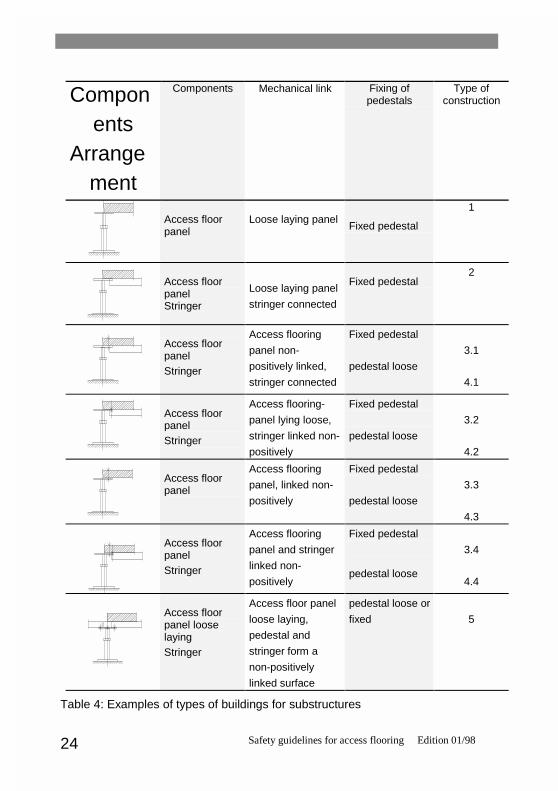
2.3.1 General informationThe requirements on the components of the substructure listed hereafter particularlysafety characteristics.In use, each access flooring system must absorb and conduct vertical and horizontalforces. When setting the requirements the type of construction must be taken intoconsideration.
E
l
V
V
Safety guidelines for access flooring Edition 01/9824
Components
Arrangement
Components Mechanical link Fixing ofpedestals
Type ofconstruction
Access floorpanel
Loose laying panelFixed pedestal
1
Access floorpanelStringer
Loose laying panel
stringer connected
Fixed pedestal2
Access floorpanelStringer
Access flooring
panel non-
positively linked,
stringer connected
Fixed pedestal
pedestal loose
3.1
4.1
Access floorpanelStringer
Access flooring-
panel lying loose,
stringer linked non-
positively
Fixed pedestal
pedestal loose
3.2
4.2
Access floorpanel
Access flooring
panel, linked non-
positively
Fixed pedestal
pedestal loose
3.3
4.3
Access floorpanelStringer
Access flooring
panel and stringer
linked non-
positively
Fixed pedestal
pedestal loose
3.4
4.4
Access floorpanel looselayingStringer
Access floor panel
loose laying,
pedestal and
stringer form a
non-positively
linked surface
pedestal loose or
fixed 5
Table 4: Examples of types of buildings for substructures

Safety guidelines for access flooring Edition 01/98 25
2.3.2 Vertical eccentric load on the substructure2.3.2.1 RequirementsTesting at the nominal point load is defined as a safety characteristic independent ofthe element test, in order to allow for substructure testing to accompany theconstruction process.With eccentric loading with the nominal point load, the plastic deformation of thepedestal head must not exceed 0.3mm (measured at a distance of 45 mm from thecentre of the pedestal head). For substructure of construction type 5, there is no suchrequirement.In addition, the permanent change in length of the pedestal must be smaller than 0.3mm.
TestingTo test the substructure, the pedestals are tested as one construction component,standing free at maximum nominal height and the highest permissible adjustmentrange. The base panel is fixed firmly to the testing device.
Figure 7: Testing the vertical eccentric load
0RXQW
0RXQW)

Safety guidelines for access flooring Edition 01/9826
In order to test the vertical eccentric load, the nominal point load is applied to thepedestal via a testing stamp and a jointed, bearing-mounted mount. Any supportedelements or pedestal-head pads are included in the test.
The load is applied centrally via a 50 x 50 mm testing stamp which is positioned on thecorner of the load application panel (holder). A 20 mm rubber element with a hardnessof 60° Shore D is inserted between the load application panel and the pedestal head.
The load is increased continuously at 100 N/s + 10 N/s, until the stated nominal pointload is reached.After the application of the load, the permanent length change is in the middle of thepedestal and the plastic deformation of the pedestal head are measured. The changein the measurement is defined before and after the application of the nominal pointload.
Figure 8 : An example of possible plastic deformation of the pedestal head
2.3.3 Horizontal load on the pedestals2.3.3.1 RequirementsIn practical use, every access flooring system is loaded horizontaly. The force can beapplied to the system via the access flooring panel or via the substructure.
PD[����

Safety guidelines for access flooring Edition 01/98 27
The requirements under horizontal load serve exclusively to evaluate the staticstrength of the components, not of the composite adhesive strength of the normalattachment of the components to the raw floor in assembly.Table 4 shows a selection of different types of building.
Load grade Horizontal nominal load Fh Reduction coefficient for type
[N] 1 2 3,4 u. 52 60 1,0 0,5 03 90 1,0 0,5 04 120 1,0 0,5 05 150 1,0 0,5 0
6 andhigher
Nominal point load x 0,03 1,0 0,5 0
Table 5: Horizontal loads and reduction coefficients, depending on
The horizontal nominal testing load Fp is calculated on the basis of the nominalhorizontal load Fh x reduction coefficient.The permanent deformation (crookedness) after the application of the nominalhorizontal testing load must be < 1% in average of a test batch.The safety coefficient in the direction of the horizontal load must be at least 2.In the case of substructures of building type 1, the maximum deflection AL of thepedestal head must not exceed D/2 at double nominal horizontal load Fh. (D =diameter of the pedestal head; in the case of rectangular pedestal heads, the smallervalue applies).
Necessary tests types 1 2 3,4 und 5
1. The application of nominal horizontal testing load Fp √ √2. The measurement of the permanent deformation after loading √ √3. The application of the 2-fold nominal horizontal load Fp √ √4. The measurement of the deflection at the pedestal head √5. Testing of the cohesion of the individual components under 2-fold
nominal horizontal load Fh
√
Table 6: Testing depending on the type of building
2.3.3.2 TestingThe pedestals are to be tested free-standing as a total construction part at maximumnominal height and the highest permissible adjustment range. The base panel is firmlyfixed to the testing device. The size of the nominal horizontal testing load Fp isdetermined according to load grade and the type of building, in accordance with table5. The load is effective on the pedestal head.

Safety guidelines for access flooring Edition 01/9828
The necessary tests are listed in table 6.
Figure 9 : Testing under the nominal horizontal testing load Fp
In the case of access flooring systems for buildings of type 3, 4 and 5, with form-fit ornon-positive linking of the individual components for the transmission of horizontalforces, these links are tested under 2-fold nominal horizontal testing load Fh. The link(e.g. screw, stop catch......) must not fail under this load.
Figure 10 : Example of form-fit and non-positive links
2.3.4 Protection against corrosion2.3.4.1 RequirementsAll materials which are at risk from corrosion on access flooring panels must becorrosion-proofed. This is necessary to maintain the safety-relevant componentcharacteristics. The following are the requirements for corrosion-proofing.The quality of the corrosion-proofing for the maintenance of product safety mustcorrespond to an electropaneld zinc coating with a thickness of 8 µm with any
)3
SHGHVWDO KHDG
K� [ )
EROWHG
K� [ )

Safety guidelines for access flooring Edition 01/98 29
chromating (designation X in accordance with DIN 50960 Part 1). This corrosion-proofing is equivalent to an expected corrosion level of stage 2 (moderate) inaccordance with DIN 50961.For normal applications, materials of non-ferrous metals such as aluminium, copperand messing alloys and stainless steel need no additional corrosion-proofing.
Zinc platingZinc platings and chromatised zinc platings of thicknesses other than those requiredare to be considered as equivalent without corrosion testing, if the testing period statedin table 1 of DIN 50961 for the salt spray test in accordance with DIN 50021 is at least72 hours.
Alternative protectionAll corrosion protection procedures are permissible in as far as they comply with theabove-listed requirements in the degree of protection they offer. This must beascertained and documented in the initial testing stage. The effectivity of the protectionis tested using a testing body by salt spray testing in accordance with DIN 50021 - SSwith a test duration of 72 hours. The aim of this test is to ascertain the necessarythickness of the plating for the alternative protection. A list of permissible types ofprotection with the corresponding plating thicknesses will be drawn up by the testinginstitute.
Special requirementsFor special application areas, special measures must be defined and tested in eachcase. Such special application areas are, for example, developing rooms forphotographic and film material, laboratories, testing floors, clean rooms, rooms withspecial requirements.
ExceptionsThread surfaces, fuse elements and standardised parts such as nuts, spring washers,serrated lock washers, sheet metal counternuts, crown gears etc.. must be haveverifiably received the corrosion-proofing which is usual for such mass-produced parts(galvanising, black finishing etc..). No testing is carried out. The use of such parts isdocumented in the test report.
2.3.4.2 TestingThe thickness of the layers on all components used in the construction must bemeasured to establish whether the required degree of corrosion-proofing is given. The

Safety guidelines for access flooring Edition 01/9830
thickness of the layers is measured in various places spread evenly over thecomponent part. The average layer thickness must be equivalent to at least therequired thickness, depending on the type of protection, in each measuring location.Measurements are taken using a measuring device which works according to theprinciples of magnetic measuring. (DIN 50 981).
2.4 Electrostatics
2.4.1 RequirementsThe requirements with regard to the electrostatic properties of access floors are to belaid down separately for each area of application.For example, limit values for derivation ability are also predetermined by themanufacturers of electronic equipment.In defined areas, special requirements will have to be fixed with regard to theinsulating properties of the floor constructions.For requirements with regard to insulating properties, see VDE 0100 Part 610.
2.4.2 Procedure for testingThe testing regulations are laid down in DIN 51 953 for elastic coverings and in DIN 54345 for textile coverings; for the site border resistance in VDE 0100 Part 610.The measurements are read on the floor panel including the substructure. Formeasurement, the panel is laid on four pedestals of the substructure. Conducting padelements or pedestal head pads are to be inserted between the floor panel and thepedestals as they are when they are laid down in the building.Tests are carried out in the laboratory in a standard operating environment inaccordance with DIN 50014 - 23/50 - 2 (23° C room temperature; 50% relative airhumidity).

Safety guidelines for access flooring Edition 01/98 31
The climatic conditions during measurement are recorded in the test report.All other test conditions are described in the standards listed above and in thefollowing chapters.
2.4.2.1 Testing for the earth diversion resistance RE and REF
Measurements are to be taken at at least five positions on the floor panel.Figure 11 shows the test set-up for laboratory testing.
Figure 11 : Test set-up for testing the earth diversion resistance
���
���
�
�
0HDVXULQJ�,QVWUXPHQW

Safety guidelines for access flooring Edition 01/9832
2.4.2.2 Testing the resistance at the site border RSTFigure 12 shows the test set-up for laboratory tests on access flooring elements withmeasurements taken in the centre of the panel.
Figure 12 : Test set-up for testing the resistance at the site border
���NJ
�
�
0HDVXULQJ�,QVWUXPHQW

Safety guidelines for access flooring Edition 01/98 33
2.5 Fire protectionFire protection is laid down in DIN 4102.The class of building material defines the combustibility of building materials and thepossible spreading of fire in the material.The fire resistance classification defines the resistance of a component to the passageof fire, combustion gases and heat over a specified period of time, for the purpose ofpersonal safety and in order to keep avenues of escape and rescue open.
2.5.1 RequirementsGeneral requirements can be found, for example, in the respective regional buildingregulations and the guidelines 'fire-protection requirements for cavity floors and accessflooring'.
2.5.1.1 CombustibilityClassification according to a class of building materials combustibility is effected inaccordance with DIN 4102. The class of combustibility can be recorded on the safetycertificate.
2.5.1.2 Fire resistanceThis is attested via test certificate issued by official and authorised agencies. Theclassification of fire resistance can be recorded on the safety certificate.
2.5.2 TestingTesting of the fire-protection qualities is carried out in accordance with the establishedstandards and guidelines and in authorised institutes.

Safety guidelines for access flooring Edition 01/9834
2.6 AcousticsThe relevance of soundproofing for safety is documented in the general and specificnoise protection requirements.Access flooring cushions airborne and footfall sound. The requirements are laid downin DIN 4109 and concrete planning stipulations or regulations. The classification ofconcrete numerical values is based on laboratory evidence and can be included in thesafety certificate as values for horizontal and vertical airborne and footfall sound.
2.7 HygieneAccess flooring constructions include cavities which are partly isolated from the roomand exterior air.In order to fulfil the necessary hygiene requirements, it should be ensured that therelative air humidity in these floor cavities is one average less than 80%.
3. Qualification for the safety certificateFor initial and external testing, the Bundesverband Systemböden commissions neutralexperts or recognised testing institutes.
3.1 Safety certificateThe certification commission of the Bundesverband Systemböden e. V. awards andcan withdraw the safety certificate.All details are subject to the procedures of the certification commission.
3.2 Application, declaration of obligationWith the application for a safety certificate, the applicant also submits a binding andunrestricted declaration that the access flooring system specified in the applicationfulfils all requirements with reference to safety in accordance with these guidelines.

Safety guidelines for access flooring Edition 01/98 35
3.3 Initial testingThe access flooring system for which a safety certificate has been applied for is to besubjected to initial testing on the instructions of the certification commission inconsultation with the testing institute.The certification commission orders the initial testing.The testing official will draw up a report on the initial test. The applicant and thecertification commission receive one copy each.The certification commission makes its decision on whether the safety requirementsare fulfilled on the basis of this test report.
3.4 Monitoring by the manufacturerEach applicant awarded a safety certificate is responsible for ensuring that the safetyguidelines are complied with. To do so, supervision measures which are appropriate intheir number, frequency and scope must be taken. Such measures are to be carefullydocumented. The records are to be kept for 5 years and to be submitted duringmonitoring arranged for by the association.
3.5 Third body controlThe Bundesverband Systemböden e. V. enters into a supervision contract with aneutral expert or a recognised testing institute to carry out the independent monitoring.This independent monitoring comprises inspections to evaluate whether the monitoringby the manufacturer himself is effected continually and correctly, whether themonitoring is documented and whether the necessary evaluations are carried out.The testing institute submits a report to the certification commission.

Safety guidelines for access flooring Edition 01/9836
Initial testing 2 Independent monitoring 1
By a neutral testing agencycommissioned by the
BundesverbandSystemböden e.V.
By a neutral testing agencycommissioned by the
BundesverbandSystemböden e.V.
Access flooring elementSafety point load
in accordance with article2.1
annual inspection
Access flooring panelDimensional accuracy
in accordance with article2.2.1.3
annual inspection
Access flooring panelDeflection
in accordance with article2.2.2.2
annual inspection
Access flooring panellocal deformation
in accordance with article2.2.3.3
annual inspection
Access flooring panelCorrosion-proofing
in accordance with article2.2.4.2
annual inspection
Access flooring panelFinish of floor coverings
in accordance with article2.2.5
annual inspection
Substructurevertical eccentric load
in accordance with article2.3.2.2
annual inspection
SubstructureHorizontal load on thepedestals
in accordance with article2.3.3.2
annual inspection
SubstructureCorrosion-proofing
in accordance with article2.3.4.2
annual inspection
Electrostatics in accordance with article2.4.2
verification that constructioncontinues in compliance
with the requirements
Fire protection proof to be provided inaccordance with DIN 4102
verification that constructioncontinues in compliance
with the requirements
Soundproofing proof to be provided inaccordance with DIN 4109
verification that constructioncontinues in compliance
with the requirements
1 Inspection of records of monitoring by the manufacturer
2 3 tests per test characteristic of the access flooring system to be tested
Table 7 : Supervision measures

Safety guidelines for access flooring Edition 01/98 37
3.6 Test reportsThe test methods and procedures are to be recorded, if necessary, in the form ofdrawings.The test reports should contain:
- Name of manufacturing company- Test object and description of material, type- Test criterion- Test apparatus, test procedure- Details of extraction and number of test samples- Readings, if necessary with intermediate values- Evaluation and results- Date of test and location of test
If the results of the test do not comply with the required values, a repeat test is to becarried out at an interval specified by the certification commission.

Safety guidelines for access flooring Edition 01/9838
3.7 DesignationAccess flooring which complies with the requirements of these safety guidelines areawarded the following stamp:
The safety certificate is used exclusively in accordance with the instructions for theapplication and the use of the safety certificate of the Bundesverband Systembödene.V..