ee 477 final report - college of engineering - purdue … · web viewit may also be indicative of a...
TRANSCRIPT
ECE 477 Final ReportSpring 2007
Team Code Name: Sounds Good Team ID: 7
Team Members (#1 is Team Leader):
#1: Joe Land Signature: _________________________ Date: _________
#2: Ben Fogle Signature: _________________________ Date: _________
#3: James O’Carroll Signature: _________________________ Date: _________
#4: Elizabeth Strehlow Signature: _________________________ Date: _________
Joe Land
Ben Fogle
James O’Carroll
Elizabeth Strehlow

ECE 477 Final Report Fall 2006
-ii-

ECE 477 Final Report Fall 2006
REPORT EVALUATION
Component/Criterion Score Multiplier Points
Abstract 0 1 2 3 4 5 6 7 8 9 10 X 1
Project Overview and Block Diagram 0 1 2 3 4 5 6 7 8 9 10 X 2
Team Success Criteria/Fulfillment 0 1 2 3 4 5 6 7 8 9 10 X 2
Constraint Analysis/Component Selection 0 1 2 3 4 5 6 7 8 9 10 X 2
Patent Liability Analysis 0 1 2 3 4 5 6 7 8 9 10 X 2
Reliability and Safety Analysis 0 1 2 3 4 5 6 7 8 9 10 X 2
Ethical/Environmental Impact Analysis 0 1 2 3 4 5 6 7 8 9 10 X 2
Packaging Design Considerations 0 1 2 3 4 5 6 7 8 9 10 X 2
Schematic Design Considerations 0 1 2 3 4 5 6 7 8 9 10 X 2
PCB Layout Design Considerations 0 1 2 3 4 5 6 7 8 9 10 X 2
Software Design Considerations 0 1 2 3 4 5 6 7 8 9 10 X 2
Version 2 Changes 0 1 2 3 4 5 6 7 8 9 10 X 1
Summary and Conclusions 0 1 2 3 4 5 6 7 8 9 10 X 1
References 0 1 2 3 4 5 6 7 8 9 10 X 2
Appendix A: Individual Contributions 0 1 2 3 4 5 6 7 8 9 10 X 4
Appendix B: Packaging 0 1 2 3 4 5 6 7 8 9 10 X 2
Appendix C: Schematic 0 1 2 3 4 5 6 7 8 9 10 X 2
Appendix D: Top & Bottom Copper 0 1 2 3 4 5 6 7 8 9 10 X 2
Appendix E: Parts List Spreadsheet 0 1 2 3 4 5 6 7 8 9 10 X 2
Appendix F: Software Listing 0 1 2 3 4 5 6 7 8 9 10 X 2
Appendix G: FMECA Worksheet 0 1 2 3 4 5 6 7 8 9 10 X 2
Technical Writing Style 0 1 2 3 4 5 6 7 8 9 10 X 8
CD of Project Website 0 1 2 3 4 5 6 7 8 9 10 X 1
TOTAL
-iii-
Comments:

ECE 477 Final Report Fall 2006
TABLE OF CONTENTS
Abstract 1 1.0 Project Overview and Block Diagram 1 2.0 Team Success Criteria and Fulfillment 4 3.0 Constraint Analysis and Component Selection 5 4.0 Patent Liability Analysis 9 5.0 Reliability and Safety Analysis 10 6.0 Ethical and Environmental Impact Analysis 13 7.0 Packaging Design Considerations 16 8.0 Schematic Design Considerations 18 9.0 PCB Layout Design Considerations 2010.0 Software Design Considerations 2211.0 Version 2 Changes 2512.0 Summary and Conclusions 2513.0 References 26Appendix A: Individual Contributions A-1Appendix B: Packaging B-1Appendix C: Schematic C-1Appendix D: PCB Layout Top and Bottom Copper D-1Appendix E: Parts List Spreadsheet E-1Appendix F: Software Listing F-1Appendix G: FMECA Worksheet G-1
-iv-

ECE 477 Digital Systems Senior Design Project Spring 2007
Abstract
The Digital Steerable Sound System (DS3) is designed to digitally steer sound through a
pair of stationary loudspeakers. Each loudspeaker element will have its own delay and volumes
control settings to direct the sound. The modern design will also incorporate a control box with a
user interface. This interface will allow the user to set up the speakers in a non-idealized room
and have a clear stereo image projected towards a desired location. These loudspeakers will also
be time-aligned to enhance their performance.
1.0 Project Overview and Block Diagram
The idea behind the Digital Steerable Sound System (DS3) was to create a digitally
steering loudspeaker available at the consumer level. Since the sound can be pointed in different
directions, the speakers can be placed in non-ideal locations. Effectively, the sound is
independent of the acoustics of the room and can be limited to only the intended users. The set
of two loudspeakers and control box will be easy to use and modern in design.
Each tower contains eight steering woofers and four subwoofers. The loudspeaker will
operate at nearly the full audible spectrum. The control box houses a user interface that allows
the user to adjust the settings of the loudspeakers from across the room. The control box and the
towers communicate wirelessly. This interface includes a display with eight touch buttons for
the user to control all setup and normal operation settings. An infrared sensor is also
incorporated into the control box so that a universal remote can be used to change the volume
and toggle between audio inputs. In order to facilitate these requirements, the design
incorporates a DSP. The DSP controls the volume, delay, equalization, and filtering of each of
the eight woofers per enclosure.
-1-

ECE 477 Digital Systems Senior Design Project Spring 2007
-2-
ADSP-21262
Analog Switch
Parallel Port
SPI
AD1835A
SRAM4MB
Audio Pre-A/D Analog Circuit
JTEG Header
L
R
x 2
Audio Inputs
Audio Post D/A Analog Circuit
10W Class D Power AmplifierCODEC
DSP
2” Speaker
55W Class AB Power Amplifier 8” Subwoofer
x 8
FLASH 8MB
25 MHz Oscillator
JTEG Port
Reset PB Wireless Module
DAI
Power Supply
+12V 8A+ A5V 2A
Power Regulation
+5V +3.3V +1.2V
DAI
Figure 1 - Active Loudspeaker Unit
ID Switch
10
49
162
Figure 2 - Control Box
I/O
ATmega32
Touch Button Controller
8 Touch Buttons 8
Program Header
Infrared 36kHz Sensor
ATD Serial to Video Converter
SCI
5.5” LCD TV
SPI
Control/User Interface Header
μC
Power Regulation
+12V +5V +3.3V

ECE 477 Digital Systems Senior Design Project Spring 2007
Figure 3 - Completed Speakers
-3-

ECE 477 Digital Systems Senior Design Project Spring 2007
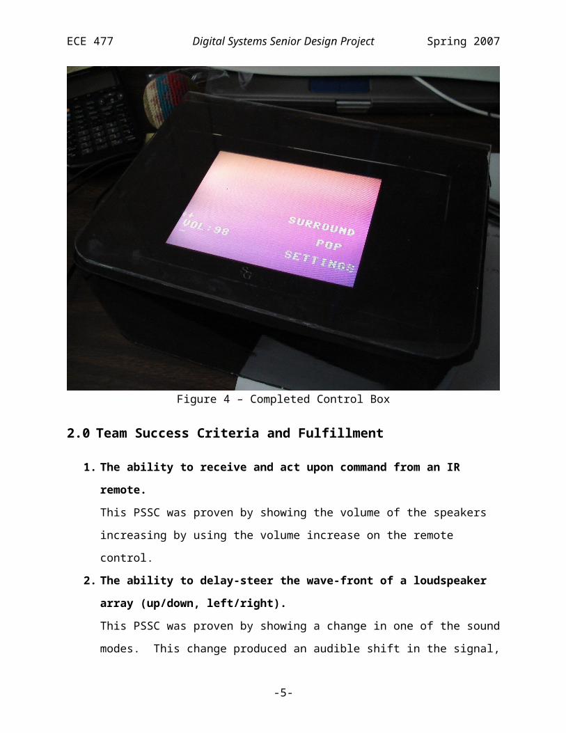
Figure 4 – Completed Control Box
2.0 Team Success Criteria and Fulfillment
1. The ability to receive and act upon command from an IR remote.
This PSSC was proven by showing the volume of the speakers increasing by using the
volume increase on the remote control.
2. The ability to delay-steer the wave-front of a loudspeaker array (up/down,
left/right).
This PSSC was proven by showing a change in one of the sound modes. This change
produced an audible shift in the signal, which is produced by a mix of delay-steering and
amplitude-shading the wave-front.
-4-

ECE 477 Digital Systems Senior Design Project Spring 2007
3. The ability to amplitude-shade the wave-front of a loudspeaker array (adjust
effective array length).
This PSSC was proven by showing a change in one of the sound modes. This change
produced an audible shift in the signal, which is produced by a mix of delay-steering and
amplitude-shading the wave-front.
4. The ability to perform preset equalization.
This PSSC was proven by changing the equalization modes and noting the audible shift
in the equalization.
5. The ability to control loudspeaker settings thorough a user interface.
This PSSC was proven by showing the volume of the speakers increasing by using the
volume increase on the remote control. This was also proven by changing the
equalization and sound modes.
3.0 Constraint Analysis and Component Selection
Each loudspeaker unit will contain a Digital Signal Processor (DSP) that will be used to
create delays, control volume, generate filters, and allow for equalization of the loudspeaker
response. The DSP will interface the CODEC which contains A/D and D/A converters. The
DSP will also control an analog switch to select from two different audio inputs. Once the audio
signal was processed, it would go one audio amplifier per channel, in this case, eight audio
amplifiers. The user interface unit will have a microcontroller used for decoding of the IR
remote, input from touch buttons, output to a built LCD display, and communicate these
commands to each loudspeaker unit.
The loudspeaker system will need to be able to perform real time audio signal processing to
generate delays, each element and total volume, filters, and equalizers. The processing requires
one channel audio input and eight channels audio output. Achieving all of these tasks in real
time would also require a sufficient amount of computational power and memory. Selection of a
DSP, CODEC, and any external memory would need to meet this criterion. The user interface
would not be as demanding computationally. The microcontroller would need to IR decode,
interface buttons, drive a serial to video conversion module, and communicate with the DSP in
each loudspeaker.
-5-

ECE 477 Digital Systems Senior Design Project Spring 2007
Both the DSP and the microcontroller require general purpose I/O to interface external
sources. The DSP will use most of its general I/O (16) in the parallel port to interface with the
SRAM and Flash memory. This general I/O is also used for the select signals to access the
memory. The microcontroller will be interfacing with an infrared receiver module, a graphical
display and set of buttons for the user interface. Buttons will be read with standard I/O (8). The
touch buttons are designed around the Quantum Qtouch design guide using the E240B
evaluation kit [1]. The infrared receiver requires a supply voltage similar to that of the
microcontroller’s in order to produce the proper voltage swing, and requires the microcontroller
to sink 5 mA.
The DSP and the microcontroller require different on-chip peripheral to interface to external
sources. The DSP requires the use of a standard JTEG 10 pin interface for connection to the
programming/BDM module. This interface was designed with the aid of the JTEG interface
reference [2]. Also required are the SPI and digital applications interface (DAI) to interface
directly with the CODEC. The SPI uses 4 pins and the DAI uses 6 pins. The DSP will
communicate with the microcontroller also through the SPI interface requiring 3 pins. The
microcontroller will require 1 A/D pin for the IR remote sensor. Also in order to communicate
with the graphical display the microcontroller will use both its transmit and receive serial
communication pins at a 8N1 9600 baud communication setting through the SCI port, 3 pins.
The video module requires a100 mA at 5V and connects to a television via RCA connector.
The loudspeaker unit also requires additional off-chip peripherals. The DSP will directly
interface to the CODEC, in this case the Analog Devices AD1835A. This contains 2 ADC and 8
DAC channels at 24-bit 96 kHz [3]. This allows each loudspeaker to meet the requirements
specified earlier of at least 1 ADC and 8 DAC channels. Each CODEC output channel will be
connected to 10 W audio power amplifier used to drive each of the eight loudspeakers. The user
interface use a 5.5” LCD TV monitor to display the menu generated by the serial to video
converter.
This system requires the use of many power amplifiers per loudspeaker unit due to the
nature of the delay steering concept. This device is an A.C. powered only and would require
each loudspeaker unit to be powered separately. Eight 10 W power amplifiers are required in
addition to the 55 W subwoofer amplifier used for low frequency generation. Each 10 W
amplifier would consume 1.0A at +12V as calculated from the data sheet for the TPA3001D1
-6-
ECE 477 Digital Systems Senior Design Project Spring 2007
[4]. If all amplifiers were to be at max output it would require 8 A at +12V. Also the
TPA3001D1 is a Class D audio amplifier that would operate at approximately 85% when driving
a 8Ω load [4]. This amplifier uses the printed circuit board to dissipate its heat because it is so
efficient and would not require a heat sink.
The loudspeaker unit was designed to be a small tower loudspeaker that would be relatively
easy for a home audio consumer to move on independently. The overall enclosure would be
constructed of medium density fiberboard (MDF). Each of the eight loudspeakers and the
subwoofer would be individually enclosed to create separate acoustic enclosures to minimize
interference between loudspeakers. The printed circuit board, power supply, and subwoofer
amplifier are in a separate enclosure that has a screen on cover and will be located in the back
each loudspeaker unit. The back of the loudspeaker enclosure would be for audio inputs (RCA)
and an A.C. power input.
The concept of the delay steering loudspeaker is similar to one product on the market. This
product is the Yamaha Digital Sound Projector with an MSRP of $1499 [5]. Our particular
project contains two loudspeaker units and one separate user interface unit that can interface to a
TV for setup too. The goal of our project is to create modern pair of loudspeakers that would
allow the end user superior control of the sound that is economically competitive. The cost of
the major components for a pair of loudspeaker units and one user interface unit are show in
Appendix E.
The main component to the loudspeaker system is the DSP. Once the original design
established, criteria for the DSP was established. The DSP needed to have the power to process
at least 8 channels of audio in real time and easily manipulate these processes in real time.
Examples of functions the DSP would need to be able to control are delay, amplitude, filters, and
equalizers. When looking on the market for an audio based DSP, we narrowed the search to the
TI Aureus™ TMS320DA708 and the Analog Devices SHARC™ ADSP-21262. The both DSP
processor seemed capable of satisfying our specifications. Both are floating point 32 bit DSP
that are available in 144-pin QFP packages targeted at low cost high performance audio
applications. The Analog development environment fit the application required with our project,
where as the TI development environment focused on multi-channel sound sources. The
SHARC™ comes with 4Mbit ROM and 2Mbit SRAM [7] as compared to the Aureus™ which
-7-

ECE 477 Digital Systems Senior Design Project Spring 2007
came with 64kbit ROM and 24kbit SRAM [6]. The SHARC™ was selected based on the
development environment, on chip memory, and fit for our application best.
Now that the DSP was selected, the actual audio interface between the DSP and the analog
audio source needed to be considered. Many different options exist such as separate ADC and
DAC for each channel or one entire CODEC that includes all ADC and DAC. One CODEC
seemed a really good fit, the Analog Devices AD1835A. This contains 2 ADC and 8 DAC
channels at 24-bit 96 kHz [3]. This would be a simpler and more cost effective solution to use
one CODEC in place of 2 ADC and 8 DACs per loudspeaker unit.
The next major component selection was the audio amplifiers used to power each element in
the loudspeaker array. One major consideration is that the amplifier use only a +12V power
supply to decrease power supply cost as compared to having a split power supply and that it
could drive a 8Ω load. First consideration was the ST TDA2006, a Class AB amplifier, which
would draw 2A at +12V requiring a heat sink compared to the TI TPA3001D1, a Class D
amplifier, which is 85% efficient and would draw 1A at +12V not requiring a heat sink [4]. The
TI TPA3001D1 was selected for its high efficiency and lower power consumption.
The final major component to be selected was the microcontroller. Both the Freescale 9S12
family and the Atmel ATmega16 were considered for interfacing with an infrared receiver
module, a graphical display, 8 touch buttons for the user interface, and the DSP engine for each
speaker tower. The 9s12 is a CISC processor and the ATmega16 is a RISC processor. Both
microcontrollers have good development support for C programming and low cost. The Atmel
processor was selected because it is a RISC processor and the familiarity with the C based
development.
The goal of this project is to build a loudspeaker that generates a sound field that can be
steered up/down and left/right through the use of a delay steering and amplitude shading. This
loudspeaker system design consists of a two stereo loudspeaker units controlled by one touch
button user interface unit. In addition to the loudspeaker functions, the user can use an IR
remote to control the entire system and select between two audio input sources. Major design
constraints such as DSP, CODEC, power amplifiers, and microcontroller were carefully
considered and the appropriate components were selected in order to achieve these key aspects of
this digital loudspeaker project.
-8-

ECE 477 Digital Systems Senior Design Project Spring 2007
4.0 Patent Liability Analysis
The Yamaha Digital Sound Projector line (YSP-1, YSP-1000, YSP-1100, and YSP-800)
performs a similar function to our project [13]. Like our project, these speakers are self-
contained units (minus the subwoofer) that use the phased speaker array technique to create
zones of localized sound. In the Yamaha speakers, these “beams” reflect off surfaces of the
room in which the speaker is placed in order to create faux surround sound from a single speaker
system. They also have the capability to produce simple stereo effects and localized regions of
sound.
Another product with similar functionality is the Pioneer PDSP-1, which uses a large
number of speakers to produce a surround sound system in almost exactly the same way as the
Yamaha line [12]. These two products are very similar to one another in many respects and both
products have capability to be controlled by a remote control, as ours will.
Both of these products use Digital Sound Project technology licensed from 1 Ltd, who holds
U.S. Patent No. 7,130,430 on a “phased array sound system,” filed on December 18, 2001 and
granted on October 31, 2006 [11]. The patent describes the technique to use several speakers
with digitally controlled delays in the inputs to each speaker to create localized regions of sound.
The text of the abstract follows:
An array of speakers are fed from a single source of audio frequency sound but each
speaker transmits the sound delayed by an amount which is determined by the distance
between a particular speaker and a selected region in space, so that sound from each
speaker constructively adds at the selected region in space. […] This simple technique
allows audio frequency sound to be heard in only selected regions within the room or
other auditory space. Multiple regions with multiple soundtracks can be created by
simultaneously playing variously delayed soundtracks over each of the speakers in the
array.
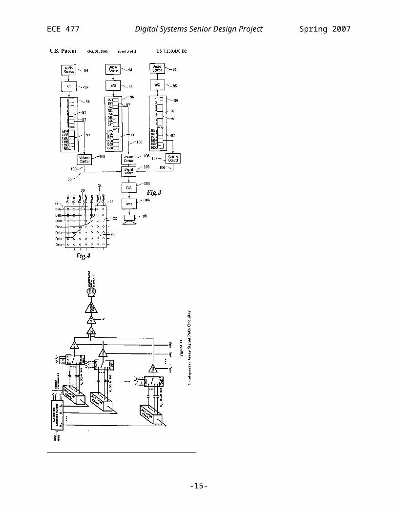
There is significant prior art relating to this patent. In Dr. Meyer’s dissertation, the concepts
and uses of “a digitally controlled, dynamically reconfigurable phased loudspeaker array” are
discussed [9]. Note the similarity between a schematic representation of the patented method
(Fig. 1) and a schematic representation of a reconfigurable array in this thesis (Fig. 2) [11],[9].
Another paper, also by Dr. Meyer, details a multiple beam delay-steered system mounted
horizontally on a ceiling, a specific claim made by the patent as well [10],[11].
-9-

ECE 477 Digital Systems Senior Design Project Spring 2007
Although our product is unlikely to be deemed sufficiently different from the
technology patented by 1 Ltd., a successful court challenge is likely based on the amount of prior
art. The only reason to comply with 1 Ltd.’s patent would be if it proves cheaper to license the
phased array technology from 1 Ltd. that to incur legal costs associated with fighting the patent
in court. The best course of action would be to simply ignore the patent, as 1 Ltd. has no legal
claim to the technology.
Figure 5 – Patent Schematic Figure 6 – Thesis Schematic
5.0 Reliability and Safety Analysis
The failure rate of a MOS device is defined as λp = (C1*πT + C2*πE)*πQ*πL in the
Military Handbook Reliability Prediction of Electronic Equipment [14]. The ADP3336ARMZ
dropout voltage regulator falls under this category. C1 is calculated by the number of transistors
on the chip and is equal to .01 [15]. πT can be taken from the provided table based on the worst
case junction temperature of 150°C and the structure of the chip. πT is equal to 120. C2 is based
on the number of pins the chip has, specifically eight, and its surface-mount design, and is equal
-10-

ECE 477 Digital Systems Senior Design Project Spring 2007
to .0026. The environment may or may not be climate controlled, nor will it necessarily have the
clean conditions described for a “ground benign” climate. Therefore, πE is equal to 2.0 based on
“ground fixed” conditions. πL is equal to 1.0 because the production life, seven years, exceeds
the specified production time of two years. Finally, the device is not military certified and thus
πQ is equal to 10. The TPA3001D1 audio amplifier stability properties are very similar to those
of the illustrated voltage regulator. C1, by transistor count, is also equal to .01 [16]. The worst
case junction temperature is also 150°C so πT is equals 120. The chip has twenty four pins and is
surface mount, so through the lookup table of the military handbook C2 equals .0087. The
environment is the same so πE is equal to 2.0. The production lifetime is approximately five
years, πL is equal to 1.0. This chip is also not military certified and so has a πQ value of 10.
The ADSP-21262 processor is the single most complicated and essential device used
in the product and its failure rate should also be addressed. The processor is a MOS device with
32 or 40 bit capability depending on how it is used [17]. Because the handbook only addresses
processors with up to 32-bit operation, C1 is set to .56. πT, based on its maximum junction
temperature of 125°C and MOS properties, is equal to 3.1. C2 is based on the number of
functional pins the processor has, in this case 144. The table does not have an entry for this
number of pins, so C2 is calculates as C2 = 2.8*10-4*1441.08 = .06. πE is, as with the other parts,
2.0. πL will be set to 2.0: the processor has been produced for over two years, but the specific
packaging variant is new to the point of only being available through sampling. The chip is
MIL-STD-883 certified and, from the military handbook table, πQ is equal to 2.0. Overall, the
statistics available were very applicable to the parts addressed and the results can be considered
accurate, if conservative. A summary of these results is available in the following table:
Component Description MTTF
ADP3336ARM
Z
Dropout Voltage Regulator 1.2052E+01 8.2974E+04
TPA3001D1 Audio Power Amplifier 1.2174E+01 8.2142E+04
ADSP-21262 DSP Processor 7.4240E+00 1.3470E+05
The divided functional blocks of the schematic are the power supply, the Digital Signal
Processor, Audio Output, Audio Input, and the circuit to handle interfacing with the user.
-11-

ECE 477 Digital Systems Senior Design Project Spring 2007
Possible failures are classified as either “high” or “low”, the difference being potential harm to
the user. Critical high failures are to have a λ < 10-9, low failures have a λ value between 10-5
and 10-9. The schematics and failure mode tables are located in Appendix G. Block A, the
power supply circuit, has the hardware to convert the standard alternating current in a given
home to all of the voltage levels required by the audio and processing electronics. Possible
failures include over voltage, no voltage, and noisy voltage. Over voltage has the potential to
create excess heat in the regulator IC which may develop into a threat to the user. No voltage
may be attributed to a shorted circuit, which can also create excess heat and damage components.
It may also be indicative of a destroyed or nonfunctioning component. Noisy voltage could be
caused by a poor connection or damaged or incorrect resistors or capacitors. Block B, the digital
signal processor, raises the possible danger of maximum audio output. If all speakers work in
phase at the maximum gain, it is possible for an output of 110 dB to be produced. This is well
within the range of sound output that can cause permanent hearing damage. Possible high
criticality errors that can cause this include a software error or damage to the processor in block
B, damage to the digital amplifier found in audio output, or a short in audio input. A danger also
exists if the user chooses to turn the audio output to a dangerous volume and is later unable to
change it because of a communication error between the speakers and control box. A scenario
like this may be attributed to a failure of the control box IR receiver, video output, or
communications to the wireless transceiver from any of the processors. It is also notable that
wireless communication failure can be attributed to other devices operating at the 2.4 GHz
frequency, such as wireless video cameras. Other potential errors of less critical significance
include the destruction of a particular component or connection that will cause no audio output.
Obvious possibilities are improper audio inputs, extended use that may cause component failure,
or a poorly soldered component. Circuit or software conditions that may cause operation failures
in the IR sensor or video output will likely be caused by physical damage to the control box
given that, while the circuit is much simpler, the control box is very mobile and thus subject to
accidental impact. While circuit damage and the potential for excessive heat is best prevented
with good design and redundant circuits, errors that could cause dangerous volume output can be
handled with software that will check for communication errors or irregular swings in the audio
signal.
-12-

ECE 477 Digital Systems Senior Design Project Spring 2007
While the Digital Sound Projector can be expected to be in a controlled environment and
contains few components that are prone to failure, it does rely on a large number of duplicate
components in order to achieve high quality directed sound. Some of these parts, including the
ADP3336ARMZ voltage regulator and the TPA3001D1 audio amplifier can be expected to be
running above ambient temperature and will be more error prone. Additionally, the required
processing power necessitates complex processors such as the ADSP-21262 digital signal
processor. While the analysis of these parts revealed a reasonable failure expectation, it is
notable that many of these circuits are duplicated two to eight times, with some failures causing
errors that are difficult to recognize. The FMECA analysis also emphasizes the complexity of
the system and the possibly dangerous effects of component failure, creating a strong importance
on good hardware design and software routines that will catch and prevent dangerous operation.
6.0 Ethical and Environmental Impact Analysis
Following is a discussion of the testing that will be performed, warning labels that should be
attached to the product, cautions to the user contained in the documentation, and any added
safety mechanisms necessary to ensure a safe, high-quality product..
Testing of this product is important not only to verify that the product is safe, but also to
guarantee that it is reliable. All of the tests would be performed in conditions that would
simulate the inside of a house since this is the operating environment for the system. The
temperature range in which the DS3 can operate is 0°C - 50°C (32°F - 122°F) with a humidity
range of 5% - 95%. These environmental conditions are based on the specifications for the
power supply [18]. It will be important to set up rigorous software tests to verify that the product
is up to the desired level of quality. Required testing includes making certain that the delays are
implemented correctly so that the loudspeakers are able to steer sound as intended. The delay for
each element of the loudspeakers will have to be tested independently. Amplitude shading is
another important feature of the product, and therefore will have to be implemented well and
tested thoroughly. Testing the amplitude shading will require verifying that the volume output of
the individual elements can change independent of the other elements. One final software check
is to verify what will happen in the case of a loss of power. The software will need to respond
appropriately to this event, since this event is likely to happen at some point during its lifetime.
In this case, the speaker will reload information from the control box. The control box will have
-13-
ECE 477 Digital Systems Senior Design Project Spring 2007
the previous settings stored, so there should be no change from the previous state once power
resumes.
While there are few warnings that need to be located directly on the loudspeakers, one
example stands out. That is the label that alerts the user that prolonged exposure to high volume
could result in damaged hearing. These speakers are capable of outputting sounds at the 120 dB
level, which is well above the threshold at which hearing damage can occur. This label will be
found on the back of the speaker, located near the cable connections. The only reason the label
will not be placed more on a more visible part of the loudspeakers is to keep up the appearance
of the system. With the label placed near the connections, the user who sets up the speakers will
see it and will know that the loudspeakers should not be used at a high volume for a lengthy
amount of time. In addition to the warning mentioned above, other warnings that the user should
be aware of will be included in the user manual. One such warning is “do not bring liquids near
speakers.” The obvious implications of this include damage to the boards, power supply,
speaker elements, etc. In case the user is not aware of the damage that can be caused by wires
that have been sliced or stripped, a that states “do not operate if wires appear to be damaged”
will be included that the speakers should not be used if the cables are damaged. As noted in the
Yamaha Digital Sound Projector owner’s manual [19], the user should be instructed “do not
open (the casing) due to the risk of electric shock”. This will also be near the warning that there
are “no user changeable parts inside,” alerting the user that there really is no reason to open the
casing anyway. If there were a warranty associated with the product, it would be voided upon
opening the casing, for which there would be another warning.
The last important item to discuss regarding the ethics discussion is safety mechanisms that
should be put into place to prevent the user from harming themselves or the product. No safety
mechanisms are built into the product. As was previously mentioned, the most likely manner in
which this system could harm the user is by prolonged exposure to high volume. It will be up to
the user to follow the guidelines for responsible use of the product.
When it comes to the environmental impact analysis of the DS3, it is easiest to break it down
into different subsystems to study how these parts will affect the environment. The major areas
that will be reviewed are the printed circuit boards (PCBs), power requirements, enclosure
materials, and then the system as a whole. Discussion of each of these subsystems will detail
how these components affect the environment from their manufacture, normal use, and disposal.
-14-

ECE 477 Digital Systems Senior Design Project Spring 2007
The PCBs will be made by 33each.com [20]. According to their website, the boards will
have a “lead free solder finish.” Since lead is harmful to the environment and especially
dangerous to humans, this is an important step towards making a green product. It will also be
important to keep the size of the PCBs as small as possible. There are a lot of components that
need to go into the boards for this project, especially since each of the eight speakers has its own
audio amplifier circuit. Keeping the boards as small as possible will allow for more boards to
be printed in a smaller area, thus reducing waste. Another benefit to keeping the board size
small is to reduce the amount of etchant needed to create the board, thus eliminating some of the
waste that is generated in the board-making process. All of the components will be attached to
the board with lead free solder, which also helps keep the product environmentally friendly.
During the normal use of the product, the PCBs should not create any sort of environmental
impact. When the product has finished its useable life, the PCBs should be sent for recycling.
At a recycling center for PCBs, the metals will be removed from the board before disposal. The
boards are then typically shredded and used for aggregate purposes [21].
The power requirements are another important aspect of the design. The audio amplifiers
were chosen for their efficiency. Class D amplifiers are most advantageous in regards to power
consumption. Each of the audio amplifiers is a Class D power amplifier, and require
approximately 1.3 A [4]. Class AB amplifiers that feature the same output power, require 4 A
[22]. A linear power supply was selected for this project. Each tower will have its own power
supply. The control box will have its own power supply as well, a 12 V wall wart. At the end
of the product lifecycle, the power supplies should be taken to an electronics recycling location
to reclaim parts that could be harmful to the environment.
-15-

ECE 477 Digital Systems Senior Design Project Spring 2007
The wood and paint used for the enclosure of the prototype are important to mention in this
analysis. The wood being used is medium density fiberboard (MDF). According to design-
technology.org [23], there are some potential health risks to using this material. In some cases,
formaldehyde resins are used to hold the pressed board together. These resins have mostly been
phased out, however, and would not be used in production materials. Also according to the
article, the environmental impact of MDF has improved greatly over the years. A lot of the
materials going into MDF are recycled from other processes. The wood should not cause any
harm during the lifecycle of the product and should be recycled after the speaker has run the
course of its lifecycle. The BASF Limco paint that is being used for the prototype is also
harmful to the environment. This paint is typically used to refinish automobiles. It contains four
steps, which are an alkyd enamel, acrylic enamel, urethane, and the base coat. With the proper
personal protective equipment, the paint is not harmful to the person applying it. However, the
toxins that are released from the paint are damaging to the environment. This paint should not
cause any problems during the life of the speakers, but care should be taken when disposing of
them at the end of its life due to the impact of the paint. It is important to note that this paint
would only be used for the prototype, and a more suitable paint would be used for production of
the DS3.
7.0 Packaging Design Considerations
The controlling interface, software, and display need to be capable of displaying and
changing the relatively complicated settings available in such a product, and must also be either
attractive or unobtrusive. Considerations such as total size, individual speaker layout, and
construction materials rely primarily on the need for parts of sufficiently high quality to promote
the unique sound directing features of the project, and to also create a balance between aesthetics
and overall cost.
Two forms of products that implement digitally project able sound are commercially
available today. The first is a set of one or more line arrays, or columns or rows of speakers,
which working together are capable of producing clearer sound in a controlled area with fewer
total speakers [24]. As previously explained, these are typically implemented in medium to large
scale areas and systems. The second form is that of a typically horizontal array of speakers that
use similar but more complex techniques to direct and bounce sound around a room in order to
-16-
ECE 477 Digital Systems Senior Design Project Spring 2007
produce an effect similar to that of surround sound systems. These are available and appropriate
for a range of room sizes that may be found in any given house or apartment, but implement
proprietary and protected algorithms which would make a similar project inadvisable given cost,
time, and complexity constraints.
The packaging for this project can be divided into two sections, the structure and supporting
elements of each tower and the user display elements of the control box. The body of each
speaker tower will be constructed out of medium density fiberboard (MDF). MDF is dense, flat,
stiff, and has no knots or voids [25]. It is very easy to machine, and cut edges will not tear like
plywood. Overall, the substance is very dense, will not shake or rattle if properly mounted, is
well acoustically damped, and is the standard material of choice for speaker enclosures. The
power supply, digital processor, and circuit board will be mounted within the rear base of each
speaker with standoffs and appropriate fasteners to make the electronics stable enough for any
handling of the speakers. The speaker arrangement is chosen for the option to direct sound both
vertically and horizontally. Each individual speaker is mounted into the frame of the tower with
appropriate screws and an insulating adhesive. A subwoofer is included at the base of the tower.
It is also notable that the nature of the speakers and insulating adhesive used, each speaker and
subwoofer will be in its own isolated “chamber”, preventing vibration from interacting between
speakers. 9” is the minimum width of the tower to accommodate the subwoofer and speaker
arrangement, and a tower height set between 3’ and 4’ is an acceptable compromise between
tower size and a minimum height to effectively project sound to specific regions of the room. A
12” square base should provide sufficient room for the subwoofer and included electronics. The
control box will likely be a plastic enclosure with a Lexan plate protecting a 5.5” LCD monitor
and two sets of capacitance touch buttons. Assembly can be completed with relatively simple
tools including a circular and jig saw, drill, soldering iron, and wire cutters and strippers. The
weight of the speaker towers can be estimated at 50 to 60 lbs each. The majority of this will be
for the enclosure, which should weigh roughly 35 lbs. Dense and possibly thick versions of
MDF will be used in order to prevent resonating or shaking. The power supply, subwoofer, and
individual speakers will make up the majority of the remaining weight estimate. As shown in the
bill of materials in Appendix B, the expected cost of each tower is about $510.
The figure in Appendix C illustrates the PCB layout required in each speaker assembly. The
most important factor in placement of the parts and headers is the accessibility of the digital
-17-

ECE 477 Digital Systems Senior Design Project Spring 2007
amplifiers, the DSP communication and programming headers, and the audio input connection.
The DSP and codec chips have the form of a low form quad pack [17], [3] while each of the
eight digital amplifiers are shrink small outline packages. The DSP headers make the SPI and
JTAG pins available. The only restriction on the total board size is that it must fit within the 12”
by 9” space at the base of the tower. If a PCB is required for the control box, the microcontroller
will need a 28 to 40 pin dual in-line package or quad pack depending on the specific model and
package choice [26]. It will require headers to the SPI, reset pin, and serial pins. Connectors for
the infrared module, capacitance touch buttons, and a possible multiplexer will also need to be
included. These consist of standard I/O ports and are variable. The main constraint is that the
board and the ezVID video module, a 2” square board [27], must be able to fit in the box.
By producing a versatile digital sound projector with a range of configuration options to
enable users of all skill levels, this project brings a product previously only available to public or
industrial groups into the consumer market. The design constraints require a set of speaker
towers and control center that are no more obtrusive than a traditional unit, but provide high
quality sound with strong customization of where the output is directed and digitally modified.
At the same time the speakers should be sturdy, reasonably priced, and incorporate aesthetics as
is possible.
8.0 Schematic Design Considerations
The major components of the loudspeaker system are the DSP [17], the memory and the
audio portion of the circuit. The DSP sends delays individually to the eight speaker elements. It
also controls the power shading by controlling the volume of each element. There are two kinds
of memory, SRAM and flash. The SRAM stores the filter coefficients and delay times. The
processor boots from the flash memory into the SRAM [28]. As for the audio portion of the
circuit, an analog switch is connected to the DSP through the parallel port. This switch toggles
between two audio inputs. The signal leads into a 55 W Class AB power amplifier, which leads
to four 8” subwoofers and also into a pre-A/D circuit. This circuit takes the unbalanced signal
from the RCA input, removes any DC offset and creates a differential output, which is required
by the ADC of the codec [3]. The codec converts the signal from analog to digital, passes the
signal to the DSP, and then converts the signal back to analog. The codec has eight DAC
channels [3], which allows for individual signals to be passed to each of the eight speaker
-18-

ECE 477 Digital Systems Senior Design Project Spring 2007
elements. Following the codec are eight identical amplifier modules. Each consists of a post-
D/A circuit, a 10 W Class D power amplifier and finally a 1” full range driver. The post-D/A
mainly serves as a low pass filter that converts the differential signal output from the codec back
to an unbalanced audio signal. The unbalanced audio signal is then passed to a power amplifier,
which drives the speaker element.
The control box consists of a microcontroller, IR sensor, touch button interface and an
interface to an LCD TV. The microcontroller is the heart of the control box. It will take the
signals received by the IR sensor and touch buttons and accordingly output information to the
display. The IR sensor, which receives signals at a frequency of 38 kHz as per the RC5 standard
[29], receives its signal from a universal remote. The IR sensor is connected to the
microcontroller through the ATD port. The user can use the remote to move through the various
speaker settings. To give the user a second method of changing the speaker settings, two sets of
four touch buttons and their control circuits are connected to the microcontroller via GPIO pins.
The touch buttons are used in conjunction with the LDC TV to create a display featuring an
ATM style setup with buttons next to the display options. The LCD TV is a 5.5” display, which
is large enough to display the necessary information in a clear format. A serial to video
converter converts the signal output from the SCI port of the microcontroller to color text and
graphics [30].
The power supply is the other major component of this system. A linear power supply is
incorporated into each of the speaker towers. The supplies are capable of switching between 120
VAC and 230 VAC inputs [18]. Various power levels will be required by the components, +12 V
at 14 A, -12 V at 0.8 A, +5 V at 34 A, -5 V at 0.5 A, +3.3 V at 28 A, and 1.2 V at 500 mA. The
control box will receive its power via a 12 V wall wart.
-19-

ECE 477 Digital Systems Senior Design Project Spring 2007
An ATmega32 microcontroller [26] is at the heart of the control box. General purpose I/O
pins are used to interface with the touch buttons. There touch button kit requires simple interface
between the buttons and the microcontroller. Timer 0 is an 8-bit timer which is used to
determine when to change the data on the display. It checks for differences in the data to be sent
to the screen as the timer overflows a number of times. Timer 1 is a 16-bit timer that is used
with the IR sensor because the timer can automatically use the Input Capture Register (ICR).
The value of timer 1 can be automatically captured when the interrupt high or interrupt low is
triggered so the timer capturing more uniform. The interrupt pin is used in conjunction with
timer 1 to measure pulse lengths from the IR sensor. This pin switches between interrupt high
and interrupt low on the fly. The SPI port is used to program the microcontroller. This port
remains in master mode. Finally, the SCI port communicates with the ezVID serial to video
converter at a 9600 baud rate with 8-bit data packets, and 1 stop bit without parity. This
communication requires both Tx and Rx for timing and command confirmation. The port can
also be used to debug with a terminal application on the PC, but this requires a CMOS to RS232
converter. While debugging, the baud rate can be increased, but not when using the ezVID.
Finally, the interface with each of the loudspeakers is through the SPI port.
The ADSP-21262 DSP is the other major component in the system. Most of this
circuit is similar to the ADSP-21262 EZ-KIT Lite ® Evaluation System [28]. The memory
(SRAM and flash) are interfaced via the parallel port. Also connected to the parallel port is the
analog switch at the beginning of the audio stream. As mentioned before, this switch will
determine which of the audio inputs the system will output. The 25 MHz oscillator, from which
the core frequency of the processor is derived, is connected to the CLKIN pin. As expected, a
JTAG header will be used to program the DSP. The codec communicates with the DSP through
both the Digital Audio Interface (DAI) and through the SPI interface. The internal configuration
registers of the codec are configured using the SPI port [28]. The interface between the towers
and the control box is conducted wirelessly. This module is also connected through the SPI port.
9.0 PCB Layout Design Considerations
The power amplifiers, digital signal processor (DSP), CODEC, power supply components,
and microcontroller all have specific requirements that must taken into account when designing
the PCB in order insure proper operation of the loudspeaker. Both analog and digital circuits are
combined onto one common board. Although on one common board, each section is split into a
-20-

ECE 477 Digital Systems Senior Design Project Spring 2007
separate circuit. Analog circuits are more susceptible to noise than most digital circuits. Digital
circuits often generate noise that can cause problems in analog circuits. Techniques for reducing
ground noise should be addressed through out the layout process. One key to reducing the
ground noise is to decrease inductance in the traces connecting the circuit. This decrease in
inductance can be done by using short, wide traces and by using 45-degree turns instead of 90-
degree turns to decrease transmission reflections [31]. Electromagnetic interference (EMI) is
also another undesirable problem. One possible source of EMI is ground loops. Proper
decoupling capacitor placement, commonly placed as close as possible to the integrated circuit
(IC), and avoidance of creating power and ground loops are two ways to minimize EMI in the
circuit [31]. The board layouts in this project use these techniques and are described in the
following sections.
Another key constraint in this project is proper design the audio amplifier layout. The
TI TPA3001D1, a Class D amplifier, is 75% efficient and does not require a heat sink. The TI
TPA3001D1 thermally connects to the PowerPAD™ located on the bottom IC. The
manufacturer recommends making a copper pour slightly larger than the PowerPAD™ and then
using thermal vias (large vias) to connect to the ground plane on the opposite side of the two
layer board, both at GND potential [32]. This thermally couples the audio amplifier with the
PCB.
The board includes a plated through hole in each corner of the board to create a spot
for the board to mount. Standard 4-40 standoffs are used to connect the PCB to the chassis.
Another key is to leave 50 mils around the outside edge of the board with out copper. This part
of the board gets covered with solder mask and this can help prevent possible problems, such as
component failure due to placement on the edge of the board both in manufacturing.
This project is using the Analog Devices SHARC™ ADSP-21262 DSP in the 144-pin LQFP
package. This PCB design has an analog section and a digital section that are isolated from each
other. The DSP will be located near the center of the digital section of the board to allow access
to all sides of the LQFP package. If the DSP was located in the corner of the board it would be
difficult to route lines to all sides of the package. The external oscillator for the DSP requires
3.3V power with a 0.10µF bypass capacitor and must be physically close to DSP on the board.
The DSP also requires that a specific number of 1000pF, 0.01µF, 0.10µF, and 10.0µF bypass
capacitors be located physically close to both the 3.3V and 1.2V input power pins [28]. These
-21-

ECE 477 Digital Systems Senior Design Project Spring 2007
capacitors are used to decouple noise in the two supply voltages. A 14-pin JTAG header should
also be physically located near the JTAG port on the DSP. The DSP interfaces to both a flash
and SRAM memory through the parallel port and a latch for enables. Both the memory modules
and the latches need to be relatively close the DSP, but are not as critical as the oscillator and
bypass capacitor locations. An additional header is added to allow use of the remaining I/O pins.
Trace widths of 10 to 15 mil should be used for signal routing the near the DSP. The power
traces feeding the DSP should be increased where possible.
The microcontroller selected for this project does not have as stringent layout
constraints as the DSP. The entire user interface is contained on a board independent of the DSP
board. The user interface contains the Atmel ATmega16, in the 44-pin TQFP package,
microcontroller that interfaces to an infrared receiver module, a graphical display, 8 touch
buttons for the user interface, and serially to the DSP in each loudspeaker tower. The ATmega16
requires no external oscillator circuit, because it is integrated into the microcontroller already.
This user interface board contains the ATmega16 centered on a small PCB with bypass
capacitors located next to the power pins and a header close to the serial port used for
programming. A +5V linear regulator in a TO-220 package is used for the power to the board
and located near the edge to allow for the use of an external heat sink if necessary. Similar to the
DSP, trace widths of 10 to 15 mil should be used for signal routing the near the microcontroller
while increasing the size of the power traces where possible.
This system requires the use of many power amplifiers per loudspeaker unit due to the
nature of the delay steering concept. The DSP/Audio Amplifier board requires +12V at 8A, +5V
at 1A, +3.3V at 500mA, and +1.2V at 500mA. Due to the large power requirement, a separate
enclosed power supply is used to provide the +12V. Linear voltage regulators are used to create
the +5.0V, +3.3V and the +1.2V. The +12V line should enter the board through a 16 gauge wire
that feeds directly into the power trace on the board. This power trace needs to be very large to
handle the large DC current needed to supply all eight audio amplifiers. Using a trace width
calculator online, a minimum trace width of 104 mils was recommend for a temperature rise of
10°C from an ambient temperature of 25°C [33]. Each 10 W amplifier would consume 1.0A at
+12V as calculated from the data sheet for the TPA3001D1 [4]. If all amplifiers were to be at
max output it would require 8 A at +12V. This trace needs to be at least 100 mils wide and
larger if possible. Also, four 100uF capacitors are added throughout the +12V trace to assist in
-22-

ECE 477 Digital Systems Senior Design Project Spring 2007
supplying current when all amplifiers are operated at max with an input music signal. The +5V
and the GND signal enter the board through a header. The +5V supply then connects to the
+3.3V voltage regulator and the +1.2V voltage regulator. Trace width of 20 to 50 mils should be
used for power routing each supply voltage on the board. This width is limited by the maximum
trace allowed to exit each pad for a given component. After all components are placed and
routed in layout, a copper pour is added over the entire board. This copper pour is then
connected to the GND, forming a ground plane on the entire board. The ground place is on both
the top and bottom of the board and then stitched together using free vias.
The board is designed to minimize EMI and ground noise in the circuit. Many different
design aspects must be considered developing the printed circuit board (PCB) layout for this
particular project. Trace widths, signal routing, and ground planes are also key elements of the
PCB that must be addressed in order to have a successful design. In order to achieve these key
elements, different design constraints must be in place when designing the PCB.
10.0 Software Design Considerations
The software needed for the DS3 falls into two categories: interfacing and audio
processing. The requirements for each are different, and the software for each needs separate
treatment. Whereas the design considerations for the audio processing are primarily driven by
the need to perform a large amount of computational work sufficiently quickly to avoid a loss of
audio quality, the requirements of the interfacing necessitate a solution capable of providing
control over a wide variety of both internal and external peripheral devices and coordinating their
operation.
The software for the audio processing runs on a SHARC DSP, chosen for its
processing power [36]. The SHARC boasts hardware support for integer, fixed-point, and IEEE
754 32-bit floating point arithmetic, at a maximum sustained calculation rate of 800 MFLOPS
and 400 MMACS when running at 200 MHz. It uses Harvard architecture, dividing its memory
into program and data memory, and it also features a DMA controller that can move arbitrarily
sized blocks of memory to or from any of the peripherals while the processor continues with
other calculations [34] [35]. The SHARC has 1 Mbit of on chip SRAM each for program and
data memories, but must be booted from external Flash. External SRAM is also required by the
Flash programmer application. Note that even though the two memory banks are nominally for
-23-

ECE 477 Digital Systems Senior Design Project Spring 2007
program memory and data memory, either bank can hold code or data. This is very important for
optimization. For example, the equalizer puts the delay line in data memory and the coefficients
in program memory. In this way the DSP can access both sets of data simultaneously, instead of
loading each one individually. This halves the time needed to complete the entire loop.
The software running the DSP is a real-time, interrupt-driven system. When the codec
sends an audio sample to the DSP, it generates an interrupt. The data is equalized using a FIR
filter, and then the equalized output is placed in another delay line. The delay values for each
speaker element determine which index of the delay line is used to output data to the speaker
elements. Outside of the audio interrupt, the DSP monitors the wireless module’s data-ready
line, and clocks data in when it goes high. The DSP will ensure data integrity, requesting a re-
transmit if needed, and then use the data received to adjust the steering of the sound, equalizer,
volume, etc. The coefficients needed to generate the delays and amplitude shading used for
steering will be stored in look up tables loaded into memory via the DMA. If any calculations
are needed (such as for an equalizer) this will be performed in the main loop outside of any
interrupts. The loading of new delays and generation of the new coefficients is not time critical,
as there is a considerable amount of CPU time available until the end user would notice any lag.
To perform its function, the DSP software makes use of many of the on-chip peripherals.
The codec chip being used for AD and DA uses three serial ports (SPORT0 through SPORT2)
and the SPI port. The wireless connection between the microcontroller and DSP also interfaces
through the SPI port. Flash memory will interface through the parallel port (though SPI Flash
has not been ruled out entirely). The DSP also has provision for attaching a JTEG header to the
chip, which allows us to program and debug using the same tools as are available for the
development board as well as giving us a convenient method for in-circuit programming the
Flash.
The Atmel processor running the interfacing code will need a wide variety of peripherals
[37]. The SCI interface is used to interface to the TV/LCD display and SPI port to send and
receive data via the wireless module. Additionally general purpose I/O pins are needed to read
the status of the buttons and an external IRQ is needed to correctly decode data from the IR
receiver.
The interface software is a command driven and polled system. The IR receiver needs to
generate an interrupt for accurate timing (possibly in conjunction with the timer module), but
-24-

ECE 477 Digital Systems Senior Design Project Spring 2007
when a whole command is received, a flag will be set that will be processed in the main loop.
The buttons can be polled periodically in a similar fashion. These are the only inputs that can
cause the system to change state, and the system is not time-critical. The interface software also
needs to have the capability to retransmit lost packets. The system can be programmed in circuit
using the SPI interface, and external components (aside from maybe an external oscillator) are
not required.
The interface software sits in an idle loop polling flags. When the IR module detects a
change in the signal, an interrupt is generated. The length of this pulse is timed to detect a one or
zero in the command sequence. When enough bits are detected for a command to be recognized,
the corresponding flag is set. When a flag indicating that a either a button on the control box has
been pressed or an IR command has been received is set, the user interface is updated
accordingly, and if needed, data is sent to the speaker units to indicate the change in settings.
If the speaker box transmits data, the system will enter an interrupt where it will
process the data received, triggered by an external IRQ connected to the wireless module. The
only data received by the speaker should be acknowledge or resend requests. In the case of the
former, the next set of data in the buffer will be sent, while in the case of the latter, the last data
will be resent.
11.0 Version 2 Changes
If going through this design effort again, there a few changes would be made. This first
change would be use a touch screen interface for the control box instead of the video screen and
touch buttons with the serial to video module. After ordering the parts for the touch button and
video screen, a touch screen was found which would have been easier to implement and cheaper
than the combination of parts that was purchased.
The DSP would also change during the second version. The new selection would be
Analog Device’s Sigma DSP (AD1859) instead of their SHARC DSP (ADSP-21262). The
Sigma incorporates the codec into the chip, creating a “digital audio playback subsystem on a
single chip.”[38]
-25-

ECE 477 Digital Systems Senior Design Project Spring 2007
12.0 Summary and Conclusions
The Digital Steerable Sound System (DS3) is a loudspeaker system that can be used to
point sound in any direction. The idea behind this concept is that the speakers can be placed in
non-ideal room settings. Effectively, the sound is independent of the acoustics of the room and
can be limited to only the intended users. The typical customer for this type of system is one that
would purchase high-end audio equipment for use in the home. This system would work well in
the average living room or even in an in-home movie theater. As was previously mentioned, the
goal of this product was to develop a loudspeaker system that could direct sound based on the
user’s input. This steering is possible up and down as well as left and right. One of the other
features incorporated into the project is a control interface for the user to step through the
speaker settings. This unit is separate from the towers and communicates with them wirelessly.
The user can also adjust settings via an infrared remote control. Another feature of the system is
to amplitude shade the wave-front. This is done by altering the volume of the individual
woofers. The final feature was also mentioned previously. This feature consists of preset
equalization modes from which the user may select how they would like audio to be output.
Throughout this project, many new skills and concepts have been learned. Of course
further audio knowledge was picked up by everyone on the team. By figuring out how to change
the different sound modes via delay-steering and amplitude-shading the team learned a lot about
audio technology. The team also learned quite a bit about DSP’s and how to incorporate them
into a design. Prior to this course no one on the team had any experience with them, but now the
team is able to successfully use one to control the output of the speakers. Finally, this project
taught the team a lot about working together to bring about the final product. The whole team
realized early on that it was important to be working on the project extensively throughout the
semester. By setting goals and keeping them (for the most part), the team was able to prove the
concept behind this large project in only sixteen weeks.
13.0 References
[1] Quantum Research Group. (2005) Secrets of Success Qtouch Design. [online]. Available: http://www.qprox.com/downloads/appnotes/an-kd02_103-touch_secrets.pdf
[2] Analog Devices. (2004) Analog Devices JTEG Emulation Technical Reference. [online]. Available:
-26-
ECE 477 Digital Systems Senior Design Project Spring 2007
http://www.analog.com/UploadedFiles/Application_Notes/4280679728866EE068v09.pdf
[3] Analog Devices (2003 Dec.) AD1835A Data Sheet. Rev. A. [online] Available: http://www.analog.com/UploadedFiles/Data_Sheets/AD1835A.pdf
[4] Texas Instruments. (2002) TPA3001D1 Data Sheet. [online] Available: http://focus.ti.com/lit/ds/symlink/tpa3001d1.pdf
[5] Yamaha Electronics Corporation. (2006) YSP-1100 Brochure. [online]. Available: http://www.yamaha.com/yec/ysp1/resources/ysp_bro_06.pdf
[6] Texas Instruments. (2005) Aureus™ TMS320DA708 Features. [online]. Available: http://focus.ti.com/lit/ml/sprt377/sprt377.pdf
[7] Analog Devices. (2003) ADSP-21262 Product Highlights. [online]. Available: http://www.analog.com/UploadedFiles/Product_Highlights/23374750121262_final__0_.pdf
[8] ST. (2003) “TDA2006 Data Sheet,” [online]. Available: http://www.st.com/stonline/products/literature/ds/1452.pdf
[9] Meyer, D.G., “A Multi-Microprocessor Controlled Dynamically Reconfigurable Phased Loudspeaker Array for Sound Reinforcement Applications,” Ph.D. dissertation, Dept. Elec. Eng., Purdue University, West Lafayette, IN, 1981.
[10] Meyer, D.G., “Multiple-Beam, Electronically Steered Line-Source Arrays for Sound-Reinforcement Applications,” Journal of the Audio Engineering Society, Vol. 38, No. 4, pp. 237-249, Apr. 1990.
[11] Milsap, J. P., “Phased array sound system,” U.S. Patent no. 7130430, Oct. 2006.
[12] Pioneer Europe. PDSP-1 Loudspeakers – Pioneer Product Archive. [online]. Available: http://www.pioneer.co.uk/uk/products/archive/PDSP-1/index.html
[13] Yamaha. (2006). YAMAHA :: YSP-1. [online]. Available: http://www.yamaha.com/yec/ysp1/idx_products.htm
[14] Department of Defense. (1990). Jan. Military Handbook Reliablity Prediction of Electronic Equipment. [online]. Available: http://cobweb.ecn.purdue.edu/~dsml/ece477/Homework/Fall2006/Mil-Hdbk-217F.pdf
[15] Analog Devices. (2000). AD3336 Datasheet. [online] Available: http://www.analog.com/UploadedFiles/Data_Sheets/ADP3336.pdf
-27-

ECE 477 Digital Systems Senior Design Project Spring 2007
[16] Texas Instruments (2006 Jul.). 20-W Class-D Audio Power Amplifier. [online]. Available: http://www.ti.com/lit/gpn/tpa3001d1.pdf
[17] Analog Devices. (2005 Oct.) ADSP-21262 Data Sheet. Rev. B. [online] Available: http://www.analog.com/UploadedFiles/Data_Sheets/ADSP-21262.pdf
[18] Power-One. Linear Power Supplies Data Sheet. [online], Available: http://www.power-one.com/resources/products/datasheet/lin.pdf
[19] Yamaha Corporation. YSP-1000: Digital Sound Projector Owner’s Manual. [online]. Available: http://www2.yamaha.co.jp/manual/pdf/av/english/dsp/YSP-1000e.pdf
[20] Advanced Circuits. Circuit board equipment for testing and fabrication of pcbs. [online], Available: http://www.33each.com/
[21] The A to Z of Materials. Computer and Electronic Scrap Recycling”. [online]. Available: http://www.azom.com/details.asp?ArticleID=1767
[22] National Semiconductor. LM1875. [online], Available: http://www.national.com/ds/LM/LM1875.pdf
[23] Design Technology Department. Medium Density Fibreboard. [online], Available: http://www.design-technology.org/mdf.htm
[24] Audio Engineering Society, (2001 Nov. 30). Directional Radiation Characteristics of Articulating Line Array Loudspeaker Systems. [online]. [online]. Available: http://www.alfordmedia.com/linearray/AES_DirRadiation.pdf
[25] Wikipedia, (2007 Jan. 23). Medium Density Fibreboard, [online]. Available: http://en.wikipedia.org/wiki/Medium_density_fiberboard
[26] Atmel Corporation. (2006 Oct.) ATmega32(L): Summary. Rev. J. [online]. Available: http://www.atmel.com/dyn/resources/prod_documents/2503S.pdf
[27] Multilabs. (2004). ezVID Serial Video Module. [online]. Available: http://www.jameco.com/Jameco/Products/ProdDS/355856MAN.pdf
[28] Analog Devices. (2006 Aug.). ADSP-21262 EZ-KIT Lite® Evaluation System Manual. Rev 3.0. [online]. Available: http://www.analog.com/UploadedFiles/Associated_Docs/488380715ADSP_21262_EZ_KIT_Lite_Manual_Rev._3.0.pdf
[29] Spark Fun Electronics. (2004 Mar.). TRF-2.4G Reference Guide. Rev 1.01. [online]. Available: http://www.sparkfun.com/datasheets/RF/RF-24G.pdf
-28-

ECE 477 Digital Systems Senior Design Project Spring 2007
[30] MULTILABS. (2004). ezVID User Manual. Rev. B.[online]Available: http://www.multilabs.net/Files/ezVID_User_Manual_Rev_B.pdf
[31] Freescale. (1995) Freescale Semiconductor Application Note AN1259. Available: http://www.freescale.com/files/microcontrollers/doc/app_note/AN1259.pdf
[32] Texas Instruments. (2006) PowerPAD™ Layout Guidelines SLOA120. Available: http://focus.ti.com/lit/an/sloa120/sloa120.pdf
[33] Advanced Circuits. (2007) Online Trace Width Calculator. Available: http://www.circuitcalculator.com/4pcb/trace_width_calculator.php
[34] Analog Devices, “ADSP-2126x SHARC DSP: Core Manual,” [Datasheet], Analog Devices, 2004.
[35] Analog Devices, “ADSP-2126x SHARC Processor: Peripherals Manual,” [Datasheet], Analog Devices, 2005.
[36] Analog Devices, “SHARC Embedded Processor: ADSP-21262,” [Datasheet], Analog Devices, 2005.
[37] Atmel, “ATmega64: 8-bit AVR Microcontroller with 65K Bytes In-System Programmable Flash,” [Datasheet], Atmel, 2006.
[38] P. Predella. Single-Chip Digital Stereo Subsystem. Analog Dialogue. [online]. Available: http://www.analog.com/library/analogDialogue/archives/30-2/subsystem.html
-29-
ECE 477 Digital Systems Senior Design Project Spring 2007
Appendix A: Individual Contributions
A.1 Contributions of Joe Land:
For over 12 years now, I have been fascinated by loudspeaker design. As I progressed
through my electrical engineering courses, I had always wanted to develop a modern loudspeaker
system for my Senior Design Project. After reading about line arrays and building two different
pairs of line array loudspeakers, I thought I would design a new system based on traditional
loudspeaker styling, with a new twist. This was to use an eight element loudspeaker array and try
to recreate the effects of a larger line array. This design project focused on building a
loudspeaker that generates a sound field that can be steered up/down and left/right through the
use of a delay steering and amplitude shading. This loudspeaker system design uses two stereo
loudspeaker units controlled by one touch button user interface unit. After coming up with the
initial design, I convinced my three team members that this would be a fantastic Senior Design
Project.
During the project, I contributed by designing and developing all of the hardware
systems, designing and building the physical enclosures for the loudspeakers and control units,
designing and simulating the acoustical aspect of the loudspeaker system, and all wiring involved
with the construction of the loudspeakers. After researching different types of digital signal
processors available on the market, I selected the Analog Devices SHARC™ processor do to its
development environment. Once we found the development kit in lab, I started looking into the
different possibilities for audio power amplifiers that we could use for the project. After
considering a Class AB and Class D amplifiers, I selected a TI Class D amplifier because of its
low external parts count, high efficiency, and its power output. Next after using most of the
same design as the development kit, I added in a new power regulation design and the audio
amplifiers to the entire system. Once the schematic was developed with Elizabeth, I began
assignment of component footprints and started the design of the PCB layout. This was a very
challenging design because of the mixed signal nature of the board. I chose to make a two
separate ground planes and spent 76 hours creating the board design.
Over my spring break, I designed and built the loudspeaker enclosures. This was fun
to watch the design finally come to life. I have developed a construction process for loudspeaker
enclosures and painting over the past 4 years that I applied to the construction of this loudspeaker
A-1

ECE 477 Digital Systems Senior Design Project Spring 2007
system. After we received the PCB, I worked with Elizabeth to populate the PCB with all of its
components. I troubleshoot a few problems with the board design and modified the design for
the second PCB. During the stuffing of the board, I soldered 98% of the components onto both
boards. Once the PCB was testing and functioning properly, I loaded into the rear of the
loudspeaker enclosures. At this point I had wired all of the AC and other circuits needed to
make the loudspeaker function properly.
Once the loudspeaker was working with the control box, Ben and I began to tweak the
loudspeaker settings. I designed all of the sound modes that are currently implemented in the
loudspeaker system with a spreadsheet I developed to predict the steering of the sound. This was
a tremendous project that I spent over 377 hours during the semester. I was excited to see this
loudspeaker system working after all of the effort put into the project. It was also exciting to see
an idea I had on paper for a long time final become a fully functional product.
A.2 Contributions of Ben Fogle:
My largest contribution was in implementing DSP related functionality, most notably the
software. In addition to writing all the audio processing and peripheral interface software, I also
wrote several utility programs, including a Flash memory programmer and a Flash memory test.
All of the code was placed in a CVS repository he set up for easy retrieval of older versions and
convenient remote access.
The software had to interface with the codec using a combination of the SPI and three
I2C interfaces, interface with the wireless using the SPI and three GPIO pins, and interface with
the memory using a parallel bus. For audio processing, the software had to implement cascaded
biquad filters to adjust the speaker response and apply equalizers to the sound output. It also had
to implement a delay line and amplitude shading for steering the sound. All of these functions
had to be done sufficiently quickly or in such a way as to avoid degradation of the sampled audio
stream. A large amount of time was spent getting the wireless module to work correctly. The
wireless module has very slow timing requirements compared to the DSP and a function to
implement long waits (~100 ms maximum) while still allowing audio processing interrupts to
proceed without losing accuracy was developed. I also devised a communication protocol
between the control box and the speakers allowing for separate control of each speaker and
verification of data integrity.
A-2

ECE 477 Digital Systems Senior Design Project Spring 2007
The Flash programmer had to take the output of the compiler, linker, and loader and
program it into the Flash along with data describing the equalizers, delays, and amplitude
shading. All of the data to be programmed needed to be stored in external SRAM, which
required me to define memory segments for each block of data to be programmed, because the
linker cannot correctly calculate the address of external memory unless it is at the beginning of a
segment (whose address is manually specified).
I was also responsible for learning the development tools for the DSP and its architecture.
It was important to learn how the compiler used the super-Harvard architecture of the DSP to
produce optimized code in order to make code execute fast enough to keep up with the sample
rate. Optimization related extensions to the language were also needed. Although the software
was written in C++, I had to learn a small amount of SHARC assembly to understand some of
the assembly language examples provided by Analog Devices. I also needed to understand how
memory organization was influenced by extensions to the C/C++ language, and how other
extensions and built-in functions allowed me to work with non-memory-mapped system
registers. The output of the loader, a utility that produces a file suitable for loading from Flash,
also needed to be learned, as the Flash programmer needed some special settings to produce a
file suitable for use with my custom programmer. A feature that appears to be unique to
Analog’s DSPs is the signal routing unit, which routes functional blocks to physical pins at run-
time. The signal routing unit took some time to understand and make functional.
I was responsible for the selection of the memory chips used in the final design, as we
were unable to obtain the exact part used in the development kit. The different Flash memory
had a slightly different programming interface which necessitated further modifying the Flash
programmer. I also soldered components onto the final PCB and buddy board and helped add fly
wires to repair the PCB. I also helped troubleshoot the PCB.
A.3 Contributions of James O’Carroll:
As the final member of the group, added on the first day of class, my first task was to
make clear my specific skills and abilities to the rest of the group in relation to what I had
learned about the project. Having explained that I was specifically capable with the Atmel series
of microcontrollers and could personally handle any software aspects of the project relating to
communicating with peripherals, the team eventually decided upon a method for a user to change
A-3
ECE 477 Digital Systems Senior Design Project Spring 2007
and view the numerous setting possibilities the speakers would have: the control box. The
control box has been my primary responsibility for the duration of the class, and for the greater
part of the class it was largely independent of progress on the speaker towers. In addition to this
I made an initial form of the team website and later maintained and added content to the newer
website that Joe developed. Finally, I contributed as required to team presentations, reports, and
the technical challenges of communication between the SHARC and Atmel processors.
In the earliest part of the semester, I focused on portions of the control box that were not
subject to change, specifically communication with a standard infrared remote control and
communication with the speaker tower. I personally selected a standard infrared receiver module
and the Philips RC5 IR communication scheme and over the first half of the semester developed
a robust algorithm for receiving and processing the received signals. To communicate with the
speaker tower, I proposed using the TRF 2.4G transceiver module. It is worth expressing here
that this module has a communication scheme that is fairly complex, has moderately poor
documentation, and is very difficult to debug. Hence, I spent a good deal of time attempting to
make successful transmissions between two modules. When I eventually succeeded I expanded
the algorithms to the communication scheme proposed by Ben. When communicating between
the SHARC and TRF proved difficult, I developed a microcontroller program to emulate the
TRF and learn firsthand what the specific problems were. Finally, the team eventually decided
to use an ezVID video module and embedded television to display data to the user. I had
initially written a very complex function involving variable input arguments and dynamically
allocated space in order to introduce a layer of abstraction into the fairly specific requirements of
the ezVID, but had to discard it in favor of a less capable program in order to allow for saving
long term variables in flash memory. The better part of my time in the final weeks of the
class were spent bringing the independent software functions together into one package, testing
communications between the two processors before and after the decision to make
communications only one way, and some changes to the menu system to accommodate an
additional set of touch buttons that were to be added. My main administrative task was to
maintain the group website, adding links to homework assignments, documents, pictures, and so
on.
A.4 Contributions of Elizabeth Strehlow:
A-4

ECE 477 Digital Systems Senior Design Project Spring 2007
I was responsible for various tasks throughout the duration of this project. Some of
these tasks include working on the schematics and PCB layout, helping populate the board,
creating the final video, and helping with some of the more administrative tasks such as
documentation.
At the start of the project the team was building off of Analog Device’s EZ-KIT Lite
development board. My task was to recreate the portions of their board that we would be
replicating for our design. I also helped set up some of the footprints for the resistors and
capacitors. For my part with the PCB layout, I assisted the team leader in laying out the
amplifiers along one side of the board. The amplifiers were laid out based on the advice from
Texas Instruments. The last part I had with the schematics and PCB layout was to work on the
parts list for ordering the parts. Since there were almost 600 components on each board it was
important to group the parts by their like components to make ordering easier.
One of the challenges associated with this project was the large number of parts.
During the time that the boards were being populated, I helped keep the parts organized and
assisted the team leader to populate the boards. My role in this was mostly to make sure he had
the correct parts in hand and help him determine where to place each part. I was also there to
look up datasheets to ensure that the parts were being placed in the correct orientation. While the
first board was being populated, I also helped keep track of changes we wanted to make to the
PCB design before sending out for the second board and then helped the team leader implement
the necessary changes.
Since I own a video camera, I took on the responsibility of creating the video to
demonstrate the project. I used video editing software that was on my computer. Unfortunately
with the idea of the project it was difficult to prove the PSSC’s with the microphone built into
the camera.
While I was not the team leader on this project, I did help him with organization and
keeping track of what was going on. Starting at the beginning of the semester I took notes of
each of our team meetings to ensure that everyone was on the same track. I also wrote up the
first few homework assignments based on our discussion from those first few meetings. From
that point on I was there to help remind the team when assignments were due and who was
responsible for each of them. While everyone contributed to the mid-semester design review, I
A-5
ECE 477 Digital Systems Senior Design Project Spring 2007
put together the actual presentation and made sure the team had the appropriate documentation
ready for the presentation itself. I also took on the role of organizing the final documentation for
the project. This task involved creating the first draft of the user manual and senior design report
as well as compiling the edited homework assignments from the rest of the team members.
A-6
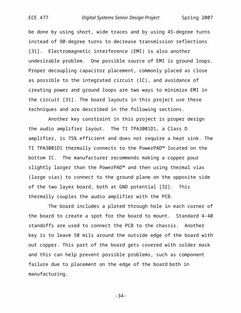
ECE 477 Digital Systems Senior Design Project Spring 2007
Appendix B: Packaging
B-1
55W Subwoofer Amplifier
49”
9”
12”
Figure 7 – Active Loudspeaker Unit
2” Loudspeaker
8” Subwoofers
Array of 8 Loudspeakers
Enclosure (MDF)
Small Sealed Chamber for
each 2” Loudspeaker
Sealed Chamber for
each 8” Subwoofer
+12V Power Supply
DSP and 8 Channel Amplifier Board
Dimensioned Drawing Cut-away Drawing
Front View Side View Front View Side View
Flared Port
BASSIS Bass Equalization
Figure 8 – Control/User Interface
Main Menu
Normal
FlatSettings
Input
-+
8.0”
6.0”
3.0”
Main Menu
Normal
FlatSettings
Input
-+
Capacitance Touch Buttons
5.5” LCD TV Monitor
Lexan® Cover
MDF Case
Standoff
Prototype Board for
User Interface
Touch Button Sensor
Video Out (TV)
IR Sensor

ECE 477 Digital Systems Senior Design Project Spring 2007
Appendix C: Schematic
C-1
Figu
re 9
- Po
wer
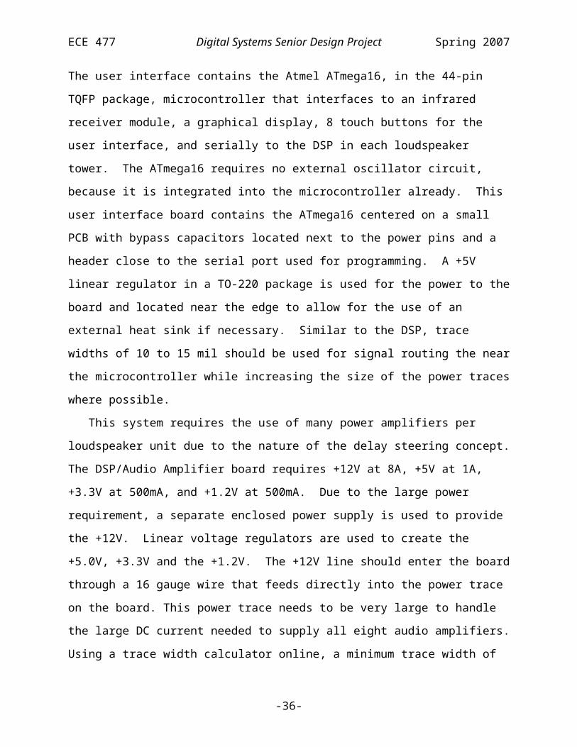
ECE 477 Digital Systems Senior Design Project Spring 2007
C-2
Figu
re 1
0 –
DSP
/Res
et
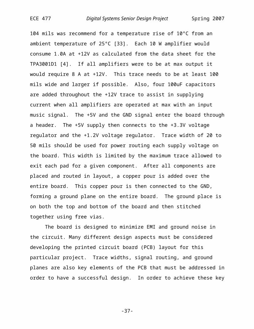
ECE 477 Digital Systems Senior Design Project Spring 2007
C-3
Figu
re 1
1 - M
emor
y

ECE 477 Digital Systems Senior Design Project Spring 2007
C-4
Figu
re 1
2 - A
udio
Inpu
t

ECE 477 Digital Systems Senior Design Project Spring 2007
C-5
Figu
re 1
3 - A
nalo
g A
udio

ECE 477 Digital Systems Senior Design Project Spring 2007
C-6
Figu
re 1
4 - A
udio
Out
put 1

ECE 477 Digital Systems Senior Design Project Spring 2007
C-7
Figu
re 1
5 - A
udio
Out
put 2

ECE 477 Digital Systems Senior Design Project Spring 2007
C-8
Figu
re 1
6 - A
udio
Out
put 3

ECE 477 Digital Systems Senior Design Project Spring 2007
C-9
Figu
re 1
7 - A
udio
Out
put 4

ECE 477 Digital Systems Senior Design Project Spring 2007
Appendix D: PCB Layout Top and Bottom Copper
Figure 18 – Top Copper Pour (First Board)
D-1

ECE 477 Digital Systems Senior Design Project Spring 2007
Figure 19 –Bottom Copper Pour (First Board)
D-2

ECE 477 Digital Systems Senior Design Project Spring 2007
Figure 20 – Top Copper Pour (Second Board)
D-3
ECE 477 Digital Systems Senior Design Project Spring 2007
Figure 21 –Bottom Copper Pour (Second Board)
D-4

ECE 477 Digital Systems Senior Design Project Spring 2007
Appendix E: Parts List Spreadsheet
Vendor Manufacturer Part Number DescriptionPrice Each
Quantity
Total Cost
Mouser AVX 08051C103KAT2A
Multilayer Ceramic Chip Capacitor (MLCC) 0805 0.01uF 100volts X7R 10% 0.17 12 2.04
Mouser MurataGRM21BR61A106KE19L
High Capacitance SMD Ceramic Chip Capacitors 0805 10uF 10volts X5R 10% 0.48 7 3.36
Mouser AVX 08055C221KAT2A
Multilayer Ceramic Chip Capacitor (MLCC) 0805 220pF 50volts X7R 10% 0.17 8 1.36
Mouser KemetC0805C104K5RACTU
0805 SMD Ceramic Chip Capacitors 50volts 0.1uF X7R 10% 0.06 31 1.86
Mouser KemetC0805C104K5RACTU
0805 SMD Ceramic Chip Capacitors 50volts 0.1uF X7R 10% 0.06 1 0.06
Mouser AVX TPSD476K016R0150
SMD Tantalum Capacitors 47uF 16V 10% L ESR 2.34 1 2.34
Mouser AVX 08055A471JAT2A
Multilayer Ceramic Chip Capacitor (MLCC) 0805 470pF 50volts C0G 5% 0.17 1 0.17
Mouser TDK Corp C1608C0G1H680J
0603 Ceramic Chip Capacitors 0603 68pF 50volts C0G 5% 0.08 1 0.08
Digi-Key Panasonic-ECG EEE-0JA470WRCAP ELECT 47UF 6.3V VS SMD 0.16 1 0.16
Mouser AVX TAJB225K035R
SMD Tantalum Capacitors 35V 2.2UF 10% 0.53 1 0.53
Digi-Key AVX 08055A331JAT2ACAP CERM 330PF 5% 50V NP0 0805 0.11 8 0.88
Mouser Kemet C0805C681J5GACTU
0805 SMD Ceramic Chip Capacitors 50volts 680pF C0G 5% 0.30 12 3.60
Mouser MurataGRM2165C2A101JA01D
0805 SMD Monolithic Ceramic Chips 0805 100pF 100volts C0G 5% 0.10 4 0.40
Mouser AVX 12061A101JAT2A
1206/1812 SMD Ceramic Capacitors 1206 100pF 100volts C0G 5% 0.25 14 3.50
Mouser AVX 12061A221JAT2A
1206/1812 SMD Ceramic Capacitors 1206 220pF 100volts C0G 5% 0.25 9 2.25
Digi-Key AVX 12065A222JAT2ACAP CERM 2200PF 5% 50V NP0 1206 0.59 8 4.69
Digi-Key Panasonic-ECG EEE-1CA100SRCAP ELECT 10UF 16V VS SMD 0.14 12 1.73
Digi-Key Panasonic-ECG ECJ-2VF1C474Z CAP .47UF 16V 0.06 16 0.90
E-1
ECE 477 Digital Systems Senior Design Project Spring 2007
CERAMIC Y5V 0805
E-2

ECE 477 Digital Systems Senior Design Project Spring 2007
Vendor Manufacturer Part Number DescriptionPrice Each
Quantity
Total Cost
Mouser AVX 08055C102JAT2A
Multilayer Ceramic Chip Capacitor (MLCC) 0805 1000pF 25volts X7R 5% 0.37 16 5.92
Mouser AVX LD02YC102KAB2A
MLCC Tin/Lead Termination "B" 16volts 1000pF 10% 0402 X7R 0.27 20 5.40
Mouser NTE SMC1206J121
replacement Capacitors 1206 120pF 50volts NP0 5% 0.14 2 0.28
Digi-Key AVX 08055A102JAT2ACAP CERM 1000PF 5% 50V NP0 0805 0.22 4 0.88
Mouser Kemet C0805C300J1GACTU
: 0805 SMD Ceramic Chip Capacitors 100volts 30pF C0G 5% 0.28 1 0.28
Mouser TDK Corp C2012X7R1E105K
High Capacitance SMD Ceramic Chip Capacitors 0805 1uF 25volts X7R 10% 0.35 55 19.25
Mouser AVX 080560106KAT2A
0805 SMD Ceramic Capacitors 0805 10uF 6.3volts X5R 10% 1.10 2 2.20
Mouser AVX 1206YD106KAT2A
Multilayer Ceramic Chip Capacitor (MLCC) 1206 10uF 16volts X5R 10% 2.40 2 4.80
Digi-Key Panasonic-ECG ECJ-2VF1C224ZCAP .22UF 16V CERAMIC Y5V 0805 0.06 16 0.93
Mouser Kemet T491D106K035AT
SMD Tantalum Chip Capacitors 35V 10uF 10% 0.48 8 3.84
JamecoJameco Valuepro 100UF/16V 6X7
CAP,RADIAL,MINI,7MM,100uF16V 0.15 5 0.75
Digi-Key Panasonic-SSG LN1261CTRLED RED GW-TYPE SMD NO HDR/TRLR 0.33 1 0.33
Digi-KeyInfineon Technologies BAS16INCT-ND
DIODE SWITCHING 85V SOT-23 0.16 1 0.16
Digi-KeyVishay/General Semiconductor SL22-E3/52T
DIODE SCHOTTKY 2A 20V SMB 0.43 1 0.43
Digi-KeyMicro Commercial Co. 1N4002-TP
RECTIFIER 1A 100V DO-41 0.04 2 0.09
Digi-Key Diodes Inc B130-13DIODE SCHOTTKY 30V 1A SMA 0.58 16 9.28
Digi-Key TDK Corp 445-2014-1-NDINDUCTOR SHIELD PWR 10UH 7045 1.31 1 1.31
Digi-Key TDK Corp 445-2029-1-NDINDUCTOR SHIELD PWR 6.8UH 7045 1.31 1 1.31
Digi-Key Steward 240-2390-1-NDFERRITE CHIP POWER 600 OHM SMD 0.11 4 0.45
Mouser Fair-Rite 2512067007Y3EMI Shield Beads 1206 Z=70@100MHz 0.30 16 4.80
Digi-KeySTMicroelectronics 497-2539-5-ND
TRANS NPN DARL 60V 5A TO-220 0.74 1 0.74
E-3

ECE 477 Digital Systems Senior Design Project Spring 2007
Vendor Manufacturer Part Number DescriptionPrice Each
Quantity
Total Cost
Mouser Vishay/DaleCRCW080510R0FKEA
0805 Thick Film Chip Resistors 1/8watt 10ohms 1% 0.05 1 0.05
Digi-Key Vishay/DaleCRCW080533R0JNEA
RES 33 OHM 1/8W 5% 0805 SMD 0.04 2 0.08
Digi-Key Vishay/DaleCRCW08054K70JNEA
RES 4.7K OHM 1/8W 5% 0805 SMD 0.04 1 0.04
Mouser Xicon 292-210K-RC
1/10W 1% 0805 Chip Resistors 1/10WATT 210KOHMS 0.04 2 0.08
Mouser Vishay/DaleCRCW080564K9FKEA
0805 Thick Film Chip Resistors 1/8watt 64.9Kohms 1% 0.05 2 0.10
Mouser KOA Speer RK73H1JTTD2492F
: 0603 SMD Thick Film Chip Resistors 1/10watts 24.9Kohms 0.08 1 0.08
Digi-KeyYageo Corporation RC0603FR-0780K6L
RES 80.6K OHM 1/10W 1% 0603 SMD 0.08 1 0.08
Mouser KOA Speer RK73H2ATTD2553F
0805 SMD Thick Film Chip Resistors 1/8watts 255Kohms 1% 0.08 1 0.08
Digi-Key Vishay/Dale WSL0805R0500FEARES .05 OHM 1/8W 1% 0805 SMD 1.02 1 1.02
Mouser Xicon 290-10K-RC
1/8W 1% 1206 Chip Resistors 1/8WATT 10KOHMS 1% 0.05 2 0.10
Digi-Key Vishay/DaleCRCW08051K00FKEA
RES 1.00K OHM 1/8W 1% 0805 SMD 0.04 4 0.16
Digi-KeyYageo Corporation RC0805FR-076K04L
RES 6.04K OHM 1/8W 1% 0805 SMD 0.08 3 0.24
Digi-KeyYageo Corporation RC1206FR-074K7L
RES 4.70K OHM 1/4W 1% 1206 SMD 0.09 1 0.09
Digi-KeyYageo Corporation RC1206FR-07200RL
RES 200 OHM 1/4W 1% 1206 SMD 0.09 1 0.09
Digi-KeyYageo Corporation RC1206FR-07200KL
RES 200K OHM 1/4W 1% 1206 SMD 0.09 1 0.09
Mouser Xicon 263-0-RC
1206 SMD Chip Resistors 1/8WATT 0OHMS 5% 0.05 17 0.85
Mouser Vishay/DaleCRCW120611K0FKEA
1206 Thick Film Chip Resistors 1/4watt 11Kohms 1% 0.07 10 0.70
Digi-KeyYageo Corporation RC1206FR-075K49L
RES 5.49K OHM 1/4W 1% 1206 SMD 0.09 20 1.76
Mouser Vishay/DaleCRCW12062K74FKEA
1206 Thick Film Chip Resistors 1/4watt 2.74Kohms 1% 0.07 8 0.56
E-4

ECE 477 Digital Systems Senior Design Project Spring 2007
Vendor Manufacturer Part Number DescriptionPrice Each
Quantity
Total Cost
Digi-KeyYageo Corporation
9C12063A1651FKHFT
RES 1.65K OHM 1/4W 1% 1206 SMD 0.09 8 0.70
Digi-Key Panasonic-ECG ERJ-8ENF6040VRES 604 OHM 1/4W 1% 1206 SMD 0.12 8 0.94
Digi-Key Vishay/DaleCRCW120649K9FKEA
RES 49.9K OHM 1/4W 1% 1206 SMD 0.05 8 0.40
Digi-Key Panasonic-ECG ERJ-6ENF3321VRES 3.32K OHM 1/8W 1% 0805 SMD 0.09 8 0.73
Mouser Vishay/DaleCRCW12065K76FKEA
1206 Thick Film Chip Resistors 1/4watt 5.76Kohms 1% 0.07 4 0.28
Digi-Key Vishay/DaleCRCW080510K0JNEA
RES 10K OHM 1/8W 5% 0805 SMD 0.04 12 0.48
Digi-Key Vishay/DaleCRCW1206750KFKEA
RES 750K OHM 1/4W 1% 1206 SMD 0.05 2 0.10
Mouser Vishay/DaleCRCW1206237RFKEA
1206 Thick Film Chip Resistors 1/4watt 237ohms 1% 0.07 4 0.28
Digi-Key Vishay/DaleCRCW1206270RJNEA
RES 270 OHM 1/4W 5% 1206 SMD 0.04 1 0.04
Mouser Xicon 263-0-RC
1206 SMD Chip Resistors 1/8WATT 0OHMS 5% 0.05 3 0.15
Mouser Xicon 260-0-RC
0805 SMD Chip Resistors 1/10WATT 0OHMS 5% 0.04 3 0.12
Digi-Key Vishay/DaleCRCW0805124KFKEA
RES 124K OHM 1/8W 1% 0805 SMD 0.04 1 0.04
Mouser Vishay/DaleCRCW0805249KFKEA
0805 Thick Film Chip Resistors 1/8watt 249Kohms 1% 0.05 1 0.05
Digi-Key Panasonic-ECG ERJ-6GEYJ124VRES 120K OHM 1/8W 5% 0805 SMD 0.08 32 2.46
Digi-Key Panasonic-ECG ERJ-6GEYJ510VRES 51 OHM 1/8W 5% 0805 SMD 0.08 16 1.23
Digi-Key Vishay/DaleCRCW08051K20JNEA
RES 1.2K OHM 1/8W 5% 0805 SMD 0.04 4 0.16
Digi-Key TI SN74LVC373APWRIC OCTAL TRANSP LATCH 20-TSSOP 0.48 2 0.96
Digi-KeyCypress Semiconductor
CY7C1049CV33-15VXC
IC SRAM 512KX8 3.3V ASYNC 36SOJ 5.30 1 5.30
Digi-KeySTMicroelectronics M29W800DB70N6E
IC FLASH MEM 8MBIT 3V 48-TSOP 4.19 1 4.19
Digi-Key Analog AD1835AASZ-NDIC CODEC 2ADC/8DAC 24BIT 52-MQFP 14.33 1 14.33
Digi-Key Analog ADG412BRZ-NDIC SW ANLG QUAD SPST 16SOIC 3.87 1 3.87
Digi-Key Analog ADM708SARZ-NDIC SUPERVISOR MPU 2.93 WD 8SOIC 1.08 1 1.08
Digi-KeyLineat Technology
LTC1877EMS8#PBF-ND
IC REG STP-DWN SYNC HI-EFF 8MSOP 6.13 1 6.13
E-5

ECE 477 Digital Systems Senior Design Project Spring 2007
Vendor Manufacturer Part Number DescriptionPrice Each
Quantity
Total Cost
Digi-Key Analog AD8606ARZ-NDIC OPAMP DUAL R-R I/O LN 8-SOIC 2.70 8 21.60
TI TI TPA3001D1PWPR
Mono, High Power, Filter-Free Class-D Audio Amplifier 5.00 8 40.00
Analog AnalogADP3336ARMZ-REEL7TR-ND
IC REG LDO ADJ 500MA 8-MSOP 1.61 2 3.21
Digi-Key AnalogADP1864AUJZ-R7CT-ND
IC CTRLR DC/DC STEP-DOWN SOT23-6 2.36 1 2.36
MouserFairchild Semiconductor FDC658P
MOSFETs SSOT-6 P-CH -30V 0.71 1 0.71
Digi-KeyTexas Insturments LM317KCS
IC VOLT REG POS ADJ 3TERM TO-220 0.84 1 0.84
Analog Analog AD5160BRJ50-RL7
256 Position SPI Compatible Digital Potentiometer 0.63 1 0.63
Digi-Key Analog ADSP-21262SKSTZ200
32-Bit Floating-Point SHARC DSP 28.89 1 28.89
Digi-Key TI SN74LVC138AD
IC 3-TO-8 DECOD/DEMUX 16-SOIC 0.45 1 0.45
Digi-Key Digi-KeySGR-8002DC-PCC-ND
OSCILLATOR CMOS PROG 3.3V 0E (25MHz) 5.15 1 5.15
Digi-Key Digi-KeySGR-8002DC-PCC-ND
OSCILLATOR CMOS PROG 3.3V 0E (12.288 MHz) 5.15 1 5.15
MCM MCM G8270 5" LCD screen 49.95 1 49.95
Digi-KeyQuantum Research Group E240B
touchbutton evaluation kit 19.00 1 19.00
Digi-Key Atmel ATmega32 microcontroller 8.17 1 8.17
Spark Fun
Nordic Semiconductor and Laipac Technologies TRF-2.4G wireless transceiver 20.00 3 60.00
Multilabs Multilabs ezVID 2.0 serial-to-video module 64.95 1 64.95Radio Shack Radio Shack 276-640 38 kHz Infrared Receiver 3.69 1 3.69
Digi-Key
Maxim Integrated Products MAX3001
IC TRANSLATOR LEVEL 8CH 20TSSOP 2.10 1 2.10
Home Depot Home Depot 99167678085 3/4" 2' X 4' MDF 7.37 1 7.37Home Depot Home Depot 99167702186 1/4" 2' X 4' MDF 3.67 1 3.67Home Depot Home Depot 715487158716 1/2" 4' X 8' MDF 15.97 1 15.97Home Depot Home Depot 9420004100383 1" X 2' X 6' Trim Wood 2.65 1 2.65Klipsch Klipsch N/A 8" Subwoofer 20.00 8 160
E-6

ECE 477 Digital Systems Senior Design Project Spring 2007
Vendor Manufacturer Part Number DescriptionPrice Each
Quantity
Total Cost
Parts Express Tang Band 264-860 W1-1070SE 10.62 16
169.92
Digikey Power-One 179-2047-ND Power Supply115.00 2 230
BASF BASF Limco Paint 60.00 1 60 Wire Cost 10.00 1 10Parts Express 090-278 RCA Connectors 1.95 6 11.7Marchand Electronics
Marchand Electronics WM8 Bass EQ 70.00 2 140
Marchand Electronics
Marchand Electronics PS10 15V / -15V Supply 45.00 2 90
E-7

ECE 477 Digital Systems Senior Design Project Spring 2007
Appendix F: Software Listing
Speaker Software Listing
File: ad1835.h
/****************************************************************************** * Title: AD1835 * Version: $Revision: 0.0 $ * Filename: $Source: /home/shay/a/477grp7/repository/Project/DSP/ad1835.h,v $ * Author(s): Analog Devices $Author: 477grp7 $ * Created: 1/16/2007 * * Purpose: Register definitions for AD1835 Stereo Codec * Supplied by Analog Devices as example code. * * Update history: * $Log: ad1835.h,v $ * Revision 0.0 2007/01/18 19:53:28 477grp7 * Definitions for AD1835 codec supplied by Analog Devices * * * *****************************************************************************/
/////////////////////////////////////////////////////////////////////////////////////////NAME: ad1835.h//DATE: 9/18/03//PURPOSE: Header file with AD1835 Register definitions//////////////////////////////////////////////////////////////////////////////////////////#ifndef _AD1835_H_#define _AD1835_H_
//// AD1835.h//// Configuration values for the AD1835A codec//
#define DACCTRL1 (0x0000) // DAC control register 1 (R/W)#define DACCTRL2 (0x1000) // DAC control register 2 (R/W)#define DACVOL_L1 (0x2000) // DAC volume - left 1 (R/W)#define DACVOL_R1 (0x3000) // DAC volume - right 1 (R/W)#define DACVOL_L2 (0x4000) // DAC volume - left 2 (R/W)#define DACVOL_R2 (0x5000) // DAC volume - right 2 (R/W)#define DACVOL_L3 (0x6000) // DAC volume - left 3 (R/W)#define DACVOL_R3 (0x7000) // DAC volume - right 3 (R/W)#define DACVOL_L4 (0x8000) // DAC volume - left 4 (R/W)#define DACVOL_R4 (0x9000) // DAC volume - right 4 (R/W)#define ADCPEAKL (0xA000) // ADC left peak (R)#define ADCPEAKR (0xB000) // ADC right peak (R)#define ADCCTRL1 (0xC000) // ADC control 1 (R/W)#define ADCCTRL2 (0xD000) // ADC control 2 (R/W)
F-1

ECE 477 Digital Systems Senior Design Project Spring 2007
#define ADCCTRL3 (0xE000) // ADC control 3 (R/W)
#define RD (0x0800)#define WR (0x0000) // Write to register
// DAC control register 1#define DEEMPH44_1 (0x0100) // Deemphasis filter for 44.1 KHz#define DEEMPH32 (0x0200) // Deemphasis filter for 32.0 KHz#define DEEMPH48 (0x0300) // Deemphasis filter for 48.0 KHz
#define DACI2S (0x0000) // DAC receives I2S format#define DACRJ (0x0020) // DAC receives I2S format#define DACDSP (0x0040) // DAC receives I2S format#define DACLJ (0x0060) // DAC receives I2S format#define DACPACK256 (0x0080) // DAC receives I2S format
#define DAC24BIT (0x0000) // 24-bit output word length#define DAC20BIT (0x0008) // 20-bit output word length#define DAC16BIT (0x0010) // 16-bit output word length
#define DACPOWERDN (0x0004) // DAC into power-down mode
#define DACFS48 (0x0000) // Sample rate = 48 KHz (x8)#define DACFS96 (0x0001) // Sample rate = 96 KHz (x4)#define DACFS192 (0x0002) // Sample rate = 192 KHz (x2)
// DAC control register 2
#define DACREPLICATE (0x0100) // Replicate output of DAC 1/2 on 3/4, 5/6 & 7/8#define DACMUTE_R4 (0x0080) // Mute DAC output channel (clear to un-mute)#define DACMUTE_L4 (0x0040) // Mute DAC output channel (clear to un-mute)#define DACMUTE_R3 (0x0020) // Mute DAC output channel (clear to un-mute)#define DACMUTE_L3 (0x0010) // Mute DAC output channel (clear to un-mute)#define DACMUTE_R2 (0x0008) // Mute DAC output channel (clear to un-mute)#define DACMUTE_L2 (0x0004) // Mute DAC output channel (clear to un-mute)#define DACMUTE_R1 (0x0002) // Mute DAC output channel (clear to un-mute)#define DACMUTE_L1 (0x0001) // Mute DAC output channel (clear to un-mute)
//-------------------------------------------------------------------------------//DAC Volume Control - 10-bit granularity (1024 levels)#define DACVOL_MIN (0x000)#define DACVOL_LOW (0X100)#define DACVOL_MED (0X200)#define DACVOL_HI (0X300)#define DACVOL_MAX (0x3FF)#define DACVOL_MASK (0x3FF) // Volume in dB is in 10 LSBs // 3FF = 0 dBFS = 1023/1023 // 3FE = -0.01 dBFS = 1022/1023 // ... // 002 = -50.7 dBFS = 3/1023 // 001 = -54.2 dBFS = 2/1023
//-------------------------------------------------------------------------------// ADC Control 1
#define ADCHPF (0x0100) // High pass filter (AC-coupled)#define ADCPOWERDN (0x0080) // DAC into power-down mode#define ADCFS48 (0x0000) // Sample rate = 48 KHz#define ADCFS96 (0x0001) // Sample rate = 96 KHz
F-2

ECE 477 Digital Systems Senior Design Project Spring 2007
//-------------------------------------------------------------------------------// ADC Control 2
#define AUXSLAVE (0x0000) // Aux input is in slave mode#define AUXMASTER (0x0200) // Aux input is in master mode
#define ADCI2S (0x0000) // ADC transmits in I2S format#define ADCRJ (0x0040) // ADC transmits in right-justified format#define ADCDSP (0x0080) // ADC transmits in DSP (TDM) format#define ADCLJ (0x00C0) // ADC transmits in left-justified format#define ADCPACK256 (0x0100) // ADC transmits in packed 256 format#define ADCAUX256 (0x0180) // ADC transmits in packed 128 format
#define ADC24BIT (0x0000) // 24-bit output word length#define ADC20BIT (0x0010) // 20-bit output word length#define ADC16BIT (0x0020) // 16-bit output word length
#define ADCMUTER (0x0002) // Mute right channel from ADC#define ADCMUTEL (0x0001) // Mute right channel from ADC
//-------------------------------------------------------------------------------// ADC Control 3
#define IMCLKx2 (0x0000) // Internal MCLK = external MCLK x 2#define IMCLKx1 (0x0080) // Internal MCLK = external MCLK#define IMCLKx23 (0x0100) // Internal MCLK = external MCLK x 2/3
#define PEAKRDEN (0x0020) // Enable reads of peak ADC levels
#endif
F-3
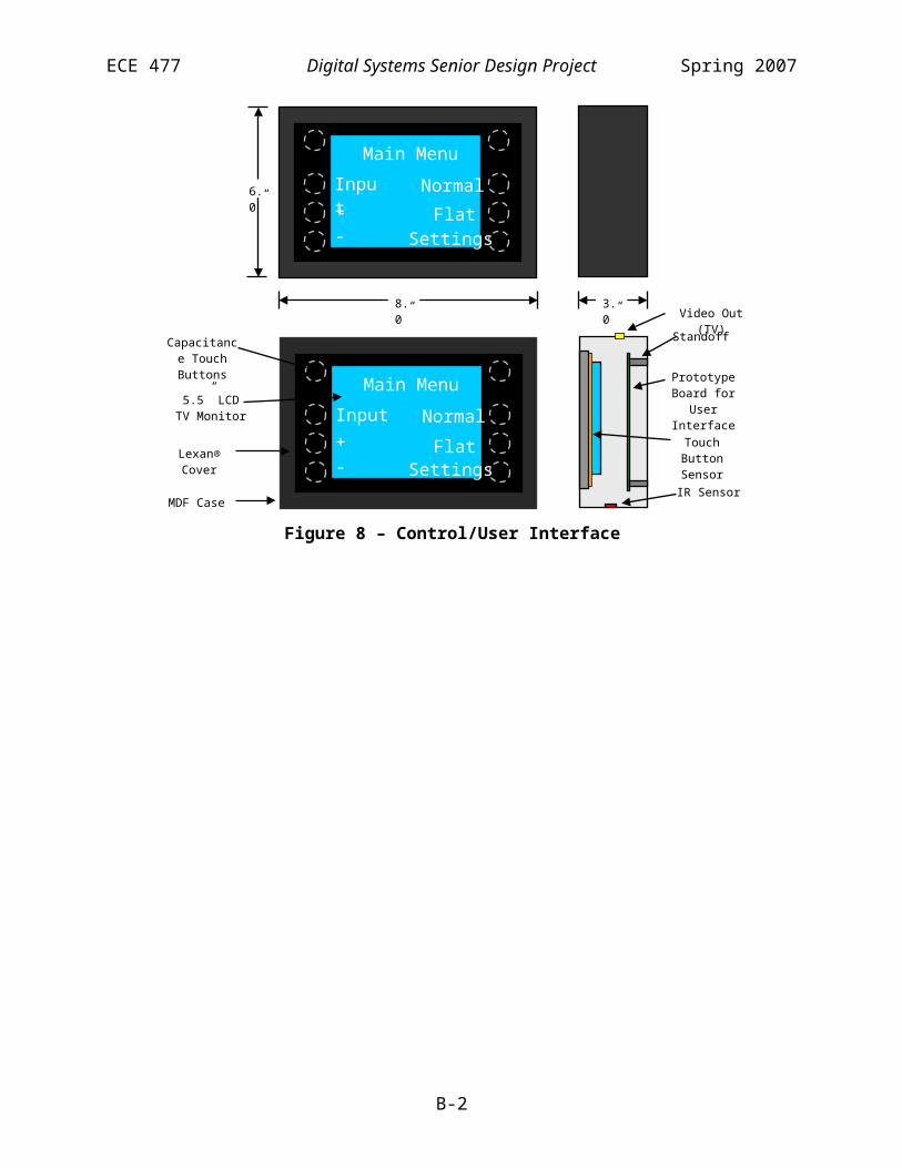
ECE 477 Digital Systems Senior Design Project Spring 2007
File: audio.h
/****************************************************************************** * Title: * Version: $Revision: 1.5 $ * Filename: $RCSfile: audio.h,v $ * Author(s): Benjamin Fogle $Author: 477grp7 $ * Created: 1/16/2007 * * Purpose: Contains all audio related functions, variables, etc. * * Update history: * $Log: audio.h,v $ * Revision 1.5 2007/04/26 15:35:15 477grp7 * Futher code cleanup. Changed how the subwoofer volume is calculated * based on a change in the subwoofer volume circuit * * Revision 1.4 2007/04/24 01:39:52 477grp7 * Cleaned up code, moved some functions to more logical places (e.g., Wait()) * and removed obsolete declarations. * * Revision 1.3 2007/04/18 01:23:41 477grp7 * Finishing wireless commands and also modifying the steering routine for * multiple sets of delays on one channel. * * Revision 1.2 2007/04/11 20:11:12 477grp7 * Major update to command processing/packet interpretation. Was going * to optimize wireless initialization routine, but wireless was acting very very * strange. * * Revision 1.1 2007/04/11 02:28:52 477grp7 * Working on wireless commands. Cleaning up code a little * * Revision 1.0 2007/03/25 16:45:57 477grp7 * Made major revisions to the structure of the project. It is now organized * more closely according to funtion. (All audio related routines are in * audio.cpp, and all wireless command routines are in commands.cpp, etc.) * More work has been done on the framework for the command routine. * The old files are preserved to make the log of changes easily available. * (io.h, wifi.h, interrupts.cpp, classes.cpp are now unused.) * * Revision 0.0 2007/01/17 00:22:05 477grp7 * Initial project creation * * *****************************************************************************/
#ifndef AUDIO_H#define AUDIO_H
/****************************************************************************** * Constants *****************************************************************************/
/****************************************************************************** * Functions *****************************************************************************/
F-4

ECE 477 Digital Systems Senior Design Project Spring 2007
void InitAudio();
void OnRecieved(int sig_int); // Interrupt routine
void DisableAudio(); // For loss of communication. Does _not_ power downvoid EnableAudio(); // (Re)establisment of communication.
void SetVolume(int vol);void SetWoofer(float relvol); // Set relative volume of the woofervoid SetDelays(int stereo, int* Data);void SetShading(int stereo, float* Data);
/****************************************************************************** * Variables *****************************************************************************/
#endif
F-5

ECE 477 Digital Systems Senior Design Project Spring 2007
File: commands.h
/****************************************************************************** * Title: * Version: $Revision: 1.4 $ * Filename: $RCSfile: commands.h,v $ * Author(s): Benjamin Fogle $Author: 477grp7 $ * Created: 1/16/2007 * * Purpose: Contains functions for processing commands received from the * control box via the wireless interface. These are high-level * functions. The low-level i/o is in system.h and io.cpp * * Update history: * $Log: commands.h,v $ * Revision 1.4 2007/04/24 01:39:53 477grp7 * Cleaned up code, moved some functions to more logical places (e.g., Wait()) * and removed obsolete declarations. * * Revision 1.3 2007/04/23 15:43:57 477grp7 * no message * * Revision 1.2 2007/04/18 01:23:41 477grp7 * Finishing wireless commands and also modifying the steering routine for * multiple sets of delays on one channel. * * Revision 1.1 2007/04/11 20:11:12 477grp7 * Major update to command processing/packet interpretation. Was going * to optimize wireless initialization routine, but wireless was acting very very * strange. * * Revision 1.0 2007/03/25 16:45:57 477grp7 * Made major revisions to the structure of the project. It is now organized * more closely according to funtion. (All audio related routines are in * audio.cpp, and all wireless command routines are in commands.cpp, etc.) * More work has been done on the framework for the command routine. * The old files are preserved to make the log of changes easily available. * (io.h, wifi.h, interrupts.cpp, classes.cpp are now unused.) * * Revision 0.2 2007/03/19 16:58:49 477grp7 * Added hardware timer support. Added framework for command processing * * Revision 0.1 2007/03/14 16:20:17 477grp7 * Began adding framework for wireless command handling * * Revision 0.0 2007/01/17 00:22:05 477grp7 * Initial project creation * * *****************************************************************************/
#ifndef COMMANDS_H#define COMMANDS_H
/******************************************************************************
F-6

ECE 477 Digital Systems Senior Design Project Spring 2007
* Constants *****************************************************************************/ #define CMD_SET 0x1#define CMD_SET_DELAY 0x6#define CMD_SET_SHADING 0x5
/****************************************************************************** * Classes *****************************************************************************/
// These classes can only be created by the ExtractPacket() function// It is essential that all classes friend that functionclass CReceivePacket{protected: CReceivePacket(int* RawData) {}
CReceivePacket() {}friend CReceivePacket* ExtractPacket(int* RawData);
public: int Destination; // Left = 0, Right = 1 int Type;};
class CSetPacket : public CReceivePacket{protected:
CSetPacket(int* RawData);CSetPacket() {}friend CReceivePacket* ExtractPacket(int* RawData);
public:int CustomEq;
int CustomSteering; int Power; int InputSelect; int Volume; int Steering; int Equalizer;};
class CDlyPacket : public CReceivePacket{protected:
CDlyPacket(int* RawData);CDlyPacket() {}friend CReceivePacket* ExtractPacket(int* RawData);
public:int Stereo;int Delay[8];
};
F-7

ECE 477 Digital Systems Senior Design Project Spring 2007
class CShdPacket : public CReceivePacket{protected:
CShdPacket(int* RawData);CShdPacket() {}friend CReceivePacket* ExtractPacket(int* RawData);
public:int Index;int Stereo;int Values[4];
};
/****************************************************************************** * Functions *****************************************************************************/
CReceivePacket* ExtractPacket(int* RawData); // RawData is 2 word arrayint ProcessCommand(CReceivePacket* pPacket);
#endif
F-8

ECE 477 Digital Systems Senior Design Project Spring 2007
File: DSP.h
/****************************************************************************** * Title: * Version: $Revision: 1.9 $ * Filename: $RCSfile: DSP.h,v $ * Author(s): Benjamin Fogle * $Author: 477grp7 $ * Created: 1/16/2007 * * Purpose: Main include file for the project * * Update history: * $Log: DSP.h,v $ * Revision 1.9 2007/04/26 15:35:15 477grp7 * Futher code cleanup. Changed how the subwoofer volume is calculated * based on a change in the subwoofer volume circuit * * Revision 1.8 2007/04/24 17:54:41 477grp7 * Cascaded equalizer and crossover filters to make 4th order filters. * * Revision 1.7 2007/04/24 01:39:53 477grp7 * Cleaned up code, moved some functions to more logical places (e.g., Wait()) * and removed obsolete declarations. * * Revision 1.6 2007/04/23 15:43:57 477grp7 * no message * * Revision 1.5 2007/04/18 23:54:25 477grp7 * Added support for multiple 'voices' with different sets of shading/delays. * Added PCB_PATCH and AUDIO_TEST defines to make testing easier * * Revision 1.4 2007/04/18 01:23:41 477grp7 * Finishing wireless commands and also modifying the steering routine for * multiple sets of delays on one channel. * * Revision 1.3 2007/04/12 18:46:55 477grp7 * no message * * Revision 1.2 2007/04/11 20:11:12 477grp7 * Major update to command processing/packet interpretation. Was going * to optimize wireless initialization routine, but wireless was acting very very * strange. * * Revision 1.1 2007/04/11 02:28:52 477grp7 * Working on wireless commands. Cleaning up code a little * * Revision 1.0 2007/03/25 16:45:57 477grp7 * Made major revisions to the structure of the project. It is now organized * more closely according to funtion. (All audio related routines are in * audio.cpp, and all wireless command routines are in commands.cpp, etc.) * More work has been done on the framework for the command routine. * The old files are preserved to make the log of changes easily available. * (io.h, wifi.h, interrupts.cpp, classes.cpp are now unused.) * * Revision 0.28 2007/03/14 16:19:51 477grp7 * Began adding framework for wireless command handling * * Revision 0.27 2007/03/09 02:53:45 477grp7 * Cleaned up comments / old code slightly * * Revision 0.26 2007/03/08 22:11:45 477grp7 * Moved FIR coefficients to program memory, allowing the time spent in the
F-9

ECE 477 Digital Systems Senior Design Project Spring 2007
* inner loop to be cut in half. Working on wireless reciever. * * Revision 0.25 2007/03/01 15:53:11 477grp7 * Fixed a bug in the SPI flag settings that caused the codec to be active * while the wireless module was being configured, causing data corruption. * Loads equalizers from Flash memory. * * Revision 0.24 2007/02/26 18:21:29 477grp7 * Working on loading data from Flash memory. * * Revision 0.23 2007/02/26 14:35:48 477grp7 * Adding support for loading new delay coefficients. Contintuing work on * wireless module * * Revision 0.22 2007/02/21 16:23:37 477grp7 * no message * * Revision 0.21 2007/02/20 22:17:45 477grp7 * Moved delay line back to main memory, since 100ms delays will suffice * * Revision 0.20 2007/02/20 16:53:12 477grp7 * no message * * Revision 0.19 2007/02/12 16:54:16 477grp7 * Fixed bug in interfacing to external SRAM * * Revision 0.18 2007/02/07 03:51:04 477grp7 * no message * * Revision 0.17 2007/02/06 19:51:58 477grp7 * Attempting to move delay line to external memory * * Revision 0.16 2007/02/06 03:07:56 477grp7 * Cleaned up old comments. Trying to make EqCoeff work as program memory to speed up loop. * * Revision 0.15 2007/02/05 18:08:22 477grp7 * Began adding wifi transmitter support * * Revision 0.14 2007/02/05 15:56:33 477grp7 * Finished converting data structures to C++ support. Amplitude shading and * delays seem to work. * * Revision 0.13 2007/02/02 21:16:25 477grp7 * Added C++ classes to make the updating algorithm more clear. * * Revision 0.12 2007/01/31 04:43:09 477grp7 * no message * * Revision 0.10 2007/01/30 18:43:32 477grp7 * Began seperating audio channels and adding capability for * two channels per speaker. * * Revision 0.9 2007/01/24 17:38:04 477grp7 * *** empty log message *** * * Revision 0.8 2007/01/24 14:21:16 477grp7 * Got talk-thru working. Optimization MUST be enabled or it won't be fast enough to process at 42000. MAX_TAPS doesn't work at 1024, but does at 512. * * Revision 0.7 2007/01/23 18:28:18 477grp7 * Preliminary delay / equilizer created. *
F-10
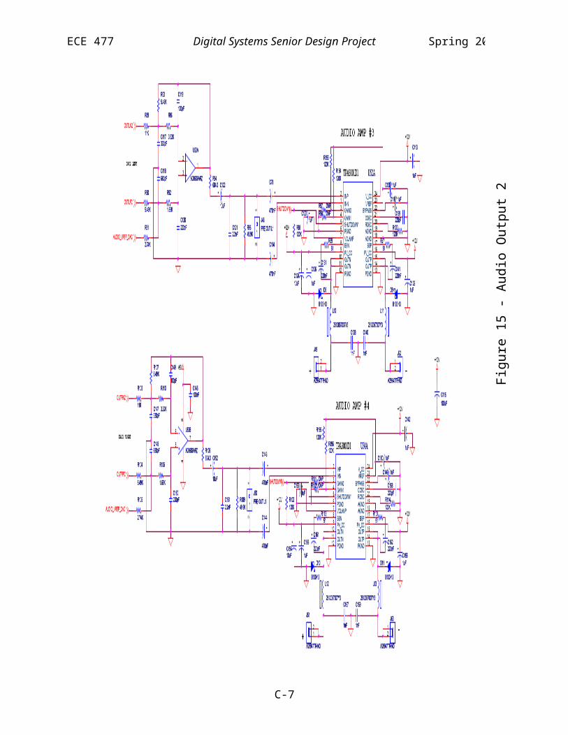
ECE 477 Digital Systems Senior Design Project Spring 2007
* Revision 0.6 2007/01/23 16:41:37 477grp7 * *** empty log message *** * * Revision 0.5 2007/01/23 15:12:48 477grp7 * Began adding code to get the audio in/out working. * * Revision 0.4 2007/01/19 18:57:55 477grp7 * Began adding codec support. Changed project to be a loader file that can be programmed into flash. * * Revision 0.3 2007/01/18 03:42:05 477grp7 * Initial test of DSP functions. Tests LEDs/external memory access * via DMA parallel port write. * * Revision 0.2 2007/01/17 18:12:16 477grp7 * Added inline DMA parallel port read routines * * Revision 0.1 2007/01/17 01:18:59 477grp7 * Began adding function prototypes * * Revision 0.0 2007/01/17 00:22:05 477grp7 * Initial project creation * * *****************************************************************************/
#ifndef DSP_H#define DSP_H
/***************************************************************************** * Testing modes ****************************************************************************/
// Uncomment to activate#define PCB_PATCH // Defined when running from the final PCB//#define AUDIO_TEST // Bypass all wireless functions and play//#define PING_TEST // Enable audio by default and accept any receive as valid//#define PASSTHRU_TEST // Bypass all filters/delays/etc.
/***************************************************************************** * Constants ****************************************************************************/ // Misc numerical constants#define NUM_SAMPLES 4800 // = sample rate * max delay#define NUM_CHANNELS 8 // # of elements
#define STEREO_LEFT 0#define STEREO_RIGHT 1
#define VOICE_MAIN 0#define VOICE_CENTER 1#define VOICE_AUX 2
#define ADC_MAX ((float)0x007FFFFF)
F-11

ECE 477 Digital Systems Senior Design Project Spring 2007
// Woofer control#define WOOFER_VOL 1.0f // Default relative woofer volume#define BASE_EQ_WOOFER 2.0f // Bass volume in bass mode#define WOOFER_BASELINE 0x7F // setting that is equivalent to 0dB
// Addresses#define FLASH_START 0x1000000#define EQ_START 0x1080000#define DELAY_START 0x10F0000#define SHADING_START 0x10F8000#define SRAM_START 0x1200000 // only for in-circuit programming now
// Wireless constants#define SPEAKER_LEFT 0x01#define SPEAKER_RIGHT 0x02#define SPEAKER_SIDE SPEAKER_LEFT // which speaker this is loaded into#define PACKET_SIZE 64 // in bits#define SPEAKER_ADDR 0x18E7 // Address of this speaker. (High byte always 0x18)#define CONTROL_ADDR 0x18E7 // address of control box. never changes#define RX_CHANNEL 2 // Wireless channel#define BLACKOUT_TIME 50000 // Approx max time between packets (in 0.1 ms)
// Filters#define CORRECTION_FILTER 32 // Which index it's stored at#define CROSSOVER_FILTER 33
/***************************************************************************** * Classes/Types ****************************************************************************/
typedef unsigned int UINT;
/***************************************************************************** * Functions ****************************************************************************/ void Init(); // Initialize everything. Do bare minimum and call the others
/***************************************************************************** * Variables ****************************************************************************/
#endif
F-12

ECE 477 Digital Systems Senior Design Project Spring 2007
File: system.h
/****************************************************************************** * Title: * Version: $Revision: 1.8 $ * Filename: $RCSfile: system.h,v $ * Author(s): Benjamin Fogle $Author: 477grp7 $ * Created: 1/16/2007 * * Purpose: Contains system status and low-level i/o functions and * variables * * Update history: * $Log: system.h,v $ * Revision 1.8 2007/04/24 01:41:34 477grp7 * Cleaned up code, moved some functions to more logical places (e.g., Wait()) * and removed obsolete declarations. * * Revision 1.7 2007/04/24 01:39:53 477grp7 * Cleaned up code, moved some functions to more logical places (e.g., Wait()) * and removed obsolete declarations. * * Revision 1.6 2007/04/22 18:58:39 477grp7 * no message * * Revision 1.5 2007/04/18 23:54:25 477grp7 * Added support for multiple 'voices' with different sets of shading/delays. * Added PCB_PATCH and AUDIO_TEST defines to make testing easier * * Revision 1.4 2007/04/18 01:23:41 477grp7 * Finishing wireless commands and also modifying the steering routine for * multiple sets of delays on one channel. * * Revision 1.3 2007/04/12 18:46:55 477grp7 * no message * * Revision 1.2 2007/04/11 20:11:12 477grp7 * Major update to command processing/packet interpretation. Was going * to optimize wireless initialization routine, but wireless was acting very very * strange. * * Revision 1.1 2007/04/11 02:28:52 477grp7 * Working on wireless commands. Cleaning up code a little * * Revision 1.0 2007/03/25 16:45:58 477grp7 * Made major revisions to the structure of the project. It is now organized * more closely according to funtion. (All audio related routines are in * audio.cpp, and all wireless command routines are in commands.cpp, etc.) * More work has been done on the framework for the command routine. * The old files are preserved to make the log of changes easily available. * (io.h, wifi.h, interrupts.cpp, classes.cpp are now unused.) * * Revision 0.0 2007/01/17 00:22:05 477grp7 * Initial project creation * * *****************************************************************************/
#ifndef SYSTEM_H#define SYSTEM_H
F-13
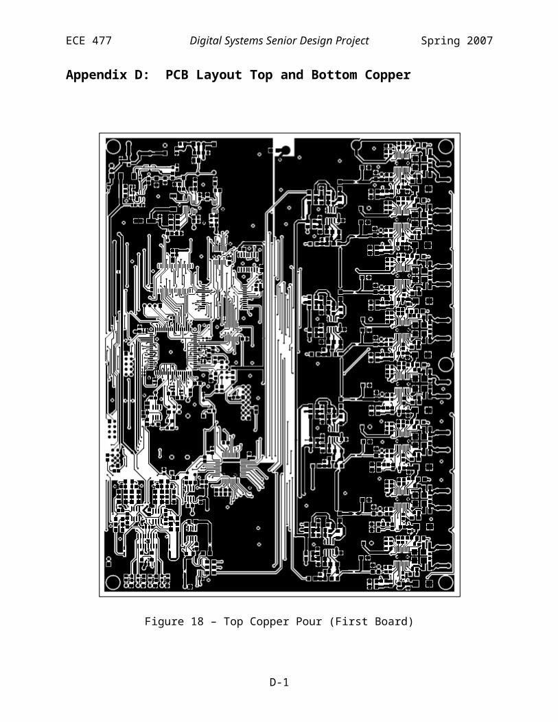
ECE 477 Digital Systems Senior Design Project Spring 2007
/****************************************************************************** * Constants *****************************************************************************/
/****************************************************************************** * Data types *****************************************************************************/
// Forward declarations. Declared in commands.hclass CReceivePacket;class CSendPacket;
/****************************************************************************** * Variables *****************************************************************************/ /****************************************************************************** * Functions *****************************************************************************/
// System status routinesvoid LoadSteering(int index);void LoadEq(int index);void SelectInput(int input);void PowerDown();void PowerUp();
// Init routinesvoid InitIO();void InitSystem();void InitWireless(int Channel, int RxAddr, int rx);
// Wireless communicationCReceivePacket* ReadWireless(); // returns "static" object. Not thread safe
// Miscvoid Wait(int us); // Idles until 'us' microseconds elapse. (Very accurate)
#endif
F-14

ECE 477 Digital Systems Senior Design Project Spring 2007
File: main.cpp
/****************************************************************************** * Title: * Version: $Revision: 1.14 $ * Filename: $RCSfile: main.cpp,v $ * Author(s): Benjamin Fogle $Author: 477grp7 $ * Created: 1/16/2007 * * Purpose: * * Update history: * $Log: main.cpp,v $ * Revision 1.14 2007/04/26 15:35:15 477grp7 * Futher code cleanup. Changed how the subwoofer volume is calculated * based on a change in the subwoofer volume circuit * * Revision 1.13 2007/04/24 17:54:42 477grp7 * Cascaded equalizer and crossover filters to make 4th order filters. * * Revision 1.12 2007/04/24 01:39:53 477grp7 * Cleaned up code, moved some functions to more logical places (e.g., Wait()) * and removed obsolete declarations. * * Revision 1.11 2007/04/23 15:43:57 477grp7 * no message * * Revision 1.10 2007/04/22 18:58:39 477grp7 * no message * * Revision 1.8 2007/04/18 23:54:25 477grp7 * Added support for multiple 'voices' with different sets of shading/delays. * Added PCB_PATCH and AUDIO_TEST defines to make testing easier * * Revision 1.7 2007/04/18 01:23:41 477grp7 * Finishing wireless commands and also modifying the steering routine for * multiple sets of delays on one channel. * * Revision 1.6 2007/04/12 18:46:55 477grp7 * no message * * Revision 1.5 2007/04/11 20:11:12 477grp7 * Major update to command processing/packet interpretation. Was going * to optimize wireless initialization routine, but wireless was acting very very * strange. * * Revision 1.4 2007/04/11 02:28:52 477grp7 * Working on wireless commands. Cleaning up code a little * * Revision 1.3 2007/04/11 00:52:48 477grp7 * no message * * Revision 1.2 2007/04/08 23:02:40 477grp7 * Got wireless working finally. * * Revision 1.1 2007/03/28 13:53:00 477grp7 * no message * * Revision 1.0 2007/03/25 16:45:58 477grp7 * Made major revisions to the structure of the project. It is now organized * more closely according to funtion. (All audio related routines are in * audio.cpp, and all wireless command routines are in commands.cpp, etc.)
F-15

ECE 477 Digital Systems Senior Design Project Spring 2007
* More work has been done on the framework for the command routine. * The old files are preserved to make the log of changes easily available. * (io.h, wifi.h, interrupts.cpp, classes.cpp are now unused.) * * Revision 0.18 2007/03/08 22:11:45 477grp7 * Moved FIR coefficients to program memory, allowing the time spent in the * inner loop to be cut in half. Working on wireless reciever. * * Revision 0.17 2007/02/26 18:21:29 477grp7 * Working on loading data from Flash memory. * * Revision 0.16 2007/02/26 14:35:48 477grp7 * Adding support for loading new delay coefficients. Contintuing work on * wireless module * * Revision 0.15 2007/02/21 01:42:50 477grp7 * no message * * Revision 0.14 2007/02/20 22:17:45 477grp7 * Moved delay line back to main memory, since 100ms delays will suffice * * Revision 0.13 2007/02/20 16:53:12 477grp7 * no message * * Revision 0.12 2007/02/19 15:23:10 477grp7 * no message * * Revision 0.11 2007/02/16 15:11:45 477grp7 * working on WiFi configuration * * Revision 0.10 2007/02/06 19:51:58 477grp7 * Attempting to move delay line to external memory * * Revision 0.9 2007/02/06 03:07:56 477grp7 * Cleaned up old comments. Trying to make EqCoeff work as program memory to speed up loop. * * Revision 0.8 2007/02/05 15:56:33 477grp7 * Finished converting data structures to C++ support. Amplitude shading and * delays seem to work. * * Revision 0.7 2007/02/02 21:16:25 477grp7 * Added C++ classes to make the updating algorithm more clear. * * Revision 0.6 2007/01/30 18:43:32 477grp7 * Began seperating audio channels and adding capability for * two channels per speaker. * * Revision 0.5 2007/01/24 17:38:04 477grp7 * *** empty log message *** * * Revision 0.4 2007/01/24 14:21:16 477grp7 * Got talk-thru working. Optimization MUST be enabled or it won't be fast enough to process at 42000. MAX_TAPS doesn't work at 1024, but does at 512. * * Revision 0.3 2007/01/23 18:28:18 477grp7 * Preliminary delay / equilizer created. * * Revision 0.2 2007/01/18 03:42:05 477grp7 * Initial test of DSP functions. Tests LEDs/external memory access * via DMA parallel port write. * * Revision 0.1 2007/01/17 01:18:07 477grp7
F-16

ECE 477 Digital Systems Senior Design Project Spring 2007
* no message * * Revision 0.0 2007/01/17 00:22:05 477grp7 * Initial project creation * * *****************************************************************************/
#include <def21262.h>#include <cdef21262.h>#include <21262.h>#include <sysreg.h>#include <sru.h>
#include "DSP.h"#include "commands.h"#include "system.h"#include "audio.h"
// Optimization does funny things to called functions#pragma optimize_offvoid main(){ CReceivePacket* pPacket = 0;
int i;int power = 0;
Init(); #if defined(AUDIO_TEST) || defined(PING_TEST)// Testing mode
PowerUp();LoadEq(0);SetVolume(0xFFFF); //MaxLoadSteering(0);EnableAudio();power = 1;
#endif // defined(AUDIO_TEST) || defined(PING_TEST)
while(1) {#if !defined(AUDIO_TEST) // If after 3s we hear nothing valid, assume comm was lost for (i = 0; i < BLACKOUT_TIME; i++) { pPacket = ReadWireless(); // get data or time out at 0.1ms if(ProcessCommand(pPacket)) { break; // if it was good, restart the loop } } if (i == BLACKOUT_TIME) { // Timed out. Re-establish communication. Everything will // go back to normal once we receive a SET packet again. PowerDown(); // no sound comes out when we don't have communication DisableAudio(); power = 0; }#endif // !defined(AUDIO_TEST) }
F-17

ECE 477 Digital Systems Senior Design Project Spring 2007
}
F-18

ECE 477 Digital Systems Senior Design Project Spring 2007
File: audio.cpp
/****************************************************************************** * Title: * Version: $Revision: 1.12 $ * Filename: $RCSfile: audio.cpp,v $ * Author(s): Benjamin Fogle $Author: 477grp7 $ * Created: 1/16/2007 * * Purpose: Code for all audio-related classes and functions * * Update history: * $Log: audio.cpp,v $ * Revision 1.12 2007/04/26 15:35:15 477grp7 * Futher code cleanup. Changed how the subwoofer volume is calculated * based on a change in the subwoofer volume circuit * * Revision 1.11 2007/04/24 17:54:40 477grp7 * Cascaded equalizer and crossover filters to make 4th order filters. * * Revision 1.10 2007/04/24 01:39:52 477grp7 * Cleaned up code, moved some functions to more logical places (e.g., Wait()) * and removed obsolete declarations. * * Revision 1.9 2007/04/23 15:43:57 477grp7 * no message * * Revision 1.8 2007/04/22 18:58:39 477grp7 * no message * * Revision 1.7 2007/04/19 01:34:21 477grp7 * fixed bug in PCB_PATCH preprocessor logic. * * Revision 1.6 2007/04/18 23:54:25 477grp7 * Added support for multiple 'voices' with different sets of shading/delays. * Added PCB_PATCH and AUDIO_TEST defines to make testing easier * * Revision 1.5 2007/04/18 01:23:41 477grp7 * Finishing wireless commands and also modifying the steering routine for * multiple sets of delays on one channel. * * Revision 1.4 2007/04/12 18:46:55 477grp7 * no message * * Revision 1.3 2007/04/11 20:11:12 477grp7 * Major update to command processing/packet interpretation. Was going * to optimize wireless initialization routine, but wireless was acting very very * strange. * * Revision 1.2 2007/04/11 02:28:52 477grp7 * Working on wireless commands. Cleaning up code a little * * Revision 1.1 2007/03/28 13:53:00 477grp7 * no message * * Revision 1.0 2007/03/25 16:45:57 477grp7 * Made major revisions to the structure of the project. It is now organized * more closely according to funtion. (All audio related routines are in * audio.cpp, and all wireless command routines are in commands.cpp, etc.) * More work has been done on the framework for the command routine. * The old files are preserved to make the log of changes easily available. * (io.h, wifi.h, interrupts.cpp, classes.cpp are now unused.)
F-19

ECE 477 Digital Systems Senior Design Project Spring 2007
* * Revision 0.0 2007/01/17 00:22:05 477grp7 * Initial project creation * * *****************************************************************************/#include <21262.h>#include <def21262.h>#include <cdef21262.h>#include <sysreg.h>#include <sru.h>#include <signal.h>
#include "DSP.h"#include "audio.h"#include "ad1835.h"#include "system.h"
/***************************************************************************** * Class declarations ****************************************************************************/
// Not a class declaration, but used by inline functions in the classes, and// so must appear herestatic int Stereo = 1;
// Note most functions are inline for performance reasons
// CDelayList holds a set of delays for each speaker element and each// stereo pair, making a total of 16 delays.class CDelayList{public: CDelayList(); ~CDelayList() {} // Each stereo channel (L/R) a delay, and there are 8 elements in all // stereo = STEREO_LEFT,STEREO_RIGHT. element = 0-7 int operator() (int stereo, int element) const { return List[stereo][element]; } int& operator() (int stereo, int element) { return List[stereo][element]; } // Functions for modifying _active_ elements (elemnts 0-3 or 4-7 depending // on cycle) stereo = STEREO_LEFT,STEREO_RIGHT. element = 0-3 int GetActive(int stereo, int element) const { return List[stereo][(Stereo * 4) + element]; } void Load(int index, int subindex); private:
int List[2][NUM_CHANNELS];
F-20

ECE 477 Digital Systems Senior Design Project Spring 2007
friend void SetDelays(int stereo, int* Data); // external interface};
// CShadingList holds a set of shading for each speaker element and each// stereo pair, making a total of 16 delays.class CShadingList{public: CShadingList(); ~CShadingList() {} // Each stereo channel (L/R) a delay, and there are 8 elements in all // stereo = STEREO_LEFT,STEREO_RIGHT. element = 0-7 float operator() (int stereo, int element) const { return List[stereo][element]; } float& operator() (int stereo, int element) { return List[stereo][element]; } // Functions for modifying _active_ elements (elemnts 0-3 or 4-7 depending // on cycle). stereo = STEREO_LEFT,STEREO_RIGHT. element = 0-3 float GetActive(int stereo, int element) const { return List[stereo][(Stereo << 2) + element]; } void Load(int index, int subindex);private:
float List[2][NUM_CHANNELS];friend void SetShading(int stereo, float* Data);
};
// CStereoDelayLine class holds a stereo pair of delay lines// You can read from either channel, but only write to the active one
class CStereoDelayLine{public:
CStereoDelayLine(); // zero everything~CStereoDelayLine() {}
void Push(float data){ if (--Start[Stereo] < 0) Start[Stereo] = NUM_SAMPLES - 1;
Data[Stereo][Start[Stereo]] = data;}
float operator() (int channel, int index) const{ // The (Stereo != channel) prevents an echo return Data[channel][(Start[Stereo] + index + (Stereo != channel)) % NUM_SAMPLES];}
private:int Start[2];float Data[2][NUM_SAMPLES];
};
F-21

ECE 477 Digital Systems Senior Design Project Spring 2007
// Class for a second-order IIR filter for a stereo// input. (Changes automatically based on Stereo// global variable).class CFilter{public:
CFilter();~CFilter();
void Load(int index); // Load from flash
float Calc(float x); // Calc from input and stored dataprotected:
float x_coeff[3];float y_coeff[2];float x_data[2][3];float y_data[2][3];int Start[2];
};
/***************************************************************************** * Global variables (static linkage) ****************************************************************************/
static CStereoDelayLine DelayLine;
static CDelayList DelayList[3];static CShadingList ShadingList[3];
static CFilter EqFilter[2]; // Cascaded to make a 4th order HPFstatic CFilter CrossoverFilter[2]; // Cascaded to make a 4th order HPFstatic CFilter CorrectionFilter;
static float MasterVolume = 1.0f;static float WooferVolume = WOOFER_VOL; // Relative woofer volume
/***************************************************************************** * Functions ****************************************************************************/
inline void WriteSPICodec(int writedata){
*pTXSPI = writedata;
for (int i = 0; i < 100; i++) asm("nop;"); // wait a bitwhile(!(*pSPISTAT & SPIF)); // wait for transfer completefor (int i = 0; i < 100; i++) asm("nop;"); // wait a bit
F-22

ECE 477 Digital Systems Senior Design Project Spring 2007
} void InitAudio(){ // Set the Signal Routing Unit (SRU) appropriately // Note that due to an error in the PCB, some pins may need to be // changed. Define PCB_PATCH to change them.
// Set audio reset: FLAG14 = AUDIO_PWR// FLAG14 --> DAI18SRU(FLAG14_O, DAI_PB18_I);SRU(HIGH, PBEN18_I);// Set to off initiallysysreg_bit_set(sysreg_FLAGS, FLG14);
// PB17 -- audio osc input
// Set PB17 to input (MCLK in) SRU(LOW,DAI_PB17_I); SRU(LOW,PBEN17_I);
// ADC --> SPORT0#ifndef PCB_PATCH SRU(DAI_PB07_O,SPORT0_CLK_I); // SPORT0_CLK = PB07#else SRU(DAI_PB03_O,SPORT0_CLK_I); // SPORT0_CLK = PB03 #endif SRU(DAI_PB08_O,SPORT0_FS_I); // SPORT0_FS = PB08 SRU(DAI_PB05_O,SPORT0_DA_I); // SPORT0_DA (Rx channel A) = PB05 // Tie their unused buffers low to avoid rare errors, (according to specs)#ifndef PCB_PATCH SRU(LOW,DAI_PB07_I); #else SRU(LOW,DAI_PB03_I); #endif SRU(LOW,DAI_PB08_I); SRU(LOW,DAI_PB05_I); // make inputs#ifndef PCB_PATCH SRU(LOW,PBEN07_I);#else SRU(LOW,PBEN03_I); #endif SRU(LOW,PBEN08_I); SRU(LOW,PBEN05_I); // Connect DACs to SPORTs (note that each SPORT does double-duty) // SPORT1 --> DAC1 SRU(SPORT1_DB_O, DAI_PB11_I); // Tx channel B to pb9 // SPORT1 --> DAC2 SRU(SPORT1_DA_O, DAI_PB12_I); // Tx channel A to pb10 // SPORT2 --> DAC3#ifndef PCB_PATCH SRU(SPORT2_DB_O, DAI_PB09_I);#else SRU(SPORT2_DB_O, DAI_PB02_I);#endif // SPORT2 --> DAC4 SRU(SPORT2_DA_O, DAI_PB10_I); // clk and fs signals generated by the input are reproduced exactly // on the outputs of SPORT1 and SPORT2. Do this by routing the inputs
F-23

ECE 477 Digital Systems Senior Design Project Spring 2007
// of the pins running SPORT0 directly to the inputs of SPORT1 and SPORT2, // and then also connect them to the outputs.#ifndef PCB_PATCH SRU(DAI_PB07_O, SPORT1_CLK_I); SRU(DAI_PB07_O, SPORT2_CLK_I);#else SRU(DAI_PB03_O, SPORT1_CLK_I); SRU(DAI_PB03_O, SPORT2_CLK_I);#endif SRU(DAI_PB08_O, SPORT1_FS_I); SRU(DAI_PB08_O, SPORT2_FS_I); #ifndef PCB_PATCH SRU(DAI_PB07_O,DAI_PB13_I);#else SRU(DAI_PB03_O,DAI_PB13_I);#endif SRU(DAI_PB17_O,DAI_PB06_I); SRU(DAI_PB08_O,DAI_PB14_I); // Set SPORT1 and SPORT2 pins as outputs SRU(HIGH,PBEN06_I);#ifndef PCB_PATCH SRU(HIGH,PBEN09_I);#else SRU(HIGH,PBEN02_I);#endif SRU(HIGH,PBEN10_I); SRU(HIGH,PBEN11_I); SRU(HIGH,PBEN12_I); SRU(HIGH,PBEN13_I); SRU(HIGH,PBEN14_I); // Now initialize the serial ports themselves *pSPMCTL01 = 0; *pSPMCTL23 = 0; // SPORT0 is recieving in I2C mode, 24bit, using channel A *pSPCTL0 = (BHD | SPEN_A | OPMODE | SLEN24); // SPORT1 is transmitting in I2C mode, 24bit, using channels A and B *pSPCTL1 = (BHD | SPEN_A | SPEN_B | OPMODE | SPTRAN | SLEN24);
// SPORT2 is transmitting in I2C mode, 24bit, using channels A and B *pSPCTL2 = (BHD | SPEN_A | SPEN_B | OPMODE | SPTRAN | SLEN24); // Now init the codec via spi // set up SPI *pSPICTL |= TXFLSH | RXFLSH; // clear invalid data *pSPIFLG = 0; *pSPIBAUD = 100; // 0.5Mbps *pSPIFLG = 0xF708; // FLAG3 *pSPICTL = SPIEN | SPIMS | MSBF | WL16 | TIMOD1; WriteSPICodec(WR | DACCTRL1 | DACI2S | DAC24BIT | DACFS48); WriteSPICodec(WR | DACCTRL2 ); WriteSPICodec(WR | DACVOL_L1 | DACVOL_MAX); WriteSPICodec(WR | DACVOL_R1 | DACVOL_MAX); WriteSPICodec(WR | DACVOL_L2 | DACVOL_MAX); WriteSPICodec(WR | DACVOL_R2 | DACVOL_MAX); WriteSPICodec(WR | DACVOL_L3 | DACVOL_MAX); WriteSPICodec(WR | DACVOL_R3 | DACVOL_MAX);
F-24

ECE 477 Digital Systems Senior Design Project Spring 2007
WriteSPICodec(WR | DACVOL_L4 | DACVOL_MAX); WriteSPICodec(WR | DACVOL_R4 | DACVOL_MAX); WriteSPICodec(WR | ADCCTRL1 | ADCFS48); WriteSPICodec(WR | ADCCTRL2 | ADCI2S | ADC24BIT); WriteSPICodec(WR | ADCCTRL3 | IMCLKx2);
// Load crossover and correction filters CorrectionFilter.Load(CORRECTION_FILTER); CrossoverFilter[0].Load(CROSSOVER_FILTER); CrossoverFilter[1].Load(CROSSOVER_FILTER);
// interrupts// Note that the main interrupt (SIG_SP0) is left undefined. This// ensures that the audio starts in a disabled state
interrupts(SIG_SP0, SIG_IGN);interrupts(SIG_IRQ1, SIG_IGN);interrupts(SIG_IRQ2, SIG_IGN);
}
void OnRecieved(int sig_int){ int temp; float x; float y; int LeftIndex[3]; int RightIndex[3];
// Read the sampletemp = *pRXSP0A;
#if !defined(PASSTHRU_TEST)if (temp & 0x00800000) // sign extend from 24-bit signed to 32-bit
signed temp |= 0xFF000000; // convert to float in range [-1.0, 1.0] x = (float)temp / ADC_MAX;
// Run it through all the filtersy = CrossoverFilter[0].Calc(x); // Crossover filter is 2 cascaded
biquads y = CrossoverFilter[1].Calc(y); // to make a 4th order filtery = CorrectionFilter.Calc(y);y = EqFilter[0].Calc(y); // Eq is also cascaded to make
4th ordery = EqFilter[1].Calc(y);
// put the equalized output into the delay lineDelayLine.Push(y);
// Output 4 of the 8 speaker elements.// If Stereo = STEREO_LEFT we can update 0-3, otherwise we can update 4-7// Each element's output the sum of each input line (left and right) after// it has been equalized and all three delays applied
LeftIndex[0] = DelayList[0].GetActive(STEREO_LEFT,0);RightIndex[0] = DelayList[0].GetActive(STEREO_RIGHT, 0);LeftIndex[1] = DelayList[1].GetActive(STEREO_LEFT,0);RightIndex[1] = DelayList[1].GetActive(STEREO_RIGHT, 0);LeftIndex[2] = DelayList[2].GetActive(STEREO_LEFT,0);RightIndex[2] = DelayList[2].GetActive(STEREO_RIGHT, 0);*pTXSP1A = (int)(ADC_MAX * MasterVolume * (
F-25

ECE 477 Digital Systems Senior Design Project Spring 2007
ShadingList[0].GetActive(STEREO_LEFT, 0) * DelayLine(STEREO_LEFT, LeftIndex[0]) +
ShadingList[1].GetActive(STEREO_LEFT, 0) * DelayLine(STEREO_LEFT, LeftIndex[1]) +
ShadingList[2].GetActive(STEREO_LEFT, 0) * DelayLine(STEREO_LEFT, LeftIndex[2]) +
ShadingList[0].GetActive(STEREO_RIGHT,0) * DelayLine(STEREO_RIGHT,RightIndex[0]) +
ShadingList[1].GetActive(STEREO_RIGHT,0) * DelayLine(STEREO_RIGHT,RightIndex[1]) +
ShadingList[2].GetActive(STEREO_RIGHT,0) * DelayLine(STEREO_RIGHT,RightIndex[2])
));
LeftIndex[0] = DelayList[0].GetActive(STEREO_LEFT,1);RightIndex[0] = DelayList[0].GetActive(STEREO_RIGHT, 1);LeftIndex[1] = DelayList[1].GetActive(STEREO_LEFT,1);RightIndex[1] = DelayList[1].GetActive(STEREO_RIGHT, 1);LeftIndex[2] = DelayList[2].GetActive(STEREO_LEFT,1);RightIndex[2] = DelayList[2].GetActive(STEREO_RIGHT, 1);*pTXSP1B = (int)(ADC_MAX * MasterVolume * (
ShadingList[0].GetActive(STEREO_LEFT, 1) * DelayLine(STEREO_LEFT, LeftIndex[0]) +
ShadingList[1].GetActive(STEREO_LEFT, 1) * DelayLine(STEREO_LEFT, LeftIndex[1]) +
ShadingList[2].GetActive(STEREO_LEFT, 1) * DelayLine(STEREO_LEFT, LeftIndex[2]) +
ShadingList[0].GetActive(STEREO_RIGHT,1) * DelayLine(STEREO_RIGHT,RightIndex[0]) +
ShadingList[1].GetActive(STEREO_RIGHT,1) * DelayLine(STEREO_RIGHT,RightIndex[1]) +
ShadingList[2].GetActive(STEREO_RIGHT,1) * DelayLine(STEREO_RIGHT,RightIndex[2])
));
LeftIndex[0] = DelayList[0].GetActive(STEREO_LEFT,2);RightIndex[0] = DelayList[0].GetActive(STEREO_RIGHT, 2);LeftIndex[1] = DelayList[1].GetActive(STEREO_LEFT,2);RightIndex[1] = DelayList[1].GetActive(STEREO_RIGHT, 2);LeftIndex[2] = DelayList[2].GetActive(STEREO_LEFT,2);RightIndex[2] = DelayList[2].GetActive(STEREO_RIGHT, 2);*pTXSP2A = (int)(ADC_MAX * MasterVolume * (
ShadingList[0].GetActive(STEREO_LEFT, 2) * DelayLine(STEREO_LEFT, LeftIndex[0]) +
ShadingList[1].GetActive(STEREO_LEFT, 2) * DelayLine(STEREO_LEFT, LeftIndex[1]) +
ShadingList[2].GetActive(STEREO_LEFT, 2) * DelayLine(STEREO_LEFT, LeftIndex[2]) +
ShadingList[0].GetActive(STEREO_RIGHT,2) * DelayLine(STEREO_RIGHT,RightIndex[0]) +
ShadingList[1].GetActive(STEREO_RIGHT,2) * DelayLine(STEREO_RIGHT,RightIndex[1]) +
ShadingList[2].GetActive(STEREO_RIGHT,2) * DelayLine(STEREO_RIGHT,RightIndex[2])
));
LeftIndex[0] = DelayList[0].GetActive(STEREO_LEFT,3);RightIndex[0] = DelayList[0].GetActive(STEREO_RIGHT, 3);LeftIndex[1] = DelayList[1].GetActive(STEREO_LEFT,3);RightIndex[1] = DelayList[1].GetActive(STEREO_RIGHT, 3);LeftIndex[2] = DelayList[2].GetActive(STEREO_LEFT,3);RightIndex[2] = DelayList[2].GetActive(STEREO_RIGHT, 3);
F-26
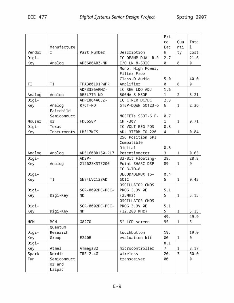
ECE 477 Digital Systems Senior Design Project Spring 2007
*pTXSP2B = (int)(ADC_MAX * MasterVolume * (ShadingList[0].GetActive(STEREO_LEFT, 3) *
DelayLine(STEREO_LEFT, LeftIndex[0]) + ShadingList[1].GetActive(STEREO_LEFT, 3) *
DelayLine(STEREO_LEFT, LeftIndex[1]) + ShadingList[2].GetActive(STEREO_LEFT, 3) *
DelayLine(STEREO_LEFT, LeftIndex[2]) + ShadingList[0].GetActive(STEREO_RIGHT,3) *
DelayLine(STEREO_RIGHT,RightIndex[0]) +ShadingList[1].GetActive(STEREO_RIGHT,3) *
DelayLine(STEREO_RIGHT,RightIndex[1]) +ShadingList[2].GetActive(STEREO_RIGHT,3) *
DelayLine(STEREO_RIGHT,RightIndex[2])));
#else // !defined(PASSTHRU_TEST)*pTXSP1A = *pTXSP1B = *pTXSP2A = *pTXSP2B = temp;
#endif // !defined(PASSTHRU_TEST)
// Each time the interrupt is called, it's for the other// stereo channel.Stereo ^= 0x01;
}
void EnableAudio(){ // Set interrupt interrupts(SIG_SP0, OnRecieved);}
void DisableAudio(){ // Turn off the interrupt interrupts(SIG_SP0, SIG_IGN);}
void SetVolume(int volume){ volume &= 0x0000FFFF;
MasterVolume = ((float)volume) / ((float)0x0000FFFF);SetWoofer(WooferVolume); // Update woofer
}
void LoadSteering(int index){ // Set up PP for flash read for(int i = 0; i < 3; i++) { DelayList[i].Load(index, i); ShadingList[i].Load(index, i); }}
void SetDelays(int stereo, int* Data){
F-27

ECE 477 Digital Systems Senior Design Project Spring 2007
// Whe setting delays manually, only one set of delays // are used
for(int i = 0; i < NUM_CHANNELS; i++)DelayList[0].List[stereo][i] = Data[i];
for (int i = 0; i < NUM_CHANNELS; i++){ DelayList[1].List[0][i] = DelayList[1].List[1][i] = DelayList[2].List[0][i] = DelayList[2].List[1][i] = 0;}
}
void SetShading(int stereo, float* Data){ for (int i = 0; i < NUM_CHANNELS; i++) ShadingList[0].List[stereo][i] = Data[i];
for (int i = 0; i < NUM_CHANNELS; i++){ ShadingList[1].List[0][i] = ShadingList[1].List[1][i] = ShadingList[2].List[0][i] = ShadingList[2].List[1][i] = 0.0f;}
}
void LoadEq(int index){ EqFilter[0].Load(2*index); EqFilter[1].Load(2*index + 1); // One exception: For bass mode, we also turn up the woofer if (index == 3) { SetWoofer(BASE_EQ_WOOFER); } else { SetWoofer(WOOFER_VOL); }}
void SetWoofer(float relvol){ WooferVolume = relvol; int woofer = WOOFER_BASELINE + ((MasterVolume * WooferVolume) - 1.0) * 0x7F; // Update the woofer volume control // Temporarily disable wireless while (!(*pSPISTAT & SPIF)); // Wait for SPI to be free sysreg_bit_clr_nop(sysreg_FLAGS, FLG11); Wait(100);
F-28

ECE 477 Digital Systems Senior Design Project Spring 2007
*pSPICTL |= TXFLSH | RXFLSH; // clear invalid data *pSPIFLG = 0; *pSPIBAUD = 100; // 0.5Mbps *pSPIFLG = 0xFE01; // FLAG0 *pSPICTL = SPIEN | SPIMS | MSBF | WL16 | TIMOD1; *pTXSPI = 0x1100 | woofer; while(!(*pSPISTAT & SPIF)); Wait(100); sysreg_bit_set_nop(sysreg_FLAGS, FLG11);}
/****************************************************************************** * Class Member functions *****************************************************************************/
CStereoDelayLine::CStereoDelayLine(){ Start[0] = Start[1] = 0; int n = 0; for (int i = 0; i < sizeof(NUM_SAMPLES); i++) { Data[0][i] = 0; Data[1][i] = 0; }}
CDelayList::CDelayList(){ }
CShadingList::CShadingList(){ }
void CDelayList::Load(int index, int subindex){ int addr = DELAY_START + (3*64)*index + 64*subindex; // wait for DMA to be free while (*pPPCTL & (PPDS | PPBS)); // Enter crit section (we don't want interruptions here) sysreg_bit_clr(sysreg_MODE1, IRPTEN); *pPPCTL = 0; *pIIPP = (int)List; *pIMPP = 1; *pICPP = sizeof(List); *pECPP = sizeof(List) * 4; *pEIPP = addr; *pEMPP = 1;
F-29

ECE 477 Digital Systems Senior Design Project Spring 2007
*pPPCTL = PPEN|PPDUR23|PPBHC|PPDEN; sysreg_bit_set(sysreg_MODE1, IRPTEN); // exit crit section}
void CShadingList::Load(int index, int subindex){ int addr = SHADING_START + (3*64)*index + 64*subindex; // wait for DMA to be free while (*pPPCTL & (PPDS | PPBS)); // Enter crit section (we don't want interruptions here) sysreg_bit_clr(sysreg_MODE1, IRPTEN); *pPPCTL = 0; *pIIPP = (int)List; *pIMPP = 1; *pICPP = sizeof(List); *pECPP = sizeof(List) * 4; *pEIPP = addr; *pEMPP = 1; *pPPCTL = PPEN|PPDUR23|PPBHC|PPDEN; sysreg_bit_set(sysreg_MODE1, IRPTEN); // exit crit section}
CFilter::CFilter(){ for(int i = 0; i < 2; i++) {
x_data[i][0] = x_data[i][1] = x_data[i][2] =y_data[i][0] = y_data[i][1] = y_data[i][2] = 0;
}
Start[0] = Start[1] = 0; }
CFilter::~CFilter(){ }
void CFilter::Load(int index){ int addr = EQ_START + (index * 5 * 4); // wait for DMA to be free while (*pPPCTL & (PPDS | PPBS));
// Enter crit section (we don't want interruptions here) sysreg_bit_set(sysreg_MODE1, IRPTEN);
*pPPCTL = 0; *pIIPP = (int)x_coeff; *pIMPP = 1; *pICPP = 5; *pECPP = 5*4; *pEIPP = addr;
F-30

ECE 477 Digital Systems Senior Design Project Spring 2007
*pEMPP = 1; *pPPCTL = PPEN|PPDUR23|PPBHC|PPDEN;
sysreg_bit_clr(sysreg_MODE1, IRPTEN); // exit crit section}
float CFilter::Calc(float x){ float res; int i = Start[Stereo]; // Add to delay line x_data[Stereo][i] = x;
y_data[Stereo][i] = x_coeff[0] * x_data[Stereo][i] +x_coeff[1] * x_data[Stereo][(i
+ 1) % 3] +x_coeff[2] * x_data[Stereo][(i
+ 2) % 3] +y_coeff[0] * y_data[Stereo][(i
+ 1) % 3] +y_coeff[1] * y_data[Stereo][(i
+ 2) % 3];
res = y_data[Stereo][i];
if (--i < 0) Start[Stereo] = 2; else Start[Stereo] = i; return res;}
F-31

ECE 477 Digital Systems Senior Design Project Spring 2007
File: commands.cpp
/****************************************************************************** * Title: * Version: $Revision: 1.10 $ * Filename: $RCSfile: commands.cpp,v $ * Author(s): Benjamin Fogle $Author: 477grp7 $ * Created: 1/16/2007 * * Purpose: Contains high-level logic for interpreting commands sent to the * speaker via the wireless interface * * Update history: * $Log: commands.cpp,v $ * Revision 1.10 2007/04/26 15:35:15 477grp7 * Futher code cleanup. Changed how the subwoofer volume is calculated * based on a change in the subwoofer volume circuit * * Revision 1.9 2007/04/24 17:54:40 477grp7 * Cascaded equalizer and crossover filters to make 4th order filters. * * Revision 1.8 2007/04/24 01:39:52 477grp7 * Cleaned up code, moved some functions to more logical places (e.g., Wait()) * and removed obsolete declarations. * * Revision 1.7 2007/04/23 15:43:57 477grp7 * no message * * Revision 1.6 2007/04/22 18:58:39 477grp7 * no message * * Revision 1.5 2007/04/18 23:54:25 477grp7 * Added support for multiple 'voices' with different sets of shading/delays. * Added PCB_PATCH and AUDIO_TEST defines to make testing easier * * Revision 1.4 2007/04/18 01:23:41 477grp7 * Finishing wireless commands and also modifying the steering routine for * multiple sets of delays on one channel. * * Revision 1.3 2007/04/12 18:46:55 477grp7 * no message * * Revision 1.2 2007/04/11 20:11:12 477grp7 * Major update to command processing/packet interpretation. Was going * to optimize wireless initialization routine, but wireless was acting very very * strange. * * Revision 1.1 2007/04/11 02:28:52 477grp7 * Working on wireless commands. Cleaning up code a little * * Revision 1.0 2007/03/25 16:45:57 477grp7 * Made major revisions to the structure of the project. It is now organized * more closely according to funtion. (All audio related routines are in * audio.cpp, and all wireless command routines are in commands.cpp, etc.) * More work has been done on the framework for the command routine. * The old files are preserved to make the log of changes easily available. * (io.h, wifi.h, interrupts.cpp, classes.cpp are now unused.) * * Revision 0.2 2007/03/19 16:58:49 477grp7 * Added hardware timer support. Added framework for command processing *
F-32

ECE 477 Digital Systems Senior Design Project Spring 2007
* Revision 0.1 2007/03/14 16:20:17 477grp7 * Began adding framework for wireless command handling * * Revision 0.0 2007/01/17 00:22:05 477grp7 * Initial project creation * * *****************************************************************************/
#include <21262.h>#include <def21262.h>#include <cdef21262.h>#include <sysreg.h>#include <signal.h>
#include "DSP.h"#include "commands.h"#include "system.h"#include "audio.h"
/****************************************************************************** * Constants *****************************************************************************/
#ifndef NULL#define NULL 0#endif
/****************************************************************************** * Global variables (static linkage) *****************************************************************************/
/****************************************************************************** * Functions *****************************************************************************/
//#pragma optimize_offCReceivePacket* ExtractPacket(int* RawData){ // We need to trick the compiler into reusing // the same block of memory (w/o library functions) // since union members may not have member functions with // this compiler static int Memory[16]; // big enough for all packets void* pMemory = Memory; // Command is bits 19-16 int command = (RawData[0] & 0x000F0000) >> 16;
F-33

ECE 477 Digital Systems Senior Design Project Spring 2007
switch (command) { case CMD_SET:
{ CSetPacket* pPacket = (CSetPacket*)pMemory; (*pPacket) = CSetPacket(RawData); return (CReceivePacket*)pMemory; }
case CMD_SET_DELAY: { CDlyPacket* pPacket = (CDlyPacket*)pMemory; (*pPacket) = CDlyPacket(RawData); return (CReceivePacket*)pMemory; }
case CMD_SET_SHADING: { CShdPacket* pPacket = (CShdPacket*)pMemory; (*pPacket) = CShdPacket(RawData); return (CReceivePacket*)pMemory; }default:
return NULL; }}
//#pragma optimize_offint ProcessCommand(CReceivePacket* pPacket){ static int index = 0; // for multiple-packet data if (!pPacket) return 0; #if defined(PING_TEST)
PowerUp(); // Turn on if neededEnableAudio(); // Turn on if neededreturn 1; // Always report good for any nonnull packet
#else
// Only respond if it was sent to us if (!(pPacket->Destination & SPEAKER_SIDE)) return 0; switch(pPacket->Type) { case CMD_SET:
{ index = 0; // housekeeping CSetPacket* pSet = (CSetPacket*)pPacket; SetVolume(pSet->Volume); SelectInput(pSet->InputSelect); LoadEq(pSet->Equalizer); if (!pSet->CustomSteering) { LoadSteering(pSet->Steering); }
if (pSet->Power && pSet->Volume != 0) { EnableAudio();
F-34
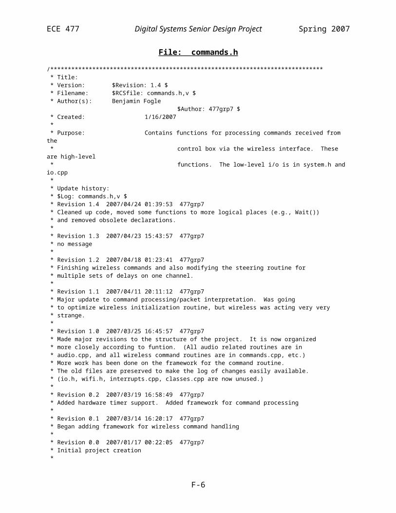
ECE 477 Digital Systems Senior Design Project Spring 2007
PowerUp(); } else // Power down for mute or power off bit { PowerDown(); DisableAudio(); } return 1; }
case CMD_SET_DELAY:{
index = 0;int DelayValues[8];
CDlyPacket* pDly = (CDlyPacket*)pPacket;
for (int i = 0; i < 8; i++) DelayValues[i] = 12 * pDly->Delay[i]; // 0.25ms = 12 samples
SetDelays(pDly->Stereo, DelayValues); // Also set the right?
return 1;}
case CMD_SET_SHADING:{ CShdPacket* pShd = (CShdPacket*)pPacket; static float ShadeValues[8];
if (index != pShd->Index) { index = 0; break; // Ignore and discard changes }
if (pShd->Index == 0) { ShadeValues[0] = (float)(pShd->Values[0]) / 100.0f; ShadeValues[1] = (float)(pShd->Values[1]) / 100.0f; ShadeValues[2] = (float)(pShd->Values[2]) / 100.0f; ShadeValues[3] = (float)(pShd->Values[3]) / 100.0f; index = 1; } else if (pShd->Index == 1) { ShadeValues[4] = (float)(pShd->Values[0]) / 100.0f; ShadeValues[5] = (float)(pShd->Values[1]) / 100.0f; ShadeValues[6] = (float)(pShd->Values[2]) / 100.0f; ShadeValues[7] = (float)(pShd->Values[3]) / 100.0f; // Apply changes index = 0; SetShading(pShd->Stereo, ShadeValues); } else { // Invalid now index = 0; break; }
return 1;}
F-35

ECE 477 Digital Systems Senior Design Project Spring 2007
default:index = 0;return 0; // Invalid
} return 0; // Shouldn't happen#endif // defined(PING_TEST)}
/****************************************************************************** * Class member functions *****************************************************************************/
CShdPacket::CShdPacket(int* RawData){
Destination = (RawData[0] & 0x00300000) >> 20;Type = (RawData[0] & 0x000F0000) >> 16;
Index = (RawData[0] & 0x0000F000) >> 12;Stereo = (RawData[0] & 0x00000100) >> 8;
Values[0] = (RawData[0] & 0x000000FF);Values[1] = (RawData[1] & 0xFF000000) >> 24;Values[2] = (RawData[1] & 0x00FF0000) >> 16;Values[3] = (RawData[1] & 0x0000FF00) >> 8;
}
CDlyPacket::CDlyPacket(int* RawData){
Destination = (RawData[0] & 0x00300000) >> 20;Type = (RawData[0] & 0x000F0000) >> 16;
Stereo = (RawData[0] & 0x00000100) >> 8;
Delay[0] = (RawData[0] & 0x000000F8) >> 3;Delay[1] = ((RawData[0] & 0x00000007) << 2) | ((RawData[1] & 0xC0000000) >> 30);Delay[2] = (RawData[1] & 0x3E000000) >> 25;Delay[3] = (RawData[1] & 0x01F00000) >> 20;Delay[4] = (RawData[1] & 0x000F8000) >> 15;Delay[5] = (RawData[1] & 0x00007C00) >> 10;Delay[6] = (RawData[1] & 0x000003E0) >> 5;Delay[7] = (RawData[1] & 0x0000001F);
}
CSetPacket::CSetPacket(int* RawData){
Destination = (RawData[0] & 0x00300000) >> 20;Type = (RawData[0] & 0x000F0000) >> 16;
CustomEq = (RawData[0] & 0x00000008) >> 3;CustomSteering = (RawData[0] & 0x00000004) >> 2;Power = (RawData[0] & 0x00000002) >> 1;InputSelect = (RawData[0] & 0x00000001);Volume = (RawData[1] & 0xFFFF0000) >> 16;
Steering = (RawData[1] & 0x0000F000) >> 12; Equalizer = (RawData[1] & 0x00000F00) >> 8;}
F-36

ECE 477 Digital Systems Senior Design Project Spring 2007
File: io.cpp
/****************************************************************************** * Title: * Version: $Revision: 1.11 $ * Filename: $RCSfile: io.cpp,v $ * Author(s): Benjamin Fogle $Author: 477grp7 $ * Created: 1/16/2007 * * Purpose: Contains code for communicating with the wireless and other * chips on the board (such as turning on/off the amplifiers) * * Update history: * $Log: io.cpp,v $ * Revision 1.11 2007/04/26 15:35:15 477grp7 * Futher code cleanup. Changed how the subwoofer volume is calculated * based on a change in the subwoofer volume circuit * * Revision 1.10 2007/04/24 17:54:41 477grp7 * Cascaded equalizer and crossover filters to make 4th order filters. * * Revision 1.9 2007/04/24 01:39:53 477grp7 * Cleaned up code, moved some functions to more logical places (e.g., Wait()) * and removed obsolete declarations. * * Revision 1.8 2007/04/23 15:43:57 477grp7 * no message * * Revision 1.7 2007/04/22 18:58:39 477grp7 * no message * * Revision 1.6 2007/04/18 01:23:41 477grp7 * Finishing wireless commands and also modifying the steering routine for * multiple sets of delays on one channel. * * Revision 1.5 2007/04/12 18:46:55 477grp7 * no message * * Revision 1.4 2007/04/11 20:11:12 477grp7 * Major update to command processing/packet interpretation. Was going * to optimize wireless initialization routine, but wireless was acting very very * strange. * * Revision 1.3 2007/04/11 02:28:52 477grp7 * Working on wireless commands. Cleaning up code a little * * Revision 1.2 2007/04/08 23:02:40 477grp7 * Got wireless working finally. * * Revision 1.1 2007/03/28 13:53:00 477grp7 * no message * * Revision 1.0 2007/03/25 16:45:58 477grp7 * Made major revisions to the structure of the project. It is now organized * more closely according to funtion. (All audio related routines are in * audio.cpp, and all wireless command routines are in commands.cpp, etc.) * More work has been done on the framework for the command routine. * The old files are preserved to make the log of changes easily available. * (io.h, wifi.h, interrupts.cpp, classes.cpp are now unused.) *
F-37

ECE 477 Digital Systems Senior Design Project Spring 2007
* Revision 0.20 2007/03/19 16:58:49 477grp7 * Added hardware timer support. Added framework for command processing * * Revision 0.19 2007/03/09 02:53:45 477grp7 * Cleaned up comments / old code slightly * * Revision 0.18 2007/03/08 22:11:45 477grp7 * Moved FIR coefficients to program memory, allowing the time spent in the * inner loop to be cut in half. Working on wireless reciever. * * Revision 0.17 2007/03/07 01:53:29 477grp7 * Worked on wifi definitions * * Revision 0.16 2007/03/05 14:16:33 477grp7 * no message * * Revision 0.15 2007/03/01 15:53:11 477grp7 * Fixed a bug in the SPI flag settings that caused the codec to be active * while the wireless module was being configured, causing data corruption. * Loads equalizers from Flash memory. * * Revision 0.14 2007/02/26 18:21:29 477grp7 * Working on loading data from Flash memory. * * Revision 0.13 2007/02/26 14:35:48 477grp7 * Adding support for loading new delay coefficients. Contintuing work on * wireless module * * Revision 0.12 2007/02/21 16:23:37 477grp7 * no message * * Revision 0.11 2007/02/21 01:42:50 477grp7 * no message * * Revision 0.10 2007/02/20 22:17:45 477grp7 * Moved delay line back to main memory, since 100ms delays will suffice * * Revision 0.9 2007/02/20 16:53:12 477grp7 * no message * * Revision 0.8 2007/02/19 22:12:42 477grp7 * no message * * Revision 0.7 2007/02/19 22:09:48 477grp7 * Working on wireless module config * * Revision 0.6 2007/02/19 15:23:10 477grp7 * no message * * Revision 0.5 2007/02/17 23:17:22 477grp7 * *** empty log message *** * * Revision 0.4 2007/02/16 15:11:45 477grp7 * working on WiFi configuration * * Revision 0.3 2007/02/15 16:25:45 477grp7 * Adding support for wifi module * * Revision 0.2 2007/02/06 19:51:58 477grp7 * Attempting to move delay line to external memory * * Revision 0.1 2007/02/06 03:07:56 477grp7
F-38

ECE 477 Digital Systems Senior Design Project Spring 2007
* Cleaned up old comments. Trying to make EqCoeff work as program memory to speed up loop. * * Revision 0.0 2007/02/05 18:09:13 477grp7 * Began adding wifi transmitter support * * Revision 0.0 2007/01/17 00:22:05 477grp7 * Initial project creation * * *****************************************************************************/
#include <def21262.h>#include <cdef21262.h>#include <21262.h>
#include <SRU.h>#include <signal.h>#include <sysreg.h>
#include "DSP.h"#include "ad1835.h"#include "audio.h"#include "system.h"#include "commands.h"
/****************************************************************************** * Constants *****************************************************************************/
#define BYTE_DELAY 10000#define CE_CS_DELAY 300
typedef unsigned int UINT;
/****************************************************************************** * Data types / Global static variables *****************************************************************************/
// EACH UINT REPRESENTS ONE BYTE. Upper bytes not used// can't seem to get around this and still configure// the wireless correctlystatic struct{
UINT Data2Size;UINT Data1Size;UINT Addr2[5];UINT Addr1[5];UINT Reserved1 : 24; // Unused. For packingUINT AddrSize : 6;UINT CRCSize : 1; // 1=16-bit 0=8-bitUINT CRCEn : 1;UINT Reserved2 : 24; // Unused. For packingUINT TwoChannels: 1;UINT CommMode : 1; // shock burst or directUINT DataRate : 1; // 1=1Mpbs 0=250kbpsUINT Xtal : 3; // constant. Set to 0x3UINT RFPwr : 2; // constant. Set to 0x3
F-39
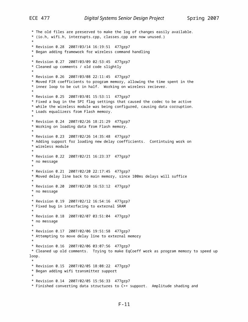
ECE 477 Digital Systems Senior Design Project Spring 2007
UINT Reserved3 : 24; // Unused. For packingUINT Channel : 7;UINT Mode : 1; // 1=Rx 0=Tx
} ConfigData;
#if defined(PING_TEST)static int PowerState = 1;#elsestatic int PowerState = 0;#endif
/****************************************************************************** * Functions *****************************************************************************/
void InitIO(){ // Set the input select lines SRU(FLAG12_O, DAI_PB19_I); SRU(FLAG13_O, DAI_PB20_I); SRU(HIGH, PBEN19_I); SRU(HIGH, PBEN20_I);
sysreg_bit_set(sysreg_FLAGS, FLG12O | FLG13O);
// Set the power up/down lineSRU(FLAG14_O, DAI_PB01_I);SRU(HIGH, PBEN01_I);sysreg_bit_set_nop(sysreg_FLAGS, FLG14O);sysreg_bit_clr_nop(sysreg_FLAGS, FLG14);
}
void SelectInput(int input){ if (input)
{ sysreg_bit_clr(sysreg_FLAGS, FLG13);
sysreg_bit_set(sysreg_FLAGS, FLG12);}else{ sysreg_bit_set(sysreg_FLAGS, FLG13);
sysreg_bit_clr(sysreg_FLAGS, FLG12);}
}
void PowerUp(){ PowerState = 1; sysreg_bit_set_nop(sysreg_FLAGS, FLG14);}
void PowerDown(){ PowerState = 0; sysreg_bit_clr_nop(sysreg_FLAGS, FLG14);}
F-40

ECE 477 Digital Systems Senior Design Project Spring 2007
inline void SetCS(){
sysreg_bit_set_nop(sysreg_FLAGS, FLG10);sysreg_bit_set_nop(sysreg_FLAGS, FLG10);sysreg_bit_set_nop(sysreg_FLAGS, FLG10);
}
inline void ClearCS(){
sysreg_bit_clr_nop(sysreg_FLAGS, FLG10);sysreg_bit_clr_nop(sysreg_FLAGS, FLG10);sysreg_bit_clr_nop(sysreg_FLAGS, FLG10);
}
inline void SetCE(){
sysreg_bit_set_nop(sysreg_FLAGS, FLG11);sysreg_bit_set_nop(sysreg_FLAGS, FLG11);sysreg_bit_set_nop(sysreg_FLAGS, FLG11);
}
inline void ClearCE(){
sysreg_bit_clr_nop(sysreg_FLAGS, FLG11);sysreg_bit_clr_nop(sysreg_FLAGS, FLG11);sysreg_bit_clr_nop(sysreg_FLAGS, FLG11);
}
//#pragma optimize_offvoid InitWireless(int Channel, int RxAddr, int rx){ // Set FLAG10 to PB15 and FLAG11 to PB16 // CS and CE for wireless // Set FLAG2 as input SRU(FLAG10_O, DAI_PB15_I); //CS SRU(FLAG11_O, DAI_PB16_I); //CE SRU(FLAG12_O, DAI_PB04_I); SRU(HIGH, PBEN15_I); SRU(HIGH, PBEN16_I); SRU(HIGH, PBEN04_I); sysreg_bit_set_nop(sysreg_FLAGS, FLG12O | FLG10O | FLG11O); sysreg_bit_set_nop(sysreg_FLAGS, FLG12); ClearCS(); ClearCE(); Wait(10000); // Set up all the data
ConfigData.Mode = rx; // RecievingConfigData.Channel = Channel;ConfigData.RFPwr = 3; // Highest powerConfigData.Xtal = 3; // Presetfor 16 MHz. do not
changeConfigData.DataRate = 0; // 250 kbpsConfigData.CommMode = 1; // ShockBurstConfigData.TwoChannels = 0; // one channel recieveConfigData.CRCEn = 1; // CRC enabledConfigData.CRCSize = 1; // 16-bit CRCConfigData.AddrSize = 16; // 16 bit addrConfigData.Addr1[0] = 0x00; // Address we are listening forConfigData.Addr1[1] = 0x00;
F-41
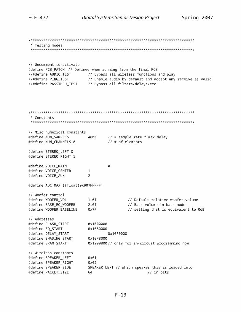
ECE 477 Digital Systems Senior Design Project Spring 2007
ConfigData.Addr1[2] = 0x00;ConfigData.Addr1[3] = (RxAddr & 0xFF00) >> 8; // High byte 0x18;ConfigData.Addr1[4] = (RxAddr & 0x00FF); // Low byte 0xE7;ConfigData.Addr2[0] = 0x00; // Address2. Not usedConfigData.Addr2[1] = 0x00;ConfigData.Addr2[2] = 0x00;ConfigData.Addr2[3] = 0x00;ConfigData.Addr2[4] = 0x00;ConfigData.Data1Size = PACKET_SIZE;ConfigData.Data2Size = 0; // unused
// Wait for SPI to be free// Note: for some reason config baud must be ~50kbps,// while the data baud can be ~0.5Mbpswhile((*pSPIDMAC & SPIDMAS) && !(*pSPISTAT & SPIF)) asm("nop;");*pSPICTL |= TXFLSH | RXFLSH; // Flush registers*pSPISTAT |= TUNF | ROVF; // Clear errors*pSPIDMAC = 0;*pSPIFLG = 0xFF00; // no flags*pSPIBAUD = 10000;*pSPICTL = GM | TIMOD1 | WL8 | SPIMS | SPIEN | MSBF;
ClearCE();SetCS();
Wait(100);
// The wireless doesn't like it when you// send everything all at once. Need to send// it byte by bytefor (int i = 0; i < sizeof(ConfigData); i++){ *pSPICTL |= TXFLSH | RXFLSH; *pSPISTAT |= TUNF | ROVF; sysreg_bit_clr(sysreg_FLAGS, FLG12);
*pTXSPI = *((int*)&ConfigData + i);
Wait(BYTE_DELAY);while (!(*pSPISTAT & SPIF)) asm("nop;");
sysreg_bit_set(sysreg_FLAGS, FLG12);}
*pSPIDMAC = 0;*pSPICTL |= TXFLSH | RXFLSH;*pSPISTAT |= TUNF | ROVF;
Wait(100);
// exit config mode and set for recievingClearCS();SetCE();
}
int rxcnt = 0;
//#pragma optimize_offCReceivePacket* ReadWireless(){ sysreg_bit_clr_nop(sysreg_FLAGS, FLG12); // clock data in
F-42

ECE 477 Digital Systems Senior Design Project Spring 2007
//RecievePacket packet; int data[2] = {0,0};
// Look for vaild data. This will time out after 0.1 ms int i; for (i = 0; i < 100; i++) { if(sysreg_bit_tst(sysreg_FLAGS, FLG2)) break; Wait(1); } if (i == 100) // Timed out return 0;
rxcnt++; Wait(1000); *pSPICTL |= TXFLSH | RXFLSH; *pSPISTAT |= TUNF | ROVF; *pSPIDMAC = 0;
*pSPIFLG = 0xFF00; // no flags*pSPIBAUD = 200; // 0.5 Mbps*pSPICTL = TIMOD2 | WL32 | SPIMS | SPIEN | MSBF;
*pIISPI = (int)data;*pIMSPI = 1;*pCSPI = sizeof(data);*pSPIDMAC = SPIDEN | SPIRCV;
Wait(10000);
// Strobe CEsysreg_bit_clr(sysreg_FLAGS,FLG11);Wait(1000);sysreg_bit_set(sysreg_FLAGS,FLG11);Wait(100);
sysreg_bit_set_nop(sysreg_FLAGS, FLG12);
return ExtractPacket(data);}
F-43
ECE 477 Digital Systems Senior Design Project Spring 2007
File: system.cpp
/****************************************************************************** * Title: * Version: $Revision: 1.12 $ * Filename: $RCSfile: system.cpp,v $ * Author(s): Benjamin Fogle $Author: 477grp7 $ * Created: 1/16/2007 * * Purpose: Contains initialization code and helper functions * * Update history: * $Log: system.cpp,v $ * Revision 1.12 2007/04/24 01:39:53 477grp7 * Cleaned up code, moved some functions to more logical places (e.g., Wait()) * and removed obsolete declarations. * * Revision 1.11 2007/04/23 15:43:57 477grp7 * no message * * Revision 1.10 2007/04/22 18:58:39 477grp7 * no message * * Revision 1.9 2007/04/19 01:34:21 477grp7 * fixed bug in PCB_PATCH preprocessor logic. * * Revision 1.8 2007/04/18 23:54:25 477grp7 * Added support for multiple 'voices' with different sets of shading/delays. * Added PCB_PATCH and AUDIO_TEST defines to make testing easier * * Revision 1.7 2007/04/18 01:23:41 477grp7 * Finishing wireless commands and also modifying the steering routine for * multiple sets of delays on one channel. * * Revision 1.6 2007/04/12 18:46:55 477grp7 * no message * * Revision 1.5 2007/04/11 20:11:12 477grp7 * Major update to command processing/packet interpretation. Was going * to optimize wireless initialization routine, but wireless was acting very very * strange. * * Revision 1.4 2007/04/11 02:28:52 477grp7 * Working on wireless commands. Cleaning up code a little * * Revision 1.3 2007/04/11 00:52:49 477grp7 * no message * * Revision 1.2 2007/04/08 23:02:40 477grp7 * Got wireless working finally. * * Revision 1.1 2007/03/28 13:53:00 477grp7 * no message * * Revision 1.0 2007/03/25 16:45:58 477grp7 * Made major revisions to the structure of the project. It is now organized * more closely according to funtion. (All audio related routines are in * audio.cpp, and all wireless command routines are in commands.cpp, etc.) * More work has been done on the framework for the command routine. * The old files are preserved to make the log of changes easily available. * (io.h, wifi.h, interrupts.cpp, classes.cpp are now unused.) *
F-44

ECE 477 Digital Systems Senior Design Project Spring 2007
* Revision 0.0 2007/01/17 00:22:05 477grp7 * Initial project creation * * *****************************************************************************/
#include <def21262.h>#include <cdef21262.h>#include <21262.h>
#include <SRU.h>#include <signal.h>#include <sysreg.h>
#include "DSP.h"#include "ad1835.h"#include "commands.h"#include "audio.h"#include "system.h"
/****************************************************************************** * Helper function declarations *****************************************************************************/
void OnWaitTimer(int sig); // For the Wait() function
/****************************************************************************** * Global variables (static linkage) *****************************************************************************/
static volatile int WaitTimerFlag = 0;
/****************************************************************************** * Functions *****************************************************************************/
void OnWaitTimer(int){ WaitTimerFlag = 0;}
void Wait(int us){ WaitTimerFlag = 1; timer_off(); interrupts(SIG_TMZ, OnWaitTimer); timer_set(us * 200, us * 200); timer_on(); while(WaitTimerFlag); timer_off();
F-45

ECE 477 Digital Systems Senior Design Project Spring 2007
}
void Init(){ // Interrupts initially disabled InitIO(); InitSystem(); // Power off, etc.
Wait(10000); // 10ms startup time from power on for devices (wireless)InitWireless(RX_CHANNEL, SPEAKER_ADDR, 1); // Initially receiving
InitAudio();}
void InitSystem(){ interrupts(SIG_TMZ, OnWaitTimer); // For wait function // Set initial system state PowerDown(); DisableAudio(); SelectInput(0); SetVolume(0); // Initially mute LoadSteering(0); LoadEq(0);}
F-46

ECE 477 Digital Systems Senior Design Project Spring 2007
Flash Programmer Software Listing (Modified Analog Example Code)
File: ppflash.h
/////////////////////////////////////////////////////////////////////////////////////////NAME: ppflash.h (AMD Parallel Flash Programmer)//DATE: 9/18/03//PURPOSE: contains the definitions and declarations for use across the project files////////////////////////////////////////////////////////////////////////////////////////#ifndef _PPFLASH_H_#define _PPFLASH_H_
//Include the ADSP-21262 Definition file#include <def21262.h>#include <cdef21262.h>
//LED address on the ADSP-21262 Ezkit Lite#define LED_ADDRESS 0x1400000#define FLASH_START 0x1000000
//Sector Size for the AMD Am29LV081B#define SECTOR_SIZE 0x10000
//Declarations of buffers and subroutines used between filesextern int ppInterruptFlag;
void blockWrite(int *, int *, int);
void flashReset(int *);void sectorErase(int *, int);void chipErase(int *);void programBlock(int *, int *, int);void verifyBlock(int *, int *, int);
void writeToPP(int *, int *, int);int readFromPP(int *);int pollFlash(int *);void writeToLEDs(int);void ppInterruptHandler(int);
void WriteByte(int* addr, int data);int ReadByte(int* addr);#endif
F-47

ECE 477 Digital Systems Senior Design Project Spring 2007
File: main.c
/////////////////////////////////////////////////////////////////////////////////////////NAME: main.c (AMD Parallel Flash Programmer)//DATE: 9/18/03//PURPOSE: Program the Parallel Flash for the ADSP-21262 Ezkit////USAGE: This file contains the main code for programming the PP flash on the// ADSP-21262 Ezkit lite.//// If more than one file is to be programmed, either include all files in the// same buffer (for contiguous location), or make sure that the files will not// occupy any common 64K sectors in the flash, as programming the subsequent// buffers will erase parts of the previously programmed buffers.//// For the AMD Am29LV081B the sectors occupy the following byte addresses:// Sector Address Range// SA0 0x00000 - 0x0FFFF// SA1 0x10000 - 0x1FFFF// SA2 0x20000 - 0x2FFFF// SA3 0x30000 - 0x3FFFF// SA4 0x40000 - 0x4FFFF// SA5 0x50000 - 0x5FFFF// SA6 0x60000 - 0x6FFFF// SA7 0x70000 - 0x7FFFF// SA8 0x80000 - 0x8FFFF// SA9 0x90000 - 0x9FFFF// SA10 0xA0000 - 0xAFFFF// SA11 0xB0000 - 0xBFFFF// SA12 0xC0000 - 0xCFFFF// SA13 0xD0000 - 0xDFFFF// SA14 0xE0000 - 0xEFFFF// SA15 0xF0000 - 0xFFFFF////////////////////////////////////////////////////////////////////////////////////////////#include "ppflash.h"#include <signal.h>
//Declare the destination address in the flash of the file#define LDR_START_ADDR 0x1000000
#define FLASH_START 0x1000000#define EQ_START 0x1080000#define DELAYS_START 0x10F0000 // good enough for 15 divisions h & v#define SHADING_START 0x10F8000#define SRAM_START 0x1200000 // only for in-circuit programming now
//Declare the width of the data in the file to determine the number of bytes//Change this declaration in the LDF file also for correct packing.#define FILE_DATA_WIDTH 32
//Declare a semaphore variable to use in the parallel port interruptint ppInterruptFlag = 0;
//Declare a variable in external memory to hold the file data to program#pragma section("seg_ext", DMAONLY)int ldr_source[] = { //#include "input.ldr" #include "..\DSP\Debug\DSP.ldr"
F-48

ECE 477 Digital Systems Senior Design Project Spring 2007
};
// Load the equalizers #pragma section("seg_coeff", DMAONLY)float coeff_data[] = { #include "EqPreset0.csv"
};
// Load the delays#pragma section("seg_delays", DMAONLY)int delays[] = { #include "Delay0.csv" , #include "Delay1.csv" , #include "Delay2.csv" , #include "Delay3.csv" , #include "Delay4.csv" , #include "Delay5.csv" , #include "Delay6.csv" , #include "Delay7.csv" , #include "Delay0.csv" , #include "Delay0.csv" , #include "Delay0.csv" , #include "Delay0.csv" , #include "Delay0.csv" , #include "Delay0.csv" , #include "Delay0.csv" , #include "Delay0.csv"
};
#pragma section("seg_fade", DMAONLY)float fades[] = { #include "Fade0.csv" , #include "Fade1.csv" , #include "Fade2.csv" , #include "Fade3.csv" , #include "Fade4.csv" , #include "Fade5.csv" , #include "Fade6.csv" , #include "Fade7.csv"
F-49

ECE 477 Digital Systems Senior Design Project Spring 2007
, #include "Fade0.csv" , #include "Fade0.csv" , #include "Fade0.csv" , #include "Fade0.csv" , #include "Fade0.csv" , #include "Fade0.csv" , #include "Fade0.csv" , #include "Fade0.csv"
};
//Main routine - add calls to blockWrite for each buffer holding file datavoid main(){ *pPPCTL &= ~(PPEN|PPDEN); //Set up the interrupt for the parallel port interrupt(SIG_PP,ppInterruptHandler); //Workaround for C Runtime problem (fixed with patch released 10/03/2003) interrupt(SIG_SP1, SIG_IGN);
flashReset((int*)FLASH_START); chipErase((int *) LDR_START_ADDR); blockWrite(ldr_source,(int *) LDR_START_ADDR,sizeof(ldr_source)*FILE_DATA_WIDTH/8); blockWrite((int*)coeff_data, (int*)EQ_START, sizeof(coeff_data)*FILE_DATA_WIDTH/8); blockWrite((int*)delays, (int*)DELAYS_START, sizeof(delays)*FILE_DATA_WIDTH/8); blockWrite((int*)fades, (int*)SHADING_START, sizeof(fades)*FILE_DATA_WIDTH/8);}
F-50

ECE 477 Digital Systems Senior Design Project Spring 2007
File: blockWrite.c
/////////////////////////////////////////////////////////////////////////////////////////NAME: blockWrite.c (AMD Parallel Flash Programmer)//DATE: 9/18/03//PURPOSE: Program the Parallel Flash for the ADSP-21262 Ezkit////USAGE: This file calls the subroutines used to program and verify the Flash,// call this routine with the buffer address, destination address, and byte// length from the main program.//////////////////////////////////////////////////////////////////////////////////////////
#include "ppflash.h"//----------------------------------------//BLOCK WRITE SUBROUTINE//Calls all of the Flash subroutines necessary to program the flash//Inputs - buffer_src_addr - address of the buffer holding the 32-bit words to write (pointer)// buffer_dest_addr - address to write to in external memory (pointer)// buffer_length - number of bytes to write.//Returns- nonevoid blockWrite(int *buffer_src_addr,int *buffer_dest_addr,int buffer_length){ int numSectors;
//Reset the state of the flash flashReset(buffer_dest_addr);
//Calculate the number of sectors to be programmed (min = 1)// numSectors = (buffer_length >> 16) + 1; //Erase that number of sectors// sectorErase(buffer_dest_addr,numSectors);
//program the flash with the selected data programBlock(buffer_src_addr,buffer_dest_addr,buffer_length); //verify that the flash was programmed correctly verifyBlock(buffer_src_addr,buffer_dest_addr,buffer_length);
}
F-51

ECE 477 Digital Systems Senior Design Project Spring 2007
File: flashFunctions.c
/////////////////////////////////////////////////////////////////////////////////////////NAME: flashFunctions.c (AMD Parallel Flash Programmer)//DATE: 9/18/03//PURPOSE: Program the Parallel Flash for the ADSP-21262 Ezkit////USAGE: This file contains the subroutines called to program the PP Flash on the// ADSP-21262 Ezkit lite.//////////////////////////////////////////////////////////////////////////////////////////#include "ppflash.h"
//----------------------------------------//RESET THE STATE OF THE FLASH SUBROUTINE//Writes the reset command to the Flash//Inputs - flash_addr - address to write to in external memory (pointer)//Returns- none//Address is only required to make sure that the flash is selected by the address decodervoid flashReset(int *flash_addr){ WriteByte((int*)FLASH_START, 0xF0);}
//----------------------------------------//SECTOR ERASE SUBROUTINE//Erases the selected number of sectors in the flash, starting with the supplied address//Inputs - flash_addr - address to write to in external memory (pointer)// num_sectors - number of 32-bit words to write.//Returns- nonevoid sectorErase(int *flash_addr, int num_sectors){ int wordToWrite[2] = {0x55aa0000, 0x3055aa80}; int i;
//Send the erase command once for each affected sector for(i=0;i<num_sectors;i++) { writeToPP(wordToWrite,(flash_addr+(i*SECTOR_SIZE)),2); //Wait for the flash to finish erasing the sector while((0xFF & readFromPP(flash_addr+(i*SECTOR_SIZE)))!=0xFF) {}; }}
//----------------------------------------//CHIP ERASE SUBROUTINE//Erases the entire chip//Inputs - flash_addr - address to write to in external memory (any)//Returns- nonevoid chipErase(int *flash_addr){ int read; WriteByte((int*)(FLASH_START + 0x00555), 0xAA); WriteByte((int*)(FLASH_START + 0x80AAA), 0x55); WriteByte((int*)(FLASH_START + 0x00555), 0x80); WriteByte((int*)(FLASH_START + 0x00555), 0xAA);
F-52

ECE 477 Digital Systems Senior Design Project Spring 2007
WriteByte((int*)(FLASH_START + 0x80AAA), 0x55); WriteByte((int*)(FLASH_START + 0x00555), 0x10);
do{ read = readFromPP(flash_addr); read &= 0xFF;} while(read != 0xFF);
}
//----------------------------------------//WRITE DATA TO FLASH SUBROUTINE//Programs the specified amount of bytes to the flash.//Inputs - buffer_addr - address of the buffer holding the 32-bit words to write (pointer)// flash_addr - address to write to in external memory (pointer)// buffer_length - number of bytes to write.//Returns- nonevoid programBlock(int *buffer_addr, int *flash_addr, int buffer_length){ int i; int wordToWrite; // last byte will be programmed
int addr = (int)flash_addr;
for(i=0;i<buffer_length;i++) { //construct a single word containing the 24-bit write command and byte to write wordToWrite = readFromPP(buffer_addr+i) & 0xFF;
WriteByte((int*)(FLASH_START + 0x00555), 0xAA); WriteByte((int*)(FLASH_START + 0x80AAA), 0x55); WriteByte((int*)(FLASH_START + 0x00555), 0xA0); WriteByte((int*)(addr + i), wordToWrite);
//Wait for the flash to finish programming pollFlash(flash_addr+i); }}
//----------------------------------------//VERIFY DATA IN FLASH SUBROUTINE//Reads the specified amount of bytes to the flash and compares it to the source buffer.//Inputs - buffer_addr - address of the buffer holding the 32-bit words to write (pointer)// flash_addr - address to write to in external memory (pointer)// buffer_length - number of bytes to write.//Returns- nonevoid verifyBlock(int *buffer_addr, int *flash_addr, int buffer_length){ int i, fromFlash, fromSRAM;
for(i=0;i<buffer_length;i++) { //Read the word from the flash fromFlash = 0xFF & readFromPP(flash_addr+i); //Read the word from SRAM fromSRAM = 0xFF & readFromPP(buffer_addr+i); //Wait here forever if they don't match if(fromFlash != fromSRAM) while(1){};
F-53

ECE 477 Digital Systems Senior Design Project Spring 2007
}}
//----------------------------------------//POLL THE FLASH SUBROUTINE//Reads the flash after it has been programmed to detect when the programming is finished//Inputs - flash_addr - address to write to in external memory (pointer)//Returns- none//Address is only required to make sure that the flash is selected by the address decoderint pollFlash(int *flash_address){ int flash_word[3]; int i;
while(1) { //Read a word from the flash, 32-bits will be read flash_word[0]=readFromPP(flash_address); //Extract the first and second byte into separate words flash_word[1]=(flash_word[0] & 0xFF); flash_word[2]=((flash_word[0]>>8) & 0xFF);
//The flash will toggle bits in the word for each read //When the first and second byte match, the programming is complete if(flash_word[1]==flash_word[2]) break; // Check for program error (bit 5) if ((flash_word[1] & 0x20) || (flash_word[2] & 0x20)) while(1);
}
return flash_word[0];}
//----------------------------------------//WRITE A VALUE TO LEDS SUBROUTINE//Lights the LEDs with the specified pattern//Inputs - flag_value - 8-bit value to display on the 8 LEDs on the ADSP-21262 Ezkit lite//Returns- nonevoid writeToLEDs(int flag_value){ //the MSB of the word will be displayed flag_value <<= 24;
//write this value to the PP at the LED address writeToPP(&flag_value, (int *) LED_ADDRESS, 1);}//----------------------------------------//Parallel Port Interrupt Service Routine//Vector jumped to upon PP interrupt//Returns- Sets a semaphore for the PP Interrupt which the main routines poll for statusvoid ppInterruptHandler(int sig_int){ //Set the PP Interrupt Semaphore ppInterruptFlag = 1;}
F-54

ECE 477 Digital Systems Senior Design Project Spring 2007
File: ppfunctions.h
/////////////////////////////////////////////////////////////////////////////////////////NAME: ppfunctions.c (AMD Parallel Flash Programmer)//DATE: 9/18/03//PURPOSE: Program the Parallel Flash for the ADSP-21262 Ezkit////USAGE: This file contains the subroutines used to access external devices the// via the parallel port.//////////////////////////////////////////////////////////////////////////////////////////#include <sysreg.h>#include "ppflash.h"
//----------------------------------------//WRITE TO PARALLEL PORT SUBROUTINE//Writes the specified amount of words to the parallel port//Inputs - word_out - address of the buffer holding the 32-bit words to write (pointer)// flash_address - address to write to in external memory (pointer)// count32 - number of 32-bit words to write.//Returns- none//This example writes to only one byte at a time. When sending the flash commands, the//only one address is required, so the external modify is set to 0.void writeToPP(int *word_out, int *flash_address, int count32){ //Set up the parallel port for 8-bit writes to external memory *pPPCTL = PPTRAN|PPBHC|PPDUR20;
//Internal DMA address is passed *pIIPP = (int) word_out; //Internal Modify is always 1 *pIMPP = 1; //Internal count is passed *pICPP = count32;
//External DMA Address is passed *pEIPP = (int) flash_address; //External Modify is always 0 *pEMPP = 0; //External count is always 4x internal count (PP only transfers 32-bit words) *pECPP = (count32 * 4);
//Enable the PP for transfer *pPPCTL |= PPDEN|PPEN;
//Wait for the interrupt semaphore to get set while(!ppInterruptFlag){};
//Clear the interrupt semaphore and disable the PP ppInterruptFlag=0; *pPPCTL=0;}
//----------------------------------------//READ FROM PARALLEL PORT SUBROUTINE//Reads the specified amount of words from the parallel port//Inputs - flash_address - external byte address to read from (pointer)//Returns- dataIn - 32-bit word with four copies of the requested byte// Not masked to 1 byte for use with flash polling during programming
F-55

ECE 477 Digital Systems Senior Design Project Spring 2007
// (the PP always reads 4 bytes and it is necessary to view 2 consecutive byte// for reading the status of the Flash)//It is necessary to mask the returned word down to 1 byte (the lowest).int readFromPP(int *flash_address){ //buffer to hold the incoming data int dataIn;
//Set up the parallel port for 8-bit reads from external memory *pPPCTL = PPBHC|PPDUR20;
//Internal address is that of the buffer dataIn *pIIPP = (int) &dataIn; //Internal modify is 0, do not corrupt any other internal memory accidentally *pIMPP = 0; //Only read 1 word at a time *pICPP = 1;
//External address is passed *pEIPP = (int) flash_address; //External count is zero, only reading one byte at a time *pEMPP = 0; //External count is always 4x internal count (PP only transfers 32-bit words) *pECPP = 4;
//Enable the PP for transfer *pPPCTL |= PPDEN|PPEN;
//Wait for the interrupt semaphore to get set while(!ppInterruptFlag){};
//Clear the interrupt semaphore and disable the PP ppInterruptFlag=0; *pPPCTL=0;
return dataIn;}
void WriteByte(int* addr, int data){ *pPPCTL = PPTRAN | PPBHC | PPDUR20; //Internal address is that of the buffer dataIn *pIIPP = (int) &data; //Internal modify is 0, do not corrupt any other internal memory accidentally *pIMPP = 0; //Only read 1 word at a time *pICPP = 1;
//External address is passed *pEIPP = (int) addr; //External count is zero, only reading one byte at a time *pEMPP = 0; //Will this work? *pECPP = 1;
//Enable the PP for transfer *pPPCTL |= PPDEN|PPEN;
//Enable the PP for transfer *pPPCTL |= PPDEN|PPEN;
F-56

ECE 477 Digital Systems Senior Design Project Spring 2007
//Wait for the interrupt semaphore to get set while(!ppInterruptFlag){};
//Clear the interrupt semaphore and disable the PP ppInterruptFlag=0; *pPPCTL=0;
}
int ReadByte(int* addr){ int data; *pPPCTL = PPBHC | PPDUR20; //Internal address is that of the buffer dataIn *pIIPP = (int) &data; //Internal modify is 0, do not corrupt any other internal memory accidentally *pIMPP = 0; //Only read 1 word at a time *pICPP = 1;
//External address is passed *pEIPP = (int) addr; //External count is zero, only reading one byte at a time *pEMPP = 0; //Will this work? *pECPP = 1;
//Enable the PP for transfer *pPPCTL |= PPDEN|PPEN;
//Wait for the interrupt semaphore to get set while(!ppInterruptFlag){};
//Clear the interrupt semaphore and disable the PP ppInterruptFlag=0; *pPPCTL=0; return data;}
F-57
ECE 477 Digital Systems Senior Design Project Spring 2007
File: ADSP-21262_C.LDF
#define FILE_DATA_WIDTH 32ARCHITECTURE(ADSP-21262)
//// ADSP-21262 Memory Map:// ------------------------------------------------// 0x0000 0000 to 0x0003 FFFF IOP Regs// Block0 0x0004 0000 to 0x0004 3FFF Long word (64) Space (1MB RAM)// Block0 0x0004 4000 to 0x0005 7FFF Internal Memory (Reserved 5MB)// Block0 0x0005 8000 to 0x0005 FFFF Long word (64) Space (2MB ROM)
// Block1 0x0006 0000 to 0x0006 3FFF Long word (64) Space (1MB RAM)// Block1 0x0006 4000 to 0x0007 7FFF Internal Memory (Reserved 5MB)// Block1 0x0007 8000 to 0x0007 FFFF Long word (64) Space (2MB ROM)
// Block0 0x0008 0000 to 0x0008 7FFF Normal word (32) Space (1MB RAM)// Block0 0x0008 8000 to 0x000A FFFF Internal Memory (Reserved 5MB)// Block0 0x000B 0000 to 0x000B FFFF Normal word (32) Space (2MB ROM)// ------------------------------------------------// 0x000A 0000 to 0x000A AAAA 48-bit addresses// ------------------------------------------------// Block1 0x000C 0000 to 0x000C 7FFF Normal word (32) Space (1MB RAM)// Block1 0x000C 8000 to 0x000E FFFF Internal Memory (Reserved 5MB)// Block1 0x000F 0000 to 0x000F FFFF Normal word (32) Space (2MB ROM)// ------------------------------------------------// 0x000E 0000 to 0x000E AAAA 48-bit addresses// ------------------------------------------------// Block0 0x0010 0000 to 0x0010 FFFF Short word (16) Space (1MB RAM)// Block0 0x0011 0000 to 0x0015 FFFF Internal Memory (Reserved 5MB)// Block0 0x0011 0000 to 0x0015 FFFF Internal Memory (Reserved 5MB)// Block0 0x0016 0000 to 0x0017 FFFF Short word (16) Space (2MB ROM)
// Block1 0x0018 0000 to 0x0018 FFFF Short word (16) Space (1MB RAM)// Block1 0x0019 0000 to 0x001D FFFF Internal Memory (Reserved 5MB)// Block1 0x001E 0000 to 0x001F FFFF Short word (16) Space (2MB ROM)
// ------------------------------------------------// External memory 0x0100 0000 to 0x02FF FFFF// ------------------------------------------------
// This linker description file allocates:// Internal 256 words of run-time header in memory block 0// 256 words of initialization code in memory block 0// 16K words of C code space in memory block 0// 7K words of C PM data space in memory block 0// 32K words of C DM data space in memory block 1// 8K words of C heap space in memory block 1// 8K words of C stack space in memory block 1
SEARCH_DIR( $ADI_DSP\212xx\lib )
#ifdef _ADI_THREADS#ifdef __ADI_LIBEH__$LIBRARIES = libehmt.dlb, libc26xmt.dlb, libiomt.dlb, libdsp26x.dlb;#else$LIBRARIES = libc26xmt.dlb, libiomt.dlb, libdsp26x.dlb;#endif#else#ifdef __ADI_LIBEH__$LIBRARIES = libeh.dlb, libc26x.dlb, libio.dlb, libdsp26x.dlb;#else
F-58
ECE 477 Digital Systems Senior Design Project Spring 2007
$LIBRARIES = libc26x.dlb, libio.dlb, libdsp26x.dlb;#endif#endif
// Libraries from the command line are included in COMMAND_LINE_OBJECTS.#ifndef EZKIT_MONITOR#ifdef __ADI_LIBEH__#define CRT_HDR 262_hdr_adamagic.doj#else#define CRT_HDR 262_hdr.doj#endif#else#define CRT_HDR 262_hdr_ezkit.doj#endif$OBJECTS = CRT_HDR, $COMMAND_LINE_OBJECTS;
MEMORY{#ifdef __EZKIT_LICENSE_RESTRICTION_SHARC__
// Only 10K available for PM // Use the space unavailable to PM as DM seg_rth { TYPE(PM RAM) START(0x00080000) END(0x000800ff) WIDTH(48) } seg_init { TYPE(PM RAM) START(0x00080100) END(0x000801ff) WIDTH(48) } seg_pmco { TYPE(PM RAM) START(0x00080200) END(0x000825ff) WIDTH(48) } seg_pmda { TYPE(PM RAM) START(0x00083900) END(0x00083DAA) WIDTH(32) } seg_dm32 { TYPE(DM RAM) START(0x00083DAB) END(0x00087FFF) WIDTH(32) }
#else
seg_rth { TYPE(PM RAM) START(0x00080000) END(0x000800ff) WIDTH(48) } seg_init { TYPE(PM RAM) START(0x00080100) END(0x000801ff) WIDTH(48) } seg_int_code { TYPE(PM RAM) START(0x00080200) END(0x00080287) WIDTH(48) } seg_pmco { TYPE(PM RAM) START(0x00080288) END(0x000841ff) WIDTH(48) } seg_pmda { TYPE(PM RAM) START(0x00086300) END(0x00087fff) WIDTH(32) }
#endif
seg_dmda { TYPE(DM RAM) START(0x000c0000) END(0x000c3fff) WIDTH(32) } seg_heap { TYPE(DM RAM) START(0x000c4000) END(0x000c5fff) WIDTH(32) } seg_stak { TYPE(DM RAM) START(0x000c6000) END(0x000c7fff) WIDTH(32) }
seg_ext8_1 { TYPE(DM RAM DMAONLY) START(0x01200000) END(0x0121FFFF) WIDTH(8) } seg_ext8_2 { TYPE(DM RAM DMAONLY) START(0x01220000) END(0x0123FFFF) WIDTH(8) } seg_ext8_3 { TYPE(DM RAM DMAONLY) START(0x01240000) END(0x0125FFFF) WIDTH(8) } seg_ext8_4 { TYPE(DM RAM DMAONLY) START(0x01260000) END(0x0127FFFF) WIDTH(8) }}
PROCESSOR p0{ KEEP( _main,___ctor_NULL_marker,___lib_end_of_heap_descriptions ) LINK_AGAINST( $COMMAND_LINE_LINK_AGAINST) OUTPUT( $COMMAND_LINE_OUTPUT_FILE )
SECTIONS { // .text output section seg_rth { INPUT_SECTIONS( $OBJECTS(seg_rth) $LIBRARIES(seg_rth)) } >seg_rth
F-59

ECE 477 Digital Systems Senior Design Project Spring 2007
seg_init { ldf_seginit_space = . ; INPUT_SECTIONS( $OBJECTS(seg_init) $LIBRARIES(seg_init)) } >seg_init
#ifdef __EZKIT_LICENSE_RESTRICTION_SHARC__
seg_int_code { INPUT_SECTIONS( $OBJECTS(seg_int_code) $LIBRARIES(seg_int_code)) } >seg_pmco
#else seg_int_code { INPUT_SECTIONS( $OBJECTS(seg_int_code) $LIBRARIES(seg_int_code)) } >seg_int_code#endif
seg_pmco { INPUT_SECTIONS( $OBJECTS(seg_pmco) $LIBRARIES(seg_pmco)) } >seg_pmco
seg_pmda { INPUT_SECTIONS( $OBJECTS(seg_pmda) $LIBRARIES(seg_pmda)) } >seg_pmda
seg_dmda { INPUT_SECTIONS( $OBJECTS(seg_dmda) $LIBRARIES(seg_dmda)) } > seg_dmda
#ifdef __EZKIT_LICENSE_RESTRICTION_SHARC__ //When using an EZkit license, only 10K PM words are allowed. The extra space left over in Block 0 which is defined //as PM for full licenses is declared as 32-bit DM data by default for the EZkit license. Make note of this difference //when switching from an EZkit license to a full license while using the default LDF files.
seg_dm32 { INPUT_SECTIONS( $OBJECTS(seg_dm32) $LIBRARIES(seg_dm32) ) } >seg_dm32
#endif
seg_ext8_1 //SHT_NOBITS //For debug purposes, after loading the external segment once, use the SHT_NOBITS //command in the LDF to avoid the lengthy process of initializing external memory via the emulator //as you debug. Be sure to rebuild without SHT_NOBITS after debug or when external data has changed. { INPUT_SECTIONS( $OBJECTS(seg_ext))
#if FILE_DATA_WIDTH==32 /*For loading 32 BIT WORDS into x8 ext. mem:*/
F-60

ECE 477 Digital Systems Senior Design Project Spring 2007
PACKING(5 B0 B0 B0 B4 B5 \ B0 B0 B0 B3 B0 \ B0 B0 B0 B2 B0 \ B0 B0 B0 B1 B0)
#endif
#if FILE_DATA_WIDTH==16 PACKING(5 B0 B1 B2 B4 B5 \ B0 B0 B0 B3 B0) #endif
#if FILE_DATA_WIDTH==8 PACKING(5 B1 B2 B3 B4 B5)
#endif } > seg_ext8_1
seg_ext8_2 //SHT_NOBITS //For debug purposes, after loading the external segment once, use the SHT_NOBITS //command in the LDF to avoid the lengthy process of initializing external memory via the emulator //as you debug. Be sure to rebuild without SHT_NOBITS after debug or when external data has changed. { INPUT_SECTIONS( $OBJECTS(seg_coeff))
#if FILE_DATA_WIDTH==32 /*For loading 32 BIT WORDS into x8 ext. mem:*/ PACKING(5 B0 B0 B0 B4 B5 \ B0 B0 B0 B3 B0 \ B0 B0 B0 B2 B0 \ B0 B0 B0 B1 B0)
#endif
#if FILE_DATA_WIDTH==16 PACKING(5 B0 B1 B2 B4 B5 \ B0 B0 B0 B3 B0) #endif
#if FILE_DATA_WIDTH==8 PACKING(5 B1 B2 B3 B4 B5)
#endif } > seg_ext8_2
seg_ext8_3 //SHT_NOBITS //For debug purposes, after loading the external segment once, use the SHT_NOBITS //command in the LDF to avoid the lengthy process of initializing external memory via the emulator //as you debug. Be sure to rebuild without SHT_NOBITS after debug or when external data has changed. { INPUT_SECTIONS( $OBJECTS(seg_delays))
#if FILE_DATA_WIDTH==32 /*For loading 32 BIT WORDS into x8 ext. mem:*/ PACKING(5 B0 B0 B0 B4 B5 \ B0 B0 B0 B3 B0 \ B0 B0 B0 B2 B0 \ B0 B0 B0 B1 B0)
F-61

ECE 477 Digital Systems Senior Design Project Spring 2007
#endif
#if FILE_DATA_WIDTH==16 PACKING(5 B0 B1 B2 B4 B5 \ B0 B0 B0 B3 B0) #endif
#if FILE_DATA_WIDTH==8 PACKING(5 B1 B2 B3 B4 B5)
#endif } > seg_ext8_3
seg_ext8_4 //SHT_NOBITS //For debug purposes, after loading the external segment once, use the SHT_NOBITS //command in the LDF to avoid the lengthy process of initializing external memory via the emulator //as you debug. Be sure to rebuild without SHT_NOBITS after debug or when external data has changed. { INPUT_SECTIONS( $OBJECTS(seg_fade))
#if FILE_DATA_WIDTH==32 /*For loading 32 BIT WORDS into x8 ext. mem:*/ PACKING(5 B0 B0 B0 B4 B5 \ B0 B0 B0 B3 B0 \ B0 B0 B0 B2 B0 \ B0 B0 B0 B1 B0)
#endif
#if FILE_DATA_WIDTH==16 PACKING(5 B0 B1 B2 B4 B5 \ B0 B0 B0 B3 B0) #endif
#if FILE_DATA_WIDTH==8 PACKING(5 B1 B2 B3 B4 B5)
#endif } > seg_ext8_4
#ifdef __ADI_LIBEH__ .gdt { INPUT_SECTIONS( $OBJECTS(.gdt) $LIBRARIES(.gdt)) } > seg_dmda
.frt { INPUT_SECTIONS( $OBJECTS(.frt) $LIBRARIES(.frt)) } > seg_dmda
.cht { INPUT_SECTIONS( $OBJECTS(.cht) $LIBRARIES(.cht)) } > seg_dmda
.edt { INPUT_SECTIONS( $OBJECTS(.edt) $LIBRARIES(.edt)) } > seg_dmda#endif
F-62
ECE 477 Digital Systems Senior Design Project Spring 2007
stackseg {
// allocate a stack for the application ldf_stack_space = .; ldf_stack_length = MEMORY_SIZEOF(seg_stak); } > seg_stak
heap { // allocate a heap for the application ldf_heap_space = .; ldf_heap_length = MEMORY_SIZEOF(seg_heap); ldf_heap_end = ldf_heap_space + ldf_heap_length - 1; } > seg_heap
}}
F-63

ECE 477 Digital Systems Senior Design Project Spring 2007
File: Delay0.csv
// Comma seperated values, in order// each delay value is in units of 1/48000 s// There are three sets of delays per preset// Omit the comma from the last value4000,4000,4000,4000,0,0,0,0,4000,4000,4000,4000,0,0,0,0,
0,0,0,0,0,0,0,0,0,0,0,0,0,0,0,0,
0,0,0,0,0,0,0,0,0,0,0,0,0,0,0,0
File: Delay1.csv
// Comma seperated values, in order// each delay value is in units of 1/48000 s0,2000,0, 2000, 0, 2000, 0, 2000,0,2000,0, 2000, 0, 2000, 0, 2000,
0,0,0,0,0,0,0,0,0,0,0,0,0,0,0,0,
0,0,0,0,0,0,0,0,0,0,0,0,0,0,0,0
File: Delay2.csv
// Comma seperated values, in order// each delay value is in units of 1/48000 s
// NORMAL MODE24, 24, 24, 24, 24, 24, 24, 24,0,0,0,0,0,0,0,0,
0,0,0,0,0,0,0,0,0,0,0,0,0,0,0,0,
0,0,0,0,0,0,0,0,0,0,0,0,0,0,0,0
File: Delay3.csv
// Comma seperated values, in order// each delay value is in units of 1/48000 s
// PARTY MODE72,38,62,38,62,38,68,72,0,0,0,0,0,0,0,0,
0,0,0,0,0,0,0,0,0,0,0,0,0,0,0,0,
0,0,0,0,0,0,0,0,0,0,0,0,0,0,0,0
F-64

ECE 477 Digital Systems Senior Design Project Spring 2007
File: Delay4.csv
// Comma seperated values, in order// each delay value is in units of 1/48000 s
// WIDE MODE600,120,1200,600,600,240,240,600,600,600,240,120,240,1200,600,600,
0,0,0,0,0,0,0,0,0,0,0,0,0,0,0,0,
0,0,0,0,0,0,0,0,0,0,0,0,0,0,0,0
File: Delay5.csv
// Comma seperated values, in order// each delay value is in units of 1/48000 s
// SURROUND MODE24, 24, 24, 24, 24, 24, 24, 24,58, 91, 58, 29, 91, 58, 29, 58,
0,0,0,0,0,0,0,0,0,0,0,0,0,0,0,0,
0,0,0,0,0,0,0,0,0,0,0,0,0,0,0,0
File: Delay6.csv
// Comma seperated values, in order// each delay value is in units of 1/48000 s
// HORN MODE38,29,29,38,38,48,48,38,0,0,0,0,0,0,0,0,
24, 24, 24, 24, 24, 24, 24, 24,0,0,0,0,0,0,0,0,
38,38,48,29,48,29,38,38,0,0,0,0,0,0,0,0
File: Delay7.csv
// Comma seperated values, in order// each delay value is in units of 1/48000 s
// DEMO MODE120,240,120,48,24,120,48,120,0,0,0,0,0,0,0,0,
0,0,0,0,0,0,0,0,0,0,0,0,0,0,0,0,
0,0,0,0,0,0,0,0,0,0,0,0,0,0,0,0
F-65

ECE 477 Digital Systems Senior Design Project Spring 2007
File: EqPreset0.csv
// 0 -- Flat1.0, 0.0, 0.0,0.0, 0.0,
1.0, 0.0, 0.0,0.0, 0.0,
// 1 -- Rock// Peak EQ. 600Hz, -4dB, Q=0.50.966813, -1.814529, 0.853332,1.814529, -0.820145,
// High shelf, 2800Hz, 4dB, Q=0.7071.494255, -2.305152, 0.940330,1.430569, -0.560002,
// 2 -- Pop// Peak EQ. 500Hz, 3dB, Q=0.51.021526, -1.891579, 0.874115,1.891579, -0.895641,
// High shelf, 1600Hz, -2dB, Q=0.7070.807921, -1.363999, 0.590344,1.721610, -0.755875,
// 3 -- Bass -- Just turn up the subwoofer1.0, 0.0, 0.0,0.0, 0.0,
1.0, 0.0, 0.0,0.0, 0.0,
// 4 -- Vocal// Peak EQ, 1000Hz, 2dB, Q=0.51.026992, -1.776169, 0.764516,1.776169, -0.791508,
// High shelf, 3000Hz, 1dB, Q=0.51.100781, -1.488160, 0.502965,1.320039, -0.435625,
// 5 -- Jazz// Peak EQ, 500Hz, 3dB, Q=0.7071.015460, -1.920926, 0.909591,1.920926, -0.925051,
// High shelf, 4000Hz, 3dB, Q=0.51.313024, -1.589500, 0.481048,1.095407, -0.299979,
// 6 -- 1.067750, -1.625324, 0.603796,1.625324, -0.671546,
1.0, 0.0, 0.0,0.0, 0.0,
// 7 -- 1.067750, -1.625324, 0.603796,1.625324, -0.671546,
F-66

ECE 477 Digital Systems Senior Design Project Spring 2007
1.0, 0.0, 0.0,0.0, 0.0,
// 8 -- 1.067750, -1.625324, 0.603796,1.625324, -0.671546,
1.0, 0.0, 0.0,0.0, 0.0,
// 9 -- 1.067750, -1.625324, 0.603796,1.625324, -0.671546,
1.0, 0.0, 0.0,0.0, 0.0,
// 10 -- 1.067750, -1.625324, 0.603796,1.625324, -0.671546,
1.0, 0.0, 0.0,0.0, 0.0,
// 11 -- 0.000168, 0.000337, 0.000168,1.962960, -0.963633,
1.0, 0.0, 0.0,0.0, 0.0,
// 12 -- 0.000168, 0.000337, 0.000168,1.962960, -0.963633,
1.0, 0.0, 0.0,0.0, 0.0,
// 13 -- 0.000168, 0.000337, 0.000168,1.962960, -0.963633,
1.0, 0.0, 0.0,0.0, 0.0,
// 14 -- 0.000168, 0.000337, 0.000168,1.962960, -0.963633,
1.0, 0.0, 0.0,0.0, 0.0,
// 15 -- (last preset)0.000168, 0.000337, 0.000168,1.962960, -0.963633,
1.0, 0.0, 0.0,0.0, 0.0,
// 16 -- Correction1.0, 0.0, 0.0,0.0, 0.0,
F-67

ECE 477 Digital Systems Senior Design Project Spring 2007
// 17 -- Crossover -- 2nd order HPF: 180Hz, Q=0.7070.983468, -1.966936, 0.983468,1.966663, -0.967210
File: Delay0.csv
// Comma seperated values, in order// valid values are 0.0 to 1.01.0, 1.0, 1.0, 1.0, 1.0, 1.0, 1.0, 1.0,0.0, 0.0, 0.0, 0.0, 0.0, 0.0, 0.0, 0.0,
0.0, 0.0, 0.0, 0.0, 0.0, 0.0, 0.0, 0.0,0.0, 0.0, 0.0, 0.0, 0.0, 0.0, 0.0, 0.0,
0.0, 0.0, 0.0, 0.0, 0.0, 0.0, 0.0, 0.0,0.0, 0.0, 0.0, 0.0, 0.0, 0.0, 0.0, 0.0
File: Delay1.csv
// Comma seperated values, in order// valid values are 0.0 to 1.01.0, 0.0, 0.0, 0.0, 0.0, 0.0, 0.0, 0.0,0.0, 1.0, 0.0, 0.0, 0.0, 0.0, 0.0, 0.0,
0.0, 0.0, 1.0, 0.0, 0.0, 0.0, 0.0, 0.0,0.0, 0.0, 0.0, 1.0, 0.0, 0.0, 0.0, 0.0,
0.0, 0.0, 0.0, 0.0, 1.0, 0.0, 0.0, 0.0,0.0, 0.0, 0.0, 0.0, 0.0, 1.0, 0.0, 0.0
File: Delay2.csv
// Comma seperated values, in order// valid values are 0.0 to 1.0
// NORMAL MODE1.0, 1.0, 1.0, 1.0, 1.0, 1.0, 1.0, 1.0,0.0, 0.0, 0.0, 0.0, 0.0, 0.0, 0.0, 0.0,
0.0, 0.0, 0.0, 0.0, 0.0, 0.0, 0.0, 0.0,0.0, 0.0, 0.0, 0.0, 0.0, 0.0, 0.0, 0.0,
0.0, 0.0, 0.0, 0.0, 0.0, 0.0, 0.0, 0.0,0.0, 0.0, 0.0, 0.0, 0.0, 0.0, 0.0, 0.0
File: Delay3.csv
// Comma seperated values, in order// valid values are 0.0 to 1.0
// PARTY MODE0.8,0.7,0.7,1,1,0.7,0.7,0.8,0.0, 0.0, 0.0, 0.0, 0.0, 0.0, 0.0, 0.0,
0.0, 0.0, 0.0, 0.0, 0.0, 0.0, 0.0, 0.0,0.0, 0.0, 0.0, 0.0, 0.0, 0.0, 0.0, 0.0,
0.0, 0.0, 0.0, 0.0, 0.0, 0.0, 0.0, 0.0,0.0, 0.0, 0.0, 0.0, 0.0, 0.0, 0.0, 0.0
F-68

ECE 477 Digital Systems Senior Design Project Spring 2007
File: Delay4.csv
// Comma seperated values, in order// valid values are 0.0 to 1.0
// WIDE MODE1.0, 1.0, 1.0, 1.0, 1.0, 1.0, 1.0, 1.0,1.0, 1.0, 1.0, 1.0, 1.0, 1.0, 1.0, 1.0,
0.0, 0.0, 0.0, 0.0, 0.0, 0.0, 0.0, 0.0,0.0, 0.0, 0.0, 0.0, 0.0, 0.0, 0.0, 0.0,
0.0, 0.0, 0.0, 0.0, 0.0, 0.0, 0.0, 0.0,0.0, 0.0, 0.0, 0.0, 0.0, 0.0, 0.0, 0.0
File: Delay5.csv
// Comma seperated values, in order// valid values are 0.0 to 1.0
// SURROUND MODE// Should everything be divided by 2?0.5, 0.5, 0.5, 0.5, 0.5, 0.5, 0.5, 0.5, 0.5, 0.5, 0.5, 0.5, 0.5, 0.5, 0.5, 0.5,
0.0, 0.0, 0.0, 0.0, 0.0, 0.0, 0.0, 0.0,0.0, 0.0, 0.0, 0.0, 0.0, 0.0, 0.0, 0.0,
0.0, 0.0, 0.0, 0.0, 0.0, 0.0, 0.0, 0.0,0.0, 0.0, 0.0, 0.0, 0.0, 0.0, 0.0, 0.0
File: Delay6.csv
// Comma seperated values, in order// valid values are 0.0 to 1.0
// Horn MODE// Divide everything by 3?0.95, 0.95, 1.00, 0.95, 0.95, 1.00, 0.95, 0.95, 0.0, 0.0, 0.0, 0.0, 0.0, 0.0, 0.0, 0.0,
0.95, 0.95, 1.00, 0.95, 0.95, 1.00, 0.95, 0.95, 0.0, 0.0, 0.0, 0.0, 0.0, 0.0, 0.0, 0.0,
0.95, 0.95, 1.00, 0.95, 0.95, 1.00, 0.95, 0.95,0.0, 0.0, 0.0, 0.0, 0.0, 0.0, 0.0, 0.0
File: Delay7.csv
// Comma seperated values, in order// valid values are 0.0 to 1.0
// DEMO MODE1.0, 1.0, 1.0, 1.0, 1.0, 1.0, 1.0, 1.0,
0.0, 0.0, 0.0, 0.0, 0.0, 0.0, 0.0, 0.0,
0.0, 0.0, 0.0, 0.0, 0.0, 0.0, 0.0, 0.0
F-69

ECE 477 Digital Systems Senior Design Project Spring 2007
Control Box Software Listing
File: control_box.c
/* Group 7 - Sounds Good. Code To Receive and Decode IR Data from a universal remote controlUses RadioShack 38kHz Infrared Receiver. Model no. 276-640
2.24-07
1-18-07Update by James O'Carroll. Initial creation of file, checks for correct component operation andmicrocontroller<-->computer communication.*/
#include <mega32.h>//#include <stdio.h>#include <delay.h>#include "ctrl_ir_receiver.h"#include "ctrl_defined_screens.h"
#define IR_Input PIND.6#define CLK1 PORTB.7#define MISO PORTB.6 //Microcontroller input#define MOSI PORTB.5 //Microcontroller output#define CLK1_Dir DDRB.7#define MISO_Dir DDRB.6#define MOSI_Dir DDRB.5#define CE PORTD.5#define CS PORTD.3#define DR1 PIND.2#define BLINKER PORTC.0
#define TRANSMITTING 0#define RECEIVING 1#define TRF_SET_CMD 0x01#define TRF_PING_CMD 0x02#define TRF_ACK_CMD 0x03#define TRF_RQS_CMD 0x04#define TRF_SHD_CMD 0x05#define TRF_DLY_CMD 0x06
#ifndef NULL#define NULL 0#endif
void process_ir_signal(unsigned int);int ez_execute(int, int, int, char);char ez_Wait();void place_volume(int);int load_screen(int);int ez_Boot(void);//void menu_beacon(int, int, int Clean_Flag);void menu_beacon(int);//TRF Function Declarationsvoid trf_spi(unsigned char);void trf_time_delay();void boot_shockburst();void trf_set();
F-70

ECE 477 Digital Systems Senior Design Project Spring 2007
void trf_shd();void trf_dly();//TRF Function Declarations Done
//!!!!!!!!!!!!!!!!!IR Receiver Variables!!!!!!!!!!!!!!!!!!!!unsigned char Overflow_Counter;//, IR_Ready; //timer 1 overflow counterunsigned int Pulse_Start, Pulse_End, Total_Rollover, Short_Rollover, Rollover_Time;unsigned int Sync, Received_Bits, Data_Bit, Prev_Data_Bit, Num_Received_Bits;unsigned long Pulse_Length, Check_Length;unsigned long Error_Length;//#################IR Receiver Variables####################
//!!!!!!!!!!!!!!!!!ezVID Variables!!!!!!!!!!!!!!!!!!!!!!!!!!eeprom char Word_Color = 0;eeprom char Word_Weak_Color = 7;eeprom char Screen_Color = 12;int Screen_Num = 0, Previous_Screen_Num = -1;int Menu_Choice_Index = 0, Previous_Menu_Choice_Index = 0;eeprom unsigned int Screen_Volume = 50;//#################ezVID Variables##########################
//!!!!!!!!!!!!!!!!!Speaker Variables!!!!!!!!!!!!!!!!!!!!!!!!eeprom unsigned char Custom_Delay_Flag=0;eeprom unsigned char Custom_Shade_Flag=0;eeprom unsigned int Spkr_E = 0; //Custom equalizer. 1=ignore EQeeprom unsigned int Spkr_C = 0; //Custom steering. 1=ignore steering valueseeprom unsigned int Spkr_P = 1; //Power. 1 = on, 0 = standby modeeeprom unsigned int Spkr_I = 0; //Input Select. 0 = Input A, 1 = Input Beeprom unsigned int Main_Volume = 0x7FFF;eeprom unsigned char Spkr_Focus = 1; //Default to left speakereeprom unsigned char Spkr_L_SH[8] = {0,0,0,0,0,0,0,0};eeprom unsigned char Spkr_R_SH[8] = {0,0,0,0,0,0,0,0};eeprom unsigned char Spkr_IDX = 0; //Alternate value is 0x00010000eeprom unsigned char Spkr_L_DL[8] = {99,99,99,99,99,99,99,99};eeprom unsigned char Spkr_R_DL[8] = {99,99,99,99,99,99,99,99};eeprom unsigned char STR_Preset = 2;eeprom unsigned char EQ_Preset = 0;eeprom unsigned char STR_Message_Redirect = 0;eeprom unsigned char EQ_Message_Redirect = 0;//#################Speaker Variables########################//!!!!!!!!!!!!!!!!!TRF Variables!!!!!!!!!!!!!!!!!!!!unsigned char Send_Sequence = 0;unsigned char Receive_Flag = TRANSMITTING;unsigned int TRF_Count = 0;flash int TRF_Configuration[18] = { 0x00, //B[119:112], 0 bit package for receiver 2 0b01000000, //64 bit package for receiver 1, B[111:104] 0x00, //B[103:96] 0x00, //B[95:88] 0x00, //B[87:80] 0x00, //B[79:72] 0x00, //B[71:64] 0x00, //B[63:56] 0x00, //B[55:48] 0x00, //B[47:40] 0b00011000, //B[39:32] Receiver Address (1) 0b11100111, //B[31:24] Receiver Address (2) 0b01000011, //B[23:18],B[17],B[16] 16 bit address, 2 byte CRC, CRC Enabled 0b01001111, //B[15],B[14],B[13],B[12],B[11],B[10],B[9],B[8] 1-channel receive, ShockBurst //mode, 250 kbs, standard crystal, max output power in transmit mode
F-71

ECE 477 Digital Systems Senior Design Project Spring 2007
0b00000101, //B[7:1], B[0] Frequency channel, receive mode 0b00000100, //B[7:1], B[0] Frequency channel, transmit mode 0xF0, 0b11100111};
unsigned int Packet_ID = 0x03;
//#################TRF Variables####################
interrupt [TIM1_OVF] void timer1_ovf_isr(void) //Timer 1 Overflow Interrupt Service Routine{ ++TRF_Count; ++Overflow_Counter; if ((Sync == 2) && (Overflow_Counter*Rollover_Time > Check_Length)) { Data_Bit = IR_Input; Received_Bits = Received_Bits | Data_Bit; Received_Bits = Received_Bits<<1; ++Num_Received_Bits; if (Data_Bit == 1) TCCR1B = TCCR1B & 0xBF; //Set to trigger on falling edge next else TCCR1B = TCCR1B | 0x40; //Set for rising edge trigger next Sync = 3; } if ((Sync == 2) && (Overflow_Counter*Rollover_Time > Error_Length)) { //Error, this should not happen Sync=0; Received_Bits = 0x03; Num_Received_Bits = 2; } TCNT1 = Short_Rollover; return;} interrupt [TIM1_CAPT] void timer1_capt_isr(void) //Timer 1 Data Received{ if (Sync==0) { Pulse_Start = ICR1; //Save start time for pulse Sync = 1; TCCR1B = TCCR1B | 0x40; //Set for rising edge trigger next } else if (Sync==1) { Pulse_End = ICR1; Sync=2; } else { if (Sync == 3) Sync = 2; } Overflow_Counter = 0;
return;}
int main(void){
F-72

ECE 477 Digital Systems Senior Design Project Spring 2007
int i; UCSRA = 0x00; //UCSRA = 0x00; UCSRB = 0x18; //UCSRB = 0x08 UCSRC = 0x86; //UCSRC = 0x86; UBRRH = 0x00; //UBRRH = 0x00; UBRRL = 53; //Serial Port Setup Complete SPCR = 0x53; //Enable SPI but not interrupt, MSB first, Master Mode, ==0b0101 0011 //CLK Polarity uninverted, measuring at rising edge. #asm //Assembly code to clear SPI interrupt flag in r30, spsr in r30, spdr #endasm DDRC.0 = 1; //Blinking LED DDRD.0 = 0; //Serial RX (ezVID), Input DDRD.1 = 1; //Serial TX (ezVID), Output DDRD.2 = 0; //DR1, transceiver DDRD.3 = 1; //CS DDRD.5 = 1; //CE DDRD.6 = 0; //IR Receiver, Input CLK1_Dir = 1; PORTB.4 = 1; MISO_Dir = 0; //Making MISO an input MOSI_Dir = 1; BLINKER = 1;
//Initialize IR values Pulse_Length = 7400; Check_Length = Pulse_Length/2; Check_Length = 3*Check_Length; Error_Length = 30*Pulse_Length; Sync=0; Total_Rollover = 65536; Rollover_Time = 2000; Short_Rollover = Total_Rollover - Rollover_Time; Received_Bits = 0x03; Num_Received_Bits = 2; Prev_Data_Bit = 0; Data_Bit = 0; TCCR0 = 0x00; //Disable timer 0// TCCR0 = 0x05; //Initialize timer 0, system clock/1024, executing for trf ping TCCR1B=0x01; //Timer 1 input to clock, enable the interrupt. Capture on falling edge. Noise canceller?// TIMSK = 0x24; //Unmask timer 1 overflow and capture interrupts TIMSK = 0x25; //also activate timer 0//Initialize IR values done CS=0; CE=0; delay_ms(200);
// printf("Lets kick it\r"); ez_Boot(); load_screen(0); Screen_Num = 0; boot_shockburst(); #asm("sei") //Enable the global interrupt bit delay_ms(500); load_screen(1); Screen_Num = 1; menu_beacon(0); while(1) {
F-73

ECE 477 Digital Systems Senior Design Project Spring 2007
// if ((TRF_Count > 600) && (Num_Received_Bits == 2)) if (TRF_Count > 5000) { trf_set(); TRF_Count = 0; Sync=0; Received_Bits = 0x03; Num_Received_Bits = 2; } if (Num_Received_Bits == 43) { #asm("cli");// printf("%X received\r", Received_Bits); process_ir_signal(Received_Bits); Sync=0; Received_Bits = 0x03; Num_Received_Bits = 2; #asm("sei"); } } return 0;}
/*********************************************************************************************************************TRF Functions***********************************************/void trf_spi(unsigned char Data){ /* TRF needs a delay between consecutive data transfers. This function is here to make code easier to read and modify. */ SPDR = Data; delay_ms(15); return;}
void trf_time_delay(){ /* TRF needs a delay between settings changes. This function is here to make code easier to read and modify. */ delay_ms(30); return;}/***************************************************************************/void boot_shockburst(){ int i; CS = 1; CE = 0; delay_ms(25); for(i=0;i<14;++i) { SPDR = TRF_Configuration[i]; delay_ms(25); } if (Receive_Flag == RECEIVING) SPDR = TRF_Configuration[14]; else SPDR = TRF_Configuration[15]; delay_ms(25); CS = 0; delay_ms(25); return;
F-74

ECE 477 Digital Systems Senior Design Project Spring 2007
}/***************************************************************************/void trf_set(){ unsigned char Feed_TRF; CS = 0; CE = 1; trf_time_delay(); trf_spi(TRF_Configuration[10]); //Sharc Address pt 1 trf_spi(TRF_Configuration[11]); //Sharc Address pt 2 Feed_TRF = Packet_ID >> 4; trf_spi(Feed_TRF); Feed_TRF = Packet_ID & 0x00FF; Feed_TRF = Feed_TRF << 4; Feed_TRF = Feed_TRF | TRF_SET_CMD; trf_spi(Feed_TRF); trf_spi(0x00); //Junk bits Feed_TRF = 0x00; Feed_TRF = (Feed_TRF | Spkr_E) << 1; Feed_TRF = (Feed_TRF | Spkr_C) << 1; Feed_TRF = (Feed_TRF | Spkr_P) << 1; Feed_TRF = (Feed_TRF | Spkr_I); trf_spi(Feed_TRF); Feed_TRF = 0x00; Feed_TRF = Main_Volume >> 8; trf_spi(Feed_TRF); //Volume, high byte first Feed_TRF = Main_Volume; trf_spi(Feed_TRF); //Volume complete Feed_TRF = 0x00; Feed_TRF = STR_Preset << 4; Feed_TRF = Feed_TRF | EQ_Preset; trf_spi(Feed_TRF); //Don't know what to put for STR and EQ trf_spi(0x00); //Unused bits CE = 0; trf_time_delay(); return;}/***************************************************************************/void trf_dly(){ unsigned char Feed_TRF; CS = 0; CE = 1; trf_time_delay(); trf_spi(TRF_Configuration[10]); //Receiver Addres pt 1 trf_spi(TRF_Configuration[11]); //Receiver Addres pt 2 Feed_TRF = Packet_ID << 8; trf_spi(Feed_TRF); Feed_TRF = 0x00; Feed_TRF = Packet_ID & 0x00FF; Feed_TRF = Feed_TRF << 4; Feed_TRF = Feed_TRF | TRF_DLY_CMD; trf_spi(Feed_TRF); Feed_TRF = 0x00; trf_spi(Spkr_Focus); Feed_TRF = 0x00; if (Spkr_Focus == 1) //Left Speaker { Feed_TRF = Spkr_L_SH[0]; Feed_TRF = Feed_TRF << 3; //5 bits, speaker 0 Feed_TRF = Feed_TRF | (Spkr_L_SH[1] >> 2); //3 bits, speaker 1 trf_spi(Feed_TRF); Feed_TRF = 0x00;
F-75

ECE 477 Digital Systems Senior Design Project Spring 2007
Feed_TRF = Spkr_L_SH[1] << 6; //2 bits, Speaker 1 Feed_TRF = Feed_TRF | (Spkr_L_SH[2] << 1); //Five bits, Speaker 2 Feed_TRF = Feed_TRF | (Spkr_L_SH[3] >> 4); //One bit, Speaker 3 trf_spi(Feed_TRF); Feed_TRF = 0x00; Feed_TRF = (Spkr_L_SH[3] << 3) & 0xF0; //Four bits of speaker 3 Feed_TRF = Feed_TRF | (Spkr_L_SH[4] >> 1); //Four bits of speaker 4 trf_spi(Feed_TRF); Feed_TRF = 0x00; Feed_TRF = Spkr_L_SH[4] << 7; //1 bit of speaker 4 Feed_TRF = Feed_TRF | (Spkr_L_SH[5] << 2); //5 bits of speaker 5 Feed_TRF = Feed_TRF | (Spkr_L_SH[6] >> 3); //2 bits of speaker 6 trf_spi(Feed_TRF); Feed_TRF = 0x00; Feed_TRF = Spkr_L_SH[6] << 5; //3 bits of speaker 6 Feed_TRF = Feed_TRF | Spkr_L_SH[7]; //Speaker 7 trf_spi(Feed_TRF); Feed_TRF = 0x00; } CE = 0; trf_time_delay(); return;}/***************************************************************************/void trf_shd(){ int i; unsigned char Feed_TRF; CS = 0; CE = 1; trf_time_delay(); trf_spi(TRF_Configuration[10]); //Receiver Address pt 1 trf_spi(TRF_Configuration[11]); //Receiver Address pt 2
Feed_TRF = Packet_ID << 8; trf_spi(Feed_TRF); Feed_TRF = 0x00; Feed_TRF = Packet_ID & 0x00FF; Feed_TRF = Feed_TRF << 4; Feed_TRF = Feed_TRF | TRF_SHD_CMD; trf_spi(Feed_TRF); Feed_TRF = 0x00; Feed_TRF = (Spkr_IDX << 4) | Spkr_Focus; trf_spi(Feed_TRF); Feed_TRF = 0x00; if (Spkr_Focus == 1) //Left Speaker { if (Spkr_IDX == 0) for (i=0;i<4;++i) trf_spi(Spkr_L_DL[i]); else for (i=5;i<8;++i) trf_spi(Spkr_L_DL[i]); } else { if (Spkr_IDX == 0) for (i=0;i<4;++i) trf_spi(Spkr_R_SH[i]); else for (i=5;i<8;++i) trf_spi(Spkr_R_DL[i]); } trf_spi(0x00); CE = 0; trf_time_delay(); return;}/****************************************************************************************
F-76
ECE 477 Digital Systems Senior Design Project Spring 2007
*****************************IR Functions************************************************/void process_ir_signal(unsigned int Received_Bits){ int Temp; if (((Received_Bits & 0xF000) == SIGNAL_CODE) || ((Received_Bits & 0xF000) == SIGNAL_CODE_ALT)) {// printf("%X received\r", Received_Bits); Received_Bits = Received_Bits & 0x0FFF; switch(Received_Bits) { case POWER: break; case CHAN_DOWN: Previous_Menu_Choice_Index = Menu_Choice_Index; if (Menu_Choice_Index == Screen[Screen_Num].Num_Messages -1) Menu_Choice_Index = 0; else ++Menu_Choice_Index; menu_beacon(0); break; case CHAN_UP: Previous_Menu_Choice_Index = Menu_Choice_Index; if (Menu_Choice_Index == 0) Menu_Choice_Index = Screen[Screen_Num].Num_Messages-1; else --Menu_Choice_Index; menu_beacon(0); break; case VOLUME_RIGHT:// if (Screen_Volume != 99) ++Screen_Volume; if (Screen_Num == 1) place_volume(0); if (Screen_Volume != 96) Screen_Volume += 4; if (Screen_Num == 1) place_volume(1); Main_Volume = Screen_Volume * 660; break; case VOLUME_LEFT:// if (Screen_Volume != 0) --Screen_Volume; if (Screen_Num == 1) place_volume(0); if (Screen_Volume != 0) Screen_Volume -= 4; if (Screen_Num == 1) place_volume(1); Main_Volume = Screen_Volume * 660; break; case OK_MUTE: if (Screen[Screen_Num].Message[Menu_Choice_Index].Command == 1) //Change screen { Temp = Menu_Choice_Index; Previous_Menu_Choice_Index = Menu_Choice_Index; Menu_Choice_Index = 0; Screen_Num = Screen[Screen_Num].Message[Temp].Command_Mod; menu_beacon(1); load_screen(Screen_Num); } else if (Screen[Screen_Num].Message[Menu_Choice_Index].Command == 2) //Set delay mode { STR_Preset = Screen[Screen_Num].Message[Menu_Choice_Index].Command_Mod; STR_Message_Redirect = Menu_Choice_Index;
Temp = Menu_Choice_Index; Previous_Menu_Choice_Index = Menu_Choice_Index; Menu_Choice_Index = 0;
F-77

ECE 477 Digital Systems Senior Design Project Spring 2007
Screen_Num = 1; menu_beacon(1); load_screen(Screen_Num); } else if (Screen[Screen_Num].Message[Menu_Choice_Index].Command == 3) //Set equalization mode { EQ_Preset = Screen[Screen_Num].Message[Menu_Choice_Index].Command_Mod; EQ_Message_Redirect = Menu_Choice_Index;
Temp = Menu_Choice_Index; Previous_Menu_Choice_Index = Menu_Choice_Index; Menu_Choice_Index = 0; Screen_Num = 1; menu_beacon(1); load_screen(Screen_Num); } else if (Screen[Screen_Num].Message[Menu_Choice_Index].Command == 4) //Reset { STR_Preset = 2; STR_Message_Redirect = 0; EQ_Preset = 0; EQ_Message_Redirect = 0; Temp = Menu_Choice_Index; Previous_Menu_Choice_Index = Menu_Choice_Index; Menu_Choice_Index = 0; Screen_Num = 1; menu_beacon(1); load_screen(Screen_Num); } break; case ZERO: load_screen(0); break; case ONE: load_screen(1); break; case TWO: load_screen(2); break; case THREE: load_screen(3); break; case FOUR: load_screen(4); break; case FIVE: load_screen(5); break; case SIX: load_screen(6); break; case SEVEN: load_screen(7); break; case EIGHT: break; case NINE: break; } }}/***************************************************************************/
F-78

ECE 477 Digital Systems Senior Design Project Spring 2007
int load_screen(int Screen_Num){ int i; // int j; i = 0; if (Screen_Num != 1) place_volume(0); if (Previous_Screen_Num != -1) { while (i<Screen[Previous_Screen_Num].Num_Messages) { ez_execute(Previous_Screen_Num, i, 0, 'C'); //Clean away previous words ++i; } }
for (i=0;i<Num_Symbols;++i) { if (Symbols[i].Screen == Previous_Screen_Num) ez_execute(Screen_Num,i,0,'U'); //Clean away previous symbols }
Previous_Screen_Num = Screen_Num; i=0; while (i<Screen[Screen_Num].Num_Messages) { ez_execute(Screen_Num, i, 1, 'C'); //Add new messages ++i; } for (i=0;i<Num_Symbols;++i) { if (Symbols[i].Screen == Previous_Screen_Num) ez_execute(Screen_Num,i,1,'U'); //Add new symbols } //Add Current input and volume iff on screen 1 if (Screen_Num == 1) { place_volume(1); } return 0;}
char ez_Wait(){ char Status; while ((UCSRA & 0x80) == 0) {} Status = UDR; return Status;} int ez_execute(int Screen_Num, int Message_Num, int Clean_Flag, char Order)//Clean Flag = 1 means normal operation{ int i=0;// int Status; int Temp_x; int Temp_Letter; int Quit_Flag = 0; Temp_Letter = 65;
if (Order == 'C') { Temp_x = Screen[Screen_Num].Message[Message_Num].x; while (Quit_Flag == 0)
F-79

ECE 477 Digital Systems Senior Design Project Spring 2007
{ UDR = Order; ez_Wait(); if (Screen[Screen_Num].Message[Message_Num].Word[0] == '[') //Main menu, Delay setting { Temp_Letter = Screen[4].Message[EQ_Message_Redirect].Word[i]; if (Screen[4].Message[EQ_Message_Redirect].Word[i] == NULL) Quit_Flag = 1; } else if (Screen[Screen_Num].Message[Message_Num].Word[0] == ']') //Main menu, Delay setting { Temp_Letter = Screen[2].Message[STR_Message_Redirect].Word[i]; if (Screen[2].Message[STR_Message_Redirect].Word[i] == NULL) Quit_Flag = 1; } else { Temp_Letter = Screen[Screen_Num].Message[Message_Num].Word[i]; if (Screen[Screen_Num].Message[Message_Num].Word[i] == NULL) Quit_Flag = 1; } ++i; if ((64 < Temp_Letter) && (Temp_Letter < 91)) UDR = Temp_Letter - 64; // Temp_Letter is a letter if ((57 < Temp_Letter) && (Temp_Letter < 64)) UDR = Temp_Letter - 11; if ((47 < Temp_Letter) && (Temp_Letter < 58)) UDR = Temp_Letter + 5; // Temp_Letter is a number if ((32 < Temp_Letter) && (Temp_Letter < 46)) UDR = Temp_Letter - 1; // Temp_Letter is a punctuation mark
ez_Wait(); if (Clean_Flag == 0) UDR = Screen_Color; else UDR = Word_Color; ez_Wait(); UDR = Temp_x; Temp_x = Temp_x + 8; UDR = Screen[Screen_Num].Message[Message_Num].y; ez_Wait(); ez_Wait(); ez_Wait(); } i = 0; } else if (Order == 'U') { UDR = Order; ez_Wait(); UDR = Symbols[Message_Num].Index; ez_Wait(); if (Clean_Flag == 0) UDR = Screen_Color; else UDR = Word_Color; ez_Wait(); UDR = Symbols[Message_Num].x; ez_Wait(); UDR = Symbols[Message_Num].y; ez_Wait(); ez_Wait(); } return 0;}
int ez_Boot(void){
F-80

ECE 477 Digital Systems Senior Design Project Spring 2007
int i; int j; char Status; for(i=0;i<2;++i) { UDR = 'R'; Status = ez_Wait(); Status = ez_Wait(); //Screen has been reset } UDR = 'B'; Status = ez_Wait(); UDR = 12; Status = ez_Wait(); ez_Wait(); //Screen Color has been changed
for(i=0;i<Num_Symbols;++i) { UDR = 'A'; ez_Wait(); UDR = i; ez_Wait(); for(j=0;j<14;++j) { UDR = Symbols[i].Symbol[j]; ez_Wait(); } ez_Wait();// ez_Wait(); } return 0;}
void menu_beacon(int Change_Screen_Check){ UDR = 'C'; ez_Wait(); UDR = 41; //Asterix ez_Wait(); UDR = Screen_Color; ez_Wait(); if (Change_Screen_Check == 1) { UDR = Screen[Previous_Screen_Num].Message[Previous_Menu_Choice_Index].x-8;; ez_Wait(); UDR = Screen[Previous_Screen_Num].Message[Previous_Menu_Choice_Index].y; } else { UDR = Screen[Screen_Num].Message[Previous_Menu_Choice_Index].x-8;; ez_Wait(); UDR = Screen[Screen_Num].Message[Previous_Menu_Choice_Index].y; } ez_Wait(); ez_Wait();
UDR = 'C'; ez_Wait(); UDR = 41; //Asterix ez_Wait(); UDR = Word_Color; ez_Wait(); UDR = Screen[Screen_Num].Message[Menu_Choice_Index].x-8;
F-81

ECE 477 Digital Systems Senior Design Project Spring 2007
ez_Wait(); UDR = Screen[Screen_Num].Message[Menu_Choice_Index].y; ez_Wait(); ez_Wait(); return;}
void place_volume(int Clean_Flag) //Clean Flag = 1 means normal operation{ int Temp_Vol; UDR = 'C'; ez_Wait(); if ((Screen_Volume >= 0) && (Screen_Volume < 10)) { UDR = (int)'0' + 5; Temp_Vol = Screen_Volume; } else if ((Screen_Volume >= 10) && (Screen_Volume < 20)) { UDR = (int)'1' + 5; Temp_Vol = Screen_Volume - 10; } else if ((Screen_Volume >= 20) && (Screen_Volume < 30)) { UDR = (int)'2' + 5; Temp_Vol = Screen_Volume - 20; } else if ((Screen_Volume >= 30) && (Screen_Volume < 40)) { UDR = (int)'3' + 5; Temp_Vol = Screen_Volume - 30; } else if ((Screen_Volume >= 40) && (Screen_Volume < 50)) { UDR = (int)'4' + 5; Temp_Vol = Screen_Volume - 40; } else if ((Screen_Volume >= 50) && (Screen_Volume < 60)) { UDR = (int)'5' + 5; Temp_Vol = Screen_Volume - 50; } else if ((Screen_Volume >= 60) && (Screen_Volume < 70)) { UDR = (int)'6' + 5; Temp_Vol = Screen_Volume - 60; } else if ((Screen_Volume >= 70) && (Screen_Volume < 80)) { UDR = (int)'7' + 5; Temp_Vol = Screen_Volume - 70; } else if ((Screen_Volume >= 80) && (Screen_Volume < 90)) { UDR = (int)'8' + 5; Temp_Vol = Screen_Volume - 80; } else if ((Screen_Volume >= 90) && (Screen_Volume < 100)) { UDR = (int)'9' + 5; Temp_Vol = Screen_Volume - 90; } ez_Wait();
F-82

ECE 477 Digital Systems Senior Design Project Spring 2007
if (Clean_Flag == 1) UDR = Word_Color; else UDR = Screen_Color; ez_Wait(); UDR = 42; ez_Wait(); UDR = 193; ez_Wait(); ez_Wait(); //First number placed
UDR = 'C'; ez_Wait(); UDR = Temp_Vol + 53; ez_Wait(); if (Clean_Flag == 1) UDR = Word_Color; else UDR = Screen_Color; ez_Wait(); UDR = 50; ez_Wait(); UDR = 193; ez_Wait(); ez_Wait(); //Second number placed
}
File: ctrl_defined_screens.h
/*flash struct ez_Message{ char Word[16]; char x; char y;// char Code;};*/
flash struct ez_Message{ char Word[16]; char x; char y; char Command; char Command_Mod;};
flash struct ez_Screen{ int Num_Messages; struct ez_Message Message[8];};
flash struct ez_user_defined_char{ char Symbol[14]; char x; char y; char Screen; char Index;};
const int Num_Symbols = 32;
F-83
ECE 477 Digital Systems Senior Design Project Spring 2007
const int Num_Screens = 8;
flash struct ez_user_defined_char Symbols[28] = {{{0,0,0,0,0,0,0,15,15,15,15,15,15,15} ,80,50,0,0}, //SG logo, S1{{255,255,255,255,255,255,255,192,192,192,192,192,192,192},88,50,0,1}, //SG logo, S2{{15,15,15,15,15,15,15,15,15,15,0,0,0,0} ,80,64,0,2}, //SG logo, S3{{192,192,192,192,192,192,192,192,192,192,255,255,255,255},88,64,0,3}, //SG logo, S4{{255,255,255,255,255,255,255,15,15,15,15,15,15,15} ,96,50,0,4}, //SG logo, S5{{0,0,0,0,0,0,0,192,192,192,192,192,192,192} ,104,50,0,5}, //SG logo, S6{{15,0,0,0,0,0,0,0,0,0,255,255,255,255} ,96,64,0,6}, //SG logo, S7{{192,0,0,0,0,0,0,0,0,0,0,0,0,0} ,104,64,0,7}, //SG logo, S8{{0,0,0,0,0,0,0,0,0,0,0,0,0,15} ,80,78,0,8}, //SG logo, S9{{255,255,255,255,0,0,0,0,0,0,0,0,0,192} ,88,78,0,9}, //SG logo, S10{{15,15,15,15,15,15,15,0,0,0,0,0,0,0} ,80,92,0,10}, //SG logo, S11{{192,192,192,192,192,192,192,255,255,255,255,255,255,255},88,92,0,11}, //SG logo, S12{{255,255,255,255,15,15,15,15,15,15,15,15,15,15} ,96,78,0,12}, //SG logo, S13{{0,0,0,0,192,192,192,192,192,192,192,192,192,192} ,104,78,0,13}, //SG logo, S14{{15,15,15,15,15,15,15,255,255,255,255,255,255,255} ,96,92,0,14}, //SG logo, S15{{192,192,192,192,192,192,192,0,0,0,0,0,0,0} ,104,92,0,15}, //SG logo, S16{{0,0,0,0,0,0,0,15,15,15,15,15,15,15} ,87,90,0,16}, //SG logo, G1{{255,255,255,255,255,255,255,192,192,192,192,192,192,192},95,90,0,17}, //SG logo, G2{{15,15,15,15,15,15,15,15,15,15,15,15,15,15} ,87,104,0,18}, //SG logo, G3{{192,192,192,192,192,192,192,192,192,192,192,192,192,192},95,104,0,19}, //SG logo, G4{{255,255,255,255,255,255,255,15,15,15,15,15,15,15} ,103,90,0,20}, //SG logo, G5{{0,0,0,0,0,0,0,192,192,192,192,192,192,192} ,111,90,0,21}, //SG logo, G6{{0,0,0,0,0,0,0,255,255,255,255,255,255,255} ,103,104,0,22}, //SG logo, G7{{0,0,0,0,0,0,0,192,192,192,192,192,192,192} ,111,104,0,23}, //SG logo, G8{{15,15,15,15,15,15,15,15,15,15,15,15,15,15} ,87,118,0,24}, //SG logo, G9{{192,192,192,192,192,192,192,192,192,192,192,192,192,192},95,118,0,25}, //SG logo, G10{{15,15,15,15,15,15,15,0,0,0,0,0,0,0} ,87,132,0,26}, //SG logo, G11{{192,192,192,192,192,192,192,255,255,255,255,255,255,255},95,132,0,27}, //SG logo, G12{{255,255,255,255,15,15,15,15,15,15,15,15,15,15} ,103,118,0,28}, //SG logo, G13{{192,192,192,192,192,192,192,192,192,192,192,192,192,192},111,118,0,29}, //SG logo, G14{{15,15,15,15,15,15,15,255,255,255,255,255,255,255} ,103,132,0,30}, //SG logo, G15{{192,192,192,192,192,192,192,0,0,0,0,0,0,0} ,111,132,0,31} //SG logo, G16};
//Want right edge of words to end at 82, X axisflash struct ez_Screen Screen[8] = {{4,{{"DIGITAL",24,180,0,0 }, {"STEERABLE", 88,180,0,0 }, {"SOUND", 40,195,0,0 }, {"SYSTEM",88,195,0,0 },{"DS3",72,210,0,0 },{"VOID",72,130,0,0 },{"VOID",72,130,0,0 },{"VOID",72,130,0,0 }}},{6,{{"+", 10,175,0,0 }, {"VOL:",10,193,0,0 },{"-", 10,210,0,0 }, {"]",106,140,1,2}, {"[",138,175,1,4 }, {"SETTINGS",114,210,1,5 },{"INPUT",10,140,0,0 }, {"VOID",72,130,0,0 }}},{7,{{"NORMAL",10,140,2,2 }, {"WIDE", 10,175,2,4 }, {"SURROUND", 10,210,2,5 }, {"MAIN",146,60,1,1 },{"DIGI HORN",106,140,2,6},{"PARTY",138,175,2,3 },{"CUSTOM",130,210,2,0},{"VOID",72,130,0,0 }}}, //Delay settings{8,{{"PREVIOUS",10,140,0,0 }, {"+", 10,175,0,0 }, {"-", 10,210,0,0 }, {"VOLUME", 10,193,0,0 },{"NEXT",146,140 },{"+",170,175,0,0 },{"-",170,210,0,0 },{"DELAY",138,193,0,0}}},
F-84

ECE 477 Digital Systems Senior Design Project Spring 2007
{7,{{"FLAT",10,140,3,0 }, {"ROCK", 10,175,3,1 }, {"POP", 10,210,3,2 }, {"MAIN",146,60,1,1 },{"BASS",146,140,3,3},{"VOCAL",138,175,3,4 },{"JAZZ",146,210,3,5},{"VOID",72,130,0,0 }}}, //EQ settings{4,{{"DEMONSTRATION",10,175,0,0}, {"SUBWOOFER VOL",10,210,1,6}, {"BALANCE",122,190,1,7 },{"RESET",138,225,4,0 },{"VOID",72,130,0,0 },{"VOID",72,130,0,0 },{"VOID",72,130,0,0 },{"VOID",72,130,0,0 }}},{6,{{"LEFT VOL",10,140,0,0}, {"RIGHT VOL",100,140,0,0 }, {"+", 10,175,0,0 }, {"-",10,210,0,0 },{"+",170,175,0,0 },{"-",170,210,0,0 },{"VOID",72,210,0,0 },{"VOID",72,130,0,0 }}},{6,{{"LEFT VOL",10,140,0,0}, {"RIGHT VOL",100,140,0,0 }, {"+", 10,175,0,0 }, {"-",10,210,0,0 },{"+",170,175,0,0 },{"-",170,210,0,0 },{"VOID",72,210,0,0 },{"VOID",72,130,0,0 }}}};
File: ctrl_ir_receiver.h
#define SIGNAL_CODE 0xE000#define SIGNAL_CODE_ALT 0xC000#define POWER 0x0032#define CHAN_UP 0x0082#define CHAN_DOWN 0x0086#define VOLUME_RIGHT 0x0042#define VOLUME_LEFT 0x0046#define OK_MUTE 0x0036#define ZERO 0x0002#define ONE 0x0006#define TWO 0x000A#define THREE 0x000E#define FOUR 0x0012#define FIVE 0x0016#define SIX 0x001A#define SEVEN 0x001E#define EIGHT 0x0022#define NINE 0x0026
F-85

ECE 477 Final Report Spring 2006
Appendix G: FMECA Worksheet
Failure No.
Failure Mode Possible Causes Failure Effects Method of Detection
Criticality Remarks
A1 No voltage output Circuit short, damaged or nonfunctioning component, disconnected power, fuse burnout
Tower operation and communication failure
Observation, control box will cite communication error
High Possible excess heat
A2 Excessive voltage output
Broken resistor short, high voltage input
Speaker tower failure, component damage.
Observation, possible physical effects, communication with control box error
High Likely excess heat, component damage. Fuse lowers possibility of long-term behavior.
A3 Noisy voltage Broken/incorrect capacitor/resistor. Noisy voltage input
Irregular behavior, sound quality problems
Observation. Low
Functional Block A: Power Supply
G-1

ECE 477 Final Report Spring 2006
Failure No.
Failure Mode Possible Causes Failure Effects Method of Detection
Criticality Remarks
B1 No sound output Power failure, software error or reset, processor damage
No sound output Observation Low
B2 Control Box communication failure
Damage to wireless transceiver/connection. Tower out of wireless range with control box. Wireless interference
Inability to change output settings.
Observation, control box error message
High Can be dangerous if audio is at maximum level.
B3 Irregular sound output
Software/DSP algorithm error
Changing or strange sound output
Observation High Potential to increase audio output radically
Functional Block B: DSPFailure
No.Failure Mode Possible Causes Failure Effects Method of
DetectionCriticality Remarks
C1 No sound output Destroyed/nonfunctioning digital amplifier. Broken circuit
No sound output Observation High Possible excessive heat source
C2 Irregular sound output
Shorted circuit, amplifier working incorrectly
Changing or strange sound output
Observation High Potential to increase audio output radically, excess heat
G-2

ECE 477 Final Report Spring 2006
Functional Block C: Audio OutputFailure
No.Failure Mode Possible Causes Failure Effects Method of
DetectionCriticality Remarks
D1 No signal output Destroyed/nonfunctioning component. Broken circuit, poorly connected audio source
No sound output Observation High Possible excessive heat source
D2 Irregular signal output
Damaged resistor/capacitor, short circuit
Changing or strange sound output
Observation High Potential to increase audio output radically, excess heat
Functional Block D: Audio InputFailure
No.Failure Mode Possible Causes Failure Effects Method of
DetectionCriticality Remarks
E1 Speaker tower Communication failure
Damage to wireless transceiver/connection. Tower out of wireless range with control box. Wireless interference
Inability to change settings
Observation, control box error message
High Can be dangerous if audio is at maximum level.
E2 Video output failure
Software error, power loss or short
No video output Observation High Potential short or break, excessive heat source
G-3
ECE 477 Final Report Spring 2006
E3 IR sensor failure Software error, broken or damaged RC circuit
Inability to change settings with remote control
Observation Low
Functional Block E: User interface circuit
G-4