ee360: multiuser wireless systems and networks lecture 1 outline course details course syllabus...
TRANSCRIPT

EE360: Multiuser Wireless Systems and Networks
Lecture 1 OutlineCourse DetailsCourse SyllabusCourse Overview
Future Wireless NetworksMultiuser Channels (Broadcast/MAC
Channels)Spectral Reuse and Cellular SystemsAd-Hoc, Sensor, and Cognitive Radio
NetworksBandwidth Sharing in Multiuser
ChannelsOverview of Multiuser Channel
CapacityCapacity of Broadcast Channels

Course Information*
People
Instructor: Andrea Goldsmith, andrea@ee, Packard 371, 5-6932, OHs: MW after class and by appt.
TA: Mainak Chowdhury, Email: [email protected] OHs: around HWs. Possibly around paper discussions organized via Piazza.
Class Administrator: Pat Oshiro, poshiro@stanford, Packard 365, 3-2681.
*See web or handout for more details
Course InformationNuts and Bolts
Prerequisites: EE359 Course Time and Location: MW 9:30-10:45.
Y2E2 101. Class Homepage:
www.stanford.edu/class/ee360 Contains all required reading, handouts,
announcements, HWs, etc.
Class Mailing List: ee360win01314-students (automatic for on-campus registered students). Guest list: send TA email to sign up
Tentative Grading Policy: 10% Class participation 10% Class presentation 15% Homeworks 15% Paper summaries 50% Project (10% prop, 15% progress report, 25%
final report+poster)

Grade Components Class participation
Read the required reading before lecture/discuss in class
Class presentationPresent a paper related to one of the course
topicsHW 0: Choose 3 possible high-impact
papers, each on a different syllabus topic, by Jan. 13. Include a paragraph for each describing main idea(s), why interesting/high impact
Presentations begin Jan. 22.
HW assignmentsTwo assignments from book or other
problems
Paper summariesTwo 2-4 page summaries of several articlesEach should be on a different topic from the
syllabus

Term project on anything related to multiuser wireless
Analysis, simulation and/or experiment Must contain some original research 2 can collaborate if project merits collaboration
(scope, synergy)
Must set up website for project Will post proposal, progress report, and final report
to website Project proposal due Jan. 27 at midnight
1-2 page proposal with detailed description of project plan
Comments Feb 3, revised project proposal due Feb 10.
Progress report: due Feb. 24 at midnight
2-3 page report with introduction of problem being investigated, system description, progress to date, statement of remaining work
Poster presentations last week of classes (We 3/13, Th 3/14?)
Final report due March 17 at midnight
Project
See website for details

Tentative Syllabus
Weeks 1-2: Multiuser systems (Chapters 13.4 and 14, additional papers)
Weeks 3-4: Cellular systems (Chapter 15, additional papers)
Weeks 5-6: Ad hoc wireless networks (Chapter 16, additional papers)
Week 7-8: Cognitive radio networks (papers)
Week 8-9: Sensor networks (papers) Weeks 10: Additional Topics. Course
Summary

Future Wireless Networks
Ubiquitous Communication Among People and Devices
Next-generation CellularWireless Internet AccessWireless MultimediaSensor Networks Smart Homes/SpacesAutomated HighwaysIn-Body NetworksAll this and more …

Multiuser Channels:Uplink and Downlink
Downlink (Broadcast Channel or BC): One Transmitter to Many Receivers.
Uplink (Multiple Access Channel or MAC): Many Transmitters to One Receiver.
R1
R2
R3
x h1(t)x h21(t)
x
h3(t)
x h22(t)
Challenge: How to share the channel among multiuser users
Uplink and Downlink typically duplexed in time or frequency

Spectral ReuseDue to its scarcity, spectrum
is reused
BS
In licensed bands
Cellular, Wimax Wifi, BT, UWB,…
and unlicensed bands
Reuse introduces interference

Interference: Friend or Foe?
If treated as noise: Foe
If decodable (MUD): Neither friend nor foe
If exploited via cooperation and cognition: Friend (especially in a network setting)
IN
PSNR
Increases BER
Reduces capacity

Cellular Systems Reuse channels to maximize
capacity 1G: Analog systems, large frequency reuse, large cells,
uniform standard 2G: Digital systems, less reuse (1 for CDMA), smaller
cells, multiple standards, evolved to support voice and data (IS-54, IS-95, GSM)
3G: Digital systems, WCDMA competing with GSM evolution.
4G: OFDM/MIMO 5G: ???
BASESTATION
MTSO

Rethinking “Cells” in Cellular
Traditional cellular design “interference-limited”MIMO/multiuser detection can remove interferenceCooperating BSs form a MIMO array: what is a cell?Relays change cell shape and boundariesDistributed antennas move BS towards cell boundarySmall cells create a cell within a cell Mobile cooperation via relaying, virtual MIMO, analog
network coding.
SmallCell
Relay
DAS
Coop MIMO
How should cellularsystems be designed?
Will gains in practice bebig or incremental; incapacity or coverage?

ce
Ad-Hoc/Mesh Networks
Outdoor Mesh
Indoor Mesh

Ad-Hoc Networks
Peer-to-peer communications No backbone infrastructure or centralized
control Routing can be multihop. Topology is dynamic. Fully connected with different link SINRs Open questions
Fundamental capacity Optimal routing Resource allocation (power, rate, spectrum,
etc.)

Design Issues
Ad-hoc networks provide a flexible network infrastructure for many emerging applications.
The capacity of such networks is generally unknown.
Transmission, access, and routing strategies for ad-hoc networks are generally ad-hoc.
Crosslayer design critical and very challenging.
Energy constraints impose interesting design tradeoffs for communication and networking.

Cognition Radios
Cognitive radios can support new wireless users in existing crowded spectrumWithout degrading performance of existing
users
Utilize advanced communication and signal processing techniquesCoupled with novel spectrum allocation
policies
Technology could Revolutionize the way spectrum is
allocated worldwide Provide sufficient bandwidth to support
higher quality and higher data rate products and services

Cognitive Radio Paradigms
UnderlayCognitive radios constrained to
cause minimal interference to noncognitive radios
InterweaveCognitive radios find and exploit
spectral holes to avoid interfering with noncognitive radios
OverlayCognitive radios overhear and
enhance noncognitive radio transmissions
Knowledge
andComplexi
ty

Underlay Systems Cognitive radios determine the
interference their transmission causes to noncognitive nodesTransmit if interference below a given
threshold
The interference constraint may be metVia wideband signalling to maintain
interference below the noise floor (spread spectrum or UWB)
Via multiple antennas and beamforming
NCR
IP
NCRCR CR
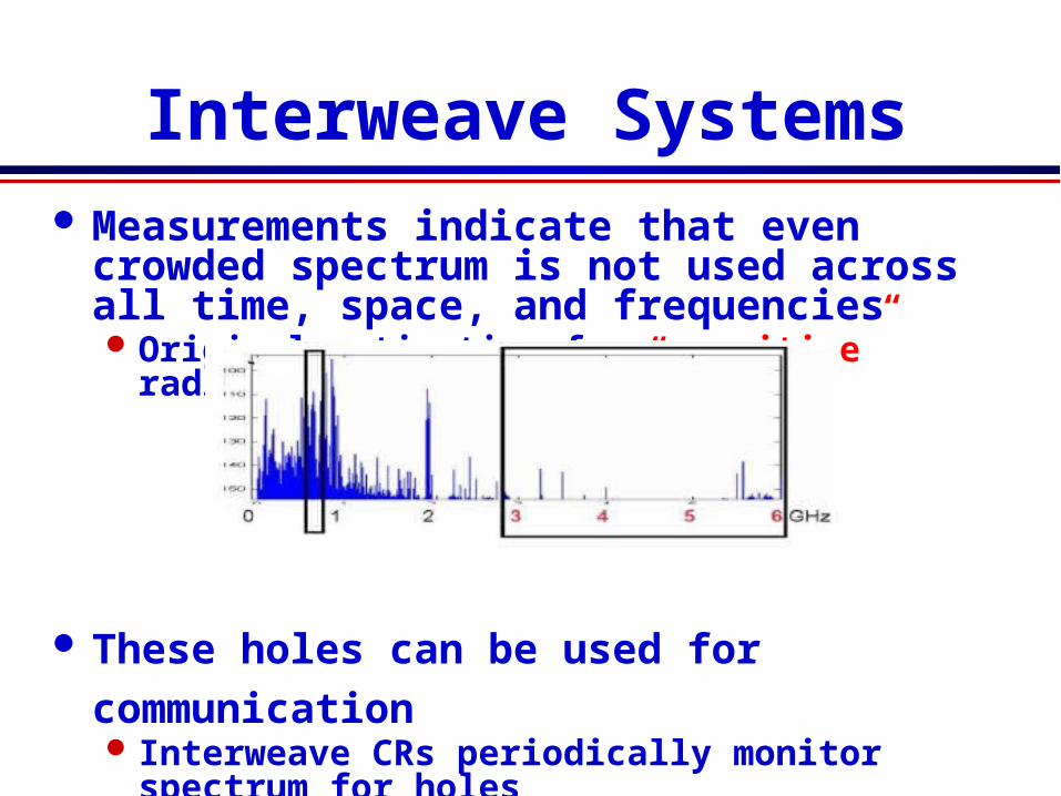
Interweave Systems Measurements indicate that even
crowded spectrum is not used across all time, space, and frequenciesOriginal motivation for “cognitive” radios
(Mitola’00)
These holes can be used for communicationInterweave CRs periodically monitor
spectrum for holesHole location must be agreed upon between
TX and RXHole is then used for opportunistic
communication with minimal interference to noncognitive users

Overlay Systems
Cognitive user has knowledge of other user’s message and/or encoding strategyUsed to help noncognitive
transmissionUsed to presubtract noncognitive
interferenceRX1
RX2NCR
CR

Wireless Sensor and “Green” Networks
Energy (transmit and processing) is driving constraint Data flows to centralized location (joint compression) Low per-node rates but tens to thousands of nodes Intelligence is in the network rather than in the devices Similar ideas can be used to re-architect systems and
networks to be green
• Smart homes/buildings• Smart structures• Search and rescue• Homeland security• Event detection• Battlefield surveillance

Energy-Constrained Nodes
Each node can only send a finite number of bits.Transmit energy minimized by maximizing
bit timeCircuit energy consumption increases with
bit timeIntroduces a delay versus energy tradeoff
for each bit Short-range networks must consider
transmit, circuit, and processing energy.Sophisticated techniques not necessarily
energy-efficient. Sleep modes save energy but complicate
networking.
Changes everything about the network design:Bit allocation must be optimized across all
protocols.Delay vs. throughput vs. node/network
lifetime tradeoffs.Optimization of node cooperation.

Green” Cellular Networks
Minimize energy at both the mobile and base station viaNew Infrastuctures: cell size, BS placement,
DAS, Picos, relaysNew Protocols: Cell Zooming, Coop MIMO,
RRM, Scheduling, Sleeping, RelayingLow-Power (Green) Radios: Radio
Architectures, Modulation, coding, MIMO
Pico/Femto
Relay
DAS
Coop MIMO
How should cellularsystems be redesignedfor minimum energy?
Research indicates thatsignicant savings is possible

Crosslayer Design in Wireless Networks
ApplicationNetwork
AccessLinkHardwareTradeoffs at all layers of the protocol stack are optimized with respect to
end-to-end performanceThis performance is dictated by the
application

Multiuser Channels

Uplink and Downlink
Downlink (Broadcast Channel or BC): One Transmitter to Many Receivers.
Uplink (Multiple Access Channel or MAC): Many Transmitters to One Receiver.
R1
R2
R3
x h1(t)x h21(t)
x
h3(t)
x h22(t)
Challenge: How to share the channel among multiuser users
Uplink and Downlink typically duplexed in time or frequency

RANDOM ACCESS TECHNIQUES
7C29822.038-Cimini-9/97
Random Access
Dedicated channels wasteful for dataUse statistical multiplexing
TechniquesALOHA and slotted ALOHACarrier sensing
Collision detection or avoidanceReservation protocols (similar to
deterministic access)
Retransmissions used for corrupted data
Poor throughput and delay characteristics under heavy loading

ALOHA
Data is packetized Retransmit
When packets collide
Pure ALOHA send packet whenever data is available a collision occurs for any partial overlap of packets
Slotted ALOHA send packets during predefined timeslots avoids partial overlap of packets
Comments Inefficient for heavily loaded systems Capture effect (packets with high SINR decoded)
improves efficiency
.40
.30
.20
.10
0 0.5 1.0 1.5 2.0 3.0
G (Attempts per Packet TIme)
Th
rou
gh
pu
t p
er P
acke
t T
ime)
Pure Aloha
Slotted Aloha

RTS
Channel sensed before transmission To determine if it is occupied
More efficient than ALOHA fewer retransmissions
Carrier sensing is often combined with collision detection in wired networks (e.g. Ethernet)
not possible in a radio environment
Collision avoidance (busy tone, RTS/CTS) can be used
Carrier Sense Techniques
Wired Network
Busy Tone
Wireless Network
CTS

Deterministic Bandwidth Sharing
Frequency Division
Time Division
Code DivisionMultiuser Detection
Space Division (MIMO) Hybrid Schemes
Code Space
Time
Frequency Code Space
Time
FrequencyCode Space
Time
Frequency
What is optimal?
Look to Shannon.

Multiple Access SS
Interference between users mitigated by code cross correlation
In downlink, signal and interference have same received power
In uplink, “close” users drown out “far” users (near-far problem)
)()2cos(5.5.)()(5.5.
))(2cos()2cos()()()()2(cos)()()(ˆ
1221
0
212211
122
0
222
111
c
T
cc
cccc
T
cc
fdddttstsdd
dttftftstststftststx
b
b
a
a
Multiuser Detection In all CDMA systems and in
TD/FD/CD cellular systems, users interfere with each other.
In most of these systems the interference is treated as noise.Systems become interference-limitedOften uses complex mechanisms to
minimize impact of interference (power control, smart antennas, etc.)
Multiuser detection exploits the fact that the structure of the interference is knownInterference can be detected and
subtracted outBetter have a darn good estimate of the
interference

Ideal Multiuser Detection
Signal 1 Demod
IterativeMultiuserDetection
Signal 2Demod
- =Signal 1
- =
Signal 2
Why Not Ubiquitous Today? Power and A/D Precision
A/D
A/D
A/D
A/D

Multiuser Shannon Capacity
Fundamental Limit on Data Rates
Main drivers of channel capacity Bandwidth and received SINR Channel model (fading, ISI) Channel knowledge and how it is used Number of antennas at TX and RX
Duality connects capacity regions of uplink and downlink
Capacity: The set of simultaneously achievable rates {R1,…,Rn}with arbitrarily small probability of error
R1R2
R3
R1
R2
R3

Broadcast Channel Capacity
Region in AWGN
ModelOne transmitter, two receivers with
spectral noise density n1, n2: n1<n2.Transmitter has average power Pand total
bandwidth B.
Single User Capacity: Maximum achievable rate with asymptotically
small Pe
Set of achievable rates includes (C1,0) and
(0,C2), obtained by allocating all resources
to one user.
Bn
PBC
ii 1log

Rate Region: Time Division
Time Division (Constant Power)Fraction of time t allocated to each user
is varied
Time Division (Variable Power)Fraction of time t and power si allocated
to each user is varied
10;)1(, 2211 CRCRU
.10,)1(
;1log)1(,1log
21
2
22
1
11
P
BnBR
BnBRU

Rate Region: Frequency Division
Frequency DivisionBandwidth Bi and power Si allocated to each
user is varied.
BBBPPP
Bn
PBR
Bn
PBR
2121
22
222
11
111
,
;1log,1logU
Equivalent to TD for Bi=tiB and Pi=tisi.

Superposition Coding
Best user decodes fine pointsWorse user decodes coarse points

Code Division Superposition Coding
Coding strategy allows better user to cancel out interference from worse user.
DS spread spectrum with spreading gain G and cross correlation r12= r21 =G:
By concavity of the log function, G=1 maximizes the rate region.
DS without interference cancellation
PPP
SBn
PBR
Bn
PBR 21
12
22
1
11 ;1log,1logU
PPP
GSGBn
P
G
BR
GBn
P
G
BR 21
12
22
1
11 ;
//1log,
/1logU
PPPGPGBn
P
G
BR
GPGBn
P
G
BR 21
12
22
21
11 ;
//1log,
//1logU


Broadcast and MAC Fading Channels
Goal: Maximize the rate region {R1,…,Rn}, subject to some minimum rateconstraints, by dynamic allocation of power, rate, and coding/decoding.
WirelessGateway
WiredNetwork
Broadcast: One Transmitter to Many Receivers.
Multiple Access: Many Transmitters to One Receiver.
R1
R2R3
x g1(t)
x g2(t)x g3(t)
Assume transmit power constraint and perfect TX and RX CSI

Fading Capacity Definitions
Ergodic (Shannon) capacity: maximum long-term rates averaged over the fading process.
Shannon capacity applied directly to fading channels.
Delay depends on channel variations. Transmission rate varies with channel quality.
Zero-outage (delay-limited*) capacity: maximum rate that can be maintained in all fading states.
Delay independent of channel variations. Constant transmission rate – much power needed
for deep fading.
Outage capacity: maximum rate that can be maintained in all nonoutage fading states.
Constant transmission rate during nonoutage Outage avoids power penalty in deep fades
*Hanly/Tse, IT, 11/98

Two-User Fading Broadcast Channel
+
+X[i]
n1[i]
n2[i]
Y1[i]
Y2[i]
x
x
h1[i]
h2[i]
+
+X[i]
n1[i]=n1[i]/h1[i]
n2[i]=n2[i]/h2[i]
Y1[i]
Y2[i]
At each time i:n={n1[i],n2[i]}

Ergodic Capacity Region*
Capacity region: ,where
The power constraint implies
Superposition coding and successive decoding achieve capacityBest user in each state decoded last
Power and rate adapted using multiuser water-filling: power allocated based on noise levels and user priorities
)()( PFP CPCergodic
}1,][1)(
)(1log)(
1
MjnnnPBn
nPBERC M
iijij
jnj
P
PnPEM
jjn
1
)(
*Li/Goldsmith, IT, 3/01

Zero-Outage Capacity Region*
The set of rate vectors that can be maintained for all channel states under power constraint P
Capacity region defined implicitly relative to power:For a given rate vector R and fading
state n we find the minimum power Pmin(R,n) that supports R.
RCzero(P) if En[Pmin(R,n)] P
)()( PFP CPC Nnzero
MjnnnPBn
nPBRC M
iijij
jj 1,
][1)(
)(1log)(
1
P
*Li and Goldsmith, IT, 3/01

Outage Capacity Region Two different assumptions about outage:
All users turned off simultaneously (common outage Pr)
Users turned off independently (outage probability vector Pr)
Outage capacity region implicitly defined from the minimum outage probability associated with a given rate
Common outage: given (R,n), use threshold policyIf Pmin(R,n)>s* declare an outage,
otherwise assign this power to state n.
Power constraint dictates s* :
Outage probability:
),(min
*),(: min nRPEPsnRPn
*),(min:
)(snRPn
npPr

Independent Outage
With independent outage cannot use the threshold approach:Any subset of users can be active in each
fading state.
Power allocation must determine how much power to allocate to each state and which users are on in that state.
Optimal power allocation maximizes the reward for transmitting to a given subset of users for each fading stateReward based on user priorities and outage
probabilities.An iterative technique is used to maximize
this reward.Solution is a generalized threshold-decision
rule.
Minimum-Rate Capacity Region
Combines ergodic and zero-outage capacity:Minimum rate vector maintained in all
fading states.Average rate in excess of the minimum
is maximized.
Delay-constrained data transmitted at the minimum rate at all times.
Channel variation exploited by transmitting other data at the maximum excess average rate.

Minimum Rate Constraints
Define minimum rates R* = (R*1,…,R*
M): These rates must be maintained in all
fading states.
For a given channel state n:
R* must be in zero-outage capacity region Allocate excess power to maximize excess
ergodic rate The smaller R*, the bigger the min-rate
capacity region
nRnRnnnPBn
nPBnR jjM
iijij
jj
*
1
)(,][1)(
)(1log)(

Comparison of Capacity Regions
For R* far from Czero boundary, Cmin-rate
Cergodic
For R* close to Czero boundary, Cmin-rate
CzeroR*

Min-Rate Capacity Region:
Large Deviation in User Channels
Symmetric channel with 40 dB difference in noises in each fading state (user 1 is 40 dB stronger in 1 state, and vice versa).
P = 10 mW, B = 100 KHz
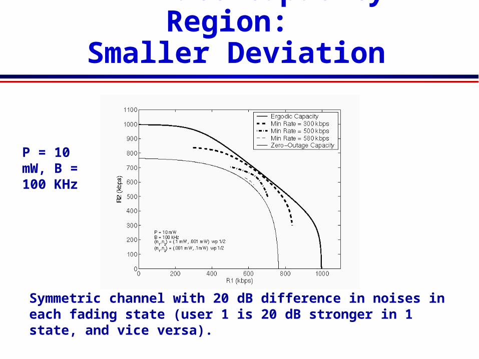
Min-Rate Capacity Region:
Smaller Deviation
Symmetric channel with 20 dB difference in noises in each fading state (user 1 is 20 dB stronger in 1 state, and vice versa).
P = 10 mW, B = 100 KHz

Broadcast Channels with ISI
ISI introduces memory into the channel
The optimal coding strategy decomposes the channel into parallel broadcast channelsSuperposition coding is applied to each
subchannel.
Power must be optimized across subchannels and between users in each subchannel.

Broadcast Channel Model
Both H1 and H2 are finite IR filters of
length m. The w1k and w2k are correlated noise
samples. For 1<k<n, we call this channel the n-
block discrete Gaussian broadcast channel (n-DGBC).
The channel capacity region is C=(R1,R2).
w1k
H1(w)
H2(w)w2k
xk
y h x wk ii
m
kk i1 11
1
y h x wk ii
m
kk i2 21
2

Circular Channel Model
Define the zero padded filters as:
The n-Block Circular Gaussian Broadcast Channel (n-CGBC) is defined based on circular convolution:
{~
} ( ,..., , ,..., )h h hi in
m 1 1 0 0
~ ~(( ))
y h x w x h wk ii
n
k i i kk i1 10
1
1 1 1
~ ~(( ))
y h x w x h wk ii
n
k i i kk i2 20
1
2 2 2
0<k<n
where ((.)) denotes addition modulo n.

Equivalent Channel Model
Taking DFTs of both sides yields
Dividing by H and using additional properties of the DFT yields
~ ~Y H X Wj j j j1 1 1 ~ ~Y H X Wj j j j2 2 2
0<j<n
~
Y X Vj j j1 1
Y X Vj j j2 2
where {V1j} and {V2j} are independent zero-mean Gaussian random variables with lj l ljn N j n H l2 22 1 2 ( ( / )/|
~| , , .
0<j<n

Parallel Channel Model
+
+X1
V11
V21
Y11
Y21
+
+Xn
V1n
V2n
Y1n
Y2n
Ni(f)/Hi(f)
f
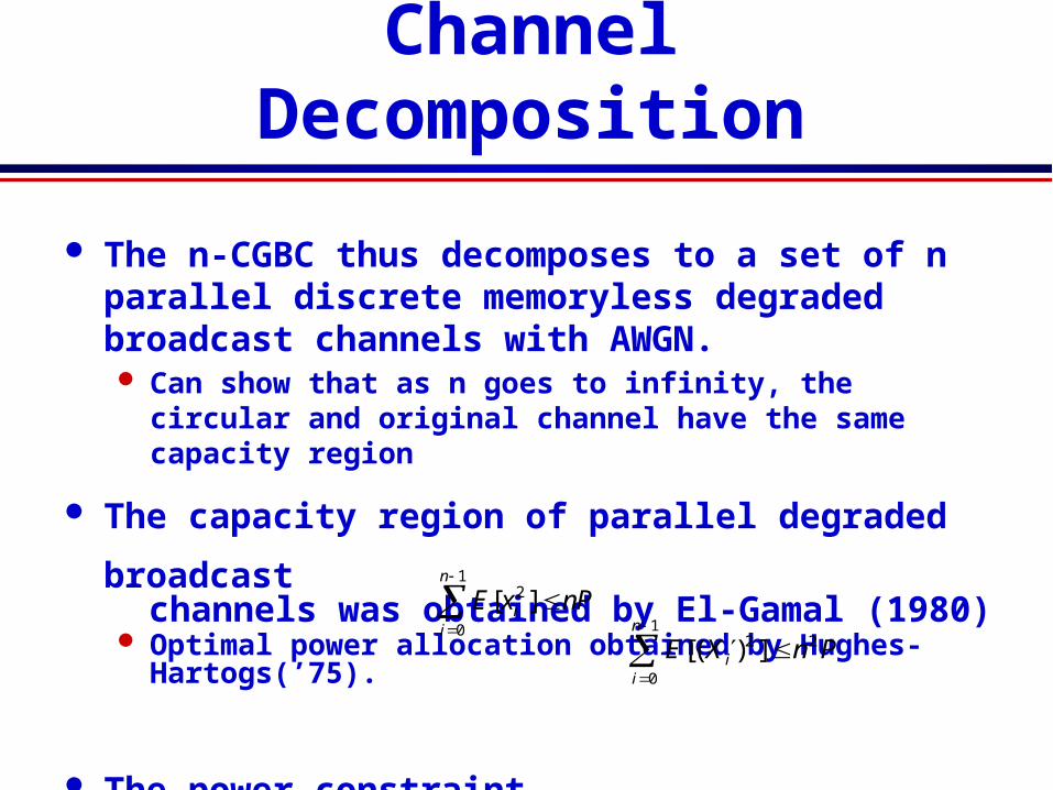
Channel Decomposition
The n-CGBC thus decomposes to a set of n parallel discrete memoryless degraded broadcast channels with AWGN. Can show that as n goes to infinity, the circular and
original channel have the same capacity region
The capacity region of parallel degraded
broadcast channels was obtained by El-Gamal (1980)
Optimal power allocation obtained by Hughes-Hartogs(’75).
The power constraint on the original channel is converted by Parseval’s theorem to on the equivalent channel.
E x nPii
n
[ ]2
0
1
E X n Pii
n
[( ) ]
0
12 2

Capacity Region of Parallel Set
Achievable Rates (no common information)
Capacity Region For 0<b find {aj}, {Pj} to maximize R1+bR2+l SPj. Let (R1
*,R2*)n,b denote the corresponding rate pair.
Cn={(R1*,R2
*)n,b : 0< b }, C=liminfn Cn .1n
PnP
P
P
PR
P
PPR
jj
j j
jj
j jjj
jj
j jjj
jj
j j
jj
jjjj
jjjj
2
: 2: 22
: 1: 11
,10
,)1(
1log5.)1(
1log5.
,)1(
1log5.1log5.
2121
2121
b
R1
R2

Optimal Power Allocation:
Two Level Water Filling

Capacity vs. Frequency

Capacity Region

Multiple Access Channel
Multiple transmitters Transmitter i sends signal Xi with power Pi
Common receiver with AWGN of power
N0B
Received signal:NXY
M
ii
1
X1
X2 X3
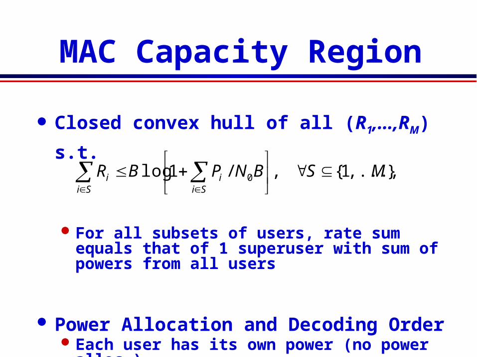
MAC Capacity Region
Closed convex hull of all (R1,…,RM) s.t.
For all subsets of users, rate sum equals that of 1 superuser with sum of powers from all users
Power Allocation and Decoding OrderEach user has its own power (no power
alloc.)Decoding order depends on desired rate
point
},...,1{,/1log 0 MSBNPBRSi
iSi
i

Two-User RegionSuperposition codingw/ interference canc.
SC w/ IC and timesharing or rate splitting
Frequency division
Time division
C1
C2
Ĉ1
Ĉ2
2,1,1log0
i
BN
PBC i
i
,1logˆ,1logˆ10
22
20
11
PBN
PBC
PBN
PBC
SC w/out IC

Fading and ISI
MAC capacity under fading and ISI determined using similar techniques as for the BC
In fading, can define ergodic, outage, and minimum rate capacity similar as in BC caseErgodic capacity obtained based on
AWGN MAC given fixed fading, averaged over fading statistics
Outage can be declared as common, or per user
MAC capacity with ISI obtained by converting to equivalent parallel MAC channels over frequency
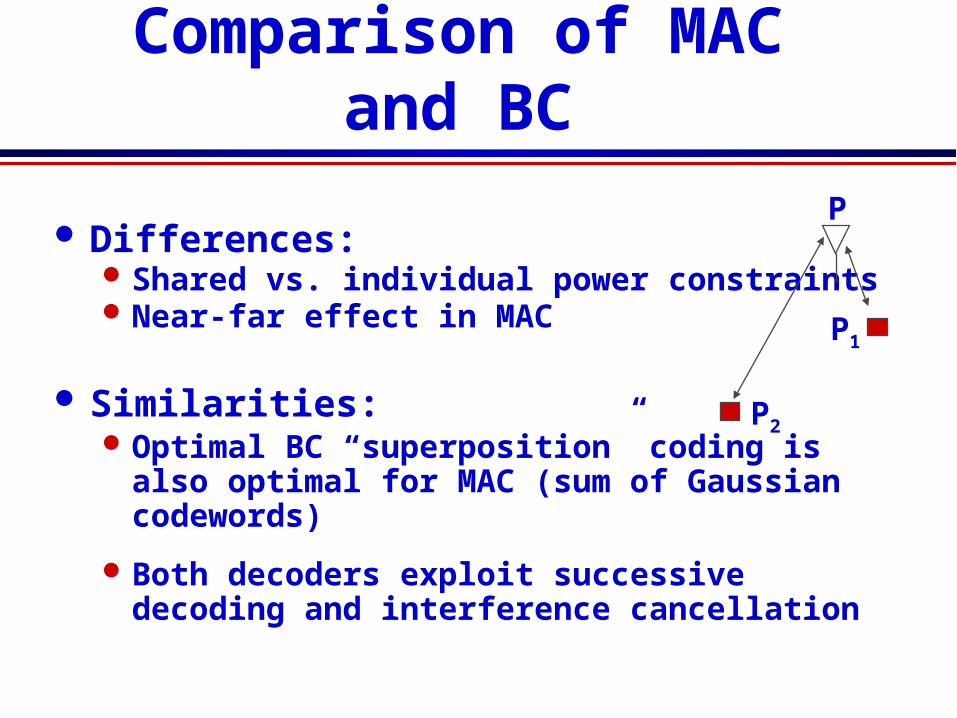
Differences:Shared vs. individual power constraintsNear-far effect in MAC
Similarities:Optimal BC “superposition” coding is also
optimal for MAC (sum of Gaussian codewords)
Both decoders exploit successive decoding and interference cancellation
Comparison of MAC and BC
P
P1
P2

MAC-BC Capacity Regions
MAC capacity region known for many casesConvex optimization problem
BC capacity region typically only known for (parallel) degraded channelsFormulas often not convex
Can we find a connection between the BC and MAC capacity regions?
Duality

Dual Broadcast and MAC Channels
x
)(1 nh
x
)(nhM
+
)(1 nz
)(1 nx
)(nxM
)(1 ny)( 1P
)( MP
x
)(1 nh
x
)(nhM
+
)(nzM
)(nyM
+
)(nz
)(ny)(nx)(P
Gaussian BC and MAC with same channel gains and same noise power at each receiver
Broadcast Channel (BC)Multiple-Access Channel (MAC)

The BC from the MAC
Blue = BCRed = MAC
21 hh
P1=1, P2=1
P1=1.5, P2=0.5
P1=0.5, P2=1.5
),;(),;,( 21212121 hhPPChhPPC BCMAC
MAC with sum-power constraint
PP
MACBC hhPPPChhPC
10
211121 ),;,(),;(

Sum-Power MAC
MAC with sum power constraintPower pooled between MAC
transmittersNo transmitter coordination
P
P
MAC BCSame capacity region!
),;(),;,(),;( 210
211121
1
hhPChhPPPChhPC SumMAC
PPMACBC
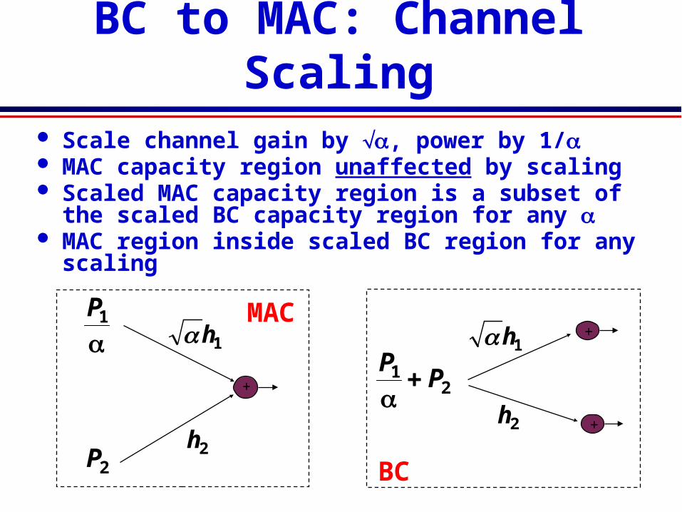
BC to MAC: Channel Scaling
Scale channel gain by a, power by 1/a MAC capacity region unaffected by scaling Scaled MAC capacity region is a subset of the
scaled BC capacity region for any a MAC region inside scaled BC region for any
scaling
1h1P
2P 2h
+
+
21 P
P
1h
2h+
MAC
BC
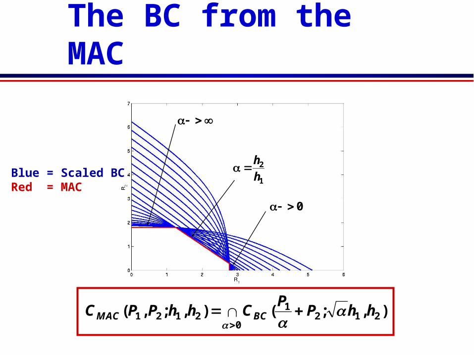
The BC from the MAC
0
2121
2121 ),;(),;,(
hhPP
ChhPPC BCMAC
Blue = Scaled BCRed = MAC
1
2
h
h
0

BC in terms of MAC
MAC in terms of BC
PP
MACBC hhPPPChhPC
10
211121 ),;,(),;(
0
2121
2121 ),;(),;,(
hhPP
ChhPPC BCMAC
Duality: Constant AWGN Channels
What is the relationship betweenthe optimal transmission strategies?

Equate rates, solve for powers
Opposite decoding order Stronger user (User 1) decoded last in BCWeaker user (User 2) decoded last in MAC
Transmission Strategy Transformations
BB
BMM
BB
M
MM
RPh
PhPhR
RPh
Ph
PhR
221
22
222
2
222
2
12
121
222
121
1
)1log()1log(
)1log()1log(

Duality Applies to Different
Fading Channel Capacities
Ergodic (Shannon) capacity: maximum rate averaged over all fading states.
Zero-outage capacity: maximum rate that can be maintained in all fading states.
Outage capacity: maximum rate that can be maintained in all nonoutage fading states.
Minimum rate capacity: Minimum rate maintained in all states, maximize average rate in excess of minimumExplicit transformations between transmission strategies

Duality: Minimum Rate Capacity
BC region known MAC region can only be obtained by duality
Blue = Scaled BCRed = MAC
MAC in terms of BC
What other capacity regions can be obtained by duality?Broadcast MIMO
Channels