ee40 lec 14ee40 lec 14 digital signal and boolean algebradigital signal and boolean...
TRANSCRIPT

EE40 Lec 14EE40 Lec 14
Digital Signal and Boolean AlgebraDigital Signal and Boolean Algebra
Prof Nathan CheungProf. Nathan Cheung
10/14/2009
Reading: Hambley Chapters 7.1-7.4
Slide 1EE40 Fall 2009 Prof. Cheung
Reading: Hambley Chapters 7.1 7.4

Analog Signals
Analog: signal amplitude is continuous with time.
Am plitude M odulated S ignal
1
0.2
0 .4
0 .6
0 .8
mic
rovo
lts
0 8
-0 .6
-0 .4
-0 .2
00 5 10 15 20 25 30 35 40 45 50
Sign
al in
m
-1
-0 .8
T im e in m icroseconds
Slide 2EE40 Fall 2009 Prof. Cheung

Digitalized signal
Digital: signal amplitude is represented by a restricted set of discrete numbers.
Slide 3EE40 Fall 2009 Prof. Cheung

Why Digital?
Di i l i l b i d i d
(For example, why CDROM audio vs. vinyl recordings?)
• Digital signals can be transmitted, received, amplified, and re-transmitted with far less degradationdegradation.
• Digital information is easily and inexpensively stored (in RAM, ROM, etc.), with arbitrary accuracy.
• Complex logical functions are easily expressed as binary functions (e g in control applications)as binary functions (e.g. in control applications).
• Digital signals are easy to manipulate (as we shall see)
Slide 4EE40 Fall 2009 Prof. Cheung
shall see).

Digital Signal Representations
Binary numbers can be used to represent any quantity.y q y
We generally have to agree on some sort of “code”, and the dynamic range of the signal incode , and the dynamic range of the signal in order to know the form and the number of binary digits (“bits”) required.
Example : To encode the signal to an accuracy f 1 t i 64 (1 5% i i ) 6 bi di itof 1 part in 64 (1.5% precision), 6 binary digits
(“bits”) are needed
Slide 5EE40 Fall 2009 Prof. Cheung

Digital Signals• For a digital signal, the voltage must be within
one of two ranges in order to be defined:V
“1” VOH
VDD
1VIH
undefined region increasingvoltage
• Positive Logic: “0”VIL
VOL
voltage
– “low” voltage ≡ logic state 0– “high” voltage ≡ logic state 1
VOL
0 Volts
Slide 6EE40 Fall 2009 Prof. Cheung

Number Base• Number Base B ⇒ B symbols per digit:
–Base 10 (Decimal): 0, 1, 2, 3, 4, 5, 6, 7, 8, 9–Base 2 (Binary): 0, 1
• Number base representation: –d31d30 ... d1d0 is a 32 digit number–value = d31 × B31 + d30 × B30 + ... + d1 × B1 + d0 × B0
E l Bi (B 2) 0 1 (I bi di it• Example : Binary (B=2): 0,1 (In binary digits called “bits”)
11010 = 1 24 + 1 23 + 0 22 + 1 21 + 0 2011010 = 1×24 + 1×23 + 0×22 + 1×21 + 0×20
= 16 + 8 + 2= 26
Slide 7EE40 Fall 2009 Prof. Cheung
Here 5 digit binary number turns into a 2 digit decimal number

Decimal-Binary Conversion
• Decimal Integer to Binary– Repeated Division By 2
Example: Decimal integer 343
Slide 8EE40 Fall 2009 Prof. Cheung

Decimal-Binary Conversion
• Decimal Fraction to Binary Fraction– Repeated Multiplication By 2
Example: Decimal Fraction 0.392
Slide 9EE40 Fall 2009 Prof. Cheung
Other examples: 0.7510=0.112 0.3 ≈.0100112

Binary to Decimal conversion
110001.00122
= 1x25 +1x24 +0x23 +0x22 + 0x21 + 1x20= 1x2 +1x2 +0x2 +0x2 + 0x2 + 1x2+0x2-1+ 0x2-2 + 1x2-3
= 3210 + 1610 + 110 +0.1251010 10 10 10
= 49.12510
Slide 10EE40 Fall 2009 Prof. Cheung
10

Adding Binary Numbers
Addition Rules
Example
Slide 11EE40 Fall 2009 Prof. Cheung

Two’complement of Binary Numbers
Slide 12EE40 Fall 2009 Prof. Cheung

Subtracting Binary Numbers
Find signed two’sFind signed two s complement of substrahend
Subtraction = add the signed binary number toSubtraction add the signed binary number to the signed two’s complement of substrahend
Note: If two numbers to be added have the same sign bit but the result have the
Slide 13EE40 Fall 2009 Prof. Cheung
gopposite sign bit, overflow or underflow has occurred

Hexadecimal Numbers: Base 16
• Hexadecimal: 0 1 2 3 4 5 6 7 8 9 A B C D E F0, 1, 2, 3, 4, 5, 6, 7, 8, 9, A, B, C, D, E, F–Normal digits + 6 more from the alphabet
Conversion: Binary⇔Hex• Conversion: Binary⇔Hex–1 hex digit represents 16 decimal values
4 bi di i 16 d i l l–4 binary digits represent 16 decimal values⇒1 hex digit replaces 4 binary digitsExample:11110110.12=11110110.10002 =F6.816
Slide 14EE40 Fall 2009 Prof. Cheung

Digital Representations of Logical Functions
• Digital signals offer an easy way to perform logical functions, using Boolean algebra.– Variables have two possible values: “true” or “false”
• usually represented by 1 and 0, respectively.
• All modern control systems use this approach.
• Example: Hot tub controller with the following algorithmg g– Turn on the heater if the temperature is less than
desired (T < Tset) and the motor is on and the key it h t ti t th h t t b i l d
Slide 15EE40 Fall 2009 Prof. Cheung
switch to activate the hot tub is closed.

Combinatorial Logic gates
– Combine several logic variable inputs to produce a logic variable output
– Memoryless: output at a given instant depends the input values of that instant.
Slide 16EE40 Fall 2009 Prof. Cheung
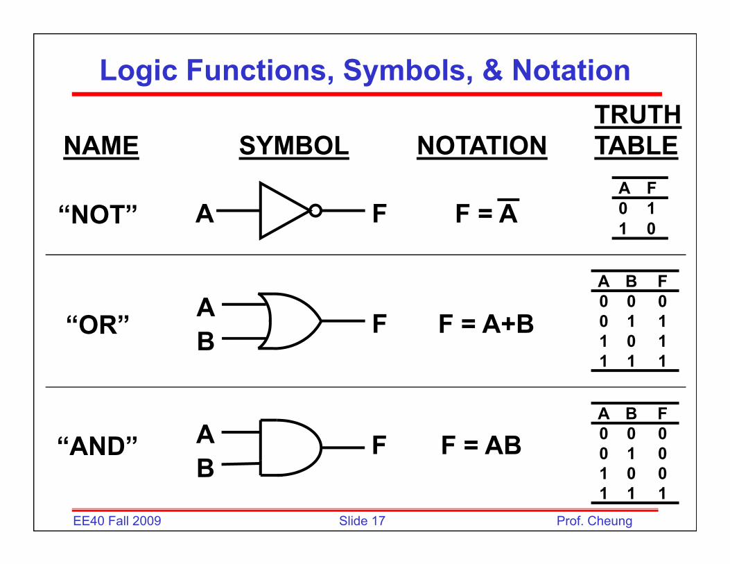
Logic Functions, Symbols, & NotationTRUTH
NAME SYMBOL NOTATION TABLE
“NOT” F = AFAA F0 11 0
“OR” F A+BFAA B F0 0 00 1 1“OR” F = A+BFB0 1 11 0 11 1 1
A B F0 0 00 1 0“AND” F = ABFA
B
Slide 17EE40 Fall 2009 Prof. Cheung
1 0 01 1 1
B

3-Input Gates
Slide 18EE40 Fall 2009 Prof. Cheung

Boolean algebra
Th t f B l l b b• The operators of Boolean algebra may be represented in various ways. Often they are simply written as AND, OR and NOT. p y
• In describing circuits, NAND (NOT AND), NOR (NOT OR) and XOR (eXclusive OR) may also be usedused.
An excellent web site to visithttp://en.wikipedia.org/wiki/Boolean_algebra
• Mathematicians often use + for OR and • for AND (since in some ways those operations are analogous to addition and multiplication in otheranalogous to addition and multiplication in other algebraic structures) and represent NOT by a line drawn above the expression being negated.
Slide 19EE40 Fall 2009 Prof. Cheung
Note: In Hambley text, there is no dot for AND opeartion
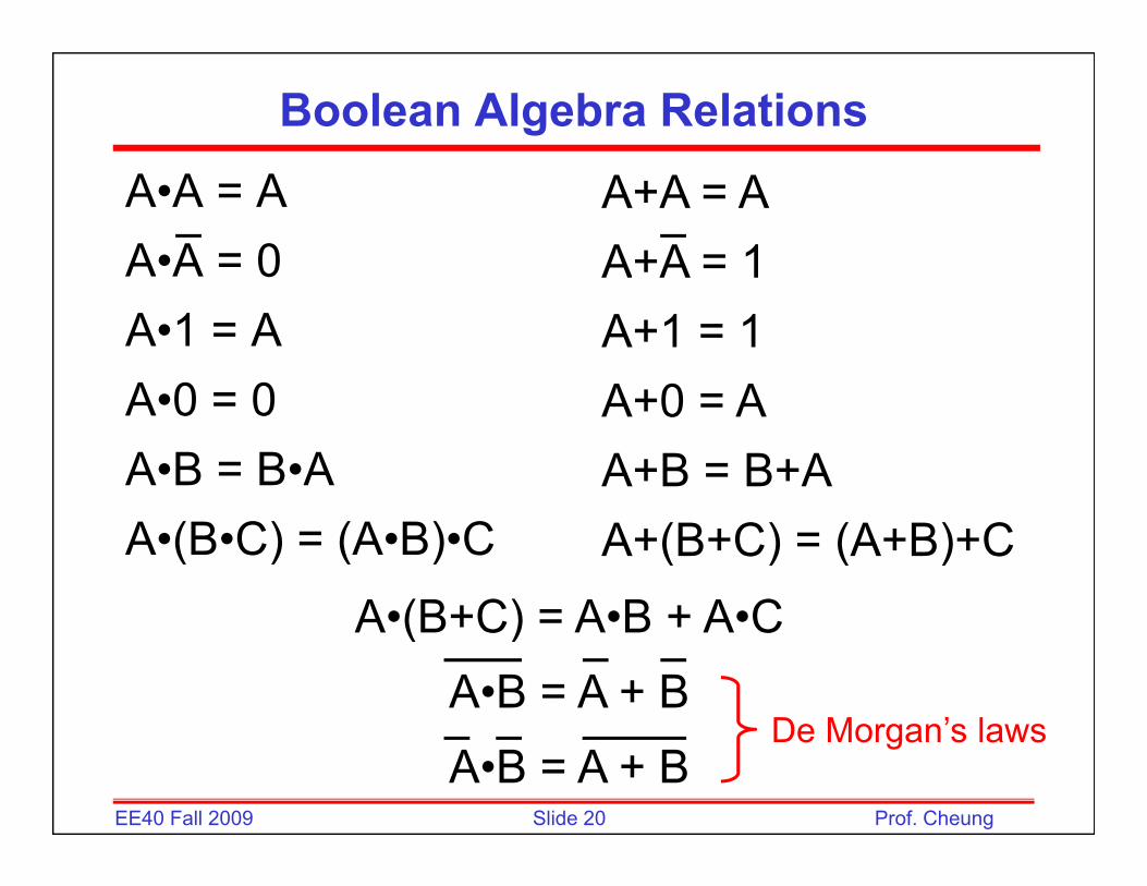
Boolean Algebra Relations
A•A = AA•A = 0
A+A = AA+A = 1A A 0
A•1 = AA 0 0
A A 1A+1 = 1A 0 AA•0 = 0
A•B = B•AA+0 = AA+B = B+A
A•(B•C) = (A•B)•C A+(B+C) = (A+B)+CA•(B+C) = A•B + A•CA•(B+C) = A•B + A•C
A•B = A + BD M ’ l
Slide 20EE40 Fall 2009 Prof. Cheung
A•B = A + BDe Morgan’s laws

Boolean Expression Example
)ED)(DC(ABCCBAF ++++=
AC)BB(AC =+DECEDC
)ED(D)ED(C++=
+++
DE)EDA(CF +++=
Slide 21EE40 Fall 2009 Prof. Cheung

Logic Functions, Symbols, & Notation 2
“NOR” F = A+BFAB
A B F0 0 10 1 01 0 0B 1 0 01 1 0
“NAND” F = ABFAB
A B F0 0 10 1 1
B 1 0 11 1 0
A B F0 0 00 1 11 0 1
“XOR”(exclusive OR)
F = A + BFAB
Slide 22EE40 Fall 2009 Prof. Cheung
1 0 11 1 0
(exclusive OR) B

NAND Gate Implementation
• De Morgan’s law tells us that• De Morgan s law tells us that
is the same asis the same as
• By definition,
is the same as
Slide 23EE40 Fall 2009 Prof. Cheung
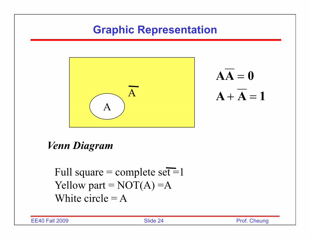
Graphic Representation
0AAA
A1AA
0AA=+
=
A
Venn Diagram
Full square = complete set =1Yellow part = NOT(A) =AWhi i l A
Slide 24EE40 Fall 2009 Prof. Cheung
White circle = A

Graphic Representation of XOR
ABAB
A B+
BAB
BAAB)BA)(BA(BABABA ++=++=+=⊕
Exclusive OR=yellow and blue part – intersection part= exactly when only one of the input is true
Slide 25EE40 Fall 2009 Prof. Cheung
exactly when only one of the input is true

Circuit Realization of XOR Gate
BAAB)BA)(BA(BABABA ++=++=+=⊕
A B⊕
AA
ABB A B⊕
BB
AB
Slide 26EE40 Fall 2009 Prof. Cheung

Logical Sufficiency of NAND Gates• If the inputs to a NAND gate are tied together, an
inverter results
• From De Morgan’s laws, the OR operation can be realized by inverting the input variables and combiningrealized by inverting the input variables and combining the results in a NAND gate.
• Since the basic logic functions (AND OR and NOT) can• Since the basic logic functions (AND, OR, and NOT) can be realized by using only NAND gates, NAND gates are sufficient to realize any combinational logic function.
Slide 27EE40 Fall 2009 Prof. Cheung

Logical Sufficiency of NOR Gates• Show how to realize the AND, OR, and NOT functions
using only NOR gates
Since the basic logic f nctions (AND OR andSince the basic logic functions (AND, OR, and NOT) can be realized by using only NOR gates, NOR gates are sufficient to realize any
Slide 28EE40 Fall 2009 Prof. Cheung
g , g ycombinational logic function.