effect analysis of site class on seismic response of tank-liquid system · 2016-08-23 · effect...
TRANSCRIPT
Effect analysis of site class on seismic response of tank-liquid
system
*Rulin Zhang1) , Xudong Cheng2), Youhai Guan3) and A.A Tarasenko4)
1), 2), 3) College of Pipeline and Civil Engineering, China University of Petroleum,
Qingdao 266580, China 4)
Tyumen State Oil and Gas University, Tyumen 999081, Russian Federation 1)
ABSTRACT Based on the software ANSYS, a tank-liquid coupling finite element model is built, in which the nonlinear lift-off effect between the tank bottom and the foundation is included. Four actual seismic wave recorded in different sites are selected as input to study the effect of site class on the seismic response of tank wall, including the deformation, liquid sloshing and lift-off at bottom. The study results indicate that, large amplitude vertical sloshing with long period occurs on the free surface of liquid under
the seismic input of class-Ⅲ site. Obvious elephant foot deformation occurred near the
bottom of tank wall under the seismic input of class-Ⅰ site and class-Ⅳ site. The local
buckling failure appears at the location close to elephant foot due to the axial compressive stress exceeds the allowable critical stress. Under the seismic input of
class-Ⅳ site, significant nonlinear lift-off and slip deformation occur at tank bottom. The
site class has an important effect on seismic response of storage tank, and should be considered and paid attention in the seismic design of large tanks. It should take appropriate effective measures to reduce the seismic response of the storage tanks if necessary.
Keywords: storage tank;seismic response;tank-liquid coupling;site class; lift-off;
liquid sloshing 1. INTRODUCTION In recent years, the large storage tanks have become important basic facilities for reservoir, reproduction and supply of oil and gas resources. However, once the tanks suffers earthquake damage, it may lead to significant leakage of flammable liquids, fire, explosion, poisoning and other devastating secondary disasters (FANG Hao 2012).
1)
Lecturer
2) Professor
3) Associate Professor
4) Russian Academy of Sciences
Large storage tank is one device with relatively large damage among petrochemical equipment. There are many tanks destroyed during every earthquake in history. Taking into account the economic costs and ease of construction, the real tanks often use non-anchor type that is placed on the free foundation directly. For unanchored tanks, it is hard to offset overturning forces caused by earthquakes only by its own weight, and the outer edge of the base plate will be lifted and separated from the foundation, then lift-off occurs and causes failure of the tank. Therefore the nonlinear lift-off effect of tank bottom plate is one of the main problems in seismic research of unanchored tanks. Currently, seismic response of tanks is mostly using the simplified mass-spring model based on the theory model of Haroun-Housner (Haroun 1983). Goudarzi (Goudarzi 2009) studied the calculation accuracy of mass-spring model in seismic response of tanks. In this paper, a finite element modeling tool is used for investigating the behavior the some selected liquid storage tanks under available earthquake excitations. The study shows the simplified mass spring model doesn’t always provide accurate results for conventionally constructed tanks. In some cases, up to 30%, 35% and 70% average differences between the results of finite element modeling and corresponding mass spring model are calculated for the base shear force, overturning moment and maximum sloshing wave height, respectively. Praveen K. M (Praveen K. M. 2000) provided a simplified seismic design procedure for cylindrical ground-supported tanks, and the procedure considers the impulsive and convective (sloshing) actions of the liquid in flexible steel or concrete tanks fixed to rigid foundations. Livaoglu R (Livaoglu R 2006 ) presented a review of simplified seismic design procedures for elevated tanks and the applicability of general-purpose structural analyses programs to
fluid–structure–soil interaction problems for these kinds of tanks. Ten models are
evaluated by using mechanical and finite-element modelling techniques. An added
mass approach for the fluid–structure interaction, and the massless foundation and
substructure approaches for the soil–structure interactions are presented. However,
these simplified models are difficult to obtain the distribution stress and strain of tank wall, and cannot reflect the buckling failure on the tank wall and other issues. Actually, the seismic problem of large tanks belongs to three-dimensional spatial problem, and the dynamic performance of tanks is very complicated. Especially, the simplified method is difficult to use for the unanchored tanks due to the nonlinear lift-off effect at the tank bottom. Liu Shuai (LIU Shuai 2014) carried on seismic response analysis for pile-soil-LNG tank system using the finite element method. The main dynamic characteristics of unanchored tank are lift-off and multiple nonlinear coupling effects with various factors. Therefore theoretical analysis is difficult for seismic study of large tanks, and often uses the numerical simulation method. Bayraktar (Bayraktar A 2010) studied the issue on the tank's lift-off, which showed the displacement and stress response became more obvious after lift-off. Zhang Xiaochun et al (ZHANG Xiao-chun 2013) studied the horizontal seismic response of unanchored tanks based on the numerical simulation method. Moreover, the impact study of different types of site is not deep enough on the seismic performance for unanchored tanks. Especially the interaction law is still unclear between the site class and the seismic response parameter, which including the effect on the wave height of liquid sloshing, the stress and deformation of tank wall, lift-off at the tank bottom. In this paper, a 3D finite element model of unanchored tank is
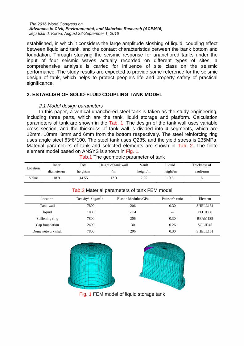
established, in which it considers the large amplitude sloshing of liquid, coupling effect between liquid and tank, and the contact characteristics between the bank bottom and foundation. Through studying the seismic response for unanchored tanks under the input of four seismic waves actually recorded on different types of sites, a comprehensive analysis is carried for influence of site class on the seismic performance. The study results are expected to provide some reference for the seismic design of tank, which helps to protect people's life and property safety of practical significance. 2. ESTABLISH OF SOLID-FLUID COUPLING TANK MODEL 2.1 Model design parameters In this paper, a vertical unanchored steel tank is taken as the study engineering, including three parts, which are the tank, liquid storage and platform. Calculation parameters of tank are shown in the Tab. 1. The design of the tank wall uses variable cross section, and the thickness of tank wall is divided into 4 segments, which are 12mm, 10mm, 8mm and 6mm from the bottom respectively. The steel reinforcing ring uses angle steel 63*8*100. The steel tank uses Q235, and the yield stress is 235MPa. Material parameters of tank and selected elements are shown in Tab. 2. The finite element model based on ANSYS is shown in Fig. 1.
Tab.1 The geometric parameter of tank
Location Inner
diameter/m
Total
height/m
Height of tank wall
/m
Vault
height/m
Liquid
height/m
Thickness of
vault/mm
Value 18.9 14.55 12.3 2.25 10.5 6
Tab.2 Material parameters of tank FEM model
location Density/(kg/m3) Elastic Modulus/GPa Poisson's ratio Element
Tank wall 7800 206 0.30 SHELL181
liquid 1000 2.04 -- FLUID80
Stiffening ring 7800 206 0.30 BEAM188
Cap foundation 2400 30 0.26 SOLID45
Dome network shell 7800 206 0.30 SHELL181
Fig. 1 FEM model of liquid storage tank
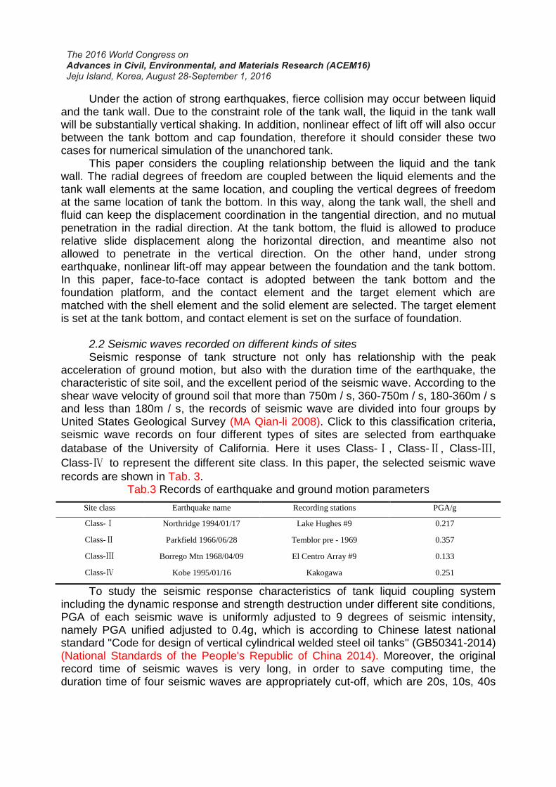
Under the action of strong earthquakes, fierce collision may occur between liquid and the tank wall. Due to the constraint role of the tank wall, the liquid in the tank wall will be substantially vertical shaking. In addition, nonlinear effect of lift off will also occur between the tank bottom and cap foundation, therefore it should consider these two cases for numerical simulation of the unanchored tank. This paper considers the coupling relationship between the liquid and the tank wall. The radial degrees of freedom are coupled between the liquid elements and the tank wall elements at the same location, and coupling the vertical degrees of freedom at the same location of tank the bottom. In this way, along the tank wall, the shell and fluid can keep the displacement coordination in the tangential direction, and no mutual penetration in the radial direction. At the tank bottom, the fluid is allowed to produce relative slide displacement along the horizontal direction, and meantime also not allowed to penetrate in the vertical direction. On the other hand, under strong earthquake, nonlinear lift-off may appear between the foundation and the tank bottom. In this paper, face-to-face contact is adopted between the tank bottom and the foundation platform, and the contact element and the target element which are matched with the shell element and the solid element are selected. The target element is set at the tank bottom, and contact element is set on the surface of foundation. 2.2 Seismic waves recorded on different kinds of sites Seismic response of tank structure not only has relationship with the peak acceleration of ground motion, but also with the duration time of the earthquake, the characteristic of site soil, and the excellent period of the seismic wave. According to the shear wave velocity of ground soil that more than 750m / s, 360-750m / s, 180-360m / s and less than 180m / s, the records of seismic wave are divided into four groups by United States Geological Survey (MA Qian-li 2008). Click to this classification criteria, seismic wave records on four different types of sites are selected from earthquake
database of the University of California. Here it uses Class-Ⅰ, Class-Ⅱ, Class-Ⅲ,
Class-Ⅳ to represent the different site class. In this paper, the selected seismic wave
records are shown in Tab. 3. Tab.3 Records of earthquake and ground motion parameters
Site class Earthquake name Recording stations PGA/g
Class-Ⅰ Northridge 1994/01/17 Lake Hughes #9 0.217
Class-Ⅱ Parkfield 1966/06/28 Temblor pre - 1969 0.357
Class-Ⅲ Borrego Mtn 1968/04/09 El Centro Array #9 0.133
Class-Ⅳ Kobe 1995/01/16 Kakogawa 0.251
To study the seismic response characteristics of tank liquid coupling system including the dynamic response and strength destruction under different site conditions, PGA of each seismic wave is uniformly adjusted to 9 degrees of seismic intensity, namely PGA unified adjusted to 0.4g, which is according to Chinese latest national standard "Code for design of vertical cylindrical welded steel oil tanks" (GB50341-2014) (National Standards of the People's Republic of China 2014). Moreover, the original record time of seismic waves is very long, in order to save computing time, the duration time of four seismic waves are appropriately cut-off, which are 20s, 10s, 40s

and 20s respectively. Here only given acceleration time history curves of seismic waves
under Class-Ⅰand Class-Ⅲ site, and their corresponding Fourier spectrum are also
shown in Fig. 2 and Fig. 3.
(1) Seismic wave acceleration (2) Fourier spectrum of seismic wave
Fig. 2 The acceleration and Fourier spectrum of seismic wave under Class-I site
(1) Seismic wave acceleration (2) Fourier spectrum of seismic wave
Fig. 3 The acceleration and Fourier spectrum of seismic wave under Class-Ⅲ site
It can be seen From Fig. 2 and Fig. 3, the seismic waveform recorded different site conditions and Fourier spectrum are quite different. Seismic wave recorded in Class-I site belongs to the pulse type of seismic wave, and the energy is concentrated
in the high frequency portion (f = 5Hz). However, on the Class-Ⅲ site, the acceleration
attenuation becomes slow after seismic waves peak value. Due to the effect of soft soil, its energy is concentrated in the low frequency portion (f = 0.6Hz), very few high frequency components. 3. MODAL ANALYSIS OF TANK LIQUID COUPLING SYSTEM
0 5 10 15 20-5
-4
-3
-2
-1
0
1
2
3
4
5
Ax/(
m/s
2)
T/s
0 5 10 15 20 250.00
0.03
0.06
0.09
0.12
0.15
Am
pli
tud
e/(m
/s2*
s)
f/Hz
0 10 20 30 40-4
-3
-2
-1
0
1
2
3
4
5
Ax/(
m/s
2)
T/s
0 5 10 15 20 250.00
0.05
0.10
0.15
0.20
0.25
Am
pli
tud
e/(m
/s2*
s)
f/Hz
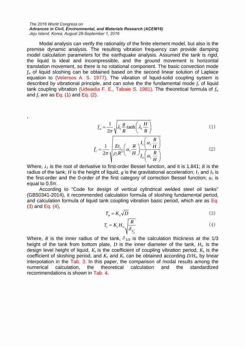
Modal analysis can verify the rationality of the finite element model, but also is the premise dynamic analysis. The resulting vibration frequency can provide damping model calculation parameters for the earthquake analysis. Assumed the tank is rigid, the liquid is ideal and incompressible, and the ground movement is horizontal translation movement, so there is no rotational component. The basic convection mode fw of liquid sloshing can be obtained based on the second linear solution of Laplace equation to (Velersos A. S. 1977). The vibration of liquid-solid coupling system is described by vibrational principle, and can solve the the fundamental mode fc of liquid tank coupling vibration (Udwadia F. E., Tabaie S. 1981). The theoretical formula of fw and fc are as Eq. (1) and Eq. (2).
,
1 1
1tanh
2
w
g Hf
R R (1)
1 1
13
0 1
1
2
sc
l
RI
Et R Hf
RR HI
H
(2)
Where, λ1 is the root of derivative to first-order Bessel function, and it is 1.841; R is the radius of the tank; H is the height of liquid, g is the gravitational acceleration; I1 and I0 is the first-order and the 0-order of the first category of correction Bessel function; α1 is equal to 0.5π. According to "Code for design of vertical cylindrical welded steel oil tanks" (GB50341-2014), it recommended calculation formula of sloshing fundamental period, and calculation formula of liquid tank coupling vibration basic period, which are as Eq. (3) and Eq. (4),
w sT K D
(3)
13
c c w
RT K H
(4)
Where, R is the inner radius of the tank,δ1/3 is the calculation thickness at the 1/3
height of the tank from bottom plate, D is the inner diameter of the tank, Hw is the design level height of liquid, Kc is the coefficient of coupling vibration period, Ks is the coefficient of sloshing period, and Kc and Ks can be obtained according D/Hw by linear interpolation in the Tab. 3. In this paper, the comparison of modal results among the numerical calculation, the theoretical calculation and the standardized recommendations is shown in Tab. 4.
Tab.3 Coefficients of sloshing period and Coefficients of coupling vibration period
D/Hw 0.6 1.0 1.5 2.0 2.5 3.0
Ks 1.047 1.047 1.054 1.074 1.105 1.141
Kc 0.514*10-3 0.44*10-3 0.425*10-3 0.435*10-3 0.461*10-3 0.502*10-3
D/Hw 3.5 4.0 4.5 5.0 5.5 6.0
Ks 1.184 1.230 1.277 1.324 1.371 1.418
Kc 0.537*10-3 0.58*10-3 0.62*10-3 0.681*10-3 0.736*10-3 0.791*10-3
Tab.4 Comparison of natural frequency results of liquid storage tank
Natural
frequency Numerical results/ Hz
Theoretical calculation results Standardized recommendations
Results/ Hz Error/% Results/ Hz Error/%
fw 0.228 0.216 5.56 0.216 5.56
fc 7.046 7.084 0.54 7.188 1.98
As can be seen from the Tab. 4, for the liquid tank system established in this paper, the calculating natural sloshing frequency of liquid and fundamental coupling vibration frequency are 0.228Hz and 7.046Hz respectively, and are all very close to theoretical values and standardized recommendations values, the maximum error is only 5.56 %, which is within the permissible error range of the project. Therefore the reasonableness is verified for using the simulation method of tank liquid system. 4. RESULTS ANALYSIS AND DISCUSSION To study the characteristics and destruction rules under the four kinds of site conditions, in the following results Figures, the symbol C1, C2, C3, C4 represent the simulation results of tank under the input of seismic waves recorded on the site of
Class-Ⅰ, Class-Ⅱ, Class-Ⅲ, and Class-Ⅳ respectively.
4.1 Horizontal displacement of tank wall Slip may occur between the tank bottom and foundation under earthquake. In the paper, the relative displacement of the tank is obtained by the displacement on the location of tank wall minus the corresponding displacement at the bottom, and the following displacement in this paper refers to the relative displacement. Select each point on the left and right sides position cross-section along the wave tank, and analyze the relative horizontal displacement. The selected locations are shown in Fig. 4.
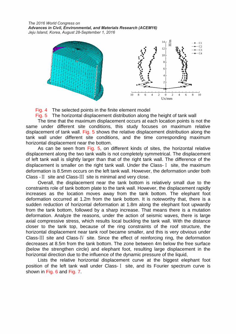
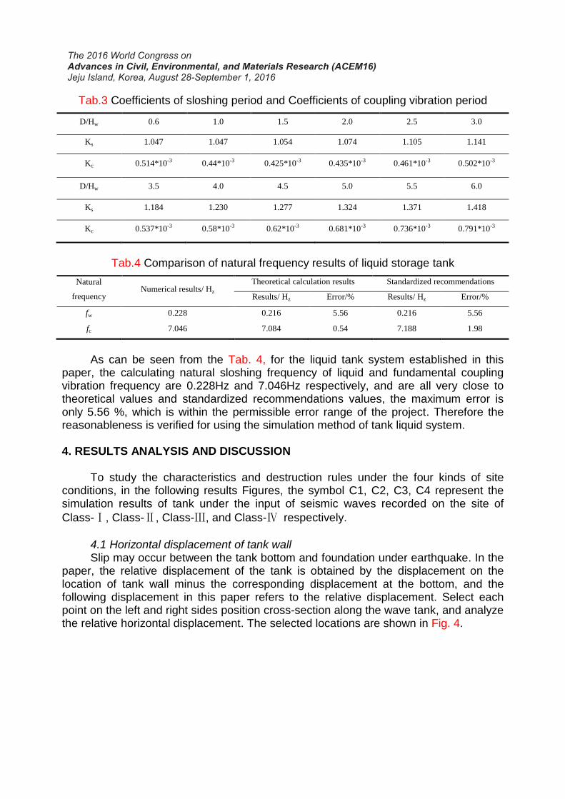
Fig. 4 The selected points in the finite element model Fig. 5 The horizontal displacement distribution along the height of tank wall
The time that the maximum displacement occurs at each location points is not the same under different site conditions, this study focuses on maximum relative displacement of tank wall. Fig. 5 shows the relative displacement distribution along the tank wall under different site conditions, and the time corresponding maximum horizontal displacement near the bottom. As can be seen from Fig. 5, on different kinds of sites, the horizontal relative displacement along the two tank walls is not completely symmetrical. The displacement of left tank wall is slightly larger than that of the right tank wall. The difference of the
displacement is smaller on the right tank wall. Under the Class-Ⅰ site, the maximum
deformation is 8.5mm occurs on the left tank wall. However, the deformation under both
Class -Ⅱ site and Class-Ⅲ site is minimal and very close.
Overall, the displacement near the tank bottom is relatively small due to the constraints role of tank bottom plate to the tank wall. However, the displacement rapidly increases as the location moves away from the tank bottom. The elephant foot deformation occurred at 1.2m from the tank bottom. It is noteworthy that, there is a sudden reduction of horizontal deformation at 1.8m along the elephant foot upwardly from the tank bottom, followed by a sharp increase. That means there is a mutation deformation. Analyze the reasons, under the action of seismic waves, there is large axial compressive stress, which results local buckling the tank wall. With the distance closer to the tank top, because of the ring constraints of the roof structure, the horizontal displacement near tank roof became smaller, and this is very obvious under
Class-Ⅲ site and Class-Ⅳ site. Since the effect of reinforcing ring, the deformation
decreases at 8.5m from the tank bottom. The zone between 4m below the free surface (below the strengthen circle) and elephant foot, resulting large displacement in the horizontal direction due to the influence of the dynamic pressure of the liquid, Lists the relative horizontal displacement curve at the biggest elephant foot
position of the left tank wall under Class-Ⅰ site, and its Fourier spectrum curve is
shown in Fig. 6 and Fig. 7.
10 8 6 4 2 0 2 4 6 8 10
0
2
4
6
8
10
12
14 C1
C2
C3
C4
Ux/mm
H/m
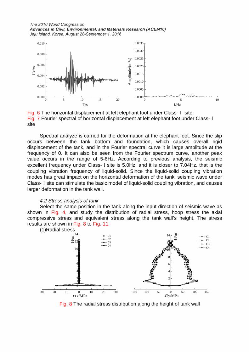
Fig. 6 The horizontal displacement at left elephant foot under Class-Ⅰ site Fig. 7 Fourier spectral of horizontal displacement at left elephant foot under Class-Ⅰ site Spectral analyze is carried for the deformation at the elephant foot. Since the slip occurs between the tank bottom and foundation, which causes overall rigid displacement of the tank, and in the Fourier spectral curve it is large amplitude at the frequency of 0. It can also be seen from the Fourier spectrum curve, another peak value occurs in the range of 5-6Hz. According to previous analysis, the seismic
excellent frequency under Class-Ⅰsite is 5.0Hz, and it is closer to 7.04Hz, that is the
coupling vibration frequency of liquid-solid. Since the liquid-solid coupling vibration modes has great impact on the horizontal deformation of the tank, seismic wave under
Class-Ⅰsite can stimulate the basic model of liquid-solid coupling vibration, and causes
larger deformation in the tank wall. 4.2 Stress analysis of tank Select the same position in the tank along the input direction of seismic wave as shown in Fig. 4, and study the distribution of radial stress, hoop stress the axial compressive stress and equivalent stress along the tank wall’s height. The stress results are shown in Fig. 8 to Fig. 11. (1)Radial stress
Fig. 8 The radial stress distribution along the height of tank wall
0 5 10 15 200.000
0.002
0.004
0.006
0.008
0.010
Ux/m
T/s
0 5 100.0000
0.0005
0.0010
0.0015
0.0020
0.0025
0.0030
0.0035
Am
pli
tude/
(m*s)
f/Hz
30 20 10 0 10 20 30
0
2
4
6
8
10
12
14 C1
C2
C3
C4
x/MPa
H/m
150 100 50 0 50 100 150
0
2
4
6
8
10
12
14
y/MPa
C1
C2
C3
C4
H/m
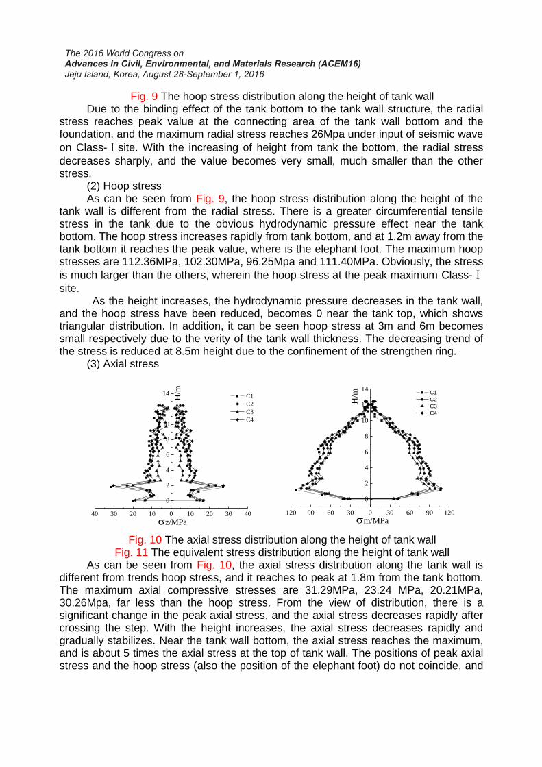
Fig. 9 The hoop stress distribution along the height of tank wall Due to the binding effect of the tank bottom to the tank wall structure, the radial stress reaches peak value at the connecting area of the tank wall bottom and the foundation, and the maximum radial stress reaches 26Mpa under input of seismic wave
on Class-Ⅰsite. With the increasing of height from tank the bottom, the radial stress
decreases sharply, and the value becomes very small, much smaller than the other stress. (2) Hoop stress As can be seen from Fig. 9, the hoop stress distribution along the height of the tank wall is different from the radial stress. There is a greater circumferential tensile stress in the tank due to the obvious hydrodynamic pressure effect near the tank bottom. The hoop stress increases rapidly from tank bottom, and at 1.2m away from the tank bottom it reaches the peak value, where is the elephant foot. The maximum hoop stresses are 112.36MPa, 102.30MPa, 96.25Mpa and 111.40MPa. Obviously, the stress
is much larger than the others, wherein the hoop stress at the peak maximum Class-Ⅰ
site. As the height increases, the hydrodynamic pressure decreases in the tank wall, and the hoop stress have been reduced, becomes 0 near the tank top, which shows triangular distribution. In addition, it can be seen hoop stress at 3m and 6m becomes small respectively due to the verity of the tank wall thickness. The decreasing trend of the stress is reduced at 8.5m height due to the confinement of the strengthen ring. (3) Axial stress
Fig. 10 The axial stress distribution along the height of tank wall Fig. 11 The equivalent stress distribution along the height of tank wall
As can be seen from Fig. 10, the axial stress distribution along the tank wall is different from trends hoop stress, and it reaches to peak at 1.8m from the tank bottom. The maximum axial compressive stresses are 31.29MPa, 23.24 MPa, 20.21MPa, 30.26Mpa, far less than the hoop stress. From the view of distribution, there is a significant change in the peak axial stress, and the axial stress decreases rapidly after crossing the step. With the height increases, the axial stress decreases rapidly and gradually stabilizes. Near the tank wall bottom, the axial stress reaches the maximum, and is about 5 times the axial stress at the top of tank wall. The positions of peak axial stress and the hoop stress (also the position of the elephant foot) do not coincide, and
40 30 20 10 0 10 20 30 40
0
2
4
6
8
10
12
14
z/MPa
C1
C2
C3
C4
H/m
120 90 60 30 0 30 60 90 120
0
2
4
6
8
10
12
14
m/MPa
C1
C2
C3
C4
H/m
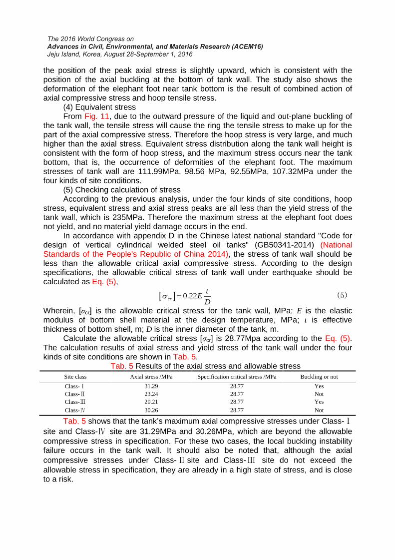
the position of the peak axial stress is slightly upward, which is consistent with the position of the axial buckling at the bottom of tank wall. The study also shows the deformation of the elephant foot near tank bottom is the result of combined action of axial compressive stress and hoop tensile stress. (4) Equivalent stress From Fig. 11, due to the outward pressure of the liquid and out-plane buckling of the tank wall, the tensile stress will cause the ring the tensile stress to make up for the part of the axial compressive stress. Therefore the hoop stress is very large, and much higher than the axial stress. Equivalent stress distribution along the tank wall height is consistent with the form of hoop stress, and the maximum stress occurs near the tank bottom, that is, the occurrence of deformities of the elephant foot. The maximum stresses of tank wall are 111.99MPa, 98.56 MPa, 92.55MPa, 107.32MPa under the four kinds of site conditions. (5) Checking calculation of stress According to the previous analysis, under the four kinds of site conditions, hoop stress, equivalent stress and axial stress peaks are all less than the yield stress of the tank wall, which is 235MPa. Therefore the maximum stress at the elephant foot does not yield, and no material yield damage occurs in the end. In accordance with appendix D in the Chinese latest national standard "Code for design of vertical cylindrical welded steel oil tanks" (GB50341-2014) (National Standards of the People's Republic of China 2014), the stress of tank wall should be less than the allowable critical axial compressive stress. According to the design specifications, the allowable critical stress of tank wall under earthquake should be calculated as Eq. (5),
0.22 cr
tE
D (5)
Wherein, [σcr] is the allowable critical stress for the tank wall, MPa; E is the elastic modulus of bottom shell material at the design temperature, MPa; t is effective thickness of bottom shell, m; D is the inner diameter of the tank, m. Calculate the allowable critical stress [σcr] is 28.77Mpa according to the Eq. (5). The calculation results of axial stress and yield stress of the tank wall under the four kinds of site conditions are shown in Tab. 5.
Tab. 5 Results of the axial stress and allowable stress
Site class Axial stress /MPa Specification critical stress /MPa Buckling or not
Class-Ⅰ 31.29 28.77 Yes
Class-Ⅱ 23.24 28.77 Not
Class-Ⅲ 20.21 28.77 Yes
Class-Ⅳ 30.26 28.77 Not
Tab. 5 shows that the tank’s maximum axial compressive stresses under Class-Ⅰ
site and Class-Ⅳ site are 31.29MPa and 30.26MPa, which are beyond the allowable
compressive stress in specification. For these two cases, the local buckling instability failure occurs in the tank wall. It should also be noted that, although the axial
compressive stresses under Class-Ⅱ site and Class-Ⅲ site do not exceed the
allowable stress in specification, they are already in a high state of stress, and is close to a risk.

4.3 Lift-off and slip of floor and result analysis Under the strong action of ground motion, when the overturning moment exceeds the resistance moment of tank, the edge of the tank floor will be open to off with foundation, which lift-off happened in the tank. For the non-anchor tank, the lift-off will change the original stress field distribution, and thereby the possibility of failure may increase, then causing leakage of fluid. Due to the seismic wave excitation and hydrodynamic pressure effect, some lateral slippage happens between the bottom of the tank and the cap foundation. Slip sliding performance between the tank floor and foundation, the earthquake in this slide will reduce the seismic response of the plate. Select the left and right end positions at the tank bottom to analyze its lift-off deformation. The results show that, under four kinds of site conditions, the maximum lift-off all happen on the right bottom of the tank. Fig. 12 shows the time history liftoff curve at right endpoint of tank bottom. Fig. 13 shows the history curves under different site conditions can bottom right-hand endpoint slip.
Fig. 12 The lift-off response at right end of tank bottom Fig. 13 The slip response at right end of tank bottom
The tank deformation and lift-off at tank bottom under Class-Ⅰ site at 6.84s is
given in Fig. 14 and Fig. 15 . The slip at tank bottom under Class-Ⅳsite at the end time
of seismic wave input is shown in Fig. 16.
Fig. 14 Deformation of tank under Class-Ⅰ site(t=6.84s)
0 5 10 15 20 25 30 35 400.000
0.002
0.004
0.006
0.008
Uz/
m
T/s
C1
C2
C3
C4
0 5 10 15 20 25 30 35 400.000
0.005
0.010
0.015
0.020
0.025
Ux/m
T/s
C1
C2
C3
C4
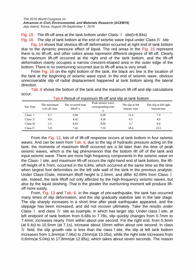
Fig. 15 The lift-off area at the tank bottom under Class-Ⅰ site(t=6.84s)
Fig. 16 The slip of tank bottom at the end of seismic wave input under Class-Ⅳ site
Fig. 14 shows that obvious lift-off deformation occurred at right end of tank bottom due to the dynamic pressure effect of liquid. The red areas in the Fig. 15 represent there is no lift-off, and other colors areas represent different degrees of lift-off. Clearly the maximum lift-off occurred at the right end of the tank bottom, and the lift-off deformation mainly occupies a narrow crescent-shaped area in the outer edge of the bottom. There is no overturning occurred due to lift-off area is very small. From Fig. 16 on the right bottom of the tank, the black arc line is the location of the tank at the beginning of seismic wave input. In the end of seismic wave, obvious unrecoverable slip of radial displacement happened at tank bottom along the lateral direction. Tab. 6 shows the bottom of the tank and the maximum lift-off and slip calculations occur.
Tab.6 Result of maximum lift-off and slip at tank bottom
Site Type The maximum
Lift-off /mm
The occurred time
liftoff /s
Peak seismic wave
corresponding time
/s
The slip at left
bottom /mm
The slip at left right
bottom/mm
Class-Ⅰ 6.7 6.84 6.68 11.4 7.9
Class-Ⅱ 4.0 4.42 4.36 6.1 4.0
Class-Ⅲ 2.5 8.65 8.60 3.7 0.6
Class-Ⅳ 5.8 7.42 7.33 18.4 23.5
From the Fig. 12, lots of of lift-off response occurs at tank bottom in four seismic waves. And can be seen from Tab. 6, due to the lag of hydraulic pressure acting on the tank, the moments of maximum liftoff occurred are a bit later than the time of peak seismic waves, which is the lag phenomenon that the bottom lift off of the tank and input seismic wave. There are more high frequency components in the seismic wave on
the Class-Ⅰsite, and maximum lift-off occurs the right-hand end of tank bottom, the lift-
off height of 6.7mm, occurred in the 6.84s, which occurred at the same time as the time when largest foot deformities on the left side wall of the tank in the previous analysis.
Under Class-Ⅲsite, minimum liftoff height is 2.5mm, and differ 62.69% from Class-Ⅰ
site. Indeed, the tank liftoff not only affected by the high-frequency seismic waves, but also by the liquid sloshing, That is the greater the overturning moment will produce lift-off more easily. From, Fig. 13 and Tab. 6, in the stage of pre-earthquake, the tank has occurred many times of slip deformation, and the slip gradually stabilize late in the late stage. The slip sharply increases in a short time after peak earthquake appeared, and the slippage has been increased, and did not recover ultimately. Take the results under
Class-Ⅰ and class Ⅳ site as example, in which has larger slip. Under classⅠsite, at
left endpoint of tank bottom from 6.68s to 7.78s, slip quickly changes from 0.7mm to 7.4mm, increases nearly 7mm within about one second. For the right end, from 0.3mm (at 6.4s) to 10.5mm (at 7.1s), increase about 10mm within about one second. In class
Ⅳ field, the slip growth rate is less than the classⅠsite, the slip at left tank bottom
increases from 1.3mm(at 7.06s) to 23mm(at 13.05s), while the right side increases from 0.6mm(at 5.04s) to 17.8mm(at 12.85s), which takes about seven seconds. The reason
is under class Ⅳ field, the duration time of larger seismic wave energy is longer, so
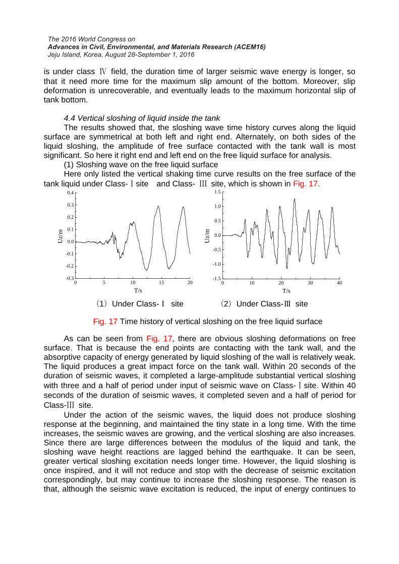
that it need more time for the maximum slip amount of the bottom. Moreover, slip deformation is unrecoverable, and eventually leads to the maximum horizontal slip of tank bottom. 4.4 Vertical sloshing of liquid inside the tank The results showed that, the sloshing wave time history curves along the liquid surface are symmetrical at both left and right end. Alternately, on both sides of the liquid sloshing, the amplitude of free surface contacted with the tank wall is most significant. So here it right end and left end on the free liquid surface for analysis. (1) Sloshing wave on the free liquid surface Here only listed the vertical shaking time curve results on the free surface of the
tank liquid under Class-Ⅰsite and Class- Ⅲ site, which is shown in Fig. 17.
(1)Under Class-Ⅰ site (2)Under Class-Ⅲ site
Fig. 17 Time history of vertical sloshing on the free liquid surface
As can be seen from Fig. 17, there are obvious sloshing deformations on free surface. That is because the end points are contacting with the tank wall, and the absorptive capacity of energy generated by liquid sloshing of the wall is relatively weak. The liquid produces a great impact force on the tank wall. Within 20 seconds of the duration of seismic waves, it completed a large-amplitude substantial vertical sloshing
with three and a half of period under input of seismic wave on Class-Ⅰsite. Within 40
seconds of the duration of seismic waves, it completed seven and a half of period for
Class-Ⅲ site.
Under the action of the seismic waves, the liquid does not produce sloshing response at the beginning, and maintained the tiny state in a long time. With the time increases, the seismic waves are growing, and the vertical sloshing are also increases. Since there are large differences between the modulus of the liquid and tank, the sloshing wave height reactions are lagged behind the earthquake. It can be seen, greater vertical sloshing excitation needs longer time. However, the liquid sloshing is once inspired, and it will not reduce and stop with the decrease of seismic excitation correspondingly, but may continue to increase the sloshing response. The reason is that, although the seismic wave excitation is reduced, the input of energy continues to
0 5 10 15 20-0.3
-0.2
-0.1
0.0
0.1
0.2
0.3
0.4
Uz/
m
T/s
0 10 20 30 40-1.5
-1.0
-0.5
0.0
0.5
1.0
1.5
Uz/
m
T/s
increase, and the sloshing amplitude continues to increase. Due to the lag effect of the liquid, when seismic wave input stops, the shaking did not stop immediately, but free vibration occurs continually. When input of seismic waves stop, the fluctuation will
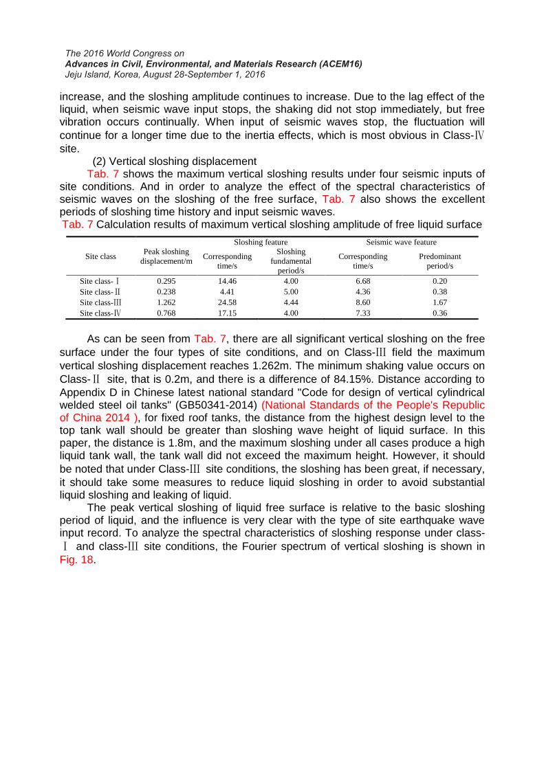
continue for a longer time due to the inertia effects, which is most obvious in Class-Ⅳsite. (2) Vertical sloshing displacement Tab. 7 shows the maximum vertical sloshing results under four seismic inputs of site conditions. And in order to analyze the effect of the spectral characteristics of seismic waves on the sloshing of the free surface, Tab. 7 also shows the excellent periods of sloshing time history and input seismic waves. Tab. 7 Calculation results of maximum vertical sloshing amplitude of free liquid surface
Site class Peak sloshing
displacement/m
Sloshing feature Seismic wave feature
Corresponding
time/s
Sloshing
fundamental
period/s
Corresponding
time/s
Predominant
period/s
Site class-Ⅰ 0.295 14.46 4.00 6.68 0.20
Site class-Ⅱ 0.238 4.41 5.00 4.36 0.38
Site class-Ⅲ 1.262 24.58 4.44 8.60 1.67
Site class-Ⅳ 0.768 17.15 4.00 7.33 0.36
As can be seen from Tab. 7, there are all significant vertical sloshing on the free
surface under the four types of site conditions, and on Class-Ⅲ field the maximum
vertical sloshing displacement reaches 1.262m. The minimum shaking value occurs on
Class-Ⅱ site, that is 0.2m, and there is a difference of 84.15%. Distance according to
Appendix D in Chinese latest national standard "Code for design of vertical cylindrical welded steel oil tanks" (GB50341-2014) (National Standards of the People's Republic of China 2014 ), for fixed roof tanks, the distance from the highest design level to the top tank wall should be greater than sloshing wave height of liquid surface. In this paper, the distance is 1.8m, and the maximum sloshing under all cases produce a high liquid tank wall, the tank wall did not exceed the maximum height. However, it should
be noted that under Class-Ⅲ site conditions, the sloshing has been great, if necessary,
it should take some measures to reduce liquid sloshing in order to avoid substantial liquid sloshing and leaking of liquid. The peak vertical sloshing of liquid free surface is relative to the basic sloshing period of liquid, and the influence is very clear with the type of site earthquake wave input record. To analyze the spectral characteristics of sloshing response under class-
Ⅰ and class-Ⅲ site conditions, the Fourier spectrum of vertical sloshing is shown in
Fig. 18.
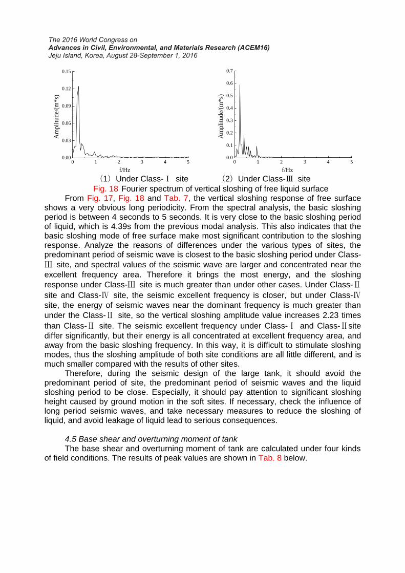
(1)Under Class-Ⅰ site (2)Under Class-Ⅲ site
Fig. 18 Fourier spectrum of vertical sloshing of free liquid surface From Fig. 17, Fig. 18 and Tab. 7, the vertical sloshing response of free surface shows a very obvious long periodicity. From the spectral analysis, the basic sloshing period is between 4 seconds to 5 seconds. It is very close to the basic sloshing period of liquid, which is 4.39s from the previous modal analysis. This also indicates that the basic sloshing mode of free surface make most significant contribution to the sloshing response. Analyze the reasons of differences under the various types of sites, the predominant period of seismic wave is closest to the basic sloshing period under Class-
Ⅲ site, and spectral values of the seismic wave are larger and concentrated near the
excellent frequency area. Therefore it brings the most energy, and the sloshing
response under Class-Ⅲ site is much greater than under other cases. Under Class-Ⅱ
site and Class-Ⅳ site, the seismic excellent frequency is closer, but under Class-Ⅳ
site, the energy of seismic waves near the dominant frequency is much greater than
under the Class-Ⅱ site, so the vertical sloshing amplitude value increases 2.23 times
than Class-Ⅱ site. The seismic excellent frequency under Class-Ⅰ and Class-Ⅱsite
differ significantly, but their energy is all concentrated at excellent frequency area, and away from the basic sloshing frequency. In this way, it is difficult to stimulate sloshing modes, thus the sloshing amplitude of both site conditions are all little different, and is much smaller compared with the results of other sites. Therefore, during the seismic design of the large tank, it should avoid the predominant period of site, the predominant period of seismic waves and the liquid sloshing period to be close. Especially, it should pay attention to significant sloshing height caused by ground motion in the soft sites. If necessary, check the influence of long period seismic waves, and take necessary measures to reduce the sloshing of liquid, and avoid leakage of liquid lead to serious consequences. 4.5 Base shear and overturning moment of tank The base shear and overturning moment of tank are calculated under four kinds of field conditions. The results of peak values are shown in Tab. 8 below.
0 1 2 3 4 50.00
0.03
0.06
0.09
0.12
0.15
Am
pli
tud
e/(m
*s)
f/Hz
0 1 2 3 4 50.0
0.1
0.2
0.3
0.4
0.5
0.6
0.7
Am
pli
tude/
(m*s)
f/Hz
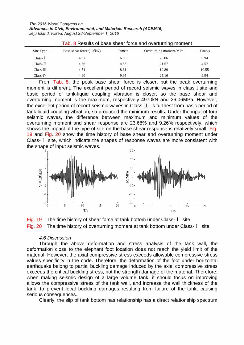
Tab. 8 Results of base shear force and overturning moment
Site Type Base shear force/(103kN) Time/s Overturning moment/MPa Time/s
Class-Ⅰ 4.97 6.96 26.06 6.94
Class-Ⅱ 4.66 4.53 21.57 4.57
Class-Ⅲ 4.51 8.61 19.89 10.55
Class-Ⅳ 4.90 9.95 25.16 9.94
From Tab. 8, the peak base shear force is closer, but the peak overturning
moment is different. The excellent period of record seismic waves in classⅠsite and
basic period of tank-liquid coupling vibration is closer, so the base shear and overturning moment is the maximum, respectively 4970kN and 26.06MPa. However,
the excellent period of record seismic waves in Class-Ⅲ is furthest from basic period of
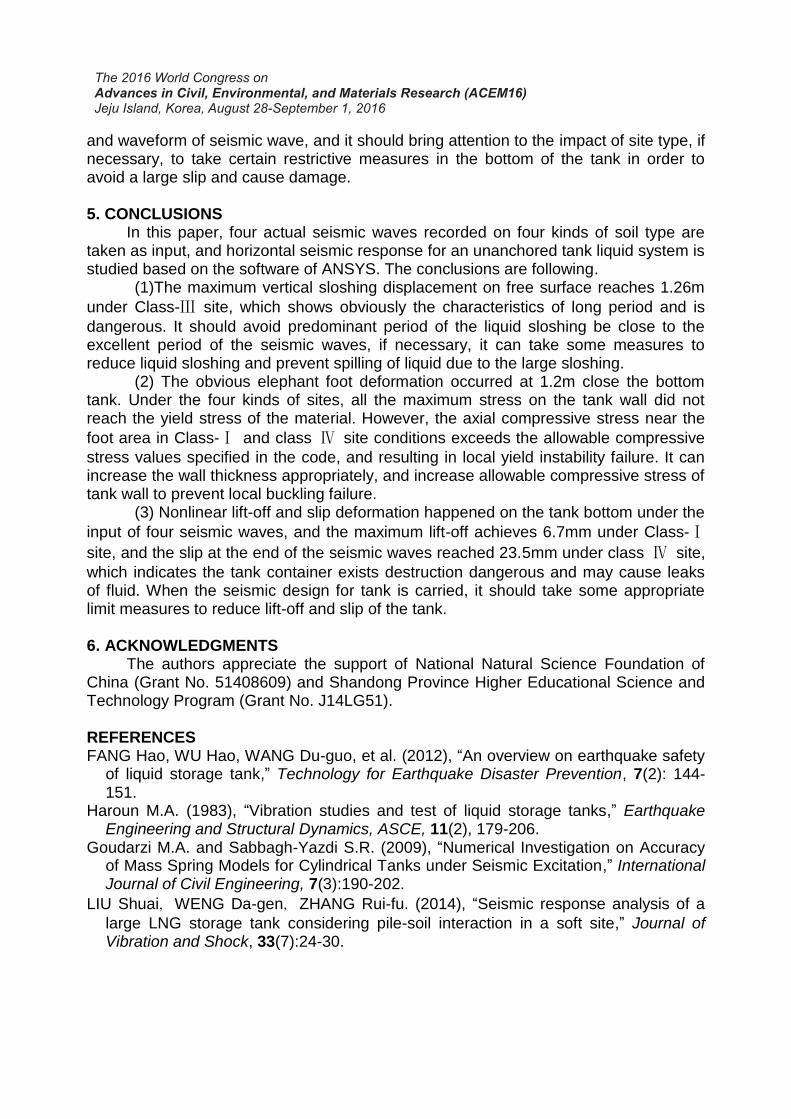
tank liquid coupling vibration, so produced the minimum results. Under the input of four seismic waves, the difference between maximum and minimum values of the overturning moment and shear response are 23.68% and 9.26% respectively, which shows the impact of the type of site on the base shear response is relatively small. Fig. 19 and Fig. 20 show the time history of base shear and overturning moment under
Class-Ⅰ site, which indicate the shapes of response waves are more consistent with
the shape of input seismic waves.
Fig. 19 The time history of shear force at tank bottom under Class-Ⅰ site
Fig. 20 The time history of overturning moment at tank bottom under Class-Ⅰ site
4.6 Discussion Through the above deformation and stress analysis of the tank wall, the deformation close to the elephant foot location does not reach the yield limit of the material. However, the axial compressive stress exceeds allowable compressive stress values specificity in the code. Therefore, the deformation of the foot under horizontal earthquake belong to partial buckling damage induced by the axial compressive stress exceeds the critical buckling stress, not the strength damage of the material. Therefore, when making seismic design of a large volume tank, it should focus on improving allows the compressive stress of the tank wall, and increase the wall thickness of the tank, to prevent local buckling damages resulting from failure of the tank, causing serious consequences. Clearly, the slip of tank bottom has relationship has a direct relationship spectrum
0 5 10 15 20-6
-4
-2
0
2
4
6
V×
10
3/k
N
T/s
0 5 10 15 20-30
-20
-10
0
10
20
30
M/M
Pa
T/s
and waveform of seismic wave, and it should bring attention to the impact of site type, if necessary, to take certain restrictive measures in the bottom of the tank in order to avoid a large slip and cause damage.
5. CONCLUSIONS In this paper, four actual seismic waves recorded on four kinds of soil type are taken as input, and horizontal seismic response for an unanchored tank liquid system is studied based on the software of ANSYS. The conclusions are following. (1)The maximum vertical sloshing displacement on free surface reaches 1.26m
under Class-Ⅲ site, which shows obviously the characteristics of long period and is
dangerous. It should avoid predominant period of the liquid sloshing be close to the excellent period of the seismic waves, if necessary, it can take some measures to reduce liquid sloshing and prevent spilling of liquid due to the large sloshing. (2) The obvious elephant foot deformation occurred at 1.2m close the bottom tank. Under the four kinds of sites, all the maximum stress on the tank wall did not reach the yield stress of the material. However, the axial compressive stress near the
foot area in Class-Ⅰ and class Ⅳ site conditions exceeds the allowable compressive
stress values specified in the code, and resulting in local yield instability failure. It can increase the wall thickness appropriately, and increase allowable compressive stress of tank wall to prevent local buckling failure. (3) Nonlinear lift-off and slip deformation happened on the tank bottom under the
input of four seismic waves, and the maximum lift-off achieves 6.7mm under Class-Ⅰ
site, and the slip at the end of the seismic waves reached 23.5mm under class Ⅳ site,
which indicates the tank container exists destruction dangerous and may cause leaks of fluid. When the seismic design for tank is carried, it should take some appropriate limit measures to reduce lift-off and slip of the tank. 6. ACKNOWLEDGMENTS The authors appreciate the support of National Natural Science Foundation of China (Grant No. 51408609) and Shandong Province Higher Educational Science and Technology Program (Grant No. J14LG51). REFERENCES FANG Hao, WU Hao, WANG Du-guo, et al. (2012), “An overview on earthquake safety
of liquid storage tank,” Technology for Earthquake Disaster Prevention, 7(2): 144-151.
Haroun M.A. (1983), “Vibration studies and test of liquid storage tanks,” Earthquake Engineering and Structural Dynamics, ASCE, 11(2), 179-206.
Goudarzi M.A. and Sabbagh-Yazdi S.R. (2009), “Numerical Investigation on Accuracy of Mass Spring Models for Cylindrical Tanks under Seismic Excitation,” International Journal of Civil Engineering, 7(3):190-202.
LIU Shuai,WENG Da-gen,ZHANG Rui-fu. (2014), “Seismic response analysis of a
large LNG storage tank considering pile-soil interaction in a soft site,” Journal of Vibration and Shock, 33(7):24-30.
Bayraktar A, Sevim B, Altunisk A. C., et al. (2010), “Effect of the model updating on the earthquake behavior of steel storage tanks,” Journal of Constructional Steel Resarch, 66(3): 426-469.
ZHANG Xiao-chun, CAI Yuan-qi. (2013), “Horizontal seismic response numerical analysis of large unanchored storage tank,” Journal of Wuhan University of
Technology,35(8):94-97.
MA Qian-li, LU Xin-zheng, YE Lie-ping. (2008),”Influence of the inter-story post-yield stiffness to the variance of seismic response,” Engineering Mechanics, 25(7): 133 -141.
National Standards of the People's Republic of China. (2014), “Code for design of vertical cylindrical welded steel oil tanks,” [S]. Beijing: China Planning Press.
Velersos A. S., Yang J. Y. (1977), “Earthquake response of liquid storage tanks,” [C]. Advances Civil Engir. Through Engir. Mechanics// Proceedings of Annual EMD Specialty Conference, ASCE, Raleigh,: 1-24.
Udwadia F. E., Tabaie S.(1981),“Pulse control of single degree-of-freedom system,” Journal of the Engineering Mechanics Division, 107(6): 997-1009.