effect of biceps reattachment location on moment arm
TRANSCRIPT
EFFECT OF BICEPS REATTACHMENT LOCATION ON MOMENT ARM
by
David M. Weir
B.S. in Mechanical Engineering, University of Pittsburgh, 2008
Submitted to the Graduate Faculty of
Swanson School of Engineering in partial fulfillment
of the requirements for the degree of
Master of Science in Mechanical Engineering
University of Pittsburgh
2010

UNIVERSITY OF PITTSBURGH
SWANSON SCHOOL OF ENGINEERING
This thesis was presented
by
David M. Weir
It was defended on
March 30, 2010
and approved by:
William W. Clark, Ph.D.,Associate Professor, Department of Mechanical Engineering and Material Science
Patrick Smolinski, Ph.D., Associate Professor, Department of Mechanical Engineering and Material Science
Mark Carl Miller, Ph.D., Associate Research Professor, Department of Mechanical Engineering and Material Science
Thesis Advisor: Mark Carl Miller, Ph.D., Associate Research Professor, Department of Mechanical Engineering and Material Science
ii

EFFECT OF BICEPS REATTACHMENT LOCATION ON MOMENT ARM
David M. Weir, M.S.
University of Pittsburgh, 2010
The ultimate goal of the project is to quantify the effect of biceps tendon attachment location in
clinically relevant terms, range of motion and torque generating ability as measured by muscle
moment arm. Our hypothesis was that an anatomic repair would recreate native tendon moment
arm and forearm rotation, while a non-anatomic insertion would compromise moment arm and
forearm rotation.
Isometric supination torque and range of motion were measured for the native distal
biceps tendon and 4 systematically placed repair points in 6 cadaveric specimens. A computer
controlled elbow simulator, which exerts known loads on the forearm applied through the biceps
tendon, was adapted to a device capable of measuring isometric forearm torque generated by
cadaveric elbows.
For torque testing, the biceps tendon was loaded, and the torque generated was measured
with the forearm fixed at 60° pronation, neutral, and 60° supination. Range of motion testing was
done by incrementally loading the biceps while measuring the supination motion generated using
a digital goniometer.
Tendon location and forearm position significantly affected the moment arm of the
biceps. The native tendon had a mean moment arm of 5.67±2.86 and 10.44±1.45 (mm) in 60°
iii

supination and neutral respectively. Anatomic repair in all forearm positions showed no
significant difference from the native insertion. However, a centralized anterior repair was
significantly lower in supination (0.15 ±3.48) and neutral (7.65 ±1.95) and also produced
significantly less supination motion. No difference was observed between all tendon locations in
pronation.
Clinically, these findings would suggest that patients with a biceps repair might
experience the most weakness in a supinated position without experiencing a deficit in the
pronated forearm. Surgically, particular attention needs to be paid to the geometry of the
tuberosity and location of tendon reattachment as it could play a critical role in maximizing the
functional outcomes of patients. The results of this study could help surgeons gain a better
understanding of how to optimize their repair and thereby improve the expected outcome of their
patients with distal biceps injuries.
iv

TABLE OF CONTENTS
1.0 INTRODUCTION ........................................................................................................ 1
1.1 MOTIVATION ............................................................................................................. 1
1.2 GOALS .......................................................................................................................... 2
2.0 BACKGROUND ............................................................................................................... 3
2.1 ANATOMIC DEFINITION ......................................................................................... 3
2.2 ELBOW OVERVIEW .................................................................................................. 5
2.3 BICEPS BRACHII ....................................................................................................... 9
2.4 DISTAL BICEPS RUPTURES .................................................................................. 10
2.5 SURGICAL TREATMENT OVERVIEW ............................................................... 12
2.6 PREVIOUS WORK ON BICEPS MOMENT ARM ............................................... 17
2.7 PREVIOUS WORK ON THE EFFECT OF ATTACHMENT LOCATIONS ..... 18
3.0 PRELIMINARY ANALYSIS ........................................................................................ 20
3.1 MRI IMAGING .......................................................................................................... 20
3.2 DICOM ........................................................................................................................ 21
3.3 PREPROCESSING .................................................................................................... 21
3.4 SIMULATION ............................................................................................................ 22
3.5 RESULTS .................................................................................................................... 23
4.0 METHODS ...................................................................................................................... 24
4.1 PROJECT OVERVIEW ............................................................................................ 24
v

4.2 CADAVERIC SPECIMENS ...................................................................................... 24
4.3 TESTING APPARATUS ........................................................................................... 25
4.3.1 AGH Elbow Simulator ....................................................................................... 25
4.3.2 Supination Torque Device .................................................................................. 27
4.4 DATA ACQUISITION SETUP ................................................................................. 29
4.5 TORQUE TEST PROTOCOL .................................................................................. 29
4.5.1 Tendon Attachment Locations........................................................................... 30
4.5.2 Mathematical Background ................................................................................. 31
4.6 SUPINATION MOTION TEST ................................................................................ 33
4.7 DATA ANALYSIS ...................................................................................................... 33
4.7.1 Filtering Data ...................................................................................................... 33
4.7.2 Statistical Methods – Torque Data .................................................................... 33
4.7.3 Statistical Methods – Supination Motion Data ................................................ 34
5.0 RESULTS ........................................................................................................................ 35
5.1 GROSS OBSERVATIONS ........................................................................................ 35
5.2 MOMENT ARM RESULTS ...................................................................................... 36
5.3 SUPINATION MOTION RESULTS ........................................................................ 37
6.0 DISCUSSION .................................................................................................................. 39
7.0 CONCLUSIONS AND FUTURE WORK .................................................................... 45
7.1 CONCLUSIONS ......................................................................................................... 45
7.2 FUTURE WORK ........................................................................................................ 45
vi

APPENDIX A. IMAGE TO SPATIAL COORDINATES PROGRAM ................................ 47
APPENDIX B. MATLAB BICEPS MOMENT ARM SIMULATION CODE ..................... 49
APPENDIX C. ELBOW SIMULATOR CONTROLLER PROGRAM ................................ 58
APPENDIX D. DATA ACQUISITION MATLAB CODE ..................................................... 65
APPENDIX E. CODE FOR FILTERING DATA IN MATLAB ........................................... 68
APPENDIX F. RESULTS SUMMARY .................................................................................... 70
BIBLIOGRAPHY ....................................................................................................................... 71
vii

LIST OF FIGURES
Figure 1. Human skeleton in anatomical position .......................................................................... 4
Figure 2. Illustration of anatomic reference planes ....................................................................... 5
Figure 3. Bones and joints of the forearm complex ........................................................................ 6
Figure 4. Angle conventions to describe forearm motion............................................................... 6
Figure 5. Bony structures and muscle attachments of the forearm (anterior view) ........................ 7
Figure 6. Location of forearm muscles (Anterior view) ................................................................. 8
Figure 7. Location of forearm muscles (Posterior View) ............................................................... 9
Figure 8. Rotation of the radius around the ulna during supination ............................................. 10
Figure 9. Illustration of a distal biceps rupture ............................................................................. 11
Figure 10. Deformity after rupture of right biceps treated non-operatively ................................ 11
Figure 11. Biceps tendon passed between ulna and radius during Boyd Anderson approach...... 12
Figure 12. Radiograph of proximal synostosis of forearm ........................................................... 14
Figure 13. Modified Boyd-Anderson technique ........................................................................... 14
Figure 14. Bain’s biceps fixation with Endobutton ...................................................................... 16
Figure 15. Moment arm (cm) data from Haugstevdt. ................................................................... 18
Figure 16. Moment arm estimates vs. forearm position curves ................................................... 23
Figure 17. Drawing of Krackow locking loop stitch and the AGH elbow simulator. .................. 25
Figure 18. Biceps loading profile.................................................................................................. 26
viii

ix
Figure 19. Existing support structure retrofit to elbow simulator. ................................................ 27
Figure 20. Final assembly of testing apparatus. ............................................................................ 28
Figure 21. Diagram of distal biceps tendon reattachment locations. ............................................ 30
Figure 22. Example of torque vs. biceps load relationship for native tendon. ............................. 34
Figure 23. Summary of results for moment arm vs. forearm position. ......................................... 37
Figure 24. Summary of results for supination motion vs. biceps load. ........................................ 38
Figure 25: Illustration of tendon wrapping during pronation for various attachment locations. .. 40

1.0 INTRODUCTION
1.1 MOTIVATION Avulsion of the distal biceps tendon from the tuberosity occurs mostly in middle-aged males
resulting from eccentric loading of the flexed, supinated forearm [1]. When non-operative
treatment is chosen, supination strength decreases by 50% and flexion strength is reduced by 35-
40% [2]. Surgical repair has been shown to be a better alternative than non-operative treatments
for restoration of strength and endurance [2, 3].
Current surgical methods include one and two incision repair techniques in which the
tendon is reattached to the anterior or posterior aspect of the tuberosity respectively. Methods of
attachment of the tendon include the use of sutures, suture anchors and cortical buttons.
Although studies have examined the fixation strength of these types of repairs, little has been
done to examine the effect of attachment location on functional outcome of the repair.
1

1.2 GOALS The ultimate goal of the project is to quantify the effect of attachment location in clinically
relevant terms, range of motion and torque generating ability as measured by muscle moment
arm. The results of this study could help surgeons gain a better understanding of how to optimize
their repair and thereby improve the expected outcome of their patients with distal biceps
injuries.
2

2.0 BACKGROUND
The following section provides explanatory information on the anatomical and medical terms
used throughout this thesis.
2.1 ANATOMIC DEFINITION Because the human body can be placed into any number of positions, a standard reference
configuration helps eliminate ambiguity when describing anatomical locations and features. All
medical nomenclature is based on what is known as the anatomical position. In this position, the
human body is standing with the arms hanging at the side, while the head and palms face forward
as shown in Figure 1.
3

Figure 1. Human skeleton in anatomical position [4]
The anatomic directions are defined in relation to the anatomical position. The terms
anterior and posterior are used to describe the front and back sides of the body. For instance, the
palms face anteriorly in the anatomical position. Medial and lateral describe an objects position
in relation to the vertical midline of the body. The ears are lateral to the eyes because they are
further from the midline of the body. Structures that are further from the torso of the body are
described as distal, while proximal describes structures closer to the trunk. For example, the
elbow is proximal to the hand, but distal to the shoulder. Lastly, superior and inferior describes a
structure’s relation to the head. The knee is superior to the feet because the knee is above the
foot.
Three common reference planes are associated with the human anatomical position. The
transverse or axial plane horizontally divides superior and inferior portions of the body. The
4

coronal or frontal plane divides anterior and posterior cross sections. Sagittal planes separate
medial and lateral sections of the body. These planes are illustrated in Figure 2.
Figure 2. Illustration of anatomic reference planes [5]
2.2 ELBOW OVERVIEW The anatomical focus of this research is the upper extremity, specifically the elbow and
forearm complex. The radius, ulna, and humerus are the three bones that make up this complex.
The radius is located on the lateral (thumb) side of the forearm and is easily identified by the
cylindrically shaped proximal head. The ulna is located on the medial side of the forearm. The
humerus is the long bone of the upper arm with the proximal end serving as the ball joint of the
shoulder. Figure 3 shows the location of each bone for further reference.
5
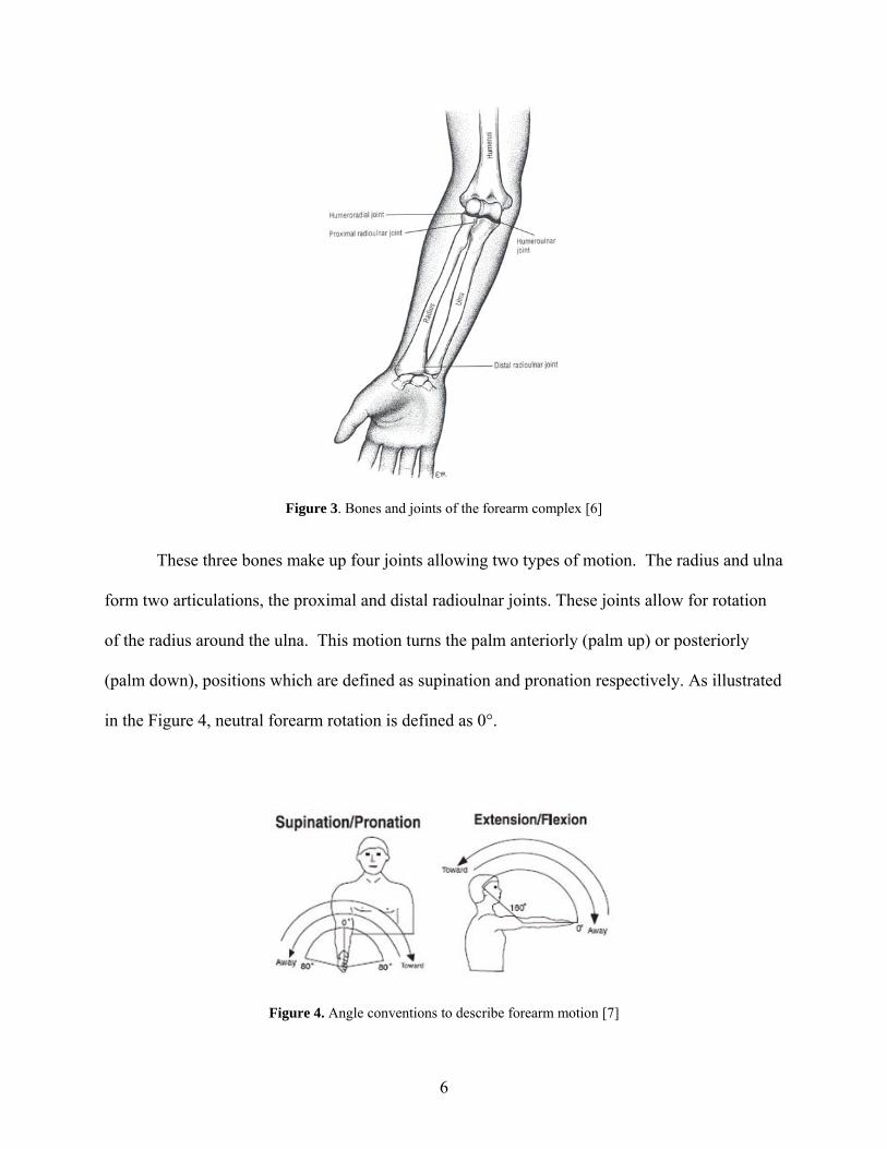
Figure 3. Bones and joints of the forearm complex [6]
These three bones make up four joints allowing two types of motion. The radius and ulna
form two articulations, the proximal and distal radioulnar joints. These joints allow for rotation
of the radius around the ulna. This motion turns the palm anteriorly (palm up) or posteriorly
(palm down), positions which are defined as supination and pronation respectively. As illustrated
in the Figure 4, neutral forearm rotation is defined as 0°.
Figure 4. Angle conventions to describe forearm motion [7]
6

The radius and ulna each form an articulation with the humerus. The proximal end of the
ulna forms a large concave bony process known as the trochlear notch. The notch fits in a
groove of the cylindrically shaped process on the distal humerus called the trochlea. The head of
the radius is cup shaped and articulates with the rounded ball shaped process on the distal
humerus called the capitulum. These joints allow the angle between the humerus and forearm to
decrease (flexion) or increase (extension). For flexion/extension, the fully extended arm is the 0°
reference as illustrated in Figure 4. Figure 5 shows the locations of the different bony structures
of the radius, ulna, and humerus.
Figure 5. Bony structures and muscle attachments of the forearm (anterior view) [6]
7

Numerous muscles are involved in powering the motion of the elbow. Based on the
motion that the muscle force facilitates, a muscle can serve as a flexor, extensor, supinator, or
pronator. The main elbow flexors are the brachialis, biceps brachii, brachioradialis, and pronator
teres. The triceps brachii and anconeus provide force for elbow extension. Forearm supination
is powered by the biceps brachii and the supinator muscle, while the pronator quadratus and
pronator teres power pronation. Figures 6 and 7 illustrate the location of each muscle.
Figure 6. Location of forearm muscles (Anterior view) [8]
8

Figure 7. Location of forearm muscles (Posterior View) [8]
2.3 BICEPS BRACHII As mentioned above, the biceps brachii muscle functions as an elbow flexor and as the dominant
supinator of the forearm. Proximally, the biceps originates from two points, the supraglenoid
tubercle and the coracoid process of the scapula. The distal biceps tendon inserts onto the radial
(bicipital) tuberosity as shown in Figure 5. The radial tuberosity is a crescent shaped bony
protrusion on the medial side of the proximal radius. The tendon inserts on the posterior ulnar
side of the tuberosity. The distal biceps tendon rotates the radius about the ulna around an axis
that extends through the center of the radial head and ulnar head. Figure 8 shows the position of
the radius as the arm supinates.
9

Figure 8. Rotation of the radius (green) around the ulna during supination
As the forearm pronates, the distal biceps tendon wraps around the tuberosity creating a
cam-like effect. The added height of the tuberosity compared to the shaft of the radius is thought
to place the biceps tendon in a more efficient position to supinate the forearm [9].
2.4 DISTAL BICEPS RUPTURES The rupture of the distal biceps tendon is a relatively uncommon injury occurring only in 1.2 of
100,000 patients [10]. The injury usually occurs in the dominant arm of 40-50 year old males
from eccentric loading of the supinated forearm such as during lifting activities [10-12]. Most
patients note a single traumatic event followed by pain that gradually subsides.
10

Figure 9. Illustration of a distal biceps rupture [13]
During complete tears, a deformity in the biceps contour could occur [14]. Patients
usually present with swelling of the forearm along with weakness in supination [11]. Smoking
has been found to increase the risk of distal biceps rupture by nearly 8% [10]. Additionally,
mechanical impingement could possibly contribute to the occurrence of rupture. It has been
shown that the space between the radial tuberosity and ulna border decreases by 50% from full
supination to full pronation [15].
Figure 10. Deformity after rupture of right biceps treated non-operatively (Left). Normal contra lateral side
(Right).[2]
11

2.5 SURGICAL TREATMENT OVERVIEW The surgical treatment of the ruptured distal biceps tendon has evolved over the past century.
Early surgical attempts to reinsert the biceps tendon to the radial tuberosity using an anterior
approach were met with numerous complications[16, 17]. In 1941, Dobbie concluded that an
anterior approach was “impractical and unwise” due to the numerous nervous and vascular
structures of the proximal forearm near the tuberosity [16]. For this reason, some physicians
opted for a simplified non-anatomic repair of suturing the biceps tendon to the brachialis [16,
17]. In 1960, Boyd and Anderson developed a two incision approach for reinserting the biceps
tendon to the tuberosity as an alternative to the anterior approach [18]. In this approach, using a
limited anterior incision, the tendon is passed between the ulna and radius while the forearm is
pronated as shown in Figure 11.
Figure 11. Biceps tendon passed between ulna and radius during Boyd Anderson approach.[18]
A second incision along posterolateral aspect of the elbow exposes the tuberosity for
reattachment. The tendon is passed through a bone flap made on the tuberosity and sutured into
12
place. Boyd and Anderson claimed that this repair was safer and would restore the biceps as a
dominant supinator of the forearm, unlike the brachialis attachment method [18].
With the advent of modern testing equipment to objectively evaluate patient strength, the
efficacy of the different biceps repair techniques could be evaluated. In 1985, Morrey had one
patient that was treated with the brachialis attachment method. Testing showed that the repair
resulted in a 50% loss in supination strength [12]. Years later, others would report the same
deficiency in supination using this method [19, 20]. These findings confirmed the claim made
by Boyd and Anderson over twenty years earlier and provided further cause for anatomic repair.
Baker and Bierwagen had a series of thirteen patients, three of whom were treated
nonoperatively, undergo follow-up isokinetic muscle testing. Their study concluded that the
Boyd-Anderson technique produced satisfactory results in returning normal elbow function to
the patient, while conservative treatment led to weakness in strength and endurance [3]. Others
have also shown similar results using the Boyd-Anderson technique by way of isokinetic testing
[21].
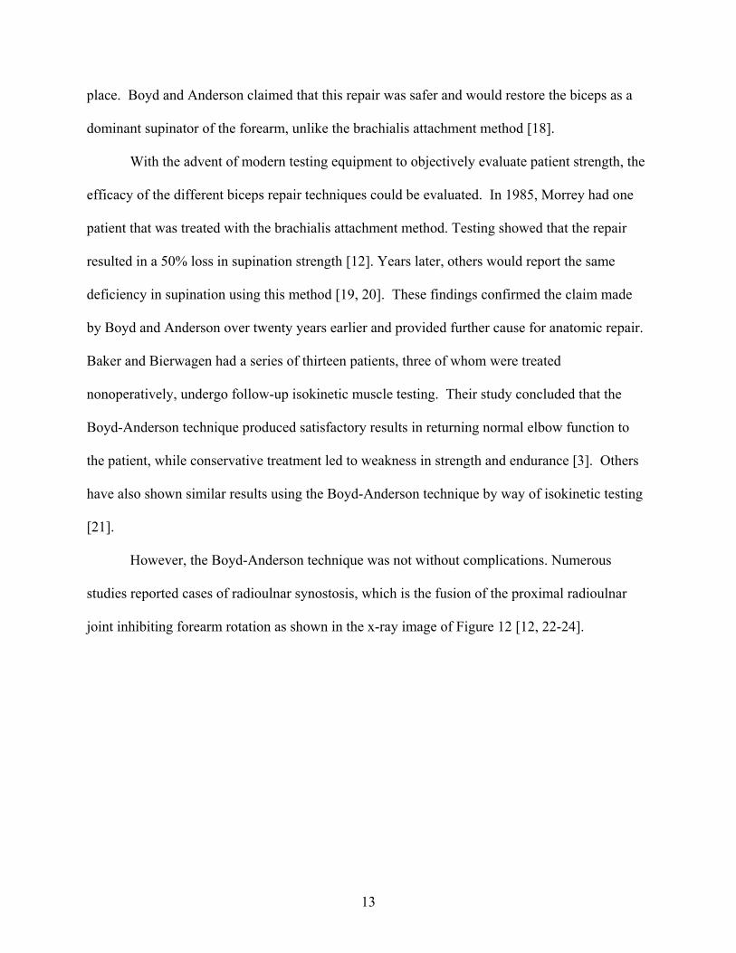
However, the Boyd-Anderson technique was not without complications. Numerous
studies reported cases of radioulnar synostosis, which is the fusion of the proximal radioulnar
joint inhibiting forearm rotation as shown in the x-ray image of Figure 12 [12, 22-24].
13
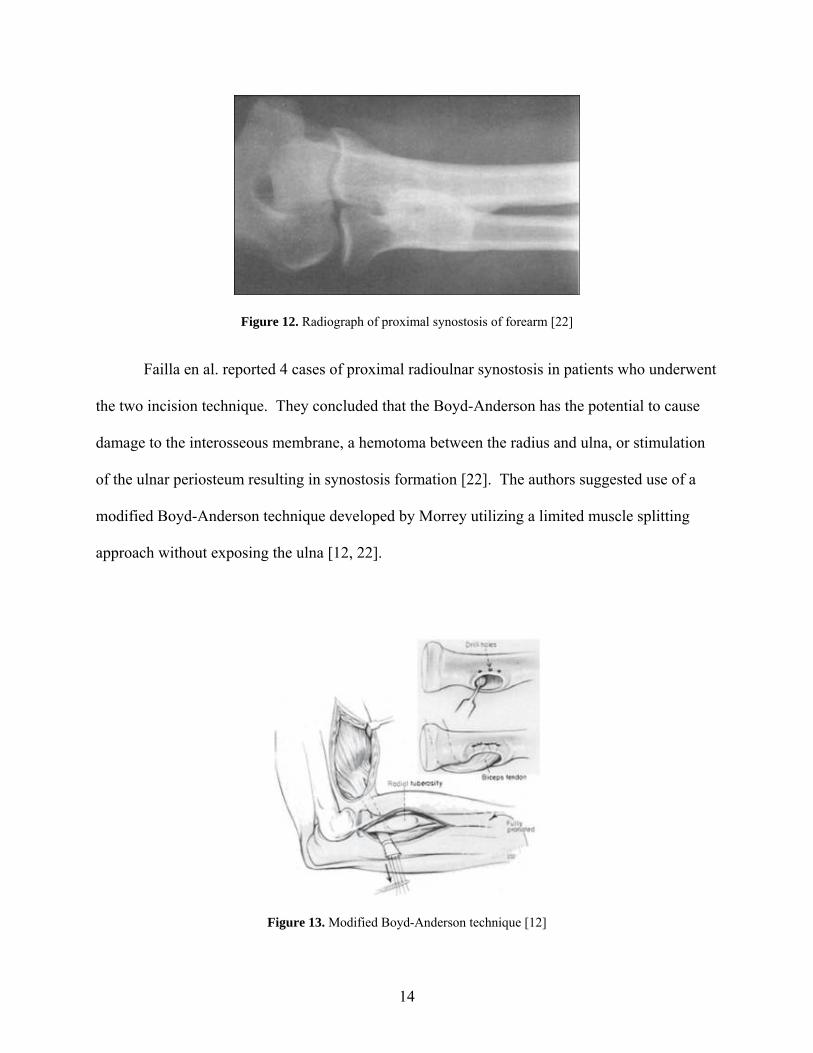
Figure 12. Radiograph of proximal synostosis of forearm [22]
Failla en al. reported 4 cases of proximal radioulnar synostosis in patients who underwent
the two incision technique. They concluded that the Boyd-Anderson has the potential to cause
damage to the interosseous membrane, a hemotoma between the radius and ulna, or stimulation
of the ulnar periosteum resulting in synostosis formation [22]. The authors suggested use of a
modified Boyd-Anderson technique developed by Morrey utilizing a limited muscle splitting
approach without exposing the ulna [12, 22].
Figure 13. Modified Boyd-Anderson technique [12]
14

In a series of 74 patients, Kelly reported no instances of radioulnar synostosis using this
modified Boyd-Anderson technique [25]. This approach was shown to produce satisfactory
results in both dominant and non-dominant arms [11]. However in more recent literature, Bisson
reported a higher complication rate (27%) including 3 cases of radioulnar synostosis (7%) using
the modified Boyd-Anderson [26].
In 1993, Barnes published a method for reattachment of the tendon using Mitek anchors
and a one incision anterior approach. The 4 patients in the series had satisfactory outcomes with
no complications. Barnes attributed the lack of complications to the minimal exposure and
drilling needed to place the anchors [27]. Le Heuc (1996), Balabaud (2004), and Kahn (2008)
were able to produce satisfactory results using this technique, which provided further evidence in
favor of minimally invasive anterior approaches [19, 28, 29].
In 1998, Strauch published a technique that used 2.5 mm Statak suture anchors with a
single zigzag anterior incision [30]. Lynch later had successful outcomes by combining the
Boyd-Anderson technique with Mitek suture anchor fixation [31].
In 2000, Pinto published a paper advocating the use of a single incision anterior
technique [32]. That same year, Bain adapted the Endobutton fixation used in ACL
reconstruction to a single incision anterior technique for distal biceps repair [33]. The technique
provided strong fixation to allow for early mobilization, while simplifying the fixation method
for the surgeon [34]. The Endobutton procedure has been shown by many published studies to
produce satisfactory results [35-37].
15

Figure 14. Bain’s biceps fixation with Endobutton [33]
With many types of tendon anchoring devices in use, distal biceps research shifted
towards biomechanical evaluations of the fixation strength of the repair. Early studies found that
bone bridge fixation was stronger and stiffer compared to suture anchors [38]. However, these
findings were contradicted in later studies. In 2003, Greenberg et al conducted a cadaveric study
that tested three anchoring methods: Mitek Superanchor, conventional bone bridge, and the
Endobutton. The Endobutton was found to provide the greatest pull out strength followed by the
Mitek anchors [34]. Lemos compared the strength of bone bridge and Mitek anchors and found
that the Mitek anchors were superior [39]. Idler compared the bone bridge and interference screw
techniques. They found that the interference screws provided equivalent strength to the native
tendon [40]. In 2006, Spang directly compared the Endobutton to suture anchors. The results of
the study indicated that the Endobutton did not have statistically significant biomechanical
advantages over suture anchors [41]. In a study that compared 13 different fixation methods, the
Endobutton was found to have the highest load to failure, but noted that all fixation methods
provided adequate strength [42]. Similar results were found in other studies that compared the
Endobutton to other fixation methods [43, 44].
16

2.6 PREVIOUS WORK ON BICEPS MOMENT ARM A muscle’s moment arm can be used as a measure of the torque generating ability of a particular
muscle about a joint. Numerous studies have shown that the moment arm changes with joint
angle. In 1995, Murray showed that the moment arms of the major elbow muscles of both a
male and female cadaver varied as a function of elbow flexion angle and forearm rotation angle.
In this study, the moment arms were derived by taking the derivative of the 3rd order polynomial
best fit curve of the tendon displacement and joint angle data. For the biceps, their testing
showed the maximum moment arm (≈ 11 mm) occurred at approximately neutral with the arm
flexed to 85° [45].
In 2001, Haugstvedt used a dynamic simulator to load the supinators and pronators of the
forearm. The simulator included a torque sensor, positional sensors, and pneumatic actuators for
muscle loading. With the elbow fixed at 90° of flexion, each muscle was ramp loaded while the
torque generated was recorded. Each muscle was tested in 10° increments over the full forearm
range of motion. The moment arm at each forearm position was calculated from the slope of the
torque vs. load relationship. Their results showed that the biceps is the dominant supinator with
a maximum moment arm occurring in a slightly pronated position [46]. Figure 15 shows a plot
of the results.
17

Figure 15. Moment arm (cm) data from Haugstevdt. [46]
2.7 PREVIOUS WORK ON THE EFFECT OF ATTACHMENT LOCATIONS Only one study was identified in the medical literature that tried to examine the effect that
reattachment location has on the biceps [47]. Henry et al used a static weight (100 N) to load the
biceps and measured the supination force generated in pairs of matched cadaveric elbows with a
load cell. The elbow was fixed a 90° of flexion and one end of a ¼” pin was placed in the distal
radius. The other end of the pin was placed parallel to an axial load cell to measure the resultant
force when the biceps was loaded. The native tendon was tested first as a baseline. Then the
distal biceps was transected and tested after repair using an anterior attachment site on the
tuberosity. In the contra lateral arm, the testing was repeated using a posterior attachment site.
Their data showed that there was no significant difference in the supination force
generated between the anterior and posterior insertions. However, the study had several
limitations that need to be considered. First, one major limitation was that the cadaveric elbows
18

were only tested in neutral rotation, so the behavior throughout the range of motion is unknown.
Second, torque was not measured directly. The torque values reported were derived quantities
based on the length of the pin. The study did not mention any systematic identification of the
attachment sites across all the specimens leaving very little anatomic insight to the orthopaedic
surgeon. Lastly, the surgical techniques required some burring of the tuberosity, which may
have significantly altered the geometry of the radial tuberosity. This limitation narrows the focus
of the study down to a comparison between two surgical techniques as opposed to a more in
depth biomechanical analysis of insertion site location.
19

3.0 PRELIMINARY ANALYSIS Because of the limited information in the literature, there is little understanding to the effect of
tendon attachment location on the biceps. Due to the availability and cost of cadaveric
specimens, it was important to try to estimate the effect size to examine whether it could possibly
have clinical significance before starting biomechanical testing. A preliminary analysis was
conducted to estimate the bicep supination moment arm of varying attachment locations over the
range of motion of the forearm. This was achieved by using spatial data from Magnetic
Resonance Imaging (MRI) to create a virtual model of the radius and calculating the moment
arm at discrete angles in a matlab based simulation.
3.1 MRI IMAGING The author of this thesis voluntarily underwent MRI imaging of the right forearm. Imaging of
the distal biceps was done using the flexed abducted supinated (FABS) view as described by
Giuffrè and Moss [48]. In this position, the person lies on their stomach with the fully supinated
arm flexed to 90° and placed above the head. Sand bags were used to help stabilize the arm and
prevent movement during imaging. Sequences of images of the forearm were taken in the
coronal and sagittal views.
20

3.2 DICOM MRI images are saved in a Digital Imaging and Communications in Medicine (DICOM) file
format. This format provides a set of standards for the information contained in a medical image.
Manufacturers of imaging equipment provide a certificate of DICOM compliance for their
equipment. Embedded in the attributes of the file is key information regarding patient
information, image position, and pixel settings. These attributes allow for the spatial mapping of
pixels in a DICOM image.
3.3 PREPROCESSING The MRI images were imported into Mimics software (Materialise, Leuven, Belgium). Mimics
allows the user to process 2D image data and reconstruct accurate 3D models of the data. Mimics was
primarily used for extracting points on bone surface geometry as well as key anatomic points. Using the
segmentation and curve fitting tools, a sliced point cloud of pixels representing the surface of the
proximal radius was created. The centerline tool was used to define the pixels at the center of radial head
and center of ulnar head. Pixels were also chosen to represent different possible insertion points of the
distal bicep tendon. The pixel and image data was then exported as a text file and imported into a
formatted excel spreadsheet to allow for processing in Matlab R2009a (MathWorks, Natick,
Massachusetts). The pixel data was loaded into a Matlab program that spatially maps each pixel
following the transformation provided in PS 3.3 2007 of the DICOM Standards and outputs a
dataset of xyz coordinates. The details of the program can found in Appendix A.
21
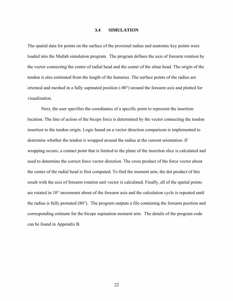
3.4 SIMULATION The spatial data for points on the surface of the proximal radius and anatomic key points were
loaded into the Matlab simulation program. The program defines the axis of forearm rotation by
the vector connecting the center of radial head and the center of the ulnar head. The origin of the
tendon is also estimated from the length of the humerus. The surface points of the radius are
oriented and meshed in a fully supinated position (-80°) around the forearm axis and plotted for
visualization.
Next, the user specifies the coordinates of a specific point to represent the insertion
location. The line of action of the biceps force is determined by the vector connecting the tendon
insertion to the tendon origin. Logic based on a vector direction comparison is implemented to
determine whether the tendon is wrapped around the radius at the current orientation. If
wrapping occurs, a contact point that is limited to the plane of the insertion slice is calculated and
used to determine the correct force vector direction. The cross product of the force vector about
the center of the radial head is first computed. To find the moment arm, the dot product of this
result with the axis of forearm rotation unit vector is calculated. Finally, all of the spatial points
are rotated in 10° increments about of the forearm axis and the calculation cycle is repeated until
the radius is fully pronated (80°). The program outputs a file containing the forearm position and
corresponding estimate for the biceps supination moment arm. The details of the program code
can be found in Appendix B.
22

3.5 RESULTS Figure 16 shows the moment arm estimates vs. forearm position curves for five different
insertion locations. The results show that as the insertion is moved lateral on the anterior radius,
the supination moment arm was lower while in the supinated forearm. However, as the arm
pronates, the moment arms were equivalent for all repairs. According to these estimates, moving
the insertion anterior can create up to a 25% loss in moment arm. The orthopaedic surgeons
collaborating on this project concluded that a loss of this size could potentially be clinically
relevant especially in biceps repaired using an anterior approach. Based on these estimates, it
was decided to proceed with a cadaveric biomechanical study.
Figure 16. Moment arm estimates vs. forearm position curves for five different insertion locations
23

4.0 METHODS
4.1 PROJECT OVERVIEW Isometric supination torque and range of motion were measured using 6 cadaveric specimens.
The specimens were mounted in an elbow simulator, which consisted of a computer controlled
linear actuator to exert known bicep loads. For torque testing, the forearm was rotated and
locked into three positions: 60° pronation, neutral and 60° supination. The biceps tendon was
loaded, and the torque generated was measured with an attached sensor for the native tendon
attachment. The tendon insertion site was then transected, reattached, and tested at 4 different
locations. The torque vs. load data was plotted to determine the bicep moment arm for each
tendon attachment. Range of motion testing was performed by unlocking the radius and
incrementally loading the biceps. The forearm motion for the native tendon and each location
was measured using a digital goniometer. A two-way repeated measures analysis of variance
with Tukey’s post-hoc testing was used for statistical analysis.
4.2 CADAVERIC SPECIMENS
A total of 6 frozen upper extremity cadaveric specimens (5 male), with an average age of 60 (36-
83) years, were used. The specimens included the full forearm from the hand to the mid-
humerus proximally. Specimens with medical histories of rheumatoid arthritis, degenerative
joint disease or any orthopaedic anomaly were excluded. One specimen was replaced because it
24
was unable to pronate past 30°. Prior to the day of testing, each specimen was allowed to thaw
overnight at room temperature and kept moist with normal saline.
4.3 TESTING APPARATUS
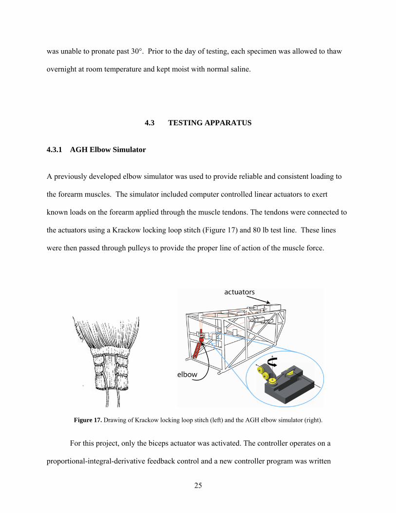
4.3.1 AGH Elbow Simulator A previously developed elbow simulator was used to provide reliable and consistent loading to
the forearm muscles. The simulator included computer controlled linear actuators to exert
known loads on the forearm applied through the muscle tendons. The tendons were connected to
the actuators using a Krackow locking loop stitch (Figure 17) and 80 lb test line. These lines
were then passed through pulleys to provide the proper line of action of the muscle force.
Figure 17. Drawing of Krackow locking loop stitch (left) and the AGH elbow simulator (right).
For this project, only the biceps actuator was activated. The controller operates on a
proportional-integral-derivative feedback control and a new controller program was written
25

specifically for this project. The program sends a sinusoidal reference signal to the biceps
actuator. For the first 100 samples, the reference signal was set to a constant 1 lb load to remove
any slack from the system. For the next 600 samples, the input was a sinusoid with amplitude of
14 lbs. The last 100 samples returned the load to a constant 1 lb load. Figure 18 shows the
graph of the resulting biceps load output.
B iceps Loading P rofile
02468
10121416
0 100 200 300 400 500 600 700 800
S a m ple s
Load
(lbs
)
Figure 18. Biceps loading profile.
The 15 lb maximum bicep load was chosen based on data in the medical literature.
Greenberg et al showed that the mean biceps force needed to flex 15 cadaver arms to 130° was
67 N (≈15 lbs) [34]. For this reason, 15 lbs was determined to be a reasonable approximation of
the physiological loading that could occur. The entire code for the program is included in
Appendix C.
26

4.3.2 Supination Torque Device
A device capable of measuring isometric forearm torque in cadaveric specimens was developed
to attach to the existing elbow simulator assembly. During previous work on this device, an
80/20 aluminum channel with turnbuckle style support system was retrofit to the front of the
elbow simulator frame as shown in Figure 19.
Figure 19. Existing support structure retrofit to elbow simulator.
The aluminum channel supported a carriage with a torque sensor that could translate and
lock into place. To align the sensor with the forearm axis of rotation, an additional piece of
aluminum channel was mounted perpendicularly to the first channel. Also, a shoulder bolt was
placed through the center of the carriage plate to allow for rotation.
To transmit the supination torque of the forearm, a torsional load transfer plate with a slot
machined through the center was bolted to the torque sensor. A flat was machined into a shaft
such that it would fit into the transfer plate slot. Next, an aluminum friction clamp attached to
the load cell shaft. The friction clamp allowed the assembly to rotate and lock into different
27

positions about the load cell axis. An aluminum plate with a pattern of holes was fabricated such
that it could be bolted to the distal radius. Next an adjustable shaft with a universal joint was
used to connect the plate to the load cell shaft clamp. The final assembly allowed the forearm to
rotate and lock into different supination/pronation angles and it offered enough flexibility and
adjustment to handle the natural variability found among cadaveric specimens.
Figure 20. Final assembly of testing apparatus.
28
4.4 DATA ACQUISITION SETUP To determine the moment arm, the torque and biceps load data needed to be captured
simultaneously. The torque sensor and biceps load cell outputs were connected to an NI-
6008USB A/D converter. The sample rate for the A/D converter was set to 60 Hz to match the
sample rate of the torque sensor signal conditioner. The converter was connected to a separate
laptop with Matlab R2008a. A program was written in Matlab to acquire the data and to provide
real-time plotting of the supination torque and biceps load during testing. A copy of the code can
be found in Appendix D.
4.5 TORQUE TEST PROTOCOL
Each specimen was mounted in the elbow simulator with the humerus and ulna fixed firmly to
the frame at 90° of flexion. The proximal end of the distal biceps tendon was attached to an
actuator using 80 lb test line. The adjustable shaft was attached to the distal radius plate. The
forearm was then rotated and locked into each of three positions: 60° supination, neutral and 60°
pronation. The biceps tendon was loaded to 66.75 N (15 lbs), and the torque was measured for
the native tendon attachment. The distal biceps tendon was transected, and surgically reattached
using a cortical button and then tested at each of the four different locations. A modified cortical
button fixation was well-suited for the tests because it did not compromise the radius bone of the
specimen. Also, this type of fixation is the preferred method by the senior orthopaedic surgeon.
For each forearm position, each test was repeated three times.
29

4.5.1 Tendon Attachment Locations
With the arm fully supinated, the borders of the radial tuberosity were identified, and the lines
marking the proximal and distal border were drawn. The borders were defined at the points
where the bone geometry of the radius begins to exhibit slight concave curvature. The length of
the tuberosity borders was measured and their midpoints were marked. A line connecting the
two midpoints defined the center axis line. The highest point (apex) on the tuberosity at the
tendon-bone interface was identified using calipers. A medial to lateral line, parallel to the
tuberosity border lines, was drawn to define the apex diameter line.
Proximal Anatomic (PA)
Figure 21. Diagram of distal biceps tendon reattachment locations.
Using these markings as a guide, three drill holes (2.25 mm diameter.) were
systematically placed in the radius. Location anatomic (A) was placed on the apex diameter line
at the native tendon insertion. Location anterior center axis (ACA) was drilled at the intersection
of the center axis and apex diameter lines. Location posterior center axis (PCA) is the same as
Anterior Posterior
Proximal Border Line
Distal Border Line
Apex Diameter Line
Center Axis Line Anatomic (A)
Posterior Center Axis (PCA)Anterior Center
Axis (ACA)
30

anterior center axis except that the tendon wrapped around the tuberosity and attached on the
posterior side of the radius. Location proximal anatomic (PA) was drilled at the most ulnar point
on the proximal borderline. This systematic approach based on the radius geometry for
identifying the insertion sites allowed for consistent placement across all specimens.
4.5.2 Mathematical Background Mathematically, torque,τv , is represented by the cross product of the force vector, , and the
position vector,
Fv
rv , shown in Equation 1.
Frvvv ×=τ (1)
The position vector, rv , is a vector from a point on the axis of interest to the point where the
force is applied. By definition, the magnitude of the cross product of rv and can be written as: Fv
θτ sin⋅⋅= Frvvv
(2)
Where,
τv =magnitude of the torque, τv
rv =magnitude of the position vector, rv
Fv
=magnitude of the force vector, Fv
θ =angle between rv and Fv
31

The perpendicular distance between the moment axis and the line of action of the force
defines the moment arm, , and its magnitude is given by the d θsin⋅rv term in equation 2. By
rearranging Equation 2, the moment arm can be calculated as shown by:
θτ
sin⋅== rF
d vv
v
(3)
Mathematically, Equation 3 illustrates that one would expect a linear relationship since
the distance from the axis, rv , and the angle θ remain constant at fixed forearm rotation
positions. As it relates to supination torque, the only times these parameters can change is when
either the forearm rotational position or the insertion site location is changed. Therefore, if the
moment arm, , remains constant, then the torque will have a direct relationship with the force,
i.e. torque increases as force increases or vice versa, and will be scaled by a factor equal to the
moment arm.
d
For this study, the magnitudes of the supination torque and biceps load were measured
simultaneously. We tested all tendon attachment locations at the same forearm rotational
positions under the same biceps muscle loading profile. By comparing the moment arms for
each attachment location at a given forearm rotation position, the effect of the attachment
location could be determined. Therefore, any change in the torque generated was due to a
change in the muscle moment arm resulting from varying the attachment location.
A linear regression line was fitted to the supination torque vs. bicep load data for each
torque test as shown by Figure 22. The moment arm for each tendon attachment was defined as
the slope of the regression line. The moment arm was averaged over the three repeated tests
taken at each forearm position. A positive moment arm value indicated that the biceps generated
a supination torque.
32

4.6 SUPINATION MOTION TEST The humerus and ulna were firmly fixed at 90° of flexion. The only degree of freedom allowed
was forearm rotation. A line was drawn on the distal radioulnar joint (DRUJ) through the radial
and ulnar styloids. This line was used to define the forearm’s rotational position with a digital
goniometer. It was hypothesized by the investigators that a more efficient attachment would
supinate the arm more under the same load when compared to the others. With no load on the
biceps tendon, the arm was placed in pronation. The biceps was then loaded incrementally from
0 N to 22.25 N (5 lbs), 44.50 N (10 lbs), and then 66.75 N (15 lbs), and the forearm position was
measured. The test was repeated three times for each biceps tendon attachment location.
4.7 DATA ANALYSIS
4.7.1 Filtering Data Supination torque and biceps load data were filtered using a lowpass Butterworth filter in
Matlab. Filter parameters were adjusted until a smooth curve was achieved. The matlab code is
included in Appendix E.
4.7.2 Statistical Methods – Torque Data A linear regression line was fitted to the torque vs. load data for each test as shown by Figure 3.
The moment arm for each tendon attachment was defined as the slope of the regression line. The
33

moment arm was averaged over the three tests taken at each position. A positive moment arm
value indicated that the biceps generated a supination torque.
Figure 22. Example of torque vs. biceps load relationship for native tendon.
A two-way repeated measures analysis of variance was used to determine if tendon
location and forearm position significantly affect the moment arm of the biceps (p <0.05).
Tukey’s post-hoc testing was used to compare the means of individual treatment levels with one
another.
4.7.3 Statistical Methods – Supination Motion Data
A two-way repeated measures analysis of variance was used to determine if tendon location and
biceps load significantly affected the moment arm of the biceps (p <0.05). Tukey’s post-hoc
testing was used to compare the means of individual treatment levels with one another.
34

5.0 RESULTS
5.1 GROSS OBSERVATIONS The native biceps tendon appeared to insert normally in all specimens. Each native tendon
inserted slightly posterior of the most ulnar edge of the tuberosity in a ribbon-like fashion. At
60° supination, minimal wrapping of the tendon around the apex of the tuberosity was observed.
As the forearm was pronated, an increase in tendon wrapping was observed with definitive
wrapping occurring just before neutral. Location anatomic exhibited a similar wrapping
behavior.
For location anterior center axis, minimal tendon wrapping was observed at all three
forearm positions due to the centralized placement of the repair. Slight wrapping may have
occurred at near full pronation of the forearm which is a comparably larger angle than observed
in the native case.
For posterior center axis, tendon wrapping was observed at all three forearm positions. At
this location, the tendon was acting over the apex of the tuberosity at all times.
For the proximal anatomic location, minimal wrapping occurred at 60° supination. As
the forearm pronated, the tendon wrapped around the proximal junction of the tuberosity and
radial shaft.
35

5.2 MOMENT ARM RESULTS Analysis showed that tendon location and forearm position significantly affected the moment
arm of the biceps (p<0.05). The native tendon had a mean moment arm of 5.67 ±2.86, 10.44
±1.45 and 8.04 ± 1.25 (mm) in 60° supination, neutral and 60° pronation respectively. Our native
tendon moment arm data compares well with other findings published in the medical literature
which provides some validity to the methods used [45, 46]. Murray et al reported an estimate of
13 mm for the biceps moment arm of males at neutral. From the plots published by Haugstvedt,
the average moment arms were approximately 2.5, 11, 10 mm for 60° supinated, neutral, and 60°
pronated respectively. This data is comparable to the average native moment arm values of 5.7,
10.4, and 8.0 mm found in this study.
Reattachment to an anatomic location in all forearm positions respectively (6.24 ±3.30,
10.41±2.03, 8.41±1.22) showed no significant difference from the native insertion. Location
anterior center axis had a moment arm which was significantly lower in supination (0.15 ±3.48)
and neutral (7.65 ±1.95) compared to the native insertion, while no difference was found in
pronation (8.26 ±1.88). In two specimens, this position created a pronation torque at 60° of
forearm supination.
Location posterior center axis was significantly higher in supination (7.21± 3.02)
compared to the native, however no differences were found in neutral and pronated positions.
Location proximal anatomic trended to have a lower moment arm than the native in all
forearm positions, but was only significantly different in neutral (8.83±2.06). In supination,
location proximal anatomic’s moment arm was 4.69 ±2.75 which was significantly higher than
location center axis. No difference was observed between all tendon locations in pronation.
36

Figure 23. Summary of results for moment arm vs. forearm position.
All of the results are summarized in Figure 23 as well as in Appendix F.
5.3 SUPINATION MOTION RESULTS Analysis showed that tendon location and biceps load significantly affected the supination
motion of the biceps (p<0.05). The native tendon produced 68°±9°, 71°±9°, and 73°±10° of
supination motion at 22.25 N, 44.50 N, and 66.75 N respectively. Location anatomic was not
significantly different than the native tendon producing 70°±10°, 74°±10°, and 75°±11° at each
level respectively. At 44.50 N, and 66.75 N, location anterior center axis was significantly lower
than the native tendon (59°±17°, 62°±16°, and 62°±16°). No significant differences were found
for the other locations. At 22.25 N, 44.50 N, and 66.75 N, location posterior center axis was
significantly higher than the native tendon (74°±8°, 78°±8°, and 80°±8°). Location proximal
37

anatomic was not significantly different than the native tendon producing 68°±11°, 71°±10°, and
73°±9° at each level respectively.
Figure 24. Summary of results for supination motion vs. biceps load.
All of the results are summarized in Figure 24 as well as in Appendix F.
38

6.0 DISCUSSION The supination torque generated by the bicep tendon is a function of both the contractile force of
the biceps muscle and the tendon’s moment arm. During repair of ruptured distal bicep tendons,
the surgeon’s goal is to restore preinjury function. The patient’s bicep muscle force is
predetermined; however, this study showed that tendon reattachment location can influence
supination moment arm by determining what portions of the radius the tendon wraps over during
pronation.
Our native tendon moment arm data compares well with other findings published in the
medical literature which provides some validity to the methods used [45, 46]. Murray et al
reported an estimate of 13 mm for the biceps moment arm of males at neutral. From the plots
published by Haugstvedt, the average moment arms were approximately 2.5, 11, 10 mm for 60°
supinated, neutral, and 60° pronated respectively. This data is comparable to the average native
moment arm values of 5.7, 10.4, and 8.0 mm found in this study.
The study showed that reattachment of the distal bicep tendon to its anatomic position
showed no difference in moment arm to the native. Radializing the attachment, location anterior
center axis, resulted in a significantly lower moment arm than the native in neutral (-27%) and
supinated (-97%) positions with the greatest difference being in supination. We believe this
observation is caused by the loss of the biceps tendon wrapping around the tuberosity. As the
forearm pronates, the tendon can only wrap around anterior portions of the radius that are radial
to the insertion site as shown by Figure 25. Therefore, for location anterior center axis, the
tendon will never act over the added height of the tuberosity effectively reducing the moment
39
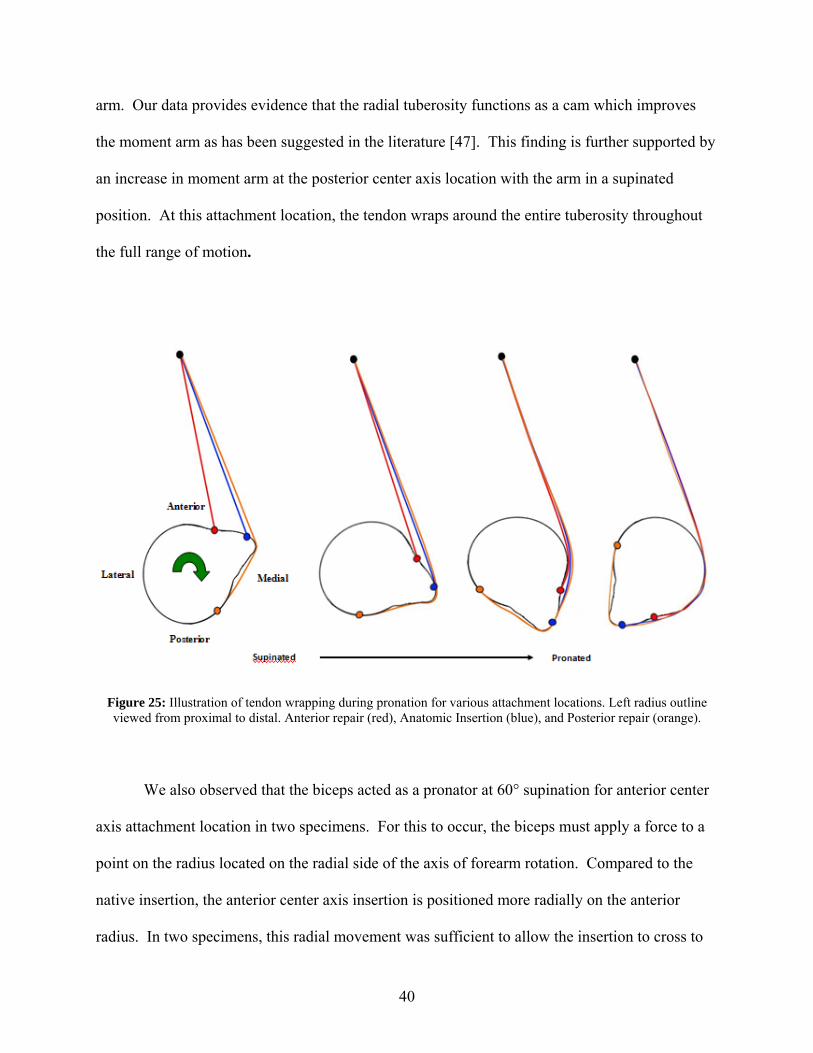
arm. Our data provides evidence that the radial tuberosity functions as a cam which improves
the moment arm as has been suggested in the literature [47]. This finding is further supported by
an increase in moment arm at the posterior center axis location with the arm in a supinated
position. At this attachment location, the tendon wraps around the entire tuberosity throughout
the full range of motion.
Figure 25: Illustration of tendon wrapping during pronation for various attachment locations. Left radius outline viewed from proximal to distal. Anterior repair (red), Anatomic Insertion (blue), and Posterior repair (orange).
We also observed that the biceps acted as a pronator at 60° supination for anterior center
axis attachment location in two specimens. For this to occur, the biceps must apply a force to a
point on the radius located on the radial side of the axis of forearm rotation. Compared to the
native insertion, the anterior center axis insertion is positioned more radially on the anterior
radius. In two specimens, this radial movement was sufficient to allow the insertion to cross to
40
the radial side of the forearm axis at 60° supination. However, as the forearm pronated, the
insertion crosses back over to the ulnar side of the axes and acted as a supinator in neutral and
60° pronation.
Henry et al measured the resultant supination force generated by eleven pairs of
cadaveric arms in neutral forearm position using both an anterior and posterior repair method
[47]. For the anterior group, the biceps was sutured to the anterior tuberosity using a cortical
bone bridge on the posterior tuberosity [49]. Posterior reattachment was done using the modified
Boyd-Anderson approach [12]. An incision along posterolateral aspect of the elbow exposes the
posterior tuberosity. The tendon is passed between the ulna and radius while the forearm is
pronated, and a cortical window is burred into the tuberosity. The tendon is seated into the cavity
and sutured into place using a bone bridge.
Their findings showed no significant difference between the two repairs. Some
limitations of the study were that the arms were only tested in neutral and that muscle moment
arms were not measured. Studies have shown that the biceps moment arm could change
nonlinearly with forearm position making conclusions of the behavior throughout the entire
range of motion difficult from one position. Also, both surgical techniques that were being
compared required some burring of the tuberosity which may have significantly altered the
geometry of the radial tuberosity making it difficult to isolate just the effect of attachment
location alone.
The cortical button technique used in this study allowed examination of the effect of
attachment location without drastically changing the native radius morphology and provided
insight into the significance of the geometry. The effect of creating a cortical window in the
tuberosity during a two incision Boyd-Anderson repair has been previously suggested to
41
decrease the moment arm due to tuberosity height reduction [9]. Our results support the
importance of maintaining the tuberosity height and show that the ideal surgical repair for distal
biceps ruptures would be one that required minimal alterations to geometry of the radius. This
would allow the tendon to wrap over the apex of the tuberosity, and thereby in effect maximizing
the muscle moment arm.
The study further showed that tendon location had no impact on the moment arm at 60°
pronation. As the radius pronates, there is a certain point at which the tendon will begin to wrap
around the radius. For each tendon location, this will happen at a different angle of forearm
rotation. However, the angle when all of the tendon locations begin to experience wrapping, the
moment arms should be almost equivalent. The tendon will be wrapping around the radial side
of the radius which typically has small geometric variation over the length of the tuberosity. At
60° pronation, we believe this angle was surpassed resulting in no difference in moment arms
across all locations. These findings could suggest that patients with a biceps repair might
experience the most weakness in a supinated position without experiencing a deficit in
supination strength in the pronated forearm.
Most of the strength testing in the literature has been done using commercial
dynamometers for isokinetic testing of the biceps with comparisons of peak strength values
usually defined as the maximal torque produced during the range of motion [2, 3, 11, 20, 23, 24,
28, 31, 50-57]. One study found that peak supination torque occurred at 12° of forearm
supination during isokinetic testing of a normal population leading one to believe that the peak
strength measurements in the literature might not be representative of the entire function of the
repair [50]. One weakness of reports with isokinetic testing is that no comparisons are made on
the supination strength differences of patients at different forearm positions other than positions
42

of maximum torque. For this type of muscle testing, it may be difficult to find isolated
supination weakness due to the dynamic nature of the testing.
Some supination isometric testing of bicep patients has been reported, but patients are
most commonly tested at neutral forearm rotation [12, 29, 56, 58-61]. Isometric testing has
shown that after surgical repair, the injured arm regains 87%-93% of the supination strength of
the uninjured arm [58-60]. However, our results suggest testing at more forearm positions
especially in supination is warranted. We believe that a larger deficit is most likely to be found
in the supinated forearm during isometric testing, especially in biceps repaired without
restoration of the native insertion site. Based on previous supination strength testing protocols in
the literature, the authors feel that a strength deficit in the supinated forearm might be under
reported.
Historically, some literature has shown that patients with distal biceps ruptures may have
reduced supination endurance ranging from 10-65% after repair [2, 20, 23, 24, 31, 52]. With a
compromised supination moment arm, the patient would require greater muscle contraction to
produce the same torque prior to injury which could provide an explanation to the reduced
endurance that has been reported. The muscle moment arm is directly related to the mechanical
advantage of the muscle. In other terms, this means that the larger the moment arm, the higher
the efficiency of the muscle i.e. produces more output for a given input. Based on our findings, a
patient with an anterior center axis repair could potentially have decreased supination endurance
as well as peak torque due to the reduction in moment arm.
We hypothesized that the effect of tendon location would show up not only in comparing
the moment arms directly, but also in comparing the amount of supination motion generated by
the cadavers for a given biceps loads. The higher the moment arm, the more supination motion
43
we expected it to generate. The findings from our supination motion test confirmed that location
anterior center axis is at a mechanical disadvantage compared to the other locations i.e. for the
same biceps input, it produced less supination motion. Whereas, location posterior center axis
had the greatest mechanical advantage and produced the most motion out of all of the tendon
locations. This lends further support for the importance of tendon wrapping.
In chronic or delayed cases of the ruptured distal biceps, tendon/muscle shortening and
adhesion formation can make anatomic restoration of the tendon to the tuberosity difficult [53,
60]. For these cases, the surgeon must choose whether to attempt anatomic repair or to
reconstruct the biceps tendon with a graft [35, 53, 60]. In our study, a proximal anatomic location
represented the scenario where anatomic repair was chosen after the tendon was shortened due to
retraction. The proximal anatomic location trended to have a lower moment arm than the native
in all forearm positions, but was only significantly different in neutral. At this position, only part
of the tendon wraps around the proximal half of the tuberosity not taking advantage of the full
wrapping effect seen in the native case. However, this position could provide more wrapping of
the tendon over the tuberosity than the anterior center axis location. Clinically these findings
would suggest that if the muscle was contracted and the tendon could not be inserted to its native
position then a proximal anatomic position would be better than a more central anterior one.
44

7.0 CONCLUSIONS AND FUTURE WORK
7.1 CONCLUSIONS This biomechanical study provides support for the importance of anatomic restoration of the
native tendon moment arm during the repair of ruptured distal biceps tendons. The surgeon needs
to pay particular attention to the geometry of the tuberosity and be mindful of the location of
tendon reattachment as it could play a critical role in maximizing the functional outcomes of
patients. The study also provides data that shows supination strength testing at multiple positions
throughout the range of motion might be required to evaluate the overall effectiveness of distal
bicep tendon repair methods.
7.2 FUTURE WORK
Future work on this project will include a clinical follow up of patients who had a distal biceps
repair and are more than two years post-operatively. Each patient will sign an IRB approved
informed consent and complete a disabilities of the arm, shoulder, and hand (DASH)
questionnaire. Upon completion of the follow-up appointment, patients will be given an
honorarium for their participation. The medical records will be analyzed to assess co-
morbidities. The patients’ supination strength and endurance will be measured bilaterally using a
custom made electronic testing apparatus, based on a patented hand strength testing device.
45

Strength data will be collected with the forearm placed in three positions: 60° pronated, neutral
and 60° supinated.
The participants will then have a forearm, elbow, and wrist MRI scan. Using the MRI
data, the tendon healing to cortical bone will be verified and its quality graded using a four-point
ordinal scale by two blinded board certified radiologists. Additionally, the location, length,
width and area of the bicep tendonous attachment will be determined using the MRI images.
Finally, a biomechanical analysis based on the MRI imaging will be conducted to determine if
the surgical reattachment location correlates to the stregth measures recorded.
46

APPENDIX A
IMAGE TO SPATIAL COORDINATES PROGRAM
%Program to convert Image Coordinates to MRI Spatial Coordinates %Created by David M. Weir clear all home %Cell Array of Image Data data={ 89.58 90.29 0.00 'Weir,David' '09010512' '02480000' '61869628' ; 55.71 110.57 0.00 'Weir,David' '09010512' '02480000' '61870236' ; 71.64 79.84 0.00 'Weir,David' '09010512' '02480000' '61869740' ; 79.84 4.38 0.00 'Weir,David' '09010512' '02480000' '61869740' ; 76.04 96.31 0.00 'Weir,David' '09010512' '02480000' '61869532' ; }; [r,s]=size(data); n=1; while n<=r %Get image file information name=data(n,4); study_folder=datac; seq_folder=data{n,6}; image_name=data{n,7}; image_file=fullfile(pwd,'DICOM',study_folder,seq_folder,image_name); %Read in Dicom Info of image dicom_info=dicominfo(image_file); %Extract IOP from Dicom Attributes T=dicom_info.ImagePositionPatient; dir_cosines=dicom_info.ImageOrientationPatient; x_cosines=dir_cosines(1:3,1); y_cosines=dir_cosines(4:6,1); z_cosines=cross(x_cosines,y_cosines); %Build Transformation Matrix transformation=vertcat(horzcat(x_cosines,y_cosines,z_cosines,T),[0,0,0,1]);
47

image_pts=[data{n,1},data{n,2},data{n,3},1]'; %Multiply points by transformation matrix xyz_coords=transformation*image_pts; xyz_data(n,1)=xyz_coords(1,1); xyz_data(n,2)=xyz_coords(2,1); xyz_data(n,3)=xyz_coords(3,1); n=n+1; end %save save('weir_keypts.txt','xyz_data','-ASCII')
48

APPENDIX B
MATLAB BICEPS MOMENT ARM SIMULATION CODE
%Distal Biceps Moment Arm Simulation Program %Created by David M. Weir %VARIABLE Description: % AFR: Unit vector along axis of forearm rotation corh to couh % AFRv: vector from corh to couh used for plotting % C: Direction Cosine Matrix % I: Index of maximum for angles array % IC: vector from insertion to contact point c1 % M_O: Moment about the cor h% M_OB: Moment about the AFR % OC: vector from tendon origin to contact point c1 % OCP: vector from contact point c1 to origin_proj % a: row index of min of d % angles: array of angles between all possible combinations of contact points % b: column index of min of d % beta: forearm angle counter for plots % c1: possible contact point 1 % c2: possible contact point 2 % contact: actual contact point % contact_line: line between c1 and c 2% corh: center of radial head % corh_original: center of radial head before it was made (0,0,0) % couh: center of ulnar head % curve_size: number of control points on surface of proximal radius % curves: control points on surface of proximal radius % curves_filename: name of file with radius surface points % d: array of distances between the ins_pt and pts % data: xyz info of keypoints file % data2: data redefined with corh as origin % data_size: number of points in data % f: counter for while loop that ids Contour points of radius at insertion slice % force_direction: unit vector from contact to tendon origin % forearm_start_pos:position arm was scanned at % g: counter for while loop that ids Contour points of radius at insertion slice % heading: plot heading text % humerus: line along humeru s% humerus_length: length of humerus
49

% image_data: array of pixel info from mri images % increments: amount of forearm rotation between MA calculation cycles % ins_dir: perpendicular vector from contact line to insertion % ins_pt: point chosen from imagin to represent insertion % insertion: closest control point to ins_pt % insertion_image: image that contains insertion % j: "angles" while loop counter % k: "angles" while loop counter % key_points_filename: file name with keypoints data % l: number of rows in image data array % lambda: vector along AFR % loa: array with contact and origin pts % m: rows of pts array % mesh_pts: radius points for meshing % n: columns of pts array % name: name of patient % normal: normal unit vector of plane of rotated points % option: determines where to take ins_pt from % orientation: cosine of up_dir and ins_dir vectors % origin: bicep tendon origin % origin_proj: bicep tendon origin projected into insertion plane % patient_last_name:last name of patient % phi: angle between contact point pairs % pts: points from insertion image % q: while loop counter to redefine curve points with corh as origin % r: number of columns in image data % rot_curves: curve points rotated using C % rot_mesh_pts: mesh of rotated curve pts % rot_pts: points on insertion image rotated % sim_name: name for simulation file % t: vertices of triangles of mesh pts % test: determines whether a point is from the insertion image % theta: amount to rotate radius for it to be at -80 % up_dir: perpendicular vector from contact line to origin % v: while loop counter for MA calculation cycle % w: while loop counter to redefine key points with corh as origin % wrap: determines whether wrapping occured (1:Yes, 0:No) % x: x coordinate of key points % x1: min of M_OB % x2: max of M_OB % y: y coordinate of key points % z: z coordinate of key points
50

clear all clc image_data=load('weir_img_data.mat'); %Load Data (File must be in XYZ column format) patient_last_name=input('Patient last name: ','s'); sim_name=input('Name of simulation: ','s'); key_points_filename=horzcat(patient_last_name,'_keypts.txt'); curves_filename=horzcat(patient_last_name,'_curve_data.txt'); data=load(key_points_filename); data_size=size(data); curves=load(curves_filename); curve_size=size(curves); %Estimation of Humerus Length humerus_length=295; %Center of radial head corh=[data(1,1),data(1,2),data(1,3)] ; corh_original=[data(1,1),data(1,2),data(1,3)] ; %Redefine all points with corh as the origin w=1; while w<=data_size(1) data2(w,1)=data(w,1)-corh(1,1); data2(w,2)=data(w,2)-corh(1,2); data2(w,3)=data(w,3)-corh(1,3); w=w+1; end q=1; while q<=curve_size(1) curves(q,1)=curves(q,1)-corh(1,1); curves(q,2)=curves(q,2)-corh(1,2); curves(q,3)=curves(q,3)-corh(1,3); q=q+1; end %Extract Components of Key Points x=data2(:,1); y=data2(:,2); z=data2(:,3); %Center of radial head (note: should be (0,0,0)) corh=[x(1,1),y(1,1),z(1,1)]; %Center of ulnar head couh=[x(2,1),y(2,1),z(2,1)];
51

%Unit vector along axis of forearm rotation crh to cuh AFR=(couh-corh)/norm((couh-corh)); %Origin of biceps origin=data2(3,:)+(humerus_length*(data2(4,:)-data2(3,:))/norm(data2(4,:)-data2(3,:))); %Chosen Position of insertion on tuberosity ("ins_pt" from imaging) option=input('Insertion Point from: 1)Key Points File or 2)Image : '); if option ==1 ins_pt=[x(5,1),y(5,1),z(5,1)]; insertion_image=input('Name of Image with Insertion: ','s'); name=image_data{1,4}; elseif option==2 name=image_data{1,4}; study_folder=image_data{1,5}; seq_folder=image_data{1,6}; image_name=input('Image Name: ','s'); image_file=fullfile(pwd,'DICOM',study_folder,seq_folder,image_name); ins_image_coords=input('Input Image Coords of Insertion: '); dicom_info=dicominfo(image_file); T=dicom_info.ImagePositionPatient; dir_cosines=dicom_info.ImageOrientationPatient; x_cosines=dir_cosines(1:3,1); y_cosines=dir_cosines(4:6,1); z_cosines=cross(x_cosines,y_cosines); transformation=vertcat(horzcat(x_cosines,y_cosines,z_cosines,T),[0,0,0,1]); image_pts=[ins_image_coords(1,1),ins_image_coords(1,2),ins_image_coords(1,3),1]'; xyz_coords=transformation*image_pts; ins_pt(1,1)=xyz_coords(1,1)-corh_original(1,1); ins_pt(1,2)=xyz_coords(2,1)-corh_original(1,2); ins_pt(1,3)=xyz_coords(3,1)-corh_original(1,3); insertion_image=image_name; end
52

%Contour points of radius at insertion slice [l,r]=size(image_data); f=1; g=0; while f<l test=strcmp(image_data{f,7},insertion_image); if test==1 pts(g+1,1)=curves(f,1); pts(g+1,2)=curves(f,2); pts(g+1,3)=curves(f,3); g=g+1; end f=f+1; end [m,n]=size(pts); AFRv=[x(2,1),y(2,1),z(2,1);x(1,1),y(1,1),z(1,1)]; %Find closest control point to chosen insertion point q=1; while q<=m d(q,1)=norm(ins_pt-pts(q,:)); q=q+1; end [a,b]=min(d); %Closest control point to ins_pt insertion=pts(b,:); [mesh_pts]=interpolate_pts(curves,m); forearm_start_pos=-68; %from imaging lambda=-1*[AFR(1);AFR(2);AFR(3)]; theta=(-80-forearm_start_pos)*pi/180; v=1; beta=-80; while beta<=80 %Elements of Direction Cosine Matrix C(1,1)=cos(theta)+lambda(1,1)^2*(1-cos(theta)); C(1,2)=-lambda(3,1)*sin(theta)+lambda(1,1)*lambda(2,1)*(1-cos(theta)); C(1,3)=lambda(2,1)*sin(theta) +lambda(3,1)*lambda(1,1)*(1-cos(theta)); C(2,1)=lambda(3,1)*sin(theta) +lambda(1,1)*lambda(2,1)*(1-cos(theta)); C(2,2)=cos(theta)+lambda(2,1)^2*(1-cos(theta)); C(2,3)=-lambda(1,1)*sin(theta)+lambda(2,1)*lambda(3,1)*(1-cos(theta)); C(3,1)=-lambda(2,1)*sin(theta)+lambda(3,1)*lambda(1,1)*(1-cos(theta));
53
C(3,2)=lambda(1,1)*sin(theta) +lambda(2,1)*lambda(3,1)*(1-cos(theta)); C(3,3)=cos(theta)+lambda(3,1)^2*(1-cos(theta)); %Rotate contour points around AFR by amount theta rot_pts=(C*pts')'; rot_curves=(C*curves')'; rot_mesh_pts=(C*mesh_pts')'; figure(v), %Plot rot_pts,original pts,insertion, and AFR [t]=Delaunay2_5D(rot_mesh_pts); trisurf(t,rot_mesh_pts(:,1),rot_mesh_pts(:,2),rot_mesh_pts(:,3),'facecolor','w','edgecolor',[0,0,0]) hold on plot3(AFRv(:,1),AFRv(:,2),AFRv(:,3),'r-') %Plot line along humerus humerus=data2(3:4,:); %Find contact points (Defined as the two contour pts that make the largest %angle with the origin of biceps k=1; angles=[0 0 0]; [r,l]=size(angles); while k<=m; j=1; while j<=m; phi=acos(dot((rot_pts(k,:)-origin),(rot_pts(j,:)-origin))/norm(rot_pts(k,:)-origin)/norm(rot_pts(j,:)-origin))*180/pi; angles(r,1)=k; angles(r,2)=j; angles(r,3)=phi; r=r+1; j=j+1; end k=k+1; end [phi,I] = max(angles(:,3)); c1=rot_pts(angles(I,1),:); c2=rot_pts(angles(I,2),:); phi=angles(I,3); plot3(c1(1,1),c1(1,2),c1(1,3),'m.','MarkerSize',25')
54

plot3(c2(1,1),c2(1,2),c2(1,3),'m.','MarkerSize',25') %Find new location of insertion after rotation then plot insertion=rot_pts(b,:); plot3(insertion(1,1),insertion(1,2),insertion(1,3),'b.','MarkerSize',25) %Normal unit vector of plane of rotated points normal=cross(rot_pts(4,:)-rot_pts(1,:),rot_pts(2,:)-rot_pts(1,:))/norm(cross(rot_pts(4,:)-rot_pts(1,:),rot_pts(2,:)-rot_pts(1,:))); contact_line=(c2-c1)/norm(c2-c1); OC=origin-c1; origin_proj=(OC-dot(OC,normal)*normal)+c1; OCP=origin_proj-c1; IC=insertion-c1; %Find out whether wrapping occurs up_dir=origin_proj-((dot(OCP,contact_line)*contact_line)+c1); ins_dir=insertion-((dot(IC,contact_line)*contact_line)+c1); orientation=dot(up_dir,ins_dir)/norm(up_dir)/norm(ins_dir); if -1.00001<=orientation & orientation<=-.99999 wrap=1; else wrap=0; end %Determine contact point if v==1; if insertion==c2 | insertion==c1 contact=insertion; else if .99999<=orientation & orientation<=1.00001 contact=insertion; else if c1(1,2)<c2(1,2) %choose the more medial point contact=c1; else contact=c2; nd e end end else if insertion==c2 | insertion==c1 if M_OB(v-1,3)==0 contact=insertion;
55
elseif M_OB(v-1,3)==1 if c1(1,2)<c2(1,2) %choose the more medial point contact=c1; else contact=c2; end end else if .99999<=orientation & orientation<=1.00001 if M_OB(v-1,3)==0 & sum(M_OB(:,3))==0 contact=insertion; else %M_OB(v-1,3)==1 if c1(1,2)<c2(1,2) %choose the more medial point contact=c1; else contact=c2; end end else if c1(1,2)<c2(1,2) %choose the more medial point contact=c1; else contact=c2; end end end end loa=vertcat(contact,origin); plot3(loa(:,1),loa(:,2),loa(:,3),'r','LineWidth',3) xlim([-50 50]); ylim([-50 50]); xlim([-50 50]); view([6 -90]) grid off axis off %unit vector from contact to origin force_direction=(origin-contact)/norm(origin-contact); %Calculate Moment Arm M_O=cross(contact,force_direction); M_OB(v,1)=forearm_start_pos+(theta*180/pi); M_OB(v,2)=dot(M_O,AFR); M_OB(v,3)=wrap;
56

%Amount to rotate around AFR increments=pi/18; theta=theta+increments; %figure heading heading=num2str(beta); beta=beta+10; title(heading); %Create new figure for every increment v=v+1; end figure(v), x1=min(M_OB(:,1)); x2=max(M_OB(:,1)); plot(M_OB(:,1),M_OB(:,2)) hold on plot(M_OB(:,1),M_OB(:,2),'+') axis([x1 x2 0 20]) save(['C:\Documents and Settings\Dave\Desktop\Patient MRI Scans\',name,'\',sim_name],'M_OB','-ASCII')
57

APPENDIX C
ELBOW SIMULATOR CONTROLLER PROGRAM
PROGRAM
'Program 0
'TODO: edit your program here
'//////////////////////////////////////////////////////////////////////////
' Variable Initialization
' Number of Array Variables
Dim SA(2)
'Array Variable Length
Dim SA0(700)
Dim SA1(700)
'Number of Scalar Variables
Dim SV(11)
58

'ADC - Analog to Digital Inputs On
ADC ON
'//////////////////////////////////////////////////////////////////////////
' Sampling Setup
'Sampling Variable Initializations
Samp Clear
'A - Load Cell Biceps Force
Samp0 SRC P6472
Samp0 Base SA0
'B - Biceps Reference
Samp1 SRC SV1
Samp1 Base SA1
'Sampling Period (Milliseconds)
P6915 = 50
'//////////////////////////////////////////////////////////////////////////
' CPU Period Setup
Period 0.001
59

'//////////////////////////////////////////////////////////////////////////
' Acceleration Levels
Jog Acc X3000
Jog Dec X3000
'//////////////////////////////////////////////////////////////////////////
' Counter Initialization
SV0 = 1
'//////////////////////////////////////////////////////////////////////////
' Pattern for Control Values
' 1 = Reference
' 2 = Current State
' 3 = Error Signal
' 4 = Previous Error
' 5 = Control Signal
' 6 = Previous Control Signal
' 7 = Proportional Gain
' 8 = Integral Gain
' 9 = Derivative Gain
' 10 = 2x Previous Error
60

'//////////////////////////////////////////////////////////////////////////
'Biceps Force Values (X - Axis)
SV1 = 1
SV2 = SV1
SV3 = 0
SV4 = 0
SV5 = 0
SV6 = 0
SV7 = 0.2
SV8 = 0
SV9 = 0
SV10 = 0
'//////////////////////////////////////////////////////////////////////////
'Start Sampling
Set 105
'//////////////////////////////////////////////////////////////////////////
'Jog Velocities Zero
P12348 = 0
61

'//////////////////////////////////////////////////////////////////////////
'Control Loop
While (SV0 < 800)
'//////////////////////////////////////////////////////////////////////////
'Reference Load
If (SV0 <= 100)
SV1 =1
Else If (SV0 <= 700)
SV1 = 1+14*SIN((SV0-100)/600*180)
Else
SV1 = 1
EndIf
'//////////////////////////////////////////////////////////////////////////
' Biceps Load Control
SV2 = P6472
SV3 = SV2 - SV1
SV5 = SV6 + (SV7 + SV8 + SV9) * SV3 - (SV7 + 2 * SV9) * SV4 + (SV9) *
SV10
If (SV5 < 0)
Clr 796
62

Set 797
Else
Clr 797
Set 796
EndIf
P12348 = Absf(SV5)
SV10 = SV4
SV4 = SV3
SV6 = SV5
' Pause
DWL 0.02
' Counter Increment
SV0 = SV0 + 1
Wend
'Stop Movement
P12348 = 0
Clr 796
63

64
Clr 797
'Stop Sampling
INH -105
ENDP
APPENDIX D
DATA ACQUISITION MATLAB CODE
%Sensor DAQ Program %Created by David M. Weir clear all home %Channel 0: Potentiometer %Channel 2: Biceps Load Cell %Channel 3: Torque Sensor filename=input('Enter a name for test file: ','s'); %Potentiometer Configuration pot_ref_1= 3.3896; %Voltage output in position #1 pos_1=0; %Position #1 [deg] pot_ref_2= 4.2767; %Voltage output in position #2 pos_2=-63.0 ; %Position #2 [deg] pot_scaling=(pos_1-pos_2)/(pot_ref_1-pot_ref_2) pot_offset=(pos_1-(pot_scaling*pot_ref_1)) %Biceps Load Cell Configuration ref_load_1=0; loadcell_volt_1=1.2136; ref_load_2=10.35; loadcell_volt_2=1.8803; load_scaling= (ref_load_1-ref_load_2)/(loadcell_volt_1-loadcell_volt_2) load_offset= (ref_load_1-(load_scaling*loadcell_volt_1)) %% %Torque Sensor %Low In 00.000 Low Rd 000.00 %High In 20.088 High Rd 050.00 ref_torque_1=-25; sensor_volt_1=0; ref_torque_2=25; sensor_volt_2=10; %Should be 10!!!!!!
torque_scaling= abs((ref_torque_1-ref_torque_2)/(sensor_volt_1-sensor_volt_2)) %% %DAQ Settings AI = analoginput('nidaq','Dev1'); set(AI,'InputType','Differential') chan1 = addchannel(AI,0); % Add first 3 channels chan2 = addchannel(AI,2); chan3 = addchannel(AI,3); duration = 30; % 30 second acquisition set(AI,'SampleRate',100) ActualRate = get(AI,'SampleRate'); set(AI,'SamplesPerTrigger',(duration*ActualRate)+1) AI.ChannelskewMode = 'Min'; %% %Establish figure before DAQ starts figure set(gcf,'doublebuffer','on') %Reduce plot flicker subplot(3,1,1); title('Position') axis([0 duration -90 90]) subplot(3,1,2); title('Biceps Load') axis([0 duration 0 25]) subplot(3,1,3); title('Forearm Torque') axis([0 duration -5 5]) disp('Press enter to start data acquisition') pause start(AI) j = 1; while AI.SamplesAcquired < AI.SamplesPerTrigger while AI.SamplesAcquired < ((ActualRate*j)+1) end preview = peekdata(AI,((ActualRate*j)+1)); x=(0:1/ActualRate:j)'; position_peek=pot_scaling*preview(:,1)+pot_offset; subplot(3,1,1); plot(x,position_peek) axis([0 duration -90 90]) title('Position') drawnow load_peek=load_scaling*preview(:,2)+load_offset;
66
subplot(3,1,2); plot(x,load_peek) axis([0 duration 0 25]) title('Biceps Load') drawnow torque_peek=torque_scaling*(preview(:,3)-5); subplot(3,1,3); plot(x,torque_peek) axis([0 duration -5 5]) title('Forearm Torque') drawnow j = j + 1; end [voltage,time]=getdata(AI); potentiometer_voltage=voltage(:,1); biceps_loadcell_voltage=voltage(:,2); torque_sensor_voltage=voltage(:,3); position=pot_scaling*voltage(:,1)+pot_offset; biceps_load=load_scaling*voltage(:,2)+load_offset; torque=torque_scaling*(voltage(:,3)-5); data=horzcat(time,voltage,position,biceps_load,torque); save(['C:\Documents and Settings\Dave\Desktop\Biceps Biomech Study\',filename],'data','-ASCII')
67

APPENDIX E
CODE FOR FILTERING DATA IN MATLAB
%Program to Filter Data %Created by David M. Weir clear all home files={ 'Intact_1.xls' 'Intact_60S_15lb_1.txt' '60S' 'A3'; 'Intact_1.xls' 'Intact_60S_15lb_2.txt' '60S' 'D3'; 'Intact_1.xls' 'Intact_60S_15lb_3.txt' '60S' 'G3'; 'Intact_1.xls' 'Intact_N_15lb_1.txt' 'N' 'A3'; 'Intact_1.xls' 'Intact_N_15lb_2.txt' 'N' 'D3'; 'Intact_1.xls' 'Intact_N_15lb_3.txt' 'N' 'G3'; 'Intact_1.xls' 'Intact_60P_15lb_1.txt' '60P' 'A3'; 'Intact_1.xls' 'Intact_60P_15lb_2.txt' '60P' 'D3' ; 'Intact_1.xls' 'Intact_60P_15lb_3.txt' '60P' 'G3' } [r,s]=size(files); v=1; while v<=r spreadsheet_name=files(v,1); filename=files(v,2); worksheet_name=files(v,3); paste_spot=files(v,4); data=load(filename{1}); time=data(:,1); voltage=data(:,2:4); [b,a]=butter(5,1/50,'low'); [c,d]=butter(2,.8/50,'low'); position=flipud(filter(b,a,flipud(filter(b,a,data(:,5))))); biceps_load=flipud(filter(b,a,flipud(filter(b,a,data(:,6))))); torque=flipud(filter(c,d,flipud(filter(c,d,data(:,7))))); figure(1), plot(time,data(:,6)) ylim([0 20])
68

hold on plot(time,biceps_load,'r') ylim([0 20]) figure(2), plot(time,data(:,7)) ylim([-5 5]) hold on plot(time,torque,'r') ylim([-5 5]) xlim([0 max(time)]) figure(3), plot(biceps_load,torque) ylim([-5 5]) xlim([0 20]) [Y,I]=max(biceps_load); p2=I; while Y>=1 & I>0 I=I-1; if I>0 Y=biceps_load(I); end end p1=I+1; [slope,slope_int,residuals,rint,stats]=regress(torque(p1:p2),biceps_load(p1:p2)); filtered_data=horzcat(time(p1:p2),biceps_load(p1:p2),torque(p1:p2)); xlswrite(spreadsheet_name{1},filtered_data,worksheet_name{1}, paste_spot{1}); summary(1,1)=(slope); summary(1,2)=(slope_int(1)); summary(1,3)=(slope_int(2)); summary(1,4)=(stats(1)); paste_spot2=horzcat('B',num2str(v)); xlswrite(spreadsheet_name{1},summary,'Moment Arm Summary', paste_spot2); v=v+1; end
69
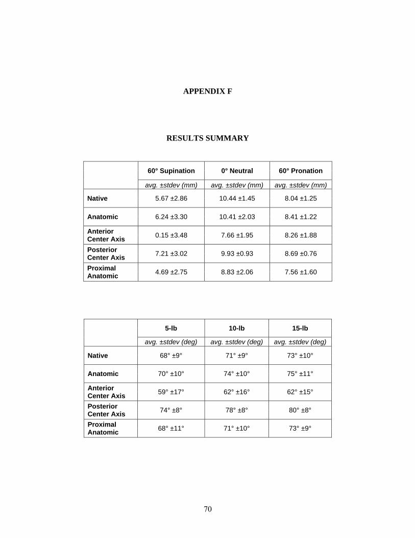
APPENDIX F
RESULTS SUMMARY
60° Supination 0° Neutral 60° Pronation
avg. ±stdev (mm) avg. ±stdev (mm) avg. ±stdev (mm)
Native 5.67 ±2.86 10.44 ±1.45 8.04 ±1.25
Anatomic 6.24 ±3.30 10.41 ±2.03 8.41 ±1.22
Anterior Center Axis 0.15 ±3.48 7.66 ±1.95 8.26 ±1.88
Posterior Center Axis 7.21 ±3.02 9.93 ±0.93 8.69 ±0.76
Proximal Anatomic 4.69 ±2.75 8.83 ±2.06 7.56 ±1.60
5-lb 10-lb 15-lb
avg. ±stdev (deg) avg. ±stdev (deg) avg. ±stdev (deg)
Native 68° ±9° 71° ±9° 73° ±10°
Anatomic 70° ±10° 74° ±10° 75° ±11°
Anterior Center Axis 59° ±17° 62° ±16° 62° ±15°
Posterior Center Axis 74° ±8° 78° ±8° 80° ±8°
Proximal Anatomic 68° ±11° 71° ±10° 73° ±9°
70

BIBLIOGRAPHY
1. Chillemi, C., M. Marinelli, and V. De Cupis, Rupture of the distal biceps brachii tendon: conservative treatment versus anatomic reinsertion--clinical and radiological evaluation after 2 years. Arch Orthop Trauma Surg, 2007. 127(8): p. 705-8.
2. Hetsroni, I., et al., Avulsion of the distal biceps brachii tendon in middle-aged population: is surgical repair advisable? A comparative study of 22 patients treated with either nonoperative management or early anatomical repair. Injury, 2008. 39(7): p. 753-60.
3. Baker, B.E. and D. Bierwagen, Rupture of the distal tendon of the biceps brachii. Operative versus non-operative treatment. J Bone Joint Surg Am, 1985. 67(3): p. 414-7.
4. Norman, W. 1999.
5. Mrabet, Y. 2008.
6. Neumann, D.A., Kinesiology of the Musculoskeletal System. 1st ed. 2002, St. Louis: Mosby Inc.
7. Biodex Medical Systems, I., Biodex Multi Joint-System Pro: Setup and Operation Manual. 2006, Shirley, New York.
8. The Color Atlas of Human Anatomy, ed. V. Vannini and G. Pogliani, New York: Harmony Books.
9. Forthman, C.L., et al., Cross-sectional anatomy of the bicipital tuberosity and biceps brachii tendon insertion: relevance to anatomic tendon repair. J Shoulder Elbow Surg, 2008. 17(3): p. 522-6.
10. Safran, M.R. and S.M. Graham, Distal biceps tendon ruptures: incidence, demographics, and the effect of smoking. Clin Orthop Relat Res, 2002(404): p. 275-83.
11. Leighton, M.M., C.A. Bush-Joseph, and B.R. Bach, Jr., Distal biceps brachii repair. Results in dominant and nondominant extremities. Clin Orthop Relat Res, 1995(317): p. 114-21.
12. Morrey, B.F., et al., Rupture of the distal tendon of the biceps brachii. A biomechanical study. J Bone Joint Surg Am, 1985. 67(3): p. 418-21.
13. eORTHOPOD. 2003.
14. O'Driscoll, S.W., L.B. Goncalves, and P. Dietz, The hook test for distal biceps tendon avulsion. Am J Sports Med, 2007. 35(11): p. 1865-9.
71
15. Seiler III, J.G., et al., The Distal Biceps Tendon - Two potential mechanisms involved in its rupture: Arterial supply and mechanical impingement. J Shoulder Elbow Surg, 1995. 4: p. 149-56.
16. Dobbie, R.P., Avulsion of the Lower Biceps Brachii Tendon, Analysis of Fifty-one Previously Unreported Cases. Am. J. Surg., 1941. 51: p. 662-683.
17. Meherin, J.M. and E.S.K. Jr., The Treatment of Ruptures of the Distal Biceps Brachii Tendon. Am. J. Surg., 1960. 99: p. 636-640.
18. Boyd, J.B. and L.D. Anderson, A Method for the Reinsertion of the Distal Biceps Tendon. J Bone Joint Surg Am, 1961. 43: p. 1041-1043.
19. Le Huec, J.C., et al., Distal rupture of the tendon of biceps brachii. Evaluation by MRI and the results of repair. J Bone Joint Surg Br, 1996. 78(5): p. 767-70.
20. Klonz, A., et al., Rupture of the distal biceps brachii tendon: isokinetic power analysis and complications after anatomic reinsertion compared with fixation to the brachialis muscle. J Shoulder Elbow Surg, 2003. 12(6): p. 607-11.
21. Agins, H.J., et al., Rupture of the distal insertion of the biceps brachii tendon. Clin Orthop Relat Res, 1988(234): p. 34-8.
22. Failla, J.M., et al., Proximal radioulnar synostosis after repair of distal biceps brachii rupture by the two-incision technique. Report of four cases. Clin Orthop Relat Res, 1990(253): p. 133-6.
23. Davison, B.L., W.D. Engber, and L.J. Tigert, Long term evaluation of repaired distal biceps brachii tendon ruptures. Clin Orthop Relat Res, 1996(333): p. 186-91.
24. Karunakar, M.A., P. Cha, and P.J. Stern, Distal biceps ruptures. A followup of Boyd and Anderson repair. Clin Orthop Relat Res, 1999(363): p. 100-7.
25. Kelly, E.W., B.F. Morrey, and S.W. O'Driscoll, Complications of repair of the distal biceps tendon with the modified two-incision technique. J Bone Joint Surg Am, 2000. 82-A(11): p. 1575-81.
26. Bisson, L., et al., Complications associated with repair of a distal biceps rupture using the modified two-incision technique. J Shoulder Elbow Surg, 2008. 17(1 Suppl): p. 67S-71S.
27. Barnes, S.J., S.G. Coleman, and D. Gilpin, Repair of avulsed insertion of biceps. A new technique in four cases. J Bone Joint Surg Br, 1993. 75(6): p. 938-9.
28. Balabaud, L., et al., Repair of distal biceps tendon ruptures using a suture anchor and an anterior approach. J Hand Surg [Br], 2004. 29(2): p. 178-82.
29. Khan, A.D., et al., Repair of distal biceps tendon ruptures using suture anchors through a single anterior incision. Arthroscopy, 2008. 24(1): p. 39-45.
72

30. Strauch, R.J. and M.P. Rosenwasser, Single incision repair of distal biceps tendon rupture. Tech Hand Up Extrem Surg, 1998. 2(4): p. 253-61.
31. Lynch, S.A., D.M. Beard, and P.A. Renstrom, Repair of distal biceps tendon rupture with suture anchors. Knee Surg Sports Traumatol Arthrosc, 1999. 7(2): p. 125-31.
32. Pinto, M.C., D.S. Louis, and L.J. PJ, Distal biceps tendon repair: a single incision technique. Tech Hand Up Extrem Surg, 2000. 4(1): p. 30-3.
33. Bain, G.I., et al., Repair of distal biceps tendon rupture: a new technique using the Endobutton. J Shoulder Elbow Surg, 2000. 9(2): p. 120-6.
34. Greenberg, J.A., et al., EndoButton-assisted repair of distal biceps tendon ruptures. J Shoulder Elbow Surg, 2003. 12(5): p. 484-90.
35. Hallam, P. and G.I. Bain, Repair of chronic distal biceps tendon ruptures using autologous hamstring graft and the Endobutton. J Shoulder Elbow Surg, 2004. 13(6): p. 648-51.
36. Sharma, S. and G. MacKay, Endoscopic repair of distal biceps tendon using an EndoButton. Arthroscopy, 2005. 21(7): p. 897.
37. Ranelle, R.G., Use of the Endobutton in repair of the distal biceps brachii tendon. Proc (Bayl Univ Med Cent), 2007. 20(3): p. 235-6.
38. Pereira, D.S., et al., Surgical repair of distal biceps tendon ruptures: a biomechanical comparison of two techniques. Am J Sports Med, 2002. 30(3): p. 432-6.
39. Lemos, S.E., E. Ebramzedeh, and R.S. Kvitne, A new technique: in vitro suture anchor fixation has superior yield strength to bone tunnel fixation for distal biceps tendon repair. Am J Sports Med, 2004. 32(2): p. 406-10.
40. Idler, C.S., et al., Distal biceps tendon repair: a biomechanical comparison of intact tendon and 2 repair techniques. Am J Sports Med, 2006. 34(6): p. 968-74.
41. Spang, J.T., P.S. Weinhold, and S.G. Karas, A biomechanical comparison of EndoButton versus suture anchor repair of distal biceps tendon injuries. J Shoulder Elbow Surg, 2006. 15(4): p. 509-14.
42. Kettler, M., et al., Failure strengths in distal biceps tendon repair. Am J Sports Med, 2007. 35(9): p. 1544-8.
43. Mazzocca, A.D., et al., Biomechanical evaluation of 4 techniques of distal biceps brachii tendon repair. Am J Sports Med, 2007. 35(2): p. 252-8.
44. Kettler, M., et al., Reattachment of the distal tendon of biceps: factors affecting the failure strength of the repair. J Bone Joint Surg Br, 2008. 90(1): p. 103-6.
73

45. Murray, W.M., S.L. Delp, and T.S. Buchanan, Variation of muscle moment arms with elbow and forearm position. J Biomech, 1995. 28(5): p. 513-25.
46. Haugstvedt, J.R., R.A. Berger, and L.J. Berglund, A mechanical study of the moment-forces of the supinators and pronators of the forearm. Acta Orthop Scand, 2001. 72(6): p. 629-34.
47. Henry, J., et al., Biomechanical analysis of distal biceps tendon repair methods. Am J Sports Med, 2007. 35(11): p. 1950-4.
48. Giuffre, B.M. and M.J. Moss, Optimal positioning for MRI of the distal biceps brachii tendon: flexed abducted supinated view. AJR Am J Roentgenol, 2004. 182(4): p. 944-6.
49. Kaeding, C., R. Fischer, and T. Anderson, Modified distal biceps tendon repair. J Orthop Tech, 1996. 4: p. 29-32.
50. Gallagher, M.A., et al., Effects of age, testing speed, and arm dominance on isokinetic strength of the elbow. J Shoulder Elbow Surg, 1997. 6(4): p. 340-6.
51. D'Arco, P., et al., Clinical, functional, and radiographic assessments of the conventional and modified Boyd-Anderson surgical procedures for repair of distal biceps tendon ruptures. Am J Sports Med, 1998. 26(2): p. 254-61.
52. Moosmayer, S., A. Odinsson, and I. Holm, Distal biceps tendon rupture operated on with the Boyd-Anderson technique: follow-up of 9 patients with isokinetic examination after 1 year. Acta Orthop Scand, 2000. 71(4): p. 399-402.
53. Wiley, W.B., et al., Late reconstruction of chronic distal biceps tendon ruptures with a semitendinosus autograft technique. J Shoulder Elbow Surg, 2006. 15(4): p. 440-4.
54. Weinstein, D.M., et al., Elbow function after repair of the distal biceps brachii tendon with a two-incision approach. J Shoulder Elbow Surg, 2008. 17(1 Suppl): p. 82S-86S.
55. De Carli, A., et al., Surgical repair of the distal biceps brachii tendon: clinical and isokinetic long-term follow-up. Knee Surg Sports Traumatol Arthrosc, 2009. 17(7): p. 850-6.
56. Nesterenko, S., et al., Elbow strength and endurance in patients with a ruptured distal biceps tendon. J Shoulder Elbow Surg, 2009.
57. Peeters, T., et al., Functional outcome after repair of distal biceps tendon ruptures using the endobutton technique. J Shoulder Elbow Surg, 2009. 18(2): p. 283-7.
58. Cheung, E.V., M. Lazarus, and M. Taranta, Immediate range of motion after distal biceps tendon repair. J Shoulder Elbow Surg, 2005. 14(5): p. 516-8.
59. McKee, M.D., et al., Patient-oriented functional outcome after repair of distal biceps tendon ruptures using a single-incision technique. J Shoulder Elbow Surg, 2005. 14(3): p. 302-6.
74

75
60. Darlis, N.A. and D.G. Sotereanos, Distal biceps tendon reconstruction in chronic ruptures. J Shoulder Elbow Surg, 2006. 15(5): p. 614-9.
61. Freeman, C.R., et al., Nonoperative treatment of distal biceps tendon ruptures compared with a historical control group. J Bone Joint Surg Am, 2009. 91(10): p. 2329-34.