effect of overhang deck construction on plate girder …
TRANSCRIPT
International Journal of Bridge Engineering (IJBE), Vol. 5, No. 2, (2017), pp. 21-33
EFFECT OF OVERHANG DECK CONSTRUCTION ON
PLATE GIRDER BRIDGES
Md Ashiquzzaman1, Bora Bozkurt
2, Li Hui
3, Ahmed Ibrahim
4,
Will Lindquist5, Riyadh Hindi
6
1,2,3,6 Saint Louis University, Dept. of Civil Engineering, Saint Louis, MO, USA 4 University of Idaho, Dept. of Civil Engineering, Moscow, ID, USA
5 William Jewell College, Liberty, Missouri, USA, e-mail: [email protected], [email protected], [email protected], [email protected],
[email protected], [email protected]
ABSTRACT: In order to construct a wider bridge deck, it is usual to extend the
bridge deck past the exterior girders. Construction of these overhangs may result in a number of issues for both steel and concrete girder bridges. Bridge
contractors prefer to place the bridge screed and finishing machine on the
overhang during concrete placement in order to make placement and finishing operations easier. This construction methodology could be dangerous resulting
in excessive exterior girder rotation leading to a loss in deck thickness and over
stress in the girders. Excessive overhang loads on the girders may cause local
instabilities, global buckling, or both. In this research, the effect of overhang construction loads on the rotation of exterior plate girders during deck
construction was studied. Two plate girder bridges were monitored in the field
during construction in the state of Illinois and the rotation values were replicated using finite element analysis. The rotation results obtained from the
field and finite element analysis of plate girder bridges showed small exterior
girder rotation during bridge deck construction. These results could be used to
justify relaxed bracing requirements for exterior girders during construction.
KEYWORDS: Plate girder bridge; Exterior girder rotation; Screed machine;
overhang deck; Tie bars; Construction loads.
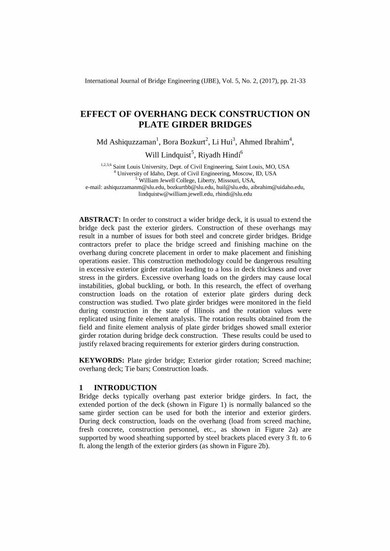
1 INTRODUCTION Bridge decks typically overhang past exterior bridge girders. In fact, the
extended portion of the deck (shown in Figure 1) is normally balanced so the same girder section can be used for both the interior and exterior girders.
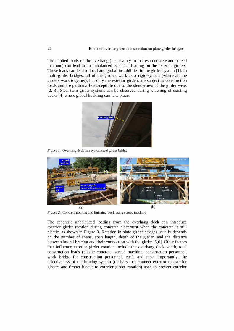
During deck construction, loads on the overhang (load from screed machine,
fresh concrete, construction personnel, etc., as shown in Figure 2a) are
supported by wood sheathing supported by steel brackets placed every 3 ft. to 6 ft. along the length of the exterior girders (as shown in Figure 2b).
22 Effect of overhang deck construction on plate girder bridges
The applied loads on the overhang (i.e., mainly from fresh concrete and screed
machine) can lead to an unbalanced eccentric loading on the exterior girders.
These loads can lead to local and global instabilities in the girder-system [1]. In multi-girder bridges, all of the girders work as a rigid-system (where all the
girders work together), but only the exterior girders are subject to construction
loads and are particularly susceptible due to the slenderness of the girder webs [2, 3]. Steel twin girder systems can be observed during widening of existing
decks [4] where global buckling can take place.
Figure 1. Overhang deck in a typical steel girder bridge
(a)
(b)
Figure 2. Concrete pouring and finishing work using screed machine
The eccentric unbalanced loading from the overhang deck can introduce exterior girder rotation during concrete placement when the concrete is still
plastic, as shown in Figure 3. Rotation in plate girder bridges usually depends
on the number of spans, span length, depth of the girder, and the distance between lateral bracing and their connection with the girder [5,6]. Other factors
that influence exterior girder rotation include the overhang deck width, total
construction loads (plastic concrete, screed machine, construction personnel,
work bridge for construction personnel, etc.), and most importantly, the effectiveness of the bracing system (tie bars that connect exterior to exterior
girders and timber blocks to exterior girder rotation) used to prevent exterior
Ashiquzzaman et al. 23
girder rotation during construction. It is possible to reduce the net rotation
caused by these loads by applying an appropriate permanent or temporary
bracing system to the girders.
(a)
(b)
Figure 3. Exterior girder rotation due to unbalanced eccentric load on overhang deck
A commonly used bracing system in the state of Illinois includes transverse tie
bars and wooden struts. The transverse tie arrangement (shown in Figure 4) includes a No. 4 steel reinforcing bar connected from one exterior girder to the
opposite exterior girder. These rotation prevention tie bars are typically placed
at a 3 ft. to 4 ft. spacing along the length of the bridge. Effectiveness in
tightening the ties plays a significant role in their effectiveness. Square timber blocks (4 in. × 4 in.) are used as struts in between the exterior and first interior
girder to prevent rotation as shown in Figure 4.
In this paper, two plate girder bridges (one skewed and one non-skewed) were monitored during construction to measure the exterior girder rotation due
to the overhang loads. A detailed finite element analysis was performed and
validated using the field data.
Figure 4. Temporary bracing system to prevent exterior girder rotation

24 Effect of overhang deck construction on plate girder bridges
2 BRIDGE DESCRIPTION AND INSTRUMENTATION
2.1 Description of the bridges For this study, a skewed and non-skewed plate girder bridge were selected for
field instrumentation. General information for these bridges is presented in
Table 1.
Table 1. Fundamental information of the bridges
Bridge A Bridge B
Beam type 78-in. steel plate girder 64-in. steel plate girder
Skewed? Non-skewed 30º
Number of span 4 2
Span length 200 ft. 145 ft.
Concrete poured Up to 149 ft.- 8.5 in. Up to 78 ft.
Overhang width 3 ft.-4 in. 3 ft.-5 in.
Girder spacing 6 ft.-6 in. 9 ft. -1 in.
Tie type Transverse tie Transverse tie
Screed location On overhang deck On overhang deck
2.2 Dual-axis tilt sensor Dual-axis (transverse and longitudinal direction) tilt sensors were used to
monitor girder rotations. Tilt sensor locations are shown in Figure 5. The tilt sensors are capable of measuring ±20º rotation. Extra care was taken during
installation to ensure the tilt sensors were installed perpendicular to the girder
web and flange. All rotations were measured in degrees.
(a)
(b)
Figure 5. Installed tilt sensor in the bridge: (a) tilt sensor, (b) locations of tilt sensors
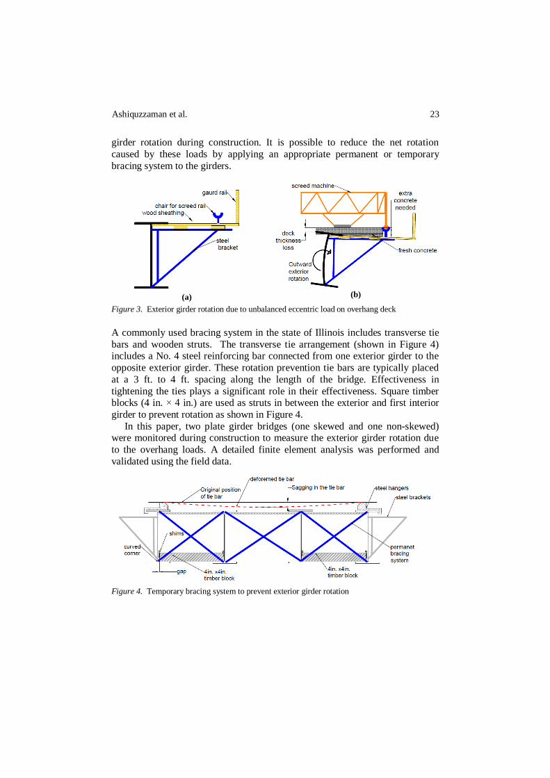
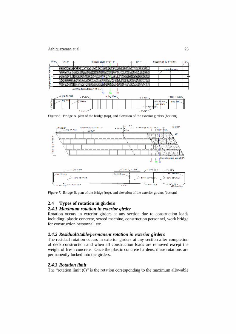
2.3 Sections for the instrumentation The sections used for instrumentation are shown in Figure 6 and Figure 7 for the non-skewed and skewed bridge, respectively.
Ashiquzzaman et al. 25
Figure 6. Bridge A. plan of the bridge (top), and elevation of the exterior girders (bottom)
Figure 7. Bridge B. plan of the bridge (top), and elevation of the exterior girders (bottom)
2.4 Types of rotation in girders
2.4.1 Maximum rotation in exterior girder Rotation occurs in exterior girders at any section due to construction loads
including: plastic concrete, screed machine, construction personnel, work bridge
for construction personnel, etc.
2.4.2 Residual/stable/permanent rotation in exterior girders The residual rotation occurs in exterior girders at any section after completion of deck construction and when all construction loads are removed except the
weight of fresh concrete. Once the plastic concrete hardens, these rotations are
permanently locked into the girders.
2.4.3 Rotation limit The “rotation limit (θ)” is the rotation corresponding to the maximum allowable
26 Effect of overhang deck construction on plate girder bridges
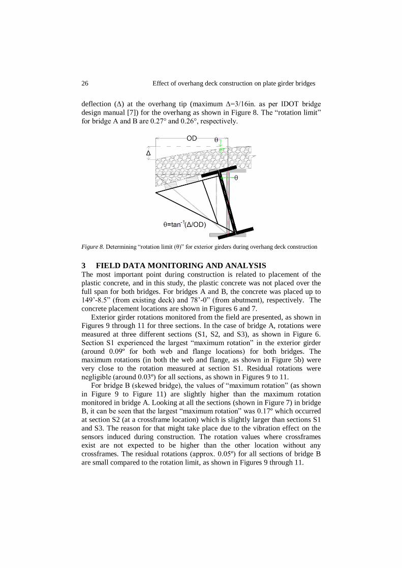
deflection (Δ) at the overhang tip (maximum Δ=3/16in. as per IDOT bridge
design manual [7]) for the overhang as shown in Figure 8. The “rotation limit”
for bridge A and B are 0.27° and 0.26°, respectively.
Figure 8. Determining “rotation limit (θ)” for exterior girders during overhang deck construction
3 FIELD DATA MONITORING AND ANALYSIS The most important point during construction is related to placement of the
plastic concrete, and in this study, the plastic concrete was not placed over the
full span for both bridges. For bridges A and B, the concrete was placed up to 149’-8.5” (from existing deck) and 78’-0” (from abutment), respectively. The
concrete placement locations are shown in Figures 6 and 7.
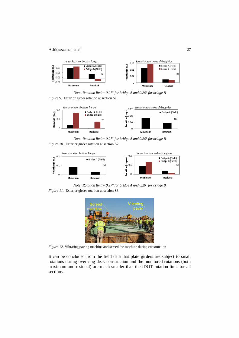
Exterior girder rotations monitored from the field are presented, as shown in Figures 9 through 11 for three sections. In the case of bridge A, rotations were
measured at three different sections (S1, S2, and S3), as shown in Figure 6.
Section S1 experienced the largest “maximum rotation” in the exterior girder
(around 0.09º for both web and flange locations) for both bridges. The maximum rotations (in both the web and flange, as shown in Figure 5b) were
very close to the rotation measured at section S1. Residual rotations were
negligible (around 0.03º) for all sections, as shown in Figures 9 to 11. For bridge B (skewed bridge), the values of “maximum rotation” (as shown
in Figure 9 to Figure 11) are slightly higher than the maximum rotation
monitored in bridge A. Looking at all the sections (shown in Figure 7) in bridge B, it can be seen that the largest “maximum rotation” was 0.17º which occurred
at section S2 (at a crossframe location) which is slightly larger than sections S1
and S3. The reason for that might take place due to the vibration effect on the
sensors induced during construction. The rotation values where crossframes exist are not expected to be higher than the other location without any
crossframes. The residual rotations (approx. 0.05º) for all sections of bridge B
are small compared to the rotation limit, as shown in Figures 9 through 11.
Ashiquzzaman et al. 27
Note: Rotation limit= 0.27° for bridge A and 0.26° for bridge B
Figure 9. Exterior girder rotation at section S1
Note: Rotation limit= 0.27° for bridge A and 0.26° for bridge B
Figure 10. Exterior girder rotation at section S2
Note: Rotation limit= 0.27° for bridge A and 0.26° for bridge B
Figure 11. Exterior girder rotation at section S3
Figure 12. Vibrating paving machine and screed the machine during construction
It can be concluded from the field data that plate girders are subject to small
rotations during overhang deck construction and the monitored rotations (both maximum and residual) are much smaller than the IDOT rotation limit for all
sections.

28 Effect of overhang deck construction on plate girder bridges
4 FINITE ELEMENT ANALYSIS A validated finite element model is developed in order to conduct parametric studies to identify other factors that influence exterior girder rotation during
bridge deck construction. The comprehensive finite element code ABAQUS
was used to conduct bridge simulations. The following sections present the
material properties and the details of the elements used in this study.
4.1 Material modeling The material properties for the steel, timber blocks, and concrete which was
used for modeling can be found in Table 2 [8].
Table 2. Material properties of steel Materials Properties Values
Steel Modulus of elasticity E = 29000 ksi
Poisson’s ratio in elastic stage ν = 0.3
Timber Modulus of elasticity E = 1300 ksi Poisson’s ratio in elastic stage ν = 0.37
Concrete Unit weight (145 lb/ft3) 0.087 pci
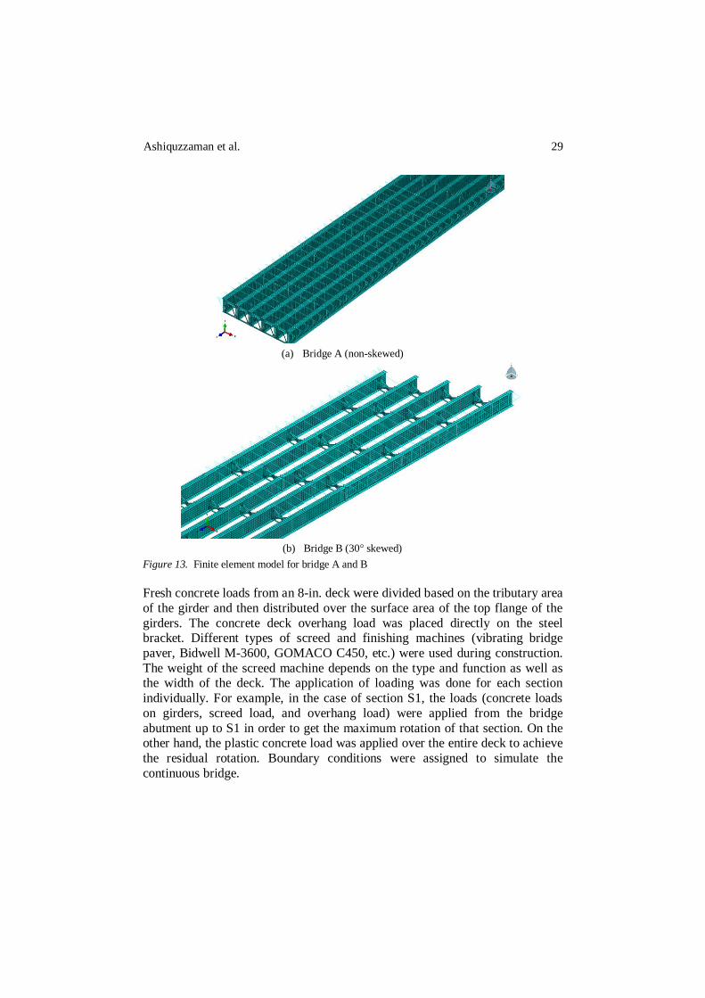
4.2 Finite element modeling Full-scale FE models of bridges A and B are shown in Figure 13 and are based
on actual plan dimensions. Bridge girders and diaphragms were modeled using
shell elements, and transverse tie bars were modeled using linear truss elements. Overhang steel brackets were modeled as beam elements. Transverse tie bars
are usually affected by sagging during construction and installation, as shown in
Figure 4, due to self-weight, interference with other reinforcement, and improper tightening. This can lead to ineffectiveness of the ties and result in
more rotation. In the finite element study, a nonlinear link element (translator)
was used with an assigned “gap” (0.5 in. for bridge A and 0.1 in for bridge B) to
simulate sagging (as shown in Figure 4) of the transverse bracing bars in the field. The 4 in. × 4 in. timber blocks were assumed to be improperly shimmed
due to the fillet at the corner of the web and bottom flange, as shown in Figure
4. A truss element was used to represent the timber blocks, and in the connected nodes, a nonlinear translator link with an assigned gap (0.22 in. for bridge A
and 0.1 in. for bridge B) was used as a constraint between the timber blocks and
girders to simulate the gap. In both cases (tie bars and timber blocks), the gap value in the nonlinear translator connector was determined through trial and
error by matching field-measured rotations to calculated rotations.
Ashiquzzaman et al. 29
(a) Bridge A (non-skewed)
(b) Bridge B (30° skewed)
Figure 13. Finite element model for bridge A and B
Fresh concrete loads from an 8-in. deck were divided based on the tributary area
of the girder and then distributed over the surface area of the top flange of the
girders. The concrete deck overhang load was placed directly on the steel bracket. Different types of screed and finishing machines (vibrating bridge
paver, Bidwell M-3600, GOMACO C450, etc.) were used during construction.
The weight of the screed machine depends on the type and function as well as the width of the deck. The application of loading was done for each section
individually. For example, in the case of section S1, the loads (concrete loads
on girders, screed load, and overhang load) were applied from the bridge
abutment up to S1 in order to get the maximum rotation of that section. On the other hand, the plastic concrete load was applied over the entire deck to achieve
the residual rotation. Boundary conditions were assigned to simulate the
continuous bridge.
30 Effect of overhang deck construction on plate girder bridges
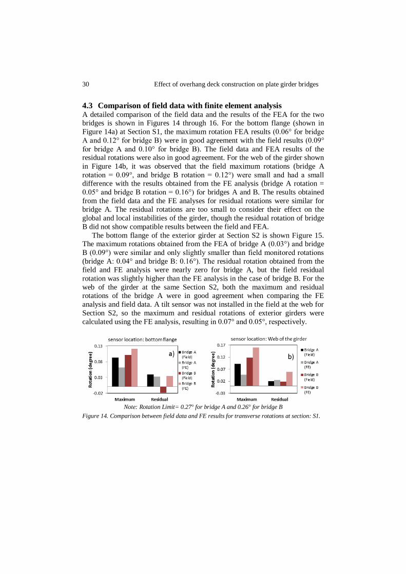
4.3 Comparison of field data with finite element analysis A detailed comparison of the field data and the results of the FEA for the two bridges is shown in Figures 14 through 16. For the bottom flange (shown in
Figure 14a) at Section S1, the maximum rotation FEA results (0.06° for bridge
A and 0.12° for bridge B) were in good agreement with the field results (0.09°
for bridge A and 0.10° for bridge B). The field data and FEA results of the residual rotations were also in good agreement. For the web of the girder shown
in Figure 14b, it was observed that the field maximum rotations (bridge A
rotation = 0.09°, and bridge B rotation = 0.12°) were small and had a small difference with the results obtained from the FE analysis (bridge A rotation =
0.05° and bridge B rotation = 0.16°) for bridges A and B. The results obtained
from the field data and the FE analyses for residual rotations were similar for bridge A. The residual rotations are too small to consider their effect on the
global and local instabilities of the girder, though the residual rotation of bridge
B did not show compatible results between the field and FEA.
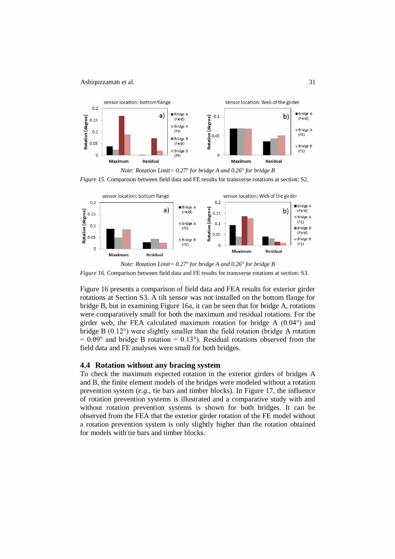
The bottom flange of the exterior girder at Section S2 is shown Figure 15. The maximum rotations obtained from the FEA of bridge A (0.03°) and bridge
B (0.09°) were similar and only slightly smaller than field monitored rotations
(bridge A: 0.04° and bridge B: 0.16°). The residual rotation obtained from the field and FE analysis were nearly zero for bridge A, but the field residual
rotation was slightly higher than the FE analysis in the case of bridge B. For the
web of the girder at the same Section S2, both the maximum and residual rotations of the bridge A were in good agreement when comparing the FE
analysis and field data. A tilt sensor was not installed in the field at the web for
Section S2, so the maximum and residual rotations of exterior girders were
calculated using the FE analysis, resulting in 0.07° and 0.05°, respectively.
Note: Rotation Limit= 0.27° for bridge A and 0.26° for bridge B
Figure 14. Comparison between field data and FE results for transverse rotations at section: S1.
Ashiquzzaman et al. 31
Note: Rotation Limit= 0.27° for bridge A and 0.26° for bridge B
Figure 15. Comparison between field data and FE results for transverse rotations at section: S2.
Note: Rotation Limit= 0.27° for bridge A and 0.26° for bridge B
Figure 16. Comparison between field data and FE results for transverse rotations at section: S3.
Figure 16 presents a comparison of field data and FEA results for exterior girder
rotations at Section S3. A tilt sensor was not installed on the bottom flange for bridge B, but in examining Figure 16a, it can be seen that for bridge A, rotations
were comparatively small for both the maximum and residual rotations. For the
girder web, the FEA calculated maximum rotation for bridge A (0.04°) and
bridge B (0.12°) were slightly smaller than the field rotation (bridge A rotation = 0.09° and bridge B rotation = 0.13°). Residual rotations observed from the
field data and FE analyses were small for both bridges.
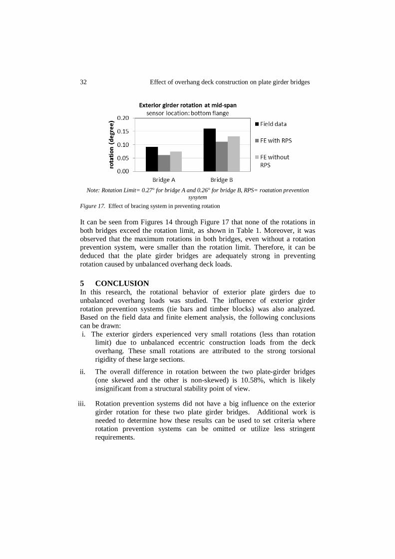
4.4 Rotation without any bracing system To check the maximum expected rotation in the exterior girders of bridges A
and B, the finite element models of the bridges were modeled without a rotation prevention system (e.g., tie bars and timber blocks). In Figure 17, the influence
of rotation prevention systems is illustrated and a comparative study with and
without rotation prevention systems is shown for both bridges. It can be observed from the FEA that the exterior girder rotation of the FE model without
a rotation prevention system is only slightly higher than the rotation obtained
for models with tie bars and timber blocks.
32 Effect of overhang deck construction on plate girder bridges
Note: Rotation Limit= 0.27° for bridge A and 0.26° for bridge B, RPS= roatation prevention
sysytem
Figure 17. Effect of bracing system in preventing rotation
It can be seen from Figures 14 through Figure 17 that none of the rotations in
both bridges exceed the rotation limit, as shown in Table 1. Moreover, it was
observed that the maximum rotations in both bridges, even without a rotation prevention system, were smaller than the rotation limit. Therefore, it can be
deduced that the plate girder bridges are adequately strong in preventing
rotation caused by unbalanced overhang deck loads.
5 CONCLUSION In this research, the rotational behavior of exterior plate girders due to
unbalanced overhang loads was studied. The influence of exterior girder
rotation prevention systems (tie bars and timber blocks) was also analyzed. Based on the field data and finite element analysis, the following conclusions
can be drawn:
i. The exterior girders experienced very small rotations (less than rotation limit) due to unbalanced eccentric construction loads from the deck
overhang. These small rotations are attributed to the strong torsional
rigidity of these large sections.
ii. The overall difference in rotation between the two plate-girder bridges
(one skewed and the other is non-skewed) is 10.58%, which is likely
insignificant from a structural stability point of view.
iii. Rotation prevention systems did not have a big influence on the exterior
girder rotation for these two plate girder bridges. Additional work is
needed to determine how these results can be used to set criteria where rotation prevention systems can be omitted or utilize less stringent
requirements.
Ashiquzzaman et al. 33
6 ACKNOWLEDGEMENT This project was made possible by funding from the Illinois Department of Transportation through the Illinois Center for Transportation. Their support
along with support provided by Saint Louis University is very much
appreciated.
REFERENCES [1] Fasl, J, “The influence of overhang construction on girder design”, Doctoral dissertation,
University of Texas at Austin, 2008. [2] Shokouhian, M, & Shi, Y, “Flexural strength of hybrid steel I-beams based on
slenderness”, Engineering Structures, Vol. 93, pp-114-128, 2015. [3] Gupta, V K, Okui, Y, & NAGAI, M, “Development of web slenderness limits for composite
I-girders accounting for initial bending moment”, Structural Engineering/Earthquake Engineering, Vol. 23, No. 2, pp-229S-239S, 2006.
[4] Yura, J, Helwig, T, Herman, R, & Zhou, C, “Global lateral buckling of I-shaped girder systems”, Journal of structural engineering, Vol. 134, No. 9, pp-1487-1494, 2008.
[5] Schilling, C G, “Moment-rotation tests of steel bridge girders” Journal of Structural Engineering, Vol. 114, No. 1, pp-134-149, 1988.
[6] Helwig, T, & Yura, J, “Steel Bridge Design Handbook: Bracing System Design” Rep. No. FHWA-IF-12-052-Vol. 13, 2012.
[7] Illinois Department of Transportation (IDOT). IDOT LRFD Bridge Design Manual. 2012, Springfield, IL: IDOT.
[8] CEN, “Eurocode SS-EN 1993-1-1, s.l.: European Committee for Standardization”, Swedish Standards Institute, 1995.