effective: december 1999 type hcb-1...type hcb-1 pilot wire relay system 41-971.3m 5 the pilot-wire...
TRANSCRIPT
ABB Automation Inc.Substation Automation and Protection DivisionCoral Springs, FL 33065
Instruction Leaflet
All possible contingencies which may arise during installation, operation or maintenvariations of this equipment do not purport to be covered by these instructions. If furthby purchaser regarding this particular installation, operation or maintenance of this ePower T&D Company Inc. representative should be contacted.
Effective: December 1999
( | ) Denotes Change Since Previous Issue
Printed in U.S.A.
ABBABBABBABB
R
41-971.3M
Type HCB-1Pilot-wire Relay System
Supersedes I.L. 41-971.3L, Dated August 1996
! CAUTION
Before putting protective relays into service,
remove all blocking which may have been
inserted for the purpose of securing the parts
during shipment, make sure that all moving
parts operate freely, inspect the contacts to
see that they are clean and close properly, and
operate the relay to check the settings and
electrical connections.
1.0 APPLICATION
The type HCB-1 relay is a high speed pilot-wire relaydesigned for the complete phase and ground protec-tion of two and three terminal transmission lines.Simultaneous tripping of the relay at each terminal isobtained in about 20 milliseconds for all faults. Acomplete installation for a two terminal line consistsof two relays, two insulating transformers, and aninterconnecting pilot-wire circuit. For a three terminalline, three relays, three insulating transformers, and awye-connected pilot-wire circuit with branches ofequal series resistance are required.
The HCB-1 and HCB relays are not compatible, sincethe filter response is not the same.
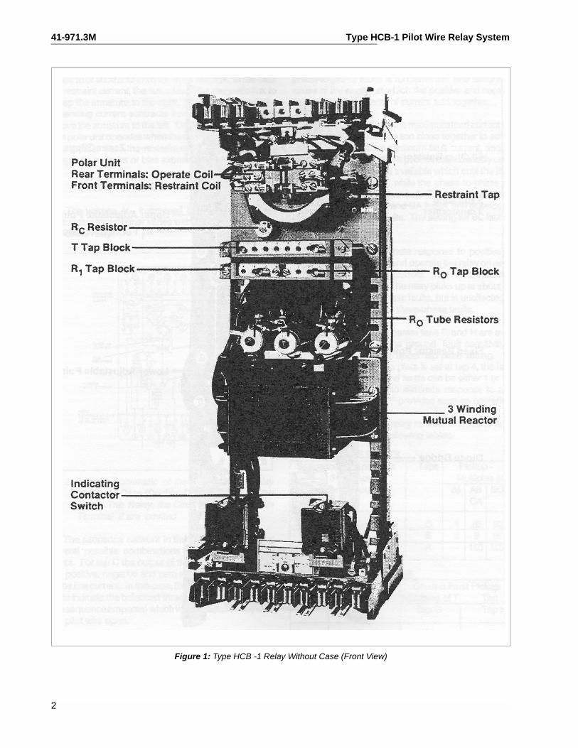
2.0 CONSTRUCTION
The relay consists of a combination positive, nega-tive, and zero phase sequence filter, a saturating aux-
iliary transformer, two full wave rectifier units, a polarunit, a Zener clipper, and an indicating contactorswitch (ICS), all mounted in a single case. The exter-nal equipment normally supplied with the relay con-sists of an insulating transformer, a millimeter andtest switch.
2.1. SEQUENCE FILTER
The sequence filter consists of a three-legged ironcore reactor and a set of resistors designated R1 andR0. The reactor has three windings; two primary anda tapped secondary winding, wound on the center legof a “F” type of lamination. The secondary taps arewired to the A, B and C tap connections in front of therelay. R0 consists of three tube resistors with tapswired to the F, G and H tap connections in the front ofthe relay.
2.2. SATURATING TRANSFORMER
The output of the sequence filter connects to the pri-mary of a two-winding saturating transformer. The pri-mary winding is tapped and wired to a tap block T inthe front of the relay. The secondary winding is con-nected to the Zener clipper circuit and from a fixedtap to the relay coil circuits.
2.3. POLAR UNIT
This unit consists of a rectangular-shape magneticframe, an electromagnet, a permanent magnet, andan armature with either one or two contacts. Thepoles of the crescent-shaped permanent magnetbridge the magnetic frame. The magnetic frame con-sists of three pieces joined in the rear with two brassrods and silver solder. These non-magnetic joints
ance, and all details ander information is desiredquipment, the local ABB
41-971.3M Type HCB-1 Pilot Wire Relay System
Figure 1: Type HCB -1 Relay Without Case (Front View)
2
Type HCB-1 Pilot Wire Relay System 41-971.3M
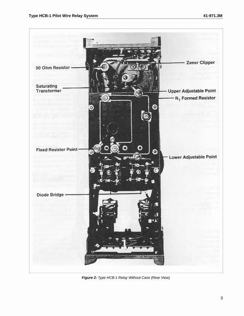
Figure 2: Type HCB-1 Relay Without Case (Rear View)
3
41-971.3M Type HCB-1 Pilot Wire Relay System
represent air gaps which are bridged by two adjust-able magnetic shunts. The operating and restraintwindings are concentrically wound around a mag-netic core. The armature is fastened to this core atone end and floats in the front air gap at the otherend. The moving contact is connected to the free endof a leaf spring.
2.4. Restraint Taps
A set of restraint taps are located on the front of therelay near the polar unit. These taps are the maxi-mum and minimum restraint taps of the relay.
2.5. INDICATING CONTACTOR SWITCH UNIT (ICS)
The dc indicating contactor switch is a small clapper-type device. A magnetic armature, to which leaf-spring mounted contacts are attached, is attracted tothe magnetic core upon energization of the switch.When the switch closes, the moving contacts bridgetwo stationary contacts, bypassing the main relaycontacts. Also during this operation, two fingers onthe armature deflect a spring located on the front ofthe switch, which allows the operation indicator tar-get to drop. The target is reset from the outside of thecase by a push-rod located on the bottom of thecover.
The front spring, in addition to holding the target, pro-vides restraint for the armature, and thus controls thepickup value of the switch.
3.0 OPERATION
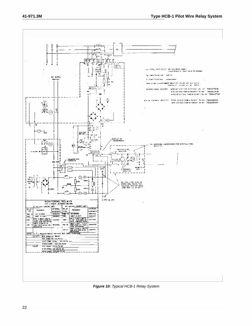
The connection of the HCB-1 system of relays to theprotected transmission line is shown in Figure 10. Insuch a connection, the relays operate for faults withinthe line terminals but not for faults external to the pro-tected transmission line. This is accomplished bycomparing the relative polarities of voltages at oppo-site ends of the transmission line by means of ametallic pilot-wire.
As shown in Figure 4, the composite sequence filterof each HCB-1 relay receives three-phase currentfrom the current transformers of the transmissionline. The composite sequence filter of the HCB-1converts the three-phase current input into a single-
phase voltage output, VF, of a magnitude which is afunction of the positive, negative and zero sequencecomponents of fault current. This voltage VF, isimpressed on the primary wiring of the saturatingtransformer. The saturating transformer output volt-age, VS, is impressed on the primary wiring of thesaturating transformer. The saturating transformeroutput voltage, VS, is impressed on the primary wir-ing of the saturating transformer. The saturatingtransformer output voltage, VS, is applied to the relaycoils and to the pilot-wire through an insulating trans-former. The saturating transformer and a zener clip-per across its secondary winding serve to limit theenergy input to the pilot-wire.
During an external fault, assuming matched relays,the magnitude of VS at both stations will be thesame. The relative polarities of the VS voltages willbe shown in Figure 4. Since the voltages add, mostof the current will circulate through the restraint coilsand the pilot-wire, with a minimum of operating coilcurrent. The relative effects of the operating andrestraint coil currents are such that the relay isrestrained.
During an internal fault, the relative VS voltagesreverse. Since the VS voltages now oppose eachother, most of the current flowing in the restraint coilsis also forced through the operating coils with a mini-mum of current in the pilot-wire. This increase inoperating current overcomes the restraining effectand both the relays operate.
Within limits, as defined in Figure 7 and under “Char-acteristics,” all the relays will operate for an internalfault regardless of the fault current distribution at thevarious stations. The nominal pickup (total internalfault current) of the relaying system is equal to theminimum trip of a single relay multiplied by the num-ber of relays. For example, if the pickup of eachrelay, with the pilot-wire open, is 6 amperes, a twoterminal line system has a nominal pickup of 2 X 6 =12 amperes.
3.1. PILOT-WIRE EFFECTS
In Figure 4 it can be seen that a short-circuited pilot-wire will short circuit the relay operating coils.Depending on the location of the short, at least oneof the relays will fail to trip during an internal fault. If
4
Type HCB-1 Pilot Wire Relay System 41-971.3M
the pilot-wire is open circuited, almost all the restraintcoil current will flow through the operating coil, andthe relay operates as an overcurrent relay on faultcurrents.
Excessive pilot-wire series impedance will approachan open-circuited condition and the relays will oper-ate during external faults. Excessive pilot-wire shuntcapacitance will approach a short-circuited conditionand the relays will not operate. The pilot-wire require-ments are given in Table 4.
3.2. POLAR UNIT THEORY
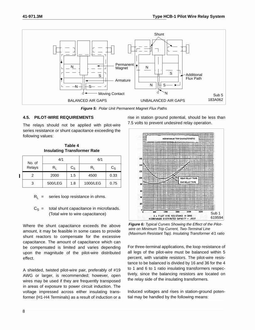
The polar unit flux paths are shown in Figure 5. Withbalanced air gaps, the permanent magnet producesflux flowing in two path, one through the front gapsand one through the rear gaps. This flux producesnorth and south poles, as shown. By turning the leftshunt in, some of the flux is forced through the arma-ture, making it a north pole. Thus, reducing the left-hand rear gap will produce a force tending to pull thearmature to the right. Similarly, reducing the right-hand gap will produce a force tending to pull thearmature to the left.
Electrical flux produced by current flowing in theoperating and restraint windings of the polar uniteither adds to or subtracts from the magnetic flux. Inthe case of restraint current, the flux adds to themagnetic flux to keep the armature to the right. Onthe other hand, the operating current subtracts fromthe magnetic flux to move the armature to the left. Onan ampere turn basis, the polar unit operates whenthe operating ampere turns are greater than therestraint ampere turns plus the magnetic restraint orbias expressed in ampere turns.
4.0 CHARACTERISTICS
The voltage, VF, impressed by the filter upon the sat-urating transformer varies with the tap setting (A, B,C) of the relay.
The sequence network in the relay is arranged forseveral possible combinations of sequence compo-nents. For tap C the output of the network will containthe positive, negative and zero sequence compo-nents of the line current. In this case, the taps on the
upper tap plate indicate the balanced three-phaseamperes (positive sequence amperes) which will pickup the relay with the pilot-wire open.
For phase-to-phase faults AB and CA, enough nega-tive sequence current has been introduced to allowthe relay to pick up at 86% of the tap setting. For BCfaults, the relay will pick up at approximately 53% ofthe tap setting. This difference in pickup current fordifferent phase-to-phase faults is fundamental; andoccurs because of the angles at which the positiveand negative sequence components of current addtogether.
In some applications, the maximum load current andminimum fault current are too close together to setthe relay to pick up under minimum fault current, andnot operate under load with the pilot-wire accidentlyopen. For these cases, tap B is available which cutsthe three-phase sensitivity in half, while the phase-to-phase setting is substantially unchanged. The relaythen trips at 90% of tap value for AB and CA faults,and at twice tap value for three-phase faults. The set-ting for BC faults is 65 percent of tap value.
It is possible to eliminate response to positive
Sub 5763A628
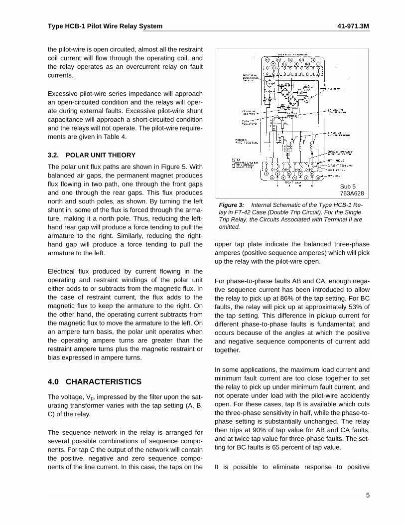
Figure 3: Internal Schematic of the Type HCB-1 Re-lay in FT-42 Case (Double Trip Circuit). For the Single Trip Relay, the Circuits Associated with Terminal II are omitted.
5
41-971.3M Type HCB-1 Pilot Wire Relay System
sequence current entirely, and operate the relay onnegative-plus-zero sequence current. Tap A is avail-able to operate in this manner. The relay picks up atabout tap value for all phase-to-phase faults, but isunaffected by balanced load current or three-phasefaults.
For ground faults, separate taps G and H are avail-able for adjustment of the ground fault sensitivity toabout 1/4 or 1/8 of the upper tap plate setting. Forexample, if the upper tap plate is set at tap 4, therelay pick-up current for ground faults can be either 1or 1/2 ampere. It is possible to eliminate response tozero sequence current. Tap F provides such an oper-ation.
The response of the relay to various types of faultsare summarized in the following tables.
The voltage, VF, impressed by the filter upon the sat-urating transformer is:
Equ. (1)
Table 3 shows the values of the C-constants in Eq. (1).
For tap settings of C and H, the voltage, VF,impressed by the filter upon the saturating trans-former is:
Equ. (2)
4.1. SINGLE RELAY PICKUP (Pilot-wire Open) IS
Single relay pickup, IS, is defined as the phase cur-rent required to operate one relay with the pilot-wireside of the insulating transformer open circuited (H1-H4). The single relay pickup point in terms of filtervoltage is:
Equ. (3)
where T is the saturating transformer tap value. Sin-gle relay pickup is defined by equating (2) and (3):
Equ. (4)
Current IS varies with the type of fault. For example,for a 3 phase fault, IS = IA1, since only positivesequence current is present. Substituting IS = IA1 inEqu. (4) and rearranging, the 3 phase fault pickup is:
Equ. (5)
For 4 Tap:
For a phase A to ground fault, if IA1 = IA2 = IA0
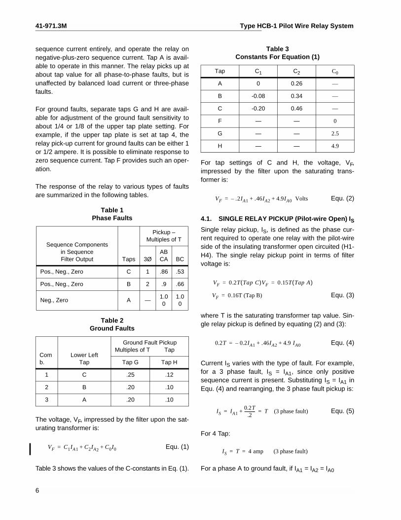
Table 1 Phase Faults
Sequence Componentsin SequenceFilter Output Taps
Pickup –Multiples of T
3ØABCA BC
Pos., Neg., Zero C 1 .86 .53
Pos., Neg., Zero B 2 .9 .66
Neg., Zero A —1.00
1.00
Table 2 Ground Faults
Comb.
Lower Left Tap
Ground Fault PickupMultiples of T Tap
Tap G Tap H
1 C .25 .12
2 B .20 .10
3 A .20 .10
VF C1IA1 C2IA2C0I0+ +=
Table 3 Constants For Equation (1)
Tap C1 C2 C0
A 0 0.26 —
B -0.08 0.34 —
C -0.20 0.46 —
F — — 0
G — — 2.5
H — — 4.9
VF .2IA1– .46IA2 4.9IA0 Volts+ +=
VF 0.2T Tap C( )VF 0.15T Tap A( )= =
VF 0.16T (Tap B)=
0.2T 0.2IA1– .46IA2 4.9 IA0+ +=
IS IA10.2T
.2-----------+ T (3 phase fault)= =
IS T 4 amp (3 phase fault)= =
6
Type HCB-1 Pilot Wire Relay System 41-971.3M
(IA2 is the phase A negative sequence current):
But:
So:
Equ. (6)
For T = 4
IS = 0.5
4.2. NOMINAL PICKUP (All Relays)
The nominal pickup, Inom, is defined as
Equ. (7)
Where Inom = total internal fault current
K = number of relays (2 or 3)
IS = single-relay pickup with pilotwire disconnected (see above)
0.2T .2IA1– .46IA2 4.9 IA0+ +=
IA10.2T5.2
----------- IA2 IA0= = =
IS IA1 IA2 IA0+= =
= 3IA1
0.2T( ) 3( )
IS 3IA10.2T 3×( )
5.2------------------------- 0.12T (A-G Fault)= = =
Inom KIS=
For example, in the previous example or a phase-A-ground fault, the single-relay pickup was determinedas IS = 0.5 ampere for 4CH taps with the pilot-wireopen. For a two-terminal line, the nominal pickup fora phase-A-to-ground fault (4CH taps) is:
4.3. MINIMUM TRIP (All Relays)
With equal inputs to all relays and zero pilot-wireshunt capacitance, the relays will operate at theirnominal pickup point. The minimum trip points willvary somewhat from nominal value, depending onthe pilot-wire constants and the magnitude andphase angle of the various relay input currents. Forexample, Figure 6 shows the relay operating pointsfor a two-terminal line, assuming input current onerelay only.
An example of the characteristics with various cur-rent distributions shown in Figure 6. The filter outputvoltage, VF, of each relay, as defined by equation (1)must be in phase or 180 degrees out-of-phase, inorder for Figure 7 to apply.
4.4. INSULATING TRANSFORMER
Unless otherwise noted, all characteristics presentedinclude an insulating transformer with each relay.Two ratios are available: 4/1 and 6/1. The high volt-age side (H1-H4 Terminals) is connected to the pilot-wires.
Inom A to G( ) 0.5 0.5 2× 1.0 ampere= = =
Sub 4183A61
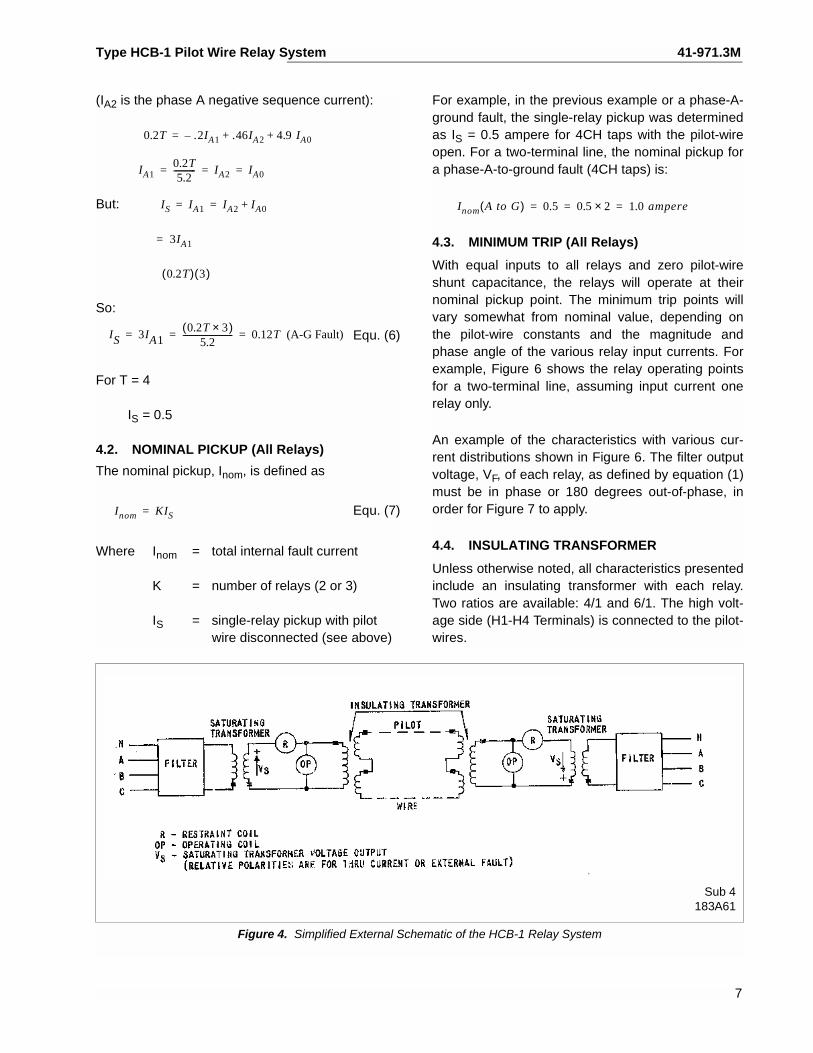
Figure 4. Simplified External Schematic of the HCB-1 Relay System
7
41-971.3M Type HCB-1 Pilot Wire Relay System
Sub 5183A062
Figure 5: Polar Unit Permanent Magnet Flux Paths
4.5. PILOT-WIRE REQUIREMENTS rise in station ground potential, should be less than
N
N
S
S
N
N
S
S
Moving Contact
Armature
PermanentMagnet
BALANCED AIR GAPS UNBALANCED AIR GAPS
N
AdditionalFlux Path
Shunt
The relays should not be applied with pilot-wireseries resistance or shunt capacitance exceeding thefollowing values:
RL = series loop resistance in ohms.
CS = total shunt capacitance in microfarads.(Total wire to wire capacitance)
Where the shunt capacitance exceeds the aboveamount, it may be feasible in some cases to provideshunt reactors to compensate for the excessivecapacitance. The amount of capacitance which canbe compensated is limited and varies dependingupon the magnitude of the pilot-wire distributedeffect.
A shielded, twisted pilot-wire pair, preferably of #19AWG or larger, is recommended; however, openwires may be used if they are frequently transposedin areas of exposure to power circuit induction. Thevoltage impressed across either insulating trans-former (H1-H4 Terminals) as a result of induction or a
Table 4 Insulating Transformer Rate
No. ofRelays
4/1 6/1
RL CS RL CS
2 2000 1.5 4500 0.33
3 500/LEG 1.8 1000/LEG 0.75
8
7.5 volts to prevent undesired relay operation.
For three-terminal applications, the loop resistance ofall legs of the pilot-wire must be balanced within 5percent, with variable resistors. The pilot-wire resis-tance to be balanced is divided by 16 and 36 for the 4to 1 and 6 to 1 ratio insulating transformers respec-tively, since the balancing resistors are located onthe relay side of the insulating transformers.
Induced voltages and rises in station-ground poten-tial may be handled by the following means:
Figure 6: Typical Curves Showing the Effect of the Pilot-wire on Minimum Trip Current, Two-Terminal Line (Maximum Resistant Tap). Insulating Transformer 4/1 ratio
Sub 1619594
Type HCB-1 Pilot Wire Relay System 41-971.3M
a) Neutralizing reactors may be connected inseries with the pilot to hold pilot-wire poten-tial close to the remote ground potential inthe presence of a rise in station-groundpotential. They do not limit pilot-wire voltagesto safe values in the presence of a longitudi-nal induced voltage. When using the neutral-izing reactor, the pilot-wire sheath should beinsulated from station ground to minimizesheath-to-pair potential. All other parts in thecable which are connected to station groundshould also be protected with neutralizingreactors to minimize pair-to-pair voltages.
b) Drainage reactors may be connected acrossthe pilot-wire to ground through a KX642 pro-tector tube. The drainage reactor is particu-larly effective in limiting pair-to-groundvoltage in the presence of an induced volt-age. When the tube flashes, both wires areconnected to ground through the drainagereactor windings which offer a low imped-ance to ground but maintain a high imped-ance to an ac voltage across the wires. Thus,the HCB-1 system will operate normally eventhough the protector tube has flashed over.The drainage reactor is not intended to han-dle a rise in ground potential.
c) The neutralizing and drainage reactors maybe utilized together. If the neutralizing reactoris to be of any value, the drainage reactorthrough the protector tube must be con-nected to remote ground.
For more information with reference to the insulationand protection equipment, refer to I.L. 41-971.4.
4.6. TRIP CIRCUIT
The main contacts will safely close 30 amperes at250 volts dc, and the seal-in contacts of the indicat-ing contactor switch will safely carry this current longenough to trip a circuit breaker.
The indicating contactor switch has two taps that pro-vide a pick-up setting of 0.2 or 2 amperes. To changetaps requires connecting the lead located in front ofthe tap block to the desired setting by means of ascrew connection.
5.0 SETTINGS
There are four settings in the relay. The correct tapsetting should be determined as outlined under sec-tion 5.2, “Setting Calculations”.
1) Restraint taps – maximum or minimum
To change taps, connect the lead in front ofthe relay to the correct tap.
2) T tap – 4, 5, 6, 7, 8, 10, and 12
3) R1 tap – A, B, C
4) R0 tap – R, G and H
5.1. INDICATING CONTACTOR SWITCH (ICS)
The only setting required on the ICS is the selectionof the 0.2 or 2.0 ampere tap setting. This selection ismade by connecting the lead located in front of thetap block to the desired setting by means of the con-necting screw.
5.2. SETTING CALCULATIONS
The HCB-1 relay has four sets of taps: R1, T, R0, andrestraint taps. The following discussion establisheslimits for the various tap settings under different oper-ating conditions. It should be kept in mind that set-tings to obtain operation on minimum internal faultconditions are based on the total fault current thatflows into the protected line from all terminals.
TERMS
A, B, C, D, F, G, H — Relay Taps
I3P – total minimum internal 3-phase sec-ondary fault current fed from all termi-nals, divided by the number ofterminals (2 or 3)
IL – maximum secondary load currentflowing through the protected line
Ig – total minimum secondary ground faultcurrent fed into the protected linefrom all terminals, divided by thenumber of terminals
Inom (P-P) – nominal internal phase-to-phase fault sensitivity.
Inom (P-G) – nominal internal line-to-groundfault sensitivity.
9
41-971.3M Type HCB-1 Pilot Wire Relay System
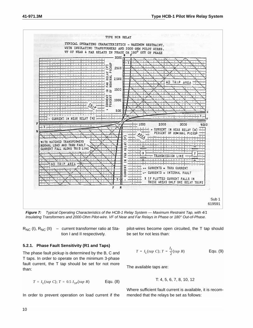
Sub 1619591
Figure 7: Typical Operating Characteristics of the HCB-1 Relay System — Maximum Restraint Tap, with 4/1Insulating Transformers and 2000-Ohm Pilot-wire. VF of Near and Far Relays in Phase or 180° Out-of-Phase.
RNC (I), RNC (II) – current transformer ratio at Sta- pilot-wires become open circuited, the T tap should
tion I and II respectively.5.2.1. Phase Fault Sensitivity (R1 and Taps)
The phase fault pickup is determined by the B, C andT taps. In order to operate on the minimum 3-phasefault current, the T tap should be set for not morethan:
Equ. (8)
In order to prevent operation on load current if the
be set for not less than:
Equ. (9)
The available taps are:
T: 4, 5, 6, 7, 8, 10, 12
Where sufficient fault current is available, it is recom-mended that the relays be set as follows:
T IL tap C( ) T; 0.5 I3P tap B( )= =
T IL tap C( ) T;IL
2---- tap B( )= =
10
Type HCB-1 Pilot Wire Relay System 41-971.3M
Equ. (10)
The taps must be set the same at all stations. Wherethe ct ratios are not identical use auxiliary ct’s tomatch the currents within 5% of each other.
5.2.2. Ground Fault Sensitivity (R0 TAP)
The ground-fault pickup is determined by G, H and Ttaps. (T should be determined by the phase setting.)The minimum fault current Ig should exceed the fol-lowing:
Tap A or B: Ig = .20T (Tap G); Ig = .10T (Tap H)Tap C: Ig = .25T (Tap G); Ig = .12T (Tap H)
For cable circuits, where the line charging currentexceeds 5% of nominal positive sequence pickupcurrent, set tap G; otherwise set tap H.
The taps must be set identically at all stations. Useauxiliary ct’s where the main ct’s have a differentratio. The currents should match within 5%.
5.2.3. Restraint Tap (Max. and Min. Taps)
Set in maximum restraint tap for all two-terminallines. Set in minimum restraint tap for all three termi-nal lines. The use of maximum restraint on two termi-nal applications allows the relay to be used for allpilot-wires as indicated in Table 4. The use of mini-mum restraint on three-terminal applications com-pensates for the desensitizing effect of a thirdterminal.
NOTE: The relay pick-up calibration will changeslightly (within 5%) between minimumrestraint tap and maximum restraint. Inmost applications, it is not necessary torecalibrate the relay when changing to theminimum restraint tap.
5.2.4. Tapped Loads
Where one transformer bank is tapped to a line pro-tected with two HCB-1 relays, the critical point is toset above the fault current flow for a fault on the otherside of the bank. Set the T for not less than:
Equ. (11)
where IPL = total secondary fault current feed fromall terminals to a phase-to-phase faulton the low side of the bank, divided bythe number of terminals (2 or 3).
NOTE: The tapped bank must not act as aground source for high-side faults. Ordi-narily this means that the R0 tap settings(G, H) need not be changed since no zero-sequence current flows in the line whenthe low side is grounded.
5.3. SETTING EXAMPLE
Assume:Two-terminal line.
ct ratio = 600/5Full-load current = IL = 400AMinimum 3-phase internal fault
current:Through Station I = 1500AThrough Station II = 2500A
Minimum internal line-to-ground faultcurrent:
Through Station I = 400AThrough Station II = 285A
5.3.1. Phase Fault Pickup
The phase fault current is sufficient to allow the relayto be set to prevent tripping on an open circuitedpilot-wire. Therefore, the desired taps would be:
Set both relays for T = 4, R1 = C
T 1.25 IL tap C( ) T; 0.62 IL tap B( )= =
T 1.91 IPL tap C( ) T; 1.52 IPL tap B( )= =
I max( ) I3P1500 2500+
2------------------------------x
5600--------- 16.7 tap C( )= = =
I max( ) 0.5I3P 8.3 tap B( )= =
I min( ) IL400120--------- 3.3 tap C( )= =
I min( )IL
2---- 1.7 tap B( )= =
T 1.25 IL 4.1 tap C( )= =
T 0.62 IL 2.0 tap B( )= =
11
41-971.3M Type HCB-1 Pilot Wire Relay System
The nominal 3-phase fault pick-up current from equa-tion 7 is:
5.3.2. Ground Fault Pickup
Set R0 = H
For line to ground fault:
5.3.3. Restraint Tap
Use maximum restraint tap.
6.0 INSTALLATION
The relays should be mounted on switchboard pan-els or their equivalent in a location free from dirt,moisture, excessive vibration, and heat. Mount therelay vertically by means of the four mounting holeson the flange for semi-flush mounting, or by means ofthe rear mounting stud or studs for projection mount-ing. Either a mounting stud or the mounting screwsmay be utilized for grounding the relay. The electricalconnections may be made directly to the terminals bymeans of screws for steel panel mounting or to theterminal studs furnished with the relay for thick panelmounting. The terminals stud may be easily removedor inserted by locking two nuts on the stud and thenturning the proper nut with a wrench.
For detailed flexitest case information, refer to I.L.41-076.
7.0 ACCEPTANCE TESTS
The following tests are recommended when the relayis received from the factory.
HCB-1 current pickup values will be within 5% toler-ance of the I.L. specification, only for those taps atwhich the relay is calibrated. For other tap settings,the tolerance may be higher than 5% of nominal,unless recalibration of the relay is performed.
The HCB-1 is factory calibrated at the following taps:
R1: “C” TapR0: “H” TapT “4” Amps
If other tap settings are used, the HCB-1 relay mustbe recalibrated at the applied settings to obtainpickup current within 5% of the I.L. specifications.
7.1. MAIN UNIT
Connect the relay to the insulating transformer asshown in Figure 8, and set C, H, 4 and maximumrestraint tap. With the insulating transformer termi-nals H1 and H4 open circuited, measure the mini-mum pick-up current I79 (min.), with current appliedthrough terminals 7 and 9. This value should not begreater than 2.25 amperes.
NOTE: The relay may operate at values of cur-rent lower than 2.25 amperes dependingupon the insulating transformer used andthe prior history of the polar unit. Thepickup should not be lower than 1.4amperes. To increase pickup, short H1-H4of insulating transformer, apply 40amperes momentarily to terminals 3 and5 of relay and check pickup of relay. Itshould be 2.12 + 5% amperes. If not, thepolar unit should be recalibrated per“Polar Unit Calibration.”
Now, connect a resistance, RPW, across H1 and H4of the insulating transformer, with a 10-mfd capacitorconnected between H2 and H3. Connect a capacitor.CPW in parallel with RPW. With RPW and CPW set asspecified in Table 5 suddenly apply I35 = 30 amperes(through terminals 3 and 5).
Inom 2T 8 amperes= =
Ig400 285+
2------------------------
5600---------× 2.85A= =
Inom 2 0.12 4×× 0.96A= =
Table 5
RPW TEST - Maximum Restraint TapR1 = C, R0 = H, T-4
InsulatingTransformer
RatioRPW
*
In Ohms
CPWin
Microfarads
4 to 16 to 1
1200 19002700 4300
0.750.33
12
Type HCB-1 Pilot Wire Relay System 41-971.3M
Sub 3293B225
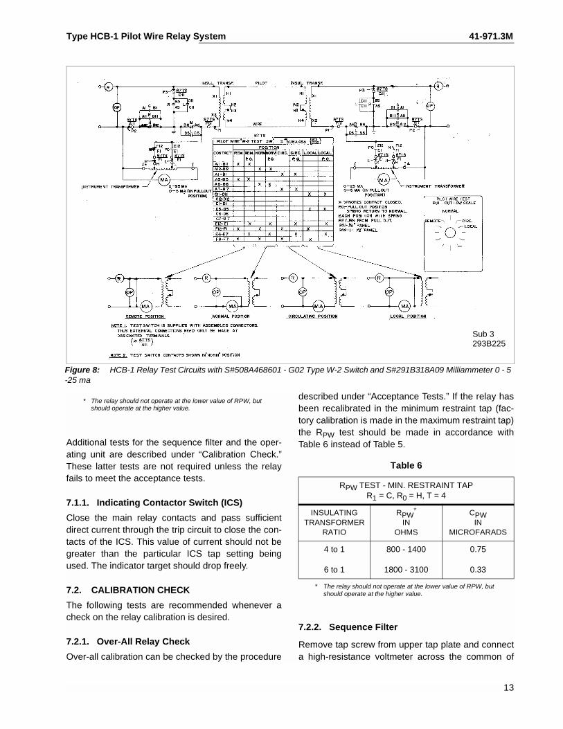
Figure 8: HCB-1 Relay Test Circuits with S#508A468601 - G02 Type W-2 Switch and S#291B318A09 Milliammeter 0 - 5 -25 ma
Additional tests for the sequence filter and the oper-ating unit are described under “Calibration Check.”These latter tests are not required unless the relayfails to meet the acceptance tests.
7.1.1. Indicating Contactor Switch (ICS)
Close the main relay contacts and pass sufficientdirect current through the trip circuit to close the con-tacts of the ICS. This value of current should not begreater than the particular ICS tap setting beingused. The indicator target should drop freely.
7.2. CALIBRATION CHECK
The following tests are recommended whenever acheck on the relay calibration is desired.
7.2.1. Over-All Relay Check
Over-all calibration can be checked by the procedure
described under “Acceptance Tests.” If the relay hasbeen recalibrated in the minimum restraint tap (fac-tory calibration is made in the maximum restraint tap)the RPW test should be made in accordance withTable 6 instead of Table 5.
7.2.2. Sequence Filter
Remove tap screw from upper tap plate and connecta high-resistance voltmeter across the common of
* The relay should not operate at the lower value of RPW, butshould operate at the higher value.
Table 6
RPW TEST - MIN. RESTRAINT TAPR1 = C, R0 = H, T = 4
INSULATINGTRANSFORMER
RATIO
RPW*
INOHMS
* The relay should not operate at the lower value of RPW, butshould operate at the higher value.
CPWIN
MICROFARADS
4 to 1
6 to 1
800 - 1400
1800 - 3100
0.75
0.33
13
41-971.3M Type HCB-1 Pilot Wire Relay System
the upper tap plate and Terminal 2. Energize therelay with 179 = 2.05 amperes (terminals 7 and 9).The measured open-circuit voltage, VF, should be:
VF = .8 ±5% volts with tap settings C and H. Repeatthis voltage measurement with I59 = 3.44 amperes.
7.2.3. Operating Unit
The following test will check the polar unit calibrationand the performance of the rectifiers. Connect a vari-able non-inductive resistor across the high-voltageterminals of the insulating transformer (H1 to H4),and connect dc millimeters in series with the operat-ing and restraining coils of the polar unit by openingthese circuits. (The restraint can be opened at thetap circuit for max. and min. restraint. The operatingcircuit has to be opened at the polar unit. The operat-ing coil terminals are the rear terminals of the polarunit.) These millimeters should have low resistanceand should be capable of reading in the order of 20to 25 mA in the operating coil and 100 to 150 mA inthe restraining circuit. Using C, H, and 4, energizethe relay with I35 = 10 amperes (terminals 3 and 5)and increase the variable resistance across the insu-lating transformer high-voltage terminals until therelay just trips. The values obtained should conformto the following equations:
For minimum restraint: IO = 0.12IR + 7
For maximum restraint: IO = 0.16IR + 7
where IO and IR are operating and restraining coilcurrents, respectively, in milliamperes. The resultsare subject to variations between individual relays,due to different exciting impedances of the insulatingtransformers. However, the value should never belower than:
For minimum restraint: IO = 0.12IR + 74
For maximum restraint: IO = 0.16IR + 4
7.3. CALIBRATION PROCEDURE
If the factory calibration has been disturbed, the fol-lowing procedure should be followed to recalibratethe relay.
7.3.1. Filter Calibration
This adjustment is performed by means of the taps
on the formed wire resistor (see Figure 2 for loca-tion).
1. Remove tap screw from upper tap plate and setlower tap screws in A and H.
2. Connect voltmeter (low-reading, high resistancerectox) across tap A and the common of theupper tap block.
3. Pass 10 amperes ac into terminal 7 and out ter-minal 5 of the relay and record voltage (voltageshould be .70 to .80).
4. Remove voltmeter leads and connect them tonon-adjustable point of formed resistor in rear ofrelay and the front of left-hand tube resistor.(F.V.)
5. Adjust upper adjustable point of formed resistoruntil voltmeter reads 1.73 times voltage of step 3.
6. Check calibration
a) Set taps on C and H. (T tap removed) pass10 amps. into terminal 7 and out terminal 9.Measure the voltage across terminal 5 andcommon of upper tap block. (Should bebetween 3.8 and 4.0 volts.)
b) Pass 10 amperes into terminal 5 and out ter-minal 7. Measure voltage across non-adjust-able point of formed resistor in rear of relayand the front screw of left-hand tube resistor(F.V.). Voltage should be equal to 1/3 of volt-age of step 6a.
7. Connect voltmeter to middle adjustable point andupper adjustable point of formed resistor.
8. Pass 10 amperes into terminal 5 and out terminal7.
9. Adjust middle adjustable point until voltageequals 1/3 of that of step 4.
7.3.2. R0 Taps
No adjustments can be made on the R0 resistors.Value of resistance can be checked by passing 5amperes ac through terminal 3 and out terminal 5. Ttap must be disconnected. Following voltages shouldbe measured across terminal 2 and the specified tapof R0.
R0 Tap Setting Volts ac
GH
3.8 to 4.27.6 to 8.4
14
Type HCB-1 Pilot Wire Relay System 41-971.3M
7.3.3. Polar Unit Contact Adjustment
Place a .088 to .095 inch feeler gage between theright-hand pole face on the armature. This gapshould be measured near the front of the right-handpole face. Bring up the backstop screw until it justmakes with the moving contact. Place .045 to .050gage between moving contact and the stationarycontact on the left-hand side of the polar unit. Bringup the stationary contact until it just makes with thegage and lock in place. For relays with double con-tacts make sure that both upper and lower contactsmake at the same time.
7.3.4. Polar Unit Calibration
Connect the restraint tap link in the position in whichit will be used. Connect terminals X1 and X2 of theinsulating transformer across the pilot-wire terminalsof the relay. Connect the relay taps on 4, C, and H.
The sensitivity of the polar unit is adjusted by meansof two magnetic, screw-type shunts at the rear of theunit. Looking at the relay front view, turning out theright-hand shunt decreases the amount of currentrequired to close to the right-hand stop. Conversely,drawing out the left-hand shunt decreases theamount required to trip the relay. In general, thefather out the shunt screws are turned, the greaterthe toggles action will be and as a result, the dropoutcurrent will be lower. In adjusting the polar units, besure that a definite toggle action is obtained, ratherthan a gradual movement of the armature.
Start with both shunts out 4 to 5 turns. Short out thepilot-wire on the high side of the insulating trans-former. Momentarily apply 40 amperes from termi-nals 5 to 3. Now remove the short from H1 to H4 andapply current to terminals 7 and 9. Adjust the shuntsat the rear of the polar unit such that the unit oper-ates at 2.10 to 2.15 amperes and resets at 1.0amperes or higher.
NOTE: Right-hand shunt controls pickup whileleft-hand shunt controls dropout.
After this adjustment is complete, short out pilot-wireand apply 40 amperes momentarily from terminals 5to 3. Now remove the short from H1 to H4 and checkpickup for I79. If value has changed from before, it willbe necessary to re-adjust the right-hand shunt. Sev-
eral trials may be necessary before the relay willpickup at 2.10 amperes and dropout at 1.0 amperesor higher. In each case, 40 amperes should beapplied to terminal 5 and 3 with the H1 and H4 termi-nals shorted before any additional adjustments areperformed on the shunt.
After the shunts have been adjusted, apply 40amperes momentarily to terminals 3 and 5 of therelay with the pilot-wire open. Pickup will be approxi-mately 1.4 amperes with current applied to terminals7 and 9. This change in pickup is due to a change inthe residual magnetism in the polar unit of the relay.In the de-energized state, the permanent magnet ofthis unit produces a flux or magnetic bias to keep thecontacts open. When the unit is energized, a secondflux (electrical) is produced which either adds to orsubtracts from the magnetic flux. When the electricalflux is removed, the magnetic structure of the polarunit is changed. Hence, the flux produced by anexcess of restraint current, adds to the magneticbias, and the flux produced by an excess of operat-ing current subtracts from the magnetic bias. Thischaracteristic is inherent in the polar unit and has noeffect on the overall performance of the relay.
After the shunt adjustment has been made, changethe input current connections to terminals 3 and 5.Apply 40 amperes momentarily with H1 and H4 ter-minals shorted. Remove short and measure pickupwith current applied to terminals 3 and 5. The relayshould trip with I35 = 0.45 to 0.55 amperes.
8.0 ROUTINE MAINTENANCE
8.1. CONTACTS
All contacts should be cleaned periodically. A contactburnisher, style number 182A836H01, is recom-mended for this purpose. The use of abrasive mate-rial for cleaning is not recommended, because of thedanger of embedding small particles in the face ofthe soft silver and thus impairing the contact.
8.2. ICS UNIT
Close the main relay contacts and pass sufficientdirect current through the trip circuit to close the con-tacts of the ICS. This value of current should not begreater than the particular ICS tap setting beingused. The indicator target should drop freely.
15
41-971.3M Type HCB-1 Pilot Wire Relay System
8.3. OPERATING UNIT
Check the relay minimum pick-up with the pilot-wiresdisconnected from terminals H1 and H4 of the insu-lating transformer, by energizing with I79 current (ter-minals 7 and 9). Pick-up current should be:
I79 (MIN) = .53 T ±5% amperes
Additional tests are recommended with the pilot-wireconnected as described under “Complete SystemTest”.
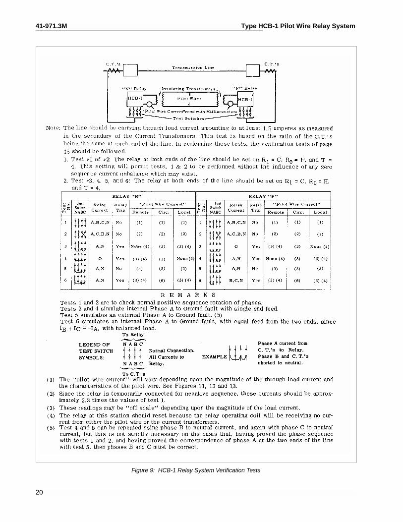
9.0 COMPLETE SYSTEM TEST
At the time of the initial installation and at subsequentmaintenance periods, it is recommended that the fol-lowing relay system checks be made, with the pilot-wire connected.
9.1. MINIMUM PICKUP
! CAUTION
In making this test with the relay in place on
the switchboard, it is necessary to connect
the load box in the circuit between the relay
and the “HOT” side of the supply circuit. If
this precaution is not observed, it is possible
to cause a short circuit between the grounded
station service supply circuit and the ground
of the current transformer circuit.
The minimum pickup of each relay should bechecked before starting the system tests. With taps4CH, as specified in Figure 9, and the pilot-wire cir-cuit open on the high side of the insulating trans-former, each relay should trip with IAN = 0.45 to 0.55amp or with IBC = 2.10 to 2.15 amp.
With the pilot-wire connected, energize one relaywith IAN and determine the minimum pick-up of allrelays. Repeat this test by energizing the other relayor relays. Record these values for future reference.
9.2. VERIFICATION CIRCUIT TESTS (Ref. Figure 9)
In performing these tests, the following procedureshould be used.
1. Standard testing equipment is recommended forpermanent installation with the relays as shownin Figure 8. If this equipment is not available, asimilar portable test should be set up using alow-resistance ac milliammeter.
2. Red handle flexitest case switch should be opento interrupt the breaker trip circuit.
3. A test crew is necessary at each substation witha means of communication between them.
4. When the test calls for delivering only specifiedcurrents to the relay, it is necessary to use a thinpiece of insulating material in the ammeter testjack. For example, test #5 of Figure 9 relay “N”.To apply phase A to N current to the near relayonly, the switches associated with terminals 6, 7,8, 9 of Figure 3 must be open. Opening switches6 and 8 short circuits the current transformers forphases B and C. However, it is also necessaryto insert the insulating material in the amme-ter test jacks associated with terminals 7 and9 in order to break up the connectionbetween the filter in the relay chassis and thegrounded input circuits from current trans-former circuits from current transformers inphases B and C.
5. To facilitate making test #2 of Figure 9 twoammeter test plugs wired together with a foot ortwo of flexible wire should be used. With thesetwo test plugs suitably wired together, one ofthem may be shoved in the ammeter test jackassociated with terminal 9, Figure 3. (This shouldnot be done until the switches for terminals 6 and8 have been open, thus short circuiting the cur-rent transformers involved). It is desirable to wirethe test plugs together such that when one isshoved in the one ammeter test jack with the redside up, and the other is shoved in the otherammeter test jack with the black side up, it isthen known that the B and C phase currents tothe relay have been reserved at the input to thechassis in line with test #2, Figure 9. After thesetest plugs are properly inserted, it is then appro-priate to close the switches associates with theterminals 6 and 8, Figure 3, in order to removethe short circuit from the current transformer sec-ondaries.
16
Type HCB-1 Pilot Wire Relay System 41-971.3M
Perform the tests as indicated in Figure 9 recordingthe milliammeter readings and the relay input currentat the same instant, for future reference. The head-ings “Circulating” and “Remote” in the table of Figure9 refer to the test switch positions, “CIRC” and“REM.” For tests 3 to 6 of Figure 9, the input currentshould be increased to about 1.5 amperes by an aux-iliary current transformer, if the secondary load cur-rent is below this value. Also record the input andoutput readings with the test switch in the “Local”position. Typical values for the “Local” position read-ings are shown in Figure 13.
9.3. THREE TERMINAL LINES
A similar procedure to Figure 9 should be followedfor three-terminal line applications. In this case openthe line circuit breaker at one terminal, and discon-nect the leads from the pilot-wire terminals to theinsulating transformer (open H1 and H4) at the thatterminal. This leaves the remaining position of theline operating as a two terminal line. Now perform thenormal tests as outlined for the two terminal line sys-tem test. When these tests have been satisfactorilycompleted, return the third terminal relay to normaland close the breaker at that station. Repeat theabove procedure with a different breaker open andrelay disconnected. This will complete the check ofthe three terminal line.
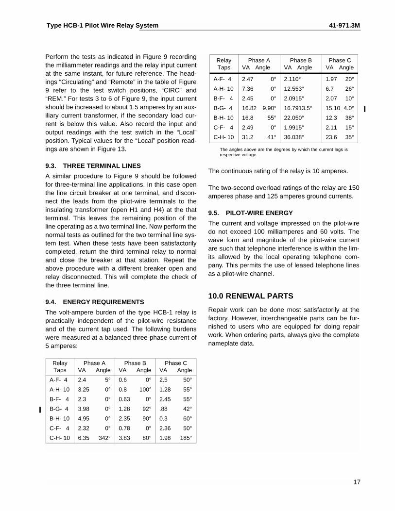
9.4. ENERGY REQUIREMENTS
The volt-ampere burden of the type HCB-1 relay ispractically independent of the pilot-wire resistanceand of the current tap used. The following burdenswere measured at a balanced three-phase current of5 amperes:
The angles above are the degrees by which the current lags isrespective voltage.
The continuous rating of the relay is 10 amperes.
The two-second overload ratings of the relay are 150amperes phase and 125 amperes ground currents.
9.5. PILOT-WIRE ENERGY
The current and voltage impressed on the pilot-wiredo not exceed 100 milliamperes and 60 volts. Thewave form and magnitude of the pilot-wire currentare such that telephone interference is within the lim-its allowed by the local operating telephone com-pany. This permits the use of leased telephone linesas a pilot-wire channel.
10.0 RENEWAL PARTS
Repair work can be done most satisfactorily at thefactory. However, interchangeable parts can be fur-nished to users who are equipped for doing repairwork. When ordering parts, always give the completenameplate data.
RelayTaps
Phase AVA Angle
Phase BVA Angle
Phase CVA Angle
A-F- 4
A-H- 10
B-F- 4
B-G- 4
B-H- 10
C-F- 4
C-H- 10
2.4 5°
3.25 0°
2.3 0°
3.98 0°
4.95 0°
2.32 0°
6.35 342°
0.6 0°
0.8 100°
0.63 0°
1.28 92°
2.35 90°
0.78 0°
3.83 80°
2.5 50°
1.28 55°
2.45 55°
.88 42°
0.3 60°
2.36 50°
1.98 185°
RelayTaps
Phase AVA Angle
Phase BVA Angle
Phase CVA Angle
A-F- 4
A-H- 10
B-F- 4
B-G- 4
B-H- 10
C-F- 4
C-H- 10
2.47 0°
7.36 0°
2.45 0°
16.82 9.90°
16.8 55°
2.49 0°
31.2 41°
2.110°
12.553°
2.0915°
16.7913.5°
22.050°
1.9915°
36.038°
1.97 20°
6.7 26°
2.07 10°
15.10 4.0°
12.3 38°
2.11 15°
23.6 35°
17
41-971.3M Type HCB-1 Pilot Wire Relay System
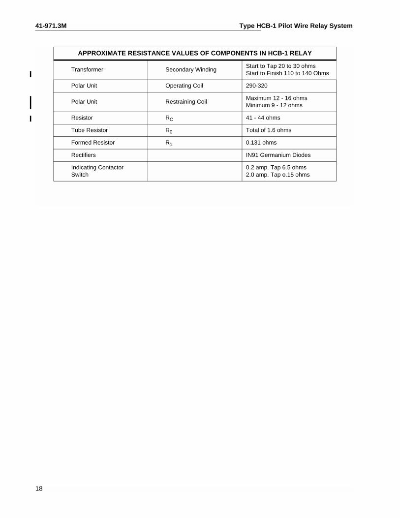
APPROXIMATE RESISTANCE VALUES OF COMPONENTS IN HCB-1 RELAY
Transformer Secondary WindingStart to Tap 20 to 30 ohmsStart to Finish 110 to 140 Ohms
Polar Unit Operating Coil 290-320
Polar Unit Restraining CoilMaximum 12 - 16 ohmsMinimum 9 - 12 ohms
Resistor RC 41 - 44 ohms
Tube Resistor R0 Total of 1.6 ohms
Formed Resistor R1 0.131 ohms
Rectifiers IN91 Germanium Diodes
Indicating ContactorSwitch
0.2 amp. Tap 6.5 ohms2.0 amp. Tap o.15 ohms
18

Type HCB-1 Pilot Wire Relay System 41-971.3M
19
THIS SPACE RESERVED FOR NOTES
41-971.3M Type HCB-1 Pilot Wire Relay System
20
Figure 9: HCB-1 Relay System Verification Tests
Type HCB-1 Pilot Wire Relay System 41-971.3M
21
41-971.3M Type HCB-1 Pilot Wire Relay System
22
Figure 10: Typical HCB-1 Relay System
Type HCB-1 Pilot Wire Relay System 41-971.3M
23
Sub 15 - 4810D98
41-971.3M Type HCB-1 Pilot Wire Relay System
Sub 1 Sub 1538101
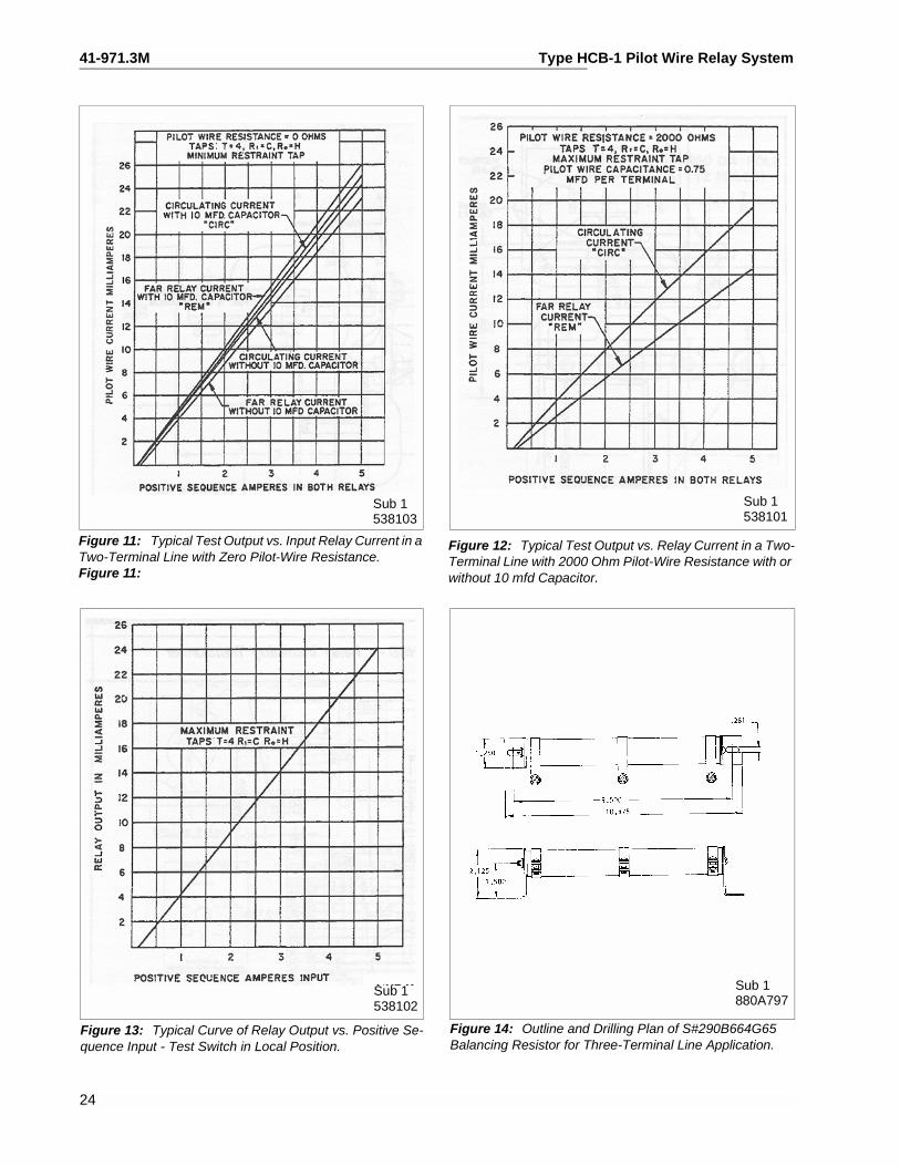
Figure 11: Typical Test Output vs. Input Relay Current in a Two-Terminal Line with Zero Pilot-Wire Resistance.Figure 11:
538103
24
Sub 1538102
Figure 12: Typical Test Output vs. Relay Current in a Two-Terminal Line with 2000 Ohm Pilot-Wire Resistance with or without 10 mfd Capacitor.
Sub 1880A797
Figure 13: Typical Curve of Relay Output vs. Positive Se-quence Input - Test Switch in Local Position.
Figure 14: Outline and Drilling Plan of S#290B664G65 Balancing Resistor for Three-Terminal Line Application.
Type HCB-1 Pilot Wire Relay System 41-971.3M
Sub 213C5342
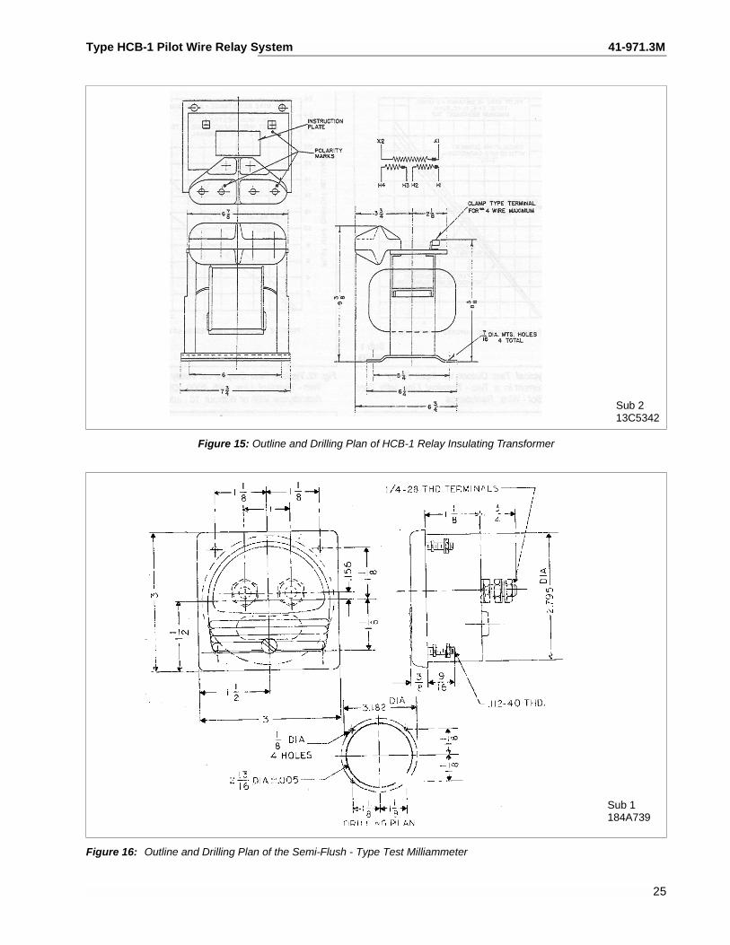
Figure 15: Outline and Drilling Plan of HCB-1 Relay Insulating Transformer
Sub 1184A739
Figure 16: Outline and Drilling Plan of the Semi-Flush - Type Test Milliammeter
25
41-971.3M Type HCB-1 Pilot Wire Relay System
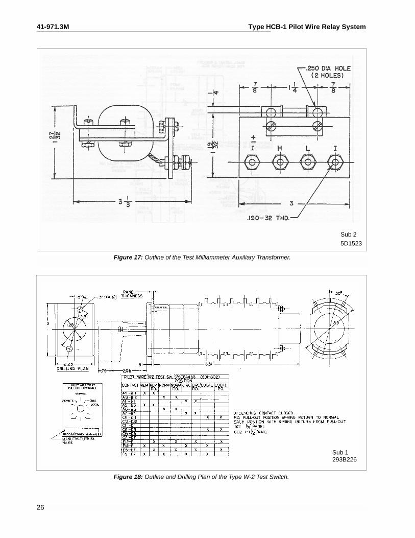
5D1523
Sub 2
Figure 17: Outline of the Test Milliammeter Auxiliary Transformer.
Sub 1293B226
Figure 18: Outline and Drilling Plan of the Type W-2 Test Switch.
26

Type HCB-1 Pilot Wire Relay System 41-971.3M
27
THIS PAGE RESERVED FOR NOTES
41-971.3M Type HCB-1 Pilot Wire Relay System
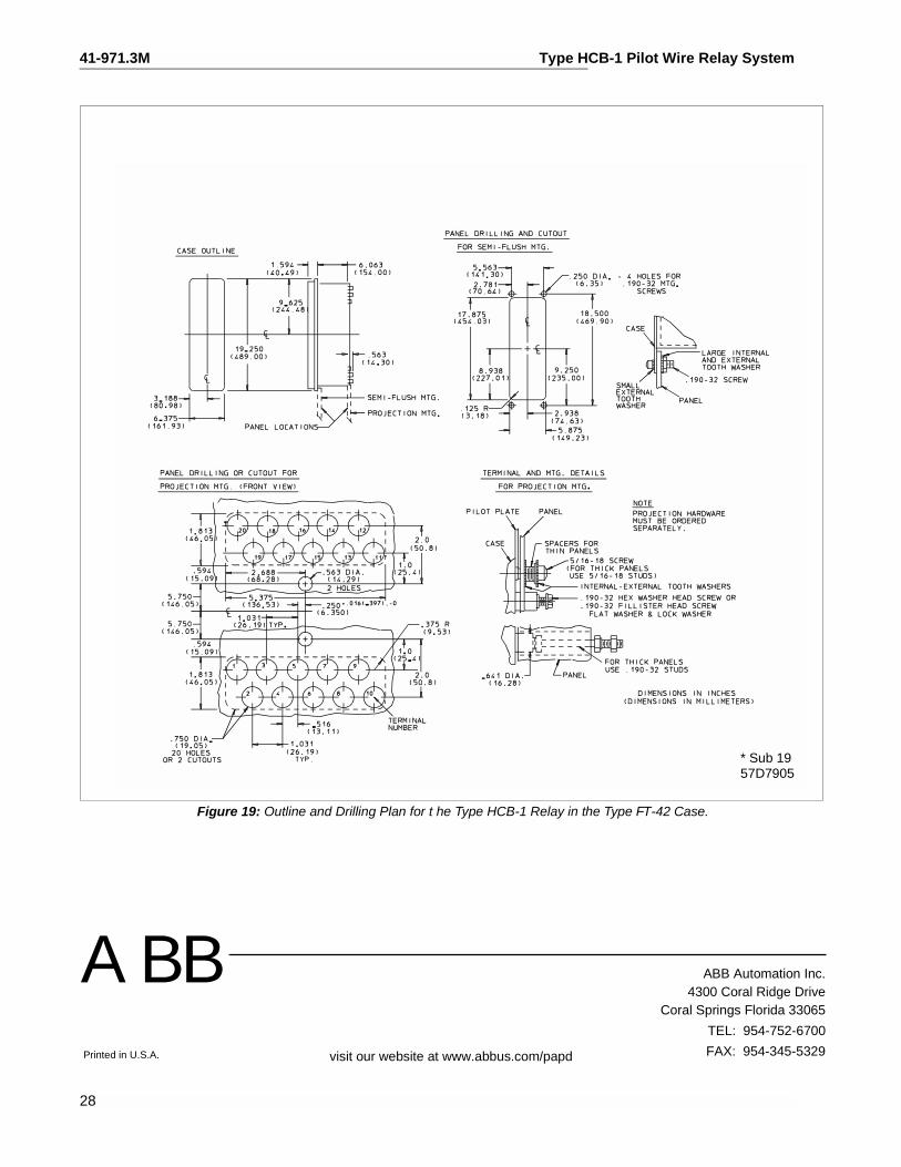
* Sub 1957D7905
Figure 19: Outline and Drilling Plan for t he Type HCB-1 Relay in the Type FT-42 Case.
28
Printed in U.S.A.
ABB Automation Inc.4300 Coral Ridge Drive
Coral Springs Florida 33065
TEL: 954-752-6700
FAX: 954-345-5329
ABB
visit our website at www.abbus.com/papd