effects of cutting tool coating on surface
TRANSCRIPT
EFFECTS OF CUTTING TOOL COATING ON SURFACE ROUGHNESS IN
MACHINING PRE-HARDENED STEEL (P20)
AINI RUSHDA BINTI MD DESA
A thesis submitted is fulfillment of the requirements for the award of the degree of
Bachelor of Manufacturing Engineering
Faculty of Manufacturing Engineering
Universiti Malaysia Pahang
JUNE 2012
vi
ABSTRACT
Quality of surface roughness is one of the challenges in the industry to produce
high quality products. Cutting parameters and type of cutting tools are the factors that
affect the quality of surface roughness. The purpose of this study is to examine the
influences of different types of cutting tools coating and cutting parameters on the
surface roughness. The cutting tools used are (TiN, TiCN and TiAlN). Taguchi method
is used with three factors and three levels which is spindle speed (500. 1000, 1500) rpm,
feed rate (500, 800, 1000) mm/min and diameter tool size (8, 10, 12) mm. The
experimental results showed that, with larger diameter tool size the value of surface
roughness will decrease. Same goes to spindle speed. When increasing spindle speed
from (500-1500) rpm, the value of surface roughness also decreases. Different results
surface roughness in feed rate, lower feed rate will produce better surface roughness.
With suitable cutting parameters, TiAlN showed in decreasing surface roughness
compare to the other two types of cutting tools. Confirmation test had verified that
Taguchi design was successful in investigating the effect type of cutting tool coating on
the surface roughness.
vii
ABSTRAK
Kualiti kekasaran permukaan adalah salah satu cabaran dalam industri untuk
menghasilkan produk yang berkualiti tinggi. Parameter mesin dan jenis salutan pada
alat pemotong adalah faktor yang memberi kesan pada kekasaran permukaaan. Tujuan
kajian ini adalah untuk mengkaji pengaruh jenis salutan pada alat pemotong dan
parameter mesin terhadap kekasaran permukaan. Alat pemotong yang di gunakan ialah
(TiN, TiCN, TiAlN). Kaedah Taguchi di gunakan dengan menggunakan tiga faktor dan
tiga tahap bagi kelajuan penggumpar (500, 1000, 1500) rpm, kadar suapan (500, 800,
1000) mm/min dan saiz alat pemotong (8, 10, 12) mm. Keputusan eksperimen
menunjukkan apabila menggunakan saiz alat pemotong yang besar, nilai kekasaran
permukaan juga akan berkurang. Apabila kelajuan alat pemotong tinggi dari (500-1500)
rpm, nilai kekasaran permukaan juga akan berkurang. Keputusan kekasaran permukaan
berbeza pada kadar suapan, kadar suapan yang lebih rendah akan menghasilkan
kekasaran permukaan yang lebih baik. Dengan menggunakan parameter yang sesuai,
TiAlN menghasilkan kekasaran permukaan yang lebih baik berbanding menggunakan
dua lagi jenis salutan alat pemotong. Ujian pengesahan yang di lakukan mengesahkan
bahawa kaedah Taguchi yang digunakan berjaya dalam mengkaji kesan jenis salutan
alat pemotong pada kekasaran alat pemotong.
viii
TABLE OF CONTENTS
PAGE
ACKNOWLEDGEMENT
ABSTRACT
ABSTRAK
TABLE OF CONTENTS
LIST OF TABLES
LIST OF FIGURES
LIST OF ABBREVIATION
v
vi
vii
viii
xi
xiii
xv
CHAPTER 1
INTRODUCTION
1.1 PROJECT MOTIVATION
1.2 PROJECT BACKGROUND
1.3 PROBLEM STATEMENT
1.4 PROJECT OBJECTIVES
1.5 PROJECT SCOPES
1.6 REPORT ORGANIZATION
1
1
2
2
3
4
CHAPTER 2 LITERATURE REVIEW
2.1 MILLING MACHINE
2.1.1 Milling Process
2.1.2 Milling Parameters
2.2 MILLING CUTTER
2.2.1 End Mill
2.2.2 Coated Milling Cutter
2.3 SURFACE ROUGHNESS
2.4 TAGUCHI METHOD
2.5 PRE-HARDENED STEEL (P20)
5
5
9
10
10
11
13
15
16
ix
CHAPTER 3 METHODOLOGY
3.1 INTRODUCTION
3.2 MATERIAL SELECTION
3.3 EXPERIMENTAL
3.3.1 Determining suitable working levels of the
design factors
3.3.2 Selecting proper orthogonal array
3.3.3 Experiment
3.3.4 Data Analysis
3.3.5 Verification Test
18
20
21
23
23
24
26
27
CHAPTER 4 DATA ANALYSIS AND DISCUSSION
4.1 INTRODUCTION
4.2 REGRESSION ANALYSIS
4.2.1 TiN coated cutting tool
4.2.2 TiCN coated cutting tool
4.2.3 TiAlN coated cutting tool
4.3 EFFECT OF PROCESS PARAMETER ON
SURFACE ROUGHNESS
4.3.1 TiN coated cutting tool
4.3.2 TiCN coated cutting tool
4.3.3 TiAlN coated cutting tool
4.4 ANALYSIS OF SIGNAL TO NOISE
4.4.1 TiN coated cutting tool
4.4.2 TiCN coated cutting tool
4.4.3 TiAlN coated cutting tool
4.5 ANALYSIS OF VARIANCE (ANOVA)
4.5.1 TiN coated cutting tool
4.5.2 TiCN coated cutting tool
4.5.3 TiAlN coated cutting tool
28
30
31
32
34
35
35
36
37
38
39
40
42
43
44
46
47
x
4.6 VERIFICATION TEST
4.6.1 TiN coated cutting tool
4.6.2 TiCN coated cutting tool
4.6.3 TiAlN coated cutting tool
4.7 EFFECT OF TYPE OF CUTTING
TOOLS COATING
49
49
50
51
52
CHAPTER 5 CONCLUSION AND FUTURE WORK
5.1 INTRODUCTION
5.2 CONCLUSION
5.3 RECOMMENDATION FOR FUTURE
STUDY
54
54
55
REFERENCES
56
xi
LIST OF TABLES
Table No. Title Page
2.1 Characteristic of TiN
12
2.2 Characteristic of TiCN
12
2.3 Characteristic of TiAlN
13
2.4 Machining Recommendations
17
3.1 Typical Chemical Analysis
20
3.2 Physical Properties
20
3.3 Physical Properties
21
3.4 Mechanical properties
21
3.5 Factors and Levels
23
3.6 Orthogonal Array
24
3.7 Parameter Setting At Surface Roughness Tester
(Surfcom 130a)
25
3.8 Optimal Cutting Parameter
27
4.1 Surface Roughness Result and S/N Ratio for TiN
29
4.2 Surface Roughness Result S/N Ratio for TiCN
29
4.3 Surface Roughness Result S/N Ratio for TiAlN
30
4.4 Regression Analysis
31
4.5 Regression Analysis For TiCN
32
4.6 Regression Analysis For TiAlN
34
4.7 Response Table for S/N Ratios
39
4.8 Response Table For S/N Ratios (TiCN)
40
4.9 Response Table For S/N Ratios (TiAlN)
42

xii
4.10
Analysis of Variance for Mean Ra, Using Adjusted Ss for
Tests (TiN)
44
4.11 Analysis of Variance for Mean Ra, Using Adjusted Ss for
Tests (TiCN)
46
4.12 Analysis of Variance for Mean Ra, Using Adjusted Ss for
Tests (TiAlN)
47
4.13 Result of the Verification Test for Surface Roughness
49
4.14 Result of the Verification Test for Surface Roughness
50
4.15 Result of the Verification Test for Surface Roughness
51
xiii
LIST OF FIGURES
Figure No.
Title
Page
2.1 Milling process
6
2.2 Milling process
7
2.3 Milling process
8
2.4 Nomenclature of End Mill
11
2.5 Elements of Machined Surface Texture
14
3.1 Flow chart of overall methodology
19
3.2 Taguchi Design Procedure
22
3.3 Surface Roughness Tester (Surfcom 130a)
25
3.4 Measurement Surface Roughnes
26
4.1 Normal Probability Plot for TiN
31
4.2 Normal Probability Plot for TiCN
33
4.3 Normal Probability for TiAlN
34
4.4 Mean Surface Roughness vs. Spindle Speed, Feed Rate, and
Tool Size (TiN)
35
4.5 Mean Surface Roughness vs. Spindle Speed, Feed Rate, and
Tool Size (TiCN)
37
4.6 Mean Surface Roughness vs. Spindle Speed, Feed Rate, and
Tool Size (TiAlN)
37
4.7 S/N Ratios vs. Spindle Speed, Feed Rate, and Tool Size (TiN)
39
4.8 S/N Ratios vs. Spindle Speed, Feed Rate, and Tool Size
(TiCN)
41
4.9 S/N Ratios vs. Spindle Speed, Feed Rate, and Tool Size
(TiAN)
42

xiv
4.10 Normal Probabilty Plot (TiN)
45
4.11 Normal Probabilty Plot (TiCN)
46
4.12
Normal Probabilty Plot (TiAlN)
48
4.13 Surface Roughness Vs Spindle Speed (TiN, TiCN, TiAlN)
52
4.14 Surface Roughness Vs Feed Rate (TiN, TiCN, TiAlN)
52
4.15 Surface Roughness Vs Diameter Tool Size (TiN, TiCN,
TiAlN)
53
xv
LIST OF ABBREVIATIONS
FYP Final year project
TiN Titanium Nitride
TiCN Titanium Carbonitride
TiAlN Titanium Aluminum Nitride
N Spindle Speed
fr Feed Rate
C Carbon
Si Silicone
Mn Mangan
Cr Chromium
Mo Molybdenum
ANOVA Analysis Of Variance
v Spindle Speed (rpm)
f Feed Rate (mm/min)
d Diameter Tool Size (mm)
DF Degree of Freedom
Adj SS Adjust Sum Square
Adj MS Adjust Mean Square
F Fisher’s Ratio
P Probabilty Value
CHAPTER 1
INTRODUCTION
1.1 PROJECT MOTIVATION
Surface finish is one of the important factor or requirement from the customer. The
quality of the surface roughness is important to produce a precision mold. Without
precision molds, there is no quality in producing a plastic product. This will adversely
affect the industry. It is important to give a good characteristic of a part or product. A good
characteristic is like a lower contact surface friction, light reflection, coating and resisting
fatigue. Without lower surface roughness, all stated characteristics cannot be achieved.
Therefore, a suitable cutting tool and cutting parameter is important to produce a better
surface roughness.
1.2 PROJECT BACKGROUND
Milling machine is used to machine a solid material. In manual condition, milling
machine can be used to machine any objects that are not axially symmetric. It also used to
remove the unwanted material. Milling machine was widely used in many manufacturing
industries including the aerospace and automotive sector. (Mike S.L et al, November 1998)
2
In this sector, quality plays an important role in increasing the productivity of the
product. Surface finish or surface roughness is characteristic of the workpiece after
machining. There are several factors that can affect the quality of surface roughness which
is cutting speed, feed rate, depth of cut, type of tool and tool size (Mike S.L et al.,
November 1998).
Many research have been done to study the surface roughness. The studies used
different methods towards the surface roughness. The methods are mathematical modeling
and stylus profiler. By this method, the surface roughness can be measured.
1.3 PROBLEM STATEMENT
Several factors will affect the final result of surface roughness in CNC milling
operation. The uncontrollable factor such as tool geometry, tool wear, chip loads and chip
formation are the factor resulting in poor surface roughness. During the milling operation,
chatter or vibration of the machine tool and wear will contribute to the damage of surface
roughness.
The main point is stressed in this research is to choose a suitable cutting tool with a
suitable parameter to produce a fine surface finish. Improper process parameters cause
losses such as rapid tool wear and tool fracture besides the economic losses including
spoiled workpiece or reduced surface quality (Gokkaya, H. et al. 2005).
The purpose of this research is to study the effect of the different type of cutting
tools coating to the surface roughness together with the cutting parameters.
1.4 PROJECT OBJECTIVE
The objective of this research is to know the factors that affect surface roughness for
machining the pre-hardened steel (P20). From the previous research had proved that
different cutting tool coating produced different surface roughness. Beside that there are
3
many machining parameters that are also contributing in the influenced of surface
roughness.
These are the objectives of this research.
1. To study more about CNC milling machine
2. To analyze the effect of different type of cutting tools coating on the surface
roughness
3. To determine the optimum cutting parameters in machining to produce better
surface roughness.
1.5 PROJECT SCOPE
The scope of this project covers several issues from the milling machine, cutting
tools coating used and the analysis.
1. Different type of cutting tools coating.
Three types of cutting tool coating are used to determine the best type of cutting
tool coating to produce the best surface roughness.
2. Machining parameters.
Three types of machining parameters which is spindle speed, feed rate and
diameter tool size is used to determine the optimal machining cutting for these
parameters.
3. Machining conditions.
Three level machining parameters are used which is high level, medium level
and low level.
4
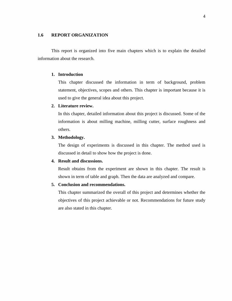
1.6 REPORT ORGANIZATION
This report is organized into five main chapters which is to explain the detailed
information about the research.
1. Introduction
This chapter discussed the information in term of background, problem
statement, objectives, scopes and others. This chapter is important because it is
used to give the general idea about this project.
2. Literature review.
In this chapter, detailed information about this project is discussed. Some of the
information is about milling machine, milling cutter, surface roughness and
others.
3. Methodology.
The design of experiments is discussed in this chapter. The method used is
discussed in detail to show how the project is done.
4. Result and discussions.
Result obtains from the experiment are shown in this chapter. The result is
shown in term of table and graph. Then the data are analyzed and compare.
5. Conclusion and recommendations.
This chapter summarized the overall of this project and determines whether the
objectives of this project achievable or not. Recommendations for future study
are also stated in this chapter.
CHAPTER 2
LITERATURE REVIEW
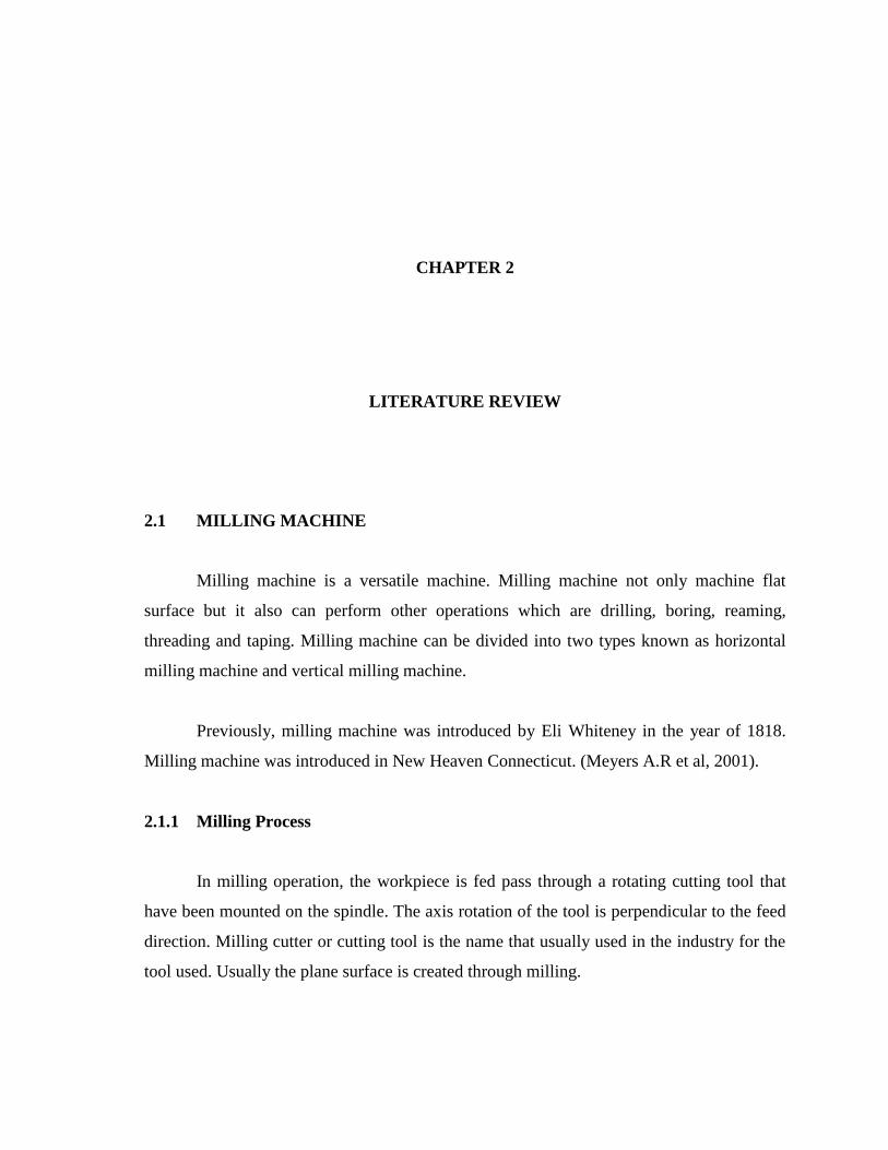
2.1 MILLING MACHINE
Milling machine is a versatile machine. Milling machine not only machine flat
surface but it also can perform other operations which are drilling, boring, reaming,
threading and taping. Milling machine can be divided into two types known as horizontal
milling machine and vertical milling machine.
Previously, milling machine was introduced by Eli Whiteney in the year of 1818.
Milling machine was introduced in New Heaven Connecticut. (Meyers A.R et al, 2001).
2.1.1 Milling Process
In milling operation, the workpiece is fed pass through a rotating cutting tool that
have been mounted on the spindle. The axis rotation of the tool is perpendicular to the feed
direction. Milling cutter or cutting tool is the name that usually used in the industry for the
tool used. Usually the plane surface is created through milling.

6
Many operations can be performed by using a milling machine. Each of these
operations needs a suitable milling cutter in machining. It is important to use a suitable size
of milling cutter because the size of milling cutter can also contribute to the machining
surface finishing. The cutting tools with greater radius cause smaller surface roughness
values (Tawfiq, 2008).
Before the machining operations were started, a suitable material and cutting tool
must be chosen to withstand cycles of impact forces and thermal shocked (Marinov.V.
2011). Different types of milling operations are shown in Figure 2.1.
FIGURE 2.1: Milling Process
(http://www.custompartnet.com/wu/milling#design_rules)
CHAMFER MILLING END MILLING
FACE MILLING
7
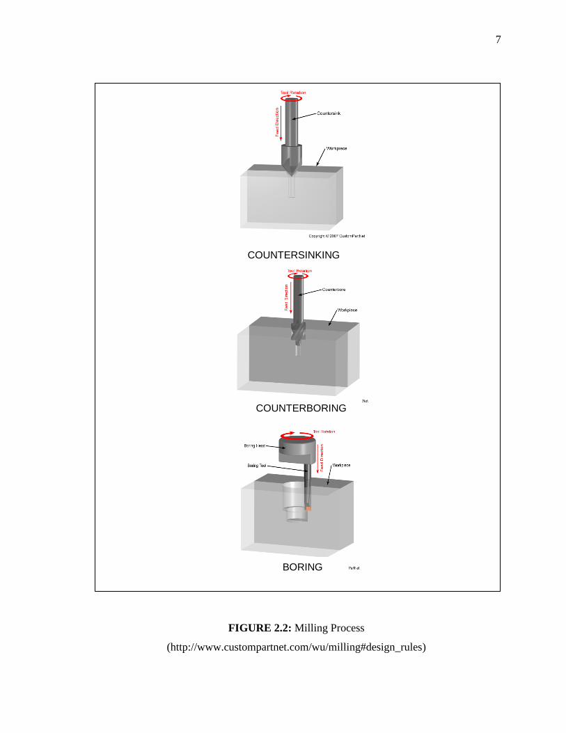
FIGURE 2.2: Milling Process
(http://www.custompartnet.com/wu/milling#design_rules)
COUNTERSINKING
BORING
COUNTERBORING
8
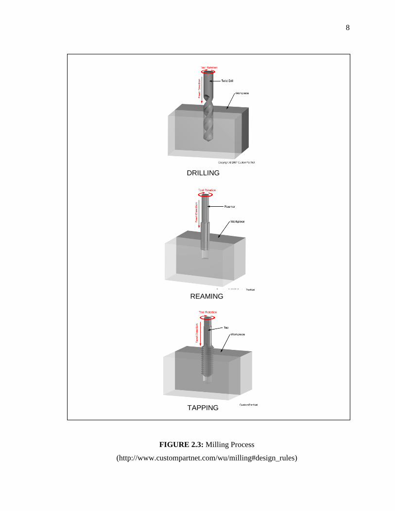
FIGURE 2.3: Milling Process
(http://www.custompartnet.com/wu/milling#design_rules)
DRILLING
REAMING
TAPPING
9
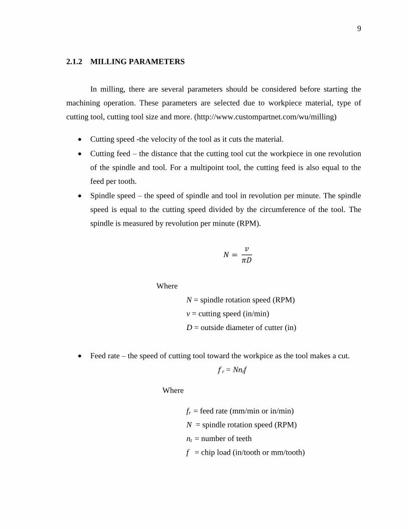
2.1.2 MILLING PARAMETERS
In milling, there are several parameters should be considered before starting the
machining operation. These parameters are selected due to workpiece material, type of
cutting tool, cutting tool size and more. (http://www.custompartnet.com/wu/milling)
Cutting speed -the velocity of the tool as it cuts the material.
Cutting feed – the distance that the cutting tool cut the workpiece in one revolution
of the spindle and tool. For a multipoint tool, the cutting feed is also equal to the
feed per tooth.
Spindle speed – the speed of spindle and tool in revolution per minute. The spindle
speed is equal to the cutting speed divided by the circumference of the tool. The
spindle is measured by revolution per minute (RPM).
Where
N = spindle rotation speed (RPM)
v = cutting speed (in/min)
D = outside diameter of cutter (in)
Feed rate – the speed of cutting tool toward the workpice as the tool makes a cut.
r = Nntf
Where
fr = feed rate (mm/min or in/min)
N = spindle rotation speed (RPM)
nt = number of teeth
f = chip load (in/tooth or mm/tooth)
10
2.2 MILLING CUTTER
Milling cutters are one of the most important elements in milling process. Milling
cutter helps in cutting different materials. Milling cutter is usually made of high speed steel.
2.2.1 End Mill
End mill is a type of milling cutter. Usually, end mill is a cutting tool that is used in
an industrial milling application. It is a sharp milling cutter that will be rotated by the
spindle. The cutter is a cylindrical tool with sharp teeth and there is a space between the
teeth around the exterior. The space between the teeth is called flute and its function to
remove all the chips form during machining from the work piece. Figure 2.2 shows the end
mill nomenclature. The number of flutes that usually used is two and four flute end mill.
The two flute end mill allows maximum space for chip ejection. It is generally used in the
milling machine. Three flute end mill is used for general milling operation and its give
excellent for slotting. End mill with 4, 5, 6, and 8 flutes can be used to improve the surface
roughness if the feed rate remains constant. It is because a greater number of flutes reduces
chip load. The end milling cutter can be categorized by the number of flutes, material, helix
angle, and coating material. It also can be categorized by specific application and special
geometry.
11
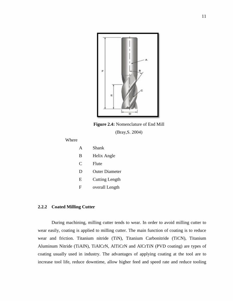
Figure 2.4: Nomenclature of End Mill
(Bray,S. 2004)
Where
A Shank
B Helix Angle
C Flute
D Outer Diameter
E Cutting Length
F overall Length
2.2.2 Coated Milling Cutter
During machining, milling cutter tends to wear. In order to avoid milling cutter to
wear easily, coating is applied to milling cutter. The main function of coating is to reduce
wear and friction. Titanium nitride (TiN), Titanium Carbonitride (TiCN), Titanium
Aluminum Nitride (TiAlN), TiAlCrN, AlTiCrN and AlCrTiN (PVD coating) are types of
coating usually used in industry. The advantages of applying coating at the tool are to
increase tool life, reduce downtime, allow higher feed and speed rate and reduce tooling
12
cost per job. Without correct tool choice, coating choice, the part material, tool rigidity,
machine parameter will reduce the coating advantage as mention above (Park, H.O. 2012).
Titanium nitride (TiN) is produced in gold color. It is used for better tool life during
machining mild steel, stainless steel and lnconel. The surface hardness of TiN is about 80
Rc. TiN has a very good corrosion resistance, heat transmission and excellent wear
resistance. Characteristic of TiN is shown in the table below.
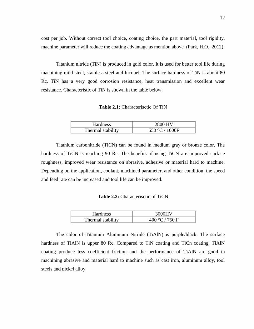
Table 2.1: Characterisctic Of TiN
Hardness 2800 HV
Thermal stability 550 °C / 1000F
Titanium carbonitride (TiCN) can be found in medium gray or bronze color. The
hardness of TiCN is reaching 90 Rc. The benefits of using TiCN are improved surface
roughness, improved wear resistance on abrasive, adhesive or material hard to machine.
Depending on the application, coolant, machined parameter, and other condition, the speed
and feed rate can be increased and tool life can be improved.
Table 2.2: Characterisctic of TiCN
Hardness 3000HV
Thermal stability 400 °C / 750 F
The color of Titanium Aluminum Nitride (TiAlN) is purple/black. The surface
hardness of TiAlN is upper 80 Rc. Compared to TiN coating and TiCn coating, TiAlN
coating produce less coefficient friction and the performance of TiAlN are good in
machining abrasive and material hard to machine such as cast iron, aluminum alloy, tool
steels and nickel alloy.
13
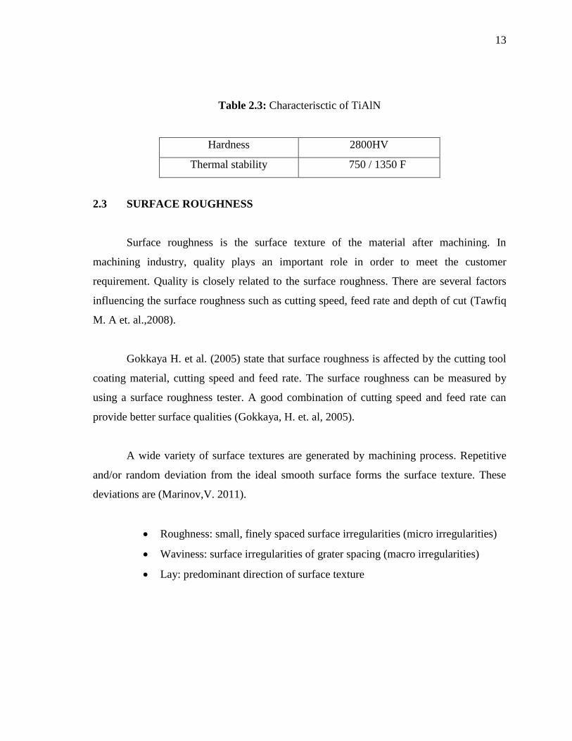
Table 2.3: Characterisctic of TiAlN
Hardness 2800HV
Thermal stability 750 / 1350 F
2.3 SURFACE ROUGHNESS
Surface roughness is the surface texture of the material after machining. In
machining industry, quality plays an important role in order to meet the customer
requirement. Quality is closely related to the surface roughness. There are several factors
influencing the surface roughness such as cutting speed, feed rate and depth of cut (Tawfiq
M. A et. al.,2008).
Gokkaya H. et al. (2005) state that surface roughness is affected by the cutting tool
coating material, cutting speed and feed rate. The surface roughness can be measured by
using a surface roughness tester. A good combination of cutting speed and feed rate can
provide better surface qualities (Gokkaya, H. et. al, 2005).
A wide variety of surface textures are generated by machining process. Repetitive
and/or random deviation from the ideal smooth surface forms the surface texture. These
deviations are (Marinov,V. 2011).
Roughness: small, finely spaced surface irregularities (micro irregularities)
Waviness: surface irregularities of grater spacing (macro irregularities)
Lay: predominant direction of surface texture