effects of impactor and other geometric parameters on...
TRANSCRIPT
25
AMSE JOURNALS –2016-Series: Modelling A; Vol. 89; N° 1 ; pp 25-44
Submitted Nov. 2015; Revised Feb. 18, 2016; Accepted March 15, 2016
Effects of Impactor and other Geometric Parameters
on Impact Behavior of FRP Laminated Composite Plate
Md. Muslim Ansari, Anupam Chakrabarti, M Ashraf Iqbal
Department of Civil Engineering, Indian Institute of Technology,
Roorkee-247 667, India
([email protected]; [email protected]; [email protected])
Abstract
In the present study, behaviour of FRP laminated composite plate subjected to impact by a
spherical steel bullet has been investigated by numerical analysis using finite element
method. The variation of stresses and central transverse deflections with time for different
thickness as well as stacking sequences of composite plates, different sizes and velocities of
impactors have been presented for different boundary conditions. Nature of failure of FRP
composite plate due to low velocity impact has been study in detailed. Effects of stacking
sequences and boundary conditions on damage initiation in the FRP laminated composite
plates based on Hashin’s criterion have been studied. From the numerical analysis it can be
concluded that, the angle ply ( 45 / 45 / 45 ) laminate is more efficient than the cross ply
( 0 / 90 / 0 ) and other angle ply ( 30 / 30 / 30 ) laminates since it exhibits less damage
area and less deflection. Some results obtained from the present FE model are also validated
and discussed with those available in the literature.
Key words
FRP composite, finite element method, Impact load, Damage initiation, GFRP
1. Introduction
FRP composites are versatile materials for the structural application due to their virtues of
light weight, high stiffness, high strength and ease of erection in any environment. Some
composite material like GFRP and Kevlar epoxy are resistive against thermal as well as
chemical attack in most of the cases and hence these materials are widely used in
26
retrofitting and marine structures like deck harbor, ship decks etc. Due to light weight and
high stiffness of FRP composite, these materials are effectively used in the making of
indoor and outdoor swimming pools, external body of racing bikes, roof sheeting and
bridge deck etc.
The analysis of FRP laminated composite plate subjected to impact load has
received widespread attention. Effect of low energy impact on a FRP laminated composite
plate may be quite considerable as internal damage can cause a significant reduction of the
strength of material without any observable damage on the impacted surface [1-3]. Due to
this reason, it attracts many researchers to predict the nature and extent of damage caused
by low energy impact in which penetration of the impactor does no take place and after
impact it rebounds.
Despite of many virtues, these structures show highly complex behavior under
impact and are very sensitive to non-visual damages that strongly influence their residual
load caring capacity. Damage initiation and growth are closely dependent on both impact
source properties. During low energy impact, the time of contact between the impactor and
target material is relatively long. Theoretically, many works had been carried out with an
aim to study the behavior of composite targets under impact load. Chakrabarti et al. [4-5]
studied the delamination behaviour in FRP composite plate by using analytical methods.
Karakuzu et al. [6] studied about the residual stresses in a composite beam under transverse
loading.
Using the composite laminate theory and failure criteria given by Hashin [7], Wang
and Yew [8] analyzed the damage in composite plate under transverse impact load. Sun and
Liou [9] studied the behaviour of laminated composite plate by using a three-dimensional
hybrid stress finite element method in the space domain along with the Newmark direct
integration method. Palazotto et al. [10] analyzed Nomex honey comb sandwich core and
modeling was done using an elastic plastic foundation. Contact loading is simulated by
Hertizian pressure distribution for which contact radius is determined iteratively. Mishra
and Nayak [11] proposed an analytical model for woven fabric composite under impact
with four edges simply supported. Evci and Gülgeç [12] studied the impact damage and
maximum force thresholds in three different types of composites, Unidirectional E-Glass,
woven E-Glass and woven Aramid composite samples under impact load. Bilingardi and
Vadori [13] experimentally analyzed a composite plate under low energy impact with small
dirt. Sabet et al. [14] worked on high velocity impact performance of glass reinforced
polyester (GRP) resin with different types of reinforcements.
27
However, very less numbers of works are reported in the literature highlighting the effect of
impact in describing the damage area and their propagation for laminated composite plates
having different stacking sequence, thickness of plate and boundary conditions. In the
present work, ABAQUS (6.12) finite element software is used to investigate the transient
response of FRP composite plate under impact with different thickness, stacking sequences
of composite plate, different sizes and velocities of impactor to investigate the damage area
in addition to other responses. The finite element model is implemented using Hashin’s
failure model available in ABAQUS to predict damage initiation in FRP composite plate.
The present results are validated with the results available in literature before generating
new results for future reference.
2. Modeling and Simulation
FRP laminated composite plate is modeled with three dimensional elements i.e. 8 nodded
continuum shell (SC8R) to study the dynamic behavior as well as modes of damage under
impact. Analysis is carried out with reduced integration and hourglass controlled condition to
minimize the computational time. Surface-to-surface contact interaction is used describe the
contact between deformable surface and a rigid surface. Therefore, surface to surface contact
with zero friction is assigned for the interaction between bullet and composite plate under explicit
condition. Damage initiation refers to the onset of degradation at a material point. The damage
initiation criteria for fiber reinforced composite plate are based on Hashin’s theory. Four different
modes of failure initiation criteria given by Hashin (1980) are described as follows:
Fiber tension initiation criteria (HSNFTCRT)
Fiber compression initiation criteria (HSNFCCRT)
Matrix tension initiation criteria (HSNMTCRT) and
Matrix compression initiation criteria (HSNMCCRT)
Expression of Hashin’s initiation criteria as follows
Fiber tension 11 0
22
11 12tf LTF
SX
(2.1)
Fiber compression 11 0
2
11Cf CF
X
(2.2)

28
Matrix tension 22 0
22
22 12tm LTF
SY
(2.3)
Matrix compression 22 0
22 2C22 22 12
T T LC1
2 2
Cm
YF
S S SY
(2.4)
WheretfF ,
CfF are failure index for fiber in tension and compression, respectively;
tmF ,
CmF are
failure index for matrix in tension and compression, respectively; TX , C
X are tensile and
compressive strength in fiber direction; CY is compressive strength perpendicular to fiber
direction,L
S ,T
S = longitudinal and transverse shear strength. A value of 1.0 or higher for failure
indices indicate that the initiation criterion has been met and elements in composite starts to fail.
3. Results and Discussions
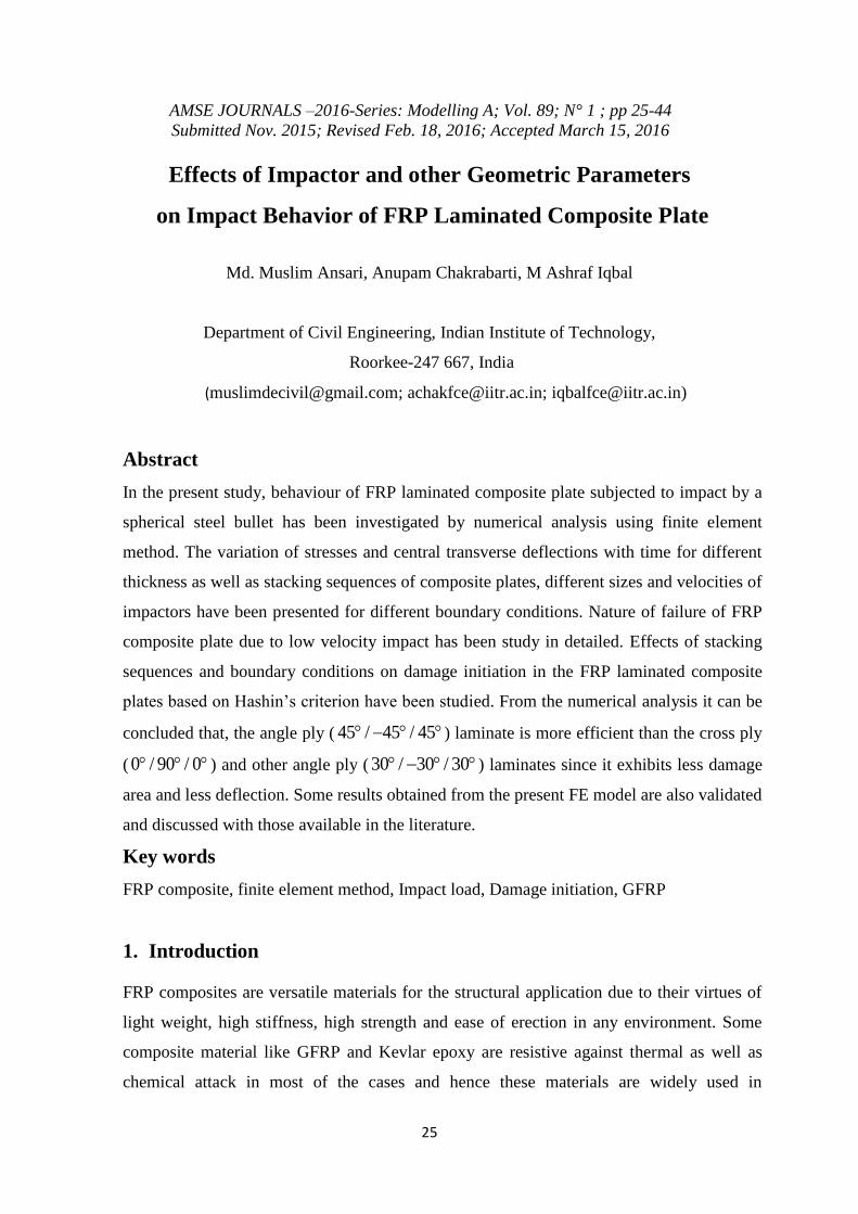
3.1. Convergence verification
Mesh convergence study of numerical model is required to identify the optimum mesh division
which meets more accurate and mesh independent results. In the present work, mesh division of
72 x 72 along x-y plane has been taken which shows convergence in the result as in Fig. 1.
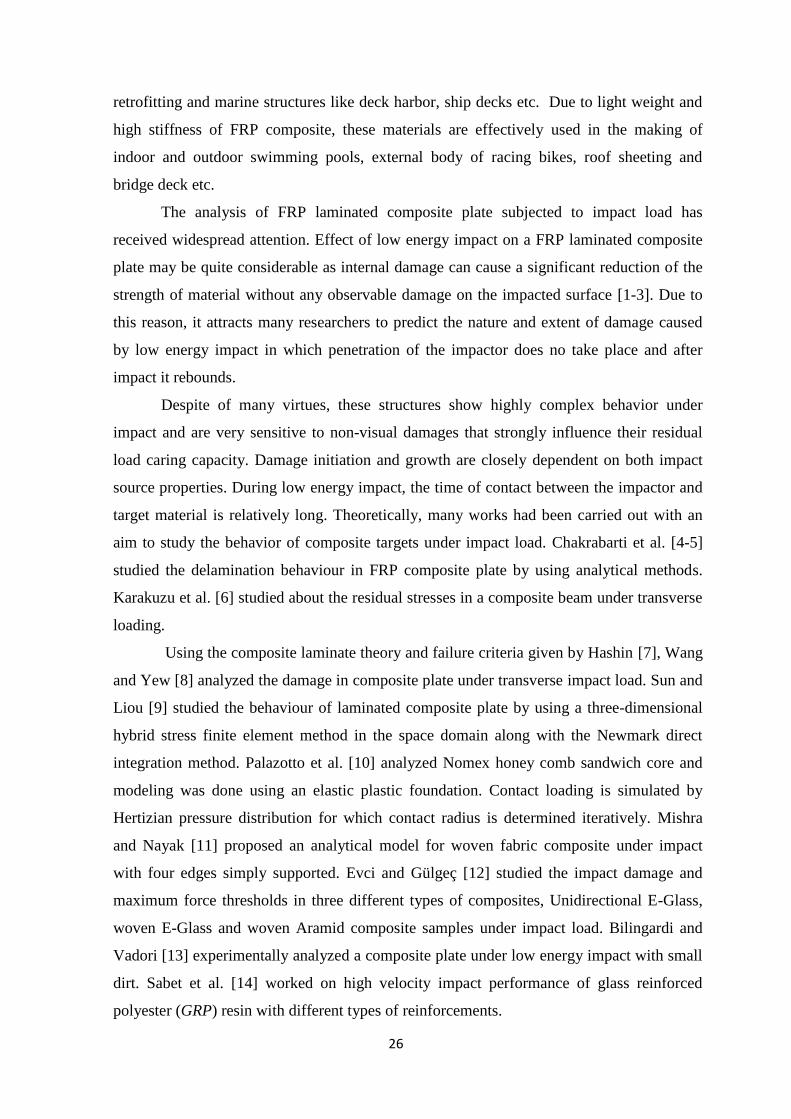
Square plate of dimension 140 mm × 140 mm with three layers of equal thickness and impactor
as a rigid body of diameter 10 mm and mass 0.014175 kg are considered in this work as shown in
Fig. 2. The material properties of composite plate made of graphite-epoxy AS-3501-6 are: E11=
142.73 GPa, E22 = 13.79 GPa, G12= G13= 4.64 GPa, G23 = 4.14
GPa, 12 13 0.3 , 23 0.28
29
Mesh devision
8x8 16x16 32x32 64x64 72x72 128x128
Ce
ntr
al d
efle
ctio
n (
mm
)
1.31
1.32
1.33
1.34
1.35
1.36
Col 1 vs Col 2
Fig. 1. Variation of central deflection with mesh division
Fig. 2. Composite plate coordinate system and ply stacking of cross ply ( 0 / 90 / 0 ) laminate
3.2. Numerical results and discussions
This section presents the response of FRP composite plate under impact with different sizes of
impactors (radius: 5 mm and 7.5 mm) and initial velocities of impactors on different thickness
and stacking sequences of composite plate under different boundary conditions. Deflection of
cross ply ( 0 / 90 / 0 ) laminated plate at contact point due to impact by 0.014175 kg impactor
with incidence velocity 22.6 m/s has been shown in Fig. 3 and compared with available literature
as mentioned there. Time of separation of impactor from the plate is approximately 210 s in
30
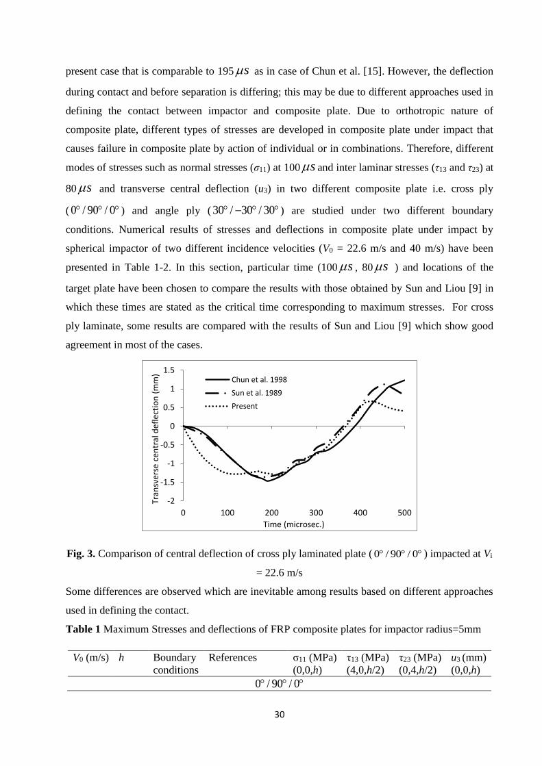
present case that is comparable to 195 s as in case of Chun et al. [15]. However, the deflection
during contact and before separation is differing; this may be due to different approaches used in
defining the contact between impactor and composite plate. Due to orthotropic nature of
composite plate, different types of stresses are developed in composite plate under impact that
causes failure in composite plate by action of individual or in combinations. Therefore, different
modes of stresses such as normal stresses (σ11) at 100 s and inter laminar stresses (τ13 and τ23) at
80 s and transverse central deflection (u3) in two different composite plate i.e. cross ply
( 0 / 90 / 0 ) and angle ply ( 30 / 30 / 30 ) are studied under two different boundary
conditions. Numerical results of stresses and deflections in composite plate under impact by
spherical impactor of two different incidence velocities (V0 = 22.6 m/s and 40 m/s) have been
presented in Table 1-2. In this section, particular time (100 s , 80 s ) and locations of the
target plate have been chosen to compare the results with those obtained by Sun and Liou [9] in
which these times are stated as the critical time corresponding to maximum stresses. For cross
ply laminate, some results are compared with the results of Sun and Liou [9] which show good
agreement in most of the cases.
-2
-1.5
-1
-0.5
0
0.5
1
1.5
0 100 200 300 400 500
Tran
sver
se c
entr
al d
efle
ctio
n (
mm
)
Time (microsec.)
Chun et al. 1998
Sun et al. 1989
Present
Fig. 3. Comparison of central deflection of cross ply laminated plate ( 0 / 90 / 0 ) impacted at Vi
= 22.6 m/s
Some differences are observed which are inevitable among results based on different approaches
used in defining the contact.
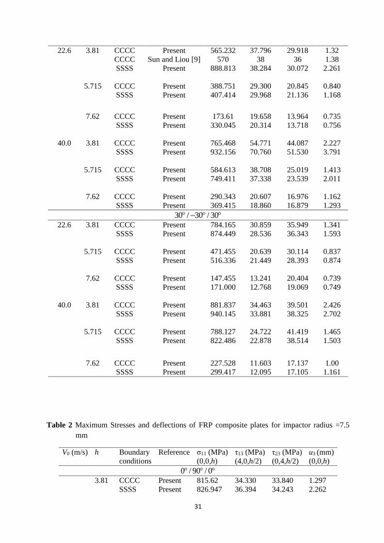
Table 1 Maximum Stresses and deflections of FRP composite plates for impactor radius=5mm
V0 (m/s) h Boundary
conditions
References σ11 (MPa)
(0,0,h)
τ13 (MPa)
(4,0,h/2)
τ23 (MPa)
(0,4,h/2)
u3 (mm)
(0,0,h)
0 / 90 / 0
31
22.6
3.81 CCCC Present 565.232 37.796 29.918 1.32
CCCC Sun and Liou [9] 570 38 36 1.38
SSSS Present 888.813 38.284 30.072 2.261
5.715 CCCC Present 388.751 29.300 20.845 0.840
SSSS Present 407.414 29.968 21.136 1.168
7.62 CCCC Present 173.61 19.658 13.964 0.735
SSSS Present 330.045 20.314 13.718 0.756
40.0
3.81 CCCC Present 765.468 54.771 44.087 2.227
SSSS Present 932.156 70.760 51.530 3.791
5.715 CCCC Present 584.613 38.708 25.019 1.413
SSSS Present 749.411 37.338 23.539 2.011
7.62 CCCC Present 290.343 20.607 16.976 1.162
SSSS Present 369.415 18.860 16.879 1.293
30 / 30 / 30
22.6
3.81 CCCC Present 784.165 30.859 35.949 1.341
SSSS Present 874.449 28.536 36.343 1.593
5.715 CCCC Present 471.455 20.639 30.114 0.837
SSSS Present 516.336 21.449 28.393 0.874
7.62 CCCC Present 147.455 13.241 20.404 0.739
SSSS Present 171.000 12.768 19.069 0.749
40.0
3.81 CCCC Present 881.837 34.463 39.501 2.426
SSSS Present 940.145 33.881 38.325 2.702
5.715 CCCC Present 788.127 24.722 41.419 1.465
SSSS Present 822.486 22.878 38.514 1.503
7.62 CCCC Present 227.528 11.603 17.137 1.00
SSSS Present 299.417 12.095 17.105 1.161
Table 2 Maximum Stresses and deflections of FRP composite plates for impactor radius =7.5
mm
V0 (m/s) h Boundary
conditions
Reference σ11 (MPa)
(0,0,h)
τ13 (MPa)
(4,0,h/2)
τ23 (MPa)
(0,4,h/2)
u3 (mm)
(0,0,h)
0 / 90 / 0
3.81 CCCC Present 815.62 34.330 33.840 1.297
SSSS Present 826.947 36.394 34.243 2.262
32
22.6
5.715 CCCC Present 271.980 21.404 14.716 0.767
SSSS Present 291.338 21.256 9.609 1.148
7.62 CCCC Present 53.111 12.007 5.858 0.678
SSSS Present 74.083 12.218 8.263 0.739
40.0
3.81 CCCC Present 1230.49 60.848 62.6927 2.137
SSSS Present 1340.44 60.160 61.371 3.805
5.715 CCCC Present 450.811 27.4432 19.810 1.280
SSSS Present 481.561 28.100 20.400 1.970
7.62 CCCC Present 45.496 9.628 6.422 1.061
SSSS Present 65.112 9.676 6.729 1.274
30 / 30 / 30
22.6
3.81 CCCC Present 845.910 23.974 34.844 1.174
SSSS Present 860.632 25.334 32.450 1.539
5.715 CCCC Present 317.767 14.581 20.908 0.788
SSSS Present 324.561 15.309 20.678 0.861
7.62 CCCC Present 57.489 7.846 11.952 0.670
SSSS Present 87.187 7.912 11.729 0.672
40.0
3.81 CCCC Present 1220.11 30.7139 54.939 2.204
SSSS Present 1248.21 30.353 55.179 2.623
5.715 CCCC Present 346.005 16.356 23.133 1.268
SSSS Present 368.079 16.551 23.927 1.274
7.62 CCCC Present 88.766 6.281 8.890 1.060
SSSS Present 94.963 7.738 9.609 1.069
3.2.1. Deflection
Maximum central transverse deflections of 140 mm × 140 mm square composite plate due to
impact by spherical impactor of different sizes and incidence velocities under different thickness,
stacking sequences and boundary conditions have been presented in Table 1-2. It is observed that
the deflection is more in the case of simply supported plate than the plate having fully clamped
condition for both cross ply and angle ply laminates. Deflection in composite plate decreases as
the size of impactor increases for different incidence velocities and thicknesses under both
boundary conditions. For fully clamped cross ply laminate deflection decreases by 2.11% for
impactor size increases by 1.5 times with incidence velocity of 22.6 m/s and plate thickness h =
3.81 mm.
33
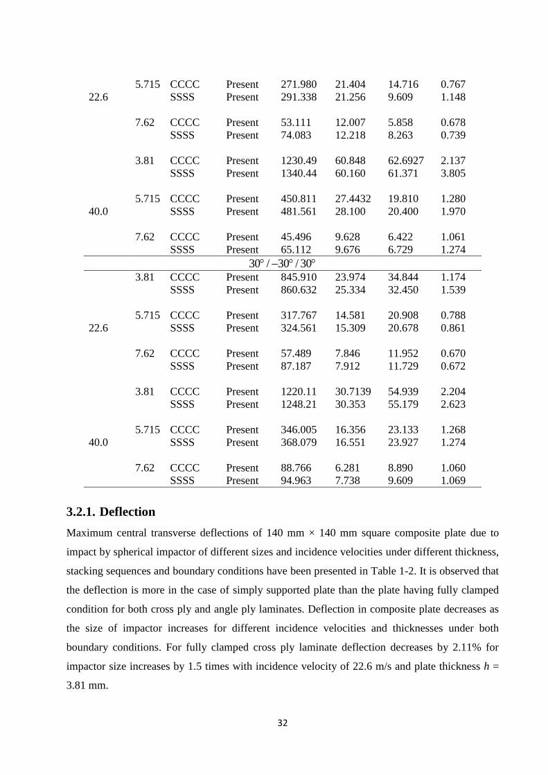
To study the effect of ply thickness on the behavior of composite plate, a cross ply
laminate with 3, 4 and 5 plies is impacted by a spherical bullet with incidence velocity of 22.6
m/s.
Transverse central deflection at impact point has been plotted for all the three laminate as shown
in Fig. 4. Central transverse deflection is showing little bit difference in their peak values but
the same trend of variation is observed. However, 4 layered cross ply laminate shows more
deflection as compared to others and possibility of this difference is due to its unsymmetrical
nature. For symmetric laminates, central deflection and the nature of vibration are more in the
case of 5 layered laminate than 3 layered laminate.
0 200 400 600 800 1000
Cen
tra
l defle
ction (
mm
)
-1.5
-1.0
-0.5
0.0
0.5
1.0
1.5
0/90/0
0/90/0/90
0/90/0/90/0
Time (microsec.)
Fig. 4. Central transverse deflections for 3, 4 and 5 layered cross ply laminate
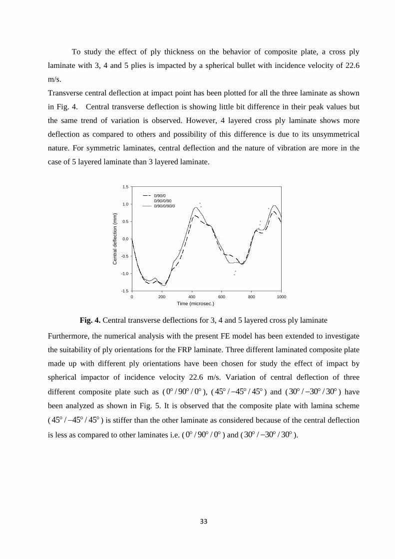
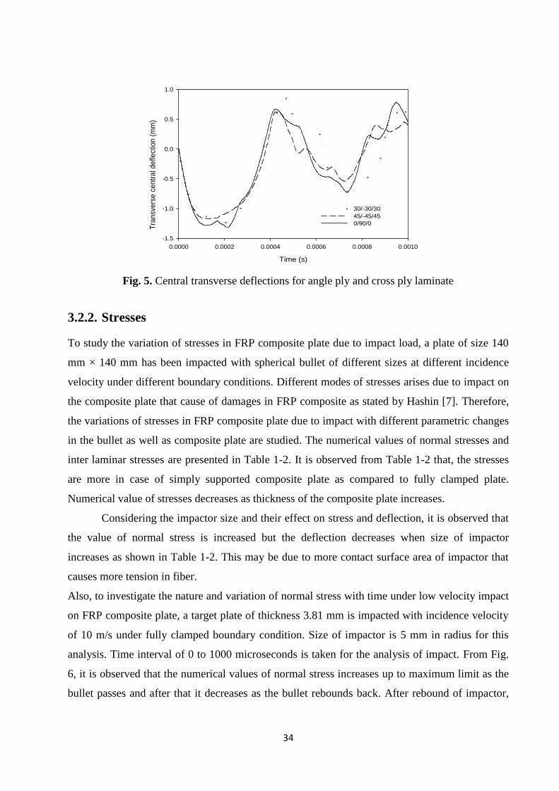
Furthermore, the numerical analysis with the present FE model has been extended to investigate
the suitability of ply orientations for the FRP laminate. Three different laminated composite plate
made up with different ply orientations have been chosen for study the effect of impact by
spherical impactor of incidence velocity 22.6 m/s. Variation of central deflection of three
different composite plate such as ( 0 / 90 / 0 ), ( 45 / 45 / 45 ) and (30 / 30 / 30 ) have
been analyzed as shown in Fig. 5. It is observed that the composite plate with lamina scheme
( 45 / 45 / 45 ) is stiffer than the other laminate as considered because of the central deflection
is less as compared to other laminates i.e. ( 0 / 90 / 0 ) and (30 / 30 / 30 ).
34
Time (s)
0.0000 0.0002 0.0004 0.0006 0.0008 0.0010
Tra
nsv
ers
e c
en
tra
l de
flect
ion
(m
m)
-1.5
-1.0
-0.5
0.0
0.5
1.0
30/-30/30
45/-45/45
0/90/0
Fig. 5. Central transverse deflections for angle ply and cross ply laminate
3.2.2. Stresses
To study the variation of stresses in FRP composite plate due to impact load, a plate of size 140
mm × 140 mm has been impacted with spherical bullet of different sizes at different incidence
velocity under different boundary conditions. Different modes of stresses arises due to impact on
the composite plate that cause of damages in FRP composite as stated by Hashin [7]. Therefore,
the variations of stresses in FRP composite plate due to impact with different parametric changes
in the bullet as well as composite plate are studied. The numerical values of normal stresses and
inter laminar stresses are presented in Table 1-2. It is observed from Table 1-2 that, the stresses
are more in case of simply supported composite plate as compared to fully clamped plate.
Numerical value of stresses decreases as thickness of the composite plate increases.
Considering the impactor size and their effect on stress and deflection, it is observed that
the value of normal stress is increased but the deflection decreases when size of impactor
increases as shown in Table 1-2. This may be due to more contact surface area of impactor that
causes more tension in fiber.
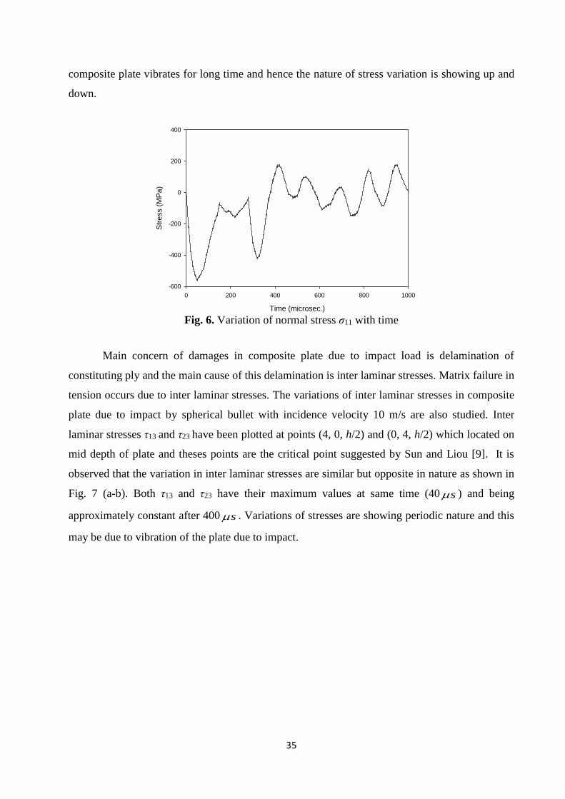
Also, to investigate the nature and variation of normal stress with time under low velocity impact
on FRP composite plate, a target plate of thickness 3.81 mm is impacted with incidence velocity
of 10 m/s under fully clamped boundary condition. Size of impactor is 5 mm in radius for this
analysis. Time interval of 0 to 1000 microseconds is taken for the analysis of impact. From Fig.
6, it is observed that the numerical values of normal stress increases up to maximum limit as the
bullet passes and after that it decreases as the bullet rebounds back. After rebound of impactor,
35
composite plate vibrates for long time and hence the nature of stress variation is showing up and
down.
Time (microsec.)
0 200 400 600 800 1000
Str
ess (
MP
a)
-600
-400
-200
0
200
400
Fig. 6. Variation of normal stress σ11 with time
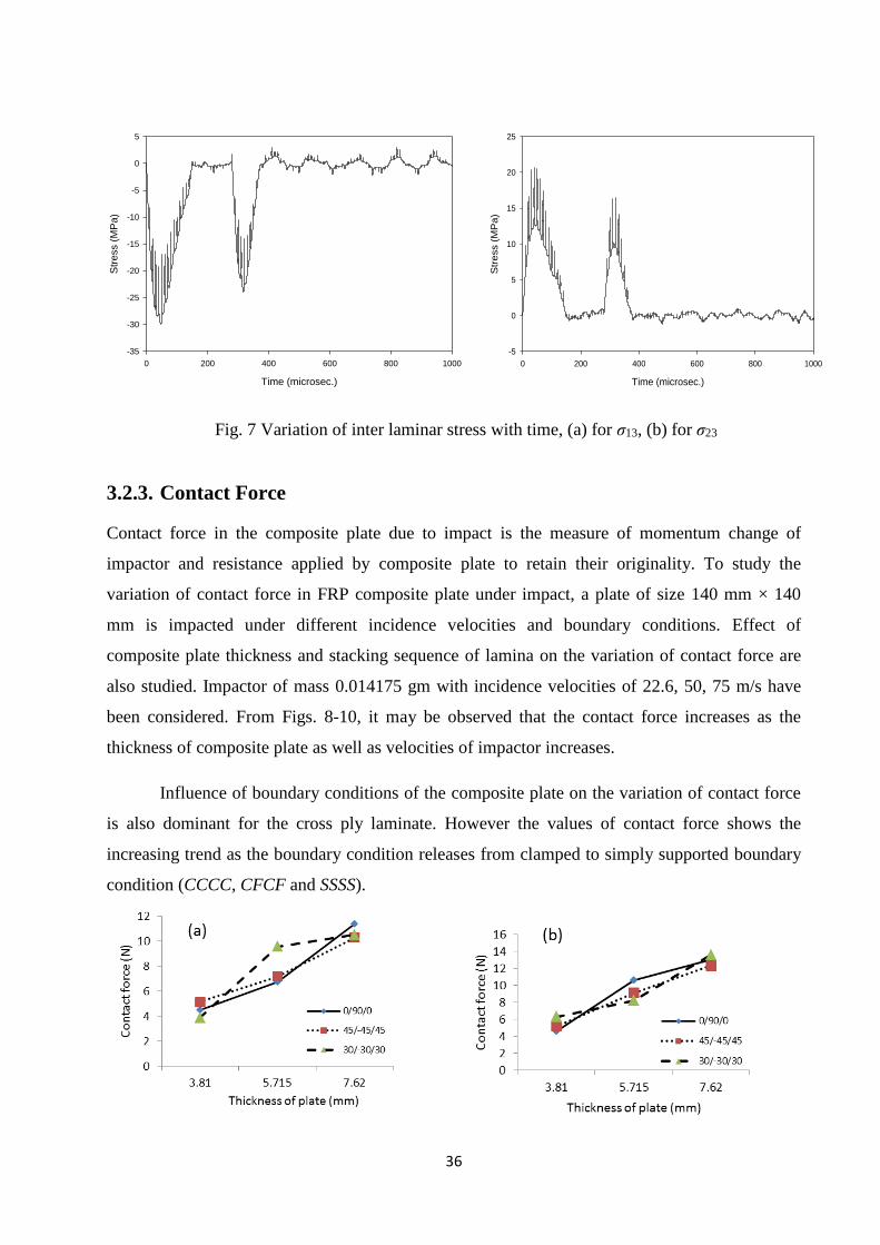
Main concern of damages in composite plate due to impact load is delamination of
constituting ply and the main cause of this delamination is inter laminar stresses. Matrix failure in
tension occurs due to inter laminar stresses. The variations of inter laminar stresses in composite
plate due to impact by spherical bullet with incidence velocity 10 m/s are also studied. Inter
laminar stresses τ13 and τ23 have been plotted at points (4, 0, h/2) and (0, 4, h/2) which located on
mid depth of plate and theses points are the critical point suggested by Sun and Liou [9]. It is
observed that the variation in inter laminar stresses are similar but opposite in nature as shown in
Fig. 7 (a-b). Both τ13 and τ23 have their maximum values at same time (40 s ) and being
approximately constant after 400 s . Variations of stresses are showing periodic nature and this
may be due to vibration of the plate due to impact.
36
Time (microsec.)
0 200 400 600 800 1000
Str
ess (
MP
a)
-35
-30
-25
-20
-15
-10
-5
0
5
Time (microsec.)
0 200 400 600 800 1000
Str
ess (
MP
a)
-5
0
5
10
15
20
25
Fig. 7 Variation of inter laminar stress with time, (a) for σ13, (b) for σ23
3.2.3. Contact Force
Contact force in the composite plate due to impact is the measure of momentum change of
impactor and resistance applied by composite plate to retain their originality. To study the
variation of contact force in FRP composite plate under impact, a plate of size 140 mm × 140
mm is impacted under different incidence velocities and boundary conditions. Effect of
composite plate thickness and stacking sequence of lamina on the variation of contact force are
also studied. Impactor of mass 0.014175 gm with incidence velocities of 22.6, 50, 75 m/s have
been considered. From Figs. 8-10, it may be observed that the contact force increases as the
thickness of composite plate as well as velocities of impactor increases.
Influence of boundary conditions of the composite plate on the variation of contact force
is also dominant for the cross ply laminate. However the values of contact force shows the
increasing trend as the boundary condition releases from clamped to simply supported boundary
condition (CCCC, CFCF and SSSS).
37
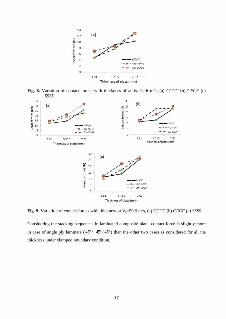
Fig. 8. Variation of contact forces with thickness of at V0=22.6 m/s, (a) CCCC (b) CFCF (c)
SSSS
Fig. 9. Variation of contact forces with thickness at V0=50.0 m/s, (a) CCCC (b) CFCF (c) SSSS
Considering the stacking sequences in laminated composite plate, contact force is slightly more
in case of angle ply laminate ( 45 / 45 / 45 ) than the other two cases as considered for all the
thickness under clamped boundary condition.

38
Fig. 10 Variation of contact forces with thickness of plate at V0=75.0 m/s, (a) CCCC (b) CFCF
(c) SSSS
3.3. Damage initiation
FRP composite plate of size 140 mm × 140 mm × 3.81 mm with material properties given in
Table 3 and spherical bullet of diameter 10 mm and mass 0.014175 kg have been modeled to
study the damage initiation in composite plate due to impact. In this analysis, Hashin’s criteria is
incorporated in material model to remove the elements those meet the criteria of failure. Element
in the composite plate that meet the criteria of damage initiation then it assumed that the
contribution of that element in the stiffness matrix calculation is zero. Indeed there is no
complete penetration of the FRP composite plate by impactor.
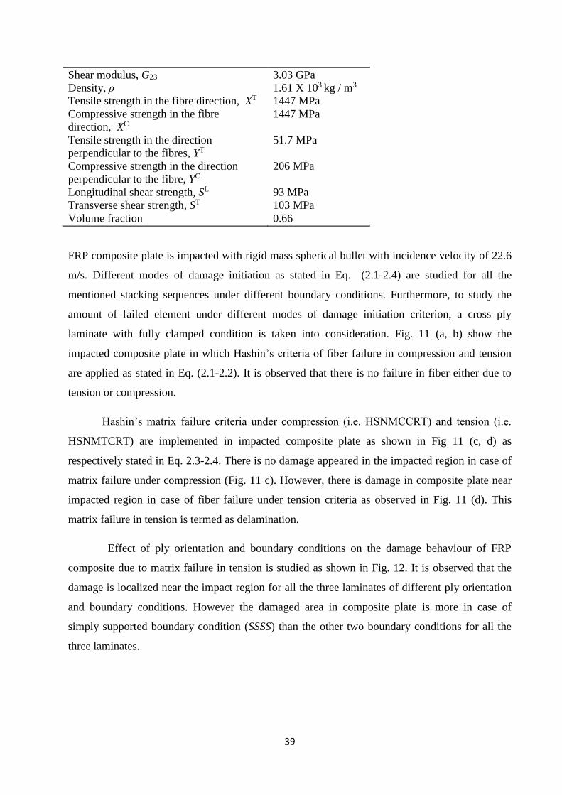
Table 3: Material properties of graphite-epoxy AS-3501-6
Young modulus at fibre direction, E11 142.73 GPa
Young modulus at normal to the fibre, E22 13.79 GPa
Poisson’s ratio, υ12 0.3
Shear modulus, G12 4.64 GPa
Shear modulus, G13 4.64 GPa
39
Shear modulus, G23 3.03 GPa
Density, ρ 1.61 X 10³ kg / m3
Tensile strength in the fibre direction, XT 1447 MPa
Compressive strength in the fibre
direction, XC
1447 MPa
Tensile strength in the direction
perpendicular to the fibres, YT
51.7 MPa
Compressive strength in the direction
perpendicular to the fibre, YC
206 MPa
Longitudinal shear strength, SL 93 MPa
Transverse shear strength, ST 103 MPa
Volume fraction 0.66
FRP composite plate is impacted with rigid mass spherical bullet with incidence velocity of 22.6
m/s. Different modes of damage initiation as stated in Eq. (2.1-2.4) are studied for all the
mentioned stacking sequences under different boundary conditions. Furthermore, to study the
amount of failed element under different modes of damage initiation criterion, a cross ply
laminate with fully clamped condition is taken into consideration. Fig. 11 (a, b) show the
impacted composite plate in which Hashin’s criteria of fiber failure in compression and tension
are applied as stated in Eq. (2.1-2.2). It is observed that there is no failure in fiber either due to
tension or compression.
Hashin’s matrix failure criteria under compression (i.e. HSNMCCRT) and tension (i.e.
HSNMTCRT) are implemented in impacted composite plate as shown in Fig 11 (c, d) as
respectively stated in Eq. 2.3-2.4. There is no damage appeared in the impacted region in case of
matrix failure under compression (Fig. 11 c). However, there is damage in composite plate near
impacted region in case of fiber failure under tension criteria as observed in Fig. 11 (d). This
matrix failure in tension is termed as delamination.
Effect of ply orientation and boundary conditions on the damage behaviour of FRP
composite due to matrix failure in tension is studied as shown in Fig. 12. It is observed that the
damage is localized near the impact region for all the three laminates of different ply orientation
and boundary conditions. However the damaged area in composite plate is more in case of
simply supported boundary condition (SSSS) than the other two boundary conditions for all the
three laminates.

40
Fig. 11. Failure of elements due to different failure initiation criteria; (a) failure of fibre under
compression, (b) failure of fibre under tension, (c) failure of matrix under compression, (d)
failure of matrix under compression
Effect of boundary conditions on the damage area in composite plate is more in case cross
ply laminate as observed from Fig. 12 (c). Damaged area in composite plate having simply
supported condition is more as compared CCCC and CFCF boundary conditions for all the
laminate as considered. In spite of major damage near impact region, there is crack propagation
in plate having SSSS boundary condition. Damage starts from impact point termed as major
damage and propagated along the fiber direction as observed from Fig. 12 (a-i).
In the extension of this study, the amount of damaged area in FRP composite plate of different
thickness, stacking sequences and boundary conditions have been studied under impact.
CCCC CFCF SSSS
0 / 90 / 0
(a)
(d) (c)
(b)

41
30 / 30 / 30
45 / 45 / 45
Fig. 12. Damage evolution due to delamination (i.e. HSNMTCRT failure modes)
It is observed that the amount of damaged area in case of angle ply laminate ( 45 / 45 / 45 ) is
less as compared to cross ply ( 0 / 90 / 0 ) and other angle ply ( 30 / 30 / 30 ) laminates in all
the three different boundary conditions as shown in Fig. 13. It may also be observed that the
damaged area is less in case of fully clamped composite plate as compared to simply supported
one for all the three different laminates as considered.
Damage orientation Major damage Cracks
(a)
(e) (d) (f)
(c) (b)
(i) (h) (g)

42
Fig. 13. Variation of damaged area with thickness of plate at V0=22.6 m/s, (a) CCCC (b) CFCF
(c)
Nomenclature
The following nomenclature is used throughout the paper, otherwise stated locally in the text.
CCCC – all four edges clamped
CFCF – two edges clamped and two edges free
SSSS – all edges simply supported
h – thickness of plate
h/a – ratio of thickness to side of plate
11 13 23, , – stresses in plate in respective directions
3u – transverse deflection perpendicular to the plate
0V – initial velocity of impactor
4. Conclusions
Laminated FRP composite plate subjected to transverse impact load has been analyzed with finite
element model under different parametric variation of impactor as well as composite plate. The
damaged areas, central deflections, normal stress and inter laminar stresses in FRP composite
with different thickness, stacking sequences of lamina, different sizes and velocities of impactor

43
under different boundary conditions are presented. Nature of failure and its behavior in FRP
composite plate have been discussed for different types of laminates and boundary conditions.
On the basis of this analysis some important observations are stated below;
It may be concluded that the damage initiation and propagation in the composite plate
with fully clamped boundary condition is lesser as compared to lesser restrained plate.
Damage in the composite plate due to low velocity impact is mainly due to matrix
cracking in tension or delamination.
Among the three laminate scheme as considered, angle ply laminate ( 45 / 45 / 45 ) is
stiffer against the deflection and damage than the cross ply ( 0 / 90 / 0 ) and other angle
ply ( 30 / 30 / 30 ) laminates.
In some cases present results are compared with published results which show close
agreement.
References
[1] R. Tiberkak, M. Bachene, S. Rechak and B. Necib, “Damage prediction in composite
plates subjected to low velocity impact” Composite structures, vol. 83, pp. 73-82, 2008.
[2] Z. Aslan, R. Karakuza and B. Okutan, “The response of laminated composite plates under
low velocity impact loading”, Composite structures, vol. 59, pp. 119-127, 2003.
[3] C. F. Li, N. Hu and Y. G. Chen, “Fukunaga H, Sekine H. Low velocity impact induced
damage of continuous fiber-reinforced composite laminates. Verification and numerical
investigation”, Composites Part A, vol. 33, pp. 1063-1072, 2002.
[4] A. Chakrabarti, P. K. Gupta, S. Chakraborti and K. G. Babu, “Modelling of delamination
in fiber reinforced plastic (FRP) laminated composites: I”, AMSE Journals, Modelling A,
Vol. 82-4, pp. 50-67, 2009.
[5] A. Chakrabarti, P. K. Gupta, K. G. Babu and S. Chakraborti, “Modelling of delamination
in fiber reinforced plastic (FRP) laminated composites: II”, AMSE Journals, Modelling B,
Vol. 78-2, pp. 47-63, 2009.
[6] Karakuzu and Ramasan, “Analytical solution of residual stresses in Aluminum matrix-
steel fiber composite beam subjected to transverse uniform distribution load”, AMSE
Journals, Modelling B, Vol. 69, pp. 1-12, 2000.

44
[7] Z. Hashin, “Failure criteria for unidirectional fiber composites” Journal of Applied
Mechanics, vol. 47, pp. 329-334, 1980.
[8] C. Y. Wang and C. H. Yew, “Impact damage in composite laminates”, Composite
Structures, vol. 37, pp. 967-982, 1990.
[9] C. T. Sun and W. J. Liou, “Investigation of laminated composite plates under impact
dynamic loading using a three-dimensional hybrid stress finite element method”,
Computers and structures, vol. 33, pp. 879-884, 1989.
[10] A. N. Palazotto, E. J. Herup and L.N.B. Gummadi, “Finite element analysis of low-
velocity impact on composite sandwich plates”, Composite structures, vol. 49, pp. 209–
227, 2000.
[11] A. Mishra and N. K. Naik, “Failure initiation in composite structures under low-velocity
impacts analytical studies”, Composite Structures, vol. 92, no. (2), pp. 436–444, 2010.
[12] C. Evci and M. Gülgeç, “An experimental investigation on the impact response of
composite materials”, International Journal of Impact Engineering, vol. 43, pp. 40–51,
2012.
[13] G. Bilingardi and R. Vadori, “Influence of the laminate thickness in low velocity impact
behavior of composite material plate”, Composite structures, vol. 61, pp. 27–38, 2003.
[14] A. Sabet, N. Fagih and M. H. Beheshty, “Effect of reinforcement type on high velocity
impact response of GRP plates using a sharp tip projectile”, International Journal of
Impact Engineering, vol. 38, pp. 715-722, 2011.
[15] L.U. Chun and K. Y. Lam,” Dynamic response of fully-clamped laminated composite
plates subjected to low-velocity impact of a mass”, International. Journal of solid
structures, vol. 35, pp. 963-979, 1998.
[16] ABAQUS 6.7 User’s Manual, Dassault Systems Simulia Corp. USA, 2007.