effects of the tool path strategies on incremental sheet
TRANSCRIPT
Mechanics & Industry 17, 411 (2016)c© AFM, EDP Sciences 2016DOI: 10.1051/meca/2015094www.mechanics-industry.org
Mechanics&Industry
Effects of the tool path strategies on incremental sheet metalforming process
L. Ben Said, J. Mars, M. Walia and F. Dammak
Mechanical Modelisation and Manufacturing Laboratory (LA2MP), National Engineering School of Sfax,B.P W3038, Sfax, University of Sfax, Tunisia
Received 19 March 2015, Accepted 13 October 2015
Abstract – This paper presents a numerical simulation of the incremental sheet metal forming (ISF)process, type single point incremental forming (SPIF). A finite element model (FEM) is developed by usingthe commercial FE code ABAQUS. An elasto-plastic constitutive model with quadratic yield criterion ofHill’48 and isotropic hardening behavior has been adopted during ISF operation. A user material subroutine(VUMAT) is used to implement this material behavior. Four strategies of tool path during the ISF of apiece having a square box final shape are presented. Results including thickness variation of sheet metal,forming force along Z-axis and the Hill’48 stress distribution for the four strategies are presented andcompared at the aim to optimize the SPIF and to see which tool path strategy makes this process moreeffective with the consideration of the characteristics of specimen manufactured and its material properties.
Key words: Incremental sheet forming / numerical simulation / tool path strategy
1 Introduction
Incremental sheet forming (ISF) is an innovative pro-cess to manufacture sheet metal with numeric incrementson CNC machines through plastic deformation. This pro-cess is relatively slow, allows the manufacture of proto-type parts with complex shapes and high precisions. TwoISF types can be distinguished: the single point incre-mental forming (SPIF) and the two points incrementalforming (TPIF).
The experiences realized with the ISF process are con-centrated in the SPIF process using a CNC machine witha forming tool with specific shape. This tool replaces themilling tool and it uses the same mounting elements in CNmachine. Many trajectories are used in incremental form-ing with numerical increments by the use of CN programin 3 axis or 5 axis machines. The incremental forming tooltrajectories are specific to this process and materials ofsheets manufactured in ISF.
The literature on the subject of ISF: the integrity ofsurfaces during and after the incremental forming, the ge-ometry of the specimen manufactured, forming efforts andoptimization of forming time are investigated by the ma-jority of researches. The majority of manufactured parts,mentioned in the articles, are not industrial parts butthey are test pieces with cone or pyramidal shape where
a Corresponding author: [email protected]
a hemispherical punch is used in the sheet forming pro-cess, with a manner close to the operation of a pocket ina CN milling process. So the study of an industrial piecewill be significant with good experiment results.
Some studies have been proposed to understand theISF process by considering different material behaviorand various tool paths. Robert et al. [1] presented theimplementation of a new algorithm to simulate elasto-plastic material behavior with anisotropic plasticity cri-terion based on the incremental deformation theory inthe ABAQUS commercial finite element code. The algo-rithm is tested for two sheet forming processes: stretchforming, and incremental sheet forming. The aim of thealgorithm is to reduce the global CPU time, to analyzethe stress state and thickness distribution of the studiedsheet metal.
In terms of tool paths, several studies are focused onthe development and the optimization of the tool pathstrategies in ISF process. Concerning tool path genera-tion algorithms, Lu et al. [2] presented a new feature-based tool path generation algorithm for incrementalsheet forming process. In this study, to obtain a betterunderstanding of forming mechanism using the tool pathgeneration method, the thickness distribution, geometricaccuracy and surface quality of the ISF formed shapesare compared with the traditional ISF tool path methodbased on three case studies including a truncated conewith double bottoms, a non-symmetrical cone and a car
Article published by EDP Sciences
L. Ben Said et al.: Mechanics & Industry 17, 411 (2016)
fender. This contribution is based on a conclusion that theconventional contour based strategies have been proven tocause problems in surface quality and geometric accuracyin specimens manufactured by ISF process. Azaouzi andLebaal [3] showed an optimization procedure tested for agiven forming strategy, in order to reduce the manufac-turing time and homogenize thickness distribution of anasymmetric part. The forming strategy was determinedby finite element analyses in combination with responsesurface method and sequential quadratic programming al-gorithm. With their forming strategy they proved thatthere are contradictory relations between optimal timeand homogeneous thickness distribution. Because of con-flicting relations between the criteria of sheet metal form-ing and the solutions that minimize the objective functionwhile preventing that the part thinning does increase andat the same time respecting the part geometry and min-imizing the sheet thickness variability. Belchior et al. [4]developed an approach applied in robotized ISF process,this approach consists in coupling a finite element analy-sis of the ISF (using to predict efforts in this process) withan elastic model of a robot structure where the punch ismounted. The result of finite element simulation was usedlike input data for the elastic model at the aim to opti-mize the punch path and to make correction in robotizedISF when the punch makes deviation. The effect of thehardening law (Ludwick or Voce) has been evaluated.
The prototyping of complex sheet metal parts usingsingle point incremental forming (SPIF) requires the gen-eration of optimal tool paths and/or tool path sequencesthat ensure that the formed part is within geometric de-sign specifications [5]. Behera et al. [5] proposed an anal-ysis methodology using topological conceptual graphs tocapture the effects of different phenomena on the finalaccuracy of a sheet metal part manufactured by SPIF.So they established an algorithm creating partial toolpaths when the shape of the sheet formed is too com-plex and demands sum accuracy. The generation of anoptimal tool path depends on the ability to predict theerrors using an uncompensated tool path for the originalCAD model of the part [6]. Behera et al. [6] presentedtool path compensation strategies for single point incre-mental sheet forming using multivariate adaptive regres-sion splines. The impact of tool path types and other pro-gramming parameters on process implementation throughan experimental campaign performed on a parallel kine-matics machine tool have been discussed in the work ofRauch et al. [7]. The results showed that basic CAM toolpaths are not suitable to carry out ISF applications withgood efficiency. So they present an approach adapting thetool paths during the manufacturing of a part accordingto process data evaluations. This new approach is basedon a development of intelligent CAM programmed toolpaths.
Several researchers have focused their attention onmodeling and numerical simulation of the ISF process.Finite element analyses, using an implicit method, havebeen performed by Ben Ayed et al. [8] to develop asimplified numerical approach to simulate the ISF with
precision and with reduction of CPU time. In this con-tribution, a shell element DKT12 was implemented andcoupled with an elasto-plastic model based on a classicalflow rule, isotropic hardening has been considered in thesimulations.
Different techniques to study the deformation mech-anisms in incremental sheet forming and to improve theaccuracy of parts have been proposed in literature. Fanget al. [9] presented an investigation on deformation mech-anism and fracture behavior in single point incrementalforming. Two parameters are considered in their analyticmodel, bending effect and strain hardening, to describethe localized deformation mechanism. By numerical andexperimental investigation they have confirmed that thedeformation occurs not only in the contact zone, but alsoin the neighboring wall which has been already formed inthe vicinity of the contact zone. In addition, the fracturetends to appear at the transitional zone between the con-tact area and the formed wall. They conclude also thatthe strain hardening has a positive effect on the materialformability.
Kurra and Regalla [10] analyzed the formability andthickness distribution in ISF of extra-deep drawing steel.In this work, numerical simulations are performed follow-ing the experimental phase to get the thickness distribu-tion using LS-DYNA. The path-independent stress-basedforming limit was utilized by Seong et al. [11] taking intoaccount stress-gradient histories through the thickness di-rection in order to explain more scientific explanation whythe incremental sheet forming prevents a neck from initi-ating and activating. Han et al. [12] studied the spring-back at the aim to predict and control accurately thisfactor to design an accurate tool path for ISF. A three-dimensional elasto-plastic finite element model was im-plemented to simulate ISF which is based on the particleswarm optimization neural network.
The present investigation is a contribution of workthat started using an incremental sheet metal form-ing (ISF) process by taking into account the elasto-plastic properties with quadratic yield criterion of Hilland isotropic hardening behavior in the model of sheetforming by SPIF. We used the material user subrou-tine (VUMAT) to implement the material behavior ofthe aluminum AA1050 based on the recent work of Waliet al. [13] and Mars et al. [14]. Results including thicknessdistribution, forming forces and the Hill stress distribu-tion can be estimated from this numerical model and com-pared with the results presented by Ben Ayed et al. [8]. Acomparison between four tool paths strategies developedby a known CAM software (CATIA V5 R17) is madeto see the effect of these strategies on the ISF parame-ters and which strategy is more effective for the studiedspecimen.
2 Constitutive model
To model the materials’ mechanical behavior, therelationship between the stress and strain should be
411-page 2
L. Ben Said et al.: Mechanics & Industry 17, 411 (2016)
established. It is assumed that a hypoelastic stress-strainrelation can be written as
σij = Dijkl εekl (1)
where σ is the material time derivative of the Cauchystress tensor, εe is the elastic part of the strain rate tensorand D is the Hooke stress–strain tensor. For isotropicelasticity, tensor D is given in terms of the shear modulusG and Poisson’s ratio ν by
Dijkl = 2G
(δikδjl +
ν
1 − 2νδikδjl
)(2)
Moreover, the following assumption of strain rate decom-position, is assumed
ε = εe + εp (3)
where ε is the strain rate tensor, εp is the plastic partof the strain rate tensor, and εe is the elastic part of thestrain rate tensor.
Also, we consider the one of the most common yieldcriteria that is used in the simulation of forming processes,Hill’48 [15] quadratic yield function, which is given, withisotopic hardening, as follow
f =
√32
ϕ (σ) − [σy + R (κ)] , ϕ (σ) =√
σT P σ (4)
where σY is the initial yield stress, κ model the isotropichardening and P is a fourth order tensor which defines theyield criterion. This yield function includes the classicalJ2 plasticity yield condition. The Hill’48 yield criterion,in three-dimensional cases, is obtained by taking
P =23H , [H ] =
⎡⎢⎢⎢⎢⎢⎣
H + G −H −G 0 0 0H + F −F 0 0 0
F + G 0 0 02N 0 0
Sym 2M 02L
⎤⎥⎥⎥⎥⎥⎦
(5)where F , G, H , N , M and L are material constants ob-tained by tests of the material in different orientations.The J2 plasticity yield criterion is recovered using Equa-tion (5) and setting
F = G = H = 0.5, N = M = L = 1.5 (6)
In isotropic elastic material and Hill’48 criterion withplane stress condition, P and D are simply
P =23
⎡⎣G + H −H 0
−H F + H 00 0 2N
⎤⎦
D =E
1 − ν2
⎡⎣ 1 ν 0
ν 1 00 0 (1 − ν) /2
⎤⎦ (7)
Moreover, with the hypotheses of associated plasticity,the flow rule is given by
εp = γ∂f
∂σ=
√32
γn, n =1ϕ
Pσ (8)
where γ denotes the plastic multiplier. In Equation (4),κ is given by
κ = −γ∂f
∂R= γ (9)
Finally, the loading/unloading conditions, formulated instandard Kuhn-Tucker form, are as follows
f ≤ 0, γ ≥ 0, γf = 0 (10)
2.1 Integration algorithm
The plastic strain εpn+1 is determined by integration of
the flow rule over a time step. The integration is made byusing the implicit backward Euler’s method which makesthe algorithm unconditionally stable. This leads to
εpn+1 = εp
n +√
3/2Δγ nn+1 (11)
wherenn+1 =
1ϕn+1
P σn+1 (12)
Using Equations (3) and (11) into the stress-strain rela-tion, Equation (1), gives the stress tensor as
σn+1 = σtr −√
3/2ΔγD.nn+1 (13)
where σtr is the elastic trial stress
σtr = D. (εn+1−, εpn) εn+1 = εn + ∇sΔu (14)
with Equations (12) and (13), the stress tensor, σn+1, canthen be computed as
σn+1 = I−1c .σtr, Ic = I +
√32u D P , u =
Δγ
ϕn+1
(15)Inserting this relation into the yield condition, Equa-tion (4), renders the following algorithmic consistencycondition as
fn+1 =
√32ϕn+1 − σp,n+1 = 0 (16)
with
ϕn+1 =[σtr T . I−T
c .P .I−1c σtr
]1/2, σp = σY + R (17)
This furnishes a non linear scalar equation which will besolved with the Newton method. If the Newton iterationis used to solve the yield equation, the derivative of theyield function is needed. At the k iteration, this is givenby
dfk
d (Δγ)=
√3/2
dϕk
d (Δγ)− R
′(18)
411-page 3
L. Ben Said et al.: Mechanics & Industry 17, 411 (2016)
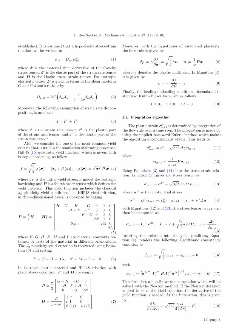
Table 1. Integration algorithm .
(I) Compute trial elastic stress
σtr = D. (εn+1εpn)
(II) Find Δγ by local iteration
(i) fk =√
32ϕk − σp,k, ϕk =
[σtr T . I−T
c .P .I−1c .σtr
]1/2
Ic = I + u√
32DP, u = Δγ
ϕk
(ii) f′k =
√3/2 dϕk
d(Δγ)− σ
′p,k
(iii) Δγk+1 = Δγk − fk
f′k
(iv) if |fk| > Tol then k = k + 1 go to (i)
(III) Update variables
σn+1 = I−1c .σtr
Remark : It is possible to incorporate the discussed modelinto an eight-node solid-shell finite element formulation by us-ing P Equation (5) [16] and can be successfully applied inmetal forming simulations. Furthermore, there exist also four-node shell element formulations which are applicable to thinshell structures by using P Equation (7) [17].
with, see Wali et al. [13],
dϕ
d (Δγ)= n.I−1
c
[−
√32ϕu
′Dn
](19)
u′ =√
3/2[σp − R′Δγ
σ2p
](20)
The solution of Equation (16) may then be effectivelyaccomplished by the simple local iteration procedure andthe whole integration algorithm is given in Table 1.
2.2 Extension to large deformation elastoplasticity
In the case of large deformation elastoplasticity, with ahypoelastic-based approach, Equation (1) will be replacedby a linear relationship of an arbitrary objective rate ofthe Kirchhoff stress τ and the elastic rate of deforma-tion tensor de. When considering the Green-Naghdi rateas in ABAQUS/Explicit, with no essential elastic volumechange (τ ≈ σ), this leads to
σo = σ − Ωσ + σΩ = D de (21)
where Ω is a skew-symmetric second-order Eulerian quan-tity given by
Ω = RRT (22)
and R is the rotation tensor of the polar decompositionof the deformation gradient F = vR = RU . The integra-tion algorithm defines the integration of the stress tensorassociated with the material behavior as
σn+1 = σtr√
3/2ΔγDnn+1 (23)
withσtr = ΔR σn ΔRT + D Δd (24)
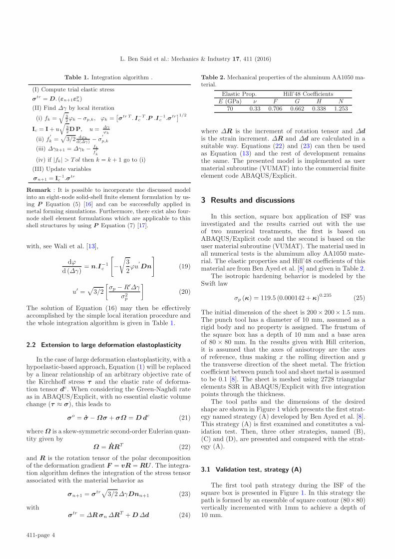
Table 2. Mechanical properties of the aluminum AA1050 ma-terial.
Elastic Prop. Hill’48 CoefficientsE (GPa) ν F G H N
70 0.33 0.706 0.662 0.338 1.253
where ΔR is the increment of rotation tensor and Δdis the strain increment. ΔR and Δd are calculated in asuitable way. Equations (22) and (23) can then be usedas Equation (13) and the rest of development remainsthe same. The presented model is implemented as usermaterial subroutine (VUMAT) into the commercial finiteelement code ABAQUS/Explicit.
3 Results and discussions
In this section, square box application of ISF wasinvestigated and the results carried out with the useof two numerical treatments, the first is based onABAQUS/Explicit code and the second is based on theuser material subroutine (VUMAT). The material used inall numerical tests is the aluminum alloy AA1050 mate-rial. The elastic properties and Hill’48 coefficients of thismaterial are from Ben Ayed et al. [8] and given in Table 2.
The isotropic hardening behavior is modeled by theSwift law
σp (κ) = 119.5 (0.000142 + κ)0.235 (25)
The initial dimension of the sheet is 200× 200× 1.5 mm.The punch tool has a diameter of 10 mm, assumed as arigid body and no property is assigned. The frustum ofthe square box has a depth of 10 mm and a base areaof 80 × 80 mm. In the results given with Hill criterion,it is assumed that the axes of anisotropy are the axesof reference, thus making x the rolling direction and ythe transverse direction of the sheet metal. The frictioncoefficient between punch tool and sheet metal is assumedto be 0.1 [8]. The sheet is meshed using 2728 triangularelements S3R in ABAQUS/Explicit with five integrationpoints through the thickness.
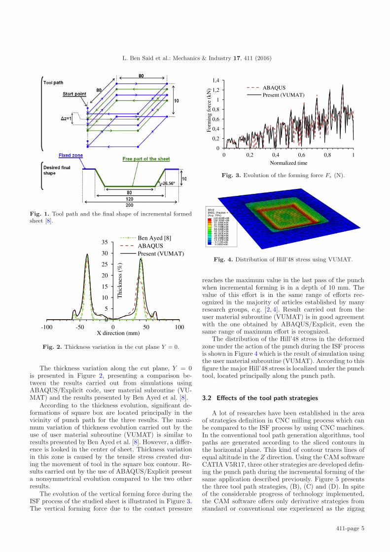
The tool paths and the dimensions of the desiredshape are shown in Figure 1 which presents the first strat-egy named strategy (A) developed by Ben Ayed et al. [8].This strategy (A) is first examined and constitutes a val-idation test. Then, three other strategies, named (B),(C) and (D), are presented and compared with the strat-egy (A).
3.1 Validation test, strategy (A)
The first tool path strategy during the ISF of thesquare box is presented in Figure 1. In this strategy thepath is formed by an ensemble of square contour (80×80)vertically incremented with 1mm to achieve a depth of10 mm.
411-page 4
L. Ben Said et al.: Mechanics & Industry 17, 411 (2016)
Fig. 1. Tool path and the final shape of incremental formedsheet [8].
-100 -500
5
10
15
20
25
30
35
0
Thi
ckne
ss(%
)
X directio50
Thi
ckne
ss (
%)
on (mm)
Ben AABAQPresen
100
yed [8]QUSnt (VUMAT)
Fig. 2. Thickness variation in the cut plane Y = 0.
The thickness variation along the cut plane, Y = 0is presented in Figure 2, presenting a comparison be-tween the results carried out from simulations usingABAQUS/Explicit code, user material subroutine (VU-MAT) and the results presented by Ben Ayed et al. [8].
According to the thickness evolution, significant de-formations of square box are located principally in thevicinity of punch path for the three results. The maxi-mum variation of thickness evolution carried out by theuse of user material subroutine (VUMAT) is similar toresults presented by Ben Ayed et al. [8]. However, a differ-ence is looked in the center of sheet. Thickness variationin this zone is caused by the tensile stress created dur-ing the movement of tool in the square box contour. Re-sults carried out by the use of ABAQUS/Explicit presenta nonsymmetrical evolution compared to the two otherresults.
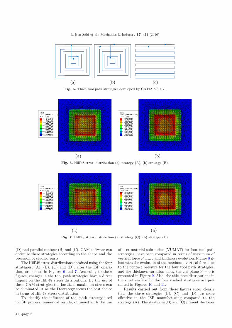
The evolution of the vertical forming force during theISF process of the studied sheet is illustrated in Figure 3.The vertical forming force due to the contact pressure
0
0,2
0,4
0,6
0,8
1
1,2
1,4
0
Form
ing
forc
e (k
N)
0 0,2 0,4
Norma
ABAQUSPresent (V
0,6
alized time
SVUMAT)
0,8
1
Fig. 3. Evolution of the forming force Fz (N).
Fig. 4. Distribution of Hill’48 stress using VUMAT.
reaches the maximum value in the last pass of the punchwhen incremental forming is in a depth of 10 mm. Thevalue of this effort is in the same range of efforts rec-ognized in the majority of articles established by manyresearch groups, e.g. [2, 4]. Result carried out from theuser material subroutine (VUMAT) is in good agreementwith the one obtained by ABAQUS/Explicit, even thesame range of maximum effort is recognized.
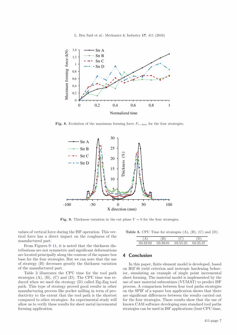
The distribution of the Hill’48 stress in the deformedzone under the action of the punch during the ISF processis shown in Figure 4 which is the result of simulation usingthe user material subroutine (VUMAT). According to thisfigure the major Hill’48 stress is localized under the punchtool, located principally along the punch path.
3.2 Effects of the tool path strategies
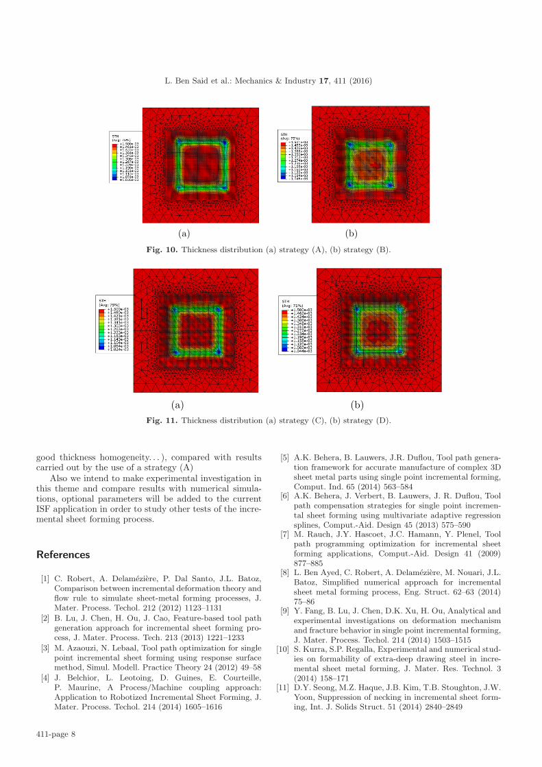
A lot of researches have been established in the areaof strategies definition in CNC milling process which canbe compared to the ISF process by using CNC machines.In the conventional tool path generation algorithms, toolpaths are generated according to the sliced contours inthe horizontal plane. This kind of contour traces lines ofequal altitude in the Z direction. Using the CAM softwareCATIA V5R17, three other strategies are developed defin-ing the punch path during the incremental forming of thesame application described previously. Figure 5 presentsthe three tool path strategies, (B), (C) and (D). In spiteof the considerable progress of technology implemented,the CAM software offers only derivative strategies fromstandard or conventional one experienced as the zigzag
411-page 5
L. Ben Said et al.: Mechanics & Industry 17, 411 (2016)
(a) (b) (c) Fig. 5. Three tool path strategies developed by CATIA V5R17.
(a) (b) Fig. 6. Hill’48 stress distribution (a) strategy (A), (b) strategy (B).
(a) (b) Fig. 7. Hill’48 stress distribution (a) strategy (C), (b) strategy (D).
(D) and parallel contour (B) and (C). CAM software canoptimize these strategies according to the shape and theprecision of studied parts.
The Hill’48 stress distributions obtained using the fourstrategies, (A), (B), (C) and (D), after the ISF opera-tion, are shown in Figures 6 and 7. According to thesefigures, changes in the tool path strategies have a directimpact on the Hill’48 stress distributions. By the use ofthese CAM strategies the localized maximum stress canbe eliminated. Also, the D-strategy seems the best choicein terms of Hill’48 stress distribution.
To identify the influence of tool path strategy usedin ISF process, numerical results, obtained with the use
of user material subroutine (VUMAT) for four tool pathstrategies, have been compared in terms of maximum ofvertical force Fz−max and thickness evolution. Figure 8 il-lustrates the evolution of the maximum vertical force dueto the contact pressure for the four tool path strategies,and the thickness variation along the cut plane Y = 0 ispresented in Figure 9. Also, the thickness distributions inthe sheet surface for the four studied strategies are pre-sented in Figures 10 and 11.
Results carried out from these figures show clearlythat the three strategies (B), (C) and (D) are moreeffective in the ISF manufacturing compared to thestrategy (A). The strategies (B) and (C) present the lower
411-page 6
L. Ben Said et al.: Mechanics & Industry 17, 411 (2016)
0
0,2
0,4
0,6
0,8
1
1,2
1,4
0
Max
imum
for
min
g f
orce
(kN
)
0,2
Str AStr BStr CStr D
0,4
Normalized
0,6 0
d time
,8 1
Fig. 8. Evolution of the maximum forming force Fz−max for the four strategies.
-100
S
S
S
S
-50
tr A
tr B
tr C
tr D
0
5
10
15
20
25
30
0
Thi
ckne
ss (
%)
X direction 50
(mm)100
Fig. 9. Thickness variation in the cut plane Y = 0 for the four strategies.
values of vertical force during the ISF operation. This ver-tical force has a direct impact on the roughness of themanufactured part.
From Figures 9–11, it is noted that the thickness dis-tributions are not symmetric and significant deformationsare located principally along the contour of the square boxbase for the four strategies. But we can note that the useof strategy (B) decreases greatly the thickness variationof the manufactured part.
Table 3 illustrates the CPU time for the tool pathstrategies (A), (B), (C) and (D). The CPU time was re-duced when we used the strategy (D) called Zig-Zag toolpath. This type of strategy proved good results in othermanufacturing process like pocket milling in term of pro-ductivity to the extent that the tool path is the shortestcompared to other strategies. An experimental study willallow us to verify these results for sheet metal incrementalforming application.
Table 3. CPU Time for strategies (A), (B), (C) and (D).
(A) (B) (C) (D)03:32:02 03:39:01 03:55:25 02:35:37
4 Conclusion
In this paper, finite element model is developed, basedon Hill’48 yield criterion and isotropic hardening behav-ior, simulating an example of single point incrementalsheet forming. The material model is implemented by theuse of user material subroutines (VUMAT) to predict ISFprocess. A comparison between four tool paths strategieson the SPIF of a square box application shows that thereare significant differences between the results carried outfor the four strategies. These results show that the use ofknown CAM software developing sum standard tool pathsstrategies can be used in ISF applications (best CPU time,
411-page 7
L. Ben Said et al.: Mechanics & Industry 17, 411 (2016)
(a) (b)
Fig. 10. Thickness distribution (a) strategy (A), (b) strategy (B).
(a) (b) Fig. 11. Thickness distribution (a) strategy (C), (b) strategy (D).
good thickness homogeneity. . . ), compared with resultscarried out by the use of a strategy (A)
Also we intend to make experimental investigation inthis theme and compare results with numerical simula-tions, optional parameters will be added to the currentISF application in order to study other tests of the incre-mental sheet forming process.
References
[1] C. Robert, A. Delameziere, P. Dal Santo, J.L. Batoz,Comparison between incremental deformation theory andflow rule to simulate sheet-metal forming processes, J.Mater. Process. Techol. 212 (2012) 1123–1131
[2] B. Lu, J. Chen, H. Ou, J. Cao, Feature-based tool pathgeneration approach for incremental sheet forming pro-cess, J. Mater. Process. Tech. 213 (2013) 1221–1233
[3] M. Azaouzi, N. Lebaal, Tool path optimization for singlepoint incremental sheet forming using response surfacemethod, Simul. Modell. Practice Theory 24 (2012) 49–58
[4] J. Belchior, L. Leotoing, D. Guines, E. Courteille,P. Maurine, A Process/Machine coupling approach:Application to Robotized Incremental Sheet Forming, J.Mater. Process. Techol. 214 (2014) 1605–1616
[5] A.K. Behera, B. Lauwers, J.R. Duflou, Tool path genera-tion framework for accurate manufacture of complex 3Dsheet metal parts using single point incremental forming,Comput. Ind. 65 (2014) 563–584
[6] A.K. Behera, J. Verbert, B. Lauwers, J. R. Duflou, Toolpath compensation strategies for single point incremen-tal sheet forming using multivariate adaptive regressionsplines, Comput.-Aid. Design 45 (2013) 575–590
[7] M. Rauch, J.Y. Hascoet, J.C. Hamann, Y. Plenel, Toolpath programming optimization for incremental sheetforming applications, Comput.-Aid. Design 41 (2009)877–885
[8] L. Ben Ayed, C. Robert, A. Delameziere, M. Nouari, J.L.Batoz, Simplified numerical approach for incrementalsheet metal forming process, Eng. Struct. 62–63 (2014)75–86
[9] Y. Fang, B. Lu, J. Chen, D.K. Xu, H. Ou, Analytical andexperimental investigations on deformation mechanismand fracture behavior in single point incremental forming,J. Mater. Process. Techol. 214 (2014) 1503–1515
[10] S. Kurra, S.P. Regalla, Experimental and numerical stud-ies on formability of extra-deep drawing steel in incre-mental sheet metal forming, J. Mater. Res. Technol. 3(2014) 158–171
[11] D.Y. Seong, M.Z. Haque, J.B. Kim, T.B. Stoughton, J.W.Yoon, Suppression of necking in incremental sheet form-ing, Int. J. Solids Struct. 51 (2014) 2840–2849
411-page 8

L. Ben Said et al.: Mechanics & Industry 17, 411 (2016)
[12] F. Han, J. MO, H. Qi et al., Springback prediction for in-cremental sheet forming based on FEM-PSONN technol-ogy, Trans. Nonferrous Met. Soc. China 23 (2013) 1061–1071
[13] M. Wali, H. Chouchene, L. Ben Said, F. Dammak,One-equation integration algorithm of a generalizedquadratic yield function with Chaboche non-linearisotropic/kinematic hardening, Int. J. Mech. Sci. 92(2015) 223–232
[14] J. Mars, M. Wali, A. Jarraya, F. Dammak, A. Dhiab,Finite element implementation of an orthotropic plastic-ity model for sheet metal in low velocity impact simula-tions, Thin Wall. Struct. 89 (2015) 93–100
[15] R. Hill, A theory of the yielding and plastic flow ofanisotropic metals, Proc. Roy. Soc. London A 193 (1948)281–297
[16] A. Hajlaoui, A. Jarraya, I. Kallel-Kamoun, F. Dammak,Buckling analysis of a laminated composite plate withdelaminations using the enhanced assumed strain solidshell element, J. Mech. Sci. Technol. 26 (2012) 3213–3221
[17] F. Dammak, S. Abid, A. Gakwaya, G. Dhatt, A formula-tion of the nonlinear discrete Kirchhoff quadrilateral shellelement with finite rotations and enhanced strains, RevueEuropeenne des Elements Finis 14 (2005) 7–31
411-page 9