effi+ r - ett - energie transfert thermique · • en 1886 - ventilation for buildings – air...
TRANSCRIPT

Single fl ow heat pumpDESHU option available
ENVIRONMENTALCLIMATE CONTROLEQUIPMENT & SOLUTIONS
SPECIALRENOV
EFFI+ R
www.ett.fr

ETT may change equipment technical data without prior notice.Specifi cations given in this document are for information only and are not contractual.
2
2016 - 02 / EFFI+RMARK-BRO_10.00-EN
C O N T E N T S■ General description ....................................................................................................................................... 03■ Operating principles ...................................................................................................................................... 04■ Description ........................................................................................................................................................... 05■ Control description ......................................................................................................................................... 07■ Main options ....................................................................................................................................................... 08
Technical features■ Type R106 – R107 – R108 – R110 .............................................................................................................. 09■ Type R212 – R214 – R216 .............................................................................................................................. 13■ Type R218 – R221 .............................................................................................................................................. 17■ Type R322 – R325 – R328 – R333 .............................................................................................................. 21
Dimensions and connections■ Type R106 – R107 – R108 – R110 .............................................................................................................. 10■ Type R212 – R214 – R216 .............................................................................................................................. 14■ Type R218 – R221 .............................................................................................................................................. 18■ Type R322 – R325 – R328 – R333 .............................................................................................................. 22
Arrangements■ Arrangements .................................................................................................................................................... 25
Auxiliaries■ Hot water coils ................................................................................................................................................... 26■ Electric heaters .................................................................................................................................................. 28
Preheating■ Water recovery coils ...................................................................................................................................... 29
Options weight■ Options weight .................................................................................................................................................. 31
DESHU Option■ Dehumidifi cation option with heat recovery through in-line condenser ................... 32
Sound level■ Sound level........................................................................................................................................................... 35
Compatibility with previous range■ Series 1 (R106 - R107 - R108 - R110) ....................................................................................................... 36■ Series 2 (R212 - R214 - R216 - R218 - R221) ........................................................................................ 37■ Series 3 (R322 - R325 - R328 - R333) ....................................................................................................... 38
Installation accessories■ Roof curbs ............................................................................................................................................................. 39■ Feet ........................................................................................................................................................................... 41
Probes connection scheme■ Probes connection scheme ..................................................................................................................... 42
E N E R G I ET R A N S F E R TT H E R M I Q U E

ETT may change equipment technical data without prior notice.Specifi cations given in this document are for information only and are not contractual.
3
2016 - 02 / EFFI+RMARK-BRO_10.00-EN
General description
• Machinery Directive 2006/42/EC - Operator's safety• Low Voltage Directive 2006/95/EC - Electricity• EMC Directive 2004/108/EC - Electromagnetic
Compatibility• 2009/142/EC Directive - Gas Appliances
• EN 1886 - Ventilation for buildings – Air Handling Units – Mechanical performance
• EN 60204-1 - Safety of machinery – Electrical equipment of machines
Moreover, each unit is delivered with an EC certifi cate of conformity and complies with the standards listed below:
All units are checked and tested at the factory prior to shipment. A control certifi cate is issued for each unit.ETT Quality organisation is certifi ed ISO 9001:2008 (AFNOR Certifi cate 1994/2016f).
We placed ease of operation at the heart of our units design:
• The separate technical section facilitates service and control of the unit and allows measurement and adjustment during operation.
• The BEST controller is specifi cally designed for this application. It allows great fl exibility, thus optimum performance of the ETT unit through a user-friendly interface, be it local or remote (with remote display, PC or BMS).
The ETT packaged unit is delivered ready to operate. Its full aluminium structure (frame & casing) ensures an excellent corrosion protection (20-year anti-corrosion guarantee).The ETT unit can be installed either at ground level or on a roof.ECODESIGN involves DECONSTRUCTION: ETT units are 98% recyclable (re-use and recycling rates based on EFFI+ 220).
20-year guarantee against corrosion
2222222222222222222222222222222222220000000000000000000000000000000000000000000--------------------yyyyyyyyyyyyyyyyyyyyyyyyyyyyyyyyyyyyyyyyyyyyyyyeeeeeeeeeeeeeeeeeeeeeeeeeeeeeeeeeeeeeeeeeeeeeaaaaaaaaaaaaaaaaaaaaaaaaaaaaaaaaaaaaaaarrrrrrrrrrrrrrrrrrrrrrrrrrrrrrrrrrr gggggggggggggggggggggggggggggggggggggggggggggguuuuuuuuuuuuuuuuuuuuuuuuuuuuuuuuuuuuuuuuuuaaaaaaaaaaaaaaaaaaaaaaaaaaaaaaaaaaaaaaaaaaaaaaarrrrrrrrrrrrrrrrrrrrrrrrrrrrrrrrrrrraaaaaaaaaaaaaaaaaaaaaaaaaaaaaaaaaaaaaaaaaaaaannnnnnnnnnnnnnnnnnnnnnnnnnnnnnnnnnnnnttttttttttttttttttttttttttttttttttttteeeeeeeeeeeeeeeeeeeeeeeeeeeeeeeeeeeeeeeeeeeeeeeeeeeeeeeeeeeeeeeeeeeeeeeeeeeee aaaaaaaaaaaaaaaaaaaaaaaaaaaaaaaaaaaaaaaaaaaaaggggggggggggggggggggggggggggggggggggggggggggggggaaaaaaaaaaaaaaaaaaaaaaaaaaaaaaaaaaaaaaaaaaaaaaaaaiiiiiiiiiiiiiiiiiiiiiiiiiiiiiiiinnnnnnnnnnnnnnnnnnnnnnnnnnnnnnnnnnnnnnnnnnnsssssssssssssssssssssssssssssssssssssssttttttttttttttttttttttttttttttttttttt cccccccccccccccccccccccccccccccccccccccccccoooooooooooooooooooooooooooooooooooooooooooooorrrrrrrrrrrrrrrrrrrrrrrrrrrrrrrrrrrrrrrrrrrrrrrrrrrrrrrrrrrrrrrrrrrrooooooooooooooooooooooooooooooooooooooooooooosssssssssssssssssssssssssssssssssssssssiiiiiiiiiiiiiiiiiiiiiiiiiiiiiiiiiooooooooooooooooooooooooooooooooooooooooooooooooonnnnnnnnnnnnnnnnnnnnnnnnnnnnnnnnnnnnnnnnnn
Our technical choices have several impacts on the environment
• Legal and regulatory framework:- In accordance with Directive 2008/98/EC on waste, clause 26: "The polluter-pays principle is a
guiding principle at European and international levels. The waste producer and the waste holder should manage the waste in a way that guarantees a high level of protection of the environment and human health.", ETT is a member of "Eco-systèmes Pro".
- In accordance with articles 5.3, 5.4 and 11 of Regulation (EC) No. 303/2008, ETT holds a certifi cate of capability to handle refrigerants (no. 637).
• Aluminium: a good choice for the planet!- Aluminium is endlessly 100% recyclable.- Recycling covers over 30% of aluminium needs.
• Low polluting ETT manufacturing process:- Selective sorting, waste recovery, 60% of waste is recycled.- No paint on casings, no use of solvent.- ISO 14001 Certifi cation (Environmental Management System).
• Consumables: effi cient waste management:- Filtration: ETT units include "ecodesigned" air fi lters (selective sorting: frame - grille - media)
ETT may change equipment technical data without prior notice.Specifi cations given in this document are for information only and are not contractual.
4
2016 - 02 / EFFI+RMARK-BRO_10.00-EN
Operating principles
1
2 3
+ + _
1
2 3
+_
1
3
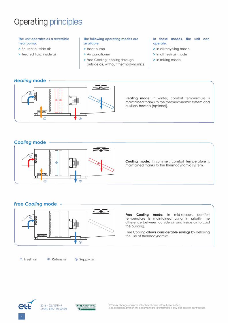
The following operating modes are available:> Heat pump> Air conditioner> Free Cooling: cooling through
outside air, without thermodynamics
In these modes, the unit can operate:> In all recycling mode> In all fresh air mode> In mixing mode
The unit operates as a reversible heat pump:> Source: outside air> Treated fl uid: inside air
1 Fresh air 2 Return air 3 Supply air
Heating mode
Cooling mode
Free Cooling mode
Heating mode: In winter, comfort temperature is maintained thanks to the thermodynamic system and auxiliary heaters (optional).
Cooling mode: In summer, comfort temperature is maintained thanks to the thermodynamic system.
Free Cooling mode: In mid-season, comfort temperature is maintained using in priority the difference between outside air and inside air to cool the building.
Free Cooling allows considerable savings by delaying the use of thermodynamics.

ETT may change equipment technical data without prior notice.Specifi cations given in this document are for information only and are not contractual.
5
2016 - 02 / EFFI+RMARK-BRO_10.00-EN
Description
The ETT packaged unit comprises 3 different sections:
1 The external section allows thermal exchanges with the environment.
2 The separate technical section houses the refrigeration components, the electrical board and the control components.
3 The internal section ensures air change and air treatment.
■ Rigid, compact and lightweight packaged unit, perfectly weather-resistant, with a 20-year anti corrosion guarantee on casing.
■ Watertight floor with drainage outlets around the unit, connected to rubber siphons.
■ Aluminium vertical panels and roof, mounted on aluminium frame.
■ Access through large “easy to remove” panels. Panels are closed with square locks. Doors tightness is ensured by a flexible gasket under compression, providing an ideal elasticity day after day (French standard NF EN 1886).
■ High performance supply air plug fan to avoid losses due to pulley-belt transmissions, thus improving unit energy efficiency.
■ Inner acoustic and thermal insulation on panels using 25 mm M0 glass wool, in accordance with French Public Access Buildings regulations (Article CH36).
■ Floor sound and thermal insulation using 20 mm acoustic foam.
■ 2-damper mixing box including a motorised fresh air damper with bird proof grid and a return air damper to ensure the desired proportions and optimise Free Cooling phases. Dampers have extruded aluminium blades with low pressure drop thanks to their plane wing profile and flexible gasket which ensures excellent air tightness. The damper frame is made of tightness class 3 aluminium.
Optimised defrosting:
Defrosting principle:� The condensation of humidity produces frost on the coil.� The concerned refrigeration system and propeller fan stop operating
(simultaneous defrosting cycles are banned).� The refrigeration system 4-way valve reverses: during defrosting, the
coil operates as a condenser.� Supply air flows downwards.� The coil is dried.� The other refrigeration circuit continues to operate normally.
Aluminium frame and casing:
ETT may change equipment technical data without prior notice.Specifi cations given in this document are for information only and are not contractual.
6
2016 - 02 / EFFI+RMARK-BRO_10.00-EN
Description
■ Filter assembly with easy-to-remove ecodesign filters - 98 mm pleated media, efficiency 95% ASHRAE gravimetric (G4) for longer lifetime and lower pressure drops, pressure switch for fouling control.
■ Supply air plug fan. This technology avoids losses due to pulley-belt transmissions.
■ Electronically commutated motors allow: � reduced kickback during start-up when textile ducts are used (soft start mode); � maximum rotation speed regulation according to pressure drops on site; � reduced speed operation in Free Cooling mode to save energy (VDP operation).
■ Refrigeration circuits compliant with European directive on pressure equipment (PED 97/23/EC).
■ R410A refrigerant. ■ Direct expansion internal exchanger,
made with copper pipes and aluminium fins and frame, coupled with a thermostatic expansion valve in heat pump mode.
■ Direct expansion external exchanger, made with copper pipes and aluminium fins and frame, coupled with a thermostatic expansion valve in heat pump mode.
■ Optimised defrosting thanks to the new design of the external section and the integration of a Ø 800 propeller fan with supply air downwards (optimised for ecodesign).
■ 2 expansion valves per circuit and per refrigeration cycle to optimise the efficiency of each evaporator cycle and reduce energy consumption.
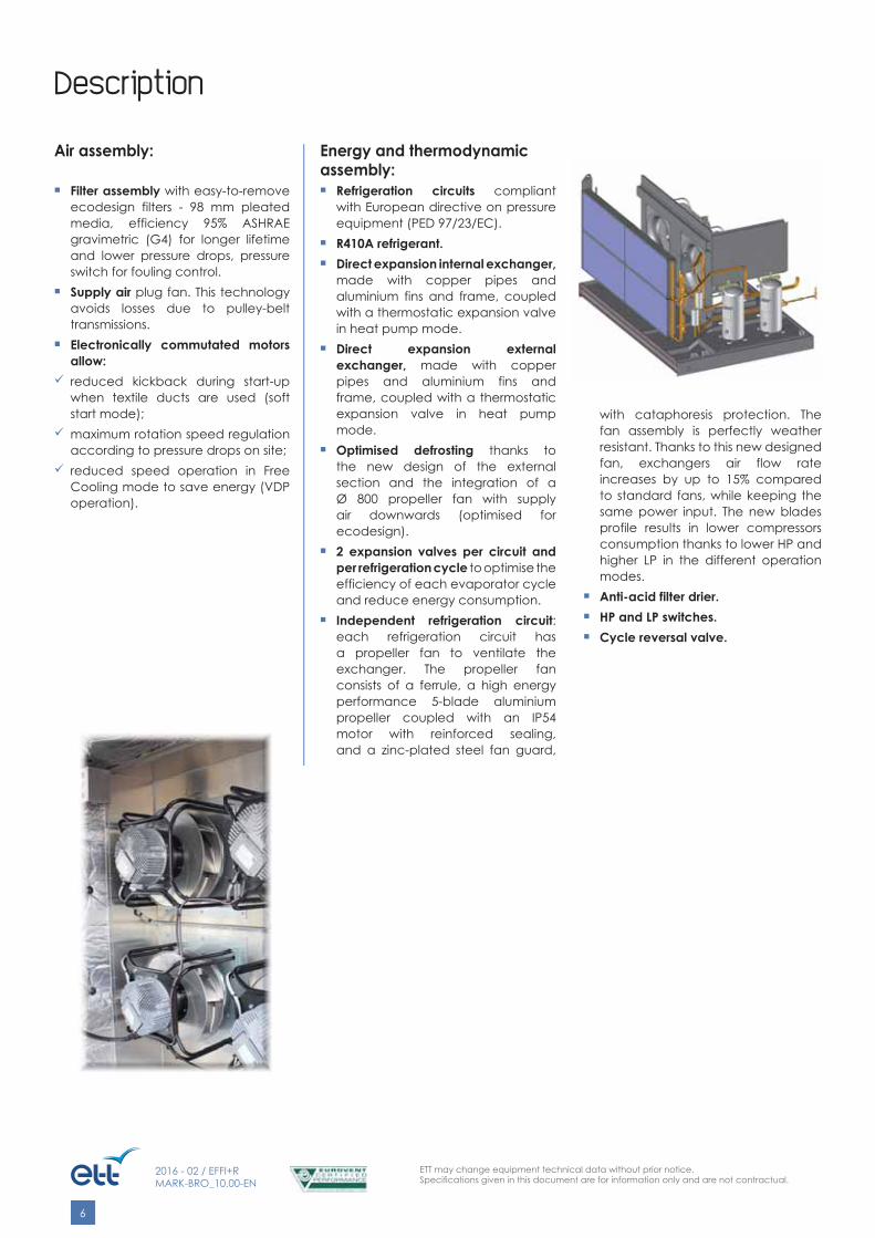
■ Independent refrigeration circuit: each refrigeration circuit has a propeller fan to ventilate the exchanger. The propeller fan consists of a ferrule, a high energy performance 5-blade aluminium propeller coupled with an IP54 motor with reinforced sealing, and a zinc-plated steel fan guard,
with cataphoresis protection. The fan assembly is perfectly weather resistant. Thanks to this new designed fan, exchangers air flow rate increases by up to 15% compared to standard fans, while keeping the same power input. The new blades profile results in lower compressors consumption thanks to lower HP and higher LP in the different operation modes.
■ Anti-acid filter drier. ■ HP and LP switches. ■ Cycle reversal valve.
Energy and thermodynamic assembly:
Air assembly:

ETT may change equipment technical data without prior notice.Specifi cations given in this document are for information only and are not contractual.
7
2016 - 02 / EFFI+RMARK-BRO_10.00-EN
■ Electrical board compliant with European standards EN 15-100 and EN 60204-01, including: � ETT controller with display. � Power switch with lockable external handle for full load cut-off. Connection using standard universal cable. Optional copper/aluminium connection boxes. � 400-230-24 volts transformer for regulation and control circuits. � Faults synthesis with pending dry contact on terminal. � Numbered terminal blocks with disconnecting terminals for remote controls and transfers. � Terminal block for compressors load shedding. � Internal wiring with numbered ferrules at both extremities. � Ik3 breaking capacity of basis 10 kA. � All components protected by circuit breakers. � LV distribution rated voltage compliant with French standards, i.e. rated voltage of 230/400V. French standards also set minimum and maximum acceptable values at the user supply point (average value for 10lm) within a -10%/+10% range from rated values and maximum acceptable value of the voltage drop gradient to 2%. The voltage drop gradient represents the additional voltage drop created on a network point if 1 KW single-phase is added on this point.
■ CTN type temperature probes. Their accuracy and liability have been tested and validated both at the factory and on site.
■ One or more BEST type controllers (Building Energy Saving Technology) especially developed by ETT for this range of units. Programs are updated annually in order to add functions requested for some applications and to optimise units electricity consumption.
The microprocessor, memory and controllers size are adapted to the chosen applications and options by integrating a program set-up in the factory out of 160 possible confi gurations. The controller is in a plastic box which guarantees a high mechanical protection and reduces electrostatic shock threats.
Among other functions, the controller includes: � On/Off with remote contact or vacancy contact. � On/Off according to programmed schedule (2 time slots per day). � Fault synthesis via dry contact for transfer on customer system. � 2 setpoints (cooling and heating) according to the European directive 2002/91/EC. � Security management (freezestat, smoke detector, HP switch, etc.) and faults management. � Optimisation and equalisation of compressors operating time.
� Flash-type analogue and economical management of alternate defrostings for each refrigeration circuit using frost detection and end of defrosting through analogue probes, stop of the concerned exchanger’s ventilation, coil drying and starting of a new heating cycle in heat pump mode. External coils angled position and downward supply air flow help blowing water away from the coil, ensuring efficient defrosting. Concerning multi-circuits units, comfort and energy savings are ensured by banning simultaneous defrostings. � Economiser management (Free Cooling) through inside temperature analysis and comparison between return air and outside air temperatures. � Compressors stages management giving priority to the highest COP and EER in part load. � Frost protection. � Auxiliaries management (possibility of banning according to outside temperature). � Night energy consumption management with compressors' use limitation (Night Cooling). � Written faults history (no code needed) with time and outside temperature display. � Operating hours counting (unit, compressors and auxiliaries). � Air quality control with CO2 probe to optimise fresh air quantities to introduce, therefore limiting energy consumption.
Control description
Electrical assembly: Control assembly:

ETT may change equipment technical data without prior notice.Specifi cations given in this document are for information only and are not contractual.
8
2016 - 02 / EFFI+RMARK-BRO_10.00-EN
Main options
Frame - Casing ■ Motorised external damper for supply air (2006/42/EC Directive) ■ Supply air on side, supply air on top ■ Double skin in internal section, 13/10 AG, 25 mm
Acoustics ■ Technical section acoustic insulation using STOPFLAM fl exible fi re-proof polyurethane foam ■ Fresh air cowl sound insulation ■ Compressors acoustic jackets
Air handling ■ Dial pressure gauges ■ Filters fouling analogue control (FFAC) ■ Backed-up self-contained smoke detector ■ Epoxy coating on fan & vinyl coating on exchangers ■ Supply air fan available pressure 400 Pa max. ■ Operation in all recycling or all fresh air mode (not available for public access buildings) ■ G4 refi llable fi lters, 98 mm thick ■ 1 set of spare G4 fi lters, 98 mm thick ■ G1 metal fi lters on fresh air, 23 mm thick ■ F7 or F9 opacimetric fi lters, 98 mm thick
Thermodynamics ■ HP and LP pressure gauges ■ Electronic expansion valves
Thermal exchangers ■ 2-stage electric heater ■ Triac ■ 2-row hot water coil with analogue freezestat ■ Mounted progressive 3-way valve on hot water ■ Mounted stop valve + TA regulating valve on outlet ■ Water recovery coil on food refrigeration ■ In-line condenser
Electricity ■ Unit global energy metering
Laying ■ Adapter interface on existing roof curb ■ Aluminium connection roof curb
Control ■ Min. fresh air control using turret contacts (2 max.) ■ Year-round operation (compressor cooling mode authorisation with -5°C < outside temp. < +15°C) ■ Banning of Free Cooling using specifi c humidity comparison (with 2 hygro probes) ■ Hygrometry probe (for external humidifi er control)

ETT may change equipment technical data without prior notice.Specifi cations given in this document are for information only and are not contractual.
9
2016 - 02 / EFFI+RMARK-BRO_10.00-EN
Technical features
NAME Unit R106 R107 R108 R110
SPEC
IFIC
ATIO
NS
Rated air fl ow rate m3/h 6000 7500 8500 10500
Min. air fl ow rate m3/h 4500 6500 7500 10000
Max. air fl ow rate m3/h 11000 11000 11000 11000
COOLING MODE (1)
Net cooling capacity kW 30.5 36.8 41.4 49.9
Net absorbed electrical power kW 9.2 12.2 14.7 20.0
Net EER kW/kW 3.33 3.01 2.82 2.5
Sensible/Total capacity ratio 0.81 0.79 0.79 0.77
HEATING MODE (1)
Net heating capacity kW 31.9 39.1 44.8 55.1
Net absorbed electrical power kW 8.4 10.7 12.7 16.7
Net COP kW/kW 3.82 3.66 3.53 3.3
Power stages 1
ELEC
TRIC
AL
CONN
ECTIO
N Maximum absorbed electrical power (2) kW 13.5 16.8 19.3 27.3
Total installed electrical power (2) (4) kW 19.7 22.6 24.9 32.0
Rated current (2) A 34 39 44 54
Starting current (2) A 132 154 188 226
FAN
SUPPLY AIR
Absorbed electrical power (1) kW 0.9 1.2 1.4 1.9
SFPv (EN 13779) kW/(m3/s) 0.55 0.56 0.59 0.66
GEN
ERA
L
EUROVENT Energy Effi ciency class in Heating mode A A A B
Sound power level on supply air side (EUROVENT certifi ed) (1) dB(A) 74 77 79 84
Outside sound power level (EUROVENT certifi ed) (1) dB(A) 79 84 86 91
Resulting outside sound pressure at 10m,ref. 2x10⁻⁵ in free fi eld (1) dB(A) 51 56 58 63
Filters effi ciency G4
Filters dimensions & number mm (2x) 498*498*98(2x) 498*595*98
Max. outside operating temperature in Cooling mode °C 45
Min. outside operating temperature in Cooling mode °C 15
Min. outside operating temperature in Heating mode °C -15
Min. internal coil inlet temperature in Heating/Cooling mode °C 12/18
Unit weight without options (3) kg 570 570 570 610
Connection roof curb weight kg 80
(1) Cooling mode: 35°C DB - 27°C DB 47%/19°C WBHeating mode: 7°C DB - 20°C DB 60%/15°C WBExternal Static Pressure (ESP): 200 Pa(2) Out of electrical resistances
(3) Weight for 400 Pa available. For hot water coils and electric heaters weight, please consult "Auxiliaries". For installation accessories weight, please consult "Installation accessories".400 V - 50 Hz 3-phase power supply + earth without neutral(4) Power to be used for power cables selection
Type R106 - R107R108 - R110

ETT may change equipment technical data without prior notice.Specifi cations given in this document are for information only and are not contractual.
10
2016 - 02 / EFFI+RMARK-BRO_10.00-EN
Dimensions and connections
Length Width HeightCasing dimensions 2800 mm 1600 mm 1500 mm
Transport overall dimensions 2850 mm 1650 mm 1660 mm
Front view:
Top view:
Return air side view: Supply air side view:
SUPPLY AIR below
Nota:Nota: Fresh air cowls laying shall be made by the installer.
Type R106 - R107R108 - R110
1 Fresh air
2 Return air3 Supply airA Access
Power supply
C Technical sectionProvide 400 mm clearance (minimum) to allow air passage below the unit.
■ Provide a maintenance zone of 1600 mm on technical section side.
ETT may change equipment technical data without prior notice.Specifi cations given in this document are for information only and are not contractual.
11
2016 - 02 / EFFI+RMARK-BRO_10.00-EN
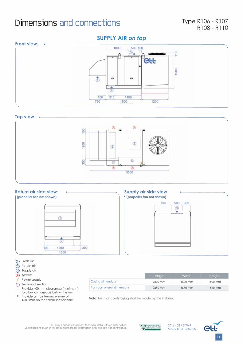
Length Width HeightCasing dimensions 2800 mm 1600 mm 1500 mm
Transport overall dimensions 2850 mm 1650 mm 1660 mm
Front view:
Top view:
Return air side view: Supply air side view:
SUPPLY AIR on top
(propeller fan not shown) (propeller fan not shown)
Nota:Nota: Fresh air cowls laying shall be made by the installer.
Dimensions and connections Type R106 - R107R108 - R110
1 Fresh air
2 Return air3 Supply airA Access
Power supply
C Technical sectionProvide 400 mm clearance (minimum) to allow air passage below the unit.
■ Provide a maintenance zone of 1600 mm on technical section side.
ETT may change equipment technical data without prior notice.Specifi cations given in this document are for information only and are not contractual.
12
2016 - 02 / EFFI+RMARK-BRO_10.00-EN
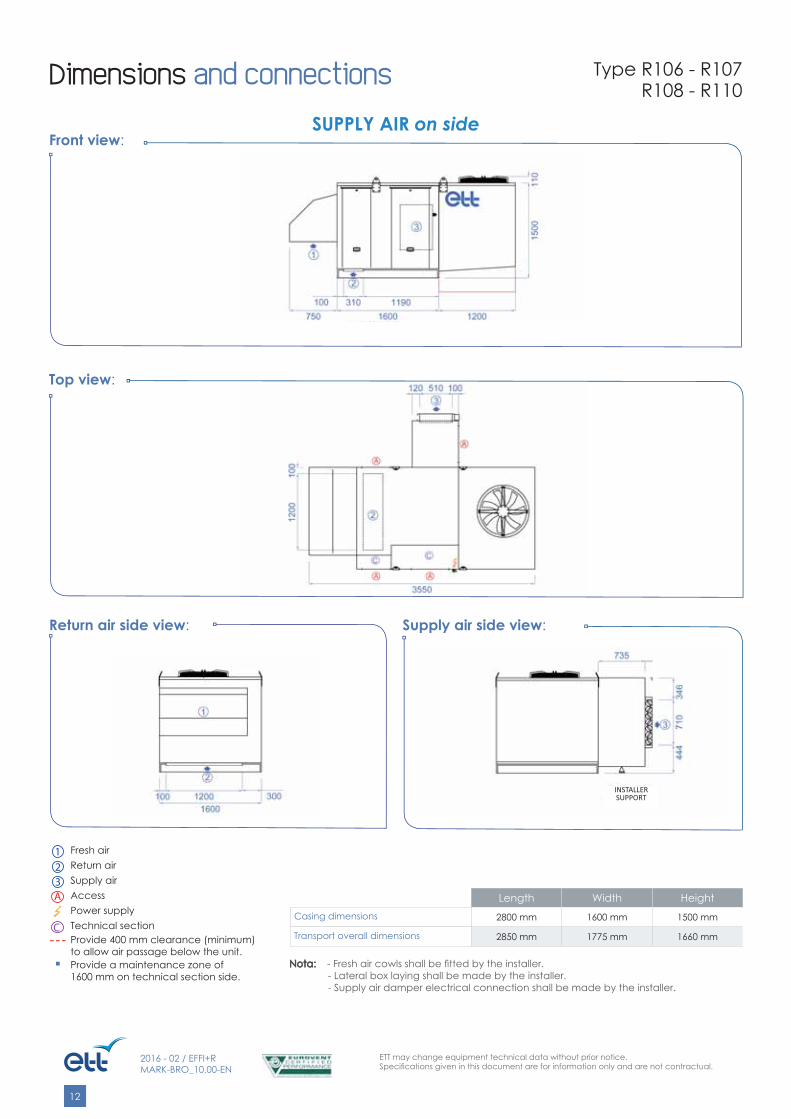
Length Width HeightCasing dimensions 2800 mm 1600 mm 1500 mm
Transport overall dimensions 2850 mm 1775 mm 1660 mm
Front view:
Top view:
Return air side view: Supply air side view:
SUPPLY AIR on side
INSTALLER SUPPORT
Nota: Nota: - Fresh air cowls shall be fi tted by the installer.- Lateral box laying shall be made by the installer.- Supply air damper electrical connection shall be made by the installer.
Dimensions and connections Type R106 - R107R108 - R110
1 Fresh air
2 Return air3 Supply airA Access
Power supply
C Technical sectionProvide 400 mm clearance (minimum) to allow air passage below the unit.
■ Provide a maintenance zone of 1600 mm on technical section side.
ETT may change equipment technical data without prior notice.Specifi cations given in this document are for information only and are not contractual.
13
2016 - 02 / EFFI+RMARK-BRO_10.00-EN
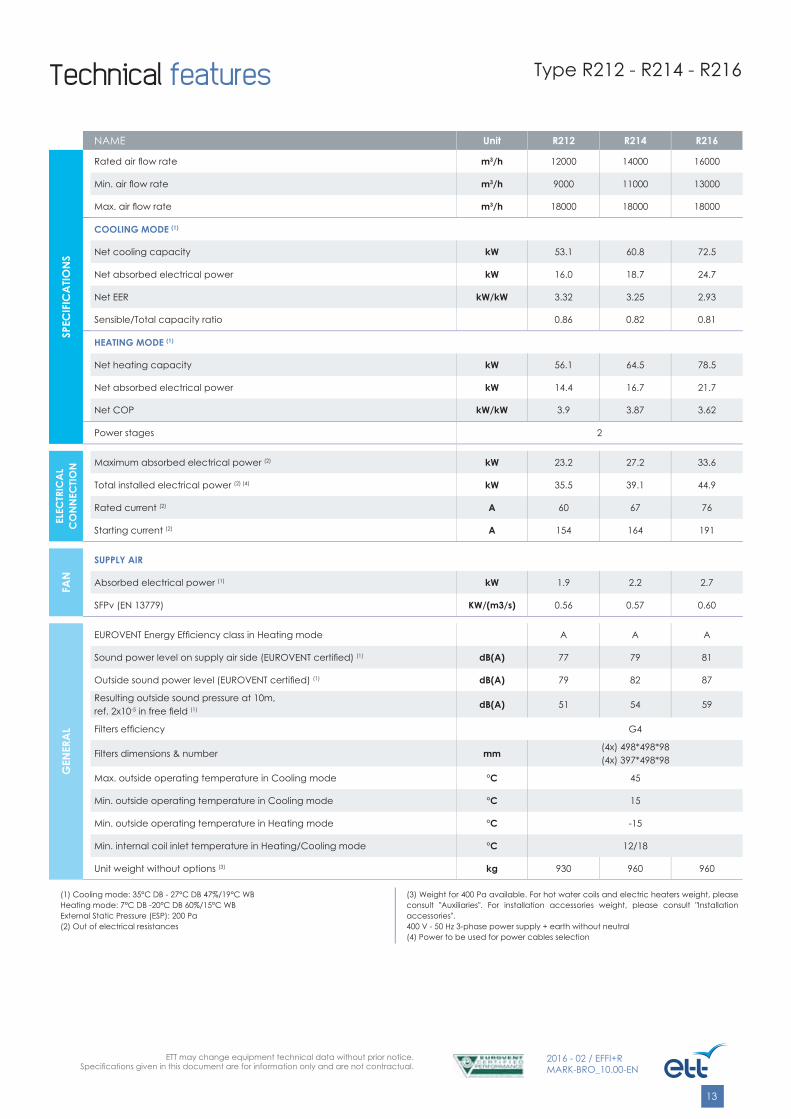
Technical features Type R212 - R214 - R216
NAME Unit R212 R214 R216
SPEC
IFIC
ATIO
NS
Rated air fl ow rate m3/h 12000 14000 16000
Min. air fl ow rate m3/h 9000 11000 13000
Max. air fl ow rate m3/h 18000 18000 18000
COOLING MODE (1)
Net cooling capacity kW 53.1 60.8 72.5
Net absorbed electrical power kW 16.0 18.7 24.7
Net EER kW/kW 3.32 3.25 2.93
Sensible/Total capacity ratio 0.86 0.82 0.81
HEATING MODE (1)
Net heating capacity kW 56.1 64.5 78.5
Net absorbed electrical power kW 14.4 16.7 21.7
Net COP kW/kW 3.9 3.87 3.62
Power stages 2
ELEC
TRIC
AL
CO
NN
ECTIO
N Maximum absorbed electrical power (2) kW 23.2 27.2 33.6
Total installed electrical power (2) (4) kW 35.5 39.1 44.9
Rated current (2) A 60 67 76
Starting current (2) A 154 164 191
FAN
SUPPLY AIR
Absorbed electrical power (1) kW 1.9 2.2 2.7
SFPv (EN 13779) KW/(m3/s) 0.56 0.57 0.60
GEN
ERA
L
EUROVENT Energy Effi ciency class in Heating mode A A A
Sound power level on supply air side (EUROVENT certifi ed) (1) dB(A) 77 79 81
Outside sound power level (EUROVENT certifi ed) (1) dB(A) 79 82 87
Resulting outside sound pressure at 10m,ref. 2x10⁻⁵ in free fi eld (1) dB(A) 51 54 59
Filters effi ciency G4
Filters dimensions & number mm (4x) 498*498*98(4x) 397*498*98
Max. outside operating temperature in Cooling mode °C 45
Min. outside operating temperature in Cooling mode °C 15
Min. outside operating temperature in Heating mode °C -15
Min. internal coil inlet temperature in Heating/Cooling mode °C 12/18
Unit weight without options (3) kg 930 960 960
(1) Cooling mode: 35°C DB - 27°C DB 47%/19°C WBHeating mode: 7°C DB -20°C DB 60%/15°C WBExternal Static Pressure (ESP): 200 Pa(2) Out of electrical resistances
(3) Weight for 400 Pa available. For hot water coils and electric heaters weight, please consult "Auxiliaries". For installation accessories weight, please consult "Installation accessories".400 V - 50 Hz 3-phase power supply + earth without neutral(4) Power to be used for power cables selection
ETT may change equipment technical data without prior notice.Specifi cations given in this document are for information only and are not contractual.
14
2016 - 02 / EFFI+RMARK-BRO_10.00-EN
EFFI
+ R
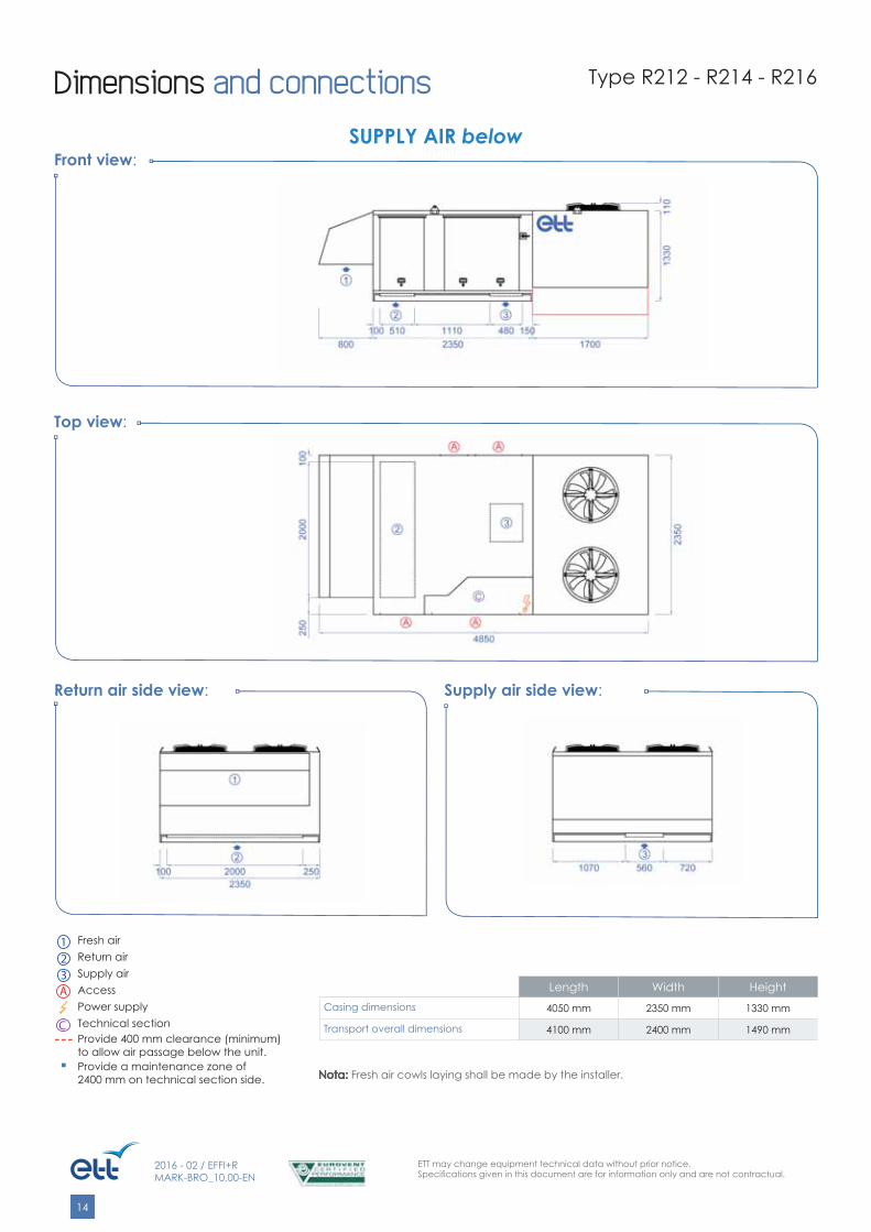
Dimensions and connections
Length Width HeightCasing dimensions 4050 mm 2350 mm 1330 mm
Transport overall dimensions 4100 mm 2400 mm 1490 mm
Type R212 - R214 - R216
Front view:
Top view:
Return air side view: Supply air side view:
SUPPLY AIR below
Nota:Nota: Fresh air cowls laying shall be made by the installer.
1 Fresh air
2 Return air3 Supply airA Access
Power supply
C Technical sectionProvide 400 mm clearance (minimum) to allow air passage below the unit.
■ Provide a maintenance zone of 2400 mm on technical section side.
ETT may change equipment technical data without prior notice.Specifi cations given in this document are for information only and are not contractual.
15
2016 - 02 / EFFI+RMARK-BRO_10.00-EN
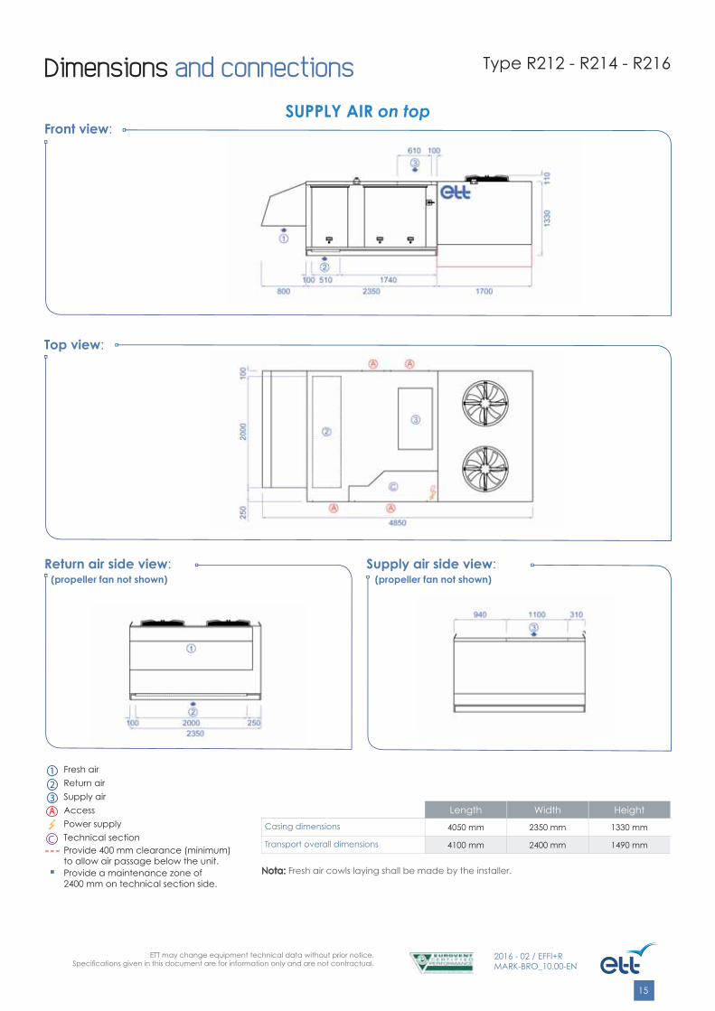
Length Width HeightCasing dimensions 4050 mm 2350 mm 1330 mm
Transport overall dimensions 4100 mm 2400 mm 1490 mm
Front view:
Top view:
Return air side view: Supply air side view:
SUPPLY AIR on top
(propeller fan not shown) (propeller fan not shown)
Nota:Nota: Fresh air cowls laying shall be made by the installer.
Dimensions and connections Type R212 - R214 - R216
1 Fresh air
2 Return air3 Supply airA Access
Power supply
C Technical sectionProvide 400 mm clearance (minimum) to allow air passage below the unit.
■ Provide a maintenance zone of 2400 mm on technical section side.

ETT may change equipment technical data without prior notice.Specifi cations given in this document are for information only and are not contractual.
16
2016 - 02 / EFFI+RMARK-BRO_10.00-EN
Length Width HeightCasing dimensions 4050 mm 2350 mm 1330 mm
Transport overall dimensions 4100 mm 2525 mm 1490 mm
Front view:
Top view:
Return air side view: Supply air side view:
SUPPLY AIR on side
INSTALLER SUPPORT
Nota: Nota: - Fresh air cowls shall be fi tted by the installer.- Lateral box laying shall be made by the installer.- Supply air damper electrical connection shall be made by the installer.
Dimensions and connections Type R212 - R214 - R216
1 Fresh air
2 Return air3 Supply airA Access
Power supply
C Technical sectionProvide 400 mm clearance (minimum) to allow air passage below the unit.
■ Provide a maintenance zone of 2400 mm on technical section side.

ETT may change equipment technical data without prior notice.Specifi cations given in this document are for information only and are not contractual.
17
2016 - 02 / EFFI+RMARK-BRO_10.00-EN
Technical features
NAME Unit R218 R221
SPEC
IFIC
ATIO
NS
Rated air fl ow rate m3/h 18000 21000
Min. air fl ow rate m3/h 15000 19000
Max. air fl ow rate m3/h 23000 23000
COOLING MODE (1)
Net cooling capacity kW 84.8 102.2
Net absorbed electrical power kW 29.8 39.2
Net EER kW/kW 2.85 2.61
Sensible/Total capacity ratio 0.82 0.77
HEATING MODE (1)
Net heating capacity kW 91 111.2
Net absorbed electrical power kW 25.1 33.2
Net COP kW/kW 3.62 3.35
Power stages 2
ELEC
TRIC
AL
CO
NN
ECTIO
N Maximum absorbed electrical power (2) kW 38.7 54.3
Total installed electrical power (2) (4) kW 49.5 63.7
Rated current (2) A 87 105
Starting current (2) A 230 278
FAN
SUPPLY AIR
Absorbed electrical power (1) kW 3.0 3.8
SFPv (EN 13779) KW/(m3/s) 0.60 0.65
GEN
ERA
L
EUROVENT Energy Effi ciency class in Heating mode A B
Sound power level on supply air side (EUROVENT certifi ed) (1) dB(A) 83 87
Outside sound power level (EUROVENT certifi ed) (1) dB(A) 89 94
Resulting outside sound pressure at 10m,ref. 2x10⁻⁵ in free fi eld (1) dB(A) 61 66
Filters effi ciency G4
Filters dimensions & number mm (8x) 498*595*98
Max. outside operating temperature in Cooling mode °C 45
Min. outside operating temperature in Cooling mode °C 15
Min. outside operating temperature in Heating mode °C -15
Min. internal coil inlet temperature in Heating/Cooling mode °C 12/18
Unit weight without options (3) kg 1060 1100
Connection roof curb weight kg 140
(1) Cooling mode: 35°C DB - 27°C DB 47%/19°C WBHeating mode: 7°C DB - 20°C DB 60%/15°C WBExternal Static Pressure (ESP): 200 Pa(2) Out of electrical resistances
(3) Weight for 400 Pa available. For hot water coils and electric heaters weight, please consult "Auxiliaries". For installation accessories weight, please consult "Installation accessories".400 V - 50 Hz 3-phase power supply + earth without neutral(4) Power to be used for power cables selection
Type R218 - R221
ETT may change equipment technical data without prior notice.Specifi cations given in this document are for information only and are not contractual.
18
2016 - 02 / EFFI+RMARK-BRO_10.00-EN
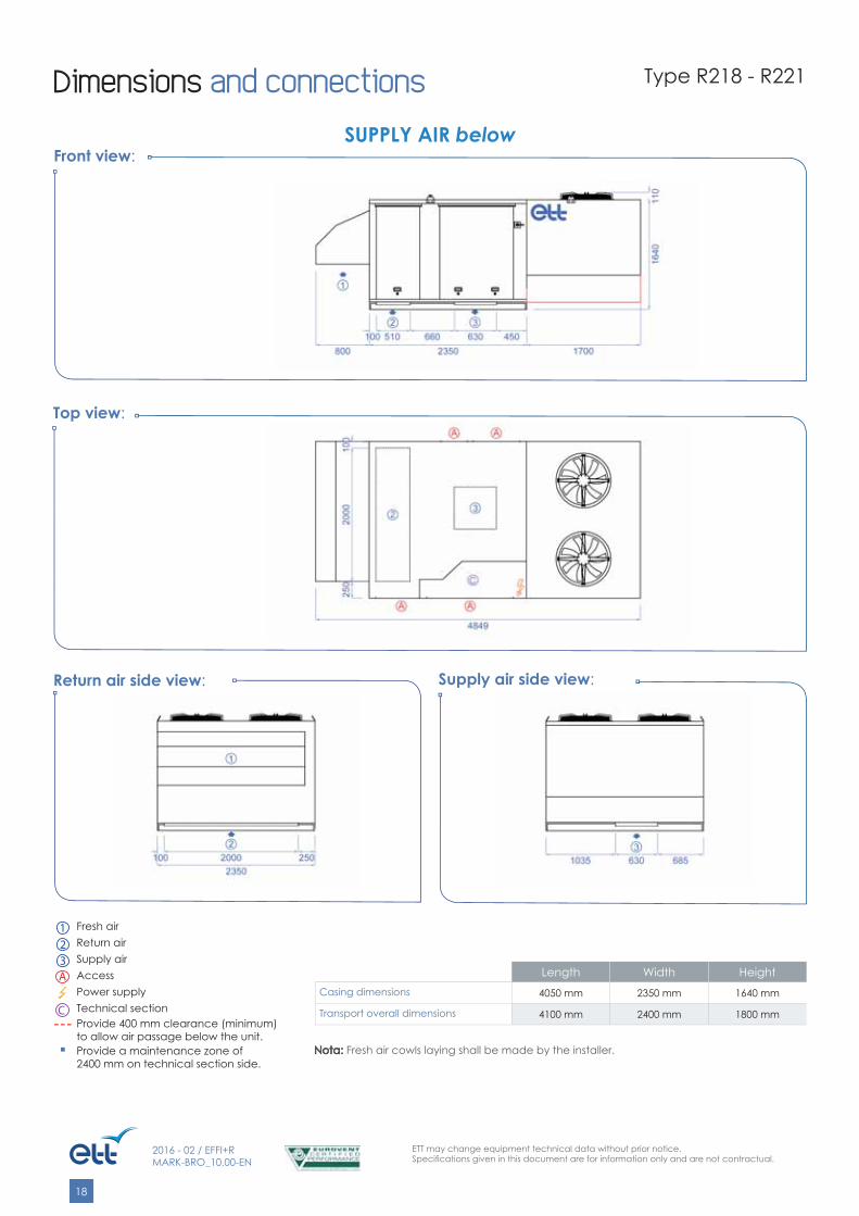
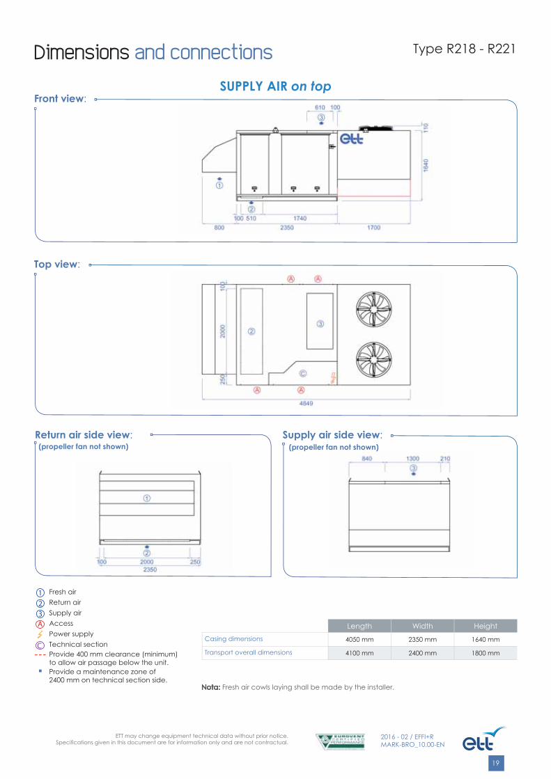
Dimensions and connections
Length Width HeightCasing dimensions 4050 mm 2350 mm 1640 mm
Transport overall dimensions 4100 mm 2400 mm 1800 mm
Type R218 - R221
Front view:
Top view:
Return air side view: Supply air side view:
SUPPLY AIR below
Nota:Nota: Fresh air cowls laying shall be made by the installer.
1 Fresh air
2 Return air3 Supply airA Access
Power supply
C Technical sectionProvide 400 mm clearance (minimum) to allow air passage below the unit.
■ Provide a maintenance zone of 2400 mm on technical section side.
ETT may change equipment technical data without prior notice.Specifi cations given in this document are for information only and are not contractual.
19
2016 - 02 / EFFI+RMARK-BRO_10.00-EN
Length Width HeightCasing dimensions 4050 mm 2350 mm 1640 mm
Transport overall dimensions 4100 mm 2400 mm 1800 mm
Front view:
Top view:
Return air side view: Supply air side view:
SUPPLY AIR on top
(propeller fan not shown) (propeller fan not shown)
Nota:Nota: Fresh air cowls laying shall be made by the installer.
Dimensions and connections Type R218 - R221
1 Fresh air
2 Return air3 Supply airA Access
Power supply
C Technical sectionProvide 400 mm clearance (minimum) to allow air passage below the unit.
■ Provide a maintenance zone of 2400 mm on technical section side.

ETT may change equipment technical data without prior notice.Specifi cations given in this document are for information only and are not contractual.
20
2016 - 02 / EFFI+RMARK-BRO_10.00-EN
Length Width HeightCasing dimensions 4050 mm 2350 mm 1640 mm
Transport overall dimensions 4100 mm 2525 mm 1800 mm
Front view:
Top view:
Return air side view: Supply air side view:
SUPPLY AIR on side
INSTALLER SUPPORT
Nota: Nota: - Fresh air cowls shall be fi tted by the installer.- Lateral box laying shall be made by the installer.- Supply air damper electrical connection shall be made by the installer.
Dimensions and connections Type R218 - R221
1 Fresh air
2 Return air3 Supply airA Access
Power supply
C Technical sectionProvide 400 mm clearance (minimum) to allow air passage below the unit.
■ Provide a maintenance zone of 2400 mm on technical section side.
ETT may change equipment technical data without prior notice.Specifi cations given in this document are for information only and are not contractual.
21
2016 - 02 / EFFI+RMARK-BRO_10.00-EN
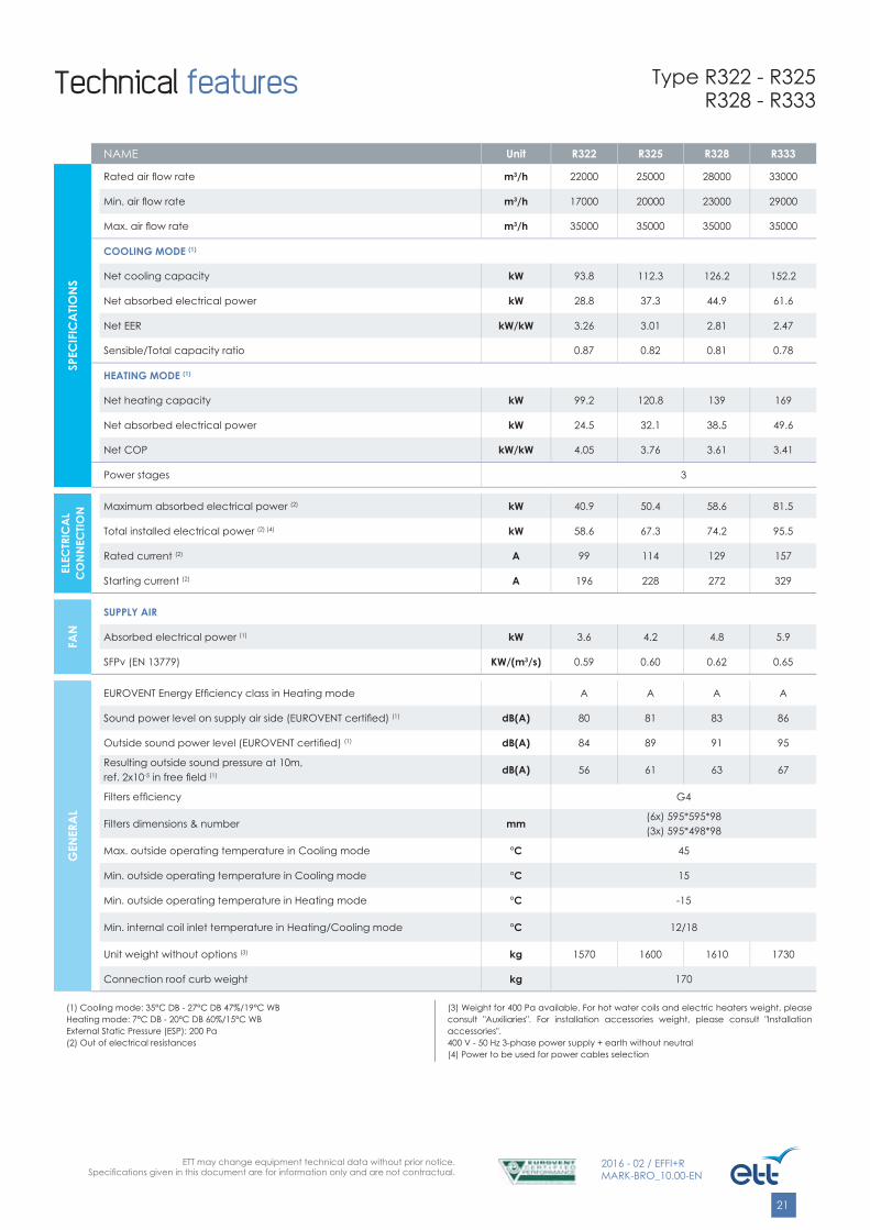
Technical features
NAME Unit R322 R325 R328 R333
SPEC
IFIC
ATIO
NS
Rated air fl ow rate m3/h 22000 25000 28000 33000
Min. air fl ow rate m3/h 17000 20000 23000 29000
Max. air fl ow rate m3/h 35000 35000 35000 35000
COOLING MODE (1)
Net cooling capacity kW 93.8 112.3 126.2 152.2
Net absorbed electrical power kW 28.8 37.3 44.9 61.6
Net EER kW/kW 3.26 3.01 2.81 2.47
Sensible/Total capacity ratio 0.87 0.82 0.81 0.78
HEATING MODE (1)
Net heating capacity kW 99.2 120.8 139 169
Net absorbed electrical power kW 24.5 32.1 38.5 49.6
Net COP kW/kW 4.05 3.76 3.61 3.41
Power stages 3
ELEC
TRIC
AL
CO
NN
ECTIO
N Maximum absorbed electrical power (2) kW 40.9 50.4 58.6 81.5
Total installed electrical power (2) (4) kW 58.6 67.3 74.2 95.5
Rated current (2) A 99 114 129 157
Starting current (2) A 196 228 272 329
FAN
SUPPLY AIR
Absorbed electrical power (1) kW 3.6 4.2 4.8 5.9
SFPv (EN 13779) KW/(m3/s) 0.59 0.60 0.62 0.65
GEN
ERA
L
EUROVENT Energy Effi ciency class in Heating mode A A A A
Sound power level on supply air side (EUROVENT certifi ed) (1) dB(A) 80 81 83 86
Outside sound power level (EUROVENT certifi ed) (1) dB(A) 84 89 91 95
Resulting outside sound pressure at 10m,ref. 2x10⁻⁵ in free fi eld (1) dB(A) 56 61 63 67
Filters effi ciency G4
Filters dimensions & number mm (6x) 595*595*98(3x) 595*498*98
Max. outside operating temperature in Cooling mode °C 45
Min. outside operating temperature in Cooling mode °C 15
Min. outside operating temperature in Heating mode °C -15
Min. internal coil inlet temperature in Heating/Cooling mode °C 12/18
Unit weight without options (3) kg 1570 1600 1610 1730
Connection roof curb weight kg 170
(1) Cooling mode: 35°C DB - 27°C DB 47%/19°C WBHeating mode: 7°C DB - 20°C DB 60%/15°C WBExternal Static Pressure (ESP): 200 Pa(2) Out of electrical resistances
(3) Weight for 400 Pa available. For hot water coils and electric heaters weight, please consult "Auxiliaries". For installation accessories weight, please consult "Installation accessories".400 V - 50 Hz 3-phase power supply + earth without neutral(4) Power to be used for power cables selection
Type R322 - R325R328 - R333

ETT may change equipment technical data without prior notice.Specifi cations given in this document are for information only and are not contractual.
22
2016 - 02 / EFFI+RMARK-BRO_10.00-EN
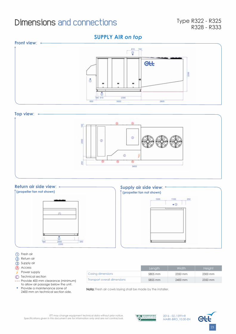
Dimensions and connections
Length Width HeightCasing dimensions 5805 mm 2350 mm 2300 mm
Transport overall dimensions 5855 mm 2400 mm 2350 mm
Front view:
Top view:
Return air side view: Supply air side view:
SUPPLY AIR below
Nota:Nota: Fresh air cowls laying shall be made by the installer.
Type R322 - R325R328 - R333
1 Fresh air
2 Return air3 Supply airA Access
Power supply
C Technical sectionProvide 400 mm clearance (minimum) to allow air passage below the unit.
■ Provide a maintenance zone of 2400 mm on technical section side.
ETT may change equipment technical data without prior notice.Specifi cations given in this document are for information only and are not contractual.
23
2016 - 02 / EFFI+RMARK-BRO_10.00-EN
Length Width HeightCasing dimensions 5805 mm 2350 mm 2300 mm
Transport overall dimensions 5855 mm 2400 mm 2350 mm
Front view:
Top view:
Return air side view: Supply air side view:
SUPPLY AIR on top
(propeller fan not shown) (propeller fan not shown)
Nota:Nota: Fresh air cowls laying shall be made by the installer.
Dimensions and connections Type R322 - R325R328 - R333
1 Fresh air
2 Return air3 Supply airA Access
Power supply
C Technical sectionProvide 400 mm clearance (minimum) to allow air passage below the unit.
■ Provide a maintenance zone of 2400 mm on technical section side.

ETT may change equipment technical data without prior notice.Specifi cations given in this document are for information only and are not contractual.
24
2016 - 02 / EFFI+RMARK-BRO_10.00-EN
Length Width HeightCasing dimensions 5805 mm 2350 mm 2300 mm
Transport overall dimensions 5855 mm 2525 mm 2350 mm
Front view:
Top view:
Return air side view: Supply air side view:
SUPPLY AIR on side
INSTALLER SUPPORT
Nota: Nota: - Fresh air cowls shall be fi tted by the installer.- Lateral box laying shall be made by the installer.- Supply air damper electrical connection shall be made by the installer.
Dimensions and connections Type R322 - R325R328 - R333
1 Fresh air
2 Return air3 Supply airA Access
Power supply
C Technical sectionProvide 400 mm clearance (minimum) to allow air passage below the unit.
■ Provide a maintenance zone of 2400 mm on technical section side.

ETT may change equipment technical data without prior notice.Specifi cations given in this document are for information only and are not contractual.
25
2016 - 02 / EFFI+RMARK-BRO_10.00-EN
SUPPLY AIR downwards, upwards and on sideInstallation on roof curb or customer frame on roof.
Arrangements
Arrangement 1.1
1
2 3
Arrangement 2.1
1
3
2
Arrangement 3.1
2
3
1
1 Fresh air 2 Return air 3 Supply air
ETT may change equipment technical data without prior notice.Specifi cations given in this document are for information only and are not contractual.
26
2016 - 02 / EFFI+RMARK-BRO_10.00-EN
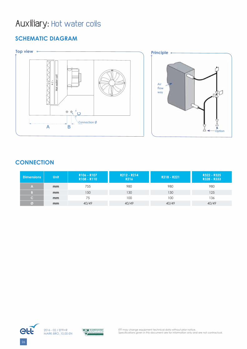
Top view Principle
Dimensions Unit R106 - R107R108 - R110
R212 - R214R216 R218 - R221 R322 - R325
R328 - R333
A mm 755 980 980 980
B mm 150 130 130 125C mm 75 100 100 136Ø mm 40/49 40/49 40/49 40/49
Auxiliary: Hot water coils
SCHEMATIC DIAGRAM
CONNECTION
+ / -
BE
C
Ø de raccordement
A B
C
Connec� on Ø
Op� on
Air fl ow way
Hot w
ater
coi
l

ETT may change equipment technical data without prior notice.Specifi cations given in this document are for information only and are not contractual.
27
2016 - 02 / EFFI+RMARK-BRO_10.00-EN
Unit R106 R107 R108 R110 R212 R214 R216
Water regime90/70°C
Capacity kW 92 107 117 134 172 191 208
Flow rate m3/h 4.1 4.7 5.1 5.9 7.6 8.4 9.2
3WV + coil pressure drop mWC 2.5 3.5 4.3 5.3 3.1 4.2 4.8
Water regime90/70°C
Stop and TA valves pressure drop(opened by 3 turns)
mWC 1.1 1.5 1.8 2.3 1.3 1.6 1.9
Unit R218 R221 R322 R325 R328 R333
Water regime90/70°C
Capacity kW 187 206 162 177 191 213
Flow rate m3/h 8.2 9.1 7.2 7.8 8.4 9.4
3WV + coil pressure drop mWC 4.0 4.8 4.7 5.6 4.2 5.2
Water regime90/70°C
Stop and TA valves pressure drop(opened by 3 turns)
mWC 1.6 1.9 1.2 1.4 1.6 2.0
CAPACITIES
Auxiliary: Hot water coils
With 10°C air inlet temperature on coils
ETT may change equipment technical data without prior notice.Specifi cations given in this document are for information only and are not contractual.
28
2016 - 02 / EFFI+RMARK-BRO_10.00-EN
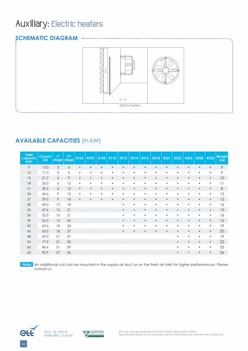
Total capacity
(kW)Current
(A)1st
stage 2nd
stage R106 R107 R108 R110 R212 R214 R216 R218 R221 R322 R325 R328 R333 Weight (kg)
9 13.0 3 6 • • • • • • • • • • • • • 9 12 17.3 3 9 • • • • • • • • • • • • • 915 21.7 6 9 • • • • • • • • • • • • • 1018 26.0 6 12 • • • • • • • • • • • • • 1121 30.3 6 15 • • • • • • • • • • • • • 824 34.6 9 15 • • • • • • • • • • • • • 1227 39.0 9 18 • • • • • • • • • • • • • 1530 43.3 12 18 • • • • • • • • • 1633 47.6 12 21 • • • • • • • • • 1536 52.0 15 21 • • • • • • • • • 1639 56.3 15 24 • • • • • • • • • 1642 60.6 18 24 • • • • • • • • • 1945 65.0 18 27 • • • • • • • • • 2048 69.3 21 27 • • • • 1954 77.9 21 33 • • • • 2260 86.6 21 39 • • • • 2363 90.9 27 36 • • • • 26
AVAILABLE CAPACITIES (in kW)
Auxiliary: Electric heaters
SCHEMATIC DIAGRAM
+ / -
Batteries électriquesElectric heaters
An additional coil can be mounted in the supply air duct or on the fresh air inlet for higher performances. Please consult us.
Nota:

ETT may change equipment technical data without prior notice.Specifi cations given in this document are for information only and are not contractual.
29
2016 - 02 / EFFI+RMARK-BRO_10.00-EN
G
C H
F
Dimensions Unit R106 - R107 R108 - R110
R212 - R214R216 R218 - R221 R322 - R325
R328 - R333A mm 153 200 236 270
B mm 469 483 498 492
C mm 241 293 331 355
D mm 400 500 600 600
E mm 850 750 850 850
F mm 1500 1330 1640 2300
G mm 1480 1180 1490 2063
H mm 1600 2350 2350 2350
Ø mm 50 x 60 50 x 60 66 x 76 66 x 76
Top view Side view
Preheating: Water recovery coils
SCHEMATIC DIAGRAM
CONNECTION
+ / -
RE
CU
P
Ø de raccordementB A
ED
Connec� on Ø
RECO
VERY

ETT may change equipment technical data without prior notice.Specifi cations given in this document are for information only and are not contractual.
30
2016 - 02 / EFFI+RMARK-BRO_10.00-EN
Preheating: Water recovery coils
CAPACITIES
Unit R106 R107 R108 R110 R212 R214 R216 R218 R221
Water regime35/30°C
Air inlet+10°C/70%
Capacity kW 28.9 33.7 36.7 42.1 54.1 60 65.4 77.8 86.1
Flow rate m3/h 5.0 5.8 6.4 7.3 9.4 10.4 11.3 13.5 14.9
Valves (3WV + TA)+ coil pressure drop mWC 2.8 3.5 4.4 5.4 4.6 5.3 6.3 3 3.7
Supply air temperatureat coil outlet °C 23.9 23.0 22.4 21.6 23.0 22.4 21.8 22.5 21.8
Water regime35/30°C
Air inlet+20°C/50%
Capacity kW 15 17.4 18.9 21.6 27.8 30.8 33.5 39.9 44
Flow rate m3/h 2.6 3.0 3.3 3.7 4.8 5.3 5.8 6.9 7.6
Valves (3WV + TA)+ coil pressure drop mWC 1.0 1.1 1.3 1.7 1.4 1.7 1.8 1.0 1.2
Supply air temperatureat coil outlet °C 27.5 26.9 26.6 26.1 26.9 26.6 26.2 26.6 26.3
Unit R322 R325 R328 R333
Water regime35/30°C
Air inlet+10°C/70%
Capacity kW 101 110 119 132
Flow rate m3/h 17.5 19.1 20.6 22.9
Valves (3WV + TA)+ coil pressure drop mWC 4.1 4.5 5.5 6.6
Supply air temperatureat coil outlet °C 23.3 22.7 22.3 21.6
Water regime35/30°C
Air inlet+20°C/50%
Capacity kW 52.1 56.7 61 67.6
Flow rate m3/h 9.0 9.8 10.6 11.7
Valves (3WV + TA)+ coil pressure drop mWC 1.3 1.4 1.6 2.0
Supply air temperatureat coil outlet °C 27.1 26.8 26.5 26.1
ETT may change equipment technical data without prior notice.Specifi cations given in this document are for information only and are not contractual.
31
2016 - 02 / EFFI+RMARK-BRO_10.00-EN
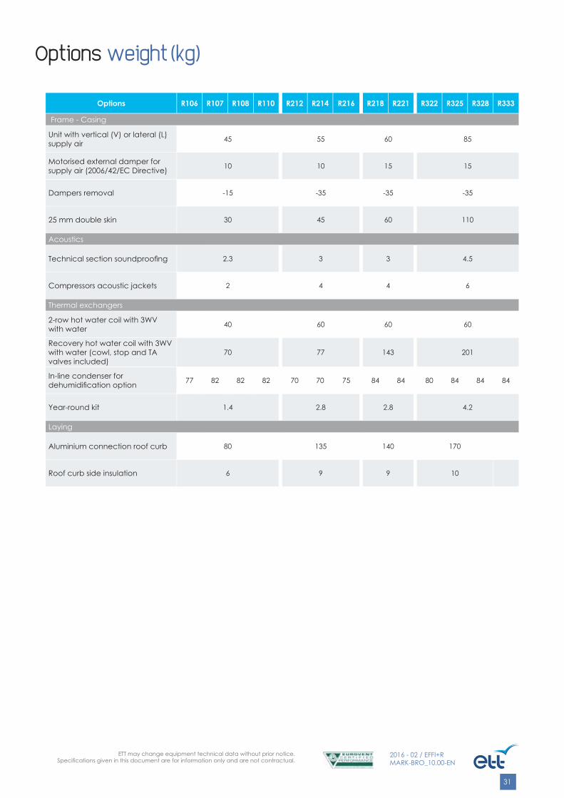
Options weight (kg)
Options R106 R107 R108 R110 R212 R214 R216 R218 R221 R322 R325 R328 R333
Frame - Casing
Unit with vertical (V) or lateral (L) supply air 45 55 60 85
Motorised external damper for supply air (2006/42/EC Directive) 10 10 15 15
Dampers removal -15 -35 -35 -35
25 mm double skin 30 45 60 110
Acoustics
Technical section soundproofi ng 2.3 3 3 4.5
Compressors acoustic jackets 2 4 4 6
Thermal exchangers
2-row hot water coil with 3WV with water 40 60 60 60
Recovery hot water coil with 3WV with water (cowl, stop and TA valves included)
70 77 143 201
In-line condenser for dehumidifi cation option 77 82 82 82 70 70 75 84 84 80 84 84 84
Year-round kit 1.4 2.8 2.8 4.2
Laying
Aluminium connection roof curb 80 135 140 170
Roof curb side insulation 6 9 9 10
ETT may change equipment technical data without prior notice.Specifi cations given in this document are for information only and are not contractual.
32
2016 - 02 / EFFI+RMARK-BRO_10.00-EN
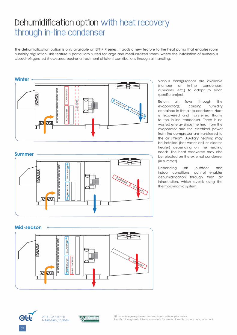
Dehumidifi cation option with heat recoverythrough in-line condenser
The dehumidifi cation option is only available on EFFI+ R series. It adds a new feature to the heat pump that enables room humidity regulation. This feature is particularly suited for large and medium-sized stores, where the installation of numerous closed refrigerated showcases requires a treatment of latent contributions through air handling.
Various confi gurations are available (number of in-line condensers, auxiliaries, etc.) to adapt to each specifi c project.
Return air fl ows through the evaporator(s), causing humidity contained in the air to condense. Heat is recovered and transferred thanks to the in-line condenser. There is no wasted energy since the heat from the evaporator and the electrical power from the compressor are transferred to the air stream. Auxiliary heating may be installed (hot water coil or electric heater) depending on the heating needs. The heat recovered may also be rejected on the external condenser (in summer).
Depending on outdoor and indoor conditions, control enables dehumidifi cation through fresh air introduction, which avoids using the thermodynamic system.
Winter
Summer
Mid-season
EVAPORATOR
CO
ND
ENSE
R AUX
ILIA
RIES
IN-L
INE
CO
NDEN
SER
CONDENSER
CO
ND
ENSE
R
CONDENSER
EVA
PORA
TOR
EVA
PORA
TOR
EVA
PORA
TOR
EVA
PORA
TOR
EVAPORATOR
CONDENSER

ETT may change equipment technical data without prior notice.Specifi cations given in this document are for information only and are not contractual.
33
2016 - 02 / EFFI+RMARK-BRO_10.00-EN
Dehumidifi cation option with heat recoverythrough in-line condenser
NAME Unit R106 R107 R108 R110 R212 R214 R216
RETURN AIR CONDITIONS IN COOLING MODE26°C/50% RH
Dehumidifi cation capacity L/h 18 20 21 26 28 31 34
In-line circuit recovery capacity kW 40 50.7 58.7 73.2 35.3 41.2 50.8
RETURN AIR CONDITIONS IN HEATING MODE20°C/50% RH
Dehumidifi cation capacity L/h 13 14 15 18 19 20 24
In-line circuit recovery capacity kW 35.6 45.4 52.8 65.9 31.6 36.8 45.5
Number of available in-line circuits 1 1
NAME Unit R218 R221 R322 R325 R328 R333
RETURN AIR CONDITIONS IN COOLING MODE26°C/50% RH
Dehumidifi cation capacity L/h 46 52.2 51.9 62 67 76
In-line circuit recovery capacity kW 59.8 74.9 41.6 51.8 60.0 75.6
RETURN AIR CONDITIONS IN HEATING MODE20°C/50% RH
Dehumidifi cation capacity L/h 31 37.6 35.4 42 47 58
In-line circuit recovery capacity kW 53.5 67.6 37.1 46.3 53.7 67.7
Number of available in-line circuits 1 2

ETT may change equipment technical data without prior notice.Specifi cations given in this document are for information only and are not contractual.
34
2016 - 02 / EFFI+RMARK-BRO_10.00-EN
Dehumidifi cation option with heat recoverythrough in-line condenser
Level 1: Dehumidifi cation without energy recovery. The refrigeration circuit features a year-round kit in order to enable dehumidifi cation operation in winter. Heat is evacuated through the external condenser. An auxiliary electric heater or hot water coil must be installed in order to ensure suffi cient supply air conditions.
OPTION LEVELS PER CIRCUIT
AVAILABLE CONFIGURATIONS
Unit R106 - R107 R108 - R110
R212 - R214R216 R218 - R221 R322 - R325
R328 - R333
Level 1 1 2 2 3
Level 2 1 1 1 2
Level 3 1 1 1 2
EXAMPLE OF SELECTION
EFFI+ R325, all 3 circuits are equipped with dehumidifi cation option for maximum dehumidifi cation capacity (58 L/h in Heating mode with 20°C/50% RH return air conditions). 2 circuits are equipped with an in-line condenser to maximise energy recovery (92.6 kW in Heating mode with 20°C/50% RH return air conditions)Circuit 1: Level 2 (energy recovery)Circuit 2: Level 3 (energy recovery and supply air temperature control)Circuit 3: Level 12 hygrometry probes are supplied (internal and external). The installer is in charge of connecting the internal probe and shall supply and install the connecting cable for master/slave operation with other units.
Level 2: Dehumidifi cation with energy recovery through in-line condenser, on/off refrigeration 3-way valve and year-round kit. The heat recovered is transferred either to the air stream or to the external condenser depending on the season or on the supply air temperature setpoint. An additional auxiliary heater may be installed for winter operation, depending on project characteristics.
Level 3:Dehumidifi cation with energy recovery through in-line condenser, analogue refrigeration 3-way valve and year-round kit. Supply air temperature control: When supply air temperature is reached, excess heat is evacuated through the external condenser. An additional auxiliary heater may be installed for winter operation, depending on project characteristics.
ETT may change equipment technical data without prior notice.Specifi cations given in this document are for information only and are not contractual.
35
2016 - 02 / EFFI+RMARK-BRO_10.00-EN
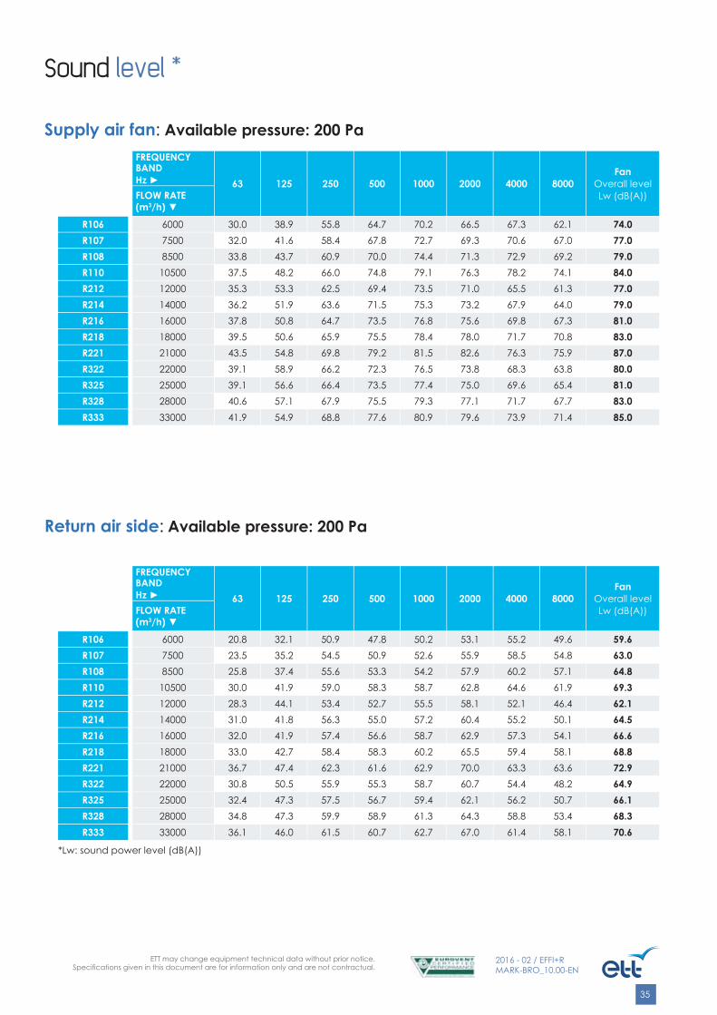
Supply air fan: Available pressure: 200 Pa
Return air side: Available pressure: 200 Pa
FREQUENCYBANDHz ► 63 125 250 500 1000 2000 4000 8000
FanOverall levelLw (dB(A))FLOW RATE
(m3/h) ▼
R106 6000 20.8 32.1 50.9 47.8 50.2 53.1 55.2 49.6 59.6R107 7500 23.5 35.2 54.5 50.9 52.6 55.9 58.5 54.8 63.0R108 8500 25.8 37.4 55.6 53.3 54.2 57.9 60.2 57.1 64.8R110 10500 30.0 41.9 59.0 58.3 58.7 62.8 64.6 61.9 69.3R212 12000 28.3 44.1 53.4 52.7 55.5 58.1 52.1 46.4 62.1R214 14000 31.0 41.8 56.3 55.0 57.2 60.4 55.2 50.1 64.5R216 16000 32.0 41.9 57.4 56.6 58.7 62.9 57.3 54.1 66.6R218 18000 33.0 42.7 58.4 58.3 60.2 65.5 59.4 58.1 68.8R221 21000 36.7 47.4 62.3 61.6 62.9 70.0 63.3 63.6 72.9R322 22000 30.8 50.5 55.9 55.3 58.7 60.7 54.4 48.2 64.9R325 25000 32.4 47.3 57.5 56.7 59.4 62.1 56.2 50.7 66.1R328 28000 34.8 47.3 59.9 58.9 61.3 64.3 58.8 53.4 68.3R333 33000 36.1 46.0 61.5 60.7 62.7 67.0 61.4 58.1 70.6
*Lw: sound power level (dB(A))
FREQUENCYBANDHz ► 63 125 250 500 1000 2000 4000 8000
FanOverall levelLw (dB(A))FLOW RATE
(m3/h) ▼
R106 6000 30.0 38.9 55.8 64.7 70.2 66.5 67.3 62.1 74.0R107 7500 32.0 41.6 58.4 67.8 72.7 69.3 70.6 67.0 77.0R108 8500 33.8 43.7 60.9 70.0 74.4 71.3 72.9 69.2 79.0R110 10500 37.5 48.2 66.0 74.8 79.1 76.3 78.2 74.1 84.0R212 12000 35.3 53.3 62.5 69.4 73.5 71.0 65.5 61.3 77.0R214 14000 36.2 51.9 63.6 71.5 75.3 73.2 67.9 64.0 79.0R216 16000 37.8 50.8 64.7 73.5 76.8 75.6 69.8 67.3 81.0R218 18000 39.5 50.6 65.9 75.5 78.4 78.0 71.7 70.8 83.0R221 21000 43.5 54.8 69.8 79.2 81.5 82.6 76.3 75.9 87.0R322 22000 39.1 58.9 66.2 72.3 76.5 73.8 68.3 63.8 80.0R325 25000 39.1 56.6 66.4 73.5 77.4 75.0 69.6 65.4 81.0R328 28000 40.6 57.1 67.9 75.5 79.3 77.1 71.7 67.7 83.0R333 33000 41.9 54.9 68.8 77.6 80.9 79.6 73.9 71.4 85.0
Sound level *

ETT may change equipment technical data without prior notice.Specifi cations given in this document are for information only and are not contractual.
36
2016 - 02 / EFFI+RMARK-BRO_10.00-EN
SERIES 1 (R106 - R107 - R108 - R110)
Previous range (before 2004) EFFI+ R
S1
Dimensions Unit 22 - 25 - 32 37 R106 - R107 - R108 - R110A mm 2550 2860 2800B mm 1600 1600
H mm 1200 1500L mm 1600 1600
C mm 310 310
G mm 1200 1200
E mm 410 410
K mm 472 470D mm 530 530
J mm 364 364
Q mm 600 750
2
3
3
100
G
A
J
K
L
JK
3
3
2
Top view Supply air side view
1
1
32 2
H
100 C ED
L
100 G
B
Q
1
2 3
1
2
Side view Fresh air side view
1 Fresh air2 Return air3 Supply air
Compatibility with previous range
ETT may change equipment technical data without prior notice.Specifi cations given in this document are for information only and are not contractual.
37
2016 - 02 / EFFI+RMARK-BRO_10.00-EN
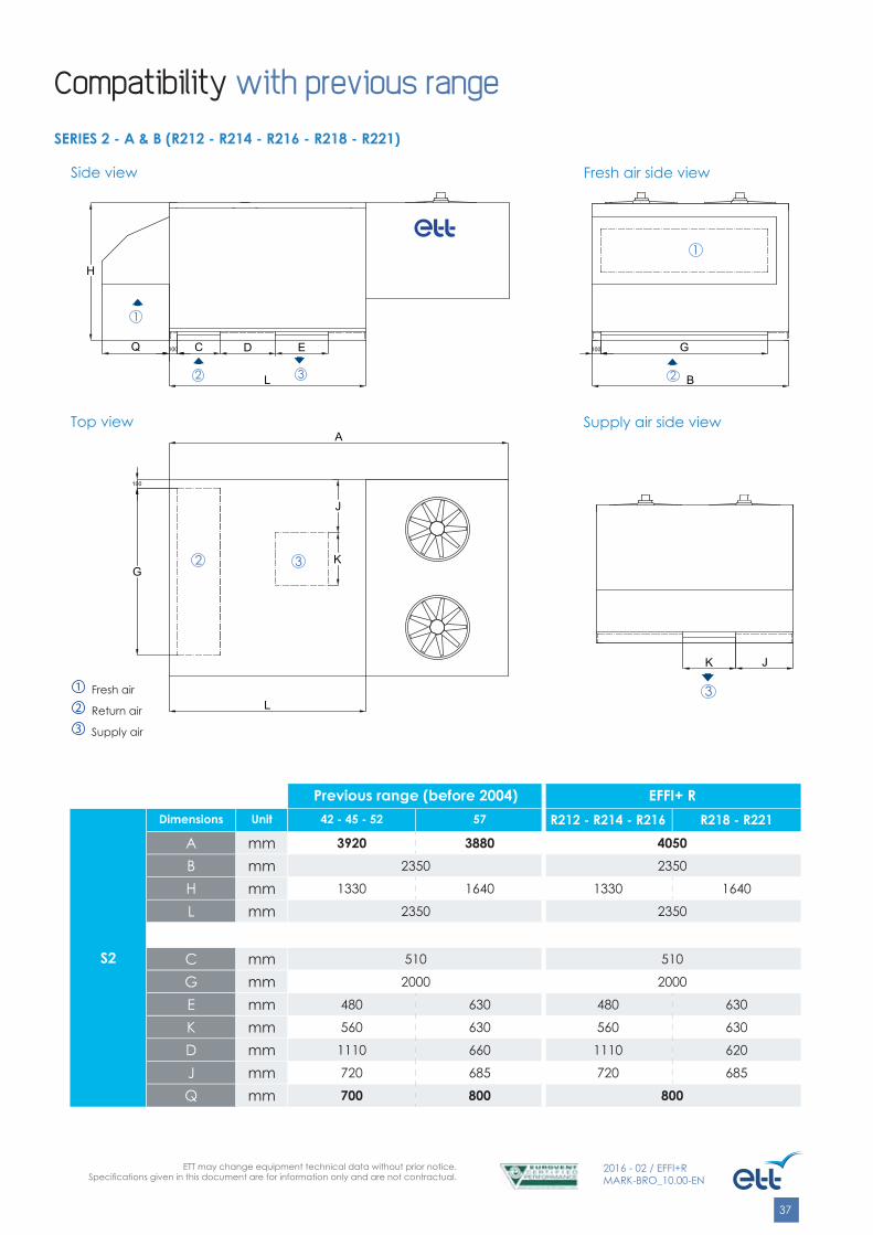
SERIES 2 - A & B (R212 - R214 - R216 - R218 - R221)
Previous range (before 2004) EFFI+ R
S2
Dimensions Unit 42 - 45 - 52 57 R212 - R214 - R216 R218 - R221
A mm 3920 3880 4050B mm 2350 2350
H mm 1330 1640 1330 1640
L mm 2350 2350
C mm 510 510
G mm 2000 2000
E mm 480 630 480 630
K mm 560 630 560 630
D mm 1110 660 1110 620
J mm 720 685 720 685
Q mm 700 800 800
2
3
3
100
G
A
J
K
L
JK
32
3
Top view Supply air side view
1
1
32 2
H
100 C ED
L
100 G
B
Q
1
2 3
1
2
Side view Fresh air side view
Compatibility with previous range
1 Fresh air2 Return air3 Supply air

ETT may change equipment technical data without prior notice.Specifi cations given in this document are for information only and are not contractual.
38
2016 - 02 / EFFI+RMARK-BRO_10.00-EN
SERIES 3 (R322 - R325 - R328 - R333)
Previous range (before 2004) EFFI+ R
S3
Dimensions Unit 62 - 65 - 72 77 R322 - R325 - R328 - R333A mm 5070 5175 5805B mm 2350 2350
H mm 1900 2300 2300L mm 3000 3000
C mm 510 510
G mm 2000 2000
E mm 800 800
K mm 800 800
D mm 1440 1440
J mm 425 425
Q mm 900 650
2
3
3
100
G
A
J
K
L
JK
32
3
Top view Supply air side view
1
1
32 2
H
100 C ED
L
100 G
B
Q
1
2 3
1
2
Side view Fresh air side view
Compatibility with previous range
1 Fresh air2 Return air3 Supply air

ETT may change equipment technical data without prior notice.Specifi cations given in this document are for information only and are not contractual.
39
2016 - 02 / EFFI+RMARK-BRO_10.00-EN
With an existing ETT unit (PAC 22, 25, 32, 37, 42, 45, 52 and 57 IROISE)ETT equipment is designed for standard replacement.
With an existing ETT unit (PAC 62, 65, 72, 77)Please consult the factory as the arrangements depend on the manufacturing date.
With another existing unitA bespoke adapter interface is to be installed.
Adaptation roof curb
Installation accessories: Roof curbs

ETT may change equipment technical data without prior notice.Specifi cations given in this document are for information only and are not contractual.
40
2016 - 02 / EFFI+RMARK-BRO_10.00-EN
Roof curbs are intended for steel decks up to 145 mm high and insulation up to 200 mm high (i.e. max. H=345 mm).
Installation accessories: Roof curbs
Roof curbs installation principle
One (for connection roof curb) or two (for ventilated roof curb) optional cover sheets can be added to protect the building from the weather during the time between roof curb laying and unit laying.
Nota:
50
100
Binding joist
Optional: side insulation
Connection roof curb
Unit frame
Waterproofi ng membrane
Sealant gasket between the frame and the roof curb on the periphery
Steel deck
InsulationH
150
min
.
600
(or 6
50 a
ccor
ding
to th
e un
it)
Outer insulation shall be part of the waterproofi ng package (not supplied by ETT)

ETT may change equipment technical data without prior notice.Specifi cations given in this document are for information only and are not contractual.
41
2016 - 02 / EFFI+RMARK-BRO_10.00-EN
Unit 106 108 109 110 112 213 215 217 218 220 222 323 326 330 333
Nr. of feet 4 4 4 4 4 4 4 4 4 4 4 4 4 4 4
Aluminium fi xed footUnitary weight: 1 kg
Installation accessories: Feet
ETT may change equipment technical data without prior notice.Specifi cations given in this document are for information only and are not contractual.
42
2016 - 02 / EFFI+RMARK-BRO_10.00-EN
3
2
1
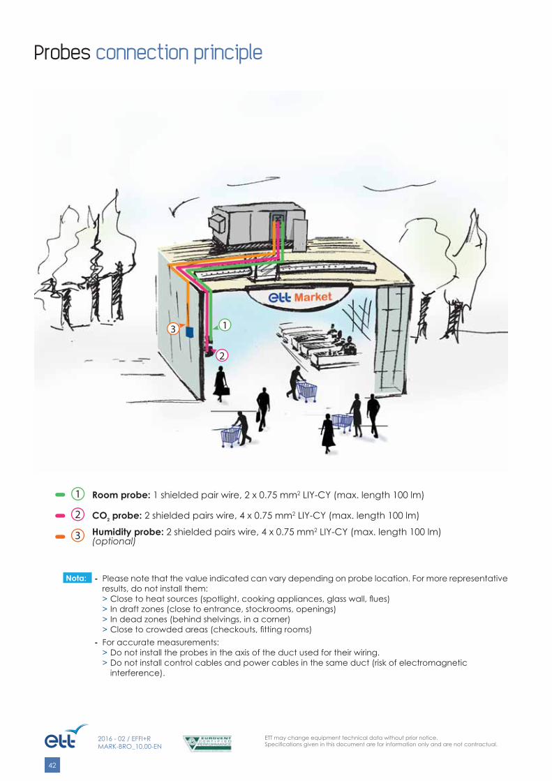
Probes connection principle
1 Room probe: 1 shielded pair wire, 2 x 0.75 mm2 LIY-CY (max. length 100 lm)
2 CO2 probe: 2 shielded pairs wire, 4 x 0.75 mm2 LIY-CY (max. length 100 lm)
3 Humidity probe: 2 shielded pairs wire, 4 x 0.75 mm2 LIY-CY (max. length 100 lm)(optional)
- Please note that the value indicated can vary depending on probe location. For more representative results, do not install them:> Close to heat sources (spotlight, cooking appliances, glass wall, fl ues)> In draft zones (close to entrance, stockrooms, openings)> In dead zones (behind shelvings, in a corner)> Close to crowded areas (checkouts, fi tting rooms)
- For accurate measurements:> Do not install the probes in the axis of the duct used for their wiring.> Do not install control cables and power cables in the same duct (risk of electromagnetic
interference).
Nota:

Des
ign:
ETT
- D
ocum
ent p
rinte
d b
y an
env
ironm
enta
lly fr
iend
ly p
rinte
r usin
g ve
geta
ble
base
d in
k on
PEF
C p
aper
cre
ated
from
sust
aina
bly-
man
aged
fore
st.
www.ett.fr
ETT - Route de Brest - BP2629830 Ploudalmézeau - FranceTel: +33 (0)2 98 48 14 22Fax: +33 (0)2 98 48 09 12Export Contact: +33 (0)2 98 48 00 70ETT Services: +33 (0) 2 98 48 02 22
Reference: MARK-BRO_10.00-EN