efis-d10a › public_html › yabbfiles › ...the efis-d10a uses solid-state sensor technology to...
TRANSCRIPT

EFIS-D10A
Installation Guide
This product is intended for the experimental and Light Sport aircraft categories and is not approved for installation in type certificated aircraft
Revision prelim July 11, 2007
Copyright © 2007 by Dynon Avionics


Contact Information Dynon Avionics, Inc. 19825 141st Place NE Woodinville, WA 98072 Phone: (425) 402-0433 Fax: (425) 984-1751 www.dynonavionics.com
Copyright © 2007 Dynon Avionics. All rights reserved. No part of this manual may be reproduced, copied, transmitted, disseminated or stored in any storage medium, for any purpose without the express written permission of Dynon Avionics. Dynon Avionics hereby grants permission to download a single copy of this manual and of any revision to this manual onto a hard drive or other electronic storage medium to be viewed for personal use, provided that such electronic or printed copy of this manual or revision must contain the complete text of this copyright notice and provided further that any unauthorized commercial distribution of this manual or any revision hereto is strictly prohibited.
Information in this document is subject to change without notice. Dynon Avionics reserves the right to change or improve its products and to make changes in the content without obligation to notify any person or organization of such changes. Visit the Dynon Avionics website (www.DynonAvionics.com) for current updates and supplemental information concerning the use and operation of this and other Dynon Avionics products.
Limited Warranty Dynon Avionics warrants this product to be free from defects in materials and workmanship for three years from date of shipment. Dynon Avionics will, at its sole option, repair or replace any components that fail in normal use. Such repairs or replacement will be made at no charge to the customer for parts or labor. The customer is, however, responsible for any transportation cost. This warranty does not cover failures due to abuse, misuse, accident, improper installation or unauthorized alteration or repairs.
THE WARRANTIES AND REMEDIES CONTAINED HEREIN ARE EXCLUSIVE, AND IN LIEU OF ALL OTHER WARRANTIES EXPRESSED OR IMPLIED, INCLUDING ANY LIABILITY ARISING UNDER WARRANTY OF MERCHANTABILITY OR FITNESS FOR A PARTICULAR PURPOSE, STATUTORY OR OTHERWISE. THIS WARRANTY GIVES YOU SPECIFIC LEGAL RIGHTS, WHICH MAY VARY FROM STATE TO STATE.
IN NO EVENT SHALL DYNON AVIONICS BE LIABLE FOR ANY INCIDENTAL, SPECIAL, INDIRECT OR CONSEQUENTIAL DAMAGES, WHETHER RESULTING FROM THE USE, MISUSE OR INABILITY TO USE THIS PRODUCT OR FROM DEFECTS IN THE PRODUCT. SOME STATES DO NOT ALLOW THE EXCLUSION OF INCIDENTAL OR CONSEQUENTIAL DAMAGES, SO THE ABOVE LIMITATIONS MAY NOT APPLY TO YOU.
Dynon Avionics retains the exclusive right to repair or replace the instrument or firmware or offer a full refund of the purchase price at its sole discretion. SUCH REMEDY SHALL BE YOUR SOLE AND EXCLUSIVE REMEDY FOR ANY BREACH OF WARRANTY.
These instruments are intended for experimental and Light Sport aircraft only at this time. Dynon Avionics makes no claim as to the suitability of its products in connection with FAR 91.205.
Dynon Avionics’ products incorporate a variety of precise, calibrated electronics. Except for replacing the optional internal backup battery in EFIS-based products per the installation guide, our products do not contain any field/user-serviceable parts. Units that have been found to have been taken apart may not be eligible for repair under warranty. Additionally, once a Dynon Avionics unit is opened up, it will require calibration and verification at our Woodinville, WA offices before it can be considered airworthy.

EFIS-D10A Installation Guide v
Table of Contents
Contact Information......................................................................................................................................................iii Copyright......................................................................................................................................................................iii Limited Warranty .........................................................................................................................................................iii 1. Introduction 1-1 OEM Installations...................................................................................................................................................... 1-1 Warning ..................................................................................................................................................................... 1-1 About this Guide........................................................................................................................................................ 1-1 Menu Descriptions..................................................................................................................................................... 1-2 2. Wiring Overview 2-1 Recommended Wiring Practices................................................................................................................................ 2-1 Power Requirements.................................................................................................................................................. 2-1 25-Pin Female EFIS Harness..................................................................................................................................... 2-2 3. Instrument Installation 3-1 Selecting a Remote Compass Module Location ........................................................................................................ 3-1 EDC-D10A Communication Cable ........................................................................................................................... 3-2 Power Inputs.............................................................................................................................................................. 3-3 Serial Communication Cable..................................................................................................................................... 3-4 SL30 and/or GPS connection..................................................................................................................................... 3-5 Altitude Encoder Wiring ........................................................................................................................................... 3-8 Audio Alert Output...................................................................................................................................................3-10 Dynon Smart Avionics Bus (DSAB) Wiring............................................................................................................3-11 Panel Location and Mounting...................................................................................................................................3-12 Connecting Static & Pitot Lines ...............................................................................................................................3-14 4. EFIS Calibration and Configuration 4-1 Ensuring Proper Installation ...................................................................................................................................... 4-1 Setting Zero Pitch (In flight)...................................................................................................................................... 4-1 Compass Heading Calibration ................................................................................................................................... 4-1 Configure Airspeed Color Thresholds....................................................................................................................... 4-7 5. DSAB Configuration 5-1 Network Concepts ..................................................................................................................................................... 5-1 Example Networks .................................................................................................................................................... 5-1 Initial Setup ............................................................................................................................................................... 5-4 Network Status .......................................................................................................................................................... 5-5 6. Appendix 6-1 Appendix A: Instructions for Continued Airworthiness ............................................................................................ 6-1 Appendix B: Dynon OAT Probe Installation and Usage........................................................................................... 6-7 Appendix C: HS34 Installation and Configuration...................................................................................................6-10 Appendix D: Dynon AOA/Pitot Installation and Calibration ...................................................................................6-21 Appendix E: Encoder Serial-to-Gray Code Converter Installation...........................................................................6-29 Appendix F: Replacing the EFIS-D10A battery pack ..............................................................................................6-32 Appendix G: Weights ...............................................................................................................................................6-33 Appendix H: EFIS-D10A Specifications..................................................................................................................6-33


1. INTRODUCTION
This manual provides information about the physical, electrical, and plumbing installation of the EFIS-D10A, EDC-D10A and optional AOA pitot probe purchased from Dynon Avionics. Additionally, this guide deals with setting up the installation-dependant firmware options. Because you may not have purchased all the components, you need only read through the relevant sections of this guide. Information about the operation of this instrument can be found in the EFIS-D10A Pilot’s User Guide.
The EFIS-D10A uses solid-state sensor technology to give an accurate and easy-to-understand display. To ensure accuracy in its readings, it is very important that you install the instrument correctly and perform the specified calibration steps. This installation guide will help you through that process.
OEM Installations If your EFIS-D10A is installed by an OEM distributor, you may find that you are unable to access some menus and settings. Some Dynon distributors customize various areas of the EFIS-D10A firmware to maintain a consistent pilot experience and minimize integration issues across a large number of installations. Currently, OEMs can customize access levels to the following settings on Dynon systems: EMS GLOBAL setup menu, EMS SENSOR setup menu, fuel calibration, trim calibration, flaps calibration, GPS/NAV setup menu, screen configurations, and checklists/data panels. OEM distributors have the option of customizing some or all of these areas. Please contact your aircraft's manufacturer if you have any questions about how your unit has been customized.
Warning Dynon Avionics’ products incorporate a variety of precise, calibrated electronics. Except for replacing the optional internal backup battery in EFIS-based products per the installation guide, our products do not contain any field/user-serviceable parts. Units that have been found to have been taken apart may not be eligible for repair under warranty. Additionally, once a Dynon Avionics unit is opened up, it will require calibration and verification at our Woodinville, WA offices before it can be considered airworthy.
About this Guide In the electronic (.PDF) version of this manual, page and section references in the Table of Contents and elsewhere act as hyperlinks taking you to the relevant location in the manual. The latest version of this manual may be downloaded from our website at www.dynonavionics.com.
The following icons are used in this guide:
Any text following this icon describes functionality available only with the HS34 HSI Expansion Module connected to your system.
Any text following this icon describes functionality that is possible when multiple Dynon Avionics products are networked together via the Dynon Smart Avionics Bus (DSAB).
EFIS-D10A Installation Guide 1-1
Error! Reference source not found.
1-2 EFIS-D10A Installation Guide
Menu Descriptions Throughout this guide, the “>” character is used to indicate entering a deeper level of the menu system. For example, “EFIS > SETUP > VRSION” indicates entering the EFIS menu, pressing MORE, then pressing SETUP, and then pressing VRSION to enter the firmware version menu. Note that the MORE button is not included in the sequence, since pressing MORE reveals more options in the same level of the menu system.

2. WIRING OVERVIEW
Please follow these instructions explicitly as improper wiring can result in permanent damage to your instrument and/or the accompanying sensors.
All electrical power and EFIS-specific lines interface with the EFIS-D10A via the female 25-pin D-sub connector on the back of the instrument. Ensure that the unit powers on and that all indicators display expected values before completing the final physical assembly.
Recommended Wiring Practices NOTE: For all electrical connections, use correct wiring techniques, taking care to properly insulate any exposed wire. A short circuit between any of the wires may cause damage to the EFIS-D10A and/or your airplane. Make all connections to your harness before plugging it into any of the components of the system. Do not make connections while power is applied at any point in the system.
Dynon Avionics sells wiring harnesses for all connections of the EFIS-D10A. The harnesses are made up of 22 AWG wire and meet Mil Standard MIL-W-22759/16 (Tefzel insulation). If you have opted not to purchase these harnesses, please refer to the provided wiring diagrams for construction information.
When using any pre-manufactured harness, verify that each pin has continuity with the expected wire on the wiring diagram. This test can be easily done with a multimeter. When verifying harnesses, use the wiring charts and diagrams in this guide as your ultimate authority on pin function (for any harness) and wire color (for harnesses purchased from Dynon Avionics).
Route all wiring such that there are no spots where it could chafe or break. Use appropriate strain relief at all junctions between wires and connectors. We recommend that you secure all wires at regular intervals along wiring runs to accommodate vibration effects.
We recommend that all wire you use meets Mil Standard MIL-W-22759/16 (Tefzel insulation); all wire supplied by Dynon Avionics (with the exception of thermocouple wire, which uses FEP insulation) meets this specification.
All connections on the EFIS female 25-pin harness are described in the Instrument Installation section on page 3-1.
Power Requirements 22 AWG wire is normally sufficient for the power supply and ground lines, but you should consult a wire sizing chart and determine the size required for your routing length. Make sure you protect the power lines with either a circuit breaker or an appropriately sized fuse for the wire you select. Power is fed to the EFIS-D10A via pins in the female DB25 connector as shown on the 25-Pin Female EFIS Harness diagram on page 2-2
The EFIS-D10A system-wide power requirement is 8 watts typical and 13 watts maximum. On a 12-volt system, this translates to about 1 amp of maximum current draw. On a 24-volt system, this translates to about 0.5 amp maximum current draw. Normally, a 2-amp circuit breaker or fuse is sufficient.
EFIS-D10A Installation Guide 2-1
Wiring Overview
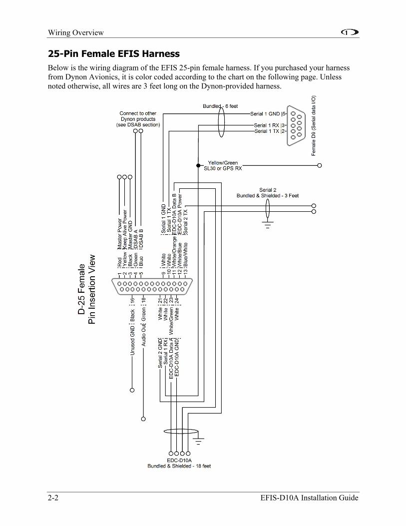
25-Pin Female EFIS Harness Below is the wiring diagram of the EFIS 25-pin female harness. If you purchased your harness from Dynon Avionics, it is color coded according to the chart on the following page. Unless noted otherwise, all wires are 3 feet long on the Dynon-provided harness.
2-2 EFIS-D10A Installation Guide
Wiring Overview
EFIS-D10A Installation Guide 2-3
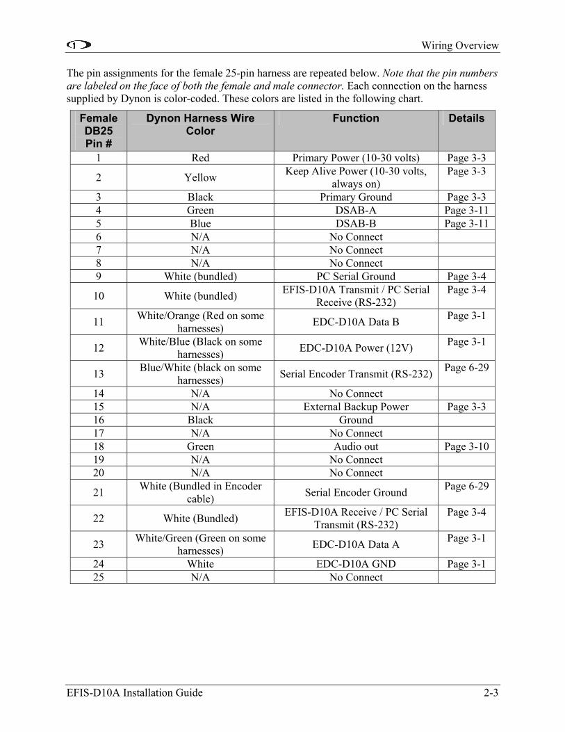
The pin assignments for the female 25-pin harness are repeated below. Note that the pin numbers are labeled on the face of both the female and male connector. Each connection on the harness supplied by Dynon is color-coded. These colors are listed in the following chart.
Female DB25 Pin #
Dynon Harness Wire Color
Function Details
1 Red Primary Power (10-30 volts) Page 3-3
2 Yellow Keep Alive Power (10-30 volts, always on)
Page 3-3
3 Black Primary Ground Page 3-3 4 Green DSAB-A Page 3-11 5 Blue DSAB-B Page 3-11 6 N/A No Connect 7 N/A No Connect 8 N/A No Connect 9 White (bundled) PC Serial Ground Page 3-4
10 White (bundled) EFIS-D10A Transmit / PC Serial Receive (RS-232)
Page 3-4
11 White/Orange (Red on some harnesses) EDC-D10A Data B Page 3-1
12 White/Blue (Black on some harnesses) EDC-D10A Power (12V) Page 3-1
13 Blue/White (black on some harnesses) Serial Encoder Transmit (RS-232) Page 6-29
14 N/A No Connect 15 N/A External Backup Power Page 3-3 16 Black Ground 17 N/A No Connect 18 Green Audio out Page 3-10 19 N/A No Connect 20 N/A No Connect
21 White (Bundled in Encoder cable) Serial Encoder Ground Page 6-29
22 White (Bundled) EFIS-D10A Receive / PC Serial Transmit (RS-232)
Page 3-4
23 White/Green (Green on some harnesses) EDC-D10A Data A Page 3-1
24 White EDC-D10A GND Page 3-1 25 N/A No Connect

Wiring Overview
WIRING SYSTEM OVERVIEW
The following block diagram depicts the basic layout of the EFIS electrical connections and is for reference only. Read the specific instructions for each connection prior to installation. The colors shown refer to the Dynon-supplied EFIS harness.
2-4 EFIS-D10A Installation Guide
EFIS-D10A Installation Guide 3-1
3. INSTRUMENT INSTALLATION
This section provides you with the information needed to physically and electrically install the EFIS-D10A.
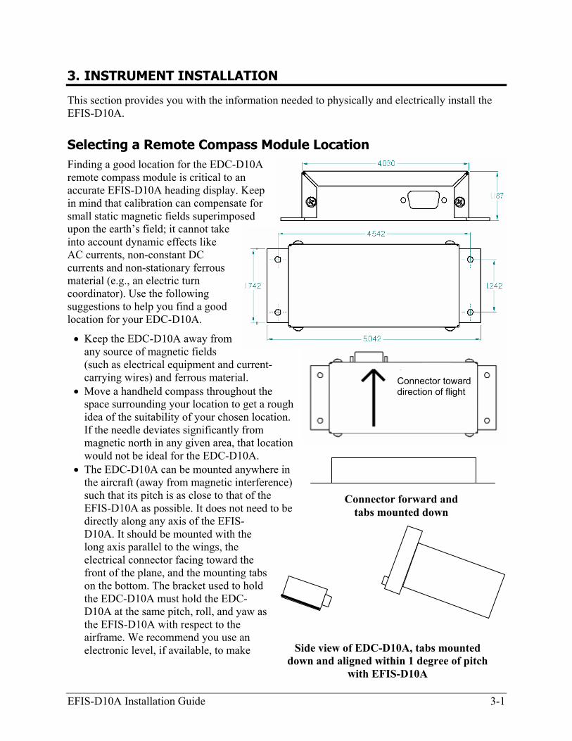
Selecting a Remote Compass Module Location Finding a good location for the EDC-D10A remote compass module is critical to an accurate EFIS-D10A heading display. Keep in mind that calibration can compensate for small static magnetic fields superimposed upon the earth’s field; it cannot take into account dynamic effects like AC currents, non-constant DC currents and non-stationary ferrous material (e.g., an electric turn coordinator). Use the following suggestions to help you find a good location for your EDC-D10A.
• Keep the EDC-D10A away from any source of magnetic fields (such as electrical equipment and current-carrying wires) and ferrous material.
• Move a handheld compass throughout the space surrounding your location to get a roidea of the suitability of your chosen locationIf the needle deviates significantly from magnetic north in any given area, that locatiowould not be ideal for the EDC-D10A.
• The EDC-D10A can be mounted anywhe
ugh .
n
re in
s
the aircraft (away from magnetic interference) such that its pitch is as close to that of the EFIS-D10A as possible. It does not need to be directly along any axis of the EFIS-D10A. It should be mounted with the long axis parallel to the wings, the electrical connector facing toward the front of the plane, and the mounting tabon the bottom. The bracket used to hold the EDC-D10A must hold the EDC-D10A at the same pitch, roll, and yaw asthe EFIS-D10A with respect to the airframe. We recommend you use an electronic level, if available, to make
Connector forward and tabs mounted down
Connector toward direction of flight
Side view of EDC-D10A, tabs mounted down and aligned within 1 degree of pitch
with EFIS-D10A

Instrument Installation
3-2 EFIS-D10A Installation Guide
sure the EDC-D10A is aligned with the EFIS-D10A to better than 1 degree. • All mounting hardware needs to be made from non-ferrous material such as aluminum,
in a
EDC-D10A Communication Cable R UP THE EFIS-D10A WITH THE EDC
32 PC Communication cable, the EDC-D10A communications cable terminates in
.
plastic, or brass. Many stainless steel screws are magnetic. If the item is attracted to a magnet, it should not be used in the installation. The EDC-D10A needs to be mountedlocation as free from magnetic interference as possible. This means keeping the EDC-D10Aaway from any ferrous nuts, bolts, and screws, aircraft tubing, as well as from wires or devices carrying any appreciable current such as strobe light wiring, autopilot servos, orother electronics.
WARNING! DO NOT ATTEMPT TO POWECABLE LEADS EXPOSED (UNSHEATHED) AND NOT INSTALLED IN THE DB9 CONNECTOR. SHORTING THESE CONNECTIONS WILL CAUSE DAMAGE TO THE UNIT. Like the RS-2a standard female DB9 connector. While they look similar, do not plug the EDC cable into a PC or vice versa. The following table outlines the four connections that must be made to ensure proper communication between the EFIS-D10A and the EDC-D10A remote compass moduleThe Dynon-supplied harness colors are listed, as well.
EFIS DB25 pin#
EDC DB9 pin# Function Wire color
11 5 EDC Data B White/Orange (or Red) 12 6 EDC Power White/Blue (or Black) 23 9 EDC Data A White/Green (or Green) 24 1 EDC Ground White
The EDC cable i e harness s lied b ts of 4 condu urrounded by a ins
S harness disconnected from the EFIS-D10A, carefully cut or pull the
10A mounting location chosen according to the instructions
he female pins in the correct holes on the included DB9 connector, according to the
completed. Power on the EFIS-D10A with
red, you
n th upp y Dynon consis ctors, smetal shield and white insulation. These 4 wires are terminated with crimped female D-sub pwrapped in plastic tubing. If you are building your own cable, we recommend that you use shielded cable as well.
• With the 25-pin EFItubing off the 4 D-sub pins.
• Route the cable to the EDC-Dabove.
• Install tchart above. Note that Dynon has shipped harnesses with different colors for the EDC cable; determine your connections using the two sets of colors in the table above.
• Install the back shell around the DB9 connector.
Correct wiring installation can be easily verified oncethe EDC-D10A connected to it. Observe the displayed heading and then hold one of the earpieces of a headset near the front of the EFIS-D10A. If the EDC-D10A is correctly wishould see no change in the displayed heading when the headset earpiece and its magnetic

Instrument Installation
EFIS-D10A Installation Guide 3-3
speaker is near the EFIS-D10A. If you see a substantial change in heading, there is a communication problem between the EFIS-D10A and the EDC-D10A.
The metal shield around the EDC communication cable is connected to the short black/white wire emanating from the DB25. Connect this wire to ground close to the EFIS-D10A, ideally the panel.
Power Inputs The EFIS-D10A has three separate power inputs, located on the DB25 EFIS connector. Of the three, only Primary Power is required to operate the instrument. The other two inputs provide redundancy. Below is a table that explains the three inputs and their purposes. All three of these inputs share a common ground signal, wired to pin 3 on the EFIS connector.
EFIS DB25 pin#
Function EFIS DB25 wire color
Description
1 Primary Power
Red Provides primary power to the instrument. The EFIS-D10A will switch on upon application of power. Connect to a switched power source. Will not be adversely affected by engine cranking.
2 Keep Alive Power
Yellow A very low current power input which is only used if both Master and External Backup Power are not applied. Keep Alive draws just enough current to keep the clock running and keep the optional battery charged. It draws less than 1 milliamp of current when not charging the internal battery. When charging a completely dead internal battery, the Keep Alive line can draw an average of 0.6 amps at 12 volts for 18 hours. If you have the internal battery and do not wish the EFIS-D10A to draw current from your plane’s battery, you do not need to connect Keep Alive. The internal battery will maintain charge without Keep Alive connected as long as the master switch power is turned on for at least 1 hour per month.
3 Primary Ground
Black Connect to ground. Must carry as much as 2 amps.
15 External Backup Power
(Not wired in Dynon
harness)
Will operate the EFIS-D10A only if Primary Power is not present. The transition from Primary Power to External Backup Power will bring up a warning, requiring you to press ACK within 30 seconds to keep the unit operating. This warning will also display when transitioning from either Master or External Backup to Internal Battery power.
Instrument Installation
Serial Communication Cable The EFIS-D10A has one RS-232 serial port for PC communication. This serial port is used for updating the EFIS-D10A’s firmware and checklists and for logging all EFIS-related data.
If you do not have a serial port on your PC, you may use a USB-to-Serial adapter to connect the EFIS-D10A to your PC’s USB port. You may purchase an adapter from us, Radio Shack, or many computer stores. Ensure that the adapter driver CD is inserted in your PC before plugging the adapter into the USB port for the first time. Also, do not have your EFIS-D10A plugged into the USB-to-Serial while installing the driver.
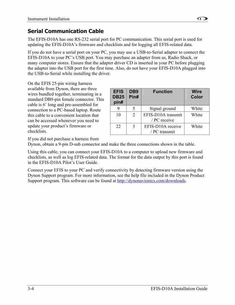
On the EFIS 25-pin wiring harness available from Dynon, there are three wires bundled together, terminating in a standard DB9-pin female connector. This cable is 6’ long and pre-assembled for connection to a PC-based laptop. Route this cable to a convenient location that can be accessed whenever you need to update your product’s firmware or checklists.
EFIS DB25 pin#
DB9 Pin#
Function Wire Color
9 5 Signal ground White 10 2 EFIS-D10A transmit
/ PC receive White
22 3 EFIS-D10A receive / PC transmit
White
If you did not purchase a harness from Dynon, obtain a 9-pin D-sub connector and make the three connections shown in the table.
Using this cable, you can connect your EFIS-D10A to a computer to upload new firmware and checklists, as well as log EFIS-related data. The format for the data output by this port is found in the EFIS-D10A Pilot’s User Guide.
Connect your EFIS to your PC and verify connectivity by detecting firmware version using the Dynon Support program. For more information, see the help file included in the Dynon Product Support program. This software can be found at http://dynonavionics.com/downloads.
3-4 EFIS-D10A Installation Guide

Instrument Installation
SL30 and/or GPS connection Depending on the number and types of Dynon units you own, you have several options for connecting a GPS unit and/or Garmin/Apollo SL30 to your Dynon system. The GPS can be used as a data source for the EFIS, HSI, and Fuel pages. The SL30 can be used as a VOR, localizer, or ILS (localizer + glideslope) source for the HSI. If you wish to connect a GPS and/or SL30 to your Dynon system, read the section below which corresponds to your set of Dynon products.
EFIS-D10A Installation Guide 3-5
If you are installing an HS34, you must connect all GPS and NAV devices to it. The EFIS-D10A does not support directly connected GPS and NAV devices when an HS34 is installed in the system. Refer to the HS34 Installation and Configuration section on page 6-10 for device connection details.
To use the GPS-related features on your EFIS and/or EMS, your GPS must output either “aviation format” or the following NMEA sentences in its serial stream: $GPRMC, $GPRMB, $GPGGA, and one of $GPBOD or $GPAPB. If you own a Garmin 430 or 530, in the UNITS/MAGVAR option, set the MAGVAR to AUTO. The EFIS-D10A auto-detects most GPSs, but may require a manual setting for some. This is true for communication with at least the Garmin 480, GX50, and GX60. From the EFIS menu, enter SETUP >HSI >EFIS_SERIAL; from the EMS menu enter SETUP >GLOBAL >EMS SERIAL. In that menu select the INPUT to be AVIATION and the BAUD RATE to be 9600.
GPSs known to work Garmin 195, 295
Garmin 96, 96c, 196, 296, 396, 496
Garmin 400, 500, 420, 520, 430, 530 (including WAAS) Garmin GX50/GX60 (set to
Aviation format output) Lowrance handhelds
AvMap EKP-IV Garmin 150XL
Bendix/King Skymap (set to Aviation format output)
Other GPSs are untested, but may work.
GPSs with limited functionality Apollo/GNS
480, 580 Possibly works with latest Dynon product firmware,
but untested. Requires manual configuration. See
note at left. AnywhereMap Does not output all needed
sentences. Time output is wrong.
The following connection schemes assume that the external devices share a common ground with the Dynon product(s). If your GPS is battery powered, and not normally connected to aircraft ground, you must connect the ground pin on its serial output to a ground common to the EFIS-D10A.
When a Dynon product is connected to a GPS, it will synchronize its Zulu clock to the time reported by the GPS. However, some GPSs, such as the Garmin 430 and 530, do not report time in their serial output stream. Dynon products have no way to synchronize to these GPSs’ clocks.
Read the section below that corresponds to your configuration of Dynon products. All EFIS-based product configurations direct you to connect your external device to PC serial receive (pin 22) on your Dynon EFIS product. You may make this connection at any point between pin 22 on the EFIS DB25 and pin 3 on the connected DB9 EFIS/PC connector. If you purchased your harness from Dynon Avionics, it may have a yellow/green wire provided for this purpose.

Instrument Installation
3-6 EFIS-D10A Installation Guide
IF YOU OWN ONLY AN EFIS-D10A OR EFIS-D100
Connect the GPS or SL30 transmit line into pin 22 on the DB25 connector. This is the same Serial Rx line that is used for firmware updates. You will need a way to disconnect this when you plug your EFIS into a PC for firmware updates and checklists.
If you have both a GPS unit and an SL30, you will need to wire the two transmit lines to a 3-way switch; connect the output of the switch into pin 22 on the EFIS harness. You will use this switch to toggle between GPS, SL30 and a disconnected state. The HSI auto-detects the switched instrument and will change modes automatically.
IF YOU OWN ONLY AN EMS-D10 OR EMS-D120
We recommend that you only connect a GPS to an EMS-only system; without the magnetic heading from an EFIS, the HSI page will not be functional. Connect the GPS transmit line to pin 19 on the EMS DB37 connector. This connection will give you fuel endurance information (range, MPG, etc) on the fuel page and GPS information only (track, ground-speed, course, etc) on the HSI page. There is no need to break this connection when doing PC updates.
IF YOU OWN AN EMS AND AN EFIS (NOT FLIGHTDEK-D180)
First, ensure that your EMS and EFIS are connected as described in Dynon Smart Avionics Bus (DSAB) Wiring on page 3-11.
If you only have either the GPS or SL30 (but not both), connect the GPS or SL30 transmit line to pin 19 on the EMS DB37 connector. This is labeled “Aux Serial Receive.” With either a GPS or an SL30 connected, you are able to display an HSI on either product; with a GPS connected, you are able to display EMS fuel economy displays.
If you have a GPS and an SL30, connect the GPS to pin 19 on the EMS DB37 connector. Connect the SL30 to pin 22 on the EFIS DB25 connector. This will allow you to flip between GPS and SL30 inputs. However, this option allows you to display a GPS HSI only on the EMS. You can use either the SL30 or GPS as the NAV source on the EFIS product. You will need to disconnect the SL30 from the EFIS when doing software updates.
Alternately, you can connect both the SL30 and the GPS through a switch into the EMS. This will allow you to see both the SL30 and GPS on both the EFIS and EMS, but you will only be able to see one at a time, and you will not be able to see EMS economy data when in SL30 mode.
IF YOU OWN ONLY A FLIGHTDEK-D180
Connect the SL30 unit to pin 22 on the EFIS DB25 connector, and the GPS to pin 19 on the EMS DB37 connector. You can display either source on the HSI using the softkeys. You will need to disconnect the SL30 from the EFIS when doing software updates.
IF YOU OWN A FLIGHTDEK-D180 AND AN EFIS
Connect the SL30 unit to pin 22 on the FlightDEK’s EFIS connector (vertical DB25) and the GPS to pin 19 on the EMS DB37 connector. You can display either source on the HSI, and you can display either on the standalone EFIS as well (provided you have connected the DSAB A &

Instrument Installation
EFIS-D10A Installation Guide 3-7
B lines from the FlightDEK-D180 to the standalone EFIS product). You will need to disconnect the SL30 from the FlightDEK-D180 when doing software updates.
Instrument Installation
3-8 EFIS-D10A Installation Guide
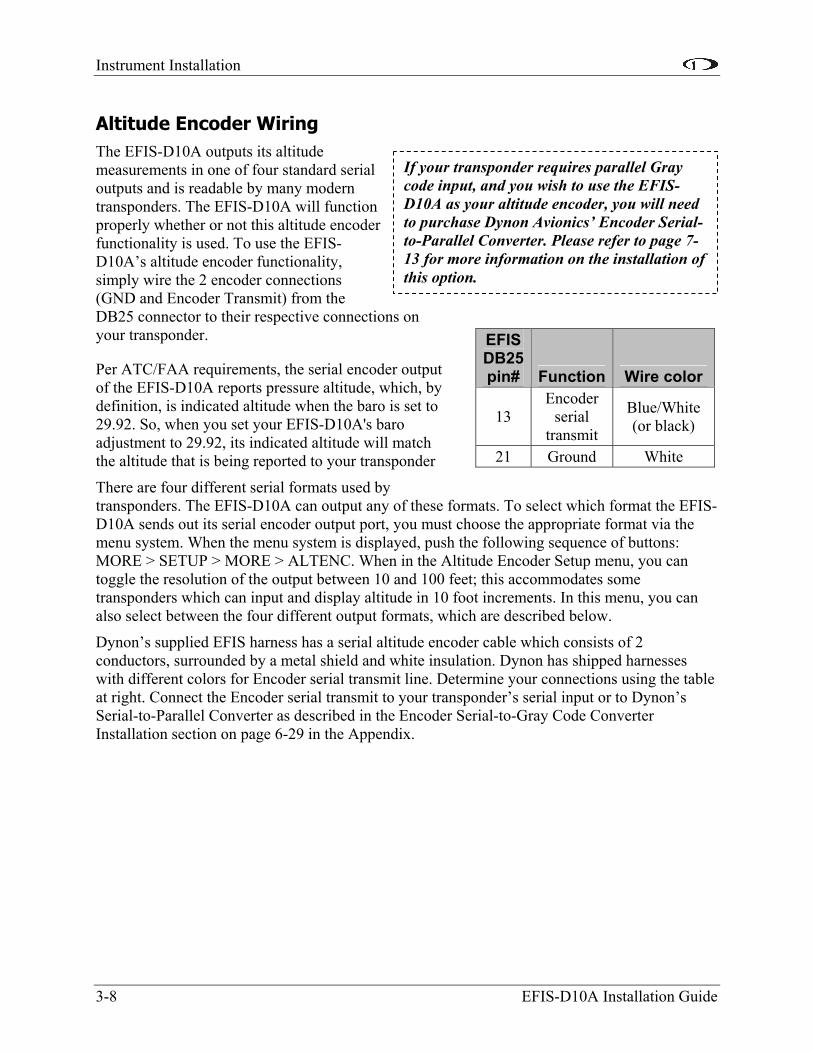
If your transponder requires parallel Gray code input, and you wish to use the EFIS-D10A as your altitude encoder, you will need to purchase Dynon Avionics’ Encoder Serial-to-Parallel Converter. Please refer to page 7-13 for more information on the installation of this option.
Altitude Encoder Wiring The EFIS-D10A outputs its altitude measurements in one of four standard serial outputs and is readable by many modern transponders. The EFIS-D10A will function properly whether or not this altitude encoder functionality is used. To use the EFIS-D10A’s altitude encoder functionality, simply wire the 2 encoder connections (GND and Encoder Transmit) from the DB25 connector to their respective connections on your transponder.
Per ATC/FAA requirements, the serial encoder output of the EFIS-D10A reports pressure altitude, which, by definition, is indicated altitude when the baro is set to 29.92. So, when you set your EFIS-D10A's baro adjustment to 29.92, its indicated altitude will match the altitude that is being reported to your transponder
There are four different serial formats used by transponders. The EFIS-D10A can output any of these formats. To select which format the EFIS-D10A sends out its serial encoder output port, you must choose the appropriate format via the menu system. When the menu system is displayed, push the following sequence of buttons: MORE > SETUP > MORE > ALTENC. When in the Altitude Encoder Setup menu, you can toggle the resolution of the output between 10 and 100 feet; this accommodates some transponders which can input and display altitude in 10 foot increments. In this menu, you can also select between the four different output formats, which are described below.
Dynon’s supplied EFIS harness has a serial altitude encoder cable which consists of 2 conductors, surrounded by a metal shield and white insulation. Dynon has shipped harnesses with different colors for Encoder serial transmit line. Determine your connections using the table at right. Connect the Encoder serial transmit to your transponder’s serial input or to Dynon’s Serial-to-Parallel Converter as described in the Encoder Serial-to-Gray Code Converter Installation section on page 6-29 in the Appendix.
EFIS DB25 pin# Function Wire color
13 Encoder
serial transmit
Blue/White (or black)
21 Ground White

Instrument Installation
EFIS-D10A Installation Guide 3-9
SERIAL ALTITUDE FORMATS
There are four formats used by serial transponders. Choose the correct format for your transponder in the ALTENC menu, using the FRMAT button.
Format 1
Used By Garmin AT (formerly UPS Aviation Technologies), Dynon Encoder Serial-to-Parallel Converter
Baud rate 1200 Format #AL, space, +/-sign, five altitude bytes, T+25, checksum,
carriage return Example message #AL +05200T+25D7[CR]
Format 2
Used By Magellan Baud rate 1200
Format $MGL, +/- sign, five altitude digits, T+25, checksum, carriage return
Example message $MGL+05200T+25E3[CR]
Format 3
Used By Northstar, Garmin Baud rate 2400
Format ALT, space, five altitude bytes, carriage return Example message ALT 05200[CR]
Format 4
Used By Trimble, Garmin GTX327 (set on Icarus input), Garmin GTX330 (set on Icarus input), Icarus
Baud rate 9600 Format ALT, space, five altitude bytes, carriage return
Example message ALT 05200[CR]
Instrument Installation
3-10 EFIS-D10A Installation Guide
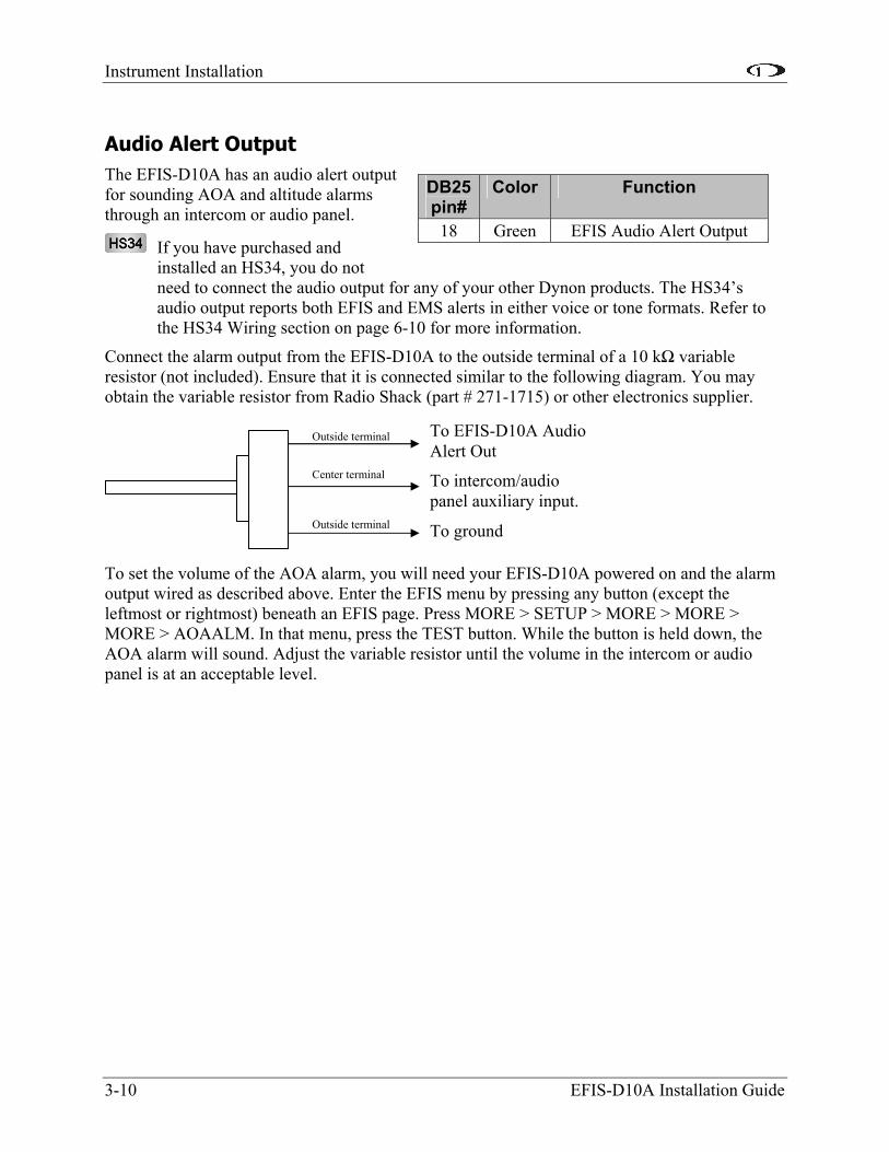
Audio Alert Output The EFIS-D10A has an audio alert output for sounding AOA and altitude alarms through an intercom or audio panel.
If you have purchased and installed an HS34, you do not need to connect the audio output for any of your other Dynon products. The HS34’s audio output reports both EFIS and EMS alerts in either voice or tone formats. Refer to the HS34 Wiring section on page 6-10 for more information.
Connect the alarm output from the EFIS-D10A to the outside terminal of a 10 kΩ variable resistor (not included). Ensure that it is connected similar to the following diagram. You may obtain the variable resistor from Radio Shack (part # 271-1715) or other electronics supplier.
To set the volume of the AOA alarm, you will need your EFIS-D10A powered on and the alarm output wired as described above. Enter the EFIS menu by pressing any button (except the leftmost or rightmost) beneath an EFIS page. Press MORE > SETUP > MORE > MORE > MORE > AOAALM. In that menu, press the TEST button. While the button is held down, the AOA alarm will sound. Adjust the variable resistor until the volume in the intercom or audio panel is at an acceptable level.
DB25 pin#
Color Function
18 Green EFIS Audio Alert Output
To EFIS-D10A Audio Alert Out
To intercom/audio panel auxiliary input.
To ground
Outside terminal
Center terminal
Outside terminal
Instrument Installation
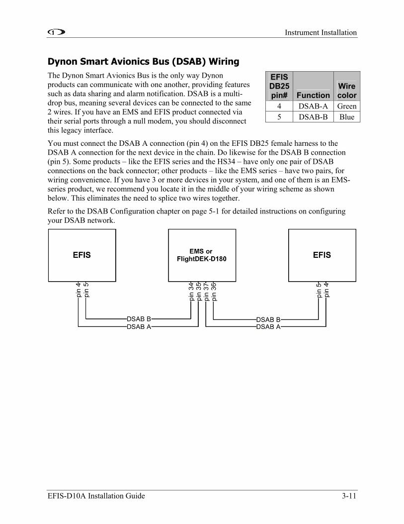
Dynon Smart Avionics Bus (DSAB) Wiring The Dynon Smart Avionics Bus is the only way Dynon products can communicate with one another, providing features such as data sharing and alarm notification. DSAB is a multi-drop bus, meaning several devices can be connected to the same 2 wires. If you have an EMS and EFIS product connected via their serial ports through a null modem, you should disconnect this legacy interface.
EFIS DB25 pin# Function
Wire color
4 DSAB-A Green5 DSAB-B Blue
You must connect the DSAB A connection (pin 4) on the EFIS DB25 female harness to the DSAB A connection for the next device in the chain. Do likewise for the DSAB B connection (pin 5). Some products – like the EFIS series and the HS34 – have only one pair of DSAB connections on the back connector; other products – like the EMS series – have two pairs, for wiring convenience. If you have 3 or more devices in your system, and one of them is an EMS-series product, we recommend you locate it in the middle of your wiring scheme as shown below. This eliminates the need to splice two wires together.
Refer to the DSAB Configuration chapter on page 5-1 for detailed instructions on configuring your DSAB network.
EFIS-D10A Installation Guide 3-11

Instrument Installation
3-12 EFIS-D10A Installation Guide
Panel Location and Mounting The diagram at right shows the outside dimensions of the front bezel of the EFIS-D10A. Note that the instrument is about seven inches deep and the supplied harness extends three inches more. Use the dimensions (in inches) found on the diagram to plan for the space required by the instrument. Take the following considerations into account when selecting a mounting location for the EFIS-D10A.
Avoid placing the instrument near heater vents or any source of extremely hot or cold air. Keep in mind that the air surrounding the EFIS-D10A during operation may be no warmer than 50 °C to ensure accurate operation. Plan a panel location that allows convenient viewing of the instrument with no obstruction. When flying straight and level, the panel angle from vertical may not be greater than +/- 30 degrees. The unit must be aligned as close as possible with the roll and yaw axes of the airplane. The firmware supports an adjustment for panel tilt, but not for mounting errors in yaw or roll. Correct attitude performance depends on mounting the EFIS-D10A square with the direction of flight.
You have two options for mounting the EFIS-D10A into your panel: standard or flush. You may use the optional flush-mount bracket, allowing the face of the EFIS-D10A to be flush with your panel. If you opted to receive the flush mount bracket, please skip to Option 2 below. If you opted not to receive this bracket and wish to perform the standard install, follow the options in Option 1 below.
OPTION 1: NO MOUNTING BRACKET
Using this option, you will be mounting the EFIS-D10A directly into your panel. The front bezel of the unit will extend beyond the plane of your panel by 0.8”.

Instrument Installation
Installation of the EFIS-D10A main unit should only be completed once all other physical and electrical installations have been performed. This will insure that last-minute adjustments will not have to be made with the EFIS-D10A mounted in the panel.
The diagram above shows the dimensions expected for the proper installation of the EFIS-D10A into your panel using no mounting bracket. All units are in inches. Push the EFIS-D10A through the main panel hole. The four studs on the back of the EFIS-D10A will fit into the four mounting holes having dimensions listed in the diagram. Place one of the four supplied washers on each stud before pushing the EFIS-D10A into place in the panel, putting the washers in between the EFIS-D10A and the panel. Place one of the 4 supplied mounting nuts on the end of each of the 4 studs protruding from the back of the panel. Secure the nuts tightly against the panel to complete the installation.
OPTION 2: FLUSH-MOUNT BRACKET
Make a rectangular cutout in your panel, ensuring that it allows the front panel of the EFIS-D10A to fit. The cutout required should have the dimensions 4.09” wide by 3.39” tall with corner radii of 0.125”. You also need to drill four 0.164” holes in your panel at the four locations shown on the diagram below (two above and two below the rectangular cutout). Install #6 plate nuts on the back side of the bracket. Place one of the supplied washers onto each of the four mounting studs on the EFIS-D10A and then slide the flush mount bracket over the EFIS-D10A. The bracket should wrap around the bezel of the EFIS-D10A. Place one of the 4 supplied nuts on each of the 4 studs and tighten the nuts. The EFIS-D10A/bracket can now be installed from behind your panel using the #6 screws through the previously drilled holes.
EFIS-D10A Installation Guide 3-13

Instrument Installation
Connecting Static & Pitot Lines
3-14 EFIS-D10A Installation Guide
The AOA, pitot, and static ports on the back of the EFIS-D10A are equipped with 1/8” NPT Female fittings. To attach your pitot and static lines to the back of the EFIS-D10A, you must use standard 1/8” NPT Male fittings at the end of each of the lines.
The FlightDEK-D180’s attitude calculation requires airspeed data obtained via the pitot and static lines. To ensure proper operation, you MUST connect these ports to the pitot and static systems in your plane.To install, simply connect your static and pitot
sources to the EFIS-D10A, T’ing off of existing lines if performing a retrofit. View the following back view diagram the placement of your pressure lines.
Use two wrenches to both hold the brass fitting on the EFIS-D10A and secure the mating pressure line fittings to the corresponding locations on the back of the EFIS-D10A. Do not over-tighten or allow the brass fittings to rotate.
If you purchased Dynon’s AOA pitot tube, note that it has pitot and AOA ports on it, but not static. You will need to provide your own source of static pressure for the EFIS-D10A and any other instrument in your panel which requires it.
AOA
Pitot
StatiStatic
4. EFIS CALIBRATION AND CONFIGURATION
During manufacture, your EFIS-D10A underwent a comprehensive calibration, verification, and burn-in routine that minimizes setup time and ensures that your EFIS meets Dynon's stringent performance specifications. To account for your individual preferences and your aircraft's particular setup, there are a few simple calibration and configuration steps that you must complete before using your EFIS-D10A. This section takes you through these steps to make sure that you have properly installed and configured your EFIS-D10A.
CAUTION: It is your responsibility to fly your plane safely while performing any configuration or calibration in flight. The best scenario would include a second person to perform any necessary steps on the unit.
Ensuring Proper Installation Turn your unit on by energizing the aircraft power to which it is connected. Ensure that the screen is bright and readable and that all instrument displays appear. If a desired display item is not present, refer to the User’s Guide to use the CLUTTR feature to display the missing item.
Setting Zero Pitch (In flight) NOTE: For the purposes of this setting, level is defined as the attitude at which the airplane's longitudinal axis is parallel to the ground. For most aircraft, the attitude the airplane assumes at normal cruise speeds will be acceptable. Additionally, this feature should not be used to “zero out” pitch when the aircraft is at an attitude other than level. Do not think of this adjustment as you would the parallax adjustment on a normal attitude indicator. Instead, think of it as a calibration step which is not changed often.
With your aircraft flying straight and level, enter the EFIS > SETUP > PITCH menu. Press INC or DEC until the horizon line intersects the center of the crosshairs. It is important that this be done while the aircraft is level to ensure proper pitch and roll display throughout all maneuvers.
Compass Heading Calibration This section guides you through the calibration and configuration of your magnetic heading indication. Prior to calibrating your EFIS-D10A’s internal sensors or remote EDC-D10A, you must configure the local magnetic inclination and magnetic intensity as described in the sections below.
In a DSAB network, the Bus Master’s heading is used as the only heading source for all connected instruments. However, in the event of a DSAB failure, EFIS instruments revert to their local heading source. In a system already using a shared heading, you may still configure and calibrate the local heading source. As soon as you bring up any of the magnetic calibration menus (MAGINC, MAGCAL, MAGADJ, MAGINT), the heading and DG displays switch to display the locally-derived heading indication. The display stays on that source until exiting the magnetic configuration menu. If you do not have an EDC-D10A connected, REMOTE COMPASS NOT DETECTED is displayed when in any of these menus.
EFIS-D10A Installation Guide 4-1
Error! Reference source not found.
SETTING MAGNETIC INCLINATION ANGLE AND INTENSITY (REQUIRED)
In order to calibrate your EFIS-D10A heading, you must input your location’s current magnetic inclination angle and intensity. Before doing this, you must obtain these two values for the geographic location where you will be performing the calibration. Note that this procedure only needs to be done once, prior to magnetic calibration; moving the aircraft to another location does not require repeating this procedure.
Obtaining Magnetic Inclination and Intensity
1. Connect to the internet and point your browser to http://www.dynonavionics.com/docs/maginfo.html.
2. This page lists instructions for finding your local magnetic inclination and intensity and will point you to a site where you can input your ZIP code (in the US) or your latitude and longitude. If you enter a ZIP code, you must click on “Get Location” to get the correct latitude and longitude. Ensure that you enter the location where you will actually be performing the calibration.
3. After clicking “Get Location”, confirm that latitude and longitude fields are no longer zeroed out. If they are, your zip code may not be in the NOAA database. If this happens, try another zip code nearby.
4. Once that data is entered, you must select “Compute Magnetic Field Values” at the bottom of the page.
5. Note the angle next to the heading “Inclination =.” This is your local magnetic inclination angle. In most of North America and Europe, this value should be between 50 and 80 degrees. When entering the inclination into the EFIS-D10A, round to the nearest 0.5º.
6. Note the 5-digit number next to the heading “Total Intensity =.” This is your local magnetic intensity. When entering the intensity into the EFIS-D10A, round to the nearest whole number.
Entering inclination and intensity into the EFIS-D10A
1. Enter the inclination setup menu by pressing any button beneath an EFIS page (except the far left or far right hotkeys), then MORE > SETUP > MORE > MORE > MAGINC
2. Press INC or DEC to increment or decrement the displayed inclination angle. Press and hold to change values more rapidly.
3. When the display shows the magnetic inclination angle for your location, press BACK to leave the menu.
4. Enter the magnetic intensity setup menu by pressing any button beneath an EFIS page (except the far left or far right hotkeys), then MORE > SETUP > MORE > MORE > MAGINT
5. Press SEL to change the digit being incremented or decremented. Press INC or DEC to increment or decrement the selected digit. Press and hold to change values more rapidly.
6. When the display shows the magnetic intensity for your location, press BACK to leave the menu.
4-2 EFIS-D10A Installation Guide

Error! Reference source not found.
EFIS-D10A Installation Guide 4-3
It is crucial that compass heading calibration be done after the unit is completely integrated into your panel. If the unit is calibrated away from the panel and then inserted at a later time, it will be improperly biased by the unique magnetic field characteristics of your plane.
EFIS-D10A (INTERNAL) HEADING CALIBRATION (ON GROUND AND IN FLIGHT)
NOTE: if you own the EDC-D10A Remote Compass Module, you do not need to perform this set of steps. Skip to the next section for calibration of the remote compass.
Because our goal is to give the EFIS-D10A a compass that is accurate in all attitudes, our user magnetic calibration process is more comprehensive than that for many other products. The magnetic field vector in North America is predominantly vertical; this requires that any complete calibration maneuver bank the airplane significantly in order to accurately map out the unique magnetic signature of your plane in this three-dimensional field. Therefore, a large quantity of data needs to be recorded in a variety of attitudes. Simpler calibration processes do not perform these steps and suffer by being accurate only at level attitudes. When properly completed, a magnetic calibration of this complexity will produce a compass that is accurate during banked maneuvers. Note that the EDC-D10A remote compass calibration process is not as complex because it is assumed that you have mounted it in a more magnetically clean environment. Three dimensional calibration has already been done on the EDC-D10A at the factory.
Before proceeding with the calibration, ensure that you have determined and entered the magnetic inclination (dip angle) as described above.
Performing the calibration
Perform the first portion of the heading calibration on the ground in an area where you can accurately determine magnetic North such as on a compass rose. You must also have enough room to perform a 540 turn on the ground as described below. Turn the EFIS-D10A on and let it warm up for 10-15 minutes before proceeding. Turn all instruments on that you would normally be operating during a flight, including the engine.
During magnetic calibration, do not turn the power off on the EFIS-D10A. This will cause any recorded compass calibration data to be lost; the calibration will need to be restarted.
1. Enter the EFIS calibration menu by pressing any button beneath an EFIS page (except the far left or far right hotkeys), then MORE > SETUP > MORE > MORE > MAGCAL. You should see a menu that reads GNDNRT, AIRRGT, and AIRLFT. If it reads NORTH, EAST, SOUTH, and WEST, you have the EDC-D10A installed and should proceed with the EDC-D10A heading calibration as described on the following page.
2. With the plane in the normal flight state (engine running, all instruments and avionics on), align the plane to point as close as possible to magnetic North. Press the GNDNRT button (the button’s text will toggle to DONE – do not press this until the maneuver is complete) and hold the plane still for 10 seconds. After the 10 seconds of holding still, maneuver the plane smoothly to the right through 540 degrees of heading change at a rate of 20 to 30 seconds per 90 degrees of change; the whole maneuver should take between 2 and 3 minutes. At the end of the maneuver, the airplane will be pointing magnetic South. At this point, press DONE. If at any time, you make a mistake, press DONE, align the

Error! Reference source not found.
aircraft to point to magnetic North and repeat the process, starting with pushing the GNDNRT button.
3. Now proceed to take off for the in-flight part of the calibration. After reaching a safe altitude, head the plane as close as possible to magnetic North. Press the AIRRGT button (again, the button’s text will toggle to DONE – wait until completing the maneuver before pressing this), and continue holding a steady North heading for 10 seconds. Then make a 30 degree banked turn to the right for 540 degrees. The maneuver ends with the aircraft pointing South. Fly the maneuver as smooth as possible since this will give you better results. At the end of the maneuver, while still pointing South, press the DONE button.
4. Maneuver the aircraft to point to magnetic North again. Press the AIRLFT button (toggling it to DONE – again, refrain from pressing until the maneuver is complete). Continue holding a steady heading (North) for 10 seconds, and then make a 30 degree banked turn to the left for 540 degrees. The maneuver ends with the aircraft pointing South. Fly the maneuver as smooth as possible since this will give you better results. At the end of the maneuver, while still pointing South, press the DONE button.
5. At any point in the calibration, you may redo a maneuver by pressing the appropriate button and repeating that step. The order in which you do the 3 maneuvers is not critical as long as all three maneuvers are performed completely without cycling the power to the EFIS-D10A.
6. When you are satisfied with the three maneuvers, press END. This will cause the EFIS-D10A to calculate the values needed for calibration. This process can take as long as 10 minutes, during which your EFIS-D10A will appear “frozen.” A message will be displayed onscreen: CALCULATING MAGNETIC CALIBRATION VALUES.
7. Wait for the message CALIBRATION COMPLETE before attempting to use the EFIS-D10A or remove power. Press BACK to leave the menu.
At this point the calibration is complete. We suggest you evaluate the performance of the EFIS-D10A heading feature, preferably on a compass rose, and decide if the performance is acceptable to you. If the resultant compass accuracy is not acceptable, you can either repeat the calibration process attempting to fly the maneuvers more smoothly, or purchase, install, and calibrate the Dynon Avionics EDC-D10A Remote Compass.
You will need to repeat this process anytime you move the EFIS-D10A to a new location in your plane or change the magnetic or electrical characteristics of the nearby environment (i.e. adding or removing other electrical instruments). Changing geographic location should have no effect on your heading readings after a user calibration.
Troubleshooting
During the calibration process you may receive one of the following errors. Next to each one is the corrective action required.
• WARNING: MAGNETIC INCLINATION NOT SET. You have not entered the magnetic inclination into the EFIS-D10A yet. Please see the “Entering the Inclination Angle” section above.
4-4 EFIS-D10A Installation Guide

Error! Reference source not found.
• ERR: NOT ENOUGH DATA FOR XXXXXX TURN. One of the 3 maneuvers did not take enough time for the EFIS-D10A to collect enough data. Please perform just the listed maneuver again, ensuring that you take at least 2 minutes to perform the turn.
• ERR: HOLD N LONGER BEFORE XXXXXX TURN. The EFIS-D10A did not see enough data for the 10 second north-bound section of the turn. Repeat the listed maneuver, ensuring that you spend 10 seconds pointed north before beginning the turn.
• ERR: XXXXXX 540 DEG TURN NOT COMPLETED. The EFIS-D10A did not see a complete 540 degree turn. Repeat the listed maneuver, ensuring that you turn through the entire 540 degrees, ending up pointed south.
EDC-D10A HEADING CALIBRATION (ON GROUND ONLY)
The procedure for in-plane calibration of the EDC-D10A involves pointing the aircraft in four directions and taking data at each direction using the EFIS-D10A. The EFIS-D10A will then perform some calculations to ensure an accurate calibration.
During magnetic calibration, do not turn the power off on the EFIS-D10A. This will cause any recorded compass calibration data to be lost; the calibration will need to be restarted.
To perform the calibration, you will need the following:
1. EFIS-D10A and EDC-D10A installed in aircraft.
2. Magnetic inclination angle entered into the EFIS-D10A. Refer to the Magnetic Inclination section above for information about determining the magnetic inclination angle and loading it into the EFIS-D10A.
3. An accurate method of aligning the airplane with magnetic North, East, South, and West. An airport compass rose works well.
Once you have the installation completed, have verified that your EDC-D10A communicates with the EFIS-D10A (via the headphone test described in the installation section), and have located a suitable place to perform the calibration, perform the following steps:
1. Turn on the EFIS-D10A and allow it to warm up for at least 15 minutes before performing the calibration.
2. Align the airplane pointing magnetic North as closely as possible.
3. On the EFIS-D10A, enter the menu system by pressing any button beneath an EFIS page (except the far left or far right hotkeys) and press MORE > SETUP > MORE > MORE > MAGCAL. You should see a menu that reads NORTH, EAST, SOUTH, and WEST. If you do not, then the EDC-D10A is not properly communicating with your EFIS-D10A.
4. Press the NORTH button; you will see the message, COLLECTING DATA FOR NORTH along with a 15 second timer. Let the time run out before proceeding.
5. Align the airplane pointing magnetic East as closely as possible.
6. Press the EAST button; you will see the message, COLLECTING DATA FOR EAST along with a 15 second timer. Let the time run out before proceeding.
7. Align the airplane pointing magnetic South as closely as possible.
EFIS-D10A Installation Guide 4-5
Error! Reference source not found.
8. Press the SOUTH button; you will see the message, COLLECTING DATA FOR SOUTH along with a 15 second timer. Let the time run out before proceeding.
9. Align the airplane pointing magnetic West as closely as possible.
10. Press the WEST button; you will see the message, COLLECTING DATA FOR WEST along with a 15 second timer. Let the time run out before proceeding.
11. Press the END button. This will cause the EFIS-D10A to pause as it calculates. This pause should last between 1-20 seconds. However, if the collected data is poor, this can take as long as 5 minutes. A message will be displayed onscreen: CALCULATING MAGNETIC CALIBRATION VALUES.
12. Wait for the message CALIBRATION COMPLETE before attempting to use the EFIS-D10A or remove power. Press BACK to leave the menu.
This completes the EDC-D10A calibration process. The process can be repeated as often as desired. The overall accuracy of the compass depends on the installation location (away from any ferrous materials or current carrying wires or devices), the installation alignment (aligned with the EFIS-D10A in pitch, roll, and yaw), and the calibration procedure (accurately aligning the aircraft with North, East, West, and South and having the correct magnetic inclination angle loaded into the EFIS-D10A). If the compass performance is not adequate for your usage, we suggest that you investigate each of these factors and try to optimize your installation for each factor.
If the heading shown onscreen is off by a small, but constant amount, you can change a heading offset in the EFIS-D10A which will correct this. Orient your plane in a known direction, preferably on a compass rose at the airport. Navigate to the Heading Adjustment menu by pressing MORE > SETUP > MORE > MORE > MAGADJ. Increment or decrement the value of the heading offset until the EFIS-D10A heading corresponds to the direction in which your plane is pointed.
4-6 EFIS-D10A Installation Guide

Error! Reference source not found.
EFIS-D10A Installation Guide 4-7
Configure Airspeed Color Thresholds To configure the airspeed bar color thresholds for your unit enter the EFIS > SETUP > IASCLR menu. This displays the Airpseed Color Threshold menu. In this menu, enter the values for five airspeed constants (Vso, Vs1, Vfe, Vno, and Vne), each of which has its own button. Enter these values in units of knots, mph, or km/h depending on what airspeed units you are currently using (you may change the displayed airspeed units via EFIS > SETUP > UNITS > IAS).
Perform the following steps for each airspeed constant:
1. Press SEL to select the digit you wish to increment or decrement.
2. Press DEC- or INC+ to decrement or increment the selected digit.
3. Press BACK to return to the previous menu.
Note that you will not be able to see some of the colors until the aircraft has achieved airspeeds in the range of each threshold.


5. DSAB CONFIGURATION
This section introduces some concepts that are central to understanding and configuring a network of DSAB-capable Dynon products. It then takes you through a series of simple steps to configure your network, enabling data sharing and HS34 functionality. Do not proceed with DSAB configuration until you perform all installation, calibration, and configuration steps for each instrument with a display. Display-less instruments – such as the HS34 – cannot be fully configured until DSAB is active, although their physical and electrical installation should be complete.
Network Concepts A few concepts must be understood before configuring a DSAB-connected system. The most important is that of Dynon products as providers of functions to the network. These various functions are called roles. Some products, such as the HS34, only have one role on the network; other products can provide multiple roles at a time. When a device has been assigned to provide a role to the network, no other device on the network can provide that role at the same time.
The table at right lists all available roles and the products which they can be assigned to. Again, each role can be assigned to no more than one device on the network.
Assignable roles by product EF
IS-D
10A
/ EF
IS-D
100
EMS-
D10
/ EM
S-D
120
Flig
htD
EK-
D18
0
HS3
4
Bus Master X X EFIS X X EMS X X OAT X X X
Compass X X HS34 X
Another important concept is that of the bus master. A DSAB-connected network must have at least one EFIS-based product (EFIS-D10A, EFIS-D100, or FlightDEK-D180), and only an EFIS-based product can be assigned the bus master role. The bus master is the instrument which manages communication on the network. If the bus master is turned off or fails all data sharing ceases, causing units to display internally-derived data only. When you first perform DSAB network configuration on an EFIS-based instrument, that device is automatically assigned the bus master role. Perform DSAB configuration on your primary EFIS-based instrument, as the bus master is also the default provider for both the EFIS and Compass roles.
Example Networks The following two pages present diagrams of example DSAB-connected networks. These examples illustrate and expand upon some of the concepts discussed above. The first diagram depicts a system without an HS34 connected, demonstrating where NAV and GPS devices should be connected. The second diagram depicts a system with an HS34 connected, demonstrating that all NAV and GPS devices must be connected to the HS34. Both diagrams discuss what devices can be assigned various roles and what happens when DSAB fails.
EFIS-D10A Installation Guide 5-1

DSAB Configuration
5-2 EFIS-D10A Installation Guide

DSAB Configuration
EFIS-D10A Installation Guide 5-3
DSAB Configuration
5-4 EFIS-D10A Installation Guide
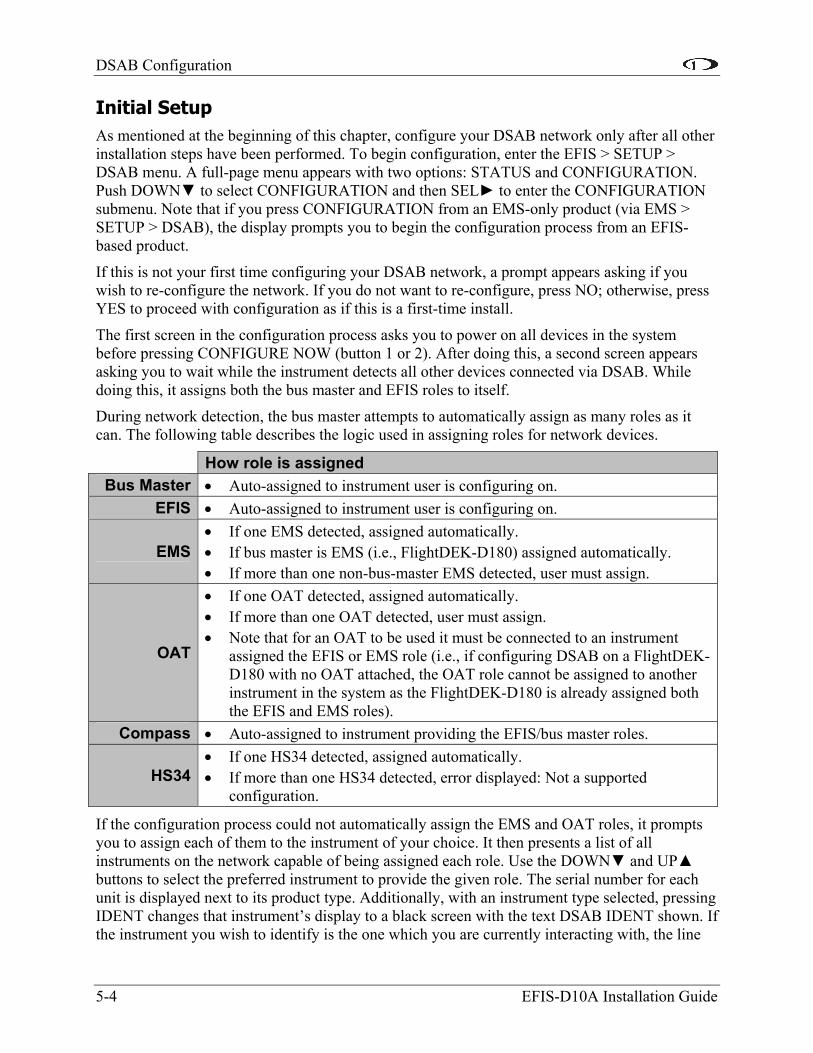
Initial Setup As mentioned at the beginning of this chapter, configure your DSAB network only after all other installation steps have been performed. To begin configuration, enter the EFIS > SETUP > DSAB menu. A full-page menu appears with two options: STATUS and CONFIGURATION. Push DOWN to select CONFIGURATION and then SEL to enter the CONFIGURATION submenu. Note that if you press CONFIGURATION from an EMS-only product (via EMS > SETUP > DSAB), the display prompts you to begin the configuration process from an EFIS-based product.
If this is not your first time configuring your DSAB network, a prompt appears asking if you wish to re-configure the network. If you do not want to re-configure, press NO; otherwise, press YES to proceed with configuration as if this is a first-time install.
The first screen in the configuration process asks you to power on all devices in the system before pressing CONFIGURE NOW (button 1 or 2). After doing this, a second screen appears asking you to wait while the instrument detects all other devices connected via DSAB. While doing this, it assigns both the bus master and EFIS roles to itself.
During network detection, the bus master attempts to automatically assign as many roles as it can. The following table describes the logic used in assigning roles for network devices.
How role is assigned Bus Master • Auto-assigned to instrument user is configuring on.
EFIS • Auto-assigned to instrument user is configuring on.
EMS • If one EMS detected, assigned automatically. • If bus master is EMS (i.e., FlightDEK-D180) assigned automatically. • If more than one non-bus-master EMS detected, user must assign.
OAT
• If one OAT detected, assigned automatically. • If more than one OAT detected, user must assign. • Note that for an OAT to be used it must be connected to an instrument
assigned the EFIS or EMS role (i.e., if configuring DSAB on a FlightDEK-D180 with no OAT attached, the OAT role cannot be assigned to another instrument in the system as the FlightDEK-D180 is already assigned both the EFIS and EMS roles).
Compass • Auto-assigned to instrument providing the EFIS/bus master roles.
HS34 • If one HS34 detected, assigned automatically. • If more than one HS34 detected, error displayed: Not a supported
configuration.
If the configuration process could not automatically assign the EMS and OAT roles, it prompts you to assign each of them to the instrument of your choice. It then presents a list of all instruments on the network capable of being assigned each role. Use the DOWN and UP buttons to select the preferred instrument to provide the given role. The serial number for each unit is displayed next to its product type. Additionally, with an instrument type selected, pressing IDENT changes that instrument’s display to a black screen with the text DSAB IDENT shown. If the instrument you wish to identify is the one which you are currently interacting with, the line
DSAB Configuration
changes to read THIS UNIT. When you have selected the preferred provider for the role, press SELECT to continue in the process. If necessary, repeat with the next manually assigned role.
At this point, a screen is displayed indicating that network configuration is complete. Press FINISH to end the configuration. You may repeat the configuration process as many times as you wish. Whenever you add or remove an instrument from your network, you must redo the DSAB configuration process.
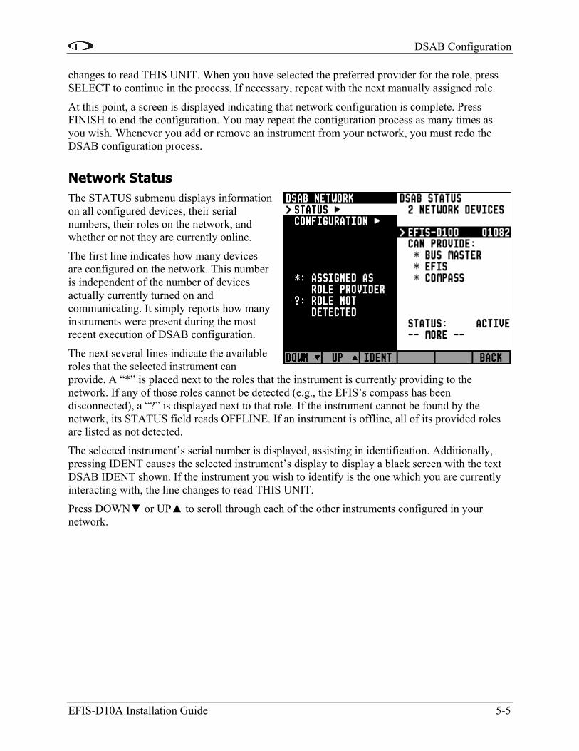
Network Status The STATUS submenu displays information on all configured devices, their serial numbers, their roles on the network, and whether or not they are currently online.
EFIS-D10A Installation Guide 5-5
The first line indicates how many devices are configured on the network. This number is independent of the number of devices actually currently turned on and communicating. It simply reports how many instruments were present during the most recent execution of DSAB configuration.
The next several lines indicate the available roles that the selected instrument can provide. A “*” is placed next to the roles that the instrument is currently providing to the network. If any of those roles cannot be detected (e.g., the EFIS’s compass has been disconnected), a “?” is displayed next to that role. If the instrument cannot be found by the network, its STATUS field reads OFFLINE. If an instrument is offline, all of its provided roles are listed as not detected.
The selected instrument’s serial number is displayed, assisting in identification. Additionally, pressing IDENT causes the selected instrument’s display to display a black screen with the text DSAB IDENT shown. If the instrument you wish to identify is the one which you are currently interacting with, the line changes to read THIS UNIT.
Press DOWN or UP to scroll through each of the other instruments configured in your network.


6. APPENDIX
The appendices contain additional information pertaining to the installation and maintenance of the EFIS-D10A. You will find here a table of weights, specifications, a configuration table, the maintenance manual, the OAT Installation and Operating Guide, the AOA Pitot Installation Guide, and the Blind encoder Serial-to-Parallel Installation Guide.
Appendix A: Instructions for Continued Airworthiness
INTRODUCTION
This section gives the installer or mechanic information pertaining to maintenance of the EFIS-D10A. Additionally, it provides the steps necessary to ensure continued airworthiness for the unit.
CAUTION
With the exception of replacing the internal emergency battery, the EFIS-D10A contains no user-serviceable parts. Refer all servicing to Dynon Avionics.
INSTRUCTIONS FOR CONTINUED AIRWORTHINESS
Other than for regulatory periodic checks and an annual internal battery capacity test (if optional internal emergency battery is installed), maintenance of the EFIS-D10A is “on-condition” only. With the exception of the battery, periodic maintenance of the EFIS-D10A is not required.
ALTIMETER CHECK
The following test can be performed on an as-needed basis. If the altimeter is found to be out of specification, the following single-point adjustment can be performed by navigating the menus to SETUP > ALTADJ. In the Altimeter Adjustment menu, you can change the displayed altitude by up to 500 feet up or down. After making this adjustment, ensure that the altimeter on the EFIS-D10A meets the tolerances allowed between 0 and 30,000 feet. If this adjustment does not bring the altimeter on the EFIS-D10A to within specification at all attitudes, please contact Dynon Avionics to return for service.
INTERNAL BATTERY CHECK
If your EFIS-D10A has a rechargeable internal emergency battery, it is necessary to ensure that the battery capacity is such that it will last at least 2 hours on a full charge. At least once per year, perform the following test.
1. With the EFIS-D10A drawing power from an external source, allow it to charge its internal battery above 16.0 volts. Observe the voltmeter under the INFO selection option in the menu system. The battery may charge to as high as 16.8 volts, but it is only necessary to charge it to 16.0 volts for this test.
2. Remove all sources of external power from the EFIS-D10A, ensuring that it is operating off its internal battery.
EFIS-D10A Installation Guide 6-1

Appendix
6-2 EFIS-D10A Installation Guide
3. Ensure that the screen is at its full brightness level. To do this, enter the menu system by pressing any button beneath an EFIS page (except the far left or far right hotkeys) and press MORE > DIM and increase the brightness until it will not increase anymore.
4. Let the unit remain on for 2 hours.
5. If, after these 2 hours, your EFIS-D10A has not turned off and does not display the INTERNAL BATTERY LOW warning, your battery passes the capacity test.
6. Make sure you recharge your battery; a full charge is reached when the voltmeter shows at least 16.2 volts on the internal battery.
If your battery does not pass the above test, please contact Dynon Avionics and refer to Appendix E for battery replacement instructions.
FIRMWARE UPGRADE
Dynon Avionics provides free firmware updates for all its products, and continues to add new features periodically. We suggest that you regularly ensure that your EFIS-D10A has the latest firmware by visiting our website at http://DynonAvionics.com/downloads/ and downloading the latest Dynon Product Support Program. This software contains the latest firmware updates for all our products.
INTERNAL ERROR MESSAGES
The following table describes the error/warning messages that the EFIS-D10A could display.
Alert Message Meaning End condition INTERNAL ERROR SERVICE UNIT
This error can occur for a few reasons, including an aborted upload.
When this error appears, it may be possible to recover your unit in the field. The best way of ensuring this is to call Dynon Avionics immediately. However, there is a good possibility that the unit will have to be returned for service.
INTERNAL BATTERY LOW
You will see this alert only when operating the unit solely off the internal backup battery. When its voltage has dropped below a certain threshold, you will see this alert. Additionally, the voltmeter will be displayed onscreen. When you see this alert, it is advisable that you turn the unit off by pressing the POWER button in Main Menu 1.
The alert will disappear when you press any button; however, it is advised that you do not ignore this alert, as it appears when the unit’s internal battery has very little life left. This alert will also go away upon the application of either the external backup battery or master switch power. At that point, the battery will begin charging off the external power.
HOLD TO POWER DOWN
This alert appears when you have pressed the POWER button in Main Menu 1. If the button is held for 2 seconds, the unit will turn off.
Releasing the POWER button will cause the alert to disappear and the unit will continue normal operation.
Appendix
EFIS-D10A Installation Guide 6-3
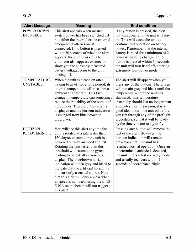
Alert Message Meaning End condition POWER DOWN IN 30 SECS.
This alert appears when master switch power has been switched off but either the internal or the external emergency batteries are still connected. If no button is pressed within 30 seconds of when the alert appears, the unit turns off. The voltmeter also appears onscreen to show you the currently measured battery voltages prior to the unit turning off.
If any button is pressed, the alert will disappear and the unit will stay on. This will cause the unit to continue full operation on battery power. Remember that the internal battery is rated for a minimum of 2 hours when fully charged. If no button is pressed within 30 seconds, the unit will turn itself off, entering extremely low-power mode.
TEMPERATURE UNSTABLE
When the unit is turned on after having been off for a long period, its internal temperature will rise above ambient at a fast rate. This fast change in temperature can sometimes reduce the reliability of the output of the sensors. Therefore, this alert is displayed and the horizon indication is changed from blue/brown to grey/black.
The alert will disappear when you press any of the buttons. The screen will remain grey and black until the temperature within the unit has stabilized. This temperature instability should last no longer than 2 minutes. For this reason, it is a good idea to turn the unit on before you run through any of the preflight procedures, so that it will be ready by the time you are ready to fly.
HORIZON RECOVERING…
You will see this alert anytime the unit is rotated at a rate faster than 150 degrees/second or the unit is powered on with airspeed applied. Rotating the unit faster than this threshold will saturate the gyros, leading to potentially erroneous display. The blue/brown horizon indication will turn grey and black to indicate that the artificial horizon is not currently a trusted source. Note that this alert will only appear when airspeed is non-zero; using the EFIS-D10A on the bench will not trigger this alert.
Pressing any button will remove the text of the alert. However, the horizon indication will remain grey/black until the unit has resumed normal operation. Once an indeterminate attitude is detected, the unit enters a fast recovery mode and usually recovers within 5 seconds of coordinated flight.

Appendix
6-4 EFIS-D10A Installation Guide
Alert Message Meaning End condition TIMER EXPIRE This alert appears when you have a
down timer enabled and it has reached 0. Additionally the up timer menu will display and the timer will flash the clock display, alerting you that the down timer has expired. See the Timer section in the EFIS-D10A Pilot’s User Guide
Pressing any button will remove the alert and stop the timer from flashing. However, you must press STOP in the Up Timer menu to stop the up timer. This allows you to see how much time has elapsed since the down timer has expired.
REMOTE COMPASS NOT DETECTED
The EFIS-D10A is unable to communicate with the EDC-D10A. If you have an OAT connected to your EDC-D10A, you will lose this reading, as well.
Ensure that you a) have an EDC-D10A installed and b) have verified that the wiring to the EDC-D10A is correct. Please see the EFIS-D10A Installation Guide for more information on verifying the installation of the EDC-D10A. This error also can appear if you have updated the firmware in your EFIS-D10A while the remote compass was not connected. If this is the case, try uploading the new firmware again with the EDC-D10A connected. Attempt the connection within the first few seconds of operation.
OAT SENSOR NOT DETECTED
This alert appears when the EFIS has an OAT connected and then loses that connection for some reason. Either the EDC-D10A has become disconnected, or the OAT sensor itself has become disconnected from the EDC-D10A.
Double-check your wiring between the EFIS-D10A and the EDC-D10A as well as that of the OAT sensor.
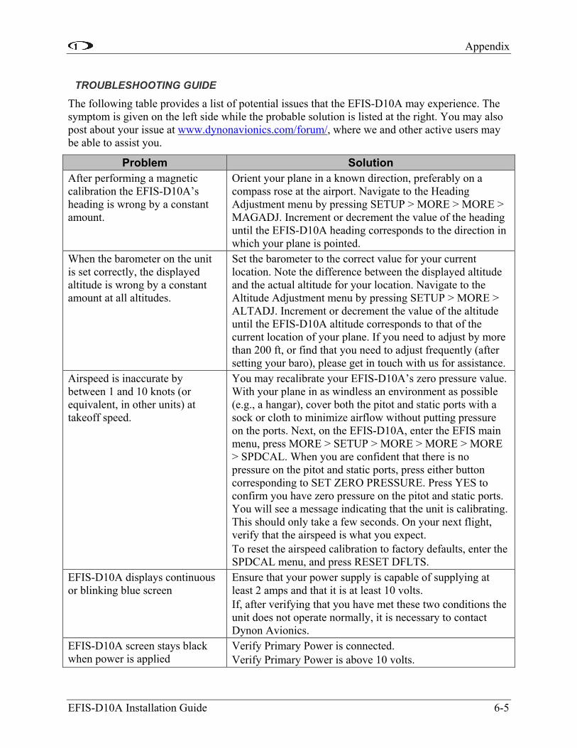
Appendix
EFIS-D10A Installation Guide 6-5
TROUBLESHOOTING GUIDE
The following table provides a list of potential issues that the EFIS-D10A may experience. The symptom is given on the left side while the probable solution is listed at the right. You may also post about your issue at www.dynonavionics.com/forum/, where we and other active users may be able to assist you.
Problem Solution After performing a magnetic calibration the EFIS-D10A’s heading is wrong by a constant amount.
Orient your plane in a known direction, preferably on a compass rose at the airport. Navigate to the Heading Adjustment menu by pressing SETUP > MORE > MORE > MAGADJ. Increment or decrement the value of the heading until the EFIS-D10A heading corresponds to the direction in which your plane is pointed.
When the barometer on the unit is set correctly, the displayed altitude is wrong by a constant amount at all altitudes.
Set the barometer to the correct value for your current location. Note the difference between the displayed altitude and the actual altitude for your location. Navigate to the Altitude Adjustment menu by pressing SETUP > MORE > ALTADJ. Increment or decrement the value of the altitude until the EFIS-D10A altitude corresponds to that of the current location of your plane. If you need to adjust by more than 200 ft, or find that you need to adjust frequently (after setting your baro), please get in touch with us for assistance.
Airspeed is inaccurate by between 1 and 10 knots (or equivalent, in other units) at takeoff speed.
You may recalibrate your EFIS-D10A’s zero pressure value. With your plane in as windless an environment as possible (e.g., a hangar), cover both the pitot and static ports with a sock or cloth to minimize airflow without putting pressure on the ports. Next, on the EFIS-D10A, enter the EFIS main menu, press MORE > SETUP > MORE > MORE > MORE > SPDCAL. When you are confident that there is no pressure on the pitot and static ports, press either button corresponding to SET ZERO PRESSURE. Press YES to confirm you have zero pressure on the pitot and static ports. You will see a message indicating that the unit is calibrating. This should only take a few seconds. On your next flight, verify that the airspeed is what you expect. To reset the airspeed calibration to factory defaults, enter the SPDCAL menu, and press RESET DFLTS.
EFIS-D10A displays continuous or blinking blue screen
Ensure that your power supply is capable of supplying at least 2 amps and that it is at least 10 volts. If, after verifying that you have met these two conditions the unit does not operate normally, it is necessary to contact Dynon Avionics.
EFIS-D10A screen stays black when power is applied
Verify Primary Power is connected. Verify Primary Power is above 10 volts.
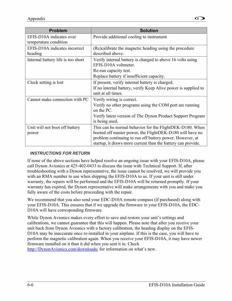
Appendix
6-6 EFIS-D10A Installation Guide
Problem Solution EFIS-D10A indicates over temperature condition
Provide additional cooling to instrument
EFIS-D10A indicates incorrect heading
(Re)calibrate the magnetic heading using the procedure described above.
Internal battery life is too short Verify internal battery is charged to above 16 volts using EFIS-D10A voltmeter. Re-run capacity test. Replace battery if insufficient capacity.
Clock setting is lost If present, verify internal battery is charged. If no internal battery, verify Keep Alive power is supplied to unit at all times.
Cannot make connection with PC Verify wiring is correct. Verify no other programs using the COM port are running on the PC. Verify latest version of The Dynon Product Support Program is being used.
Unit will not boot off battery power
This can be normal behavior for the FlightDEK-D180. When booted off master power, the FlightDEK-D180 will have no problem continuing to run off battery power. However, at startup, it draws more current than the battery can provide.
INSTRUCTIONS FOR RETURN
If none of the above sections have helped resolve an ongoing issue with your EFIS-D10A, please call Dynon Avionics at 425-402-0433 to discuss the issue with Technical Support. If, after troubleshooting with a Dynon representative, the issue cannot be resolved, we will provide you with an RMA number to use when shipping the EFIS-D10A to us. If your unit is still under warranty, the repairs will be performed and the EFIS-D10A will be returned promptly. If your warranty has expired, the Dynon representative will make arrangements with you and make you fully aware of the costs before proceeding with the repair.
We recommend that you also send your EDC-D10A remote compass (if purchased) along with your EFIS-D10A. This ensures that if we upgrade the firmware in your EFIS-D10A, the EDC-D10A will have corresponding firmware.
While Dynon Avionics makes every effort to save and restore your unit’s settings and calibrations, we cannot guarantee that this will happen. Please note that after you receive your unit back from Dynon Avionics with a factory calibration, the heading display on the EFIS-D10A may be inaccurate once re-installed in your airplane. If this is the case, you will have to perform the magnetic calibration again. When you receive your EFIS-D10A, it may have newer firmware installed on it than it did when you sent it in. Check http://DynonAvionics.com/downloads/ for information on what’s new.

Appendix
EFIS-D10A Installation Guide 6-7
Appendix B: Dynon OAT Probe Installation and Usage Note that this section only applies to the OAT with 3 wires (colored red, yellow, and blue), for connection to the EDC-D10A. If you have the 2-wire OAT (with black/white wires), see one of the EMS-based Installation Guides for more information.
The following instructions provide information on installing and using the EFIS-D10A OAT probe. Keep in mind that this probe is designed specifically to work with the EFIS-D10A. Do not expect it to work properly with another OAT or TAS/Density Altitude system. If you own an Dynon EMS product with an OAT installed, your EFIS-D10A can receive its OAT value from the EMS via the DSAB wires. See the Dynon Smart Avionics Bus (DSAB) Wiring section on page 3-11 for information on connecting the two instruments.
TOOLS AND MATERIALS REQUIRED
• Dynon Avionics OAT probe/cable with nylon nut and washer.
• Drill with 3/8” bit
• Dynon Avionics EDC-D10A remote compass module.
• 2 machined D-sub pins
• D-sub pin crimp tool
• Loctite
INSTALLATION
Mount Location
It is important that the OAT probe be mounted somewhere on the skin of the airplane where it will not be affected by heat sources (sun, engine, airplane interior, etc). It is acceptable to extend the length of the included wiring for the OAT. The ideal location would receive no heat from the aircraft engine or any other source in the airplane body. While this may be impractical, it is a good idea to mount the probe as far away from heat sources as possible. On the RV series, common locations include the wingtip and under the horizontal stabilizer.
Mounting Instructions
After the mounting location has been determined, drill a 3/8” hole in the skin at the desired location. Uncoil the cable attached to the OAT probe. String the nylon washer down the cable and over the threaded end of the OAT probe. From outside the skin of the airplane, insert the cable first and then the threaded end of the OAT probe. From within the skin of the airplane, gently pull the cable until the threaded end of the OAT probe pokes through the hole. Thread the nylon nut down the cable and up to the threaded end of the OAT probe. Spread some Loctite around the threads of the OAT probe. Twist the nut onto the threads of the OAT probe and tighten.
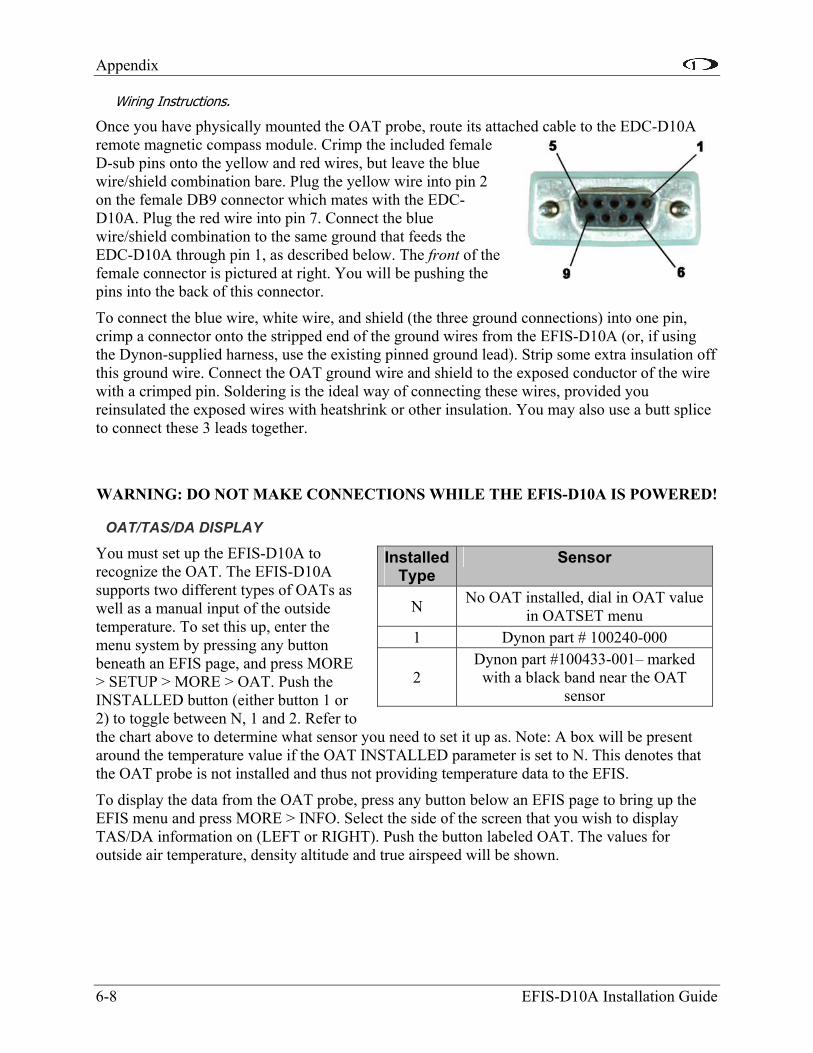
Appendix
6-8 EFIS-D10A Installation Guide
Wiring Instructions.
Once you have physically mounted the OAT probe, route its attached cable to the EDC-D10A remote magnetic compass module. Crimp the included female D-sub pins onto the yellow and red wires, but leave the blue wire/shield combination bare. Plug the yellow wire into pin 2 on the female DB9 connector which mates with the EDC-D10A. Plug the red wire into pin 7. Connect the blue wire/shield combination to the same ground that feeds the EDC-D10A through pin 1, as described below. The front of the female connector is pictured at right. You will be pushing the pins into the back of this connector.
To connect the blue wire, white wire, and shield (the three ground connections) into one pin, crimp a connector onto the stripped end of the ground wires from the EFIS-D10A (or, if using the Dynon-supplied harness, use the existing pinned ground lead). Strip some extra insulation off this ground wire. Connect the OAT ground wire and shield to the exposed conductor of the wire with a crimped pin. Soldering is the ideal way of connecting these wires, provided you reinsulated the exposed wires with heatshrink or other insulation. You may also use a butt splice to connect these 3 leads together.
WARNING: DO NOT MAKE CONNECTIONS WHILE THE EFIS-D10A IS POWERED!
OAT/TAS/DA DISPLAY
You must set up the EFIS-D10A to recognize the OAT. The EFIS-D10A supports two different types of OATs as well as a manual input of the outside temperature. To set this up, enter the menu system by pressing any button beneath an EFIS page, and press MORE > SETUP > MORE > OAT. Push the INSTALLED button (either button 1 or 2) to toggle between N, 1 and 2. Refer to the chart above to determine what sensor you need to set it up as. Note: A box will be present around the temperature value if the OAT INSTALLED parameter is set to N. This denotes that the OAT probe is not installed and thus not providing temperature data to the EFIS.
To display the data from the OAT probe, press any button below an EFIS page to bring up the EFIS menu and press MORE > INFO. Select the side of the screen that you wish to display TAS/DA information on (LEFT or RIGHT). Push the button labeled OAT. The values for outside air temperature, density altitude and true airspeed will be shown.
Installed Type
Sensor
N No OAT installed, dial in OAT value in OATSET menu
1 Dynon part # 100240-000
2 Dynon part #100433-001– marked
with a black band near the OAT sensor

Appendix
EFIS-D10A Installation Guide 6-9
CALIBRATION AND ADJUSTMENT
Before adjustment, it is possible for the OAT sensor to read as much as 5 degrees Celsius off the actual value. Therefore, it may be necessary to adjust the displayed air temperature value to compensate for this. To make this adjustment, you must enter the menu system and press the following sequence of buttons: MORE > SETUP > MORE > OAT. This will display the OAT adjustment menu. Press INC or DEC to increase or decrease the currently displayed OAT value.
It is important to make this adjustment when the air surrounding the OAT probe is at a known temperature. This can be achieved with a standard thermometer. Adjust the displayed OAT until it agrees with your independent temperature reference.
TROUBLESHOOTING
OAT value fluctuates wildly
If the OAT probe is improperly wired, the EFIS-D10A will not receive a valid signal from it. Verify that the three wires coming from the OAT probe are wired exactly as described in the Wiring Instructions section above.
OAT value is consistently high/low
You need to adjust the displayed OAT value to correct for sensor inaccuracies. Follow the instructions in the Calibration and Adjustment section above.
OAT display area states OAT NOT FOUND
Ensure that you have selected the number corresponding to your OAT in the OAT INSTALLED menu as described above. It can sometimes take as long as 5 seconds for the EFIS-D10A to lock onto the OAT reading. Ensure that all wiring is correct and that there are no shorted or open connections.
Other strange behavior by OAT reading
It is possible that your EFIS-D10A and EDC-D10A have mismatched versions of firmware on them. This most commonly happens when one takes the EFIS-D10A out of the airplane to connect to a computer for firmware upgrade. Ensure that the EFIS-D10A and EDC-D10A are connected to each other and communicating before attempting a firmware upgrade.

Appendix
6-10 EFIS-D10A Installation Guide
Appendix C: HS34 Installation and Configuration If you purchased an HS34 from Dynon Avionics, read through this section for details on its physical and electrical installation. It describes the pinout, mounting information, and some common wiring connections.
WIRING
Follow these instructions explicitly as improper wiring can result in permanent damage to your instrument, other connected equipment, or both. Read through the Recommended Wiring Practices section on page 2-1 before proceeding.
Harness Construction
Because the HS34 interfaces with such a wide variety of NAV radios and GPSs in different combinations of configurations, Dynon Avionics does not supply pre-manufactured harnesses for the HS34. Instead, your HS34 shipped with enough connectors and pins to generate a wide variety of harness configurations. Refer to the Pinouts and Function Description and Common Device Connections sections below for detailed wiring information.
If you do not own a D-sub machined-pin crimping tool, they can be obtained for under USD$50 at www.bandc.biz (p/n RCT-3), www.steinair.com (p/n SAT-004), and many other tool retailers. You may also find it helpful to own a pin insertion/extraction tool, part numbers DSE-1 and SAT-023, respectively.
Power Requirements
22 AWG wire is normally sufficient for the power supply and ground lines, but you should consult a wire sizing chart and determine the size required for your routing length. Make sure you protect the power lines with either a circuit breaker or an appropriately sized fuse for the wire you select. Power is fed to the HS34 via pins in the male DB25 connector on the back of the instrument.
The HS34’s power requirement is 2 watts typical and 3 watts maximum. On a 12-volt system, this translates to about 0.25 amps of maximum current draw. On a 24-volt system, this translates to about 0.13 amps maximum current draw. Normally, a 0.5-amp circuit breaker or fuse is sufficient.
Connector Description
The HS34 has two DB25 connectors on the rear of the instrument: one male and one female. All references to connector gender in this guide are used to describe the connectors on the back of the HS34, not your harnesses. When building harnesses for the HS34, make note of the fact that the pin order for the male connector is the opposite of the order for the female connector. Small pin numbers can be found next to each pin on both the instrument’s and harness’s connectors.

Appendix
Pinouts and Function Description
Below are the pinouts and function descriptions for the HS34’s male and female connectors. At a minimum, you must make the connections shown in the Universal Connections diagram. All other wiring connections depend on the external equipment you are connecting to the HS34. Many common radio and GPS connections are depicted in the Common Device Connections section below. Note that the pin numbers are labeled on the face of both the female and male connector.
Male (on HS34) DB25 Female (on HS34) DB25 Pin# Function Pin# Function
1 Serial 1 RX (PC updates & second serial port) 1 CDI + when deflected right
2 Serial 2 RX (SL30, GPS, etc) 2 VOR + when TO flag shown 3 DSAB A 3 LOC +
4 Primary Power (10-30V, 250 mA maximum at 12V) 4 GS + when up UP
5 GP Output 1 (not currently supported) 5 GS + when FLAG shown
6 GP Output 2 (not currently supported) 6 DME Analog IN (0-8V,
40mv/NM) 7 GP 1 in (same as EMS GP in) 7 Resolver B 8 GP 2 in (same as EMS GP in) 8 Resolver D 9 +5V out 9 Resolver F
10 GP 6 in (+15V GP in, not currently supported) 10 ARINC 429 RX 2 B
11 GP 5 in (+15V GP in, not currently supported) 11 ARINC 429 RX 1 B
12 GP 4 in (+15V GP in, not currently supported ) 12 ARINC 429 TX B
13 GP 3 in (same as EMS GP in) 13 ARINC 429 TX B 14 Serial 1 TX 14 CDI + when Left 15 Serial 2 TX 15 VOR + when From flag shown 16 DSAB B 16 LOC - 17 Primary Ground 17 GS + when Down 18 Contact in 4 (same as EMS contacts) 18 GS + when Flag hidden 19 Contact in 3 (same as EMS contacts) 19 Resolver A 20 Contact in 2 (same as EMS contacts) 20 Resolver C 21 Contact in 1 (same as EMS contacts) 21 Resolver E 22 Marker Outer Input 22 ARINC 429 RX 2 A 23 Marker Middle Input 23 ARINC 429 RX 1 A 24 Marker Inner Input 24 ARINC 429 TX A 25 Voice audio output (8V peak-peak) 25 ARINC 429 TX A
EFIS-D10A Installation Guide 6-11
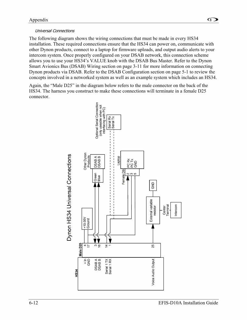
Appendix
6-12 EFIS-D10A Installation Guide
Universal Connections
The following diagram shows the wiring connections that must be made in every HS34 installation. These required connections ensure that the HS34 can power on, communicate with other Dynon products, connect to a laptop for firmware uploads, and output audio alerts to your intercom system. Once properly configured on your DSAB network, this connection scheme allows you to use your HS34’s VALUE knob with the DSAB Bus Master. Refer to the Dynon Smart Avionics Bus (DSAB) Wiring section on page 3-11 for more information on connecting Dynon products via DSAB. Refer to the DSAB Configuration section on page 5-1 to review the concepts involved in a networked system as well as an example system which includes an HS34.
Again, the “Male D25” in the diagram below refers to the male connector on the back of the HS34. The harness you construct to make these connections will terminate in a female D25 connector.

Appendix
Generic Device Connections
The three diagrams on this page depict generic device connections for devices outputting ARINC, serial, or analog data. If your device outputs multiple types of data, connect only one type to the HS34 in the following preference: ARINC preferred over serial; serial preferred over analog. ARINC data streams contain more information than serial streams and allow more control of your external device. Likewise, serial streams contain more information than that carried over analog lines. If your device is one of those listed in the next section, Common Device Connections, you may ignore this section.
EFIS-D10A Installation Guide 6-13

Appendix
Common Device Connections
The following several diagrams show some common radios and GPSs, and the preferred connection schemes between them and the HS34. Make note of whether the connections are to the male or female connector on the back of the HS34. When constructing your harness, refer to the pinouts on page 6-11.
6-14 EFIS-D10A Installation Guide
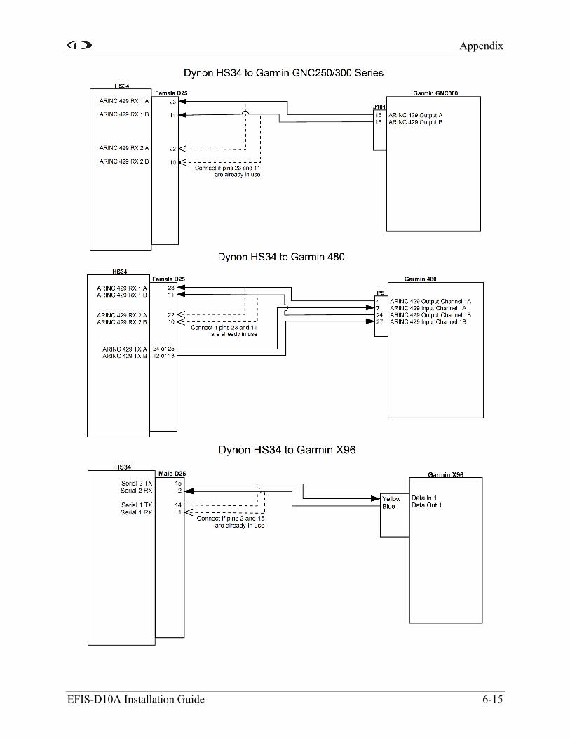
Appendix
EFIS-D10A Installation Guide 6-15

Appendix
6-16 EFIS-D10A Installation Guide
PANEL LOCATION AND MOUNTING
This section provides you with dimensions, panel location, and mounting information.
HS34 Dimensions and Panel Location
The diagram below shows the HS34’s outer dimensions. Note that the instrument extends about 3.7” behind the panel, and that harnesses can require up to three more inches. Use the dimensions (in inches) found on the diagram to plan for the space required by the instrument. The front bezel of the vertically oriented HS34 (100755-000) is the same height as Dynon’s D100-series products and can be mounted close to – or abutted against – one if desired. Plan a panel location that allows for convenient operation of the knobs and buttons. Ensure that the instrument is in a location where the light sensor (small circle of rubber at upper left of instrument) can measure the true ambient light conditions in the cabin.

Appendix
Mounting Tab Dimensions
The dimensions for the included mounting tab are below. Note that the tab does not extend behind the panel perpendicularly. This sharper angle causes the HS34 to pull itself against the panel when screwed into the tab.
HS34 Mounting
As shown in diagram at right, make a rectangular cutout – oriented either vertically or horizontally, depending on HS34 version ordered – of 1.45” by 4.75” (3.69 cm by 12.07 cm). Drill three holes at the locations specified in the diagram. Your HS34 also shipped with a life-sized mounting template for making this cutout and drilling the mounting tab holes. Secure the mounting tab to your panel in whatever way you desire. Riveting it to the panel is ideal, but drilling holes for mounting screws and nuts also works.
Upon securing the mounting tab to the back of your panel, slide the HS34 into it. Because the mounting tab does not extend behind the panel perpendicularly, the HS34 must slide into the panel such that only the top (or right, for the horizontal version) of the bezel meets the panel. The tapered mounting screw fits into the PEM nut at the end of the mounting tab. Use the included 7/64” Allen wrench to secure the mounting screw into the mounting tab. As you screw the mounting screw tighter, the bottom (or left, for the horizontal version) of the bezel moves closer to the panel. Once it touches the panel, do not turn the mounting screw any further.
EFIS-D10A Installation Guide 6-17

Appendix
6-18 EFIS-D10A Installation Guide
HS34 CONFIGURATION
This section guides you through configuring your HS34. Prior to beginning this section, you must have completed all the steps in the DSAB Configuration chapter with the HS34 turned on and connected to the DSAB network. After DSAB configuration, ensure that the HS34 appears as one of the ACTIVE devices in the EFIS > SETUP > DSAB > STATUS menu.
You may only configure your HS34 on the EFIS-based instrument assigned the DSAB Bus Master role. The following configuration steps are performed within the EFIS > SETUP > HSI menu on the Bus Master instrument.
Device Communication Setup
If you have connected a NAV radio to the analog pins shown in the Analog Connections diagram on page 6-13, enter the ANALOG menu to configure communication with this device. Press SEL to change the INPUT ENABLED to Y. The SYNCH OFFSET parameter is used to correct analog errors that can occur in the signal path between your radio and the HS34’s measurement. You may normally leave SYNCH OFFSET set to 0. However, if you observe errors in the green course pointer on the HSI Page, you – or a qualified avionics shop – may modify this parameter to bring the course pointer into agreement with the NAV radio. Set SYNCH OFFSET, in degrees, to a value equal to the number of degrees of error in the course pointer on the HSI Page.
If you have connected one or two devices outputting serial data, push DOWN to select the SERIAL menu, and SEL to enter it. If the device connected to the SERIAL 1 RX and TX pins is a GPS, set INPUT to either AVIATION or NMEA, and OUTPUT to NONE. If the device connected to the serial pins is a Garmin SL30 Nav/Comm, set INPUT to SL30 and OUTPUT to SL30 CMD. Set the BAUD RATE parameter to match the baud rate used by your SL30 or GPS. Many devices support more than one type of data format and baud rate; ensure that the INPUT and BAUD RATE settings for SERIAL 1 agree with the settings in the communication setup for the device connected to the HS34’s Serial 1 pins. If you have a second NAV radio or GPS connected to the Serial 2 pins, repeat the above steps for it.
If you have connected one or two devices outputting ARINC-429 data, push DOWN to select the ARINC-429 menu, and SEL to enter it. Set INPUT1 to the type of device connected to the HS34’s ARINC-429 RX 1 A and B inputs: GAMA GPS, GAMA NAV, or DME. If you have connected a device to ARINC-429 RX 2 A and B, repeat the above configuration for the INPUT2 parameter; otherwise, leave it set to NONE. Next set the SPEED parameter (HIGH or LOW), based on the output speed of your two ARINC devices. The HS34 has one ARINC output channel with 2 sets of pins on the connector for wiring convenience. If one or both of your ARINC devices can accept commands, set the OUTPUT DATA to ON and configure OUTPUT SPEED appropriately.
Note that the EFIS/EMS SERIAL menu is disabled on all products connected to a DSAB system with an HS34 connected. All GPS and NAV devices must be connected to the HS34.
Appendix
EFIS-D10A Installation Guide 6-19
Markers Configuration
The HS34 supports markers input via ARINC or the 3 discrete Inner, Middle, and Outer marker pins.
If your NAV radio outputs ARINC data whose stream contains marker information, set the SOURCE to either ARINC1 or ARINC2. ARINC1 corresponds to the ARINC-429 RX 1 A and B inputs (female DB25, pins 11 and 23). ARINC2 corresponds to the ARINC-429 RX 2 A and B inputs (female DB25, pins 10 and 22). You must also ensure that the corresponding INPUT1 or INPUT2 parameter in the ARINC-429 menu is set to GAMA NAV.
If you have a device which outputs marker data via 3 discrete signals, set the SOURCE to MRKR PINS. Ensure that your device’s Outer, Middle, and Inner outputs are connected to the HS34’s male DB25 pins 22, 23, and 24, respectively. Marker beacon receivers use a variety of techniques to output the 3 marker signals. Because of this, you may need to experiment with the PULL-UP and ACTIVE WHEN parameters. As a general rule of thumb, if the schematic for your receiver shows the 3 discrete outputs connected to lights whose other side is connected to power, set PULL-UP to Y and ACTIVE WHEN to LOW. Likewise, if the schematic shows the 3 discrete outputs connected to lights whose other side is connected to ground, set PULL-UP to N and ACTIVE WHEN to HIGH.
Regardless the input type used, you can configure the HS34 to output tones for Outer (Morse code “dashes”), Middle (Morse code “dot-dashes”), and Inner (Morse code “dots”) markers. Set TONES ACTIVE to Y to configure the HS34 to output the tones for each of the 3 markers. Set it to N to configure the HS34 to have no audible marker feedback.
DME Configuration
The HS34 supports Distance Measuring Equipment receiver input via ARINC or the single DME Analog In pin (female DB25, pin 6).
If you have connected a DME receiver which outputs ARINC data, set the SOURCE to either ARINC1 or ARINC2. ARINC1 corresponds to the ARINC-429 RX 1 A and B inputs (female DB25, pins 11 and 23). ARINC2 corresponds to the ARINC-429 RX 2 A and B inputs (female DB25, pins 10 and 22). You must also ensure that the corresponding INPUT1 or INPUT2 parameter in the ARINC-429 menu is set to DME.
If you have connected a DME receiver to the HS34’s DME Analog In pin, set the SOURCE to DME PIN.
GPS and NAV Display Order Configuration
Pressing the NAV SRC button on the HS34 cycles through the available NAV sources in the following order: DG, NAV1, NAV2, NAV N, GPS1, GPS2, GPS N. Of course, the numbers of NAVs and GPSs in the cycle depend on how many of each type are configured in the ANALOG, SERIAL, and ARINC-429 menus.
If you have configured more than one input to receive NAV radio data, enter the NAV ORDER menu to see the list of configured NAV radios and the HS34 inputs they are connected to. In this menu, you may change the order that each NAV input occurs within the NAV portion of cycle. If you do not see all expected NAV radios, verify that all settings are accurate in the ANALOG, SERIAL, and ARINC-429 menus. Press DOWN or UP to select the input that you wish to
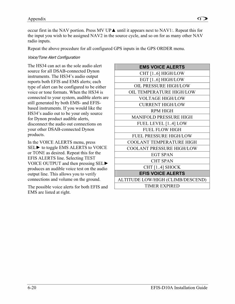
Appendix
occur first in the NAV portion. Press MV UP until it appears next to NAV1:. Repeat this for the input you wish to be assigned NAV2 in the source cycle, and so on for as many other NAV radio inputs.
Repeat the above procedure for all configured GPS inputs in the GPS ORDER menu.
Voice/Tone Alert Configuration
The HS34 can act as the sole audio alert source for all DSAB-connected Dynon instruments. The HS34’s audio output reports both EFIS and EMS alerts; each type of alert can be configured to be either voice or tone formats. When the HS34 is connected to your system, audible alerts are still generated by both EMS- and EFIS-based instruments. If you would like the HS34’s audio out to be your only source for Dynon product audible alerts, disconnect the audio out connections on your other DSAB-connected Dynon products.
EMS VOICE ALERTS CHT [1..6] HIGH/LOW EGT [1..6] HIGH/LOW
OIL PRESSURE HIGH/LOW OIL TEMPERATURE HIGH/LOW
VOLTAGE HIGH/LOW CURRENT HIGH/LOW
RPM HIGH MANIFOLD PRESSURE HIGH
FUEL LEVEL [1..4] LOW FUEL FLOW HIGH
FUEL PRESSURE HIGH/LOW COOLANT TEMPERATURE HIGH COOLANT PRESSURE HIGH/LOW
EGT SPAN CHT SPAN
CHT [1..4] SHOCK EFIS VOICE ALERTS
ALTITUDE LOW/HIGH (CLIMB/DESCEND) TIMER EXPIRED
In the VOICE ALERTS menu, press SEL to toggle EMS ALERTS to VOICE or TONE as desired. Repeat this for the EFIS ALERTS line. Selecting TEST VOICE OUTPUT and then pressing SEL produces an audible voice test on the audio output line. This allows you to verify connections and volume on the ground.
The possible voice alerts for both EFIS and EMS are listed at right.
6-20 EFIS-D10A Installation Guide

Appendix
EFIS-D10A Installation Guide 6-21
Appendix D: Dynon AOA/Pitot Installation and Calibration Thank you for your purchase of Dynon’s AOA/Pitot Probe. This guide walks you through the steps to install and calibrate both the heated and unheated versions of the AOA/Pitot Probe. While the probe senses standard pitot pressure, allowing it to work with any standard airspeed indicator, its AOA functionality is designed specifically to work with Dynon’s EFIS series of products. Do not expect it to work properly with another AOA system.
To ensure accuracy, it is very important that you install the probe correctly and perform the specified calibration steps. We recommend that you read the entire guide before proceeding with the installation.
Dynon’s Heated AOA/Pitot Probe is nickel-plated. Do not polish the probe as this will cause the finish to come off.
AOA CALCULATION: PRINCIPLES OF OPERATION
Dynon Avionics’ AOA/Pitot probe performs two functions: airspeed sensing and angle of attack sensing. These functions require two pressure ports on the tip of the probe. The normal pitot pressure port is on the front face of the probe and is designed to be insensitive to angle of attack. The second pressure port is located on an angled surface just under the pitot port and is designed to be very sensitive to AOA. The EFIS-D10A then uses the difference between these two pressures to calculate the current angle of attack.
HEATING: PRINCIPLES OF OPERATION
The heated version of Dynon’s AOA/Pitot Probe utilizes a heating mechanism unlike any other heated pitot on the market. The probe is heated by a high-quality nichrome heating element whose temperature is accurately measured and regulated by the heater controller. This controller – located in an enclosure which can be mounted in a wing or elsewhere – regulates the heat at the tip of the probe to a constant temperature. There are several advantages to this, including: lower power consumption, increased heating element lifespan, and a much cooler pitot on the ground when de-icing is not necessary. This unique technique ensures that the pitot can be rapidly de-iced when required, but does not needlessly waste electricity when not in icing conditions.
While the probe does not operate like a normal heated pitot, it will still get fairly hot in normal ambient temperatures. When turned on, it will regulate its internal temperature to about 70°C to 80°C. To ensure that the heater is working, briefly touch the end of the pitot farthest from the snout after 1 minute of operation and verify that it is warm.
FAILURE WARNING
Designed to meet the indication requirements of FAR 23.1326, the heated pitot controller has an output that can trigger a warning light in the cockpit whenever the probe heater is turned off or is not functioning properly. While not required for Experimental and LSA category aircraft, this feature provides peace of mind, giving you instant feedback that your probe’s heater is working as designed.
TOOLS AND MATERIALS REQUIRED
• Dynon Avionics AOA/Pitot probe.

Appendix
6-22 EFIS-D10A Installation Guide
• Two plumbing lines (usually ¼” soft aluminum or plastic tubing) routed from the EFIS-D10A to the probe mounting location.
• Adapters to interface with the 3/16” aluminum tubing from the probe to whatever plumbing lines are installed in the airplane (AN919-2D for 3/16 to ¼ , AN819-4D sleeve AN818-4D nut, AN819-3D sleeve, and AN818-3D nut)
• #36 Drill and 6-32 tap
• Mounting hardware (such as the Gretz Aero pitot mounting kit for the PH502-12CR or AN5812 pitot, available at http://aircraftspruce.com or http://www.gretzaero.com or http://www.safeair1.com)
o Examples of the mount installation could be found at: http://bmnellis.com/WingSkinning3.htm http://www.cafes.net/leo/RV-6/Pitot/Pitot.html
Please follow these instructions explicitly as improper installation can result in permanent damage to your device and/or aircraft.
HEATER CONTROLLER WIRING AND MOUNTING
If you have purchased the heated version of the probe, please follow the instructions in this section. If you have purchased the unheated version of the probe, you may skip to the AOA/Pitot Probe Mounting section on page 6-25. Please follow these instructions explicitly as improper installation can result in permanent damage to your device and/or aircraft.
Heater Controller Mounting
The heater controller box should ideally be mounted close to the AOA/Pitot Probe. The box’s dimensions are found at right, for reference. When mounting the controller close to the probe, ensure that it is close enough for its wires to mate with the probe’s, with room for strain-relief. If you find it difficult to mount the controller in the wing, or simply wish for the controller to be mounted closer to the battery, you must extend the lines using the correct wire gauge as described in the Wiring section below.
When the desired location is selected, secure the heater controller via the 4 mounting holes. Route the wiring between the probe, controller, panel, and power source, as described below.

Appendix
Heated AOA/Pitot Wiring System Overview
The following block diagram depicts the basic layout of the electrical connections between the probe and heater controller. This diagram should be used in conjunction with detailed instructions on the following pages. Read the specific instructions for each connection prior to installation.
EFIS-D10A Installation Guide 6-23
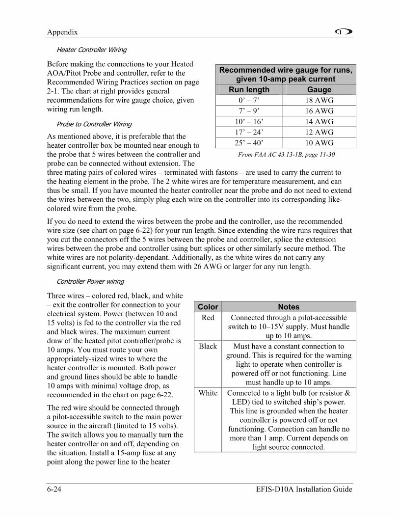
Appendix
Heater Controller Wiring
Before making the connections to your Heated AOA/Pitot Probe and controller, refer to the Recommended Wiring Practices section on page 2-1. The chart at right provides general recommendations for wire gauge choice, given wiring run length.
6-24 EFIS-D10A Installation Guide
Probe to Controller Wiring
As mentioned above, it is preferable that the heater controller box be mounted near enough to the probe that 5 wires between the controller and probe can be connected without extension. The three mating pairs of colored wires – terminated with fastons – are used to carry the current to the heating element in the probe. The 2 white wires are for temperature measurement, and can thus be small. If you have mounted the heater controller near the probe and do not need to extend the wires between the two, simply plug each wire on the controller into its corresponding like-colored wire from the probe.
Recommended wire gauge for runs, given 10-amp peak current
Run length Gauge 0’ – 7’ 18 AWG 7’ – 9’ 16 AWG
10’ – 16’ 14 AWG 17’ – 24’ 12 AWG 25’ – 40’ 10 AWG
From FAA AC 43.13-1B, page 11-30
If you do need to extend the wires between the probe and the controller, use the recommended wire size (see chart on page 6-22) for your run length. Since extending the wire runs requires that you cut the connectors off the 5 wires between the probe and controller, splice the extension wires between the probe and controller using butt splices or other similarly secure method. The white wires are not polarity-dependant. Additionally, as the white wires do not carry any significant current, you may extend them with 26 AWG or larger for any run length.
Controller Power wiring
Three wires – colored red, black, and white – exit the controller for connection to your electrical system. Power (between 10 and 15 volts) is fed to the controller via the red and black wires. The maximum current draw of the heated pitot controller/probe is 10 amps. You must route your own appropriately-sized wires to where the heater controller is mounted. Both power and ground lines should be able to handle 10 amps with minimal voltage drop, as recommended in the chart on page 6-22.
Color Notes Red Connected through a pilot-accessible
switch to 10–15V supply. Must handle up to 10 amps.
Black Must have a constant connection to ground. This is required for the warning
light to operate when controller is powered off or not functioning. Line
must handle up to 10 amps. White Connected to a light bulb (or resistor &
LED) tied to switched ship’s power. This line is grounded when the heater
controller is powered off or not functioning. Connection can handle no more than 1 amp. Current depends on
light source connected.
The red wire should be connected through a pilot-accessible switch to the main power source in the aircraft (limited to 15 volts). The switch allows you to manually turn the heater controller on and off, depending on the situation. Install a 15-amp fuse at any point along the power line to the heater
Appendix
EFIS-D10A Installation Guide 6-25
controller. Remember that even when the controller is powered on, it only heats the probe the amount necessary to maintain temperature.
The black wire should be permanently connected to ground. Cutting power to the heater controller should occur via the red power line, not the black ground line.
Heater Status Connection
Note: The probe heater functions properly whether or not you make this connection. It is simply a status output for your convenience.
The white heater status wire is grounded when the probe heater is turned off or not functioning properly. This wire should be connected to a light on the panel, whose other terminal is connected to switched aircraft power. When the heater is on and functioning properly, the white heater status line is open, leaving the indicator light turned off. When there is no power to the heater controller – or it is not functioning properly – the white line is grounded, turning the indicator light on.
Aircraft Spruce p/n 17-410 is an example of a light that will work for this application. An LED and resistor in series will also suffice. If you use an LED as the indicator, you must choose a resistor that delivers the appropriate current to the LED, and can accommodate the power required for its current and voltage drop.
If you own a Dynon EMS-based product, you may also use one of its two contact input to display an onscreen indication. Connect this heater status output directly to the desired EMS contact input, with no additional resistors or lights. You must configure the contact display as described in your EMS-based product’s Installation Guide.
AOA/PITOT PROBE MOUNTING
The Dynon Avionics AOA/Pitot probe has been designed as an under-wing pitot. The following information applies to this type of installation. If you wish to mount your pitot on nose boom mount, contact us so we can make the appropriate adjustments to your pitot. The heated version of Dynon’s AOA/Pitot Probe does not come in a boom-mount configuration.
AOA/Pitot Probe Mount Location
The Dynon Avionics AOA/Pitot probe only functions correctly when mounted in a location where the airflow over the probe is relatively undisturbed by the aircraft. In general, we recommend you mount it at least 6 inches below the wing and with the tip of the probe between 2 and 12 inches behind the leading edge of the wing. Typically, pitot probes are mounted about mid-wing span wise to minimize the effects of both the propeller and the wing tips. Testing during the probe development has shown that the standard mounting locations for the pitot probe in the RV series of aircraft also works for the Dynon probe.
AOA/Pitot Probe Mounting Instructions
After the mounting location has been determined, mount the pitot mounting kit per the included instructions or fabricate your own mount. In either case, mount the probe securely to the wing such that the body of the probe is horizontal during level flight. Drill and tap mounting holes (# 6-32) on the probe to match your mounting bracket. Use caution when drilling the holes, ensuring that you avoid drilling into the pitot and AOA pressure lines. As long as you do not

Appendix
penetrate these lines, you may drill all the way through the outer metal without affecting the probe’s waterproofing.
DIMENSIONS
Standard mount
6-26 EFIS-D10A Installation Guide
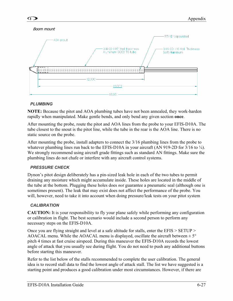
Appendix
Boom mount
PLUMBING
NOTE: Because the pitot and AOA plumbing tubes have not been annealed, they work-harden rapidly when manipulated. Make gentle bends, and only bend any given section once.
After mounting the probe, route the pitot and AOA lines from the probe to your EFIS-D10A. The tube closest to the snout is the pitot line, while the tube in the rear is the AOA line. There is no static source on the probe.
After mounting the probe, install adapters to connect the 3/16 plumbing lines from the probe to whatever plumbing lines run back to the EFIS-D10A in your aircraft (AN 919-2D for 3/16 to ¼). We strongly recommend using aircraft grade fittings such as standard AN fittings. Make sure the plumbing lines do not chafe or interfere with any aircraft control systems.
PRESSURE CHECK
Dynon’s pitot design deliberately has a pin-sized leak hole in each of the two tubes to permit draining any moisture which might accumulate inside. These holes are located in the middle of the tube at the bottom. Plugging these holes does not guarantee a pneumatic seal (although one is sometimes present). The leak that may exist does not affect the performance of the probe. You will, however, need to take it into account when doing pressure/leak tests on your pitot system
CALIBRATION
CAUTION: It is your responsibility to fly your plane safely while performing any configuration or calibration in flight. The best scenario would include a second person to perform any necessary steps on the EFIS-D10A.
Once you are flying straight and level at a safe altitude for stalls, enter the EFIS > SETUP > AOACAL menu. While the AOACAL menu is displayed, oscillate the aircraft between ± 5° pitch 4 times at fast cruise airspeed. During this maneuver the EFIS-D10A records the lowest angle of attack that you usually see during flight. You do not need to push any additional buttons before starting this maneuver.
Refer to the list below of the stalls recommended to complete the user calibration. The general idea is to record stall data to find the lowest angle of attack stall. The list we have suggested is a starting point and produces a good calibration under most circumstances. However, if there are
EFIS-D10A Installation Guide 6-27

Appendix
6-28 EFIS-D10A Installation Guide
flight regimes not listed that you suspect would create stalls at lower angle of attack it would be good to record those as well.
• With full power, no flaps • With no power, no flaps • With full power, full flaps • With no power, full flaps
Push the STALL button before performing each stall. When you push the STALL button, a 45-second timer starts. Notice the “T” next to the time that is counting down. During the 45 seconds that the timer is counting down, you are expected to have completed the stall maneuver. If any stall maneuver is not completed before the timer expires, the calibration will be invalid, and should be reset. To do this, push the CANCEL button. This exits the AOACAL menu; re-enter it to begin the calibration again. After completing the stall, make sure you let the 45 second timer count down to 0 before you push the STALL button for the next stall. When the listed stall maneuvers have been completed according to the above procedure, push FINISH. At this point, the AOA indicator has been calibrated. If it is not visible, turn the display on in the EFIS > SETUP > CLUTTR > AOABAR menu. This calibration should result in the lowest angle of attack stall occurring just above the red/yellow boundary. If this is not the case, please repeat the AOA user calibration, including flight configurations that resulted in stalls with incorrect indications. If the user calibration continues to be unsuccessful, please contact Dynon Avionics technical support.
ALARM SETUP
Enter the EFIS > SETUP > AOAALM menu and press any of the buttons beneath the AUDIO label to select the point on the AOA bar at which you wish the alarm to sound. Some of the alarms – the ones that begin with START – are progressive, meaning the audio alert gets more intense as your angle of attack increases. You may set these progressive alarms to start at the top, middle, or bottom of the yellow section of the AOA bar. Setting AUDIO to ON IN RED configures an intense alarm to occur only when the AOA indicator is in the red.
To reduce nuisance audible AOA alarms – such as when taxiing, taking off and landing – the alarm can be inhibited below a selected airspeed. While in the EFIS > SETUP > AOAALM menu, press MINSPD to configure the minimum airspeed at which an AOA alarm can occur. Anytime airspeed is below the MINSPD value, AOA alarms will not occur; anytime it is above the MINSPD value, alarms can occur. If the AOA alarm is already sounding as airspeed falls below this threshold, it will continue to sound until the high AOA condition is resolved.
Appendix
EFIS-D10A Installation Guide 6-29
Appendix E: Encoder Serial-to-Gray Code Converter Installation
INTRODUCTION AND DESCRIPTION
The Encoder Converter is an electronic device that receives the serial encoder data from the EFIS-D10A and outputs standard Mode-C parallel Gray code into your Mode-C transponder. This Encoder Converter requires data from the EFIS-D10A and is not to be confused with other standalone encoders available on the market. While the installation is not complex, it is important that you install the unit correctly. The Encoder Converter does not output an encoder strobe signal.
The Encoder Converter is designed to be powered off voltages between 10 and 30 volts.
TOOLS AND EQUIPMENT
The following parts are not included with your Encoder Converter purchase but may be necessary to complete the installation.
• Wire cutters
• Connector crimp tool
• Crimp pins
• 25-pin EFIS harness to mate with EFIS-D10A (may have been purchased with your EFIS-D10A)
• Connector to mate with Gray code transponder
ELECTRICAL INSTALLATION
The following section describes the wiring requirements for using the Encoder Converter. Please follow these instructions explicitly as improper wiring can result in permanent damage to your unit.
RECOMMENDED WIRING PRACTICES
NOTE: Use correct splicing techniques for all electrical connections, taking care to properly insulate any exposed wire. A short circuit between any of the wires may cause damage to the Encoder.
The wire used in construction of your Encoder Converter is 22 gauge avionics grade Tefzel wire, which meets Mil Standard MIL-W-22759/16.
Installing: Make sure all connections are secure and all wires are routed and strain relieved to ensure that the wires will not chafe against any other object in the aircraft.
STEP 1: TRANSPONDER WIRING
Wire the Encoder Converter signals to their respective connections on your Mode-C transponder. Mode-C transponder pin-outs vary from device to device. To find the correct pin-out, look at the manual for your transponder or contact its manufacturer. The table below details which color wire should be connected to each Transponder pin. All of the wires listed in the table leave one

Appendix
6-30 EFIS-D10A Installation Guide
end of the Encoder Converter in a single bundle. If your transponder has a switched power output, connect this to the power inputs on the Encoder Converter. If your transponder does not include this switched power output, the Encoder Converter power connections should be made directly to your switched avionics power. Ensure that all avionics power is off before performing the wiring step of this installation.
If your Altitude Transponder has either a strobe signal or a D4 pin, leave these pins unconnected.
Transponder Pin Encoder Converter Wire Color
A1 Yellow
A2 Green
A4 White with Blue
B1 Blue
B2 Orange
B4 White with Red
C1 White with Green
C2 White
C4 White with Black
Power (10V-30V) Red
Gnd Black
Strobe Signal No Connection
The Gray code output of the Encoder Converter reports altitude not adjusted for barometric pressure, as required by FAA specification. The altitude reported by the EFIS-D10A encoder will always match the altitude shown on screen when the BARO value is set to 29.92 inHg.
STEP 2: CONNECTING TO THE EFIS-D10A
Before wiring connections to the EFIS-D10A check to ensure that the wire length between your Encoder Converter and your EFIS-D10A is appropriate. Add or remove wire length if needed or desired. Customizing the wire length will facilitate an installation that is both cleaner and more secure.
The only pins of interest on the EFIS-D10A connector for the Encoder Converter installation are pins 13 and 21. The two wires exiting the Encoder Converter are the EFIS-TX and the EFIS-Ground, which are green (or red) and black respectively, and 2 feet in length. Connect these wires to the EFIS-D10A 25-pin female harness.
Ensure that your EFIS-D10A is powered off. Then connect the black EFIS Ground wire to pin 21. Then, connect the green wire to pin 13 (Serial Encoder Transmit) on the EFIS harness.
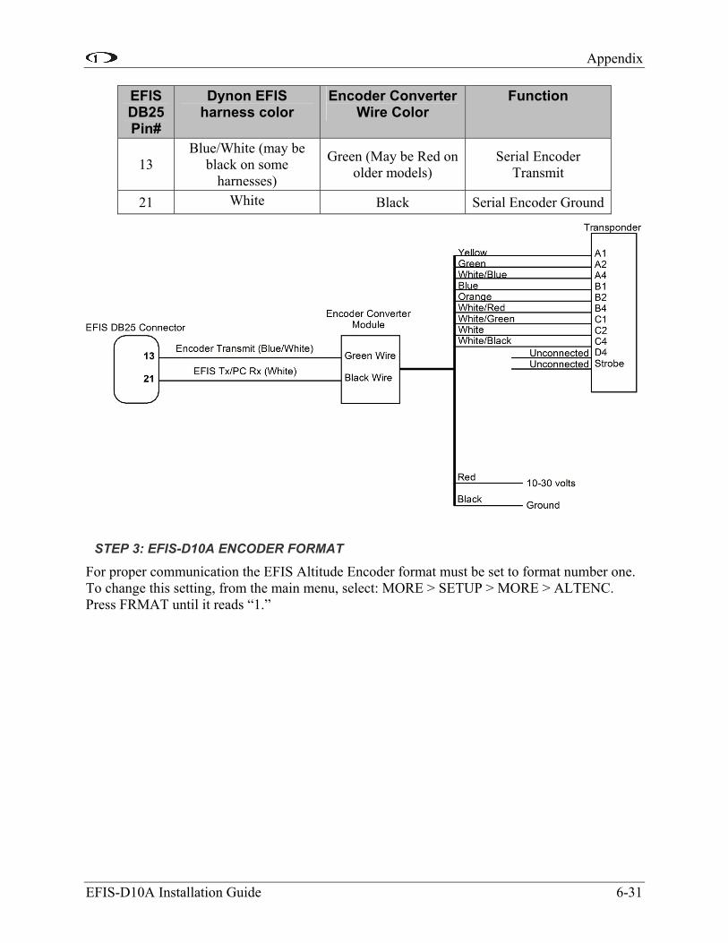
Appendix
EFIS-D10A Installation Guide 6-31
EFIS DB25 Pin#
Dynon EFIS harness color
Encoder Converter Wire Color
Function
Blue/White (may be black on some
harnesses)
Green (May be Red on older models)
Serial Encoder Transmit 13
White 21 Black Serial Encoder Ground
STEP 3: EFIS-D10A ENCODER FORMAT
For proper communication the EFIS Altitude Encoder format must be set to format number one. To change this setting, from the main menu, select: MORE > SETUP > MORE > ALTENC. Press FRMAT until it reads “1.”
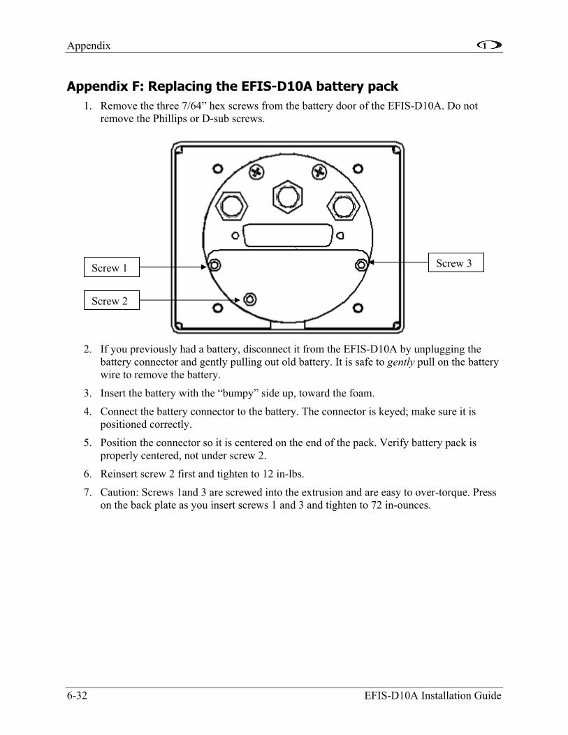
Appendix
6-32 EFIS-D10A Installation Guide
Appendix F: Replacing the EFIS-D10A battery pack 1. Remove the three 7/64” hex screws from the battery door of the EFIS-D10A. Do not
remove the Phillips or D-sub screws.
2. If you previously had a battery, disconnect it from the EFIS-D10A by unplugging the battery connector and gently pulling out old battery. It is safe to gently pull on the battery wire to remove the battery.
3. Insert the battery with the “bumpy” side up, toward the foam.
4. Connect the battery connector to the battery. The connector is keyed; make sure it is positioned correctly.
5. Position the connector so it is centered on the end of the pack. Verify battery pack is properly centered, not under screw 2.
6. Reinsert screw 2 first and tighten to 12 in-lbs.
7. Caution: Screws 1and 3 are screwed into the extrusion and are easy to over-torque. Press on the back plate as you insert screws 1 and 3 and tighten to 72 in-ounces.
Screw 1
Screw 2
Screw 3

Appendix
EFIS-D10A Installation Guide 6-33
Appendix G: Weights Adding any new instrument to an airplane requires the installer to be aware of its weight and how that affects the overall weight and balance of the plane. The following are the weights of the EFIS-D10A and associated Dynon-supplied sensors.
EFIS-D10A ........................................................................................................1 lb 9 oz (0.709 kg)
EFIS-D10A + battery.......................................................................................1 lb 15 oz (0.879 kg)
EFIS 25-pin wiring harness ...................................................................................11.2 oz (0.32 kg)
EDC-D10A ............................................................................................................3.6 oz (0.102 kg)
EFIS OAT ................................................................................................................3.2 oz (0.08 kg)
Heated AOA/Pitot Probe & Heater Controller ......................................................11.2 oz (0.32 kg)
Unheated AOA/Pitot Probe......................................................................................5.6 oz (0.16 kg)
Appendix H: EFIS-D10A Specifications
Mechanical Fits into standard 3 1/8” panel hole Optional flush mount bracket available
Operating Temperature -22° to 122° F (-30° to 50° C)
Power Voltage: 10 - 30 Vdc Power: 8 watts typical; 13 watts maximum
Connections Wiring: DB25 male connector
Screen
Type: AMLCD, TFT (Thin Film Transistor) Backlight: 450 nits Size: 3.8” diagonal (96 mm) Resolution: 320 x 240 color pixels
Inputs/Outputs
1 - AOA Audio Alarm 1 - RS-232 bidirectional PC communication 1 - RS-232 data inputs (GPS, SL30, etc.) 1 - RS-232 serial encoder output 1 - Dynon Smart Avionics Bus (DSAB) multidrop