,eil,, - galco.com · ,eil,, e196364 1500 va al30'c. amb. 1000 va a155"c. amb. bs.,...
TRANSCRIPT

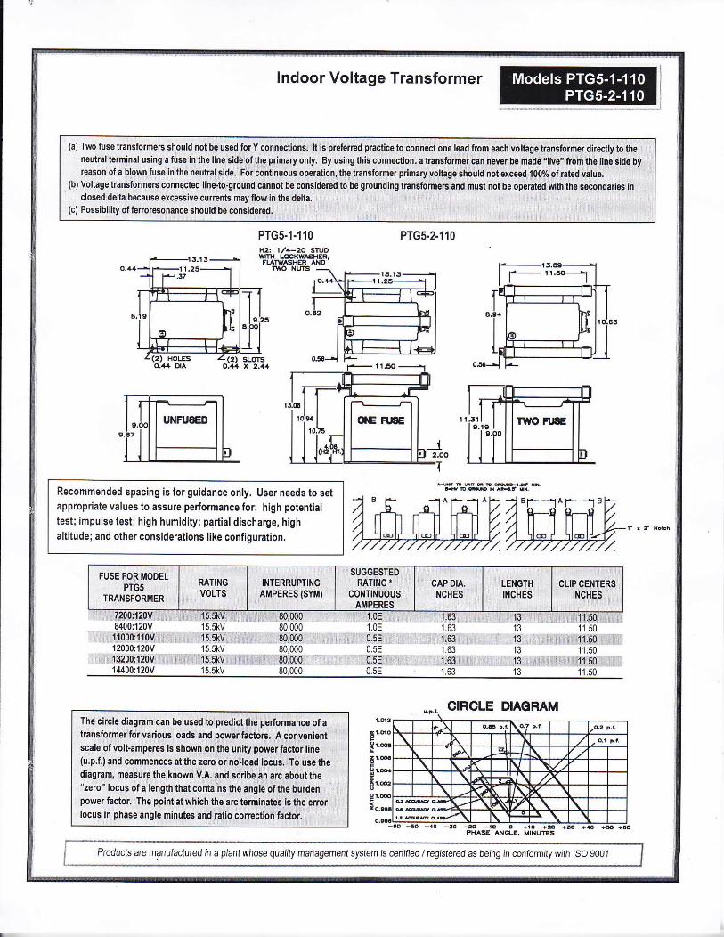
Crompton I ndoor Voltage Transformer
A3 V/XMYZ,l.2ZZ a|100% rated voltage with '120V basedANSI burden; 0.3 WXMY, 1.22 at 58% rated voltage with69.3V based ANSL burden
@@60 Hz.
fiITIIfiIIIiI:ESETIEXI'I'IIIETE15.5kV BIL 11okv fullwave
,EIl,,E196364
1500 VA al30'C. amb.
1000 VA a155"C. amb.
bs., unfused
Primary lermifals that are unfused are % - 20 brass screws with one flatwasher and ockwasher, un ess otherwise speciited.Pr mary terminals that are fused are % - 20 brass screws with one flatwasher lockwasher and lwo nuls.
Secondary terrnlnals are No. 10-32 brass screws wlth one flat washerand lockwasher.
The core and co I assembly s vacuum encapsulaled in polyurethane
resin.
Therma burden rating ls for 120 volt secondariesPlated steeL mounting base.
Fuses have 1.63" Dia Caps and 11.50" c|ip centers.
Swtchgear stye ls similar to fused style. Nofuseorfuseclipisprovided, but inseds for flse c ips are supplied.
A test cord is provided wilh each unit.
H1 H2 ca
'[lTIYO FTJSE OIE FUSE
.t.x1 x2
UNFUSED
1-110-722F PTG5-1-184.00 70.1
11000 '100:1
12004 ., .. 100:1
13200 11011
PrG5-1-1'10.842FPTG5-1-110-113F
PTGs-1.110.123FPTG5-1 -1 '1 0-1 322F PTGs-1-1 r 0-1322C
TWO BUSHING NU[/1BERS
1
1 ..2
22
Producls are manufactured in a plant whose qualty management system is cerlified / registered as being in mnformity with ISO gO01
lndoor Voltage Transformer
PTGs.1.110 PTG5.2.110
Recommended spacing is for guidance only. User needs to setappropriate values to assure performance lor: high potential
test; impulse test; high humidity; parlial discharge, highaltitude; and other considerations like configuration.
Ptoducts are manufactured in a planl whose qualily management system is @ttified / registeted as being in conformity with lso 9001
(a)Two fusetransforme6 should mt be lsed forY connections. lt is preferred practice lo connect one lead lrom each voltage transformet dkes{ly to theneutral terminal usirg a fuse irlhe line sidsofthe primaryonly. By using this colnection. a fanslormer caB never be made,'live" from thi line gide byreason ofa blown fuse in the neutralside. Forcontinuous opention,lhe kansfomer p mary voltage should not exceed 100% of rated value.
(b) Voltage transfo rmers connected line-to-ground cannot b€ considered to be grounding transformeE and must not be op€rated with the secondaries i.lclosed delta because ercessive currents may rlow in the delta.
(c) Possibility ofterroresonance should be considered.
The circle diagram can be used to predict the performance ofatransformer for va rious loads and power factorE. A convenientscale ofvolt amperes is shoi,yn on the unity power faclor line(u,p.f,) and commences at the zero or no.load locus. To use thediagram, measure the known V-A. and scribe En arc about the-zero" locus of a length that contains the angle ofthe burdenpower factor, The ppintatwhich the arc temirates is lhe erorlocus in phase angle minutes and ratio coneclion hclor.