ek307a1 f17 lecture17 rev2 - boston...
TRANSCRIPT

EK 307:Electric Circuits
Fall 2017
Lecture 17Nov 7, 2017
Hayk GevorgyanDepartment of Electrical and Computer Engineering
Boston University

Last time (Lecture 16):
• First-‐order circuits• Source-‐free RC and RL circuits• Singularity functions to represent step responses• Discussed a driven RC circuit
(covered Sections 7.1-‐7.4 and a little of 7.5)

Singularity functions: unit step, delta, ramp


Lecture 17: Chapter 7: 1st order ccts
1. Driven RC and RL circuits2. First-‐order op-‐amp circuits
(covering sections 7.5-‐7.7)

Step response

From last time: discussed physical intuition
Representation using switch:
Representation using unit step function

Solving for the step responseWe write Kirchhoff’s current law

Solving for the step response
This is known as the complete (or total) response of circuit to sudden turn-‐on of DC voltage source, assuming capacitor is initially charged.

Solving for the step response
Assuming that Vs > V0:

Solving for the step response
Assuming that Vs > V0:
If capacitor is uncharged initially, then V0 = 0 and
or

Solving for the step response
If capacitor uncharged initially, then V0 = 0 and
or
Current:
or
Voltage response Current response
i(t)

Systematic shortcut method for step response of RC/RL circuit
Voltage response
i(t)
Picture 1: Break down into natural and forced response

Systematic shortcut method for step response of RC/RL circuit
Voltage response
i(t)
Picture 2: Break down into transient + steady state responses

Systematic shortcut method for step response of RC/RL circuit
Voltage response
i(t)
Picture 2: Break down into transient + steady state responses

Systematic shortcut method for step response of RC/RL circuit
i(t)
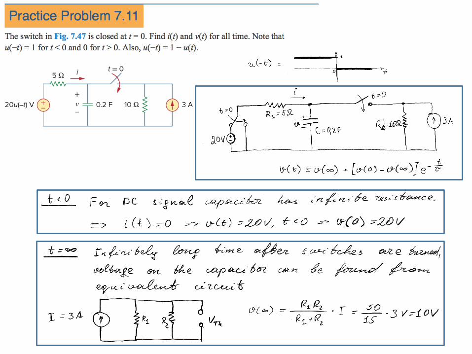
Either way, can write response for t>0 as:
v(0)
v(∞) To find step response of RC circuit need 3 things:
1. Initial capacitor voltage, v(0)2. Final capacitor voltage, v(∞)3. Time constant, τ
(Get #1 from cct at t<0, and #2,#3 from cct at t>0)
(For the capacitor voltage!)


-‐


Step Response of RL Circuits
Same as RC, but here response is for inductor current (it’s always the variable that stores energy – ½Cv2 for cap, ½Li2 for inductors)

Step Response of RL Circuits

-‐


First-‐order op-‐amp circuits
• Op-‐amp cct containing a storage element (C or L)• Differentiators and integrators, already covered before, are examples of first-‐order op amp ccts• For practical reasons, inductors are hardly ever used in op amp circuits because they are large.• Therefore, the op amp circuits we consider here are of the RC type.


