elcometer 236 dc holiday detector operating instructions
TRANSCRIPT
Eng
lish
236_TMA_0214_00_04 A6L.fm Page -1 Monday, January 19, 2009 2:25 PM
Elcometer 236
DC Holiday Detector
Operating Instructions
Eng
lish
R
The extreThe whileFor s
the first time - se
The ElcoHoweverat the pro
electronic apparadistance of 3 m wIt is therefore recthe User does no
All other tradema© Copyright Elco
All rights reserveotherwise) or tranotherwise) withou
A copy of this Ins
236_TMA_0214_00_04 A6L.fm Page 0 Monday, January 19, 2009 2:25 PM
Safety Warningdetector generates a high voltage at the probe tip up to 30,000 volts. The equipment should be used withme care, following the instructions given in this Manual.detector is powered by a rechargeable battery and the instrument must not be used for high voltage testing connected to the mains electricity supply for battery charging.afety and reliability the detector is supplied with the battery discharged. Recharge the battery before using fore “Charging the battery” on page 35.
meter 236 DC Holiday Detector meets the emc directive 89/336/EEC, amended 92/31/EEC and 93/68/EEC., due to its method of operation, the Detector will generate broad band RF emissions when a spark is producedbe, i.e., when a defect in the coating is located. These emissions may interfere with the operation of sensitivetus in the vicinity. In the extreme case of a continuous spark of length 5 mm, the magnitude of emissions at aas found to be approximately 60 dBµV/m from 30 MHz to 1000 MHz.ommended that this equipment is not operated within 30 m of known sensitive electronic equipment and thatt deliberately generate continuous sparks.
is a registered trademark of Elcometer Limited.rks acknowledged.meter Limited. 2009.
d. No part of this Document may be reproduced, transmitted, transcribed, stored (in a retrieval system orslated into any language, in any form or by any means (electronic, mechanical, magnetic, optical, manual ort the prior written permission of Elcometer Limited.
truction Manual is available for download on our Website via www.elcometer.com/downloads.Doc No. TMA–0214 Issue 04
Text with Cover No. 4885
R
1
Page
. . . . . . . . . . . . . . . . . . . . . . . . 4
. . . . . . . . . . . . . . . . . . . . . . . . 4
. . . . . . . . . . . . . . . . . . . . . . . . 5
. . . . . . . . . . . . . . . . . . . . . . . . 7
. . . . . . . . . . . . . . . . . . . . . . . . 7
. . . . . . . . . . . . . . . . . . . . . . . . 7
. . . . . . . . . . . . . . . . . . . . . . . . 8
. . . . . . . . . . . . . . . . . . . . . . . 11
. . . . . . . . . . . . . . . . . . . . . . . 11
. . . . . . . . . . . . . . . . . . . . . . . 12
. . . . . . . . . . . . . . . . . . . . . . . 13
. . . . . . . . . . . . . . . . . . . . . . . 14
. . . . . . . . . . . . . . . . . . . . . . . 15
. . . . . . . . . . . . . . . . . . . . . . . 16
. . . . . . . . . . . . . . . . . . . . . . . 16
. . . . . . . . . . . . . . . . . . . . . . . 16
. . . . . . . . . . . . . . . . . . . . . . . 16
. . . . . . . . . . . . . . . . . . . . . . . 17
. . . . . . . . . . . . . . . . . . . . . . . 17
236_TMA_0214_00_04 A6L.fm Page 1 Monday, January 19, 2009 2:25 PM
CONTENTS
Section
1 About this holiday detector . . . . . . . . . . . . . . . . . . . . . . . . . . . . . . . . 1.1 What the box contains. . . . . . . . . . . . . . . . . . . . . . . . . . . . . . . . . . . . . .
2 Working safely. . . . . . . . . . . . . . . . . . . . . . . . . . . . . . . . . . . . . . . . . . .
3 Holiday detection . . . . . . . . . . . . . . . . . . . . . . . . . . . . . . . . . . . . . . . . 3.1 The need for holiday detection . . . . . . . . . . . . . . . . . . . . . . . . . . . . . . . 3.2 How your detector works. . . . . . . . . . . . . . . . . . . . . . . . . . . . . . . . . . . .
4 Standards and test methods . . . . . . . . . . . . . . . . . . . . . . . . . . . . . . .
5 Getting started. . . . . . . . . . . . . . . . . . . . . . . . . . . . . . . . . . . . . . . . . . . 5.1 The control panel . . . . . . . . . . . . . . . . . . . . . . . . . . . . . . . . . . . . . . . . . 5.2 Connections and terminals . . . . . . . . . . . . . . . . . . . . . . . . . . . . . . . . . . 5.3 The probe handle . . . . . . . . . . . . . . . . . . . . . . . . . . . . . . . . . . . . . . . . . 5.4 The carry case . . . . . . . . . . . . . . . . . . . . . . . . . . . . . . . . . . . . . . . . . . . 5.5 Quick start guide . . . . . . . . . . . . . . . . . . . . . . . . . . . . . . . . . . . . . . . . . .
6 Using the Holiday Detector . . . . . . . . . . . . . . . . . . . . . . . . . . . . . . . . 6.1 Test batteries . . . . . . . . . . . . . . . . . . . . . . . . . . . . . . . . . . . . . . . . . . . . 6.2 Connect leads . . . . . . . . . . . . . . . . . . . . . . . . . . . . . . . . . . . . . . . . . . . . 6.3 Select probe . . . . . . . . . . . . . . . . . . . . . . . . . . . . . . . . . . . . . . . . . . . . . 6.4 Connect high voltage return to substrate . . . . . . . . . . . . . . . . . . . . . . . 6.5 Check operation of high voltage return connection. . . . . . . . . . . . . . . .

. . . . . . . . . . . . . . . . . . . . . . . 18
. . . . . . . . . . . . . . . . . . . . . . . 18
. . . . . . . . . . . . . . . . . . . . . . . 18
. . . . . . . . . . . . . . . . . . . . . . . 18
. . . . . . . . . . . . . . . . . . . . . . . 19
. . . . . . . . . . . . . . . . . . . . . . . 19
. . . . . . . . . . . . . . . . . . . . . . . 21
. . . . . . . . . . . . . . . . . . . . . . . 21
. . . . . . . . . . . . . . . . . . . . . . . 22
. . . . . . . . . . . . . . . . . . . . . . . 22
. . . . . . . . . . . . . . . . . . . . . . . 24
. . . . . . . . . . . . . . . . . . . . . . . 25
. . . . . . . . . . . . . . . . . . . . . . . 25
. . . . . . . . . . . . . . . . . . . . . . . 28
. . . . . . . . . . . . . . . . . . . . . . . 30
. . . . . . . . . . . . . . . . . . . . . . . 30
. . . . . . . . . . . . . . . . . . . . . . . 31
. . . . . . . . . . . . . . . . . . . . . . . 31
. . . . . . . . . . . . . . . . . . . . . . . 32
. . . . . . . . . . . . . . . . . . . . . . . 34
. . . . . . . . . . . . . . . . . . . . . . . 34
. . . . . . . . . . . . . . . . . . . . . . . 36
236_TMA_0214_00_04 A6L.fm Page 2 Monday, January 19, 2009 2:25 PM
R
2
6.6 Set test voltage . . . . . . . . . . . . . . . . . . . . . . . . . . . . . . . . . . . . . . . . . . . 6.7 Set alarm sensitivity . . . . . . . . . . . . . . . . . . . . . . . . . . . . . . . . . . . . . . . 6.8 Check for correct operation. . . . . . . . . . . . . . . . . . . . . . . . . . . . . . . . . . 6.9 Inspect coating for flaws . . . . . . . . . . . . . . . . . . . . . . . . . . . . . . . . . . . . 6.10Moving work position and finishing work . . . . . . . . . . . . . . . . . . . . . . .
7 Static electricity. . . . . . . . . . . . . . . . . . . . . . . . . . . . . . . . . . . . . . . . . .
8 Using the current monitoring function . . . . . . . . . . . . . . . . . . . . . . . 8.1 Breakdown voltage operation outline . . . . . . . . . . . . . . . . . . . . . . . . . .
9 Setting the test voltage and sensitivity. . . . . . . . . . . . . . . . . . . . . . . 9.1 Dielectric strength . . . . . . . . . . . . . . . . . . . . . . . . . . . . . . . . . . . . . . . . . 9.2 Establishing the Voltage Limits . . . . . . . . . . . . . . . . . . . . . . . . . . . . . . . 9.3 Setting the test voltage . . . . . . . . . . . . . . . . . . . . . . . . . . . . . . . . . . . . . 9.4 Setting alarm sensitivity . . . . . . . . . . . . . . . . . . . . . . . . . . . . . . . . . . . .
10 Probe selection . . . . . . . . . . . . . . . . . . . . . . . . . . . . . . . . . . . . . . . . . .
11 Troubleshooting . . . . . . . . . . . . . . . . . . . . . . . . . . . . . . . . . . . . . . . . . 11.1LCD display related problems . . . . . . . . . . . . . . . . . . . . . . . . . . . . . . . 11.2Alarm related problems . . . . . . . . . . . . . . . . . . . . . . . . . . . . . . . . . . . . 11.3No spark at probe tip . . . . . . . . . . . . . . . . . . . . . . . . . . . . . . . . . . . . . . 11.4Special considerations . . . . . . . . . . . . . . . . . . . . . . . . . . . . . . . . . . . . .
12 Maintenance . . . . . . . . . . . . . . . . . . . . . . . . . . . . . . . . . . . . . . . . . . . . 12.1Battery maintenance . . . . . . . . . . . . . . . . . . . . . . . . . . . . . . . . . . . . . . 12.2Routine checks. . . . . . . . . . . . . . . . . . . . . . . . . . . . . . . . . . . . . . . . . . .
R
3
. . . . . . . . . . . . . . . . . . . . . . . 36
. . . . . . . . . . . . . . . . . . . . . . . 37
. . . . . . . . . . . . . . . . . . . . . . . 37
. . . . . . . . . . . . . . . . . . . . . . . 38
. . . . . . . . . . . . . . . . . . . . . . . 40
. . . . . . . . . . . . . . . . . . . . . . . 43
. . . . . . . . . . . . . . . . . . . . . . . 44
. . . . . . . . . . . . . . . . . . . . . . . 45
. . . . . . . . . . . . . . . . . . . . . . . 46
236_TMA_0214_00_04 A6L.fm Page 3 Monday, January 19, 2009 2:25 PM
13 Storage. . . . . . . . . . . . . . . . . . . . . . . . . . . . . . . . . . . . . . . . . . . . . . . . .
14 Spares . . . . . . . . . . . . . . . . . . . . . . . . . . . . . . . . . . . . . . . . . . . . . . . . . 14.1Right angle probes . . . . . . . . . . . . . . . . . . . . . . . . . . . . . . . . . . . . . . . . 14.2Circular brush probes . . . . . . . . . . . . . . . . . . . . . . . . . . . . . . . . . . . . . . 14.3Rolling spring probes . . . . . . . . . . . . . . . . . . . . . . . . . . . . . . . . . . . . . . 14.4Extension pieces . . . . . . . . . . . . . . . . . . . . . . . . . . . . . . . . . . . . . . . . . 14.5Other accessories . . . . . . . . . . . . . . . . . . . . . . . . . . . . . . . . . . . . . . . .
15 Technical specification. . . . . . . . . . . . . . . . . . . . . . . . . . . . . . . . . . . .
16 Related equipment . . . . . . . . . . . . . . . . . . . . . . . . . . . . . . . . . . . . . . .

. Welcome to Elcometer.
spection equipment for coatingsevelopment through application
he purchase of this product your. For more information visit our
tings on conductive substrates. thick and is ideal for inspecting tested using this method if then a flaw is detected.
tector please take some timelcometer or your Elcometer
236_TMA_0214_00_04 A6L.fm Page 4 Monday, January 19, 2009 2:25 PM
R
4
hank you for your purchase of this Elcometer 236 DC Holiday Detector
Elcometer are world leaders in the design, manufacture and supply of inand concrete. Our products cover all aspects of coating inspection, from dto post application inspection.
The Elcometer 236 DC Holiday Detector is a world beating product. With tnow have access to the worldwide service and support network of Elcometewebsite at www.elcometer.com
1 ABOUT THIS HOLIDAY DETECTOR
Your Elcometer 236 DC Holiday Detector locates all flaws in insulating coaThe Holiday Detector can be used to test coatings up to 7 mm (275 mils)pipelines and other protective coatings. Coatings on concrete can also beconcrete contains sufficient moisture to conduct the current that flows whe
To ensure safe working and to maximise the benefits of this Holiday Deto read these Operating Instructions. Do not hesita te to contact Esupplier if you have any questions.
1.1 WHAT THE BOX CONTAINS• Elcometer 236 DC Holiday Detector• Probe handle and lead• Band brush probe• 2 m (79”) and 10 m (394”) signal return/earth leads• Battery charger• Operating instructions and Carrying Case
T

R
5
utputs a very high voltage of upage probe.
perience a mild electric shock.dangerous.
the method is unsuitable for use
should always be observed:
osphere where an arc or spark
ich a fall may result, unless a
n.
lvent based cleaning fluids; thised to high voltages.
to the unit - see “Charging the
ervice requirement. Please contact
236_TMA_0214_00_04 A6L.fm Page 5 Monday, January 19, 2009 2:25 PM
2 WORKING SAFELY
Due to the method of testing for coating flaws, this equipment oto 30 kV, (30 000 volts) or 15 kV (15 000 volts), on the high volt
If the user makes contact with the probe, it is possible to exHowever, due to the current being very low, this is not normally
In addition, an electrical spark indicates detection of a coating flaw, so that in certain situations and environments, e.g. an explosive atmosphere.
Therefore, in order to minimise injury and damage, the following guidance
���� DO NOT use the equipment in any combustible, flammable or other atmmay result in an explosion.
���� DO NOT carry out tests close to moving machinery.
���� DO NOT use in a precarious, wobbly or elevated situation from whsuitable safety harness is used.
���� DO NOT use in rain or a damp atmosphere.
���� DO NOT use the equipment if you have a pacemaker or heart conditio
���� DO NOT cleana the instrument or cables with any water based or somay weaken the insulating materials and lead to the User being expos
���� DO NOT use the Holiday Detector while the charger is connected battery” on page 35.
a. Cleaning of the instrument to remove overspray and spots of coatings is a SElcometer or your local Elcometer Supplier.

uipment.
dure.
the testing procedure.
the coating activities left in the
is finished and before leaving it
ting substrate prior to switching
inspected and accepted.
the 236 with care for thickness
causing static shock. To reducefined areas such as pipes and
of static charge does not take
236_TMA_0214_00_04 A6L.fm Page 6 Monday, January 19, 2009 2:25 PM
R
6
���� DO read these instructions carefully before commencing to use the eq
���� DO charge the battery before the first use of the equipment.
���� DO consult the plant or safety officer before carrying out the test proce
���� DO wear rubber gloves.
���� DO undertake testing well clear of other personnel.
���� DO work with an assistant, to keep the test area clear and to help with
���� DO check that there are no solvents or other ignitable materials fromtest area, particularly in confined areas such as tanks.
���� DO switch the detector off and disconnect the leads when the work unattended, e.g. when charging the internal rechargeable battery.
���� DO ensure that the high voltage return lead is connected to the conducon the detector.
���� DO only use on coatings that are cured, thickness tested and visually
���� DO only use on coating thicknessb of at least 200 µm (0.008"). Use between 200 µm and 500 µm (0.008" to 0.020").
���� DO be aware of the possibility of static build-up on the work surface this risk, wear rubber gloves and take special care when leaving contanks.
���� DO bond the work piece to a ground potential to ensure the build upplace - see page 19.
b. For thinner coatings, use the wet sponge method, e.g. Elcometer model 270.
R
7
, of the underlying material orch as rust or pits and chemicalted equipment and plant can be
ypical flaws are pinholes (a veryall uncoated areas), inclusions
racks and thin spots. Therefore,lished guidelines or procedures.
ace through a probe. In addition, lead. When the probe is passed from the probe to the substrate.rk may be produced at the flaw.
g the coating is:
ick.
236_TMA_0214_00_04 A6L.fm Page 7 Monday, January 19, 2009 2:25 PM
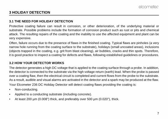
3 HOLIDAY DETECTION
3.1 THE NEED FOR HOLIDAY DETECTION
Protective coating failure can result in corrosion, or other deteriorationsubstrate. Possible problems include the formation of corrosion product suattack. The resulting repairs of the coating and the inability to use the affecvery expensive.
Often, failure occurs due to the presence of flaws in the finished coating. Tnarrow hole running from the coating surface to the substrate), holidays (sm(objects trapped in the coating, e.g. grit from blast cleaning), air bubbles, cit is good practice to inspect a coating for defects and flaws, following estab
3.2 HOW YOUR DETECTOR WORKS
The detector generates a high DC voltage that is applied to the coating surfthe detector is connected to the substrate via the high voltage return (earth)over a coating flaw, then the electrical circuit is completed and current flowsAs a result, audible and visual alarms are activated in the detector and a spa
Your Elcometer 236 DC Holiday Detector will detect coating flaws providin
• Non-conducting.
• Applied to a conducting substrate (including concrete).
• At least 200 µm (0.008") thick, and preferably over 500 µm (0.020"), th

e following list of standards and
ove 2 kV for enamel thicker
bove 900 V) test. Set dielectric breakdown ng. Move probe at 0.3 m/s
st: 10 kV, spark at defect is tion
rior to abrasion testing. Test ulated as
(mil)Thickness
236_TMA_0214_00_04 A6L.fm Page 8 Monday, January 19, 2009 2:25 PM
R
8
4 STANDARDS AND TEST METHODS
The Elcometer 236 DC Holiday Detector can be used in accordance with thtest methods:
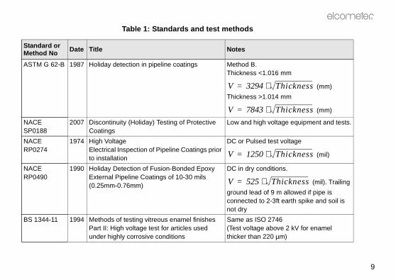
Table 1: Standards and test methods
Standard or Method No Date Title Notes
ISO 2746 1994 Vitreous and porcelain enamels - Enamelled articles for service under highly corrosive conditions - High voltage test
Test voltage abthan 220 µm
ASTM D 4787 1988 Continuity verification of liquid or sheet linings applied to concrete
High voltage (avoltage below strength of lini(1 ft/s) max.
ASTM F 423 1975 PTFE plastic-lined ferrous metal pipe and fittings
Electrostatic tecause for rejec
ASTM G 6 1983 Abrasion resistance of pipeline coatings Porosity test pvoltage is calc
V 1250⋅=
R
9
016 mm
(mm)
014 mm
(mm)
oltage equipment and tests.
test voltage
(mil)
itions.
(mil). Trailing
9 m allowed if pipe is -3ft earth spike and soil is
2746bove 2 kV for enamel 0 µm)
Thickness
Thickness
Thickness
Thickness
236_TMA_0214_00_04 A6L.fm Page 9 Monday, January 19, 2009 2:25 PM
ASTM G 62-B 1987 Holiday detection in pipeline coatings Method B.Thickness <1.
Thickness >1.
NACE SP0188
2007 Discontinuity (Holiday) Testing of Protective Coatings
Low and high v
NACE RP0274
1974 High Voltage Electrical Inspection of Pipeline Coatings prior to installation
DC or Pulsed
NACE RP0490
1990 Holiday Detection of Fusion-Bonded Epoxy External Pipeline Coatings of 10-30 mils (0.25mm-0.76mm)
DC in dry cond
ground lead ofconnected to 2not dry
BS 1344-11 1994 Methods of testing vitreous enamel finishes Part II: High voltage test for articles used under highly corrosive conditions
Same as ISO (Test voltage athicker than 22
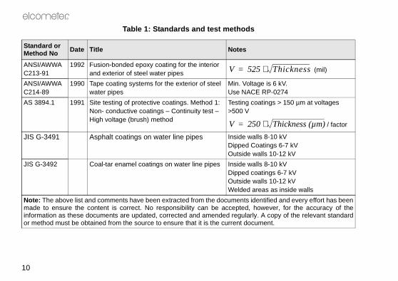
Table 1: Standards and test methods
Standard or Method No Date Title Notes
V 3294⋅=
V 7843⋅=
V 1250⋅=
V 525⋅=
(mil)
6 kV.-0274
s > 150 µm at voltages
/ factor
10 kVgs 6-7 kV10-12 kV
10 kVs 6-7 kV
10-12 kVas inside walls
ed and every effort has beenver, for the accuracy of theopy of the relevant standardt.
Thickness
Thickness (µm)
236_TMA_0214_00_04 A6L.fm Page 10 Monday, January 19, 2009 2:25 PM
R
10
ANSI/AWWAC213-91
1992 Fusion-bonded epoxy coating for the interior and exterior of steel water pipes
ANSI/AWWAC214-89
1990 Tape coating systems for the exterior of steel water pipes
Min. Voltage isUse NACE RP
AS 3894.1 1991 Site testing of protective coatings. Method 1: Non- conductive coatings – Continuity test – High voltage (brush) method
Testing coating>500 V
JIS G-3491 Asphalt coatings on water line pipes Inside walls 8-Dipped CoatinOutside walls
JIS G-3492 Coal-tar enamel coatings on water line pipes Inside walls 8-Dipped coatingOutside walls Welded areas
Note: The above list and comments have been extracted from the documents identifimade to ensure the content is correct. No responsibility can be accepted, howeinformation as these documents are updated, corrected and amended regularly. A cor method must be obtained from the source to ensure that it is the current documen
Table 1: Standards and test methods
Standard or Method No Date Title Notes
V 525⋅=
V 250⋅=
R
11
236_TMA_0214_00_04 A6L.fm Page 11 Monday, January 19, 2009 2:25 PM
5 GETTING STARTED
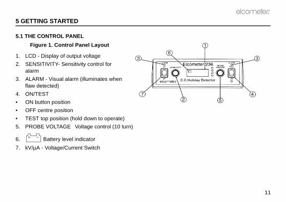
5.1 THE CONTROL PANEL
Figure 1. Control Panel Layout
1. LCD - Display of output voltage
2. SENSITIVITY- Sensitivity control for alarm
3. ALARM - Visual alarm (illuminates when flaw detected)
4. ON/TEST
• ON button position
• OFF centre position
• TEST top position (hold down to operate)
5. PROBE VOLTAGE Voltage control (10 turn)
6. Battery level indicator
7. kV/µA - Voltage/Current Switch
t
4
236_TMA_0214_00_04 A6L.fm Page 12 Monday, January 19, 2009 2:25 PM
R
12
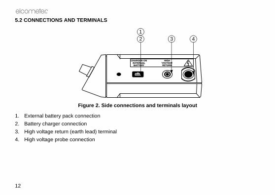
5.2 CONNECTIONS AND TERMINALS
Figure 2. Side connections and terminals layou
1. External battery pack connection
2. Battery charger connection
3. High voltage return (earth lead) terminal
4. High voltage probe connection
12 3
R
13
236_TMA_0214_00_04 A6L.fm Page 13 Monday, January 19, 2009 2:25 PM
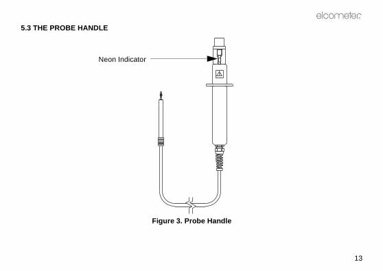
5.3 THE PROBE HANDLE
Figure 3. Probe Handle
Neon Indicator

e as appropriate. The carry caseto a job.
strip. The probe handle or otherro strips provided. The accessorynector that is inserted and twisted
rgeable battery as appropriate. Innside the case outer flap to secureg the detector.. In the event that the strap is lost
long term storage.
236_TMA_0214_00_04 A6L.fm Page 14 Monday, January 19, 2009 2:25 PM
R
14
5.4 THE CARRY CASE
The detector can be used in the carry case or removed from the case for uscan also be used to store and protect the detector when it is being carried
The carry case has an inner flap that can be held open by means of a Velcro™accessories can be attached to the front of the case by means of the two Velcpouch can be locked on to the side of the case by means of the special T type conthrough 90° to lock it in place.The accessory pouch can be used to carry the battery charger or the extra rechause, the lead from the spare battery to the detector is passed through the loops iit. This prevents it hanging loose and catching on any item as the user is carryinThe carry case has a convenient and adjustable shoulder strap for ease of useor damaged a replacement is available - see “Spares” on page 37.The kit is supplied in an outfit case that is also convenient for transportation and

R
15
t.
236_TMA_0214_00_04 A6L.fm Page 15 Monday, January 19, 2009 2:25 PM
5.5 QUICK START GUIDE
ALWAYS read “Working safely” on page 5 before using this equipmen

t.
ut to zero.
low indicator is not shownes charging - see “Charging the
high voltage return (earth) leadf the high voltage return (earth)
nti-clockwise to ensure that the
probe connection and the black
, and attach it to the high voltage
236_TMA_0214_00_04 A6L.fm Page 16 Monday, January 19, 2009 2:25 PM
R
16
6 USING THE HOLIDAY DETECTOR
ALWAYS read “Working safely” on page 5 before using this equipmen
6.1 TEST BATTERIES
Turn PROBE VOLTAGE control fully anti-clockwise to set the voltage outp
Push and hold down ON/TEST switch to the TEST position. If the battery on the display the instrument is ready for use. Otherwise the battery requirbattery” on page 35.
6.2 CONNECT LEADS
Note: If the detector is being used in the carry case provided, slip the through the loop on the side of the case. This will reduce the possibility olead becoming detached accidentally.
Switch ON/TEST to the centre position and turn PROBE VOLTAGE fully ainstrument is safe (minimum output voltage).
Connect the black high voltage probe handle and lead to the high voltage high voltage return (earth) lead to the High voltage return terminal.
6.3 SELECT PROBE
Select the probe best suited for the work (see “Probe selection” on page 28)probe.

R
17
urpose of this test method onlye range selection switch should
marked ON to turn the detector
t of 1 kV and turn SENSITIVITY
ction.
ator in the probe handle should
SITIVITY fully anti-clockwise to
ction is not satisfactory. Repeatstill not satisfactory, refer to conductor and the coating an
236_TMA_0214_00_04 A6L.fm Page 17 Monday, January 19, 2009 2:25 PM
6.4 CONNECT HIGH VOLTAGE RETURN TO SUBSTRATE
Clamp the high voltage return cable (earth lead) to exposed substrate.
6.5 CHECK OPERATION OF HIGH VOLTAGE RETURN CONNECTI ON
The instrument has two measurement ranges voltage or current. For the pthe voltage range is of interest. To select the voltage measurement range thbe in the kV position.
Holding the probe by its handle and in free air, press ON/TEST on the sideon.
Turn PROBE VOLTAGE clockwise until the LCD display indicates an outpufully clockwise.
Place the probe on bare substrate or the high voltage return (earth) conne
The audible alarm should sound, ALARM should light and the neon indicglow, indicating that the high voltage return connection is good.
Switch ON/TEST to the centre position. Turn PROBE VOLTAGE and SENleave the detector in a safe condition.
If the detector does not respond as described then the high voltage conneall the previous steps and try again. If the high voltage return is “Troubleshooting” on page 30. In addition, confirm that the substrate is ainsulator. If this is not the case, then the detector will not work.
tivity” on page 22.
ed on the LCD display.
e “Setting the test voltage and
ection 6.9, test that the flaw can
ndertaken correctly. If so, then
rface and move it over the work(10"/s).
in the coating:
236_TMA_0214_00_04 A6L.fm Page 18 Monday, January 19, 2009 2:25 PM
R
18
6.6 SET TEST VOLTAGE
For test voltage selection methods, see “Setting the test voltage and sensi
Holding the probe in free air press ON position to turn the detector on.
Turn PROBE VOLTAGE clockwise until the required test voltage is indicat
6.7 SET ALARM SENSITIVITY
Turn SENSITIVITY clockwise to set the sensitivity to a suitable level, sesensitivity” on page 22 for details on setting sensitivity.
6.8 CHECK FOR CORRECT OPERATION
Either find or make a flaw in the coating. Using the procedure outlined in sbe located.
If the flaw is not detected, check that all the preceding steps have been urefer to “Troubleshooting” on page 30.
6.9 INSPECT COATING FOR FLAWS
Place the probe on the test surface. Keep the probe in contact with the suarea at a speed of approximately one metre every four seconds, 0.25 m/s
The presence of one or more of the following indicates that there is a flaw
• A spark between the probe and the surface
• ALARM flashes
• The audible alarm sounds
R
19
he coating can result in genuine
itched off and the output voltage
osition, the connections shouldn” on page 17.
ecting the leads, when work is
up which can:
same polarity.
the surface.
236_TMA_0214_00_04 A6L.fm Page 19 Monday, January 19, 2009 2:25 PM
• The output voltage, indicated on the LCD display, drops substantially
• The probe neon indicator glows
The probe should always touch the surface. Gaps between the probe and tflaws not being detected.
6.10 MOVING WORK POSITION AND FINISHING WORK
Prior to repositioning the high voltage return lead, the detector should be swturned to zero .
When the high voltage return (earth lead) has been attached at its new palways be checked - see “Check operation of high voltage return connectio
Always turn the detector off and set the voltage to zero before disconnfinished and when leaving work unattended.
7 STATIC ELECTRICITY
As the probe is moved over the surface of a coating, a static charge builds
• Cause objects in contact with the surface to become charged with the
• Induce an opposite charge on nearby objects electrically insulated from

if inside a short pipe insulated
e body from becoming charged.side the pipe if an un-insulated
ce should be bonded to a earth isolated test piece for several
236_TMA_0214_00_04 A6L.fm Page 20 Monday, January 19, 2009 2:25 PM
R
20
The following examples demonstrate the possible effects on the operatorfrom the ground:
AVOIDING STATIC SHOCK
A conductive strap between the operator and the ground (earth) will stop thRubber gloves and footwear should be worn. There may still be a shock inpart of the body touches the charged coating.
In addition to the above methods it is also recommended that the work piepotential thus preventing any build-up of charge, which can remain on aminutes after testing has been completed.
Operator not wearing rubbergloves or footwear:
Operator wearing rubber gloves and footwear:
The operator is touching the coating. The rubber gloves and footwear insulate them from the coating.
The body then becomes charged at the same polarity as the coating.
The body becomes charged with the opposite polarity to the coating
No shock if the coating is touched. If an uninsulated part of the Operator touches the coating, discharge will cause a shock.
The operator gets a shock stepping from the pipe to the ground.
The operator gets a shock stepping from the pipe to the ground
R
21
ltage probe, the instrument is alsoe work piece and back to the highed on partially conductive coatingshe breakdown voltage of insulation
be connected to the substrate orand applied to the coating surface the electrical circuit is closed. Thisay be produced between the probe
conductive coating.ge of the insulating material. Thusproximate insulation resistance of
for this reason the alarm is set to
t be changed, this is achieved by
236_TMA_0214_00_04 A6L.fm Page 21 Monday, January 19, 2009 2:25 PM
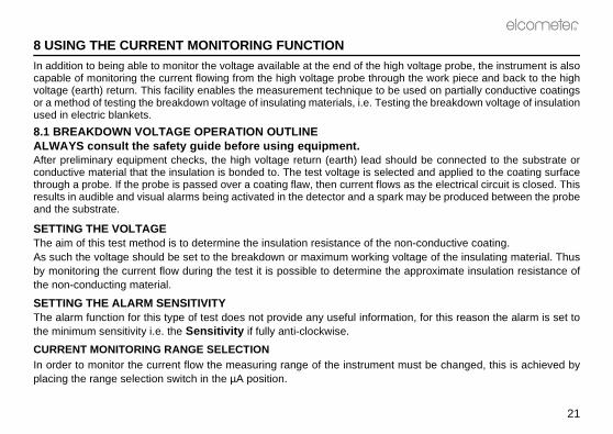
8 USING THE CURRENT MONITORING FUNCTION
In addition to being able to monitor the voltage available at the end of the high vocapable of monitoring the current flowing from the high voltage probe through thvoltage (earth) return. This facility enables the measurement technique to be usor a method of testing the breakdown voltage of insulating materials, i.e. Testing tused in electric blankets.
8.1 BREAKDOWN VOLTAGE OPERATION OUTLINEALWAYS consult the safety guide before using equipm ent.After preliminary equipment checks, the high voltage return (earth) lead shouldconductive material that the insulation is bonded to. The test voltage is selected through a probe. If the probe is passed over a coating flaw, then current flows asresults in audible and visual alarms being activated in the detector and a spark mand the substrate.
SETTING THE VOLTAGEThe aim of this test method is to determine the insulation resistance of the non-As such the voltage should be set to the breakdown or maximum working voltaby monitoring the current flow during the test it is possible to determine the apthe non-conducting material.
SETTING THE ALARM SENSITIVITYThe alarm function for this type of test does not provide any useful information,the minimum sensitivity i.e. the Sensitivity if fully anti-clockwise.
CURRENT MONITORING RANGE SELECTIONIn order to monitor the current flow the measuring range of the instrument musplacing the range selection switch in the µA position.

limits. The upper voltage limit isfore, the test voltage should ben the thickness of air equivalent then a flaw will not be detected.
s may be determined.
ctricity. However, for insulators, results in irreversible material
ed the dielectric strength. This depends on the type of appliedhows the relationship betweentrengths.
by its thickness and the lower
f 10 kV/mm to 30 kV/mm. The
236_TMA_0214_00_04 A6L.fm Page 22 Monday, January 19, 2009 2:25 PM
R
22
9 SETTING THE TEST VOLTAGE AND SENSITIVITY
For effective testing, the output voltage must lie between upper and lower that at which the coating itself would breakdown and be damaged. Therelower than this value. The lower limit is the voltage required to break dowto the coating thickness. If the output voltage is not greater than this value,
The following describes how the band of safe, but effective, voltage output
9.1 DIELECTRIC STRENGTH
Whatever the material, if a high enough voltage is applied, it will conduct elee.g. paint, the level of voltage required to achieve a current flow usuallydamage.
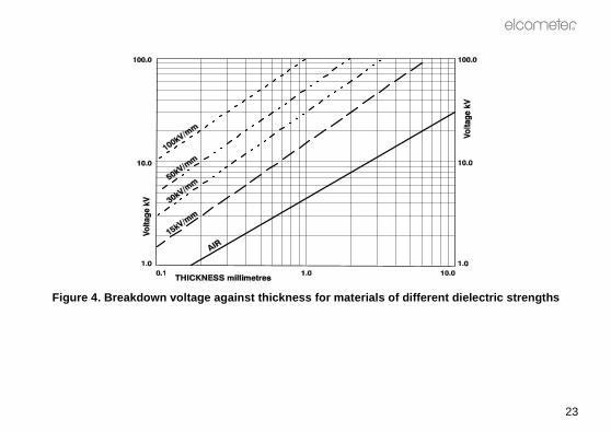
The voltage at which a particular thickness of material breaks down is termis usually expressed as the voltage per unit distance, e.g. kV/mm. Its valuevoltage, e.g. AC, DC or pulsed, temperature and thickness. Figure 4 sbreakdown voltage (DC) and thickness for materials of different dielectric s
The upper voltage limit is the dielectric strength of the material multipliedvoltage limit is the dielectric strength of air multiplied by the thickness.
The dielectric strength of coating materials usually lies in the region odielectric strength of air ranges from 1.3 kV/mm to 4 kV/mm.
R
23
erent dielectric strengths
236_TMA_0214_00_04 A6L.fm Page 23 Monday, January 19, 2009 2:25 PM
Figure 4. Breakdown voltage against thickness for m aterials of diff
ickness of air equivalent to theies with humidity, pressure and
can be read from Figure 4, usingthe lower limit is ~ 4.5 kV.
stablished experimentally. Turnof substrate at the normal height produced and note the voltage.
alculate the maximum voltage,uivalent to 25.4 V per mil (thou).
termined for a DC voltage.
Increase the voltage slowly and The dielectric strength can be
236_TMA_0214_00_04 A6L.fm Page 24 Monday, January 19, 2009 2:25 PM
R
24
9.2 ESTABLISHING THE VOLTAGE LIMITS
THE LOWER LIMIT
The lower limit for effective operation is that required to breakdown the thcoating thickness. The breakdown voltage of a given thickness of air vartemperature but is ~ 4 kV/mm (0.1 kV/mil)
If the coating thickness is known, or can be measured, the lower limit value the line marked AIR. For instance, if the coating thickness is 1.0 mm then
If the coating thickness is not known then the minimum value has to be ethe output voltage to zero and position the probe over an unprotected area of the coating surface. Turn the voltage up slowly and steadily until a spark isThis voltage forms the lower limit.
THE UPPER LIMIT
The upper voltage limit may be determined by:
The job specification - if available and a test voltage is stated.
The dielectric strength - if specified for the applied coating.
Measure the thickness of the layer and refer to Figure 4. Alternatively, callowing for variations in the coating thickness. Note that 1 kV per mm is eq
Note: This method is only suitable if the dielectric strength values were de
Experiment - Touch the probe on an unimportant area of the work piece. steadily until a spark passes through the coating and note the voltage.calculated by dividing this voltage by the coating thickness.
R
25
roximately halfway between the
ggers when a flaw is detected. It the coating or moist air, can be
d and makes the detector morector sensitivity and the lowestum detector sensitivity and the
e absence of a fault, e.g. due to
236_TMA_0214_00_04 A6L.fm Page 25 Monday, January 19, 2009 2:25 PM
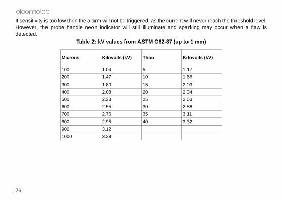
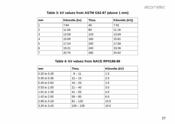
Tables and formulae - from established Codes of Practice,
e.g. NACE and ASTM. See Table 2, Table 3 and Table 4.
9.3 SETTING THE TEST VOLTAGE
Once the voltage limits have been established, set the output voltage apptwo values.
9.4 SETTING ALARM SENSITIVITY
Alarm sensitivity is the current threshold or level, above which the alarm triis adjustable so that the effects of any prevailing electrical leakage, throughcounteracted to prevent false alarms.
Turning the SENSITIVITY knob clockwise, decreases the current thresholsensitive. SENSITIVITY turned fully clockwise gives the maximum detethreshold current SENSITIVITY turned fully anti-clockwise gives the minimhighest threshold current.
If the sensitivity is too high, the alarm will operate when current flows in thdamp surfaces or slightly conductive coatings.
never reach the threshold level.ing may occur when a flaw is
m)
lts (kV)
236_TMA_0214_00_04 A6L.fm Page 26 Monday, January 19, 2009 2:25 PM
R
26
If sensitivity is too low then the alarm will not be triggered, as the current willHowever, the probe handle neon indicator will still illuminate and sparkdetected.
Table 2: kV values from ASTM G62-87 (up to 1 m
Microns Kilovolts (kV) Thou Kilovo
100 1.04 5 1.17
200 1.47 10 1.66
300 1.80 15 2.03
400 2.08 20 2.34
500 2.33 25 2.63
600 2.55 30 2.88
700 2.76 35 3.11
800 2.95 40 3.32
900 3.12
1000 3.29
R
27
mm)
lts (kV))
8
9
1
8
6
2
V)
236_TMA_0214_00_04 A6L.fm Page 27 Monday, January 19, 2009 2:25 PM
Table 3: kV values from ASTM G62-87 (above 1
mm Kilovolts (kv) Thou Kilovo
1 7.84 40 7.91
2 11.09 80 11.1
3 13.58 120 13.6
4 15.69 160 15.8
5 17.54 200 17.6
6 19.21 240 19.3
7 20.75 280 20.9
Table 4: kV values from NACE RP0188-88
mm Thou Kilovolts (k
0.20 to 0.28 18 – 11 1.5
0.30 to 0.38 12 – 15 2.0
0.40 to 0.50 16 – 20 2.5
0.53 to 1.00 21 – 40 3.0
1.01 to 1.39 41 – 55 4.0
1.42 to 2.00 56 – 80 6.0
2.06 to 3.18 81 – 125 10.0
3.20 to 3.43 126 – 135 15.0

stics of the surface to be tested,hapes. In addition, long reachr use with all probe types. Theoining the extension pieces with
le from Elcometer or your localed with this detector.
bers, are given in “Spares” on
s
w contact
n different h conductive ht contact and ronze wire contact
236_TMA_0214_00_04 A6L.fm Page 28 Monday, January 19, 2009 2:25 PM
R
28
10 PROBE SELECTION
Table 5 shows the most suitable probe to use depending on the characterie.g. internal and external pipe surfaces, large surfaces and complex sapplications can be carried out using extension pieces that are suitable foextension pieces are available in 250 mm, 500 mm and 1000 mm lengths. Ja coupling can make up other lengths.
All probes, extensions and couplings mentioned in this Section are availabElcometer supplier. Only those fittings supplied by Elcometer should be us
Further details of the probes and other accessories, including part numpage 37.
Table 5: The best probe for various surface type
Type of Surface Recommended Probe Notes
Small area, complex surface, general application
Band brush probe Provides lopressure
Large surface areas Right-angle brush probe Available iwidths, witstrip for ligphosphor bfor medium

R
29
50 mm rod
r bronze a 250 mm rod supplied d
s
236_TMA_0214_00_04 A6L.fm Page 29 Monday, January 19, 2009 2:25 PM
Insides of pipes 40 mm to 300 mm (1.5” to 12") diameter
Circular brush probe Includes 2extension
Outside of pipes, 50 mm to 1000 mm (2” to 36") diameter
Rolling spring probe A phosphospring withextension as standar
Table 5: The best probe for various surface type
Type of Surface Recommended Probe Notes
section 12.1
e or use a larger capacity
aller probe (see section 10) ge
section 6.2
236_TMA_0214_00_04 A6L.fm Page 30 Monday, January 19, 2009 2:25 PM
R
30
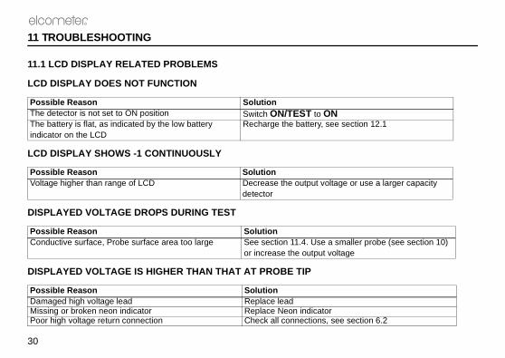
11 TROUBLESHOOTING
11.1 LCD DISPLAY RELATED PROBLEMS
LCD DISPLAY DOES NOT FUNCTION
LCD DISPLAY SHOWS -1 CONTINUOUSLY
DISPLAYED VOLTAGE DROPS DURING TEST
DISPLAYED VOLTAGE IS HIGHER THAN THAT AT PROBE TIP
Possible Reason SolutionThe detector is not set to ON position Switch ON/TEST to ON The battery is flat, as indicated by the low battery indicator on the LCD
Recharge the battery, see
Possible Reason SolutionVoltage higher than range of LCD Decrease the output voltag
detector
Possible Reason SolutionConductive surface, Probe surface area too large See section 11.4. Use a sm
or increase the output volta
Possible Reason SolutionDamaged high voltage lead Replace leadMissing or broken neon indicator Replace Neon indicatorPoor high voltage return connection Check all connections, see
R
31
on page 32g SENSITIVITY anti-
tion 10
ing SENSITIVITY
PROBE VOLTAGE 9
aged
onnect leads, see section 6.2ion 12.1
236_TMA_0214_00_04 A6L.fm Page 31 Monday, January 19, 2009 2:25 PM
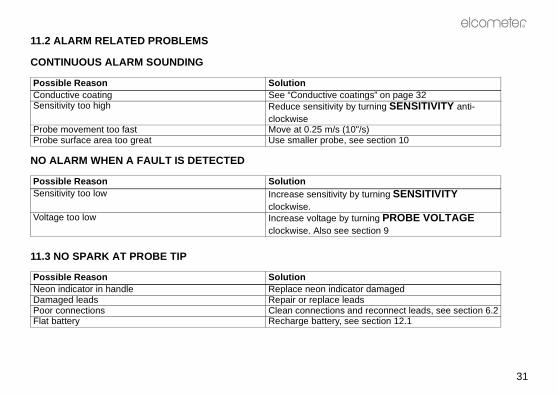
11.2 ALARM RELATED PROBLEMS
CONTINUOUS ALARM SOUNDING
NO ALARM WHEN A FAULT IS DETECTED
11.3 NO SPARK AT PROBE TIP
Possible Reason SolutionConductive coating See “Conductive coatings”Sensitivity too high Reduce sensitivity by turnin
clockwiseProbe movement too fast Move at 0.25 m/s (10"/s)Probe surface area too great Use smaller probe, see sec
Possible Reason SolutionSensitivity too low Increase sensitivity by turn
clockwise.Voltage too low Increase voltage by turning
clockwise. Also see section
Possible Reason SolutionNeon indicator in handle Replace neon indicator damDamaged leads Repair or replace leadsPoor connections Clean connections and recFlat battery Recharge battery, see sect

pplied to the test surface or thesual occurrences of conductive
OATING: During normal use, thes subjected to high voltages theg becoming conductive and the
enough to detect flaws but lowating will still conduct at voltagesuitable method for checking the
re from the atmosphere and thisce to the high voltage that is noton-existent flaws. When thesee cloth or cleaned with a non-
test area before re-commencing
. glass reinforced plastic alongimmersed in water. In this case,
236_TMA_0214_00_04 A6L.fm Page 32 Monday, January 19, 2009 2:25 PM
R
32
11.4 SPECIAL CONSIDERATIONS
CONDUCTIVE COATINGS
As stated above, if the displayed voltage drops sharply when the probe is aalarm sounds continuously, then the coating may be conductive. The ucoatings are described in the following.
EXISTENCE OF METALLIC, CARBON OR OTHER CONDUCTING PARTICLES IN THE Cparticles in this type of coating are not linked. However, when the coating imaterial between the particles can break down. This results in the coatindetector indicating the presence of a flaw.
To overcome this effect, the voltage should be reduced so that it is still highenough to avoid break down of the coating. However, in some cases the cothat are too low to locate a flaw. In this case, the holiday detector is not a scoating.
SURFACE MOISTURE OR CONTAMINATION: Certain soluble salts attract moistuand other forms of surface contamination can form a path across the surfadue to a coating flaw. Under these conditions the detector indicates ncircumstances occur, the surface should either be dried using a suitablconducting cleaner or solvent which will not damage the coating.
Note: Ensure that any cleaner or solvent containers are removed from the the test.
MOISTURE PENETRATION OR ABSORPTION: Moisture can enter materials, e.gthe reinforcing glass fibres, if the surface is eroded or scratched and then allow adequate time for the coating to dry prior to testing.
R
33
ntent. As with other conductiven flaw but does not sound when the test voltage to compensate
vents which allow the path to theoblem, allow the coating to cure
nduct electricity and the holiday
y Detector” on page 16, but theducting spike, into the concrete
ked using the following. Make a. Attach the high voltage returnge 3 kV - 6 kV if the test voltage
il. If the alarm sounds, then the
at the holiday detector will be a
236_TMA_0214_00_04 A6L.fm Page 33 Monday, January 19, 2009 2:25 PM
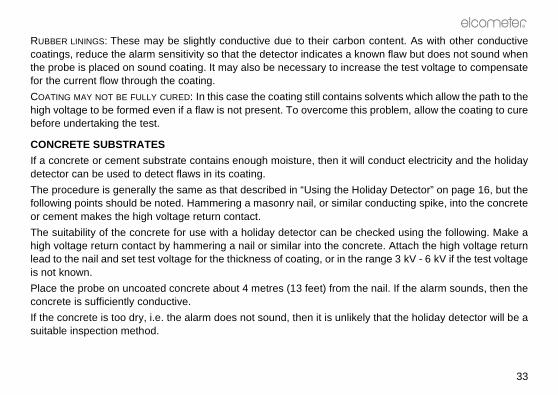
RUBBER LININGS: These may be slightly conductive due to their carbon cocoatings, reduce the alarm sensitivity so that the detector indicates a knowthe probe is placed on sound coating. It may also be necessary to increasefor the current flow through the coating.
COATING MAY NOT BE FULLY CURED: In this case the coating still contains solhigh voltage to be formed even if a flaw is not present. To overcome this prbefore undertaking the test.
CONCRETE SUBSTRATES
If a concrete or cement substrate contains enough moisture, then it will codetector can be used to detect flaws in its coating.
The procedure is generally the same as that described in “Using the Holidafollowing points should be noted. Hammering a masonry nail, or similar conor cement makes the high voltage return contact.
The suitability of the concrete for use with a holiday detector can be chechigh voltage return contact by hammering a nail or similar into the concretelead to the nail and set test voltage for the thickness of coating, or in the ranis not known.
Place the probe on uncoated concrete about 4 metres (13 feet) from the naconcrete is sufficiently conductive.
If the concrete is too dry, i.e. the alarm does not sound, then it is unlikely thsuitable inspection method.
hen a longer high voltage return
operator and that the voltage
s specified by the manufacturerngth (10 m) may lead to the unitiece is being inspected a similarter Supplier.
r normal operating and storage
able components. In the unlikelyr Supplier. The warranty will be
of these Operating Instructions.
nsisting of a nickel metal hydride
236_TMA_0214_00_04 A6L.fm Page 34 Monday, January 19, 2009 2:25 PM
R
34
LENGTHENING THE HIGH VOLTAGE RETURN (EARTH) LEAD
If the high voltage return connection is at some distance from the test area tlead should be used- see “Other accessories” on page 44.
This ensures that the detector, and therefore alarms, will be close to thedecrease in the probe lead will be not be too high.
Note: In order to comply with the EMC directive only earth return lead lengthshould be utilised. Increasing the length of the lead beyond the maximum lebeing susceptible to radio frequency interference. Likewise if a large test peffect may be observed. If in doubt consult Elcometer or your local Elcome
12 MAINTENANCE
Your Holiday Detector is designed to give many years reliable service undeconditions.
The Elcometer 236 DC Holiday Detector does not contain any user-serviceevent of a fault, return your Detector to Elcometer or your local Elcometeinvalidated if the instrument has been opened.
Details of Elcometer offices around the world are given on the outside coverAlternatively visit the Elcometer website, www.elcometer.com
12.1 BATTERY MAINTENANCE
The Elcometer 236 is designed to operate from an internal power source cobattery. As such, there is no battery maintenance required.
R
35
uncharged state and must be
ing on the working voltage and life is greater than 20 hours. be attempted with the charger
attery. This will give continuousn page 44 for ordering details.
lights on the display. Once this before the performance of the
he charger supplied. When thee turned off and if an externaln recharged.
trument or external battery pack battery is charging correctly. In
l Elcometer Supplier for repair.
the charger unit will flash on a
236_TMA_0214_00_04 A6L.fm Page 35 Monday, January 19, 2009 2:25 PM
For safety and reliability, the battery is dispatched from Elcometer in ancharged before use.
The battery life for the 30 kV unit is typically greater than 10 hours dependnumber of faults found during the working day. The 15 kV unit batteryRecharging the battery will take approximately 12 hours and should onlysupplied with the instrument.
An external battery can be connected to the unit, bypassing the internal boperation exceeding 10 or 20 hours if required - see “Other accessories” o
CHARGING THE BATTERY
Charging of the battery is not required until the battery low level symbol symbol shows, there should be approximately half an hour of battery lifeinstrument will suffer.
Charging of internal or external batteries should only be attempted with tbattery low indicator shows in the display, the instrument should bbattery is being used this should be unplugged from the instrument and the
The charger should then be plugged into the appropriate socket on the insand the mains power switched on. A red light on the charger shows that thethe event that the light does not come on, return to Elcometer or your loca
After 12 hours the battery will be fully charged, at this time the red light onregular basis.

t whilst the battery is charging, the instrument itself.
for damage at regular intervals.s” on page 37 for replacement
onitors are all in working ordere section 12.1).
ificate of Calibration is required,and certification. Renewal of the
Crystal Display. If the display isn if the conductivity meter is left
y Detector in the carrying case
236_TMA_0214_00_04 A6L.fm Page 36 Monday, January 19, 2009 2:25 PM
R
36
WARNING: No attempt should be made to use the instrumendoing so may result in permanent damage to the charger and or
12.2 ROUTINE CHECKS
Check the detector, probe and high voltage return leads and connectors Replace any parts that are worn or are of doubtful condition. See “Spareparts.
If the detector is not being used regularly, check that the indicators and m(See section 6.1 to section 6.5) and recharge the battery as necessary (Se
Certificates of Calibration can be issued at the time of purchase. If a Certreturn the detector to Elcometer or your local Elcometer Supplier, for retest Certificate is recommended on an annual basis.
13 STORAGE
The Elcometer 236 DC Holiday Detector incorporates a Liquid heated above 50°C (120°F) it may be damaged. This c an happein a car parked in strong sunlight.
Always store the components of the Elcometer 236 DC Holidawhen the Detector is not being used.
R
37
. They are available in 3 widths
sion pieces can be added using
or ip
236_TMA_0214_00_04 A6L.fm Page 37 Monday, January 19, 2009 2:25 PM
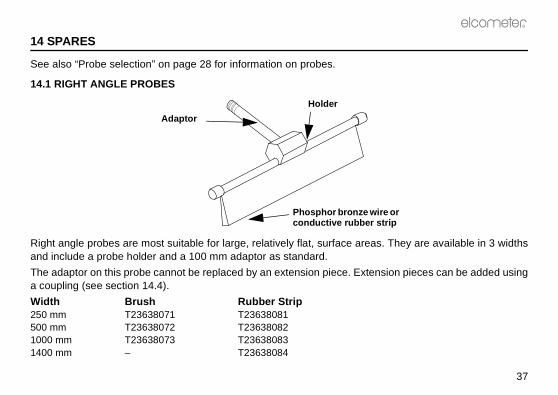
14 SPARES
See also “Probe selection” on page 28 for information on probes.
14.1 RIGHT ANGLE PROBES
Right angle probes are most suitable for large, relatively flat, surface areasand include a probe holder and a 100 mm adaptor as standard.
The adaptor on this probe cannot be replaced by an extension piece. Extena coupling (see section 14.4).
Width Brush Rubber Strip250 mm T23638071 T23638081500 mm T23638072 T236380821000 mm T23638073 T236380831400 mm – T23638084
Adaptor
Holder
Phosphor bronze wireconductive rubber str
A
Adaptor T2363901
Extension piece T2362663A
236_TMA_0214_00_04 A6L.fm Page 38 Monday, January 19, 2009 2:25 PM
R
38
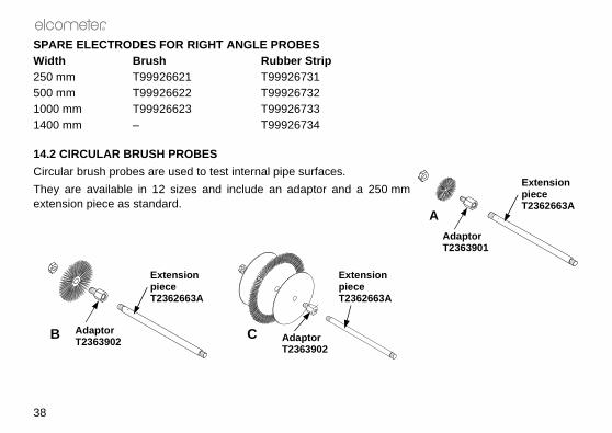
SPARE ELECTRODES FOR RIGHT ANGLE PROBESWidth Brush Rubber Strip250 mm T99926621 T99926731500 mm T99926622 T999267321000 mm T99926623 T999267331400 mm – T99926734
14.2 CIRCULAR BRUSH PROBES
Circular brush probes are used to test internal pipe surfaces.
They are available in 12 sizes and include an adaptor and a 250 mmextension piece as standard.
B CAdaptor T2363902
Extension piece T2362663A
Adaptor T2363902
Extension piece T2362663A
R
39
236_TMA_0214_00_04 A6L.fm Page 39 Monday, January 19, 2009 2:25 PM
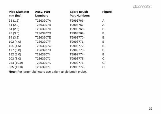
Pipe Diameter Assy. Part Spare Brush Figuremm (ins) Numbers Part Numbers
38 (1.5) T2363907A T9993766- A51 (2.0) T2363907B T9993767- A64 (2.5) T2363907C T9993768- B76 (3.0) T2363907D T9993769- B89 (3.5) T2363907E T9993770- B102 (4.0) T2363907F T9993771- B114 (4.5) T2363907G T9993772- B127 (5.0) T2363907H T9993773- B152 (6.0) T2363907I T9993774- B203 (8.0) T2363907J T9993775- C254 (10.0) T2363907K T9993776- C305 (12.0) T2363907L T9993777- C
Note: For larger diameters use a right angle brush probe.
236_TMA_0214_00_04 A6L.fm Page 40 Monday, January 19, 2009 2:25 PM
R
40
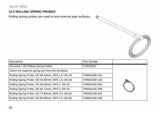
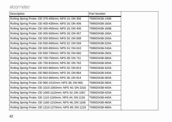
14.3 ROLLING SPRING PROBES
Rolling spring probes are used to test external pipe surfaces.
Description Part Number
Elcometer 236 Rolling Spring Holder T23620507
Select the required spring size from the list below
Rolling Spring Probe: OD 48-54mm; NPS 1.5; DN 40 T99920438-15A
Rolling Spring Probe: OD 54-60mm; NPS 1.5; DN 40 T99920438-15B
Rolling Spring Probe: OD 60-65mm; NPS 2; DN 50 T99920438-20A
Rolling Spring Probe: OD 66-73mm; NPS 2; DN 50 T99920438-20B
Rolling Spring Probe: OD 73-80mm; NPS 2.5; DN 65 T99920438-25A
Rolling Spring Probe: OD 80-88mm; NPS 2.5; DN 65 T99920438-25B
R
41
236_TMA_0214_00_04 A6L.fm Page 41 Monday, January 19, 2009 2:25 PM
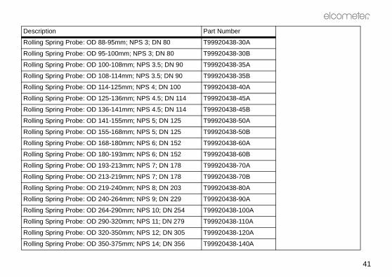
Rolling Spring Probe: OD 88-95mm; NPS 3; DN 80 T99920438-30A
Rolling Spring Probe: OD 95-100mm; NPS 3; DN 80 T99920438-30B
Rolling Spring Probe: OD 100-108mm; NPS 3.5; DN 90 T99920438-35A
Rolling Spring Probe: OD 108-114mm; NPS 3.5; DN 90 T99920438-35B
Rolling Spring Probe: OD 114-125mm; NPS 4; DN 100 T99920438-40A
Rolling Spring Probe: OD 125-136mm; NPS 4.5; DN 114 T99920438-45A
Rolling Spring Probe: OD 136-141mm; NPS 4.5; DN 114 T99920438-45B
Rolling Spring Probe: OD 141-155mm; NPS 5; DN 125 T99920438-50A
Rolling Spring Probe: OD 155-168mm; NPS 5; DN 125 T99920438-50B
Rolling Spring Probe: OD 168-180mm; NPS 6; DN 152 T99920438-60A
Rolling Spring Probe: OD 180-193mm; NPS 6; DN 152 T99920438-60B
Rolling Spring Probe: OD 193-213mm; NPS 7; DN 178 T99920438-70A
Rolling Spring Probe: OD 213-219mm; NPS 7; DN 178 T99920438-70B
Rolling Spring Probe: OD 219-240mm; NPS 8; DN 203 T99920438-80A
Rolling Spring Probe: OD 240-264mm; NPS 9; DN 229 T99920438-90A
Rolling Spring Probe: OD 264-290mm; NPS 10; DN 254 T99920438-100A
Rolling Spring Probe: OD 290-320mm; NPS 11; DN 279 T99920438-110A
Rolling Spring Probe: OD 320-350mm; NPS 12; DN 305 T99920438-120A
Rolling Spring Probe: OD 350-375mm; NPS 14; DN 356 T99920438-140A
Description Part Number
236_TMA_0214_00_04 A6L.fm Page 42 Monday, January 19, 2009 2:25 PM
R
42
Rolling Spring Probe: OD 375-400mm; NPS 14; DN 356 T99920438-140B
Rolling Spring Probe: OD 400-435mm; NPS 16; DN 406 T99920438-160A
Rolling Spring Probe: OD 435-450mm; NPS 16; DN 406 T99920438-160B
Rolling Spring Probe: OD 450-500mm; NPS 18; DN 457 T99920438-180A
Rolling Spring Probe: OD 500-550mm; NPS 20; DN 508 T99920438-200A
Rolling Spring Probe: OD 550-600mm; NPS 22; DN 559 T99920438-220A
Rolling Spring Probe: OD 600-650mm; NPS 24; DN 610 T99920438-240A
Rolling Spring Probe: OD 650-700mm; NPS 26; DN 660 T99920438-260A
Rolling Spring Probe: OD 700-750mm; NPS 28; DN 711 T99920438-280A
Rolling Spring Probe: OD 750-810mm; NPS 30; DN 762 T99920438-300A
Rolling Spring Probe: OD 810-860mm; NPS 32; DN 813 T99920438-320A
Rolling Spring Probe: OD 860-910mm; NPS 34; DN 864 T99920438-340A
Rolling Spring Probe: OD 910-960mm; NPS 36; DN 914 T99920438-360A
Rolling Spring Probe: OD 960-1010mm; NPS 38; DN 965 T99920438-380A
Rolling Spring Probe: OD 1010-1060mm; NPS 40; DN 1016 T99920438-400A
Rolling Spring Probe: OD 1060-1110mm; NPS 42; DN 1067 T99920438-420A
Rolling Spring Probe: OD 1110-1160mm; NPS 44; DN 1118 T99920438-440A
Rolling Spring Probe: OD 1160-1210mm; NPS 46; DN 1168 T99920438-460A
Rolling Spring Probe: OD 1210-1270mm; NPS 48; DN 1219 T99920438-480A
Description Part Number

R
43
equires a coupling piece.
robes. This probe extends from Number is T23615597
236_TMA_0214_00_04 A6L.fm Page 43 Monday, January 19, 2009 2:25 PM
14.4 EXTENSION PIECES
Extension pieces allow the reach of all probes to be increased. Each one r
Length Part Number
250mm T2362663A500mm T2362663B1000mm T2362663CCoupling Piece T2362666-
An insulated probe extension assembly is also available for use with brush p800 mm to 1250 mm (31.5" to 49") and has 2 m (6' 6") of cable. Sales Part
Rolling Spring Probe: OD 1270-1320mm; NPS 50; DN 1270 T99920438-500A
Rolling Spring Probe: OD 1320-1370mm; NPS 52; DN 1321 T99920438-520A
Rolling Spring Probe: OD 1370-1425mm; NPS 54; DN 1372 T99920438-540A
Description Part Number
236_TMA_0214_00_04 A6L.fm Page 44 Monday, January 19, 2009 2:25 PM
R
44
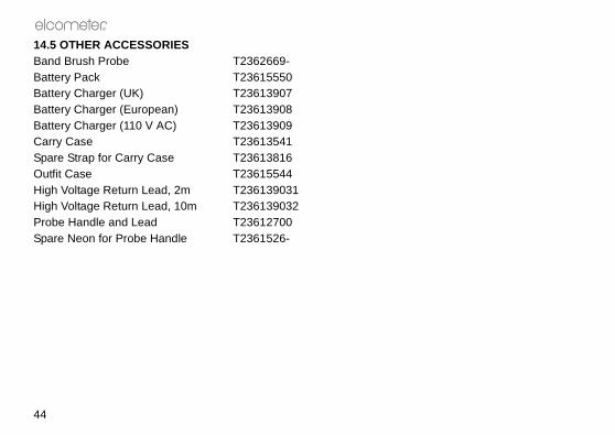
14.5 OTHER ACCESSORIESBand Brush Probe T2362669-Battery Pack T23615550Battery Charger (UK) T23613907Battery Charger (European) T23613908Battery Charger (110 V AC) T23613909Carry Case T23613541Spare Strap for Carry Case T23613816Outfit Case T23615544High Voltage Return Lead, 2m T236139031High Voltage Return Lead, 10m T236139032Probe Handle and Lead T23612700Spare Neon for Probe Handle T2361526-
R
45
lele
ttery (nickel metal hydride type) attery available as accessory.
4 Ah to 5 Ah battery, 12 hours for o plug or US (110 V) plug versions
70mm
e handle
g carry case and band brush
236_TMA_0214_00_04 A6L.fm Page 45 Monday, January 19, 2009 2:25 PM
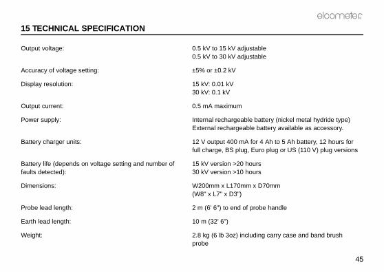
15 TECHNICAL SPECIFICATION
Output voltage: 0.5 kV to 15 kV adjustab0.5 kV to 30 kV adjustab
Accuracy of voltage setting: ±5% or ±0.2 kV
Display resolution: 15 kV: 0.01 kV30 kV: 0.1 kV
Output current: 0.5 mA maximum
Power supply: Internal rechargeable baExternal rechargeable b
Battery charger units: 12 V output 400 mA for full charge, BS plug, Eur
Battery life (depends on voltage setting and number of faults detected):
15 kV version >20 hours30 kV version >10 hours
Dimensions: W200mm x L170mm x D(W8" x L7" x D3")
Probe lead length: 2 m (6' 6") to end of prob
Earth lead length: 10 m (32' 6")
Weight: 2.8 kg (6 lb 3oz) includinprobe
that this packaging is disposedal Authority for further guidance.
a wide range of other equipmentmeter 236 DC Holiday Detector
elcometer.com
front panel.
it height
236_TMA_0214_00_04 A6L.fm Page 46 Monday, January 19, 2009 2:25 PM
R
46
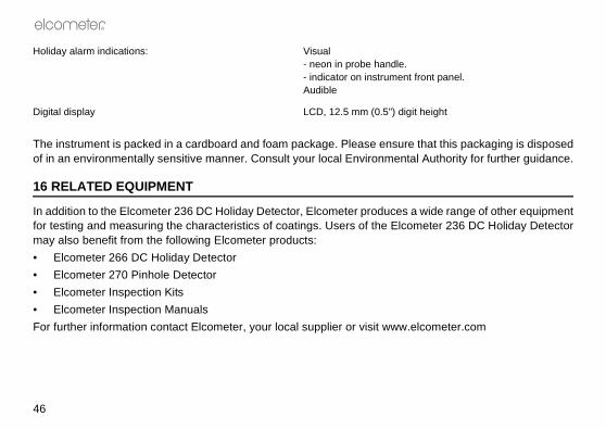
The instrument is packed in a cardboard and foam package. Please ensureof in an environmentally sensitive manner. Consult your local Environment
16 RELATED EQUIPMENT
In addition to the Elcometer 236 DC Holiday Detector, Elcometer produces for testing and measuring the characteristics of coatings. Users of the Elcomay also benefit from the following Elcometer products:
• Elcometer 266 DC Holiday Detector
• Elcometer 270 Pinhole Detector
• Elcometer Inspection Kits
• Elcometer Inspection Manuals
For further information contact Elcometer, your local supplier or visit www.
Holiday alarm indications: Visual- neon in probe handle.- indicator on instrumentAudible
Digital display LCD, 12.5 mm (0.5") dig