electric chainsaw - canadian tire · read all safety rules and instructions carefully before...
TRANSCRIPT

Read all safety rules and instructions carefully before operating this tool.
WARNING
Owner's ManualTOLL-FREE HELPLINE: 1-866-523-5218
WARNING
ELECTRIC CHAINSAW054-5753-0

CONTENTS
PRODUCT SPECIFICATIONS ELECTRIC CHAINSAW
2
INTRODUCTION...........................................................................................................................GENERAL SAFETY RULES...................................................................................................... SYMBOLS..................................................................................................................................DIAGRAM AND LOCATION OF PARTS................................................................................ KNOW YOUR CHAINSAW..................................................................................................... ASSEMBLY.................................................................................................................................OPERATION ........................................................................................................................ MAINTENANCE.....................................................................................................................TROUBLESHOOTING................................................................................................................WARRANTY................................................................................................................................EXPLODED VIEW.................................................................................................................. PARTS LIST...........................................................................................................................41-42
Motor ......................................................................................... 120 V AC, 60 Hz, 9.0 AmpHorsepower ............................................................................................................. 2.0 HPWattage ................................................. 1600 W (running watts) 2400 W (starting watts)Bar length ...................................................................................................... 14" (35.6 cm)Speed .................................................................................................6000 RPM (No load)Chain pitch .................................................................................................... 3/8" (9.5 mm)Chain gauge ................................................................................................ 0.05" (1.3 mm)Chain type .............................................................................................................Oregon®
Net weight......................................................................................................... 7 lb (3.2 kg)
1415-2627-36
3738
39-40
12-1310-11
8-93-7
2
Use only identical replacement bar and chain (bar # 140TCEA041 and chain # 91P052X) manufactured by Oregon®.


6
GENERAL SAFETY RULES
The following precautions should be followed to minimize kickback:
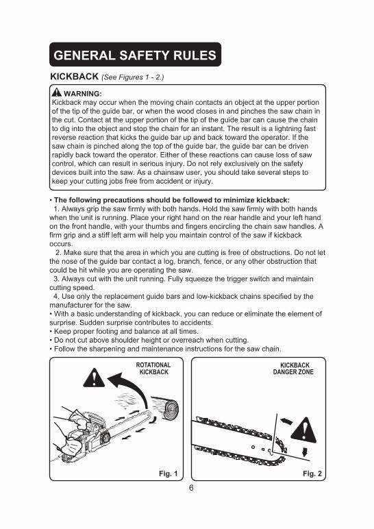
WARNING:
KICKBACK (See Figures 1 - 2.)
ROTATIONALKICKBACK
KICKBACKDANGER ZONE
Fig. 1 Fig. 2

7
GENERAL SAFETY RULES
(See Figure 3.)
PULL
PUSH
Fig. 3

8
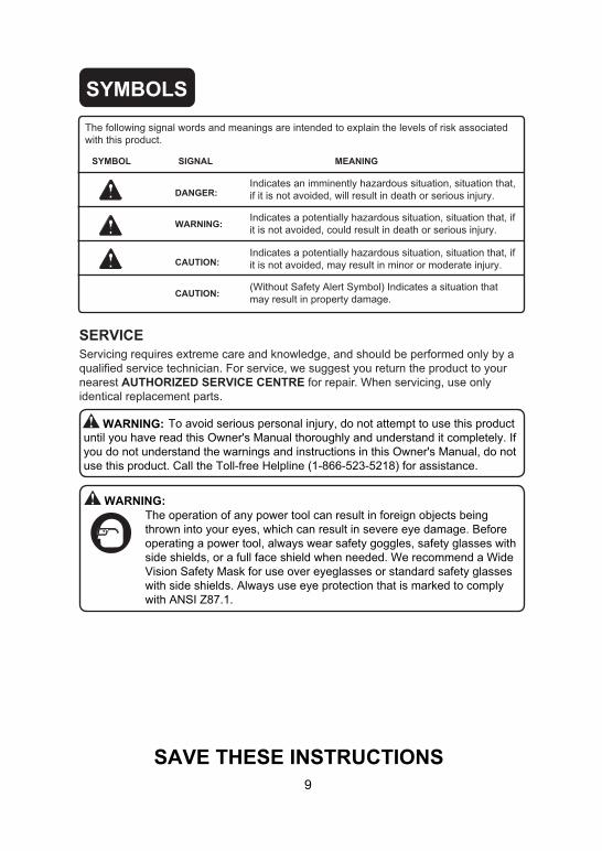
SYMBOLS
SYMBOL NAME DESIGNATION/EXPLANATION
V Volts VoltageA Amperes CurrentHz Hertz Frequency (cycles per second)W Watts Power
min Minutes TimeAlternating Current Type of current
Do not expose to rain or use in damp locations.
Direct Current Type or a characteristic of current
Rotational speed, at no loadno No Load Speed
Class II Construction Double-insulated construction
.../min Per Minute Revolutions, strokes, surface speed, orbits etc., per minute
Wet Conditions Alert
Read The Owner's Manual
To reduce the risk of injury, user must read andunderstand operator’s manual before using this product.
Eye and HeadProtection
Wear eye and head protection when operating thisequipment.
Safety Alert Precautions that involve your safety.
Operate With TwoHands
Hold and operate the saw properly with both hands.
One Handed Do not operate the saw using only one hand.
Kickback DANGER! Beware of kickback,precautions the Kickback involve your safety.
Bar Nose Contact Avoid bar nose contact.
Wear Gloves Wear non-slip, heavy-duty protective gloves whenhandling the chainsaw.
Wear Safety Footwear Wear non-slip safety footwear when using this equipment.
Keep Bystanders Away Keep all bystanders and animals at least 50' (15 m) away.
Some of the following symbols may be used on this product. Please study them and learn their meaning. Proper interpretation of these symbols will allow you to operate the product better and safer.


KNOW YOUR CHAINSAW
12
Fig. 5
FRONT HAND GUARD
FRONTHANDLE
OIL RESERVOIRCAP
CHAIN COVER
REARHANDLE
GUIDEBAR
LOW-KICKBACKSAW CHAIN
TRIGGERSWITCH
SCABBARD
CHAIN TENSIONING KNOBCHAIN COVERLOCK KNOB


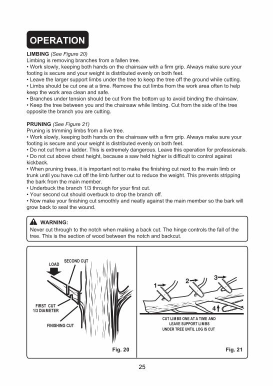
OPERATION
15
APPLICATIONSYou can use this product for the purposes listed below:
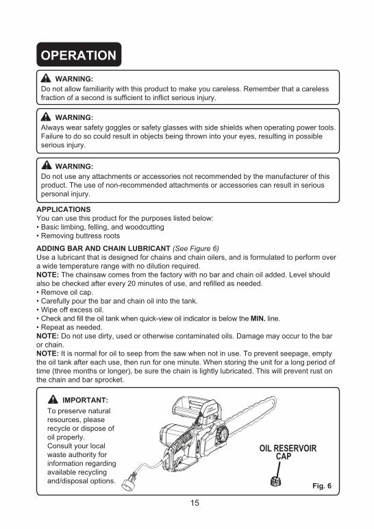
ADDING BAR AND CHAIN LUBRICANT (See Figure 6)
ired.NOTE:
and refilled as needed.
ank.
eck and fill the oil tank when iew oil indicator is below the MIN. line.
NOTE: tor chain.NOTE:
nthe chain and bar sprocket.
WARNING:o
WARNING:s
Failure to do so could result in objects bein
WARNING:
t
OIL RESERVOIR CAP
Fig. 6
NIAHC TNACIRBUL
IMPORTANT:
and/disposal options.

OPERATION
16
CONNECTING TO POWER SUPPLY (See Figure 7)This chainsaw is designed with a cord retainer that prevents the extension cord from being pulled loose while using.
he opening in the side of the rear handle, and place over cord hitch.
slack is removed.
NOTE: from extension cord retainer could result in plug loosening from receptacle.
Fig. 7
EXTENSIONCORD
PERAT N
17
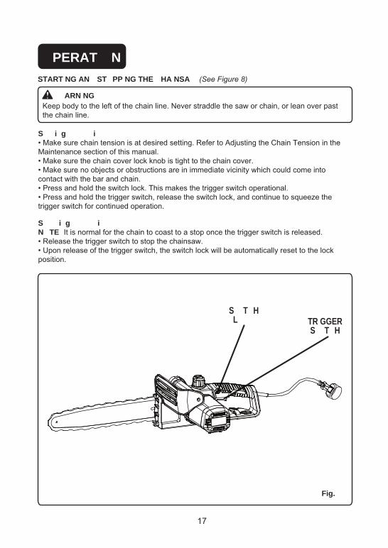
START NG AN ST PP NG THE HA NSA (See Figure 8)
ARN NGKeep body to the left of the chain line. Never straddle the saw or chain, or lean over past the chain line.
S i g ig
to the chain cover.i
contact with the bar and chain.the trigger switch operational.e
S i g iN TE top once the trigger switch is released.
saw.
position.
Fig.
TR GGERS T H
S T HL

OPERATION
18
PREPARING FOR CUTTINGPROPER GRIP ON HANDLES (See Figure 9)See General Safety Rules for appropriate safety equipment.
rotection.ky
noa
cause loss of control.
WARNING:r
WARNING:
io
PROPER HAND GRIP POSITION
Fig. 9
CHAINLINE

OPERATION
19
PROPER CUTTING STANCE (See Figure 10)
BASIC OPERATING/CUTTING PROCEDURES
STRAIGHTARMCHAIN LINETHUM B ON
UNDERSIDE OFHANDLE BAR
Fig. 10


OPERATION
23
REMOVING BUTTRESS ROOTS (See Figure )A buttress root is a large root extending from the trunk of the tree above the ground. Remove large buttress roots prior to felling. Make the horizontal cut into the buttress first, followed by the vertical cut. Remove the resulting loose section from the work area. Follow the correct tree felling procedure as stated in Proper Procedure For Tree Felling after you have removed the large buttress roots.
BUCKING (See Figure )Bucking is the term used for cutting a fallen tree to the desired log length.
your weight is distributed evenly on both feet.
log while bucking.cts can contact the guide bar nose and chain
during cutting, because this can cause kickback. e uphill side of the log. To maintain complete
control of the chainsaw when cutting through the log, release the cutting pressure near the end of the cut without relaxing your grip on the chainsaw handles. Do not let the chain contact the ground. After completing the cut, wait for the saw chain to stop before you move the chainsaw. Always stop the motor before moving from tree to tree.
HORIZONTALCUT
VERTICALCUT
LOOSESECTION
KICKBACK
PULL
Fig. 14 Fig. 15
PULL

OPERATION
24
BUCKING WITH A WEDGE (See Figure 16)If the wood diameter is large enough for you to insert a soft bucking wedge without touching the chain, you should use the wedge to hold the cut open to prevent pinching.
BUCKING LOGS UNDER STRESS (See Figure 17)Make the first bucking cut 1/3 of the way through the log, and finish with a 2/3 cut on the opposite side. As you cut the log, it will tend to bend. The saw can become pinched or hung in the log if you make the first cut deeper than 1/3 of the diameter of the log.Give special attention to logs under stress to prevent the bar and chain from pinching.
OVERBUCKING (See Figure 18)Begin on the top side of the log with the bottom of the saw against the log; exert light pressure downward. Note that the saw will tend to pull away from you.
UNDERBUCKING (See Figure 19)Begin on the under side of the log with the top of the saw against the log; exert light pressure upward. During underbucking, the saw will tend to push back at you. Be prepared for this reaction, and hold the saw firmly to maintain control.
Fig. 18
WEDGE
Fig. 16
Fig. 17
Fig.19
LOAD
FINISHING CUT
1ST CUT 1/3 DIA
LOG SUPPORTED AT ONE END
LOG SUPPORTED AT BOTH ENDS
FINISHING CUT
1ST CUT 1/3 DIA
LOAD
OVERBUCKING
UNDERBUCKING
PULL
PUSH


MAINTENANCE
27
GENERAL MAINTENANCEAvoid using solvents when cleaning plastic parts. Most plastics are susceptible to damage from various types of commercial solvents. Use a clean cloth to remove dirt, dust, lubricant, grease, etc.
LUBRICATIONAll of the bearings in this product are lubricated with a sufficient amount of high-grade lubricant for the life of the unit under normal operating conditions. Therefore, no further lubrication is required.
WARNING:When servicing, use only identical YARDWORKS replacement parts. Use of any other parts may create a hazard or cause product damage.
WARNING:Always wear safety goggles or safety glasses with side shields during power tool operation or when blowing dust. If operation is dusty, also wear a dust mask.
WARNING:Do not let brake fluids, gasoline, petroleum-based products, penetrating lubricants, etc., come into contact with plastic parts at any time. Chemicals can damage, weaken or destroy plastic, which may result in serious personal injury.
NOTE: When replacing the guide bar and chain, always use the specified bar and chain listed in the Bar and Chain Combinations section later in this manual.
REPLACING THE GUIDE BAR AND CHAIN (See Figure 23-29)
WARNING:To avoid serious personal injury, read and understand all the safety instructions in this section.
WARNING:Before performing any maintenance, make sure the tool is unplugged from the power supply. Failure to heed this warning could result in serious personal injury.
WARNING:Never touch or adjust the chain while the motor is running. The saw chain is very sharp. Always wear protective gloves when performing maintenance involving the chain to avoid possible serious lacerations.
CAUTION:Always wear gloves when handling the bar and chain. These components are sharp and may contain burrs.
DANGER:Never start the motor before installing the guide bar, chain, chain cover, and chain cover lock knob. Without all these parts in place, the clutch can fly off or explode, exposing the user to possible serious injury.

MAINTENANCE
28
Fig. 23
Fig. 25
Fig. 24
CHAIN
Note: When replacing the guide bar and chain always use the specified bar and chain in the
TENSIONINGKNOB
CHAIN COVERLOCK KNOB
CHAIN
BAR
CHAIN
COVER
BAR
CHAINTENSIONINGKNOB
TENSIONBLOCK
TENSIONBLOCK
CHAIN
CHAIN COVERLOCK KNOB
MOUNTINGSURFACE
Bar and Chain combinations section later in this manual.

MAINTENANCE
29
g
NOTE:
NOTE:
BARGROOVE
CHAIN DRIVE LINKS
CUTTERS CHAIN ROTATION
CHAIN DRIVE LINKS
Fig. 26
Fig. 27
Fig. 28
Fig. 29

MAINTENANCE
30
c
NOTE:-
E

MAINTENANCE
31
NOTE:
NOTE:
NOTE:
ADJUSTING THE CHAIN TENSION (See Figure 30-31)
WARNING:
CAUTION:
Fig. 30
Fig. 31
FLATS ON DRIVE LINKS
1/16" (1.3 mm)
MAINTENANCE
32
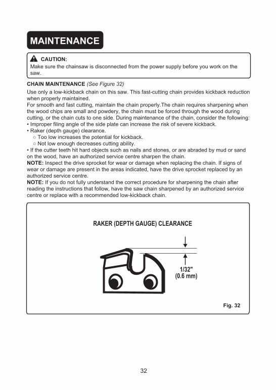
Use only a low-kickback chain on this saw. This fast-cutting chain provides kickback reduction when properly maintained.For smooth and fast cutting, maintain the chain properly.The chain requires sharpening when the wood chips are small and powdery, the chain must be forced through the wood during cutting, or the chain cuts to one side. During maintenance of the chain, consider the following:
on the wood, have an authorized service centre sharpen the chain.NOTE:wear or damage are present in the areas indicated, have the drive sprocket replaced by an authorized service centre.NOTE:reading the instructions that follow, have the saw chain sharpened by an authorized service centre or replace with a recommended low-kickback chain.
CHAIN MAINTENANCE (See Figure 32)
CAUTION:Make sure the chainsaw is disconnected from the power supply before you work on the saw.
Fig. 32
RAKER (DEPTH GAUGE) CLEARANCE
1/32"(0.6 mm)

MAINTENANCE
33
Be careful to file all cutters to the specified angles and to the same length, because fast cutting can only be obtained when all cutters are uniform.
Use a 5/32" (4 mm) diameter round file and holder. Do all of your filing at the midpoint of the bar.
SHARPENING THE CUTTERS (See Figure 33-36)
CAUTION:r
saw.
WARNING:
s
Fig. 33
Fig. 34
Fig. 35
Fig. 36
CUTTINGCORNER
SIDE PLATE
DEPTH GAUGE
TOE
GULLET
HEEL
RIVET HOLE
TOP PLATE
LEFT- HANDCUTTERS
RIGHT-HANDCUTTERS

MAINTENANCE
35
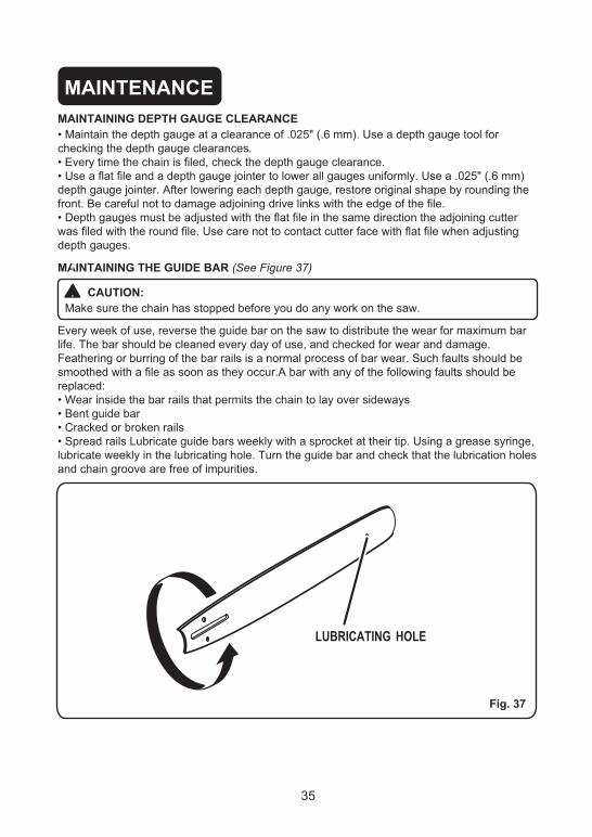
MAINTAINING THE GUIDE BAR (See Figure 37)
MAINTAINING DEPTH GAUGE CLEARANCE
CAUTION:
Fig. 37
LUBRICATING HOLE


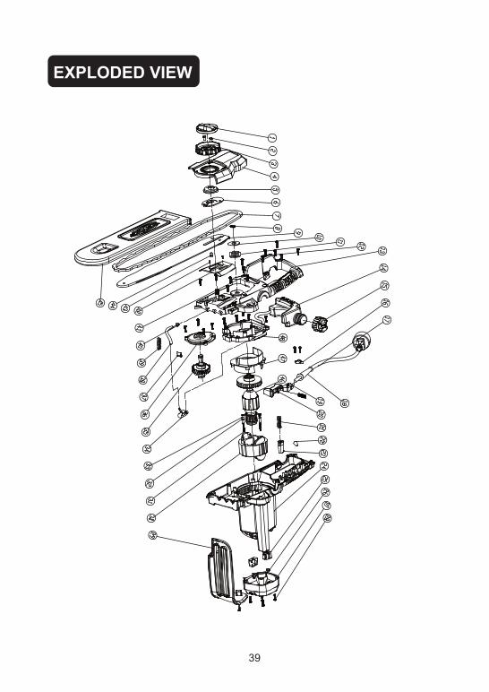
EXPLODED VIEW
39

PARTS LIST
40
1
34567891011121314151617181920212223242526
ITEM # PART NO. QTY DESCRIPTION34102324
3390140533310405311304053290875333023243330210233902102322050431104405-23110232431105403341080131106405342094023630115434109405-2
3650416134110405-234101405-2311014053420240534104405322010734108405
1
11111111111111111
121221271
Knob board2 32210405 2 Bolts
34103324 1 Tension knob
Tension wheelsTension knob boradChainWashersBarWashersChain wheelBoltsRight housing assemblyOil tankCapWire boardPower cordWire sleeveSwitchTrigger
Tie-in33204403 2 Spring
Lock-buttonLeft housingCarbon brush assemblyCarbon brush boardMotor coverScrew ST4.2*14-F
34101324 Side cover
Front baffleStator assembly
27282930313233343536373839
3111040532202155
1Screw ST4.2*45-F2
329024043290140434901154
221
Washer
34112405 1 Oil pump board
SpringOil pump assembly
31103324 1 Out-put shaft assembly
34204405 1 Flown line32902405 1 Oil tube spring
34105405 1 Gear-down box upper cover

41
40
4342
444546
DESCRIPTION32209405
3410432431111405
132209302 1
111
Oil tube springScrew41
33312405 1 Bar pitch3221675A 2 Screw ST3*12-C
ScabbardRotor assembly
32208405 Bolt
4748 31103405
11 Gear down box under cover
34111405 Washer
PARTS LIST
ITEM # PART NO. QTY