electric heat tracing heat tracing proposed power connection location cable allowance for in-line...
TRANSCRIPT

INSTALLATION, MAINTENANCE, & TROUBLESHOOTING
Electric Heat Tracing

2
3
About These InstructionsThe installation instructions within this document describe the installation of Thermon trace heating systems in typical piping applications and are suitable for use with the flexible trace heating products listed on this page.
These instructions are not intended for mineral- insulated (MI) trace heaters. Instructions and documentation for other products and applications may be found at www.thermon.com.
For translations of this document in languages other than English, please contact Thermon. The English language version of this document shall govern.
IMPORTANT: To maintain warranty coverage of the trace heating system, the steps in these installation instructions, including testing, must be followed and documented on the Installation Report (page 11), wherever required in the text.
Safety and Site Practice• Installation shall be carried out under the supervision
of a qualified person.
• Persons involved in the installation and testing of electric trace heating systems shall be suitably trained in all special techniques required, including:
• the purpose and function of the electrical trace heating system,
• its associated power supply and control equipment, and
• how to recognize and avoid the hazards associated with its operation and maintenance.
• All personnel shall use all appropriate personal protective equipment (PPE), including protective clothing, to protect against potential arc flash and shock hazards.
• All personnel shall comply with all applicable safety and health guidelines, including Thermon requirements, the regulations outlined in the NEC and CEC, and EN/IEC/IEEE 60079-30-2 for hazardous areas (as applicable), and any other applicable national and local electric codes.
• During installation, the trace heating system parameters shall be verified. Tests shall be performed in the field and documented in the Installation Report (page 11) as instructed.
For insulated externally heated surfaces, lower T-class systems may be obtained by utilizing stabilized designs or controlled designs using methods described in IEC/IEEE/EN 60079-30-1, Clause 4.5, using CompuTrace Electric Heat Tracing Design Software or by Thermon Engineering.
Types of Heating Cables Self-Regulating Heating Cables: BSX™ Self-Regulating Heating Cable
(refer to Form TEP0067)
RSX™ Self-Regulating Heating Cable (refer to Form TEP0004)
KSX™ Self-Regulating Heating Cable (refer to Form TEP0072)
HTSX™ Self-Regulating Heating Cable (refer to Form TEP0074)
VSX™ Self-Regulating Heating Cable (refer to Form TEP0008)
VSX-HT™ Self-Regulating Heating Cable (refer to Form TEP0208)
Power-Limiting Heating Cable: HPT™ Power-Limiting Heating Cable
(refer to Form TEP0011)
Parallel Constant Watt Heating Cable: FP Parallel Constant Watt Heating Cable
(refer to Form TEP0016)
Series Constant Watt Heating Cables: TEK™ Series Constant Watt Heating Cable
(refer to Form TEP0021)
HTEK™ Series Constant Watt Heating Cable (refer to Form TEP0022)
The National Electric Code and Canadian Electrical Code require ground-fault protection be provided for electric heat tracing .

4
Trace Heating System Design • The design of electrical resistance trace heating
systems shall be overseen by persons knowledgeable of trace heating, following the design methodology for explosive atmospheres as specified by Thermon Engineering or CompuTrace Electric Heat Tracing Design Software.
• For insulated externally heated surfaces, lower T-class systems may be obtained by utilizing stabilized designs or controlled designs using methods described in IEC/IEEE/EN 60079-30-1, Clause 4.5, using CompuTrace Electric Heat Tracing Design Software or by Thermon Engineering. The system design parameters, including the resulting T-class, shall be retained as a record of system documentation for each design for at least as long as the system is in use. The parameters in the system documentation shall be checked during commissioning of the system.
Illustration A: Typical Trace Heating Installation
8
5
4
6
5a
1
2
3
7
• The stabilized design method may be used for self-regulating, power-limiting, and constant-watt heating cables without a limiting device.
• Series heating cable output and T-rating are dependent upon several variables, including supply voltage, cable resistance, and temperature conditions.
Complete Electric Heat Tracing SystemA complete electric heat tracing system will typically include the following components1:
1. Electric heat tracing cable2 (self-regulating, power-limiting, parallel constant watt or series constant watt).
2. Power connection kit.
3. RTD sensor or control thermostat3.
4. In-line/T-splice kit (permits two or three cables to be spliced together).
5. Cable end termination.
6. Attachment tape (use on 12” (30 cm) intervals or as required by code or specification).
7. “Electric Heat Tracing” label (peel-and-stick label attaches to insulation vapor barrier on 10’ intervals or as required by code or specification).
8. Thermal insulation4 and vapor barrier (by others).
The absence of any of these items can cause a system to malfunction or represent a safety hazard.
Notes1 See Page 3 for trace heater types and references for approvals.2 Power connections must be used with correctly-installed certified
enclosures that are suitable for the application (such as Terminator™). When connecting certified terminals using associated accessories, the required creepage distances and clearances shall be observed.
3 Temperature control is recommended for all freeze-protection and temperature-maintenance trace heating applications.
4 All heat-traced lines must be thermally insulated.
5
Upon Receiving the Trace Heater1. Make sure that the correct type (including the correct
nominal power output and voltage level) has been received.
All flexible trace heaters, of the types covered in this document, are printed with the catalog number, voltage rating and power output (in W/m or W/ft) on the jacket. To verify the year of construction, please contact Thermon with the batch code number printed on the trace heater jacket.
2. Record the reel number, reel length, trace heater type, and nominal power output and voltage in the Pre-Installation section of the Installation Report (page 11).
3. Visually inspect cable for any damage incurred during shipment. Note any observed damage in the Installation Report.
4. Perform the Insulation Resistance (IR) Test, described on this page, to confirm the trace heater’s electrical integrity. Record the reading in the Installation Report.
5. Store the trace heater in a dry location.
Before Installing• Be sure all piping and equipment to be traced have
been completely installed and pressure-tested.
• Ensure that all surface areas where the trace heater is to be installed are reasonably clean. Remove any dirt, rust, and scale with a wire brush. Remove oil and grease films with a suitable solvent.
• De-energize power sources before installation.
• Keep ends of trace heaters and kit components dry before and during the installation.
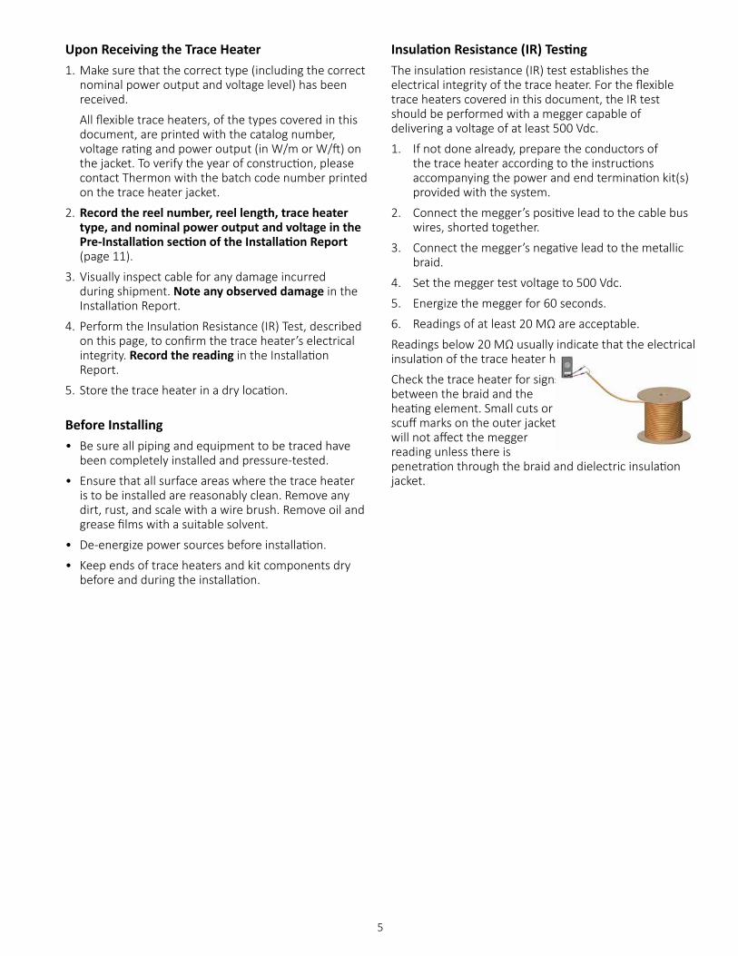
Insulation Resistance (IR) TestingThe insulation resistance (IR) test establishes the electrical integrity of the trace heater. For the flexible trace heaters covered in this document, the IR test should be performed with a megger capable of delivering a voltage of at least 500 Vdc.
1. If not done already, prepare the conductors of the trace heater according to the instructions accompanying the power and end termination kit(s) provided with the system.
2. Connect the megger’s positive lead to the cable bus wires, shorted together.
3. Connect the megger’s negative lead to the metallic braid.
4. Set the megger test voltage to 500 Vdc.
5. Energize the megger for 60 seconds.
6. Readings of at least 20 MΩ are acceptable.
Readings below 20 MΩ usually indicate that the electrical insulation of the trace heater has been compromised.
Check the trace heater for signs of physical damage between the braid and the heating element. Small cuts or scuff marks on the outer jacket will not affect the megger reading unless there is penetration through the braid and dielectric insulation jacket.
6
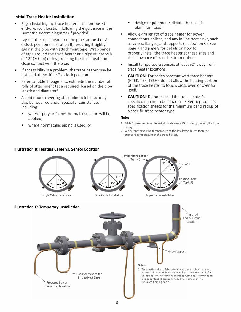
Initial Trace Heater Installation• Begin installing the trace heater at the proposed
end-of-circuit location, following the guidance in the isometric system diagrams (if provided).
• Lay out the trace heater on the pipe, at the 4 or 8 o’clock position (Illustration B), securing it tightly against the pipe with attachment tape. Wrap bands of tape around the trace heater and pipe at intervals of 12” (30 cm) or less, keeping the trace heater in close contact with the pipe.
• If accessibility is a problem, the trace heater may be installed at the 10 or 2 o’clock position.
• Refer to Table 1 (page 7) to estimate the number of rolls of attachment tape required, based on the pipe length and diameter1.
• A continuous covering of aluminum foil tape may also be required under special circumstances, including:
• where spray or foam2 thermal insulation will be applied,
• where nonmetallic piping is used, or
Proposed Power Connection Location
Cable Allowance for In-Line Heat Sinks
Pipe Support
Proposed End-of-Circuit
Location
Illustration C: Temporary Installation
Notes . . .
1. Termination kits to fabricate a heat tracing circuit are not addressed in detail in these installation procedures. Refer to installation instructions included with cable termination kits or contact Thermon for specific instructions to fabricate heating cable.
Illustration B: Heating Cable vs. Sensor Location
Heating Cable (Typical)
Pipe Wall
Temperature Sensor (Typical)
45°45°
45° 45°45°
90°
45°
45°90°
Single Cable Installation Triple Cable InstallationDual Cable Installation
• design requirements dictate the use of aluminum tape.
• Allow extra length of trace heater for power connections, splices, and any in-line heat sinks, such as valves, flanges, and supports (Illustration C). See page 7 and page 8 for details on how to properly install the trace heater at these sites and the allowance of trace heater required.
• Install temperature sensors at least 90° away from trace heater locations.
• CAUTION: For series constant-watt trace heaters (HTEK, TEK, TESH), do not allow the heating portion of the trace heater to touch, cross over, or overlap itself.
• CAUTION: Do not exceed the trace heater’s specified minimum bend radius. Refer to product’s specification sheets for the minimum bend radius of a specific trace heater type.
Notes
1 Table 1 assumes circumferential bands every 30 cm along the length of the piping.
2 Verify that the curing temperature of the insulation is less than the exposure temperature of the trace heater.
7
Illustration D: Pipe Elbow
Illustration F: Pipe Flange
Heating Cable
Attachment Tape(Typical)
Illustration E: Uninsulated Pipe Support
Attachment Tape(Typical)
Heating Cable
12” Max. (30 cm)Note: Flange allowance will vary
based on method of insulating flange and adjacent piping.
Support Length
Attachment Tape(Typical)
Heating Cable
3” Min. (8 cm)
3” Min. (8 cm)
Note . . .
1. Only applicable for pipe ≥ 50mm.
Circuit Layout on Support
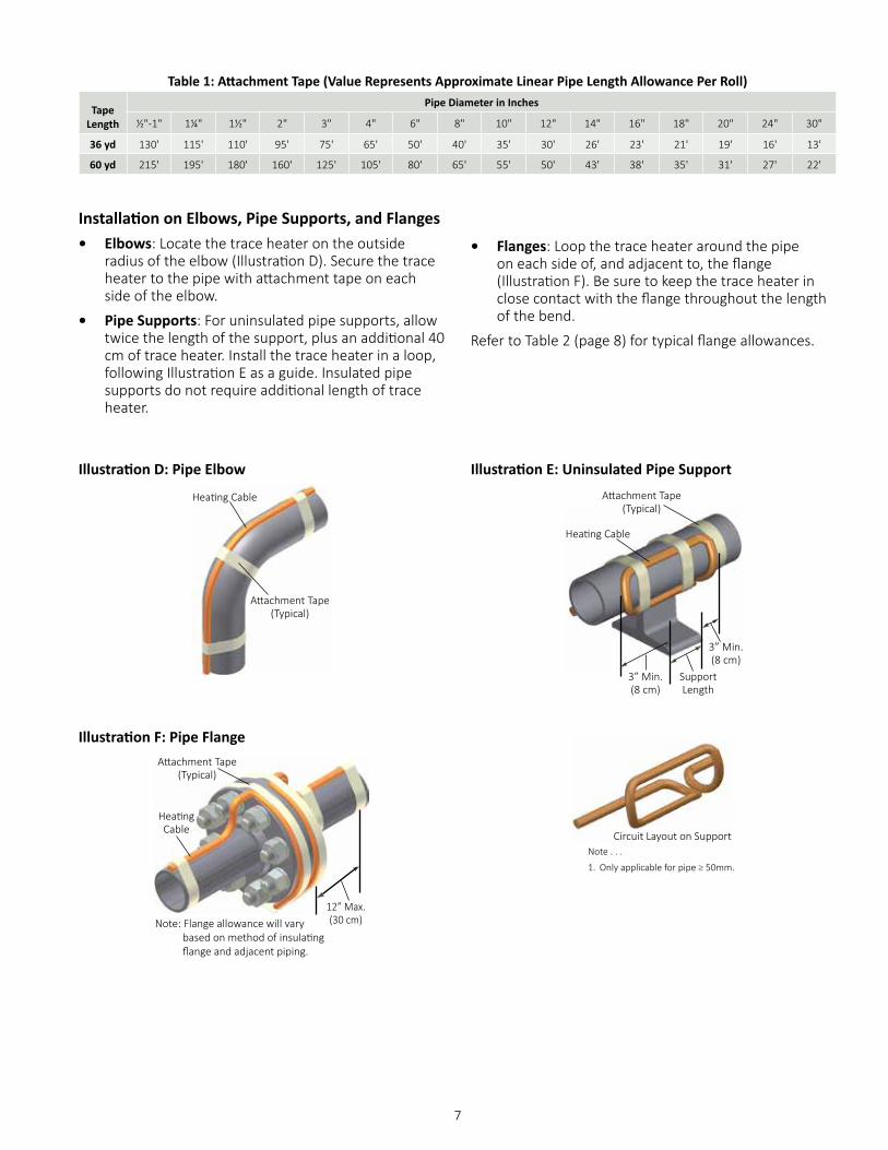
Installation on Elbows, Pipe Supports, and Flanges• Elbows: Locate the trace heater on the outside
radius of the elbow (Illustration D). Secure the trace heater to the pipe with attachment tape on each side of the elbow.
• Pipe Supports: For uninsulated pipe supports, allow twice the length of the support, plus an additional 40 cm of trace heater. Install the trace heater in a loop, following Illustration E as a guide. Insulated pipe supports do not require additional length of trace heater.
• Flanges: Loop the trace heater around the pipe on each side of, and adjacent to, the flange (Illustration F). Be sure to keep the trace heater in close contact with the flange throughout the length of the bend.
Refer to Table 2 (page 8) for typical flange allowances.
Table 1: Attachment Tape (Value Represents Approximate Linear Pipe Length Allowance Per Roll)
TapeLength
Pipe Diameter in Inches
½"-1" 1¼" 1½" 2" 3" 4" 6" 8" 10" 12" 14" 16" 18" 20" 24" 30"
36 yd 130' 115' 110' 95' 75' 65' 50' 40' 35' 30' 26' 23' 21' 19' 16' 13'
60 yd 215' 195' 180' 160' 125' 105' 80' 65' 55' 50' 43' 38' 35' 31' 27' 22'
8
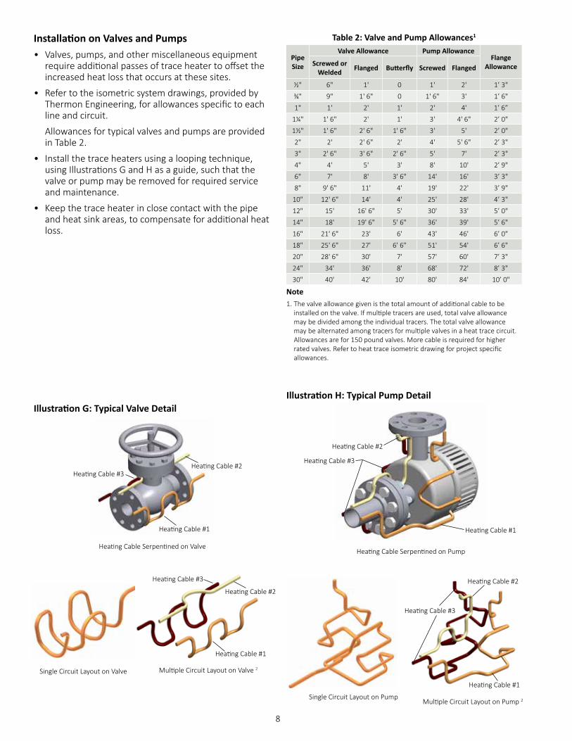
Illustration G: Typical Valve Detail
Installation on Valves and Pumps• Valves, pumps, and other miscellaneous equipment
require additional passes of trace heater to offset the increased heat loss that occurs at these sites.
• Refer to the isometric system drawings, provided by Thermon Engineering, for allowances specific to each line and circuit.
Allowances for typical valves and pumps are provided in Table 2.
• Install the trace heaters using a looping technique, using Illustrations G and H as a guide, such that the valve or pump may be removed for required service and maintenance.
• Keep the trace heater in close contact with the pipe and heat sink areas, to compensate for additional heat loss.
Illustration H: Typical Pump Detail
Heating Cable Serpentined on Pump
Single Circuit Layout on Valve Multiple Circuit Layout on Valve 2
Heating Cable #1
Heating Cable #2
Heating Cable #3
Heating Cable #1
Heating Cable #3
Heating Cable #2
Heating Cable #1
Heating Cable #3
Heating Cable #2
Single Circuit Layout on PumpMultiple Circuit Layout on Pump 2
Heating Cable #1
Heating Cable #2Heating Cable #3
Heating Cable Serpentined on Valve
Table 2: Valve and Pump Allowances1
Pipe Size
Valve Allowance Pump AllowanceFlange
AllowanceScrewed or Welded Flanged Butterfly Screwed Flanged
½" 6" 1' 0 1' 2' 1’ 3"
¾" 9" 1' 6" 0 1' 6" 3' 1’ 6"
1" 1' 2' 1' 2' 4' 1’ 6”
1¼" 1' 6" 2' 1' 3' 4' 6" 2’ 0"
1½" 1' 6" 2' 6" 1' 6" 3' 5' 2’ 0"
2" 2' 2' 6" 2' 4' 5' 6" 2’ 3"
3" 2' 6" 3' 6" 2' 6" 5' 7' 2’ 3"
4" 4' 5' 3' 8' 10' 2’ 9"
6" 7' 8' 3' 6" 14' 16' 3’ 3"
8" 9' 6" 11' 4' 19' 22' 3’ 9"
10" 12' 6" 14' 4' 25' 28' 4’ 3"
12" 15' 16' 6" 5' 30' 33' 5’ 0"
14" 18' 19' 6" 5' 6" 36' 39' 5’ 6"
16" 21' 6" 23' 6' 43' 46' 6’ 0"
18" 25' 6" 27' 6' 6" 51' 54' 6’ 6"
20" 28' 6" 30' 7' 57' 60' 7’ 3"
24" 34' 36' 8' 68' 72' 8’ 3"
30" 40' 42' 10' 80' 84' 10’ 0"
Note1. The valve allowance given is the total amount of additional cable to be
installed on the valve. If multiple tracers are used, total valve allowance may be divided among the individual tracers. The total valve allowance may be alternated among tracers for multiple valves in a heat trace circuit. Allowances are for 150 pound valves. More cable is required for higher rated valves. Refer to heat trace isometric drawing for project specific allowances.
9
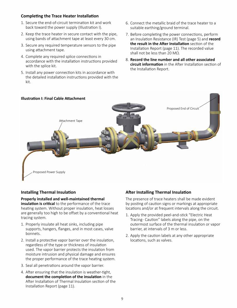
Completing the Trace Heater Installation1. Secure the end-of-circuit termination kit and work
back toward the power supply (Illustration I).
2. Keep the trace heater in secure contact with the pipe, using bands of attachment tape at least every 30 cm.
3. Secure any required temperature sensors to the pipe using attachment tape.
4. Complete any required splice connections in accordance with the installation instructions provided with the splice kit.
5. Install any power connection kits in accordance with the detailed installation instructions provided with the kit.
Installing Thermal InsulationProperly installed and well-maintained thermal insulation is critical to the performance of the trace heating system. Without proper insulation, heat losses are generally too high to be offset by a conventional heat tracing system.
1. Properly insulate all heat sinks, including pipe supports, hangers, flanges, and in most cases, valve bonnets.
2. Install a protective vapor barrier over the insulation, regardless of the type or thickness of insulation used. The vapor barrier protects the insulation from moisture intrusion and physical damage and ensures the proper performance of the trace heating system.
3. Seal all penetrations around the vapor barrier.
4. After ensuring that the insulation is weather-tight, document the completion of the insulation in the After Installation of Thermal Insulation section of the Installation Report (page 11).
After Installing Thermal InsulationThe presence of trace heaters shall be made evident by posting of caution signs or markings at appropriate locations and/or at frequent intervals along the circuit.
1. Apply the provided peel-and-stick “Electric Heat Tracing - Caution” labels along the pipe, on the outermost surface of the thermal insulation or vapor barrier, at intervals of 3 m or less.
2. Apply the caution labels at any other appropriate locations, such as valves.
6. Connect the metallic braid of the trace heater to a suitable earthing/ground terminal.
7. Before completing the power connections, perform an Insulation Resistance (IR) Test (page 5) and record the result in the After Installation section of the Installation Report (page 11). The recorded value shall not be less than 20 MΩ.
8. Record the line number and all other associated circuit information in the After Installation section of the Installation Report.
Illustration I: Final Cable Attachment
Proposed End of Circuit
Attachment Tape
Proposed Power Supply

10
Final Inspection1. After installing the thermal insulation and vapor
barrier BUT BEFORE ENERGIZING THE CIRCUIT, repeat the IR test to verify that the trace heater has not been damaged during installation. Record the IR value in the After Installation of Thermal Insulation section of the Installation Report (page 11).
2. For Series Heating Cables, measure the electric loop resistance and record the resistance values in the Installation Report.
3. Ensure that all junction boxes, temperature controllers, cable glands, etc., are properly secured.
4. If a temperature controller is used, force the circuit on and energize the circuit at the rated voltage.
5. After 5 minutes, measure the voltage, current, pipe temperature, and ambient temperature. Record these values in the Final Commissioning section of the Installation Report.
6. If a control device is used, verify its settings to ensure that the maximum surface temperature does not exceed the system T-rating, in accordance with IEC/IEEE/EN 60079-30-1, Clause 4.
Documentation RetentionThe trace heating system documentation shall be retained for each trace heating circuit for as long as the system is in use. This includes:
• System Design Parameters And T-Class
• Isometric Circuit Diagrams
• Maintenance Records
• Operating History
• These Instructions
• All Other Documentation Provided By Thermon
Circuit Protection Requirements• Each branch circuit must use over-current protection
that isolates all appropriate power conductors from the supply (typically circuit breakers).
• Ground fault equipment protection is required for each circuit.
• For typical installations (with TT and TN grounding systems), the means of protection must include a residual current protective device for each branch circuit.
• For fixed-level earth/ground-fault circuit interrupters, a minimum 30 mA trip level is recommended. The preferred trip level for adjustable devices is 30 mA above any inherent capacitive leakage characteristic of the heater, as specified by Thermon Engineering.
• Where conditions of maintenance and supervision ensure that only qualified persons will service the installed systems, and continued circuit operation is necessary for the safe operation of the equipment or processes, ground-fault detection without interruption is acceptable if alarmed in a manner to assure an acknowledged response.
• For IT grounding systems, a means of protection against ground faults is required that includes an electrical insulation monitoring device that shall disconnect the supply whenever the electrical resistance is not greater than 50 ohms/volt of rated voltage.
11
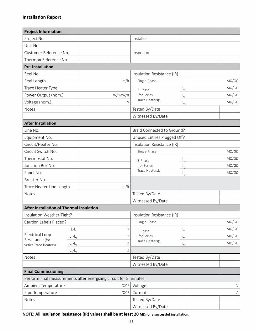
Installation Report
Project InformationProject No. Installer
Unit No.
Customer Reference No. Inspector
Thermon Reference No.
Pre-InstallationReel No. Insulation Resistance (IR)
Reel Length m/ft Single-Phase: MΩ/GΩ
Trace Heater Type 3-Phase (for Series Trace Heaters):
L1MΩ/GΩ
Power Output (nom.) W/m/W/ft L2MΩ/GΩ
Voltage (nom.) V L3MΩ/GΩ
Notes Tested By/Date
Witnessed By/Date
After InstallationLine No. Braid Connected to Ground?
Equipment No. Unused Entries Plugged Off?
Circuit/Heater No. Insulation Resistance (IR)
Circuit Switch No. Single-Phase: MΩ/GΩ
Thermostat No. 3-Phase (for Series Trace Heaters):
L1MΩ/GΩ
Junction Box No. L2MΩ/GΩ
Panel No. L3MΩ/GΩ
Breaker No.
Trace Heater Line Length m/ft
Notes Tested By/Date
Witnessed By/Date
After Installation of Thermal InsulationInsulation Weather-Tight? Insulation Resistance (IR)
Caution Labels Placed? Single-Phase: MΩ/GΩ
Electrical Loop Resistance (for Series Trace Heaters)
L-L Ω 3-Phase (for Series Trace Heaters):
L1MΩ/GΩ
L1-L2Ω L2
MΩ/GΩ
L2-L3Ω L3
MΩ/GΩ
L3-L1Ω
Notes Tested By/Date
Witnessed By/Date
Final CommissioningPerform final measurements after energizing circuit for 5 minutes.
Ambient Temperature °C/°F Voltage V
Pipe Temperature °C/°F Current A
Notes Tested By/Date
Witnessed By/Date
NOTE: All Insulation Resistance (IR) values shall be at least 20 MΩ for a successful installation.
12
Troubleshooting GuideThis troubleshooting guide aims to help to diagnose and resolve many issues on-site.
Many problems with electric trace heating systems can be attributed to two causes:
• Wet, damaged, or missing insulation. Visually inspect the insulation along the entire length of the circuit, making sure that it is intact and dry throughout.
• Physical damage incurred from recent repairs and maintenance to any in-line or nearby equipment.
Symptom Possible Cause RemedyNo heat/no current • Loss of power/voltage • Check the circuit breaker and electrical
connections• Controller setpoint too low • Verify/adjust setpoint• High-temperature limit switch activated • May require manual reset to re-enable
trace heating circuit• “Open” series heating circuit • Repair or replace circuit1
• Controller failure • Repair sensor or controller2
Before maintenance, repair, or modificationCAUTION: Consult the trace heating system documentation prior to maintenance, repair, or modification.
1. Identify the circuit or equipment to be de-energized and all possible sources of electrical energy supplies to the specific circuit and equipment.
2. De-energize all power sources.
3. Apply lockout/tagout devices according to established procedures.
4. Test for the absence of voltage with an approved voltmeter (where the voltmeter is tested on a known circuit voltage prior to and immediately following application).
5. For protection against the accidental energizing of supply conductors, apply temporary jumpers rated for the available fault duty between each supply conductor and earth/ground.
NOTE: In the event of an ground fault or over-current interruption, devices shall not be reset until the cause of the trip has been investigated by qualified personnel.
After maintenance, repair, or modification1. Test the operation of each affected circuit.
2. The insulation resistance of the trace heater shall be measured and recorded and shall not be less than 20 MΩ.
3. Visually verify that all circuit-disconnect devices are open before reconnecting power.
Maintenance and Repair• Once the system has been successfully installed, an
ongoing preventive maintenance program should be implemented, using qualified personnel. The trace heating system should be inspected and tested on a regular basis, at least once per year.
• Keep records of the operating and maintenance history for each circuit, including all test results performed during maintenance and inspection. Record-keeping during scheduled maintenance will help to establish a “normal” range of operation. Insulation resistance readings that deviate from the normal range may indicate problems with a circuit.
• If the system fails any test, refer to the troubleshooting guide below to address the issue. De-energize the affected circuits and make the necessary repairs immediately.
Other possible causes are listed below, with their symptoms and potential remedies.
If any circuit is suspected to be damaged, de-energize the circuit and perform the Insulation Resistance Test outlined on page 5. Readings below 20 MΩ indicate that the trace heater may be physically damaged.

13
Symptom Possible Cause RemedyLow system temperature • Controller setpoint too low • Verify/adjust setpoint
• Temperature sensor located too close to trace heater or other heat source; may be accompanied by excessive cycling of control relays/contacts
• Relocate sensor
• Insulation material and/or thickness different than designed
• Replace insulation; increase insulation thickness (if dry); review design3
• Ambient temperature lower than designed
• Install higher-output trace heater; increase insulation thickness; review design3
• Low voltage (check at power connection point)
• Adjust voltage to meet design requirements3
Low temperature in sections
• Wet, damaged, or missing insulation • Repair or replace insulation and barrier• Trace heater damaged • Repair or replace section; splice kits are
available from Thermon• Heat sinks (valves, pumps, pipe
supports, etc.)• Insulate heat sinks or increase passes of
tracing on heat sinks• Significant changes in elevation along
length of the heat-traced pipe• Consider dividing heating circuit into
separate, independently controlled segments
High system temperature
• Controller “on” continuously • Adjust setpoint or replace sensor2
• Controller fails with contacts closed • Replace sensor or controller2
• Sensor located on uninsulated pipe or too close to heatsink
• Relocate sensor to an area representative of conditions along length of pipe
• Backup heating circuit controller “on” continuously
• Adjust setpoint or replace backup controller
Excessive cycling • Temperature sensor located too close to trace heater or other heat source; may be accompanied by low system temperature
• Relocate sensor
• Ambient temperature near controller setpoint
• Temporarily alter controller setpoint
• Connected voltage too high • Lower voltage• Trace heater output too high
(overdesign)• Install lower-output trace heater or lower
the voltage• Controller differential too narrow • Widen the differential or replace controller
to avoid premature contact failureTemperature variations along pipe
• Inconsistent trace heater installation along pipe
• Check consistency of trace heater installation, especially at heat sinks
• Inconsistent trace heater performance • Compare calculated power per unit length (W x A/length) for the measured pipe temperature with designed trace heater output for the same temperature; regional damage to trace heater can cause partial failure
• Unanticipated flow patterns or process operating temperatures
• Redistribute heating circuits to accommodate existing flow patterns; confirm process conditions
Notes1 Flexible, polymer-jacketed trace heaters (such as those covered in this document) may be field-spliced. Mineral-insulated (MI) trace heaters typically require
replacement.2 Mechanical thermostat sensors cannot be repaired or replaced. RTD and thermocouple sensors may be replaced. Some controllers have replaceable contacts/
relays or may require a manual reset if a “trip-off” condition was detected.3 Before making any changes to system parameters, consult Thermon for the impact on trace heater performance.

Corporate Headquarters:100 Thermon Dr • PO Box 609 San Marcos, TX 78667-0609 • Phone: 512-396-5801 • 1-800-820-4328 For the Thermon office nearest you visit us at . . . www.thermon.com
© Thermon, Inc. • Printed in U.S.A. • Information subject to change.Form PN50207-0318