electric motor starters
DESCRIPTION
starting motor techniqueTRANSCRIPT

ANDERSON: ELECTRIC MOTOR STARTERS. 619
ELECTRIC MOTOR STARTERS.
By J. ANDERSON, Member.
(Paper first received 20th August, 1921, and in final form 9th January, 1922; read at THE INSTITUTION 2nd March,before the NORTH-EASTERN CENTRE 21th February, before the DUNDEE SUB-CENTRE 13th March, before the SOUTHMIDLAND CENTRE 15th March, and before the WESTERN CENTRE 15/ May, 1922.)
SUMMARY.
The paper deals with the practical development of anelectric motor starter from the first principles relating tocurrent, torque, and resistance values, to the data requiredby the salesman.
First it describes the method adopted of working in per-centages for all calculations; defines what is meant bystarting, accelerating and running torques; refers to thelack of data regarding starting conditions; and gives tablesof stored energy in rotors, for the normal load torque duringacceleration and for the stored energy of a number oftypical machines.
Accelerations are classified as " natural regular," " naturalirregular," " forced regular," and " forced irregular," andtypical diagrams with automatic contactor and hand-operated starters are shown.
A formula is given for estimating accelerating times andtorques, and the number of notches from the point of viewof breaking capacity is then considered.
The rating of the resistance elements, and points arisingout of continuous and intermittent rating, together withdiagrams for air cooling, and radiation and diffusion curvesfor oil-immersed resistances, are next dealt with.
Certain difficulties for the salesman in tabulating thehorse-power and resistance sizes are referred to, and thenecessity of higher standard temperature-rises is urged.
Unbalanced rotor currents and the methods of calculatingsuitable resistance values are dealt with, and the accuracywhich can be obtained on test is shown.
Eddy-current, rheostatic stator, auto-transformer andstar-delta starters are referred to, and the entirely differenttype of current and torque curves obtained are shown.Methods of rapidly determining the starter proportions forvarious duties are given.
Certain points regarding the rating of auto-transformersare raised, and a test showing the effect of unequal tapvoltages is given.
In preparing a paper on the subject of electric motorstarters the mass of material is so great that there isdifficulty in selecting points of sufficient general interestand in limiting the paper to a reasonable length.
To the uninitiated an electric motor starter is thesimplest thing possible ; it merely consists of a resist-ance element, a number of contacts, and a handle whichis operated more or less carefully. To the initiated iipresents an infinity of problems, mechanical, electrical,magnetic, thermal and even chemical. Some of theseare fairly easy of solution, and some are so complexthat only rough working approximations are possible.
It is necessary to review very briefly the varioustypes of starters and describe their fundamentalcharacteristics, but first it is advisable' to deal withcertain terms used in this paper.
It has been found that in a general study it is impos-sible to think of volts, amperes, ohms, horse-power.
torques and speeds in actual values, and it is far easierto consider them as percentages. For instance, 100 percent pressure means the normal line pressure, and 100per cent resistance means that resistance which passesfull-load current at normal line pressure. This resist-ance is represented by the figure 1 because R = E/I
Therefore100 % E100" % I = 1.
If this method is adopted, anything which occurson one motor with a certain ratio of pressure to currentwill occur on any other motor with the same ratio, andthe actual value of the resistance for any motor maybe readily written down.
This statement assumes the characteristic curvesof the two machines to be similar, and this is sufficientlyaccurate for a general study of a given problem.
For example, if it is known from calculations basedon an average series-motor characteristic curve withaverage field and armature resistances, that 60 per centline resistance arid 10 per cent armature diverterresistance gives 10 per cent speed at 80 per cent torque,and the ratings of the two motors are 5 h.p. at 110volts and 40 amperes, and 75 h.p. at 550 volts and110 amperes respectively, the required resistances are :—
For the 5-h.p. motor.
100 per cent resistance = 110/40 = 2-75 ohms,
therefore line resistance (60 per cent) = 1-65 ohms,and armature diverter resistance (10 per cent)= 0-275 ohm.
For the 75-h.p. motor.
100 per cent resistance = 550/110 = 5 ohms,
therefore line resistance (60 per cent) = 3 ohms, andarmature diverter resistance (10 per cent) = 0 - 5 ohm.
The actual speeds reached will differ from 10 percent by the divergence of the actual characteristicsfrom the assumed average, and by the divergence ofthe armature resistances from the assumed average,but corrections are readily introduced when absoluteaccuracy is required. In practice a series of standardcurves is drawn for motors with 2-5, 3, 10 and 15 percent armature resistance.
It is convenient also to assume that percentagetorque and percentage current are synonymous. Thisis practically true for the rotor currents of a.c. slip-ring induction motors, and is sufficiently true for thearmature currents of d.c. shunt machines with normalexcitation, but it is not true for the line currents of

620 ANDERSON : ELECTRIC MOTOR STARTERS.
d.c. series machines or the line currents of a.c. slip-ring and squirrel-cage motors. If the general questionis studied on this assumption, however, it is easy tointroduce corrections for the various types of machines.These methods were adopted some 7 years ago andhave proved invaluable.
The most simple and, theoretically, the perfect formof starter is the liquid type, because it is possible tomove the dippers or alter the level of the electrolyteto vary the resistance at a speed which maintains aconstant accelerating torque with a minimum linecurrent, but so many difficulties arise in practice thatthe step-by-step resistance starter holds the field exceptfor the very largest starters for colliery winders wherethe cost of the various refinements and safeguards issmall relative to the total cost.
The chief difficulties are evaporation of the waterwith creeping of the salt and resulting insulationtroubles, arcing or excessive heating with all resistanceinserted and the dippers just touching the liquid, andheavy current-rush at the moment of short-circuitingthe plates to cut out all the resistance. No doubtthese difficulties can be wholly or partially overcome,but the fact remains that this type constitutes a smallpercentage of the total number of starters in use.
It is necessary at this point to define exactly whatis meant by starting torque, accelerating torque, andrunning torque. It is surprising how loosely engineersuse these terms ; so loosely, indeed, that it is oftendifficult to discover which is really meant, and themotor makers themselves are frequently the worstoffenders. This is probably due to the fact that themotor maker is chiefly concerned with the performanceof his motor on load and at full speed ; the startermaker cares nothing for the performance on full loadand is concerned only with what happens while themotor is accelerating. He requires a different set ofdata from that which the motor maker is in the habitof supplying to his customer, and he experiences veryvery great difficulty in obtaining the data ; he requiresfrom the user a different set of data from that whichthe user is in the habit of giving to the motor maker,and again great difficulty is experienced.
There is abundance of information regarding thepower required to drive different machines on varyingloads, but one looks in vain for data regarding thestarting conditions.
Returning to the definitions : the starting torqueis obviously that iequired to start motion ; it is thetorque required to overcome static friction and may befar in excess of the accelerating and normal runningtorques ; it may vary from day to day with temperature,and is frequently greater on Monday morning than atany other time, on account of all the belts being stiffand cold, and the oil squeezed out of the bearings.
Once motion-has started, the torque falls to thatrequired to produce steady running at a certain speed ;this lower torque is the running torque. If it is desiredto increase the speed, a torque in excess of the runningtorque has to be applied, and this is the true acceleratingtorque ; it may have any value, depending on the timein which it is desired to attain full speed. The runningtorque, from the starter maker's point of view, is
generally the torque required to maintain normal fullspeed at the end of the accelerating period. Thistorque is practically constant throughout the accelera-ting period in the great majority of cases ; there maybe a small difference due to windage and so on at thevarious speeds, but as a rule it is negligible. It has notnecessarily anything to do with the normal full loadof the motor or the overloads to which the motor may
Rating (b.h.p.)of motor
2-55
1015202530405060708090
100125150175200225250275300350400450500550600650
TABLE
Stored Energy
1.
of Rotor.
Stored Energy in ft.-lb. per b.h.p
400/700 r.p.m.
8090
100110120130140150170185200210220230265295330365400430455480520550580600615620630
900/1 000 r.p.m.
90100110125140145155175200230260290320350420—• —
—
—
—
—
—
—
—
. — .
—
—
—
—
at
1300/1500 r.p.m
90100120140170190220280350425480550625690
- — •
—
—
—
—
—
—
—
—
—
—
—
—
—
—
be subjected ; it is generally less than full-load torquebecause it is customary to take off all the load possiblebefore shutting down.
There are numerous exceptions to the general rule,the most notable being centrifugal pumps and fanswhere the running torque at low speed is practicallyonly friction, a matter of 5 to 10 per cent, rising as thesquare of the speed to full-load torque at full speedif the pump is starting against load, or rising to from30 to 50 per cent if the delivery valve is closed andthe pump is merely churning.
The static starting torque is difficult to deal with.

ANDERSON: ELECTRIC MOTOR STARTERS. 621
because no general rules apply; users sometimes com-plain that they have to manipulate the starter to thehalf-way position before the motor starts and thelatter then rushes up to speed ; naturally this musthappen if the initial starting torque is excessive, and theuser must do what he can to reduce it.
The accelerating torque is amenable to exact calcu-
stored in the moving parts at full speed, and to expressthis relatively to the normal horse-power of the motorbecause the starter is the last link in the chain; thesizes of the motor and of the machine it has to drivehave already been determined and all the starter makerhas to do is to supply a starter which will enable thatmotor to run that machine up with the minimum line
TABLE 2.
Friction Torque and Stored Energy for Various Classes of Machinery.
ef. No.
Io
3456789
10
111213
14
1516
17
18
19
20212223242526
Description of work
|
Toothed gearsLoose pulley, as for rotor onlyShop shaftingHoisting full load on cranesHoisting full load on colliery winders . .Small rolls and bar-bending machines . .Medium punching machinesMedium shearing machinesLarge shearing machinesLarge rolling mills
Planing machinesDisc saws for woodBand saws for wood
High-speed disc saws for steel
Travelling motion of a crane with full loadCentrifugal hydro-extractor
Centrifugal pump, valve closed
Centrifugal pump, valve open
Ram pump delivery against vertical headaccumulator
Air compressor starting on by-passHaulage, clutches outHaulage, clutches inConveyorRubber pulping millCorn grinding millLathes and drills
Friction or load torque at end ofaccelerating period
Per cent
20/80 (aver. 45)80/10010010
10/1510/1510/15
5/10/155/10
10/2015/2020/4020/50
.. ' 1\ at start, rising to 20at full speed
75/10035/50 at start, rising to
75/100 at full speed5/7 i at start, rising to
or
30/50 at full speed5/7\ at start, rising to
100 at full speed
100
6
loo1002\100
20/25i
Stored energy at full speed
ft.-lb./b.h.p.
15/18As in Table 1
800/1 0006/7
500/1 000700/1 000
2 0003 000/3 500
14 000/18 000500/1 000
2 000/3 0005 000/8 000
18 000/65 0007 000/10 0001 900/3 8002 500/10 000
(generally 4 000/10 000)14 000/17 000
40060 000/80 000
As in Table 1 for impeller
As in Table 1 for impeller,plus, say, 70 for waterif no long, horizontallengths
100/200
100/200300/900
1 000/2 000.850/1 00050/607 500300
lation ; it depends entirely on the inertia of the movingparts and on the time in which it is desired to run upto speed. If a machine had no inertia there would beno accelerating torque and no accelerating time ; itwould jump to full speed as soon as the running torquewas applied.
It is easiest, from the starter maker's point of view,to think of inertia in terms of the foot-pounds of energy
current in the time required. He may grumble whenconditions are too onerous, or he can draw attentionto them when the specified conditions are impossible,but as a rule he can alter nothing. That is why hetakes the motor and the load as fixed and, in the dailyroutine, works on a motor horse-power percentagebasis.
Further, it is convenient, in a general study, to

622 ANDERSON : ELECTRIC MOTOR STARTERS.
express the stored" energy in terms of foot-pounds permotor brake-horse-power, because the various classesof work become readily recognizable, and the confusioncaused by the actual values is cleared away.
The first place where energy is stored is in thearmature or rotor, and Table 1 gives an idea of theamount to be expected.
These figures are minima, and the actual values fora given motor may be 50 per cent higher ; values forhorse-powers over 650 are not given because sufficientdata are not available. Table 1 has been compiledfrom data of a large number of motors by most of theleading makers, British, American and Continental;
100
The case of colliery winders is different, because thehoisting speeds are high and the stored energy in theload, cages, rope, head-gears and drum is so greatthat the rotor stored energy becomes a small percentageof the total.
The other extreme is reached in hydro-extractors,high-speed saws and rolling-mill work where the rotorstored energy is negligible relative to the total.
A very large number of jobs as actually installedhave been tested, analysed and classified, and Table 2is useful in this connection.
The stored energy of the rotor must be added tothe figures in every case.
25Seconds
FIG. 1.—Torque/time and speed/time curves for 7-notch starter passing 100 per cent current on first notch with motorhaving 66*6 per cent load. Stored energy: 1000 ft.-lb./b.h.p. Motor resistance: 8'8 per cent.
it is not accurate for any particular make of motor,and may be 50 per cent in error in places.
Accuracy is of no great importance because for anaccelerating torque of 50 per cent the acceleratingtimes range from about 0-6 second for 2£ h.p. to 5-5seconds for 650 h.p., and trouble would inevitablyarise if starters were designed for such short acceleratingtimes. In practice it is unwise to design the smallestsection of the smallest starter for less than 10 seconds.In many cases, for example the hoisting motion of acrane, the stored energy of the rotor is all that needbe considered, because the hoisting speeds are so lowthat the stored energy of the load is negligible.
The figures for large rolling mills of the varioustypes differ widely as shown, and it is necessary inevery case to obtain full particulars.
The friction torque for a disc saw rises with thespeed, probably due to churning of the cooling water.
The worst duty is provided by the hydro-extractor,being worse than that of the largest rolling mill rela-tively to the motor size, particularly when the slow-running charging period is taken into account. Manyextractors are started on centrifugal clutches to enablesquirrel-cage motors to be used, but trouble arises ifthese clutches operate too soon, particularly whenstar-delta or auto-transformer starters are used.

ANDERSON: ELECTRIC MOTOR STARTERS. 623
The figure of 60 000 to 80 000 ft.-lb. per b.h.p. isgiven in the table, but it should be mentioned that ifthe total weight of the basket and load is taken withradius of gyration equal to (measured radius X 0-875),values of 205 000 to 256 000 ft.-lb. per b.h.p. areobtained.
Careful tests seem to show this is too high and thatif the weight of the rim, casing and load is taken, theradius of gyration is (measured radius x 0-582), atleast for a 48-inch basket.
Expressed in another way it means that the observedstored energy is only 44-4 per cent of that obtainedby the usually accepted factor.
A great deal of confusion exists as to what con-stitutes light and heavy starting. One user ridiculedthe idea that a high-speed saw could possibly be heavyduty, because he could turn the saw quite easily withone hand. Such a saw takes 62 seconds to run up tospeed with a constant accelerating torque of 100 percent, so that the torque at the beginning must be107-5 per cent and at the end 120 per cent.
A convenient formula to use for these startingproblems is :—
A _ _' ~ T XT X 5-5 X K
where At = accelerating time in seconds ;,S' = stored energy at full speed in foot-pounds
per brake horse-power ;T = percentage of full-load motor torque avail-
able for acceleration ;K = constant depending on the shape of the
acceleration curve, conveniently taken as0-5.
Having reviewed the various classes of work rela-tively to the normal size of motor used for the purpose,and given a rough-and-ready means of estimating theaccelerating time or torque, it is now necessary to seehow these facts can be applied to the starter, and thefirst step is to get a clear idea of the action of a step-by-step starter. For this purpose acceleration may beconveniently classified as follows :—
Natural regular acceleration.Natural irregular acceleration.Forced regular acceleration.Forced irregular acceleration.
When a current is passed through a motor androtation commences, the speed rises until the backelectromotive force cuts down the current to an amountwhich gives rise to a torque just sufficient to overcomethe running friction or load at that speed. When thestarter arm is moved to the next notch to cut outresistance there is a current-rush, the peak of whichis determined by the ratio of the first resistance tothe second, and which gradually dies away as thespeed and back electromotive force rise until balanceis restored and the current corresponding to the runningtorque at the new speed is flowing.
If this is repeated on the third and subsequent notchesand all the peaks and valleys are equal, the accelerationis called " natural regular " ; " regular " because thepeaks and valleys are equal, and " natural " because
the valley current corresponds to the running torqueand cannot be reduced.
Fig. 1 is drawn for a load of 66- 6 per cent, the storedenergy being 1 000 ft.-lb. per b.h.p., the motor resistance8-8 per cent, ratio of resistance from notch to notch1 • 5, and the current on the first notch and on subsequentpeaks being 100 per cent.
160
150
140
130
120
OJ 110
'g 100
-y 90S§ 80o
70
~ 60
1u 50
40
30
20
10
\
\
/
/
Tz&Iz
II1
'——_
\\/J
L
1
T3
Ts&Is
r T+M*3 II1 1_i
JSp-2
[IV
ig s
peed
• r-i
g
t. \^P-7
SP-6
Sp-5
I
i
e an
dI
•
t
Ste<
10 15 20 25Seconds
30 35
FIG. 2.—Torque/time and speed/time curves for starterintended for use under conditions specified in Fig. 1,with motor having 8'8 per cent resistance. Curvesshow effect of using with motor having 3'3 per centresistance.
It is drawn for the correct accelerating time oneach notch arid it will be noted that these times arein proportion to the ratio of the resistances.
The usually accepted formula for this curve is
Ratio =n~l I( total resistance \
kmotor resistance/
where n = number of notches.

624 ANDERSON : ELECTRIC MOTOR STARTERS.
Fig. 2 shows the effect of overestimating the motorresistance; if the actual resistance is lower thanexpected, the current-rush on the last notch may beexcessive and sufficient to bring out the breaker; theoperator may wait on the second last notch for anindefinite period but the breaker will still come out.Incidentally it gives a curve which is typical of" natural irregular acceleration " ; " natural " becausethe valleys fall to the running torque and cannot go
140
130
0 8 12 16 20Seconds
FIG. 3.—Torque/time and speed/time curves for 7-notchstarter passing 100 per cent current on first notch,with motor having centrifugal-pump load starting at7J- per cent and rising to 100 per cent. Stored energy :l"000 ft.-lb/.b.h.p. Motor resistance : 8-8 per cent.
lower, and " irregular " because the peaks are of unequalvalue.
It is essential to know the motor resistance, that is,the resistance of field and armature for a series motor,and of armature only for a shunt motor. By armatureresistance is meant the total resistance including brushgear, commutator and connections, yet even to-day itis not always easy to obtain this information from themotor makers, and a few years ago they seemed tothink they were parting with a vital trade secret whenthey gave it.
The starter maker, in the absence of these data, has
deliberately to underestimate the motor resistance,and this frequently means the addition of anothernotch or two on the starter, with correspondinglyincreased selling price if the larger dial will go in thesame frame, and a very greatly increased price if hehas to use the next larger frame.
There is no correct number of notches for a givenhorse-power because, as a general statement, the greaterthe number of notches the better the starter, but thereis a minimum which should not be exceeded. Thecurrent peaks actually found are never so serious ascalculated, especially with series motors, for severalreasons, the main reason being the inductance of thewindings, particularly that of the field winding, andthis has proved the salvation of many starters. Somuch is this the case that a 5-h.p., 440-volt series motorrunning on a friction load equal to full-load torquemay be switched on and reversed without a starterand without injurious currents or sparking at thecommutator. It would be quite another matter if theload had high stored energy, necessitating starting timesin excess of the time-constant of the circuit.
Fig. 3 shows a better example of natural irregular
HO
Steady running _torque and current
20 25 30
SecondsFJG. 4.—Torque/time and speed/time curves. Conditions
as in Fig. 1, except that motor load is 10 per cent.
acceleration ; it is drawn for a centrifugal pump loadstarting at 7£ per cent and ending at 100 per cent.
Figs. 4 and 5 show the same starter on light andheavy loads respectively, with natural accelerationand the same stored energy, and it will be seen thatthe initial current on the first notch remains as before,but that the peaks and valleys are different and theacceleration is natural regular only after the firstnotch.
Fig. 6 is an example of forced regular accelerationfor the same starter as in Fig. 1, but used on the loadshown in Fig. 4, transition being made from notch to

ANDERSON : ELECTRIC MOTOR STARTERS. 625
notch, not when the valley has fallen to the runningtorque but prematurely when it has fallen to only66 * 6 per cent of this value; the current falls to therunning current only on the last notch when all theresistance is cut out and the operator can no longerinfluence the acceleration. The stored energy is 1 000ft.-lb. per b.h.p. as before, but owing to the increasedtorque available for acceleration the total time isreduced to about 7 "06 seconds instead of 45*75 secondsin Fig. 1. An ammeter should be installed with ared mark at the valley current when it is desired tooperate a starter in this way, and the operator thentraverses the contacts at the right time by passing
140
130
120
110
100
90
80
70
60
50
g 40
20
10
s
Sp-6
-S-i
I-SH
1 H
10 15 20 25 30 35 40 45Seconds
50
FIG. 5.—Torque/time and speed/time curves. Conditions asin Fig. 1, except that motor load is 90 per cent.
from notch to notch when the current falls to themark.
Fig. 7 is an example of forced irregular accelerationand is typical of centrifugal hydro-extractors; it is" forced " in the sense that the valleys are neverallowed to fall to the running torque, and it is " irreg-ular " in that the peaks and valleys are unequal.
Many highly instructive examples could be given,particularly those for reversing rolls driven by alter-nating-current motors where reversal is required inthe shortest possible time, the motor alternately drivingand braking, but that instinctive knowledge of startingconditions which is essential for the starter maker canonly be acquired by each designer working out a seriesof diagrams for himself until it becomes second natureto visualize the curve and say offhand what proportionsmust be used for the job.
Before leaving this part of the subject Figs. 8, 9and 10 should be studied. They have been drawnfor a 15-h.p. Westinghouse motor on a crane. Thesize of the motor was calculated on the basis of 10 foot-tons per b.h.p. and the gears were somewhat moreefficient, thus making full hook load equal to 90 per centof motor torque. The resistance passed 62 per centcurrent (equivalent to 50 per cent torque) on the firstnotch, and a ratio of 2*07 was taken.
Fig. 8 assumes full hook load and an automaticcontactor controller with current relays on all notches,
SecondsFIG. 6.—Torque/time and speed/time curves. Conditions as
in Fig. 4, except that starter is operated to give a peakon each notch equal to that on notch 1, with consequent" forced regular " acceleration.
except notch 1, set for 92 per cent current, equivalentto 90 per cent torque. No motion results and thesecond notch is immediately cut in, the subsequentautomatic operation being as shown, the accelerationbeing natural regular, and each relay operating inturn when the current falls to 92 per cent. The totalaccelerating period is about 2*01 seconds.
Fig. 9 is for the same controller hoisting emptyhook, the load torque being 5 per cent, assuming therelay on the first notch to be set for 36 per cent current(equivalent to 20 per cent torque). The total acceler-ating period up to full speed (273 per cent) is about3-12 seconds, and the acceleration is forced irregular.It will be noted that on the first notch the speed risesto about 77 per cent. When the relay operates, thecurrent rises to only 74 per cent, and as this is lessthan the setting of the relay on notch 2 the contactor

026 ANDERSON : ELECTRIC MOTOR STARTERS.
operates immediately to cut in notch 3, thus sendingthe current up to 1545 per cent. A curious effectnow takes place, as the field builds up, the back
225
causing the next relay to operate, so that in effect thecontroller changes from notch 1 to notch 4 in one step.
A great deal has been written on the relative merits
Load current rises from 37-5% to 64%-loo sees, on starter, 125 sees, afterattaining last notch.=225 secs.=3-25rains, total.-Another size of motor with anothermake of starter gives 2 mins. on starter,4 mins. on last notch=6 mins. total.
This curve does notsteps, as it was obtained bjmeans of a revolution «„'> 1 1 1—op-counter,not a speed indicator.
1 Accelerating after'—Slow running for chargi erating resistance cut-outon starter
100 150 200 250 300 350 400 150 500
Seconds550 600
FIG. 7.—Speed/time and current/time curves for centrifugal hydro-extractor ; 48-inch basket.
270
240
T3
4) 2 1 0
Cont actor controller with currentrelays set for 92%/ = 90%7I
Westinghouse motor, i5h.p.,4oovolts,675r.p.m.,14-hour rated. Armature ~resistance 4%. Field 4-8%. Storedenergy i3oft-lb./b.h.p.at full speedHoisting controller passing"62%/= 50% Ton first notch
% res. 1-61 0-775 0375 0-188 0-088
VA! = 87-03^VA=69-18VM= 91-43
Curves are formotor on normalfull load = 90%rated full load
1-2 1-4
SecondsFIG. 8.
2-4 _
electromotive force rises and the motor must slowdown to 74 per cent speed, or, alternatively, one maysay that the motor continues to run at 77 per centspeed and the current drops at once to 92 per cent,
of current relays and pressure relays, and Fig. 10has been drawn assuming pressure relays across thearmature.
Fig. 8 shows that the relays on notches 2, 3 and 4

ANDERSON : ELECTRIC MOTOR STARTERS. 627
300
0-2 0-4 0-6 0-8 1-0 1-2 • 1-6 1-8Seconds
FIG. 9.
2-2 2-4 2-6 2-8 3 0 3-2 3-4
300Steady running speed
Conditions as foi Fig. 8., except thatvoltage relays are used instead ofcurrent relays. -That on Notch l is set for 20 %armature volts; on Notch 2 for 32-48%;on Notch 3 for 69-ia % and on Notch.4"for 87-03%. ,
Curves are for motor on 5% load —
Steady runningI torque
Steady runningcurrents
0-2 0-4" 0-6 0-6 1-0 1-2Seconds
1-6 2-0 2-2
FIG. 10.

628 ANDERSON: ELECTRIC MOTOR STARTERS.
must be set for 3248, 69*18 and 8703 per cent pres-sure respectively to realize that diagram on full load,and it would seem that there is no advantage in apressure setting versus a current setting; on the con-trary the relays must be more difficult to standardize,wind and adjust.
It has been assumed in Fig. 10 that the pressurerelay on notch 1 is set for 20 per cent, simply becauseit must be set for less than notch 2. Again, thereseems nothing special to the advantage of a pressurerelay, because Fig. 10 would be realized by a currentrelay on notch 1 set for 51 per cent current instead of36 per cent as in Fig. 9.
The shorter accelerating period of 2"04 seconds isnot due to the use of pressure relays.
Figs. 8, 9 and 10 were drawn for a 5-notch controllerinstead of the 7 or 8 notches that would be used witha hand-operated controller, because it is customaryto give few notches on contactors on account of thehigh cost and complication with many notches. Com-paring Figs. 5 and 8 the peaks are 135 and 192 respec-tively.
Reverting to Fig. 1, it is necessary "to indicate howthe accelerating torque over the period is determined.If the running torque is 66 per cent the excess torquein the time available for acceleration is represented bythe area of the peaks, and roughly it will be foundthat the average over the period works out at one-quarter of the excess of the peak over the valley, givingin this case
100 - 66= 85 per cent
If this value is inserted in the formula given on page 623,
A, = , ., „ _ „-> = 43'8 seconds (approx.){ 83 X 55 X 05 • \ ±-f /
In Fig. 6 the peaks and valleys are the same, giving8 • 3 per cent effective torque, but the load torque is only10 per cent, giving an excess of the valley OVQT theload of 56*6 and making the average effective acceler-ating torque 64"9 per cent up to the second last sawtooth ; the average of the last saw tooth, falling to10 per cent torque, should be worked out separately.The time on the last notch does not affect the resistance,because it is all cut out, and particular attention need•only be paid to it for loads similar to those given byhydro-extractors (see Fig. 7) where the total acceleratingtime is of importance and the time with all resistancecut out is a considerable percentage of the total.
If current and torque are taken as synonymous theheating current is the constant part plus the R.M.S.value of the saw teeth ; if they are not synonymous,separate current curves have to be drawn.
It nvust be remembered that no claim for accuracy ismade for these calculations ; they simply show a meansof rapidly determining in a commercial manner thegeneral proportions of starters for different classes ofwork ; when so much is open to doubt, from the datasupplied by the motor maker to the requirementsstipulated by the user or his consulting engineer,.extreme accuracy is merely a waste of time. In this
connection, it is far better for the user to state in plainlanguage what he desires to do and give the salient dataof the machine he wants to start, than to draw upelaborate specifications full of annoying and uselessrestrictions.
Up to the present the number of notches has beenconsidered only in their relation to the current andtorque curves, but sometimes a far more importantpoint arises which necessitates lower ratios and extranotches in the first part of the resistance, and that isthe breaking capacity of the starter from notch tonotch and from the first notch to the " off " position.
The starter may break the current from notch tonotch quite easily, but the wear and tear may be exces-sive, particularly with brush-type contacts which arevery easily roughened and destroyed.
The block or roller type of contact has manyadvantages, but the relations between the mechanicalpressure, mass and radiating surface have to be goneinto very carefully by each maker for his own typeof contact; the area of the surfaces actually in contactis a secondary consideration with this type.
Such considerations are better dealt with in a paperon switchgear, as they entail a great deal of carefulinvestigation which is particularly irritating becauseit is difficult to get consistent results, and it is proposedto refer to them only very briefly here.
It has been found that, as a working basis, thebreaking capacity required from notch to notch i.s givenby the maximum current at the maximum pressure ;thus if on notch 2 the current is 10 amperes and thestarter arm is moved back to notch 1 and a differenceof potential of 10 volts is established between notches1 and 2, the breaking capacity of the gap shouldbe sufficient to deal with 10 amperes at 10 volts, not100 watts, because this has no meaning when talkingof breaking capacity ; a given switch may break100 amperes at 100 volts quite easily and fail on20 amperes at 500 volts. The law connecting amperesand volts for a given quick-break switch and a givenbreaking distance in air is of the order of
(Amperes)2 F (Volts) H 1 ' 5
(Amperes)! L (Volts) 2 J
Tests with magnetic blow-out give a different seriesof results as regards separation of the contacts, butsimilar as regards arcing distance. Every switch hasmagnetic blow-out to a greater or less degree, and itis not easy to estimate the allowance to be made.The only way to obtain reliable results is by exactmeasurements of a large number of photographs ofthe arcs taken at right angles ; comparisons made byeye are entirely misleading.
At the " off " position, two conditions have to beconsidered ; first, making and breaking on the firstnotch, with the motor " stalled " ; and second, breakingto " off " position when the starter arm is allowedto fly back from the full " on " position.
In the first case, the power to be broken is thecurrent on the first notch at line pressure. This isan extremely onerous condition, particularly as thecircuit is inductive—indeed, so onerous that no ordinarystarter should be subjected to i t ; a starter should be

ANDERSON : ELECTRIC MOTOR STARTERS. 629
used for starting and a breaker for breaking. " Inch-ing " in this way should be done by means of thebreaker with the starter permanently on the first notch ;the breaker is expressly designed for the purpose andfitted with spark tips readily accessible and cheaplyand easily renewable*
If the motor is still " stalled " on the second notch,the power broken in passing back from notch 2 tonotch 1 is a very large percentage of full load and itbecomes very difficult to break this load in the smalldistance between the notches. It is true that certainspecial starters are designed to meet these conditions,but none the less the starter is the wrong place atwhich to break load.
In the second case, practically no load is broken ;if the motor is running on full load generating 90 percent back electromotive force, the pressure driving thecurrent is only 10 per cent; if all the resistance ofthe starter, say 100 per cent, is suddenly inserted,the current falls to 10 per cent and the difference ofpotential at the moment of break is 10 per cent, sothat the amount to be broken is 10 per cent amperesat 10 per cent volts.
It is well worth while to experiment with a 5-h.p.motor and note the different arcs obtained on breakingwith and without the line resistance when the motoris loaded with a pure friction load which has no inertia,and also with a load having high inertia, and thenwith the motor " stalled."
The pros and cons of magnetic blow-out or breakingunder oil, and the laws connecting amperes, volts,breaking distances and breaking speeds, are too complexto be dealt with in this paper ; suffice it to say thatthe starter maker has to study them exhaustivelybefore he can be confident of his product.
The next stage in the development of a starter is todetermine the form which the resistance elementsshall take, the way they are to be supported andcooled, and how the taps are to be taken off, etc. Thencomes the real difficulty, that is, the rating of theelement.
Rating falls into two main divisions, continuous andintermittent. Continuous rating need scarcely beconsidered in the case of a pure starter, as it aiTectsspeed regulation only, but some starting conditionsrequire a slow-running period prior to accelerating tofull speed, and if the elements have low specific heatthe rating becomes practically continuous. The con-tinuous rating of a i element offers a fairly difficultproblem.
The main requirement for a continuously ratedresistance is the ability to dissipate energy with areasonable temperature-rise. The ratings vary withevery method of construction and with the assemblyand materials used, and it must be understood thatthe following remarks apply to the type of elementwith which the author is most familiar. It consistsof a wire of high-resistance alloy, with negligible tem-perature coefficient, wound on a stoneware cylinderhaving a spiral groove that supports the wire throughoutits length. This wire is used partly because calcula-tions show that the more costly the wire the cheaperthe whole assembly; the use of much cheap wire,
VOL. 60.
such as iron, entails a larger frame, and the cost of theframe is generally greater than the element it contains.
The other reason is that, having gone to all thetrouble described in this paper, one does not like tofeel it is largely useless on account of the variationof the resistance with temperature, particularly whendealing with creeping-speed controllers for foundry-cranes where the resistance values have to be deter-mined with greater accuracy to obtain the specifiedspeeds.
When stainless steel was introduced many peoplewere anxious to use it in starters, but its temperature
Lines 33-5A & 39Aare averages for
the fall-size elements,and
lines 33-8A & 39-5Aare averages for
the half -size elements
100 200Temperature-rise 'in degsJ F.
600 700
FIG. 11.—Temperature-rises on resistance elements. Unitsvertical, continuous rating. *
coefficient is high and it corrodes easily once a scalehas been formed by heating, and breakages developif the wire is slightly nicked. The temperature co-efficient of stainless steel is about 0*001212 per degree F.,which means 1#4 times the initial resistance at 350degrees F. rise. This is a great deal better than mildsteel, the temperature coefficient of which is 0*00345,giving 2*2 times the initial resistance with the sametemperature-rise, or a resistance wire used by a well-known maker which gives 2*4 times the initialresistance.
In the case of continuous rating, the temperature-rise obtained depends primarily on the watts dissipated
43

630 ANDERSON: ELECTRIC MOTOR STARTERS.
per unit surface of the wire ; on the way the wire isshielded by the supports and frame ; on the proximityof one turn to another ; on the number of turns ver-tically above each other ; on the horizontal distanceapart of the elements ; and on the side draughts whichare difficult to exclude while permitting free accessof air. The slightest shielding or side draught causesthe temperature to rise or fall very erratically, yetthe conditions existing in still air must be taken as thebasis, for there is no alternative.
Curiously va^ing results are obtained with low andhigh final temperatures, owing to the different radiant
and another set of half the wound length were assembledsimilarly. Currents of 33 5 and 39 amperes were puton the longer set, and 33'8 and 395 amperes on theshorter, and the temperatures at numerous pointsfrom top to bottom were taken by thermometer withgreat care when a steady state had been reached. Itwill be seen that the highest temperature-rise occursat the middle of each element, whether long or short;that the temperature-rise at the middle of the shortelement is roughly the same as that one-quarter theway up the longer one ; and that the temperatures fromelement to element do not add up. Much the same sort
Unit horizontalTemp.-iise of element/Temp.-rise
Unit horizontal.-rise of element/Temp.-rise atvertical / horizontal
Unit vertical
osite topof element
.-rise & distance from elementUnit horizontal.
/Temp.-rise&distducefrom element.
® Lee side ©Weather side Unit vertical.0-25 1-0 1-25Inches from element
40 60 80 100 120
Temperature-rise in degs.F.
FIG. 12.
components at the two temperatures, and quite differentresults are obtained if the element is horizontal insteadof vertical, even when the total wire surface sweptby the air is equal in both positions.
Calculations based on the formulae accepted fornatural draught in chimneys or ventilating shafts inmines would appear to apply, but this is not the case,and a curious effect occurs for which as yet there is noexplanation.
It is shown in Fig. 11 ; a number of resistanceelements 1\ inches long over all, and about 6 incheswound length, were assembled vertically on a centraliron rod and centred by means of stamped steel spiders,
of phenomenon occurs with elements immersed in oil,in which case there can be no side currents causedby an external agency.
The temperature-rise observed at the top of theoil depends also on the head of oil above the elements.The horizontal distance apart affects the temperature-rise, partly by radiation from one unit to another,and partly by each unit working in air heated by con-vection from its neighbour.
Radiation curves are given in Fig. 12, and it isinteresting to note that, with the element vertical,a layer of air about 1/16 inch thick is very nearly atthe temperature of the element, while there is no

ANDERSON: ELECTRIC MOTOR STARTERS. 631
similar layer with the unit horizontal. The curvesindicate that columns of elements should be about1 inch apart.
The temperature-rise of the frame is asked for insome specifications ; it is an extremely doubtful figure,but can be taken very roughly as being one-third thetemperature-rise of the elements.
Tests on a resistance element 2\ inches diameter and7j inches long totally enclosed in sheet asbestos, blacksheet iron unpainted, and bright tinned sheet-ironcovers 4 | inches diameter and 10 inches long show thatthe effect mentioned for air-cooled resistances shieldedfrom side draughts is considerably modified.
With asbestos, the top and middle temperatures ofthe element are equal and are about 50 per cent inexcess of the temperature-rise of the bottom of theelement.
With black iron, the top temperature-rise is about5 per cent in excess of the middle, and with brightiron the middle temperature-rise occurs about midwaybetween the top and bottom temperature-rises.
The extreme range of temperature is about the samepercentage whether the element is air-cooled or enclosed.
Table 3 shows other interesting ratios.
TABLE 3.
Heating.
Ratio of Watts to obtain the same Temperature-rise of theElement at the Hottest Part.
Air-cooled
1 0
In asbestoscover
0-56
In black ironcover
0-45
In bright ironcover
0-35
Cooling.
Ratio of Times for Temperature of the Element at theHottest Part to fall from 400 degrees F. Rise to100 degrees F. Rise.
Air-cooled
1-0
In asbestoscover
1-48
In black ironcover
1-9
In bright ironcover
2-4
The table shows that if a correctly rated air-cooled resistance is enclosed in a black iron cover45 per cent of the watts rating may be put on it, and,if the starting is cyclic, the cooling period must beextended 90 per cent.
The temperature-rise of the cover at the hottest partis equal to that of the element at its hottest part,multiplied by the ratio of resistance wire surface tocover surface.
It might be mentioned, as an instance of the difficultyin getting consistent results, that if small holes § inchdiameter are drilled in the enclosure opposite thebottom, middle and top of the element, and a ther-mometer is hung in a small aperture into which the
bulb fits loosely on the other side and opposite themiddle of the element, the temperature-rise indicatedby the thermometer may be varied from 50 to 75 percent by closing one or other of the little holes.
The effect of shielding by the supports is curiousand perplexing and makes it so difficult to predict a
B was placedas close as
possible to C
FIG. 13.—No. 1/1 oil starter. 6 100 watts per phase. 30sees. " on " ; 7£ mins. " off." 335 watts/in.2 surfaceof wire. 1-68 turn pot per phase wound with ]2 turns16 S.W.G. "Hecknum." Tank capacity 1 370 in.3 gross,or 103 in. per 1 inch depth. Each pot 40'5 in.3 (approx.)or 5" 69 in.3 per 1 inch depth.
Oil to top of pot = 64-8 in.s
„ Top of pot to C = 75-1 in.3
C toD = 150-2 in.8
D to E = 1 2 9 - 0 in.8
OilE toS = 140-0 in.8
„ S to F — 169- 5 in.•Slate = 77" 5 in.' (approx.)
temperature-rise from tests with one section in a givengroove, and for other sections in other grooves, thatthe only practical way is to test out each sectionseparately.
Such are the difficulties with continuous rating.Those with intermittent ratings are vastly greater,because if the heating is complex, the cooling is equally

G32 ANDERSON: ELECTRIC MOTOR STARTERS.
so, and heating for one short period with cooling fora different period makes the problem one of the mostdifficult that can be imagined.
An intermittent rating depends on the watts whichwill raise the temperature of the unit during the heatingperiod the same number of degrees that it cools duringthe cooling period.
An element with high thermal storage, i.e. specificheat multiplied by weight, is a desideratum for in-frequent starting, say once every 4 hours, and theability to get rid of the heat is not very important.
Consequently, resistances embedded in ceramic ma-terial are attractive at first sight, and experimentalresistances have been made which will absorb a largenumber of watts for 10 seconds with a current farbeyond the fusing current.
Some of the earliest forms with wire embedded inenamel are still in use, but they have never becomevery popular.
It seems going rather far to have one type with lowthermal capacity and high dissipating capacity forcontinuous rating, another with high thermal capacityand poor dissipating capacity for infrequent starting,and a third intermediate type for running on a con-secutive cycle. The element already described is asatisfactory compromise; it dissipates heat readilybecause the spirals are scrubbed by the air or oil, yetit has a high thermal capacity because the spirals arein close contact with the stoneware. The intermittentrating of such an element constitutes a very interestingproblem, but it would be of no general utility to godeeply into this as all the results would apply onlyto this particular form.
The following figures show the degree of accuracywhich can be obtained in the more simple case of theheating of totally-enclosed direct-current brake magnets.
A single heating and cooling test was made on anexperimental magnet; a method of calculating wasdeveloped and the final designs were rated from thedrawings.
Shunt Magnets.
Size
321
Size
323
Time rating from drawings
min.153060
Series Magnets.
Time rating from drawings
min.153060
Time rating on test
min. sec.
14 58-3/530 5570
Time rating on test
min. sec.
13 528 4560 20
One of the difficulties here is that with shunt magnetsthe number of watts falls as the temperature rises,
while with series windings the watts rise with thetemperature.
It may be said that it is possible to utilize the wholeof the thermal storage of the pot, but this is inadvisablewith the smaller sections of wire because the tempera-ture of the wire varies greatly; where the wire is inclose contact it may be at pot temperature, and £ inchfurther along where it is not in such intimate contactit may be nearly red-hot.
Under oil there is really no limit except the fusingcurrent, but in practice the limit which has been adoptedis that current density which produces marked dis-coloration due to contact with the oil, and also thattemperature-rise which leaves a good margin belowthe flash point of the oil.
The study of oil-immersed resistances is full of diffi-culties and perplexities, and yet starters are rated onthe basis of watt-seconds and the specific heat multipliedby the total weight of the oil. This might be correctif the whole of the oil were in intimate contact withthe resistance element, but this is not possible inpractical designs.
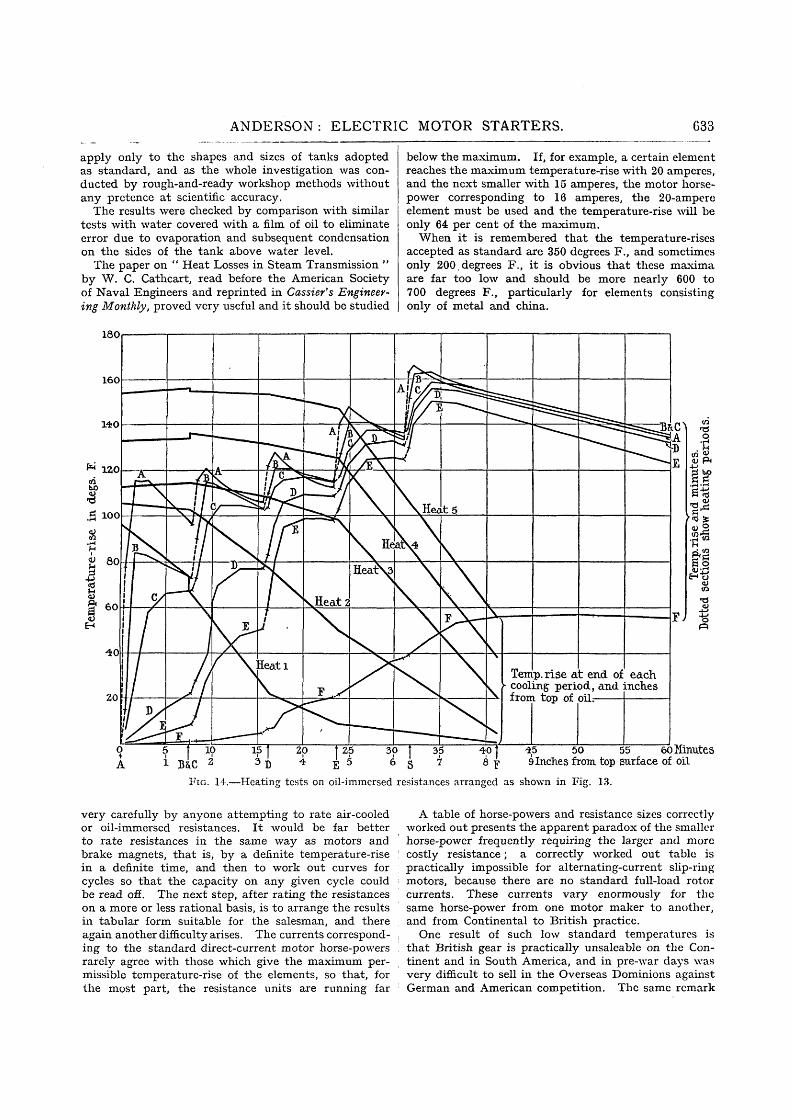
Fig. 13 shows a standard three-phase rotor starterwith three elements, i.e. one element per phase, anda series of brass pockets soldered into the side of thetank. A drop of mercury was placed in each pocketto give good contact with the thermometer which eachcontained; and Fig. 14 shows the results obtainedwith 6 100 watts per phase, 30 seconds " on " and 7jminutes " off," with 335 watts per square inch surfaceof wire. Full particulars are given of the test, butmany such tests must be made before a working theorycan be deduced.
An interesting point to note is the lag of the tempera-ture-rise after switching off. This is perhaps moreclearly shown in Fig. 15 which is drawn to comparethe results of an element wound with many turns ofthin wire, with those on one wound with a few turnsof thick wire.
An attempt to study exactly how the heat is trans-mitted from the wire to the oil near the wire and thencethrough the body of the oil, formed an interestinginvestigation. It was thought that a study of thebehaviour of water with coloured particles in suspensionwould be useful, but so many problems were introduceddue to air in solution and boiling that this study wasnot followed up.
One method of tracing the diffusion was by meansof little clouds of coloured ink, but the method gavelittle result because the clouds dissipated imperceptibly.
Pure cooling tests, as apart from diffusion, took along time ; it may seem easy to say that the heat lossis so much per square inch of surface, but questionsthat arise are : What is the cooling surface; what isthe effect of fins, vertical and horizontal; and arethere any correct proportions ?
Even so simple a thing as the determination of thespecific heat of the oil used offered difficulties, andwidely varying results were obtained according to themethod used. In addition, considerable care has tobe taken to obtain a reliable figure.
It would take up too much space to go into thequestion fully, particularly as the worked-out results
ANDERSON : ELECTRIC MOTOR STARTERS. 633
apply only to the shapes and sizes of tanks adoptedas standard, and as the whole investigation was con-ducted by rough-and-ready workshop methods withoutany pretence at scientific accuracy.
The results were checked by comparison with similartests with water covered with a film of oil to eliminateerror due to evaporation and subsequent condensationon the sides of the tank above water level.
The paper on " Heat Losses in Steam Transmission "by W. C. Cathcart, read before the American Societyof Naval Engineers and reprinted in Cassier's Engineer-ing Monthly, proved very useful and it should be studied
180
below the maximum. If, for example, a certain elementreaches the maximum temperature-rise with 20 amperes,and the next smaller with 15 amperes, the motor horse-power corresponding to 16 amperes, the 20-ampereelement must be used and the temperature-rise will beonly 64 per cent of the maximum.
When it is remembered that the temperature-risesaccepted as standard are 350 degrees F., and sometimesonly 200, degrees F., it is obvious that these maximaare far too low and should be more nearly 600 to700 degrees F., particularly for elements consistingonly of metal and china.
Temp, rise at end of each• cooling period, and inches
from top of oil:
50 55 60 Minutes9 Inches from top surface of oil
FIG. 14.—Heating tests on oil-immersed resistances arranged as shown in Fig. 13.
very carefully by anyone attempting to rate air-cooledor oil-immersed resistances. It would be far betterto rate resistances in the same way as motors andbrake magnets, that is, by a definite temperature-risein a definite time, and then to work out curves forcycles so that the capacity on any given cycle couldbe read off. The next step, after rating the resistanceson a more or less rational basis, is to arrange the resultsin tabular form suitable for the salesman, and thereagain another difficulty arises. The currents correspond-ing to the standard direct-current motor horse-powersrarely agree with those which give the maximum per-missible temperature-rise of the elements, so that, forthe most part, the resistance units are running far
A table of horse-powers and resistance sizes correctlyworked out presents the apparent paradox of the smallerhorse-power frequently requiring the larger and morecostly resistance; a correctly worked out table ispractically impossible for alternating-current slip-ringmotors, because there are no standard full-load rotorcurrents. These currents vary enormously for thesame horse-power from one motor maker to another,and from Continental to British practice.
One result of such low standard temperatures isthat British gear is practically unsaleable on the Con-tinent and in South America, and in pre-war days wasvery difficult to sell in the Overseas Dominions againstGerman and American competition. The same remark

634 ANDERSON: ELECTRIC MOTOR STARTERS.
applies to cable connections and switchgear generally.The waste of cable in connecting starters is sometimesgrotesque ; people study the I.E.E. Wiring Rules anduse those sections specified, irrespective of the timerating and normal working conditions. They seem toforget that these Rules are based on an extremelyconservative temperature-rise, considerably lower thanthat adopted by the French, Germans or Americans,and are for rubber-covered cables, covered up and runfor sufficient time on the rated load to produce thefinal steady temperature ; they seem to look only atthe figures for rubber and to ignore the tables for othermaterials. The figures are applied to short lengthsof cable on switchgear freely exposed to the air andwith considerable end cooling, and to short-ratedstarter connections without discrimination.
It is customary, on industrial switchgear, to orderpanels for a current in excess of the maximum it is
100
ho 80•3
% 60
4 0
5 20
0
//
//
1r
^* —— 6
3
20 60 80 100 120 WO 160 180Seconds
Fro. IT).—Heating tests on oil-immersed resistance elements.Tests 1 to 4 : 68-turn pot filled with 21 S.W.G. Heckaum.
(1) 3 520 watts — 67 watts/in.Surface.(2) 3 910 „ ^ 7 53) 9 200 „ •.* 175 „
(4) 20 769 „ •---* 410 „Tests 5 and « : 31-turn pot filled with 11 S.W.G. Hecknum.Test 5 : 11 500 watts =- 133 watts/in.8 surface.
,, 6: 20 000 ,, =•- 293 „ „: \ O T E : — Watts/in.1 surface not quite in ratio of total watts, owing to slight
differences in resistance. 10-second heating period.]
likely to be required to carry, and sometimes the nextlarger size is put in for mechanical reasons. Cablesections corresponding to the maximum capacity ona low basis rating are insisted upon.
An inspection of any standard gear by a good makerwill show what a very large amount of the total spaceis taken up by the cables, their sealing and clampingof armour and connecting up, and what a relativelysmall amount is taken up by the part doing useful work.
Standard lines of competitive industrial switchgearhave to be based on the average requirements of theaverage user and should not be expected to complywith exacting specifications.
The remarks on step-by-step starters apply generallyto both alternating and direct current, but startersfor alternating-current motors present certain problemspeculiar to themselves. The resistances are generally
connected in the rotors of slip-ring motors, but theymay be, and sometimes are, connected in both rotorand stator. They are connected in the stator ofsquirrel-cage motors.
Resistances in the rotor may be cut out of eachphase equally or unequally and may be either star- ordelta-connected ; the former is the more usual.
Balanced rotor currents and resistances cut out ofeach phase equally and practically simultaneouslymust be used when the maximum motor torque isdesired, and for speed regulation at or about full loadfor long periods.
Unbalanced rotor currents with resistances cut outof each phase unequally and at different times maybe used for starting at less than the maximum torque(the pull-out torque) or for speed regulation for shortperiods at or about full load, and for continuous speedregulation at, say, ^ load and less.
The amount of out-of-balance current determines thenumber of notches, but the standard formula for direct-current and balanced alternating-current starters isapplicable to alternating current unequally cut out,with certain reservations. •
The current-rush from notch to notch is of relativelysmall importance ; it is important, of course, but thebasis of the starter proportions must be the permissibleout-of-balance current.
There is no correct number of notches for alternating-current starters, but the greater the number the betterthe performance of the starter or controller.
It is far more difficult for the user to appreciate theeffect of increased notches and diminished out-of-balance rotor currents, because the rotor out-of-balancecurrent is not shown as being out of balance on thestator ammeters, whether the stator is star- or delta-connected.
The following table shows the stator and rotorammeter readings for various values of rotor resistance.
TABLE 4.
Rotor amperes in phase
104022
6383344-54453597077
Stator amperes in phase
263549
3912341222374265
3
3218
64/96(swinging)
36351937-53233251080
5-56-8
10-5
1414-5151616-318192223-5
6-27-5
10/13(swinging)
1515-81616-91718-82022-624-5
6-27-4
10/13(swinging)
14-5151516-516-718-82022-524-5
Stator : delta-connected.Rotor : star-connected.Rotor resistance : star-connected.Full-load stator current: 30 amperes.
ANDERSON: ELECTRIC MOTOR STARTERS. 635
It will be noticed that the rotor out-of-balance cur-rent may be so great that the motor is running aspractically a single-phase rotor, but the stator currentsare nearly balanced. This balancing transformer effectis so great that even the rotor current-rushes on changingfrom notch to notch are averaged and represented inthe stator by quite small swings.
The ammeters are marked as swinging in the thirdtest; this effect is very marked with a small rotorresistance on light load, and constitutes a serious troublewhen relays are connected in the rotor ; it is moreapparent with certain sizes of motors and certain makesthan with others, and in some cases the peaks are wellover 200 per cent full-load current even with the motordoing little mechanical work.
An exact knowledge of the rotor resistance is perhapsnot so essential with alternating-current as with direct-current motors, but it is very useful to have.
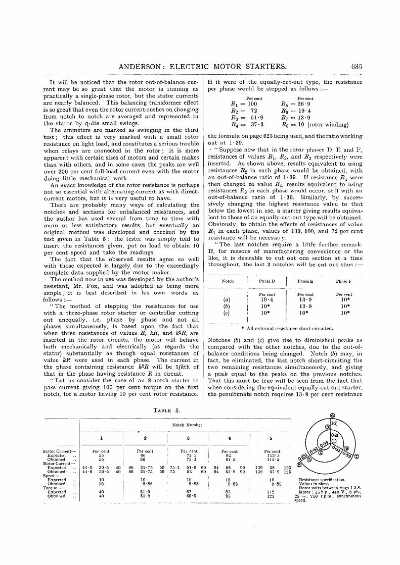
There are probably many ways of calculating thenotches and sections for unbalanced resistances, andthe author has used several from time to time withmore or less satisfactory results, but eventually anoriginal method was developed and checked by thetest given in Table 5 ; the tester was simply told toinsert the resistances given, put on load to obtain 10per cent speed and take the readings.
The fact that the observed results agree so wellwith those expected is largely due to the exceedinglycomplete data supplied by the motor maker.
The method now in use was developed by the author'sassistant, Mr. Fox, and was adopted as being moresimple; it is best described in his own words asfollows :—
" The method of stepping the resistances for usewith a three-phase rotor starter or controller cuttingout unequally, i.e. phase by phase and not allphases simultaneously, is based upon the fact thatwhen three resistances of values R, TcR, and h2R, areinserted in the rotor circuits, the motor will behaveboth mechanically and electrically (as regards thestator) substantially as though equal resistances ofvalue hR were used in each phase. The current inthe phase containing resistance Jfc2i2 will be 1/fcth ofthat in the phase having resistance R in circuit.
" Let us consider the case of an 8-notch starter topass current giving 100 per cent torque on the firstnotch, for a motor having 10 per cent rotor resistance.
If it were of the equally-cut-out type, the resistanceper phase would be stepped as follows :—
Per centi2x = 100R2 = 72i?3 = 51-9Ri = 37-3
Per cent#5 = 26-9RQ = 19-4R7 = 13-9i?8 = 10 (rotor winding)
the formula on page 623 being used, and the ratio workingout at 1-39.• " Suppose now that in the rotor phases D, E and F,
resistances of values Rit i?2> a n d R3 respectively were
inserted. As shown above, results equivalent to usingresistances R2 in each phase would be obtained, withan out-of-balance ratio of 1-39. If resistance RL werethen changed to value Rit results equivalent to usingresistances i?3 in each phase would occur, still with anout-of-balance ratio of 1 • 39. Similarly, by succes-sively changing the highest resistance value to thatbelow the lowest in use, a starter giving results equiva-lent to those of an equally-cut-out type will be obtained.Obviously, to obtain the effects of resistances of valueR1 in each phase, values of 139, 100, and 72 per centresistance will be necessary.
" The last notches require a little further remark.If, for reasons of manufacturing convenience or thelike, it is desirable to cut out one section at a timethroughout, the last 3 notches will be cut out thus :•—
Notch
(a)(b)(0)
Phase D
Per cent19-410*10*
Phase E
Per cent
13-913-910*
Phase F
Per rent10*10*10*
* All external resistance short-circuited.
Notches (b) and (c) give rise to diminished peaks ascompared with the other notches, due to the out-of-balance conditions being changed. Notch (b) may, infact, be eliminated, the last notch short-circuiting thetwo remaining resistances simultaneously, and givinga peak equal to the peaks on the previous notches.That this must be true will be seen from the fact thatwhen considering the equivalent equally-cut-out starter,the penultimate notch requires 13-9 per cent resistance
TABLE 5.
Stator Current—ExpectedObtained
Rotor Current-ExpectedObtained
Speed—ExpectedObtained
Torque—ExpectedObtained
1
Per cent5555
44-0 30-5 4044-6 30-5 40
1010
4040
2
Per cent6666
66 31•7566 31-75
109-85
51-951-9
Notch Number
3
Per cent73-573-1
59 , 75-1 51-9 6059 75 52 60
109-85
6768-5
4 i
Per cent9291-5
94 56 9994 55-2 99
109-85
1
8795
5
Per cent113-5l ] 2 - 5
132 58 125132 57-9 125
109-85
112121
Resistance specification.Values in ohms.Rotor volts between rinps 1 3 8.Motor: 25h.p., 440 V., 3 ph.,
25 ~ , 750 r.p.m., synchronousspeed.

636 ANDERSON: ELECTRIC MOTOR STARTERS.
per phase, the last notch, of course, short-circuitingthe rotor ; the former condition is equivalently obtainedon notch (a), the latter on notch (c). Therefore, toobtain a resistance specification for a rotor startercutting out resistance unequally (one section at a timethroughout) the " equivalent " resistance for the firstnotch, i.e. the resistance which would be used perphase if cutting out equally, must be determined.Next the ratio must be worked out from a formulasimilar to that on page 623, viz.
Ratio = n~2iequivalent resistance
rotor resistance per phase
and a specification drawn up as for the phase resistanceof an equally-cut-out type as shown in Fig. 16, notingthat the equivalent resistance is used on the secondstep [hence the term (n — 2) in the formula]. Thefirst step is given by
Equivalent resistance X ratio
" If the notch (b) above is dropped, as suggested, theformula becomes
equivalent resistance<rotor resistance per phase/
The values obtained are then allocated to the phasesin cyclic order, as shown in the figure, the last value
Ratio = .se/
winding. In consequence the dimensions become con-siderable ; the iron, surrounded as it is by the coil,is in a bad position for heat dissipation.
Another trouble, more apparent with infrequentstarting and non-reversing motors where the chokingcoil is short-circuited at full speed is that, if the chokingcoil is small, as it may be for infrequent service, thecopper voltage-drop is considerable and the current-rush on short-circuiting is very high if there is an appre-ciable load on the motor.
It would seem that a better result would be obtainedby the use of a true auto-transformer, with more orless laminated cores, which would supply current atlow voltages to a massive resistance element capableof being run at a high temperature, say 600° F., withoutrisk of damage to the windings ; the auto-transformercould be designed for any convenient loss, and therequired torque obtained by adjusting the resistance.
At standstill the choking coil is subjected to fullrotor pressure at line frequency ; at full-load speed thevoltage and frequency are those due to slip, say 3 percent, and on reversal of the stator at full speed thefrequency and voltage are double the normal values ;as the eddy-current losses are proportional to thesquare of the frequency and square of the induction,and the hysteresis losses to the l-6th or l-7th powerof the induction, a very interesting series of calculations
Notches%Resistance 139
PhasesNotches
D
100—I—
E
51-9 37-3 26-9 19-4
D E
2 4'
Notch. 8 is not essent ia l
F I G . 16.
13-9 10
8D&F
Short-circuited
9D^E&FShort-
circuited
representing the resistance per phase of the rotor.To prevent undue heating of one phase of the rotorwhen the controller is left standing on any notch, aratio of not more than 1-8 should be employed."
A type of rotor starter which presents quite anotherseries of problems is that frequently known as theeddy-current starter. It consists of a choking coilwound on a solid iron core, and the starting torque isdue mainly to the eddy-current and hysteresis lossesin the iron at standstill. The accelerating torqueduring speeding up is due partly to these losses andpartly to the I2R losses in the copper, the former pre-dominating at low speeds, and the latter becomingmore important as full speed is reached. It is a veryuseful form for reversing rolling mills, because onlya reversing switch is required ; a heavy torque is estab-lished on reversal of the stator which first retards themotor to standstill and then accelerates it in the oppositedirection.
If this cycle is repeated continuously, however, theiron heats up very much, in spite of the high (specificheat x weight) value of the iron core, and the per-missible temperature-rise is comparatively low, say150 degrees F., on account of the risk of scorching the
is opened up, and presents another problem to thestarter maker.
An entirely different series of problems has to beconsidered when the resistance is inserted in the statoror when star-delta or auto-transformer starters areused, because the motor is starting from short-circuitconditions and, if the subject is to be dealt with thor-oughly, it is necessary to have the performance curves,i.e. the torque/current, horse-power/current, slip/current,power factor/current, and efficiency/current curves fullyworked out from no-load full-speed, to standstill/short-circuit conditions, together with the stator and rotorwinding resistances.
At one time it was quite impossible to obtain thesedata, and a series of supposititious circle diagrams hadto be utilized ; even to-day the motor makers withone or two exceptions are so unwilling to supply thesedata that the suspicion arises that in many cases theydo not possess them.
The characteristics of starting conditions wherestator rheostatic, auto-transformer or star-delta startersare used, are light starting (initial) torques and almostany starting time.
The saw-tooth curves are no longer characteristic

ANDERSON: ELECTRIC MOTOR STARTERS. 637
and that shown in Fig. 17 is typical. It is drawn for10 000 ft.-lb. per b.h.p. stored energy, and the smallkick on cutting out the line resistance is not shown.The current curve is square-shouldered instead of saw-toothed, and the torque curve bears no resemblanceto the current curve.
An interesting series of curves are those for centri-fugal pump loads for which this class of starter is quitesuitable, but they are not shown here.
Fig. 18 has been worked out for various amounts ofline resistance and, if the load torque is known, a glanceat the curve shows how much current must be passed
95-5 per cent speed (4-5 per cent slip), and the currentwill rise at change-over to 285 per cent and fall to 120per cent; if all the resistance is now cut out the motorwill run up to 97 per cent speed (3 per cent slip),and the current will rise to 150 per cent and fall to100 per cent.
Results of calculations worked out from Figs. 17and 18 are conveniently recorded as shown in Fig. 19,the arrangement of which is due to Mr. Fox.
If the load torque during acceleration is constant at40 per cent, a glance shows that a current not lessthan 350 per cent must be passed on the first notch,
90 270
60
10 30
0 020 120 110
Seconds240 1:00
FIG. 17.—Rhcostatic stator starter. Line resistance passing about 250 per cent current. Drawn for a stored energy of10 000 ft.-lb./b.h.p. At 20 per cent friction load the average and R.M.S. currents are about 95 per cent of initialcurrent. Small kick on finally cutting out line resistance not shown.
on the first notch ; it shows how the motor torqueand current vary while running up to speed ; and ifthe load torque is laid off on the diagram as has beendone for centrifugal fan or pump loads, it can be seenat a glance how many notches the starter should have.
Take, for example, the fan or pump load startingat 10 per cent torque and rising to 100 per cent as thespeed rises.
A current of 150 per cent on the first notch will notstart it, but 250 per cent current will, and the speedwill run up to about 70 per cent (30 per cent slip) whilethe current will have fallen to 210 per cent; if thenext notch has a resistance which should pass 350 percent current at standstill, the motor will run up to
according to the accelerating time desired, but if 350per cent current is used the margin of motor torqueto overcome static friction will be small; if rotationdid start, the time would be 68 seconds for a load having5 000 ft.-lb. stored energy per b.h.p., and pro rata forother amounts.
If 400 per cent current is passed, the margin of motortorque will be ample because this point falls on thecross ; the time will be 38 seconds and if the motoris thrown direct on to line there will be a very largemargin of excess torque and the accelerating time willbe about 8 | seconds.
If the load is a centrifugal fan load running up to100 per cent torque, reference to the other curves shows

038 ANDERSON: ELECTRIC MOTOR STARTERS.
that it will not start with 250 per cent current; and thatwith 300 per cent current on the first notch and asuitable starter it can be made to run up in 79 secondswith 5 000 ft.-lb. per b.h.p. stored energy. 1 000 ft.-lb.would be a high figure, and 16 seconds more than anormal time.
There is an apparent discrepancy between thesefigures and those used when discussing Fig. 18 ; theexplanation is that the latter figure is drawn for astarter properly proportioned to give current-rushesequal to the initial current on changing from notch tonotch.
Intermediate curves should be drawn and the set
and the initial is 250 to 350 per cent, it must be badfor the motors and cause excessive heating and troubledue to repeated expansion and contraction. Yet speci-fications come along for auto-transformer starters witha 2-minute accelerating time once every 10 minutes,and on occasion even more frequently ; for such speci-fications the transformer becomes larger than it wouldbe if it were continuously rated.
Table 6 shows the torques obtained from auto-transformer taps ; a transformer was connected upusing equal and unequal taps on the three phases, withthe results shown.
If the friction torque is taken as 24 per cent, the
750 375
700 350
650 325
600 300
550 275
500 250
# 450 § 225
5 5d ̂ 00.3 2002 y
g 350 S 175
£ 300 £ 150250 125
200 100
150 75
100
50
0
50
25
-_
I
l—i
/ /
///
/
/
/
/
//ALA A sA
fife*wm ^=
^-Fanloadris
„—-
^-Fauioaa rising ~
~ -T- • —..
-
^ ^ :
—•
-
1 — — —
" " .
" —
1
,
-
-
- —
- —
- —
— • —
• * — - - .
• • • -
—
7
5
^ ^725'
3
ZJ
•
25%/
30%/
50%/
50%/
500%/150%/
35Oc
250'
ISO1}
a
O 5 10 15 20 25 30 35 -iO 45 50 55 60 65 70 75 80 85 90 95 100Per cent slip
FIG. 18.—Rheostatic stator starter. Torque and current curves with various amounts of resistance in line. Light linesrepresent driving torques for fan loads.
repeated for motors having, say, 400, 500 and 600 percent short-circuited current, and then the whole seriesshould be re-calculated for auto-transformers withvarious tap voltages.
The auto-transformer curves also serve for star-delta and series-parallel starters because these act likean auto-transformer with one tap and without thevoltage-drop in the transformer windings.
The starter maker has, then, a means of tacklingintelligently and quickly any starting problem.
It is common practice to use these starters on anymachine requiring low starting torque without specialattention to the accelerating time; if the averagecurrent over the period is 80 to 95 per cent of the initial,
observed accelerating times in column 4 correspond tothe torques in column 5. The latter correspond fairly tothe torques in column 6, which is based on the assumptionthat the unequal taps gave a mean torque and do notcorrespond to the torques in column 7, which is basedon the assumption that the effective torque is that ofthe lowest tap and that the higher taps on the otherphases have no effect.
The rating of rheostatic stator starters follows thegeneral lines already described, but new problems arisein rating the auto-transformers.
An inspection of Fig. 19 in conjunction with thestarting conditions given in Table 2 shows that a 30-second rating is ample for average conditions ; in fact,

ANDERSON: ELECTRIC MOTOR STARTERS. 639
the vast majority of auto-transformer jobs do notrequire more than 10 seconds per start.
Tests show that the only factor that matters is thetemperature-rise of the copper, i.e. the I2R losses, andthat the iron has no time to heat. For short periods,e.g. 10 to 30 seconds, the rating is based on the specificheat multiplied by the weight of copper ; the truecooling is very poor and an auto-transformer is par-ticularly unsuitable for continuous-cycle starting.
TABLE 6.*
Unequal Taps on Auto-transformer Starter.
Col. 1 Col. 2 Col. 3
Taps in phase
A B
0 5
0750-75060-750 7 50-75
0 5
0-50-60-60 60-750 7 5
0-5
0-50 50-60-60 50-75
Col. 4
Sees, torun to83 %speed
Does notstart
654-54-0 +30 -2-0 +
Col. 5 Col. 6 Col. 7
Torques inratio of
timestaking 24 %
friction
25
3334-83637-54251
Torques as j °p .̂g
sq^reof fXw^ttaps
25
33637-6364142 351
tap
25
253636362556-25
There is little advantage in oil immersion, becausethe oil cannot circulate freely round the windings.Even if it could there would be little effect at a tempera-ture-rise of 100 to 150 degrees F. ; the maximum in-crease in rating that can be traced to the oil is about10 per cent and the author neglects it in his calculations.
The chief advantage of the oil is that it excludesmoisture, prevents the cotton covering charring, andpermits the use of a fairly high temperature-rise, say150 degrees F., with perfect safety.
A point which requires consideration is the magnet-izing current; if the iron is cut down drastically thisgoes up and may become very important; the designerof an auto-transformer for starting purposes has todiscard many of his preconceived notions acquiredwhen dealing with transformers for continuous duty.One of these is the question of regulation, which isdetermined by the temperature-rise in the period.Apart from this it is of little consequence, because thefunction of an auto-transformer is to reduce the linecurrent and the pressure at the motor terminals, andit matters little whether this is due purely to trans-formation or not.
If there is a rather large drop in the windings it ismerely a question of using the next higher tap.
It is necessary to decide whether to rate for a definitetorque and time so that the higher taps necessarilymean shorter times, or to rate for constant time on
* Stator steady running current 43-4 per cent full load at fullspeed, equivalent to 28 per cent torque from characteristic curves.
It is known from previous tests that the torque rises with thespeed on this particular load, so that 24 per cent torque at 83 percent speed is approximately correct.
all taps so that the higher taps mean greater torqueand a correspondingly greater duty. Buyers are notat all clear as to what they want, and are apt to argueone way or the other according to circumstances.
This paper has given only an outline of the problemsconfronting the starter maker ; many important andinteresting matters are not even mentioned and othersare passed over with little notice, but if the paper leadsto a more general recognition that a starter is some-
2 1 0
5po%/ l3* notch|-5500>o/'ist notch-
20 40 60 80 100 120 140Per cent friction on load torque
100 ZOO 300 400 500 600 700Per cent current on first notch
160
800
FIG. 19.—Rheostatic stator starter curves, drawn for motorhaving 725 per cent short-circuit current. Calculatedfor 5 000 ft.-lb./b.h.p. stored energy.
Use of full-line curves.—Crosses show points which should not be exceededto allow of sufficient excess motor torque to overcome static friction. Forexample, constant load or friction torque during acceleration of 40 per ctnt.Cross on 400 per cent current curve corresponds, so sure to start; acceleratingtime 38 seconds for 5 000 ft.-lb./b.h.p. and pro rata for other amounts of storedenergy. Could use 350 per cent current first notch, but balance of excess torqueto overcome static friction very low ; accelerating time 68 seconds.
Use of dotlcd-line curves.—These are for fan loads. l:or example, if passing300 per cent current first notch, with load rising to 100 per cent, acceleratingtime is 78" 5 seconds with 5 000 ft.-lb./b.h.p. With load rising to 50 per cent,accelerating time is 50 seconds.
thing more than a bit of wire, a few contacts and ahandle, it will have served its purpose.
The author wishes to thank his assistant, Mr. H. C.Fox, for his work in preparing the diagrams and tablesand in correcting the manuscript, and for his helpfulcriticisms.
APPENDIX.
UNEQUALLY-CUT-OUT ROTOR RESISTANCES,OF METHOD.
PROOF
Field has sliown that the voltage-drop in three star-connected unequal resistances connected to a three-

640 ANDERSON: ELECTRIC MOTOR STARTERS: DISCUSSION.
phase supply may be determined graphically by draw-ing an equilateral triangle whose sides represent toscale the voltage between lines, and imagining thevalues of the conductance of each phase as a weight ateach corner of the triangle; the centre of gravity ofthe triangle is then the position of the neutral point,and lines drawn to each corner of the triangle from thispoint will represent in phase and magnitude the voltage-drop in the resistances concerned.
Fig. 20 shows such a construction for resistances inA, B, and C having the relative values R, Rk, and Rlc2.
FIG. 20.
Elementary geometry and trigonometry show thatthe following relations occur :—
AO
CO =
AC
&AC
+ 1)These give the voltage-drops across each resistance
as fractions of the line pressure.The currents will be :—
ACI n A '
InB,
InC,
- k + 1)
AC
k + 1)
The power per phase dissipated by the resistancewill be :—
In A,
InB,
InC,
Total,
AC2(&2 _ h _|_ i)
AC2
AC?kR
Dealing with relative values as hitherto, the lastequation may be rewritten thus :—
_ (linevolts)2~~ torque x slip
This has been called the " equivalent " resistance ofthe controller, since three equal resistances of this valuegive a similar effect to three unequal resistances ofvalues R, kR, and k2R. The magnitude of kR is usuallyrequired, as has been shown, for use in connection withthe first notch of a starter or controller, and in thiscase the slip, being unity, cancels out.
As shown in the paper, any movement round thecontroller towards the full-on position changes thevalue of the highest resistances to a value equal to(I/ratio) X the lowest, as each notch is reached, and,as the relationship R, Rk, Rk2 is preserved, the figurestill serves, the phase letters A, B, and C moving roundit cyclically as each change is made.
The foregoing method assumes that the rotor phasevolts and currents are in phase, and, although this isnot strictly true, the error involved by the assumptionis quite negligible in practical work.
SOUTH MIDLAND CENTRE, AT BIRMINGHAM, 15 MARCH, 1922.
Mr. W. Wilson: There is a tendency amongengineers to leave- out of consideration the statical portionof their equipment, and to direct an undue amount ofattention to the motor. It should, however, be realizedthat the great majority of the advances which are beingmade in electric drives to-day are due to improvementsin the design of the controlling apparatus. The motorhas apparently reached almost its final form, and it ischiefly on account of the important developments thatare taking place in connection with the design of startingand controlling gear that the application of the electricmotor is still extending rapidly. In addition to givingvaluable formulae and tables the author has directedattention to the difficulties under which the starterdesigner labours through the uncertainty of the data onwhich he has to base his calculations. The resistance of
the motor to be dealt with has been specially mentioned ;but, in addition, even greater uncertainty is introducedby variability in the speed of operating the starter,and extensive uncertainty also as to the nature of theload. The result of this usually is that very wideallowances are made in designing standard starters,which are therefore considerably larger, contain a greaternumber of steps, and are much more costly than shouldbe necessary. Dealing first with the speed of operation,I am glad that the author has shown so clearly that,in order to obtain the calculated results, the starterhandle has to be moved at a rate which increases ingeometrical progression from step to step. Onlylast year an important paper on the design of thisclass of apparatus showed the steps in the accelerationas a series of symmetrical saw-teeth, in which the