electric service requirements - kallinkallin.com/parkdrive/dwp code.pdf · ladwp electric service...
TRANSCRIPT

LADWP CITY OF LOS ANGELES DEPARTMENT OF WATER AND POWER
ELECTRIC SERVICE REQUIREMENTS
2010 EDITION
NOTICE
This manual is designed to provide you with the most current information on the Los Angeles Department of Water and Power’s (Department) service equipment and installation requirements. Every effort has been made to make this manual as complete and accurate as possible. These service requirements are subject to periodic revisions. If you have purchased a copy of these requirements from the Department, revisions and updates will be mailed to you at your current address of record. Please use the Change of Address Notification Form to notify the Department of any corrections or changes to your mailing address. Additional or replacement manuals may be ordered by mailing a check or money order for $50 to:
Los Angeles Department of Water and Power Attn: Mr. David L. Reusch 2633 Artesian Street Room 210 Los Angeles, California 90031-1805
For additional information or technical assistance regarding these requirements and for administrative inquiries regarding new manuals, replacement manuals or revisions, please contact Mr. D .L. Reusch at telephone number (213) 367-6182 or by e-mail at [email protected]. This manual may also be accessed on line at the Department’s website at http://www.LADWP.com.


LADWP ELECTRIC SERVICE REQUIREMENTS CITY OF LOS ANGELES DEPARTMENT OF WATER AND POWER
PAGE ii
CONTENTS Date 01-01-09
PAGE
SECTION 1 GENERAL INFORMATION . . . . . . . . . . . . . . . . . . . . . . . . . . . . . . . . . . . . . . . . 1-1
This section contains general service and policy information. SECTION 2 SERVICE AND METERING EQUIPMENT, 0-600 VOLTS . . . . . . . . . . . . . . . . . . 2-1
This section contains equipment requirements for wall-mounted metering equipment, service pedestals and underground supply terminating pull boxes.
SECTION 3 LOW-VOLTAGE SWITCHBOARDS, 0-600 VOLTS . . . . . . . . . . . . . . . . . . . . . . 3-1
This section contains equipment requirements for low-voltage switchboard metering equipment, underground supply terminating pull sections and busway service heads.
SECTION 4 MEDIUM-VOLTAGE SWITCHGEAR, 601-4800 VOLTS . . . . . . . . . . . . . . . . . . . 4-1
This section contains requirements for medium-voltage metering equipment and underground supply terminating pull sections.
SECTION 5 DESIGN AND INSTALLATION GUIDE FOR SERVICE AND METERING EQUIPMENT . . . . . . . . . . . . . . . . . . . . . . . . . . . . . . 5-1
This section contains specifications to assist customers in designing and installing low-voltage and medium-voltage services.
SECTION 6 DESIGN AND INSTALLATION GUIDE FOR ELECTRIC CONDUIT SYSTEMS ON PRIVATE PROPERTY . . . . . . . . . . . . . . . . . . . . . . . . 6-1
This section contains basic specifications to assist customers in designing and installing electric conduit systems on the customer’s property.
SECTION 7 DESIGN AND INSTALLATION GUIDE FOR OVERHEAD SERVICES, 0-600 VOLTS . . . . . . . . . . . . . . . . . . . . . . . . . . . . . . 7-1
This section contains specifications to assist customers in designing and installing low-voltage overhead electric services.
SECTION 8 DESIGN GUIDE FOR CUSTOMER-OWNED PARALLEL-GENERATING SYSTEMS . . . . . . . . . . . . . . . . . . . . . . . . . . . . . . . 8-1
This section contains specifications to assist customers in designing self-generating systems intended to operate in parallel with the Department’s electric distribution system.
SECTION 9 INDEX AND GLOSSARY . . . . . . . . . . . . . . . . . . . . . . . . . . . . . . . . . . . . . . . . . . 9-1
This section contains an index to assist customers in locating information in this manual, EUSERC/ESR acceptability table and a Glossary of common terms.


LADWP ELECTRIC SERVICE REQUIREMENTS CITY OF LOS ANGELES DEPARTMENT OF WATER AND POWER
PAGE 1-1
GENERAL INFORMATION Date 01-01-07
CONTENTS
PAGEA. Office Locations and Telephone Assistance 1-4
1. Engineering Offices . . . . . . . . . . . . . . . . . . . . . . . . . . . . . . . . . . . . . . . . . . . . . . . . . . . . . . . . . . . . . . 1-42. Service Planning Area Boundary Map . . . . . . . . . . . . . . . . . . . . . . . . . . . . . . . . . . . . . . . . . . . . . . . . 1-53. Customer Service Branch Offices . . . . . . . . . . . . . . . . . . . . . . . . . . . . . . . . . . . . . . . . . . . . . . . . . . 1-64. Telephone Numbers . . . . . . . . . . . . . . . . . . . . . . . . . . . . . . . . . . . . . . . . . . . . . . . . . . . . . . . . . . . . . 1-6
B. Planning Electric Services . . . . . . . . . . . . . . . . . . . . . . . . . . . . . . . . . . . . . . . . . . . . . . . . . . . . . . . . . . . 1-8
1. Initial Contact . . . . . . . . . . . . . . . . . . . . . . . . . . . . . . . . . . . . . . . . . . . . . . . . . . . . . . . . . . . . . . . . . . 1-82. Plan Submittals . . . . . . . . . . . . . . . . . . . . . . . . . . . . . . . . . . . . . . . . . . . . . . . . . . . . . . . . . . . . . . . . . 1-83. Service Confirmations and Facilities Requirements . . . . . . . . . . . . . . . . . . . . . . . . . . . . . . . . . . . . 1-84. Applications for Service . . . . . . . . . . . . . . . . . . . . . . . . . . . . . . . . . . . . . . . . . . . . . . . . . . . . . . . . . . 1-85. Fees and Charges . . . . . . . . . . . . . . . . . . . . . . . . . . . . . . . . . . . . . . . . . . . . . . . . . . . . . . . . . . . . . . . 1-86. Permits and Inspections . . . . . . . . . . . . . . . . . . . . . . . . . . . . . . . . . . . . . . . . . . . . . . . . . . . . . . . . . . 1-97. Scheduling and Construction . . . . . . . . . . . . . . . . . . . . . . . . . . . . . . . . . . . . . . . . . . . . . . . . . . . . . . 1-98. Project Status and Scheduling Information . . . . . . . . . . . . . . . . . . . . . . . . . . . . . . . . . . . . . . . . . . . . 1-99. Time-Lines for Installation of Electric Services . . . . . . . . . . . . . . . . . . . . . . . . . . . . . . . . . . . . . . . . 1-10
a. Underground Residential Services . . . . . . . . . . . . . . . . . . . . . . . . . . . . . . . . . . . . . . . . . . . . . . 1-10b. Overhead Residential Services . . . . . . . . . . . . . . . . . . . . . . . . . . . . . . . . . . . . . . . . . . . . . . . . . 1-11c. Underground Commercial, Light Industrial, and Large Residential Services . . . . . . . . . . . . . . 1-12d. Overhead Commercial, Light Industrial, and large Residential Services . . . . . . . . . . . . . . . . . 1-13e. Services Supplied from Customer Station Installations . . . . . . . . . . . . . . . . . . . . . . . . . . . . . . . 1-14f. Temporary Services . . . . . . . . . . . . . . . . . . . . . . . . . . . . . . . . . . . . . . . . . . . . . . . . . . . . . . . . . . 1-15
(1) Temporary Services, Overhead . . . . . . . . . . . . . . . . . . . . . . . . . . . . . . . . . . . . . . . . . . . . . 1-15(2) Temporary Services, Underground . . . . . . . . . . . . . . . . . . . . . . . . . . . . . . . . . . . . . . . . . . 1-16
g. Parallel-Generation Installations . . . . . . . . . . . . . . . . . . . . . . . . . . . . . . . . . . . . . . . . . . . . . . . . . 1-17
Service Planning Information Form . . . . . . . . . . . . . . . . . . . . . . . . . . . . . . . . . . . . . . . . . . . . . . . . . . . . . . . 1-19
C. Electric Load . . . . . . . . . . . . . . . . . . . . . . . . . . . . . . . . . . . . . . . . . . . . . . . . . . . . . . . . . . . . . . . . . . . . . . 1-21
1. General . . . . . . . . . . . . . . . . . . . . . . . . . . . . . . . . . . . . . . . . . . . . . . . . . . . . . . . . . . . . . . . . . . . . . . 1-21 2. Changes in Connected Load . . . . . . . . . . . . . . . . . . . . . . . . . . . . . . . . . . . . . . . . . . . . . . . . . . . . . . 1-21 3. Insufficient Load . . . . . . . . . . . . . . . . . . . . . . . . . . . . . . . . . . . . . . . . . . . . . . . . . . . . . . . . . . . . . . . 1-21 4. Load Characteristics Affecting Other Customers . . . . . . . . . . . . . . . . . . . . . . . . . . . . . . . . . . . . . . 1-21 5. Single-Phase Motors . . . . . . . . . . . . . . . . . . . . . . . . . . . . . . . . . . . . . . . . . . . . . . . . . . . . . . . . . . . . 1-21 6. Three-Phase Motors . . . . . . . . . . . . . . . . . . . . . . . . . . . . . . . . . . . . . . . . . . . . . . . . . . . . . . . . . . . . 1-21 7. Lighting . . . . . . . . . . . . . . . . . . . . . . . . . . . . . . . . . . . . . . . . . . . . . . . . . . . . . . . . . . . . . . . . . . . . . . 1-22 8. Heating, Cooking, and Miscellaneous Loads . . . . . . . . . . . . . . . . . . . . . . . . . . . . . . . . . . . . . . . . . 1-22 9. X-Rays Units over 5 Kva . . . . . . . . . . . . . . . . . . . . . . . . . . . . . . . . . . . . . . . . . . . . . . . . . . . . . . . . . 1-2210. Welders . . . . . . . . . . . . . . . . . . . . . . . . . . . . . . . . . . . . . . . . . . . . . . . . . . . . . . . . . . . . . . . . . . . . . . 1-2211. Special Equipment . . . . . . . . . . . . . . . . . . . . . . . . . . . . . . . . . . . . . . . . . . . . . . . . . . . . . . . . . . . . . 1-23
D. Inspections . . . . . . . . . . . . . . . . . . . . . . . . . . . . . . . . . . . . . . . . . . . . . . . . . . . . . . . . . . . . . . . . . . . . . . . . 1-24
1. General . . . . . . . . . . . . . . . . . . . . . . . . . . . . . . . . . . . . . . . . . . . . . . . . . . . . . . . . . .. . . . . . . . . . . . . 1-242. Scheduling Inspections . . . . . . . . . . . . . . . . . . . . . . . . . . . . . . . . . . . . . . . . . . . . . . . . . . . . . . . . . . . 1-243. Special Inspections . . . . . . . . . . . . . . . . . . . . . . . . . . . . . . . . . . . . . . . . . . . . . . . . . . . . . . . . . . . . . . 1-24
E. Service Voltages . . . . . . . . . . . . . . . . . . . . . . . . . . . . . . . . . . . . . . . . . . . . . . . . . . . . . . . . . . . . . . . . . . . . 1-25
1. Character of Service . . . . . . . . . . . . . . . . . . . . . . . . . . . . . . . . . . . . . . . . . . . . . . . . . . . . . . . . . . . 1-252. Service Supply Voltages . . . . . . . . . . . . . . . . . . . . . . . . . . . . . . . . . . . . . . . . . . . . . . . . . . . . . . . . . . 1-253. Acceptable Voltage Ranges . . . . . . . . . . . . . . . . . . . . . . . . . . . . . . . . . . . . . . . . . . . . . . . . . . . . . . . 1-26

PAGE 1-2 ELECTRIC SERVICE REQUIREMENTS CITY OF LOS ANGELES DEPARTMENT OF WATER AND POWER LADWP
Date: 01-01-08 GENERAL INFORMATION
CONTENTS (Cont.)
PAGE
F. Classes of Service . . . . . . . . . . . . . . . . . . . . . . . . . . . . . . . . . . . . . . . . . . . . . . . . . . . . . . . . . . . . . . . . . . 1-27
G. Short-Circuit Current and Over-Current Protection . . . . . . . . . . . . . . . . . . . . . . . . . . . . . . . . . . . . . . . 1-28
H. Temporary Services . . . . . . . . . . . . . . . . . . . . . . . . . . . . . . . . . . . . . . . . . . . . . . . . . . . . . . . . . . . . . . . . 1-29
1. Application Fees and Charges . . . . . . . . . . . . . . . . . . . . . . . . . . . . . . . . . . . . . . . . . . . . . . . . . . . . . . 1-292. Permits and Approvals . . . . . . . . . . . . . . . . . . . . . . . . . . . . . . . . . . . . . . . . . . . . . . . . . . . . . . . . 1-293. Time Limitations . . . . . . . . . . . . . . . . . . . . . . . . . . . . . . . . . . . . . . . . . . . . . . . . . . . . . . . . . . . . . . . . 1-294. Removal of Service . . . . . . . . . . . . . . . . . . . . . . . . . . . . . . . . . . . . . . . . . . . . . . . . . . . . . . . . . . . . . . 1-295. Installation Requirements . . . . . . . . . . . . . . . . . . . . . . . . . . . . . . . . . . . . . . . . . . . . . . . . . . . . . . . . . 1-30
I. Flat Connected Services . . . . . . . . . . . . . . . . . . . . . . . . . . . . . . . . . . . . . . . . . . . . . . . . . . . . . . . . . . . . . 1-31
1. General . . . . . . . . . . . . . . . . . . . . . . . . . . . . . . . . . . . . . . . . . . . . . . . . . . . . . . . . . . . . . . . . . . . . . . . 1-312. Emergency Flat Services . . . . . . . . . . . . . . . . . . . . . . . . . . . . . . . . . . . . . . . . . . . . . . . . . . . . . . . . . 1-313. Building or Service Alterations . . . . . . . . . . . . . . . . . . . . . . . . . . . . . . . . . . . . . . . . . . . . . . . . . . . . . . 1-31
J. Customer-Owned Generators . . . . . . . . . . . . . . . . . . . . . . . . . . . . . . . . . . . . . . . . . . . . . . . . . . . . . . . . . 1-32
A. Emergency or Stand-by Generators . . . . . . . . . . . . . . . . . . . . . . . . . . . . . . . . . . . . . . . . . . . . . . . . . 1-32B. Customer-owned Parallel Generation Systems . . . . . . . . . . . . . . . . . . . . . . . . . . . . . . . . . . . . . . . . 1-32
K. Transformer Installations on the Customer’s Premises . . . . . . . . . . . . . . . . . . . . . . . . . . . . . . . . . . . . . 1-34
1. General . . . . . . . . . . . . . . . . . . . . . . . . . . . . . . . . . . . . . . . . . . . . . . . . . . . . . . . . . . . . . . . . . . . . . . . 1-34
2. Transformer Installations . . . . . . . . . . . . . . . . . . . . . . . . . . . . . . . . . . . . . . . . . . . . . . . . . . . . . . . . . . 1-34
a. Pole-Mounted Transformer Installations . . . . . . . . . . . . . . . . . . . . . . . . . . . . . . . . . . . . . . . . . . 1-34b. Padmount Transformer Installations . . . . . . . . . . . . . . . . . . . . . . . . . . . . . . . . . . . . . . . . . . . . . 1-35c. Underground Vault Transformer Installations . . . . . . . . . . . . . . . . . . . . . . . . . . . . . . . . . . . . . . . 1-35d. Outdoor Transformer Installations . . . . . . . . . . . . . . . . . . . . . . . . . . . . . . . . . . . . . . . . . . . . . . . 1-35e. Indoor Transformer Installations . . . . . . . . . . . . . . . . . . . . . . . . . . . . . . . . . . . . . . . . . . . . . . . . . 1-35
3. Standard Installations . . . . . . . . . . . . . . . . . . . . . . . . . . . . . . . . . . . . . . . . . . . . . . . . . . . . . . . . . . . 1-36
4. Charges for Nonstandard Installations . . . . . . . . . . . . . . . . . . . . . . . . . . . . . . . . . . . . . . . . . . . . . 1-36
5. Access and Clearances . . . . . . . . . . . . . . . . . . . . . . . . . . . . . . . . . . . . . . . . . . . . . . . . . . . . . . . . . . 1-36
6. Customer Stations . . . . . . . . . . . . . . . . . . . . . . . . . . . . . . . . . . . . . . . . . . . . . . . . . . . . . . . . . . . . . . . 1-37
a. General . . . . . . . . . . . . . . . . . . . . . . . . . . . . . . . . . . . . . . . . . . . . . . . . . . . . . . . . . . . . . . . . . . . 1-37b. Redesigns and Cancellations . . . . . . . . . . . . . . . . . . . . . . . . . . . . . . . . . . . . . . . . . . . . . . . . . . 1-37c. Insufficient Load . . . . . . . . . . . . . . . . . . . . . . . . . . . . . . . . . . . . . . . . . . . . . . . . . . . . . . . . . . . . . 1-37d. Scheduled Maintenance/Standby Generators . . . . . . . . . . . . . . . . . . . . . . . . . . . . . . . . . . . . . . 1-38

LADWP ELECTRIC SERVICE REQUIREMENTS CITY OF LOS ANGELES DEPARTMENT OF WATER AND POWER
PAGE 1-3
GENERAL INFORMATION Date 02-01-03
THIS PAGE LEFT INTENTIONALLY BLANK

PAGE 1-4 ELECTRIC SERVICE REQUIREMENTS CITY OF LOS ANGELES DEPARTMENT OF WATER AND POWER LADWP
Date: 01-01-10 GENERAL INFORMATION
A. OFFICE LOCATIONS AND TELEPHONE ASSISTANCE
1. ENGINEERING OFFICES
a. VALLEY SERVICE PLANNING OFFICE (see Area Boundary Map) 7501 Tyrone Avenue - located north of Covello Street (TG 532-A4) Van Nuys, CA 91405
Tel (818) 771-4100 FAX (818) 771-4066
b. METROPOLITAN SERVICE PLANNING OFFICE (see Area Boundary Map)
2633 Artesian Street - located at Avenue 26 between Lacy St and Humboldt St (TG 594-J7) Room 210 Los Angeles, CA 90031
Tel (213) 367-6000 FAX (213) 367-6027
c. CUSTOMER STATION DESIGN GROUP: Serves projects throughout the Department's service area
including the Owens Valley area. 2633 Artesian Street - located at Avenue 26 between Lacy St and Humboldt St (TG 594-J7) Room 270 Los Angeles, CA 90031
Tel (213) 367-8019 or -8078 FAX (213) 367-8099
d. CABLE TELEVISION SERVICE UNIT: Serves CATV and cellular telephone projects throughout the
Department's service area except the Owens Valley area. 111 No. Hope Street - located at the corner of Hope St and First St (TG 634-F3) Room 869 Los Angeles, CA 90012
Tel (213) 367-4173 FAX (213) 367-3680

LADWP ELECTRIC SERVICE REQUIREMENTS CITY OF LOS ANGELES DEPARTMENT OF WATER AND POWER
PAGE 1-5
GENERAL INFORMATION Date 01-01-09
A. OFFICE LOCATIONS AND TELEPHONE ASSISTANCE (Cont.)
2. SERVICE PLANNING AREA BOUNDARY MAP (For service planning office addresses and telephone numbers, see page 1-4)
Areas served by Southern California Edison Company: 1. San Fernando 2. Beverly Hills and West Hollywood 3. Veterans Administration 4. Marina Del Rey 5. Universal Studios Boundary line between Metropolitan and Valley service planning offices: Valley Service Planning Office
Responsible for projects addressed on Mulholland Drive and on the west side of the Hollywood Freeway between Mulholland Drive and Barham Boulevard. Metropolitan Service Planning Office
Responsible for projects addressed on Barham Boulevard and on the east side of the Hollywood Freeway between Mulholland Drive and Barham Boulevard.

PAGE 1-6 ELECTRIC SERVICE REQUIREMENTS CITY OF LOS ANGELES DEPARTMENT OF WATER AND POWER LADWP
Date: 01-01-06 GENERAL INFORMATION
A. OFFICE LOCATIONS AND TELEPHONE ASSISTANCE (Cont.)
3. CUSTOMER SERVICE BRANCH OFFICES a. METROPOLITAN AND WEST LOS ANGELES AREA OFFICES:
Branch Office Address Main Office (Lobby) 111 N. Hope St. (corner of First Street and Hope Street)
Boyle Heights 919 S. Soto St., Suite 10 (south of Whittier Blvd)
Central 4619 S. Central Ave. (47th Street and Central Avenue)
Crenshaw/Baldwin Hills 4030 Crenshaw Blvd. (Crenshaw Blvd and Martin L. King Blvd)
Hollywood 1613 Cahuenga Blvd. (between Hollywood & Selma)
Lincoln Heights 2223 N. Broadway (North Broadway and Avenue 24)
Slauson-Vermont 5928 S. Vermont Ave. (one block south of Slauson Ave)
Watts 1686 E. 103rd St. (103rd St and Graham Ave)
West Los Angeles 1394 S. Sepulveda Blvd (between Wilshire Blvd and Santa Monica Blvd) b. SAN FERNANDO VALLEY OFFICES:
Branch Office Address Canoga Park 7229 Winnetka Ave. (Winnetka Ave and Sherman Way)
Mission Hills 11100 Sepulveda Blvd., Suite 3 (at San Fernando Mission Blvd)
Van Nuys 6550 Van Nuys Blvd. (between Haynes St and Kittridge St) c. HARBOR AREA OFFICES:
Branch Office Address San Pedro 535 W. 9th St. (between Pacific Ave and Gaffey St)
Wilmington 931 N. Avalon Blvd. (between Anaheim St and Pacific Coast Hwy) Note: For additional payment centers, visit the Department’s website at LADWP.com
4. TELEPHONE NUMBERS
a. For SPEECH AND HEARING IMPAIRED/TTY, call . . . . . . . . . . . . . . . . . . . . . . . . . . (800) 432-7397 b. To make APPLICATIONS FOR ELECTRIC SERVICE, call
a. Metropolitan Los Angeles . . . . . . . . . . . . . . . . . . . . . . . . . . . . . . . . . . . . . . . (213) 481-5411 b. All other areas . . . . . . . . . . . . . . . . . . . . . . . . . . . . . . . . . . . . . . . . . . . . . . . . (800) 342-5397 c. For information concerning INTERCONNECTED GENERATION INSTALLATIONS,
call . . . . . . . . . . . . . . . . . . . . . . . . . . . . . . . . . . . . . . . . . . . . . . . . . . . . . . . . . . . . . . .
(213) 367-3413 d. For information concerning ENERGY CONSERVATION, EFFICIENCY PROGRAMS and DEMAND-SIDE MANAGEMENT PROGRAMS call . . . . . . . . . . . . . (800) 827-5397

LADWP ELECTRIC SERVICE REQUIREMENTS CITY OF LOS ANGELES DEPARTMENT OF WATER AND POWER
PAGE 1-7
GENERAL INFORMATION Date 01-01-09
A. OFFICE LOCATIONS AND TELEPHONE ASSISTANCE (Cont.)
4. TELEPHONE NUMBERS (Cont.)
e. For information concerning ELECTRIC RATES, call . . . . . . . . . . . . . . . . . . . . . . . . (213) 367-0329 f. For information concerning ELECTRIC AND MAGNETIC FIELDS (EMF), call . . . . . . (213) 367-2616 g. For information regarding POWER QUALITY, call . . . . . . . . . . . . . . . . . . . . . . . . . . (213) 367-6080 h. For information regarding CONDUIT AND SUBSTRUCTURE LOCATION AND
MARKING, call Underground Service Alert (Dig Alert) at:
(1) For Southern California areas. . . . . . . . . . . . . . . . . . . . . . . . . . . . . . . . . . . . . . (800) 227-2600 (2) National one-call number . . . . . . . . . . . . . . . . . . . . . . . . . . . . . . . . . . . . . . . . . 8-1-1 h. Customer Service 24 Hour Phone Numbers: To report ELECTRIC OUTAGES,
DOWNED POWER LINES or other ELECTRIC HAZARDS, call:
(1) Local calls . . . . . . . . . . . . . . . . . . . . . . . . . . . . . . . . . . . . . . . . . . . . . . . . . . . . . (818) 342-5397 (2) Toll free . . . . . . . . . . . . . . . . . . . . . . . . . . . . . . . . . . . . . . . . . . . . . . . . . . . . . . . (800) 342-5397

PAGE 1-8 ELECTRIC SERVICE REQUIREMENTS CITY OF LOS ANGELES DEPARTMENT OF WATER AND POWER LADWP
Date: 01-01-09 GENERAL INFORMATION
B. PLANNING ELECTRIC SERVICES
1. INITIAL CONTACT
When considering the design of electrical facilities for a residential, commercial, or industrial premises, customers should contact the Department service planning office in the area where service is to be supplied as soon as possible so that: a. The Department's service planning staff can work with the customer to establish a serving voltage and
an acceptable meter and service location. b. Customers may avoid unnecessary expenses and delays in service caused by assuming the type of
service the Department will provide 2. PLAN SUBMITTALS
At the time of initial contact with a Department engineering office, please provide the following items: a. A completed Service Planning Information sheet - see page 1-19 for master copy. b. Electrical plans including load schedules, single-line diagrams, and equipment elevation drawings. c. Plot, grading, elevation, and site improvement plans. d. Any additional information requested by the service planner needed to assist the Department in
finalizing the customer’s plans. 3. SERVICE CONFIRMATIONS AND FACILITIES REQUIREMENTS
a. For projects to be served underground, the Department will provide a construction drawing or other
documentation specifying the facilities that the customer must install on the customer’s premises to accommodate the Department’s transformers, cables and any other equipment needed to supply the customer’s load.
b. For projects to be served overhead, the Department will provide a written confirmation of the serving
pole and it’s location. The customer is responsible for designing and building the service entrance and point of attachment facilities to meet the Department’s overhead service requirements. See Section 7 for the applicable design information.
4. APPLICATIONS FOR SERVICE
a. Customers must contact a Customer Service Branch Office to make application for electric service.
This should be done at the time of initial contact with an engineering office, or shortly after, to avoid delays in establishing service.
b. For locations and telephone numbers of Department engineering offices, see page 1-4.
5. FEES AND CHARGES
Customers must make payment in full for all fees and charges assessed by the Department before construction will be started or service will be established. Such fees and charges include but are not limited to service application fees, charges for temporary services, charges for construction or relocation of Department facilities, charges for line extensions or excess conductor allowances as specified in the Rules, charges for interconnection of customer-owned generation facilities and charges for nonstandard installations.

LADWP ELECTRIC SERVICE REQUIREMENTS CITY OF LOS ANGELES DEPARTMENT OF WATER AND POWER
PAGE 1-9
GENERAL INFORMATION Date 01-01-07
B. PLANNING ELECTRIC SERVICES (Cont.)
6. PERMITS AND INSPECTIONS
a. The Department will energize a customer's electric service only after the installation has been
inspected and cleared by both the Department and the permitting agency. b. Normally the following steps must be completed to establish electric service:
(1) An electrical permit must be obtained by the customer from the permitting agency. (2) All site electrical wiring must be completed and inspected by the permitting agency and the final
electrical release cleared to the Department (notice is generally made by teletype or letter).
Note: It may take several days after the final permitting agency inspection for the Department to be notified.
(3) All facilities specified by the Department must be inspected by the Department and all corrections
must be completed and approved. See page 1-24 for additional information.
7. SCHEDULING AND CONSTRUCTION a. When the required inspections have been completed and all fees and charges are paid in full, a
"release" will be sent to the appropriate Department service center for scheduling and construction. b. Installation of facilities by the Department will normally be scheduled during regular working hours.
However, customers may request the Department to install facilities during premium (overtime) hours for the convenience of the customer. Requests for premium time installations may be made by contacting the appropriate engineering office. Customers are required to reimburse the Department for all premium time charges.
c. The Department will make a reasonable effort to complete service installations as quickly as possible.
However, the time required to complete an installation will vary according to the complexity of the service and the number of services already scheduled or under construction.
d. The following timelines are provided to assist customers in planning and scheduling projects for:
(1) Underground residential services, see page 1-10. (2) Overhead residential services, see page 1-11. (3) Underground commercial, light industrial, and large residential services, see page 1-12. (4) Overhead commercial, light industrial, and large residential services, see page 1-13. (5) Customer Station installations (projects involving the Customer Station Design group), see
page 1-14. (6) Temporary Services, see pages 1-15. (7) Parallel-generation installations, see pages 1-17.
8. PROJECT STATUS AND SCHEDULING INFORMATION Customers may track the progress of new electric service installations and upgrades by address by visiting the Power System Work Request Information System page on the Department’s website at http://wmisweb.ladwp.com/powerwmis/.

PAGE 1-10 ELECTRIC SERVICE REQUIREMENTS CITY OF LOS ANGELES DEPARTMENT OF WATER AND POWER LADWP
Date: 01-01-07 GENERAL INFORMATION
B. PLANNING ELECTRIC SERVICES (Cont.)
9. TYPICAL TIME-LINES FOR INSTALLATION OF ELECTRIC SERVICES
a. UNDERGROUND RESIDENTIAL SERVICES
To expedite the installation of single-family residential electric services supplied from underground facilities, the Department recommends that work be scheduled in the following sequence: • Customer's building design and construction activities • Customer submits request for electric service (1) 4-6 weeks • Department provides customer with requirements for electric service • Customer installs on-site conduit and/or substructures (2) • Department inspects and releases on-site conduit and/or substructures 3-5 weeks • Department installs cables, transformers and other equipment in conduits and/or substructures • Customer completes electrical installation • Inspection and approval by permitting agency • Final Department inspection and release of service and metering equipment 5-10 days • Department energizes service and sets meter (3)
Customer Controlled Department Controlled (1) Includes complete set of site and electrical plans required to evaluate and design service. (2) This work must be completed 3 to 5 weeks prior to the completion of the customer's building construction to
allow the Department sufficient time to install the required cables and transformers. This will enable the Department to provide electric service in a matter of days after the Department receives the final release from the permitting agency, assuming the service application has been submitted and any required fees or deposits have been paid.
(3) The Department will make a reasonable effort to complete service installations as quickly as possible.
However, the time required to complete an installation will vary according to the complexity of the service and the number of services already scheduled or under construction.

LADWP ELECTRIC SERVICE REQUIREMENTS CITY OF LOS ANGELES DEPARTMENT OF WATER AND POWER
PAGE 1-11
GENERAL INFORMATION Date 01-01-05
B. PLANNING ELECTRIC SERVICES (Cont.)
b. OVERHEAD RESIDENTIAL SERVICES
To expedite the installation of single-family residential electric services supplied from overhead facilities, the Department recommends that work be scheduled in the following sequence: • Customer's building design and construction activities • Customer submits request for electric service (1) 2-4 weeks • Department provides customer with requirements for electric service • Customer installs service and metering equipment 2-4 weeks • Department installs off-site conductors, transformers and other facilities • Inspection and approval by Permitting Agency • Final Department inspection and release of service and metering equipment (3) 3-5 days • Department energizes service and sets meter (2)
Customer Controlled Department Controlled (1) Includes complete set of site and electrical plans required to evaluate and design service. (2) The Department will make a reasonable effort to complete service installations as quickly as possible.
However, the time required to complete an installation will vary according to the complexity of the service and the number of services already scheduled or under construction.
(3) For services rated up to 200 amperes, the Los Angeles Department of Building and Safety inspectors will
provide the final inspection for the Department.

PAGE 1-12 ELECTRIC SERVICE REQUIREMENTS CITY OF LOS ANGELES DEPARTMENT OF WATER AND POWER LADWP
Date: 01-01-05 GENERAL INFORMATION
B. PLANNING ELECTRIC SERVICES (Cont.)
c. UNDERGROUND COMMERCIAL, LIGHT INDUSTRIAL AND LARGE RESIDENTIAL SERVICES
To expedite the installation of commercial, light industrial, and large residential electric services supplied from underground facilities, the Department recommends that work be scheduled in the following sequence: • Customer's building design and construction activities • Customer submits request for electric service (1) 6-8 weeks • Department provides customer with requirements for electric service • Customer installs on-site conduit and/or substructures (2) • Department inspects and releases on-site conduit and/or substructures 3-5 weeks • Department installs cables, transformers and other equipment in conduits and/or substructures • Customer completes electrical installation • Inspection and approval by permitting agency • Final Department inspection and release of service and metering equipment 5-10 days • Department energizes service and sets Meter (3)
Customer Controlled Department Controlled
(1) Includes complete set of site and electrical plans required to evaluate and design service. (2) This work must be completed 3 to 5 weeks prior to the completion of the customer's building construction to
allow the Department sufficient time to install the required cables and transformers. This will enable the Department to provide electric service in a matter of days after the Department receives the final release from the permitting agency, assuming the service application has been submitted and any required fees or deposits have been paid.
(3) The Department will make a reasonable effort to complete service installations as quickly as possible.
However, the time required to complete an installation will vary according to the complexity of the service and the number of services already scheduled or under construction.
LADWP ELECTRIC SERVICE REQUIREMENTS CITY OF LOS ANGELES DEPARTMENT OF WATER AND POWER
PAGE 1-13
GENERAL INFORMATION Date 01-01-05
B. PLANNING ELECTRIC SERVICES (Cont.)
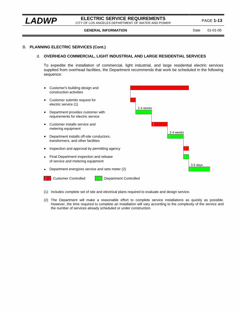
d. OVERHEAD COMMERCIAL, LIGHT INDUSTRIAL AND LARGE RESIDENTIAL SERVICES
To expedite the installation of commercial, light industrial, and large residential electric services supplied from overhead facilities, the Department recommends that work be scheduled in the following sequence: • Customer's building design and construction activities • Customer submits request for electric service (1) 2-4 weeks • Department provides customer with requirements for electric service • Customer installs service and metering equipment 2-4 weeks • Department installs off-site conductors, transformers, and other facilities • Inspection and approval by permitting agency • Final Department inspection and release of service and metering equipment 3-5 days • Department energizes service and sets meter (2)
Customer Controlled Department Controlled (1) Includes complete set of site and electrical plans required to evaluate and design service. (2) The Department will make a reasonable effort to complete service installations as quickly as possible.
However, the time required to complete an installation will vary according to the complexity of the service and the number of services already scheduled or under construction.

PAGE 1-14 ELECTRIC SERVICE REQUIREMENTS CITY OF LOS ANGELES DEPARTMENT OF WATER AND POWER LADWP
Date: 01-01-05 GENERAL INFORMATION
B. PLANNING ELECTRIC SERVICES (Cont.)
e. SERVICES SUPPLIED FROM CUSTOMER STATION INSTALLATIONS
To expedite the installation of commercial, light industrial, and large residential electric services supplied from customer station facilities, the Department recommends that work be scheduled in the following sequence: • Customers building design and construction activities • Customer submits request for customer station Requirements (1) 4-6 months • Department provides customer with final requirements drawing (2) • Customer builds on-site station, conduit, and/or substructures (3) • Department inspects and releases on-site station conduit and/or substructures • Department installs transformers and other equipment on-site • Customer completes electrical installation • Inspection and approval by permitting agency • Final Department inspection and release of service and metering equipment 3-5 days • Department sets meter and energizes service (4)
Customer Controlled Department Controlled (1) Includes complete set of site and electrical plans required to evaluate and design service. (2) The Department will provide preliminary requirements drawings within 2 to 3 months upon request. (3) This work must be completed 4 to 5 months prior to the anticipated in-service-date to allow the Department
sufficient time to install transformers and other equipment in the station. This will enable the Department to provide electric service in a matter of days after the Department completes the installation and receives the final release from the permitting agency, assuming the service application has been submitted and any required fees or deposits have been paid.
(4) The Department will make a reasonable effort to complete service installations as quickly as possible.
However, the time required to complete an installation will vary according to the complexity of the service and the number of services already scheduled or under construction.

LADWP ELECTRIC SERVICE REQUIREMENTS CITY OF LOS ANGELES DEPARTMENT OF WATER AND POWER
PAGE 1-15
GENERAL INFORMATION Date 01-01-05
B. PLANNING ELECTRIC SERVICES (Cont.)
f. TEMPORARY SERVICES To expedite the installation of temporary electric services, the Department recommends that work be scheduled in the following sequence for: (1) OVERHEAD SERVICES
(a) Requiring installation of a meter, service drop conductors, and construction of Department
facilities:
• Customers construction activities • Customer makes Application • Customer obtains Department approval for service location and requirements • Customer pays required fees or deposits 2-3 weeks Department constructs off-site facilities (poles, lines, transformers, etc.) • Customer installs temporary metering facilities • Inspection and approval by permitting agency • Department inspects and releases temporary metering facilities 3-5 days • Department energizes service and sets meter (1)
Customer Controlled Department Controlled
(b) Requiring only the installation of a meter and service drop conductors:
• Customer construction activities • Customer makes application • Inspection and release by permitting agency • Department inspects and releases temporary metering facilities 3-5 days • Department energizes service and sets meter (1)
Customer Controlled Department Controlled

PAGE 1-16 ELECTRIC SERVICE REQUIREMENTS CITY OF LOS ANGELES DEPARTMENT OF WATER AND POWER LADWP
Date: 01-01-05 GENERAL INFORMATION
B. PLANNING ELECTRIC SERVICES (Cont.)
(2) UNDERGROUND SERVICES
• Customers construction activities • Customer makes application • Customer obtains Department approval for service location and requirements • Customer pays necessary fees or deposits • Customer installs on-site conduit, substructures, and temporary metering facilities (2) • Inspection and approval by permitting agency • Department inspects and releases temporary metering facilities 5-10 days • Department energizes service and sets meter (1)
Customer Controlled Department Controlled (1) The Department will make a reasonable effort to complete service installations as quickly as possible.
However, the time required to complete an installation will vary according to the complexity of the service and the number of services already scheduled or under construction.
(2) For services exceeding 200 amperes, the customer should provide an additional 5 to 10 working days in
the construction schedule to allow the Department sufficient time to install any transformer facilities that may be required.

LADWP ELECTRIC SERVICE REQUIREMENTS CITY OF LOS ANGELES DEPARTMENT OF WATER AND POWER
PAGE 1-17
GENERAL INFORMATION Date 01-01-05
B. PLANNING ELECTRIC SERVICES (Cont.)
g. PARALLEL-GENERATION INSTALLATIONS
To expedite the installation of self-generation facilities to the Department’s distribution system, the Department recommends that work be scheduled in the following sequence: • Customer's self-generation design and construction activities • Customer submits request for information and Self-Generation Interconnection Agreement (Agreement) 1-2 weeks • Department provides customer with Customer Data Sheet, Draft Agreement and other necessary information • Customer submits required information to prepare final agreement 2-3 weeks • Department provides customer with Agreement for execution • Customer returns executed Agreement along with request for interconnection design (1) 1 week • Department executes Agreement and releases To engineering (2) 6-10 weeks • Department provides customer with Interconnection requirements (3) 4-6 weeks • Department constructs distribution facilities required for interconnection (4) • Customer completes construction of Interconnection facilities • Inspection and approval by permitting agency
1-2 weeks • Final Department inspection and release of service and metering equipment 4-6 weeks • Department energizes service and sets meter (4)
Customer Controlled Department Controlled (1) The request for interconnection design must include the information specified on Page 8-2 under DATA
REQUIRED FOR DESIGN. (2) Department engineering will not start until the customer has returned the executed Self-Generation
Interconnection Agreement.

PAGE 1-18 ELECTRIC SERVICE REQUIREMENTS CITY OF LOS ANGELES DEPARTMENT OF WATER AND POWER LADWP
Date: 02-01-03 GENERAL INFORMATION
B. PLANNING ELECTRIC SERVICES (Cont.)
(3) Department engineering time may vary with the complexity of the design and existing work loads. (4) The Department will make a reasonable effort to complete service installations as quickly as possible.
However, the time required to complete an installation will vary according to the complexity of the service and the number of services already scheduled or under construction.

B. PLANNING ELECTRIC SERVICES (Cont.) Revision Date 01-01-08
PAGE 1-19
City of Los Angeles Department of Water and Power SERVICE PLANNING INFORMATION
Master - Copy as Required
mail to: appropriate engineering office-See Page 1-4 for office locations and service area boundaries.
1. project address: number suite street city zip code
2. service wanted date
3. project name
4. nearest cross street 5. tract number 6. lot number
7. type of construction: [ ] new [ ] remodel [ ] residential [ ] commercial [ ] industrial
8. number of units
9. number of stories 10. total building size sq. ft.
11. project methane status (Check one):
[ ] no methane present on the project site [ ] project site is located in designated methane zone [ ] project site is located in a designated methane buffer zone – test data (methane concentration in ppmv and methane pressure in inches of water column) is required in order to provide service planning information.
12. plans submitted by: [ ] owner [ ] electrical engineer [ ] electrical contractor [ ] general contractor [ ] architect
(check one) 13. company name
14. telephone number
( ) 15. address: number suite street city zip code
16. owner/ name: 17. telephone number
( ) 18. address: number suite street city zip code
19. service type requested: [ ] permanent [ ] temporary [ ] underground [ ] overhead 20. Construction start date:
- - 21. service voltage (check one): [ ]120/240 volt 1∅ 3-wire [ ] 240∆/120 volt 3∅4-wre [ ] 208Y/120 volt 3∅4-wire
[ ] 480Y/277 volt 3∅4-wire [ ] other: volt ∅ -wire 22. service equipment rating (check one):
[ ] 100 amps [ ] 200 amps [ ] 320 amps [ ] 400 amps [ ] 600 amps [ ] 800 amps [ ] 1200 amps [ ] 1600 amps [ ] other: amps
23. meter disconnect rating (check one):
[ ] 100 amps [ ] 200 amps [ ] 400 amps [ ] 600 amps [ ] 800 amps [ ] 1200 amps [ ] 1600 amps [ ] other: amps
24. load summary - complete one (1) load summary for each point of service service point number: tenant loads non-tenant (house) loads
electric loads Largest Unit 1∅ 3∅ 1∅ 3∅ lighting (kW) receptacles (kW) air conditioning (kVA) heat pumps (kVA) auxiliary strip heating (kW) cooking (kW) water heater (kW) general power (kVA) elevators (hp) motors (hp) other loads: a. b. total: 24a. largest motor: 24b. rated hp
24c. locked-rotor current
25b. motors - 40 hp and above:
25b. rated hp
25c. locked-rotor current
25d. motor use

PAGE 1-20
Revision Date 01-01-09
B. PLANNING ELECTRIC SERVICES (Cont.)
26. back up or emergency power generator switching information:
[ ] open-transition switch (manufacturer/catalog number:__________________________________________
[ ] closed transition switch: duration of parallel operation: [ ] one second or less [ ] more than one second manufacturer/catalog number:______________________________________________________________
[ ] programmable switch: duration of parallel operation in closed transition mode: [ ] one second or less [ ] more than one second manufacturer/ catalog number:_____________________________________________________________
Note: Switches that operate in parallel with the Department’s electric system for one second or less require that a Certificate of Momentary Operation be completed and filed with the Department. Switches that operate in parallel for more than one second require a that a Cogeneration Interconnection Agreement be completed and filed with the Department.
submitted By:___________________________________________________________ date: ____-____-____ signature print name
use back side for remarks, special requests, and sketches used to explain your service request. FOR DEPARTMENT USE ONLY: lead - t/g - key number -

LADWP ELECTRIC SERVICE REQUIREMENTS CITY OF LOS ANGELES DEPARTMENT OF WATER AND POWER
PAGE 1-21
GENERAL INFORMATION Date 01-01-09
C. ELECTRIC LOADS
1. GENERAL
a. Motor or lighting loads may be supplied from any service of appropriate class, phase, and voltage.
However, such loads are subject to conditions or limitations specified in these service requirements and the Department's Rules.
b. 120-volt single-phase loads must be reasonable balanced between phases with respect to the neutral,
and 240-volt single-phase loads must be reasonably balanced between the phases.
2. CHANGES IN CONNECTED LOAD a. The Department is required to serve only the load initially approved and connected, or specified,
regardless of the rating of the service equipment or service disconnect. b. When a customer proposes adding load to an existing service, the added load is considered to be a
new installation. The Department will consider the added loads on an individual basis and reserves the right to require the customer to make changes in the existing service facilities, including provisions for transformer facilities on the customer's premises.
3. INSUFFICIENT LOAD
The Department will normally energize a customer's service when there is sufficient load to justify installation of the Department's facilities. When a customer requests the Department to supply service to a facility where the load is insufficient to justify the Department' investment, the customer will be required to reimburse the Department for the excess investment required to supply the load, or provide suitable, and mutually agreeable, guarantees that will warrant the Department's investment.
4. LOAD CHARACTERISTICS AFFECTING OTHER CUSTOMERS Where, in the Department's judgment, the characteristics of a customer's load may impair service to other customers, the Department may require that such loads to be supplied through a separate service, or that the customer supply suitable equipment, at the customer's expense, to reasonably limit voltage fluctuations caused by the equipment involved.
5. SINGLE-PHASE MOTORS a. Motors operated at 120 volts are limited to a maximum locked-rotor current of 46 amperes, or a full-
load current of 12 amperes. b. Motors operated at more than 120 volts are limited to a maximum locked-rotor current not exceeding
450-percent of the full-load running current. Where more than one motor is installed in a device, the accumulated locked rotor currents shall be limited to 450-percent of the accumulated full-load running currents.
6. THREE-PHASE MOTORS
a. The Department will generally supply three-phase service for motor loads totaling more than 5
horsepower (hp). While such installations are not generally limited to capacity either of individual motors, or of the entire installation, the Department may require that large motor loads be supplied from dedicated transformer facilities located on the customer's premises.

PAGE 1-22 ELECTRIC SERVICE REQUIREMENTS CITY OF LOS ANGELES DEPARTMENT OF WATER AND POWER LADWP
Date: 02-01-09 GENERAL INFORMATION
C. ELECTRIC LOADS (Cont.)
b. Three-phase motors not exceeding 20 hp each and designed for "across-the-line" starting may be
connected to the Department's electric system provided the starting demand does not exceed 6 kVA per rated horsepower.
c. Three-phase motors in excess of 20 hp each and designed for "across-the-line" starting require the
Department's approval before being connected to the Department's electric system. For each motor rated 40 hp and above, the following information must be provided to the Department: (1) Rated horsepower and the motor use. (2) Starting current by test or guaranteed locked-rotor current. (3) Duty cycle (constant or intermittent), and the maximum number of starts per day. (4) Number of motors started from a single controller.
7. LIGHTING Gaseous tube lighting equipment or systems rated at 15 watts or more, and individual tube transformers rated at 150 volt-amperes or more and used with gaseous tube systems or signs, must be power factor corrected to 90-percent lagging or leading.
8. HEATING, COOKING AND MISCELLANEOUS LOADS Single-phase commercial heating and cooking loads and other miscellaneous single-phase loads may, at the option of the Department, be supplied through a three-phase service at 240 volts. Customers must obtain approval from the Department if none of the individual loads is three-phase.
9. X-RAY UNITS OVER 5 KVA Customers must obtain approval from the Department before installing x-ray equipment in units exceeding 5 kVA.
10. WELDERS
a. Customers must obtain approval from the Department before installing welders: (1) Rated more than 3 kVA on any residential service. (2) Rated 15 kVA or more on any commercial or industrial service. Welders rated more than 15 kVA
may require special serving facilities. Consult the Department for additional information.
b. Single-phase welders may be served through a three-phase service provided the loads are balanced. If the loads cannot be balanced, customers must consult the Department regarding the maximum allowable imbalance before service will be supplied. The two service entrance conductors supplying the greatest single-phase load shall be tagged, or otherwise identified, at the point of connection before service will be supplied.

LADWP ELECTRIC SERVICE REQUIREMENTS CITY OF LOS ANGELES DEPARTMENT OF WATER AND POWER
PAGE 1-23
GENERAL INFORMATION Date 02-01-03
C. ELECTRIC LOADS (Cont.)
11. SPECIAL EQUIPMENT Arc welding devices, x-ray machines, high-voltage testing and bombarding transformers, wireless telegraph or radio transmitting equipment, electric welders and furnaces, and other devices with similar load characteristics will be considered as special equipment and subject to Department Rules regulating connected loads and maximum demand.

PAGE 1-24 ELECTRIC SERVICE REQUIREMENTS CITY OF LOS ANGELES DEPARTMENT OF WATER AND POWER LADWP
Date: 01-01-10 GENERAL INFORMATION
D. INSPECTIONS
1. GENERAL
a. The Department will not energize any service or set any meter until the service and metering equipment, conduit, and other facilities required by the Department have been inspected and approved by the Department.
b. The Department policy is to provide inspection of the customer's facilities in a timely manner and
without causing unnecessary delays to the customer's construction schedule or service wanted date. However, it is the customer’s responsibility to provide sufficient advance notice to the Department to avoid delays caused by conflicts with inspection schedules already committed.
2. SCHEDULING INSPECTIONS
a. To schedule an inspection, contact the appropriate engineering office. Department construction
drawings may specify a telephone number to contact for inspection. b. Contractors should notify the Department at the beginning of construction at the job site. In addition,
contractors should request inspection as soon as facilities specified by the Department are ready for inspection.
c. The following lead times are recommended when scheduling inspections:
(1) Service and metering equipment - 2 working days. (2) Conduits and handholes - 2 working days. (3) Vaults and pads - 5 working days.
Note: The Department's inspector is to be present while vaults and pads are being installed.
3. SPECIAL INSPECTIONS a. Inspections will normally be scheduled during the Departments regular working hours. Special
inspections may be requested during overtime (premium) hours by contacting the appropriate engineering office at least two (2) working days in advance.
b. The customer shall reimburse the Department for all premium time charges including travel time.

LADWP ELECTRIC SERVICE REQUIREMENTS CITY OF LOS ANGELES DEPARTMENT OF WATER AND POWER
PAGE 1-25
GENERAL INFORMATION Date 01-01-09
E. SERVICE VOLTAGES
1. CHARACTER OF SERVICE Service supplied throughout the Department's service territory is an alternating current at a regulated frequency of 60 cycles per second, and at the nominal voltages available from the Department's electric system.
2. SERVICE SUPPLY VOLTAGES a. 120 VOLTS, SINGLE-PHASE, 2-WIRE
This voltage is limited to a maximum service ampacity of 100 amperes.
b. 120/240 VOLTS, SINGLE-PHASE, 3-WIRE (1) This voltage is normally limited to a service ampacity of 600 amperes. Consult the Department
when the proposed service exceeds 600 amperes. (2) The Department may require that large single-phase services be supplied from dedicated
transformers located on the customer's premises with a three-phase, four-wire wye voltage. See items 5 and 6.
c. 240/120 VOLTS, 3-PHASE, 4-WIRE
(1) This voltage supplies single-phase and three-phase loads through the same metered service and
is normally limited to a service capacity of 800 amperes. Consult the Department when the proposed service exceeds 800 amperes.
(2) The service neutral is center-tapped and grounded at the Department's transformer and the
"Power Leg" measures 208 volts-to-ground. (3) Where service is supplied from dedicated transformers located on the customers premises, the
Department may require the service to be supplied with a four-wire wye voltage. See items 5 and 6.
d. 240 VOLTS, 3-PHASE, 3-WIRE
This voltage is generally not available for new services. New services may be permitted where an existing premises is already supplied at this voltage. However, the customer is required to consult the Department when planning increases in load or service ampacity to an existing service supplied at this voltage. Such changes may require conversion to a 4-wire service.
Note: Single-phase loads connected to a 3∅ 3-wire service shall be reasonably balanced. The customer’s system power factor (measured at the meter) shall not be less than 0.5 lagging.
e. 208Y/120 VOLTS, 3-PHASE, 4-WIRE
(1) This voltage is supplied from dedicated transformer installations located on the customer’s
premises and serves both single-phase and three-phase loads.

PAGE 1-26 ELECTRIC SERVICE REQUIREMENTS CITY OF LOS ANGELES DEPARTMENT OF WATER AND POWER LADWP
Date: 02-01-03 GENERAL INFORMATION
E. SERVICE VOLTAGES (Cont.)
(2) Where load is insufficient to justify the Department's investment in on-site transformation, the
customer will be required to reimburse the Department for the excess investment required to serve the load. Consult the Department's engineering offices for additional information.
f. 480Y/277 VOLTS, 3-PHASE, 4-WIRE
(1) This voltage is supplied from dedicated transformer installations located on the customer's
premises and serves both single-phase and three-phase loads. (2) Where load is insufficient to justify the Department's investment in on-site transformation, the
customer will be required to reimburse the Department for the excess investment required to serve the load. Consult the Department's engineering offices for additional information.
g. 480 VOLTS, 3-PHASE, 3-WIRE
This voltage is generally not available for new services. New services may be permitted where an existing premises is already supplied at this voltage. However, the customer is required to consult the Department when planning increases in load or service ampacity to an existing service supplied at this voltage. Such changes may require conversion to a 4-wire service.
Note: Single-phase loads connected to a 3∅ 3-wire service shall be reasonably balanced. The customer’s system power factor (measured at the meter) shall not be less than 0.5 lagging.
h. MEDIUM-VOLTAGE SERVICES
The Department generally supplies and meters services at 2400, 4160, and 4800 volts. Services
will be supplied and metered at 34,500 volts, or other voltages specified by the Department, only when in the Department's judgment the size or special character of the load, or location, warrants such service.
3. ACCEPTABLE VOLTAGE RANGES Under Normal conditions, the Department will generally maintain service supply voltages at the point of service within the following voltage ranges:
Nominal Acceptable Voltages Desirable Voltages Voltage Minimum Maximum Minimum Maximum
120 110 127 114 126 240 220 254 228 252 208 191 220 197 218 480 440 508 456 504
Note: The Department will not generally make adjustments for service supply voltage levels within the
"acceptable" range. Voltage related problems may be reported by calling the Department's Electric Trouble Board - see page 1-7 for telephone numbers.

LADWP ELECTRIC SERVICE REQUIREMENTS CITY OF LOS ANGELES DEPARTMENT OF WATER AND POWER
PAGE 1-27
GENERAL INFORMATION Date 02-01-03
F. CLASSES OF SERVICE
1. Different classes of service are considered to have either different phase characteristics such as single-
phase or three-phase, or different voltage characteristics such as 208Y/120 volts or 480Y/277 volts. 2. The Department will normally provide only a single voltage class of service, supplying all single-phase and
three-phase loads, on the premises. Requests by customers to supply some loads on a premises at different voltage classes of service will be considered on an individual basis.

PAGE 1-28 ELECTRIC SERVICE REQUIREMENTS CITY OF LOS ANGELES DEPARTMENT OF WATER AND POWER LADWP
Date: 01-01-06 GENERAL INFORMATION
G. SHORT-CIRCUIT CURRENT AND OVER-CURRENT PROTECTION
1. Permitting agencies require the installation of metering and service equipment with over-current protection
at least equal to the available short-circuit current provided by the Department. 2. The Department's short circuit contribution is based on the maximum symmetrical short-circuit current
available at the point of service, and will be provided as follows: a. Single-family residences, duplexes, and mobile homes supplied at 120/240 volts, 1∅ 3-wire:
Service Ampacity Short-Circuit Current
0-225 amperes
10,000 amperes
226-400 amperes
22,000 amperes b. Commercial or industrial services supplied at 480Y/277 volts, 3∅, 4-wire:
Service Ampacity Short-Circuit Current
3000 amperes
4000-5000 amperes
55,000 amperes
62,500 amperes Note: The short-circuit duties specified above are guaranteed by the Department at the point of
connection and a Short-Circuit (Fault) Report will NOT be sent to the permitting agency. c. For all other services, short-circuit contributions will be calculated on an individual basis and a short-
circuit report will be sent to the permitting agency. Short-circuit information may be obtained by contacting the appropriate Department engineering office - see page 1-4 for office locations and telephone numbers.
3 The customer is responsible for providing over-current protection equipment such as circuit
breakers, fusible switches, pull-out fuses, or other approved devices. 4. Fuses used for over-current protection:
a. Where fuses are installed by customers for over-current protection, the Department assumes no
responsibility for their replacement. b. Fuses, circuit breakers, or disconnects provided by the Department on it's electric system shall not be
used in place of a customer's fused service switch or breaker, and the Department assumes no responsibility for maintaining such devices for the protection of customer-owned wiring or electrical equipment.
c. When entering a sealed enclosure to replace fuses, call the Department's Electric Trouble Board
and obtain permission to break the seals. See page 1-7 for telephone numbers.

LADWP ELECTRIC SERVICE REQUIREMENTS CITY OF LOS ANGELES DEPARTMENT OF WATER AND POWER
PAGE 1-29
GENERAL INFORMATION Date 02-01-03
H. TEMPORARY SERVICES
1. APPLICATION FEES AND CHARGES
a. The Department will supply electric service to installations of transitory character such as construction
sites, bazaars, fairs, and circuses providing the customer pays in full all application fees and engineering charges associated with the installation and removal of Department facilities.
b. An application fee will be charged for 120/240 volt, single-phase or three-phase services when limited
to a maximum ampacity of 100 amperes, a maximum connected load of 10 kW, and: (1) Supplied from existing overhead facilities except for the installation of a single set of service drop
conductors. (2) Supplied from existing underground facilities except for the installation of a single set of service
supply conductors to be used to serve the permanent load.
Note: Contact a customer service branch office or engineering office to determine the current application fees. See page 1-4 for office locations and telephone numbers.
c. Additional engineering charges will be assessed for the installation and removal of transformers and
other Department facilities required to supply temporary service.
2. PERMITS AND APPROVALS a. Customers must obtain approval from the Department for location and other details of the temporary
service prior to installing the facilities. On completion, the conduit and electrical facilities must be inspected and approved by the Department.
b. Customers must obtain the necessary permits from the inspection authority. Inspection must be
completed by the inspection authority and the final electrical release received by the Department before the customer's temporary service will be energized.
3. TIME LIMITATIONS The Department will generally limit the use of the temporary power to the period of construction, remodeling, maintenance, repair, or demolition of buildings or structures or similar activities. Temporary power installations serving decorative lighting, carnivals and similar purposes are generally limited to 90 days.
4. REMOVAL OF SERVICE a. The Department reserves the right to remove temporary power without notice when in the
Department's judgment the service is no longer temporary in character, no longer used for the purpose for which the service was installed, not needed, or creates a hazardous condition.
b. Requests for removal or "turn-off" will be accepted as an indication that service is no longer needed
and any temporary facilities provided by the Department may be removed. Service can be transferred from the name of one customer to the name of a second customer provided the use location remains the same. Remove or turn-off orders may be made in person at one of the Department's customer service branch offices (See page 1-6 for locations), or by letter or telephone to:

PAGE 1-30 ELECTRIC SERVICE REQUIREMENTS CITY OF LOS ANGELES DEPARTMENT OF WATER AND POWER LADWP
Date: 02-01-03 GENERAL INFORMATION
H. TEMPORARY SERVICES (Cont.)
Los Angeles Department of Water and Power Commercial Division P.O. Box 111 Los Angeles, California 90051 Tel: (800) DIAL DWP or (213) 481-5411
5. INSTALLATION REQUIREMENTS
a. For temporary services rated 200 amperes and below, see:
(1) Pages 7-22, 7-24 and 7-26 for overhead temporary service pole requirements. (2) Page 5-18 for underground temporary service requirements.
b. For temporary services exceeding 200 amperes, consult a Department engineering office for requirements. See page 1-4 for office locations and telephone numbers.

LADWP ELECTRIC SERVICE REQUIREMENTS CITY OF LOS ANGELES DEPARTMENT OF WATER AND POWER
PAGE 1-31
GENERAL INFORMATION Date 02-01-03
I. FLAT CONNECTED SERVICES
1. GENERAL a. The Department recognizes that situations arise where a flat service or connection is necessary. In
such cases, approval of both the Department and the inspection authority is required before making the flat connection.
b. Flat connections may be approved for periods not to exceed seven (7) working days. If conditions
require a flat connection for a longer period, customers are required to make arrangements for a metered temporary service.
c. A flat connection may be requested by contacting the appropriate Department engineering office. See
page 1-4 for locations and telephone numbers.
2. EMERGENCY FLAT CONNECTIONS Flat connections of this type usually occur because of damage to customer's facilities such as those caused by fire. In such cases, where the flat connection is made by the Department, approval by the Department is assumed. Customers have seven (7) working days in which to repair the service or make arrangements for a metered temporary service.
3. BUILDING OR SERVICE ALTERATIONS When it is necessary to remove a meter or a group of meters from service as a result of building or electric service alterations, a flat service may be requested. If a period longer than seven (7) working days is anticipated, or actually exceeded, customers must make arrangements for a metered temporary service.

PAGE 1-32 ELECTRIC SERVICE REQUIREMENTS CITY OF LOS ANGELES DEPARTMENT OF WATER AND POWER LADWP
Date: 01-01-10 GENERAL INFORMATION
J. CUSTOMER-OWNED GENERATORS
1. INTERCONNECTED GENERATORS
a. Interconnected generators encompass any type of customer-owned generator or generating facility
that can electrically parallel with, or potentially back feed into, the Department’s electric system. Additionally, generators using a closed-transition (“make-before-break”) type transfer switch or a multi-breaker transfer scheme, or an electrical inverter that can be configured to operate in a utility interactive mode constitute a potential back feed source into the Department’s electric system and are classified as interactive generators. No interconnected generating system shall be switched or operated in parallel with the Department’s electric system without the approval of the Department.
b. All interconnected generating systems shall be connected on the load side of the customer’s meter
switch (main service disconnect device). c. The Department has specific Interconnection Requirements that must be complied with for all
interconnected generators. These include a visible open disconnect switch to isolate the Customer’s system from the Department’s system, as well as protective relaying, metering, special rate schedules, and other safety and information requirements. For additional information, see DESIGN GUIDE FOR CUSTOMER-OWNED PARALLEL GENERATING SYSTEMS, page 8-1.
d. Anyone considering installing an interconnected generator should contact the Department for
information. See OFFICE LOCATIONS AND TELEPHONE ASSISTANCE, page 1-6.
2. EMERGENCY OR STAND-BY GENERATORS a. Customer-owned emergency or standby generators shall be connected on the load side of the
customer’s meter switch (main service disconnect device) and shall normally be switched using double-throw switches, or automatic relays and switches, which isolate the load from the Department's electric system before the customer's generator is connected to the load - this switching arrangement is commonly referred to as open-transition or "break-before-make". When the Department's electric lines are re-energized, the customer’s generator(s) shall be isolated from the load before the load is reconnected to the Department's electric system.
b. Customers with critical loads, such as hospitals, that require periodic testing of their emergency or
standby generating systems without interruption to their loads may use an automatic transfer switch that is capable of operating in both open and closed transition modes. For these types of transfer switches, if the period of parallel operation is less than one second, the owner must sign a Certificate of Momentary Operation, If the period of parallel operation is greater than one second, the operation is considered an interconnected generating system and the customer shall be required to provide a visible open disconnect switch to isolate the customer’s electric system from the Department’s electric system. Customers shall not under any circumstances connect a closed transition transfer switch to the Department’s electric system without the express permission of the Department or energize an un-energized Department electric line.
Note: Closed-transition switches and programmable switches that can operate in either the open or closed transition modes shall be automatic rather than manually operated.
c. Switching arrangements that require the customer to manually open the service disconnect switch in
addition to operating the transfer switch in order to isolate the customer’s load from the Department’s electric system are not acceptable.

LADWP ELECTRIC SERVICE REQUIREMENTS CITY OF LOS ANGELES DEPARTMENT OF WATER AND POWER
PAGE 1-33
GENERAL INFORMATION Date 01-01-09
J. CUSTOMER-OWNED GENERATORS (Cont.)
d. Portable generators are not designed or intended to be connected to a building’s permanent
wiring system, and shall not be connected to any such wiring unless a permanent and approved open-transition transfer switch is used. Failure to use a transfer switch can result in a back feed through a Department-owned transformer and be stepped up to a very high voltage. This can pose a potentially fatal shock hazard to anyone working on or near power lines.
3. STAND-ALONE GENERATING SYSTEMS
Stand-alone generating systems shall not be installed or operated without the approval of the Department.

PAGE 1-34 ELECTRIC SERVICE REQUIREMENTS CITY OF LOS ANGELES DEPARTMENT OF WATER AND POWER LADWP
Date: 01-01-08 GENERAL INFORMATION
K. TRANSFORMER INSTALLATIONS ON THE CUSTOMER'S PREMISES
1. GENERAL
a. The Department reserves the right to supply electric service by means of transformer installations located on the customer's premises when: (1) The primary voltage of the Department transformer is supplied at 34,500 volts or greater. (2) The service is supplied at 208Y/120 volts. (3) The service is supplied at 120/240 volts:
(a) Single-phase and the transformer required to serve the load is 167 kVA or greater. (b) Three-phase and the transformer(s) required to serve the load is 300 kVA or greater.
Note: The Department may require large single-phase services, or services with three-phase load requirements to be supplied from a three-phase, four-wire wye voltage.
(4) The service is supplied at 480Y/277 volts. (5) Required for the Department's operating convenience or necessity.
b. The Department will determine whether the transformer facilities are supplied from the 4800-volt electric system or the 34,000-volt electric system. Transformer installations will generally be supplied from the 34,000-volt system when the customer's estimated load exceeds 500 kVA.
c. All facilities specified by the Department and installed by the customer must comply with the
requirements specified by the Department as well as applicable Federal and State laws, municipal regulations and codes of the City of Los Angeles, and regulations of other public bodies or agencies having jurisdiction.
d. Transformer facilities required by the Department to be located on a customer's premises shall be
dedicated to, and serve only, those loads on the premises on which the transformer facility is located. This restriction does not apply to the Department's distribution transformers installed on poles or in underground structures and located on Department easements or right-of-ways on the customer's premises.
2. TRANSFORMER INSTALLATIONS
a. The type of transformer installation shall be determined by the Department with consideration being
given to the customer's service size, demand load, suitability for the particular application, and the Department's operating needs.
b. The following types of transformer installations are generally available from the Department:
(1) POLE-MOUNTED TRANSFORMER INSTALLATIONS
(a) This installation is available only in areas served from overhead distribution lines and when
approved by the Department. The pole or pole rack will be furnished and installed by the Department at the Customer's expense.

LADWP ELECTRIC SERVICE REQUIREMENTS CITY OF LOS ANGELES DEPARTMENT OF WATER AND POWER
PAGE 1-35
GENERAL INFORMATION Date 01-01-08
K. TRANSFORMER INSTALLATIONS ON THE CUSTOMER'S PREMISES (Cont.)
(b) The pole or pole rack shall be installed in a location that is agreeable to both the Department and the customer. Poles shall not be located less than 10 feet from any property line, building, building overhang, or other location accessible to human contact unless suitable safe-guards are provided by the customer, and agreed to by the Department, to prevent contact with energized facilities.
(c) An easement or right-of-way will be furnished by the customer at no cost to the Department. (d) Service supply voltages exceeding 600 volts and supplied from poles will normally be served
underground.
(2) PADMOUNT TRANSFORMER INSTALLATIONS Approved concrete pads or precast slab boxes shall be furnished, installed, and maintained by the customer at the customer's cost. Padmount locations shall comply with the Department requirements, and must be approved by the Department before installation.
(3) UNDERGROUND VAULT TRANSFORMER INSTALLATIONS Approved precast vaults shall be furnished, installed, and maintained by the customer at the customer's cost. Vault locations shall comply with Department requirements, and must be approved by the Department before installation.
(4) OUTDOOR TRANSFORMER INSTALLATIONS (a) Customers shall furnish and maintain, at the customer's cost, an approved concrete pad of
sufficient strength to support transformers and related equipment. The pad shall be lighted, and provided with a fenced enclosure constructed of galvanized chain link, concrete block, or other approved materials.
(b) Enclosure dimensions, together with provisions for access, drainage, ventilation and lighting
if required, as well as other details shall be in accordance with specifications furnished by the Department.
(c) The Enclosure shall be for the exclusive use of the Department. No part of the enclosure
shall be used for the customer's service equipment, storage, or for access to other equipment. Ducts, pipes, or conduits not specified for the installation shall not be installed in or under the fenced enclosure.
(d) Consult with the Customer Station Design Group regarding installation requirements. For the
office location and telephone numbers, see page 1-4.
(5) INDOOR TRANSFORMER INSTALLATIONS (a) Customers shall furnish and maintain, at the customer's cost, an approved transformer room.
The room may be located in a building either above or below grade. (b) Room dimensions, together with provisions for access, ventilation, weatherproofing, and
lighting, as well as other details, shall be in accordance with specifications furnished by the Department.

PAGE 1-36 ELECTRIC SERVICE REQUIREMENTS CITY OF LOS ANGELES DEPARTMENT OF WATER AND POWER LADWP
Date: 01-01-09 GENERAL INFORMATION
K. TRANSFORMER INSTALLATIONS ON THE CUSTOMER'S PREMISES (Cont.)
(c) The room shall be for the exclusive use of the Department. No part of the room may be used
for the customer's service equipment, storage, or for access to other equipment. Ducts, sprinklers, pipes, or conduits not specified for the installation shall not be installed in, under, or through the room except where specifically permitted by the Department.
(d) Consult with the Customer Station Design Group regarding installation requirements. For the
office location and telephone numbers, see page 1-4.
3. STANDARD INSTALLATIONS a. Standard installations consist of transformers and related facilities that are the most cost effective for
the Department. Except where otherwise specified, standard installations are generally pole-mounted or padmounted transformer facilities.
b. Pole-mounted transformer installations are not permitted in areas designated by the Department as
underground distribution districts.
4. CHARGES FOR NONSTANDARD INSTALLATIONS Where a nonstandard transformer installation is requested by the customer, or is required as a result of the customer's onsite construction or load requirements, the customer shall pay the Department, in advance, the estimated cost of the added facilities exceeding an equivalent standard installation. Consult the Department regarding the current charges for nonstandard installations.
5. ACCESS AND CLEARANCES a. The customer shall provide adequate space, without cost to the Department, for the transformers and
other necessary facilities required to provide electric service. b. Space provisions, as specified by the Department, shall provide for the required clearances between
the Department's facilities and adjacent structures and shall include adequate provisions for ingress to and egress from these facilities by Department personnel and access for Department trucks and cranes required for the installation and replacement of these facilities

LADWP ELECTRIC SERVICE REQUIREMENTS CITY OF LOS ANGELES DEPARTMENT OF WATER AND POWER
PAGE 1-37
GENERAL INFORMATION Date 01-01-08
K. TRANSFORMER INSTALLATIONS ON THE CUSTOMER'S PREMISES (Cont.)
6. CUSTOMER STATIONS
a. GENERAL
(1) In transformer installations supplied from the Department's 34,500-volt electric system, and indoor
or enclosed outdoor transformer installations supplied from the Department's 4800-volt electric system are classified as Customer Stations.
(2) Customer Stations supplied from the 34,500-volt electric system are termed Industrial Stations (I.
S.) and indoor or enclosed outdoor, transformer installations supplied from the 4800-volt electric system are termed Commercial Stations (C. S.).
(3) Consult with the Customer Station Design Group regarding installation requirements. For the
office location and telephone numbers, see page 1-4. (4) The Department will furnish and install:
(a) All electrical equipment at, or in, the installation except for equipment which is provided by
the customer as specified in the Department's customer requirement drawings. (b) Conductors supplying the primary side of the Department-owned transformers and
secondary distribution conductors to supply points. (c) Service supply conductors from the Department-owned transformer, or supply point, to the
point of service.
(5) The customer shall furnish and install all facilities specified by the Department on the Customer requirement drawings, including: (a) Cablebus structures from the terminating room or enclosure to the service terminating
enclosure when required or approved for use by the customer station design engineer. The Department will furnish and supply the conductors.
(b) Busway service (bus duct) from the transformer room or enclosure to the point of service
when approved for use by the customer station design engineer. The bus duct will be owned and maintained by the customer at the customer's cost.
b. REDESIGNS AND CANCELLATIONS
a. The Department will provide the design for customer station installations. Should it become
necessary to redesign the customer station facilities for the customer's convenience, the customer will be required to reimburse the Department for the cost of the previous design before a new design will be provided.
b. Should a customer cancel a project after completion of the Department's design, the customer will
be required to reimburse the Department for the cost of the completed design.
c. INSUFFICIENT LOAD The Department will normally energize a customer's service when there is sufficient load to justify installation of the department's facilities. When a customer requests that the permanent Department facilities be energized without sufficient load, the customer will be charged for the cost of the Department's excess design.
PAGE 1-38 ELECTRIC SERVICE REQUIREMENTS CITY OF LOS ANGELES DEPARTMENT OF WATER AND POWER LADWP
Date: 01-01-08 GENERAL INFORMATION
K. TRANSFORMER INSTALLATIONS ON THE CUSTOMER'S PREMISES (Cont.)
d. SCHEDULED MAINTENANCE/STANDBY GENERATORS
(1) Customer station installations involving indoor transformer rooms, roof-top mounted transformers,
or enclosed (fenced) transformers require periodic outages so that the Department can service and maintain Department-owned equipment, and the customer can service and maintain customer-owned equipment.
(2) Customer outages will generally last six hours or more. However, the Department will make every
effort to complete servicing and maintenance of Department facilities in a reasonable time. (3) When a customer requires the premises to have a continuous electric service, the customer shall
be responsible for providing, at the customer's cost, standby generators or other equipment necessary to continue service while the Department-owned and customer-owned facilities are serviced and maintained. For additional information regarding customer-owned generators, see page 1-32.
LADWP ELECTRIC SERVICE REQUIREMENTS CITY OF LOS ANGELES DEPARTMENT OF WATER AND POWER
PAGE 2-1
SERVICE AND METERING EQUIPMENT, 0 - 600 VOLTS Date 01-01-10
CONTENTS PAGE
A. Meter Sockets . . . . . . . . . . . . . . . . . . . . . . . . . . . . . . . . . . . . . . . . . . . . . . . . . . . . . . . . . . . . . . . . . . 2-3
1. General . . . . . . . . . . . . . . . . . . . . . . . . . . . . . . . . . . . . . . . . . . . . . . . . . . . . . . . . . . . . . . . . . . . . 2-32. Residential Services . . . . . . . . . . . . . . . . . . . . . . . . . . . . . . . . . . . . . . . . . . . . . . . . . . . . . . . . . . 2-43. Commercial and Industrial Services . . . . . . . . . . . . . . . . . . . . . . . . . . . . . . . . . . . . . . . . . . . . . . . 2-44. Meter Socket Jaw Arrangements . . . . . . . . . . . . . . . . . . . . . . . . . . . . . . . . . . . . . . . . . . . . . . . . . 2-55. Meter Connections and Wiring . . . . . . . . . . . . . . . . . . . . . . . . . . . . . . . . . . . . . . . . . . . . . . . . . . . 2-66. Customer-Owned Protective Devices . . . . . . . . . . . . . . . . . . . . . . . . . . . . . . . . . . . . . . . . . . . . . . 2-6
B. Meter Panels . . . . . . . . . . . . . . . . . . . . . . . . . . . . . . . . . . . . . . . . . . . . . . . . . . . . . . . . . . . . . . . . . . . 2-6
C. Service Disconnects . . . . . . . . . . . . . . . . . . . . . . . . . . . . . . . . . . . . . . . . . . . . . . . . . . . . . . . . . . . . . . 2-6
1. Meter Switches . . . . . . . . . . . . . . . . . . . . . . . . . . . . . . . . . . . . . . . . . . . . . . . . . . . . . . . . . . . . . . 2-6
a. General . . . . . . . . . . . . . . . . . . . . . . . . . . . . . . . . . . . . . . . . . . . . . . . . . . . . . . . . . . . . . . . . . 2-6b. Rating . . . . . . . . . . . . . . . . . . . . . . . . . . . . . . . . . . . . . . . . . . . . . . . . . . . . . . . . . . . . . . . . . . 2-6
2. Service Main Switches for Multiple Metering . . . . . . . . . . . . . . . . . . . . . . . . . . . . . . . . . . . . . . . . . 2-7
a. General . . . . . . . . . . . . . . . . . . . . . . . . . . . . . . . . . . . . . . . . . . . . . . . . . . . . . . . . . . . . . . . . . 2-7b. Locking Provisions . . . . . . . . . . . . . . . . . . . . . . . . . . . . . . . . . . . . . . . . . . . . . . . . . . . . . . . . 2-7
D. Meter Sequence . . . . . . . . . . . . . . . . . . . . . . . . . . . . . . . . . . . . . . . . . . . . . . . . . . . . . . . . . . . . . . . . . 2-7
E. Underground Service Termination Pull Boxes . . . . . . . . . . . . . . . . . . . . . . . . . . . . . . . . . . . . . . . . . . 2-8
1. General . . . . . . . . . . . . . . . . . . . . . . . . . . . . . . . . . . . . . . . . . . . . . . . . . . . . . . . . . . . . . . . . . . . . 2-82. Location and Working Space . . . . . . . . . . . . . . . . . . . . . . . . . . . . . . . . . . . . . . . . . . . . . . . . . . . . 2-83. Cover Panels . . . . . . . . . . . . . . . . . . . . . . . . . . . . . . . . . . . . . . . . . . . . . . . . . . . . . . . . . . . . . . . . 2-8
F. Lifting Handles . . . . . . . . . . . . . . . . . . . . . . . . . . . . . . . . . . . . . . . . . . . . . . . . . . . . . . . . . . . . . . . . . . 2-9
G. Sealing Requirements . . . . . . . . . . . . . . . . . . . . . . . . . . . . . . . . . . . . . . . . . . . . . . . . . . . . . . . . . . . . 2-9
H. Grounding and Bonding . . . . . . . . . . . . . . . . . . . . . . . . . . . . . . . . . . . . . . . . . . . . . . . . . . . . . . . . . . . 2-9
I. Labeling Requirements . . . . . . . . . . . . . . . . . . . . . . . . . . . . . . . . . . . . . . . . . . . . . . . . . . . . . . . . . . . 2-10
Illustrations:
Cable Terminating Facilities in Pull Boxes and Pull Sections . . . . . . . . . . . . . . . . . . . . . . . . . . . . . . . 2-12
Underground Pull Box without Terminating Facilities . . . . . . . . . . . . . . . . . . . . . . . . . . . . . . . . . . . . . 2-15
Underground Pull Box with Cable Terminating Facilities . . . . . . . . . . . . . . . . . . . . . . . . . . . . . . . . . . 2-16
Combination Pull Box and Service Main Disconnect for Residential Multiple-Meter Services . . . . . . . 2-18
Combination Pull Box and Meter Socket with Service Disconnect for Single-Family Residential Services, 225 Amperes Maximum . . . . . . . . . . . . . . . . . . . . . . . . . . . . . . 2-20
Combination Pull Box and Meter Socket with Service Disconnect for Single-Family Residential Services, 400 Amperes (Class 320) . . . . . . . . . . . . . . . . . . . . . . . . . . . . . . 2-22
Typical Pull Box Arrangements for Residential Multiple-Meter Installations (6 Meters Maximum) . . . . . 2-24
Safety-Socket Meter Panel, 100 and 200 Amperes . . . . . . . . . . . . . . . . . . . . . . . . . . . . . . . . . . . . . . 2-26
Safety-Socket Meter Panel with Service Disconnect, 100 and 200 Amperes . . . . . . . . . . . . . . . . . . . 2-28
Test-Bypass Blocks for Safety Sockets, 100 and 200 Ampere . . . . . . . . . . . . . . . . . . . . . . . . . . . . . . 2-32

PAGE 2-2 ELECTRIC SERVICE REQUIREMENTS CITY OF LOS ANGELES DEPARTMENT OF WATER AND POWER LADWP
Date: 01-01-04 SERVICE AND METERING EQUIPMENT, 0 - 600 VOLTS
CONTENTS (Cont.)
PAGEMeter Socket Panel With Test Switch Mounting Plate for Instrument-Transformer Metering Installations . . . . . . . . . . . . . . . . . . . . . . . . . . . . . . . . . . . . . . . . 2-34
Current-transformer Box with Meter Socket Panel for Underground Service, 400 Amperes . . . . . . . 2-36
Current-transformer box with Meter Socket Panel for Overhead Service, 400-800 Amperes . . . . . 2-38
Current-Transformer Mounting Bases, 800 Amperes Maximum:
1∅ 3-Wire and 3∅ 3-Wire . . . . . . . . . . . . . . . . . . . . . . . . . . . . . . . . . . . . . . . . . . . . . . . . . . . . 2-401∅ 3-Wire and 3∅ 3-Wire (Overhead Supply) . . . . . . . . . . . . . . . . . . . . . . . . . . . . . . . . . . . . . 2-413∅ 4-Wire . . . . . . . . . . . . . . . . . . . . . . . . . . . . . . . . . . . . . . . . . . . . . . . . . . . . . . . . . . . . . . . . . 2-423∅ 4-Wire (Overhead Supply) . . . . . . . . . . . . . . . . . . . . . . . . . . . . . . . . . . . . . . . . . . . . . . . . . 2-43
Service and Meter Pedestal for Commercial Services . . . . . . . . . . . . . . . . . . . . . . . . . . . . . . . . . . 2-45
Service and Meter Post for Mobile Home (Trailer) Services . . . . . . . . . . . . . . . . . . . . . . . . . . . . . . 2-48
LADWP ELECTRIC SERVICE REQUIREMENTS CITY OF LOS ANGELES DEPARTMENT OF WATER AND POWER
PAGE 2-3
SERVICE AND METERING EQUIPMENT, 0 - 600 VOLTS Date 01-01-10
A. METER SOCKETS
1. GENERAL
a. Each customer shall be permitted to have only a single meter socket for each voltage and phase to be metered. Sockets shall have the jaw arrangement specified for the voltage and phase to be metered and an approved sealing ring. See page 2-5 for socket jaw arrangements.
b. For commercial and industrial multi-meter installations, no more than two meters shall be mounted on a
single removable panel unless the design permits replacement of individual meter sockets without disturbing adjacent meters secured with sealing or locking rings.
c. For residential multi-meter installations, no more than one meter shall be mounted on a single
removable panel unless the design permits replacement of individual meter sockets without disturbing adjacent meters secured with sealing or locking rings.
d Whenever a single meter registers the current supplied to more than one residential occupancy, the
installation will be considered a commercial installation for the purposes of these requirements. e. Meter sockets shall be designed in accordance with the latest revision of AEIC-IEEE-NEMA Standards
for Watt-hour Meter Sockets (ANSI C12.7) and Underwriters Laboratories (UL) Standard for Meter Sockets (UL414). The socket rim to socket jaw clearance shall not be less than specified by ANSI C12.7 (0.500 inch) or more than 0.690 inch.
Exception: The 0.690 inch dimension does not apply to transformer rated sockets or to ground or neutral jaws of self-contained sockets.
f. Self-contained meter sockets shall be attached to the back wall of the socket enclosure or to a
stationary support connected to the enclosure, and attached to the meter panel to assure alignment of the socket ring to the socket jaws and to prevent removal of the panel with the meter installed.
g. Instrument-transformer rated meter sockets shall be designed for back connection when installed on
hinged panels and for front connection when installed on non-hinged panels. Sockets shall be installed with machine screws so the socket can be easily interchanged or replaced.
Note: Screws used to mount cast meter sockets to meter panels shall provide a 1/8” minimum clearance between the screw head and the back of the meter socket ring.
h. Meter socket wire terminals shall be sized to accept wires without removing wire strands and shall not
be accessible with the meter installed. i. Meter sockets may be either surface-mounted or semi-flush mounted. j All meter fittings shall be mounted on a substantial support in a true vertical position. k Meter sockets and test-bypass compartments shall be barriered from customer sections. l. Meter sockets and installations not permitted:
(1) Ringless or gasketed type meter sockets. (2) Fully plastered-in meter socket boxes are not permitted. (3) Lever bypass meter sockets.

PAGE 2-4 ELECTRIC SERVICE REQUIREMENTS CITY OF LOS ANGELES DEPARTMENT OF WATER AND POWER LADWP
Date: 01-01-10 SERVICE AND METERING EQUIPMENT, 0 - 600 VOLTS
A. METER SOCKETS (Cont.)
2. RESIDENTIAL SERVICES
a. For residential self-contained metering applications, meter sockets shall have a maximum ampacity
rating that is less than the ampacity rating of the associated meter switch. The maximum ampacity rating is 125% of the continuous-duty rating.
b. When the meter switch exceeds 225 amperes, but does not exceed 400 amperes, a self-contained
meter panel (class 320), current-transformer box, or switchboard service section shall be installed.
3. COMMERCIAL AND INDUSTRIAL SERVICES a. For commercial and industrial applications, meter sockets shall have a continuous-duty rating of 100
amperes for meter switches rated up to 125 amperes (maximum) and a continuous-duty rating of 200 amperes for meter switches rated up to 250 amperes (maximum).
b. A standard (100 ampere) safety-socket box is required for installations where the maximum rating of
the meter switch does not exceed 125 amperes. The following exceptions permit the use of a residential meter socket (i.e., meter socket without test-bypass blocks): (1) Single-phase house lighting services in multiple-occupancy residential buildings where the house
service does not supply fire alarms or motor-driven equipment. (2) Single-phase signboard services not having motor-driven equipment. (3) Single-phase temporary services.
Note: Contractors should verify the Department’s short-circuit contribution before installing a combination meter/main residential panel for any temporary service.
(4) Single-phase cathodic protection services. (5) Single-phase parking lot lighting or area lighting services. (6) Single-phase CATV and similar services where the customer provides a back-up power supply
with automatic switching. The Department shall not be responsible for notifying the customer of scheduled meter tests or similar activities that require removal of the meter from the socket.
Note: The exceptions above do not apply to 277-volt single-phase. c. A heavy-duty (200 ampere) safety-socket box is required for installations where the maximum rating of
the meter switch exceeds 125 amperes, but does not exceed 250 amperes. See item 3b(6) above for exception.
d. Where the maximum rating of the meter switch exceeds 250 amperes, a current-transformer box or a
switchboard service section with an instrument-transformer compartment is required.

LADWP ELECTRIC SERVICE REQUIREMENTS CITY OF LOS ANGELES DEPARTMENT OF WATER AND POWER
PAGE 2-5
SERVICE AND METERING EQUIPMENT, 0 - 600 VOLTS Date 02-01-03
A. METER SOCKETS (Cont.)
4. METER SOCKET JAW ARRANGEMENTS
NUMBER OF SOCKET CLIPS METERED VOLTAGE SELF-CONTAINED
SOCKETS TRANSFORMER-RATED
SOCKETS
1-PHASE
120/240-VOLTS 3-WIRE 4 6 120-VOLTS 2-WIRE 4 N/A 120/208-VOLTS 3-WIRE (see note) 5 N/A 480-VOLTS 2-WIRE 4 N/A
3-PHASE
240/120-VOLTS 4-WIRE 7 13 or 15 240-VOLTS 3-WIRE (see note) 5 8 or 15 208Y/120-VOLTS 4-WIRE 7 13 or 15 480Y/277-VOLTS 4-WIRE 7 13 or 15 480-VOLTS 3-WIRE (see note) 5 8 or 15 2400-VOLTS 3-WIRE N/A 8 or 15 4160-VOLTS 3-WIRE N/A 8 or 15 4800-VOLTS 3-WIRE N/A 8 or 15
Note: For information regarding the availability of the metered voltage, see SERVICE SUPPLY VOLTAGES, page 1-25.
4-CLIP 5-CLIP 6-CLIP 7-CLIP
FIG. 1 FIG. 2 FIG. 3 FIG. 4
8-CLIP 13-CLIP 15-CLIP
FIG. 5 FIG. 6 FIG. 7

PAGE 2-6 ELECTRIC SERVICE REQUIREMENTS CITY OF LOS ANGELES DEPARTMENT OF WATER AND POWER LADWP
Date: 02-01-03 SERVICE AND METERING EQUIPMENT, 0 - 600 VOLTS
A. METER SOCKETS (Cont.)
5. METER CONNECTIONS AND WIRING
a. The customer shall connect the conductors to the terminals in the socket for all self-contained meter installations except where the meter sockets are wired by the factory.
b. The customer shall not connect any conductor to the socket terminals for any instrument-transformer
rated meter installation. c. Meter-socket boxes and current-transformer boxes shall not be used as pull or junction boxes except
as specifically permitted in these requirements. Connections shall not be made in any of these boxes to supply any other meter.
6. CUSTOMER-OWNED PROTECTIVE DEVICES
Customer-owned surge-arrestors, fuses or other protective devices shall not be installed between the meter socket and the Department’s electric meter.
B. METER PANELS
1. For residential services, no more than one meter socket shall be mounted on any removable panel unless the design permits replacement of individual meter sockets without disturbing adjacent meters sealed with security locking rings.
2. For commercial or industrial services, no more than two meter sockets shall be mounted on any
removable panel unless the design permits replacement of individual meter sockets without disturbing adjacent meters sealed with security locking rings.
C. SERVICE DISCONNECTS
1. METER SWITCHES
a. GENERAL
(1) The customer shall furnish and install a service disconnect device (meter switch) such as a circuit
breaker, fused switch, or other approved disconnecting device with over-current protection on the load side of the meter (NEW SEQUENCE).
(2) The meter switch shall control all of, and only, the energy registered by the meter. (3) The meter switch may consist of a group of up to six separate disconnect devices grouped at a
single location. See "Rating" below.
b. RATING (1) When a group of service disconnect devices are used in place of a single meter switch, the
ampacity rating of the maximum size conductors allowable in the service wiring raceway will be considered the ampacity rating of an "equivalent" meter switch.
(2) When more than one meter socket is supplied from a bussed gutter and a group of service
disconnect devices is used in place of a single meter switch, the ampacity rating of the meter loop conductors will be considered the ampacity rating of an "equivalent" meter switch.

LADWP ELECTRIC SERVICE REQUIREMENTS CITY OF LOS ANGELES DEPARTMENT OF WATER AND POWER
PAGE 2-7
SERVICE AND METERING EQUIPMENT, 0 - 600 VOLTS Date 01-01-08
C. SERVICE DISCONNECTS (Cont.)
2. SERVICE MAIN SWITCHES FOR MULTIPLE METERING a. GENERAL
A service main disconnect device shall consist of either a circuit breaker, fused disconnect or other approved disconnecting means located on the line side (OLD SEQUENCE) of its group of related meters.
Note: A main service switch shall not be installed on the line side of a single meter socket.
b. LOCKING PROVISIONS
The service main shall be required to be lockable in the open (off) position when: (1) The switch is not adjacent to its related group of meters (i.e., adjacent means within reasonable
proximity and sight of each other), or (2) Otherwise specified by the Department’s service planner.
D. METER SEQUENCE 1. Every single meter socket shall be installed on the line side of its related meter switch (NEW SEQUENCE). 2. For multiple meter installations where a service main switch is required or permitted on the line side of the
meter sockets (OLD SEQUENCE), the switch shall be located adjacent to its related meter sockets.
Exception: For large multi-story buildings or other installations where the Department has approved meters in multiple or remote locations and the Permitting Authority has required a (controlling) service disconnect device at the source location to protect the service entrance conductors, the adjacent disconnect device at the remote meter location is not required provided: a. The meter switch or service main switch for the metering equipment shall control all
electric load to a specific area and is labeled to indicate the controlled area (i.e., occupancy, load served, etc.)
b. The metering equipment is located in a publicly accessible area and is labeled to clearly
identify the controlling service switch and its location. c. The controlling service switch is capable of being locked in the open position.
3. To prevent energy diversion, unmetered runs of service entrance conductors supplying remote meter
location shall be enclosed in an unbroken conduit run. The Department reserves the right to inspect these conduit runs during and subsequent to the installation.
Exception: pull boxes, condulettes and LB condulettes when required by the permitting agency for cable support or pulling needs shall be installed in meter rooms. Condulettes and LB condulettes installed in other locations require approval of the Department prior to installation.

PAGE 2-8 ELECTRIC SERVICE REQUIREMENTS CITY OF LOS ANGELES DEPARTMENT OF WATER AND POWER LADWP
Date: 01-04-04 SERVICE AND METERING EQUIPMENT, 0 - 600 VOLTS
E. UNDERGROUND SERVICE TERMINATION PULL BOXES
1. GENERAL
a. Underground service supply conduits installed from the Departments underground electric system (or pole dips from the overhead electric system) to the customer’s metering equipment shall terminate in an approved underground terminating enclosure. For approved pull box arrangements, see pages 2-15, 2-16, 2-17, 2-18, 2-20, 2-22, 2-24, 2-38, 2-44 and 2-48. For approved pull section arrangements, see pages 3-44 and 3-46.
CAUTION: Service supply conduits shall not enter any terminating enclosure above either the cable terminating facilities or other energized bussing.
b. Except for the Department's service supply conductors and the customer's service entrance
conductors, no other conductors or devices (i.e., fuses, surge arrestors, current-transformers and other customer-owned wiring or devices) shall be installed in , or routed through, any underground pull box enclosure.
c. When any change is made in the services supplied from an existing terminating pull box, the pull box
must meet these requirements. d. Pull box covers shall be sealable, provided with lifting handles and not exceed a maximum of 9 square
feet in area with a maximum width or length of 5 feet.
2. LOCATION AND WORKING SPACE a. The service terminating pull box shall be:
(1) Readily accessible and located on the exterior wall of a building or other approved permanent
structure, in an approved meter room on the first or basement parking level or such other locations as the Department may designate.
(2) Provided with a level, unobstructed working space in front of the entire pull box. The minimum
required working space shall be 3 feet in width, extend 3 feet from the front of the pull box, and extend to the top of the pull box, but not less than 6 feet - 6 inches.
b. Pull box locations prohibited:
(1) In any meter room, storage room , basement area or enclosed patio in a single-family dwelling.
Note: Pull boxes shall be accessible without entering the building.
(2) In any occupancy in a multi-tenant building. (3) In any rest, bath, shower, or toilet room or in any room accessed through such areas. (4) In any hazardous location as determined by the Department. (5) In any other area determined to be unacceptable by the Department.
3. COVER PANELS Pull box covers shall be sealable, provided with lifting handles, and not exceed a maximum of 9 square feet in area with a maximum length or width of 5 feet.

LADWP ELECTRIC SERVICE REQUIREMENTS CITY OF LOS ANGELES DEPARTMENT OF WATER AND POWER
PAGE 2-9
SERVICE AND METERING EQUIPMENT, 0 - 600 VOLTS Date 01-01-09
F. LIFTING HANDLES
1. Removable cover panels shall be equipped with a lifting handle located so as to provide control and
balance while the panel is being removed.
Note: Cover panels in excess of 3 square feet shall require two lifting handles. 2. Hinged panels shall be equipped with a handle on the side opposite the hinges. 3. Handles shall be sized for full hand grasping, be securely attached to the panel and be able to withstand
handling stresses of not less than 75 pounds. Folding or hinged handles are not acceptable.
G. SEALING REQUIREMENTS 1. Sealable latches, captive stud assemblies, or sealing screws may be used for sealing and shall be installed
so as to prevent a sealed cover from being opened or removed without breaking the seal. 2. Nonhinged removable covers shall be sealed with captive stud assemblies on opposite sides of the cover.
Alternate sealing methods may be used if the removable cover is self-supporting with the securing screws and sealing provisions removed.
3. Hinged covers or panels shall be sealed on the side opposite the hinges. 4. Captive stud assemblies shall consist of a 1/4-inch - 20 (minimum) stud, and associated wing-nut, each
drilled 0.0635 inch (minimum) for sealing purposes. The stud shall be securely attached so as to not loosen or back out when being fastened.
H. GROUNDING AND BONDING
1. GROUNDING
a. Manufacturers shall not provide a terminal lug for the customer’s grounding conductor in any
compartment sealed or locked by the Department.
Exceptions: A grounding terminal is permitted in a main service switch compartment or, when required by the permitting agency for services supplied from overhead, in a sealed wireway used to supply more than one meter socket.
b. The grounding electrode conductor shall not be installed in, or routed through, any compartment
sealed or locked by the Department.
2. BONDING a. Ground bus units installed by manufacturers to provide bonding between equipment sections are
permitted in compartments sealed or locked by the Department. See item 1 under “Grounding” regarding placement of the terminal lug for the customer’s grounding conductor.
b. Conduit bonding jumpers shall be terminated at the closest practical point from where the conduit to be
bonded enters the underground terminating enclosure or metering compartment.

PAGE 2-10 ELECTRIC SERVICE REQUIREMENTS CITY OF LOS ANGELES DEPARTMENT OF WATER AND POWER LADWP
Date: 01-01-09 SERVICE AND METERING EQUIPMENT, 0 - 600 VOLTS
I. LABELING REQUIREMENTS
1. Meter and service equipment shall be provided with a manufacturer’s label identifying the metered voltage,
phase, ampacity and rated short-circuit duty (when applicable). 2. Meter and service equipment shall be provided with a label identifying the nationally recognized testing
laboratory that has tested and listed the equipment. 3. Multi-voltage rated service and metering equipment shall be identified with the metered voltage.

LADWP ELECTRIC SERVICE REQUIREMENTS CITY OF LOS ANGELES DEPARTMENT OF WATER AND POWER
PAGE 2-11
SERVICE AND METERING EQUIPMENT, 0 - 600 VOLTS Date 01-01-04
THIS PAGE LEFT INTENTIONALLY BLANK

PAGE 2-12 ELECTRIC SERVICE REQUIREMENTS CITY OF LOS ANGELES DEPARTMENT OF WATER AND POWER LADWP
Date: 01-01-04 SERVICE AND METERING EQUIPMENT, 0 - 600 VOLTS
EUSERC DWG. 347 ALL DIMENSIONS SHOWN ARE IN INCHES
CABLE TERMINATING FACILITIES IN PULL BOXES AND PULL SECTIONS

LADWP ELECTRIC SERVICE REQUIREMENTS CITY OF LOS ANGELES DEPARTMENT OF WATER AND POWER
PAGE 2-13
SERVICE AND METERING EQUIPMENT, 0 - 600 VOLTS Date 01-01-09
CABLE TERMINATING FACILITIES IN PULL BOXES AND PULL SECTIONS (Cont.) NOTES:
1. One landing position is required for each 400 amperes of service ampacity or fraction thereof (i.e., one position for up to 400 amperes, two positions for 401 through 800 amperes, three positions for 801 through 1200 amperes, etc.). Each landing position shall consist of two 1/2-inch steel bolts. The bolts shall extend from 2 inches to 2-1/2 inches from the mounting surface and be spaced on 1-3/4-inch vertical centers. When multiple landing positions per phase are required, the horizontal spacing between bolt positions shall be 2 inches minimum.
Note: The landing positions specified are for termination of Department supply conductors shall not be used for termination of the customer’s service entrance conductors.
2. Each terminating bolt shall be furnished with a spring washer and a nut. The spring washer may be either split-
ring washer installed with a flat washer or a conical (Belleville) washer. Bolts shall be secured in place and spaced as shown. All parts shall be plated to prevent corrosion.
Note: When conical washers are used, the manufacturer shall provide a readily visible label in the compartment clearly identifying the recommended torque setting for the bolt assemblies used with the washers. The label shall not be installed on removable or hinged access cover panels.
3. Terminating bolts shall be secured in place. "Secured in place" shall mean that the stud will not turn, back out,
or loosen in any manner when tightening or loosening the terminal nuts (including cross-threaded situations). 4. Terminating bus units shall be secured to prevent turning or misalignment of the bus with the service
conductors installed. Terminating bolts shall not be used to secure the bus in place. 5. No more than one terminating facility shall be mounted on a side wall. 6. For 240/120-volt 3∅ 4-wire delta services, the power leg (measuring 208 volts-to-ground) shall be identified
with an orange color. 7. The neutral terminating position shall be identified in permanently identified in clearly visible block lettering
reading either “neutral” or “N”. 8. In the termination mounting area (See figure 2), the minimum clearance from any energized part to any
surface of a different potential shall be 1-1/2 inches, except: a. The minimum clearance to the enclosure wall behind a terminating facility may be reduced to 1 inch. b. The minimum clearance to any fully insulated bus behind a terminating facility may be reduced to 1 inch. c. The minimum clearance from the neutral termination to any grounded surface may be reduced to 1 inch.
Note: Energized parts shall include all electrically conductive protrusions from the termination as well as Department-installed termination lugs.
9. A clear and unobstructed working space shall be provided in front each terminating facility as shown in
figure 4, except: a. For terminating facilities with bolts facing the access opening, the required 1-1/2 -inch side clearance (bus
to access opening return flange) may be reduced to 3/4 inch. b. For edgewise terminating facilities with bolts facing the side of the enclosure, the required 6 inch
clearance from the end of the bolt shall be measured to the edge of the enclosure access opening.
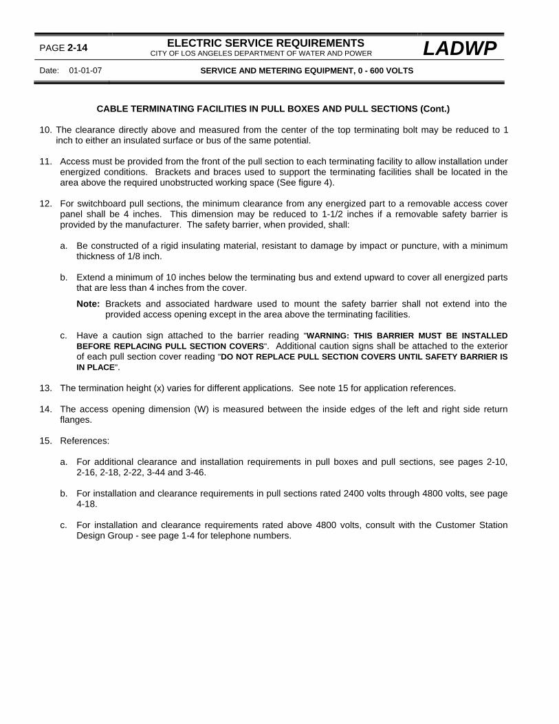
PAGE 2-14 ELECTRIC SERVICE REQUIREMENTS CITY OF LOS ANGELES DEPARTMENT OF WATER AND POWER LADWP
Date: 01-01-07 SERVICE AND METERING EQUIPMENT, 0 - 600 VOLTS
CABLE TERMINATING FACILITIES IN PULL BOXES AND PULL SECTIONS (Cont.) 10. The clearance directly above and measured from the center of the top terminating bolt may be reduced to 1
inch to either an insulated surface or bus of the same potential. 11. Access must be provided from the front of the pull section to each terminating facility to allow installation under
energized conditions. Brackets and braces used to support the terminating facilities shall be located in the area above the required unobstructed working space (See figure 4).
12. For switchboard pull sections, the minimum clearance from any energized part to a removable access cover
panel shall be 4 inches. This dimension may be reduced to 1-1/2 inches if a removable safety barrier is provided by the manufacturer. The safety barrier, when provided, shall: a. Be constructed of a rigid insulating material, resistant to damage by impact or puncture, with a minimum
thickness of 1/8 inch. b. Extend a minimum of 10 inches below the terminating bus and extend upward to cover all energized parts
that are less than 4 inches from the cover.
Note: Brackets and associated hardware used to mount the safety barrier shall not extend into the provided access opening except in the area above the terminating facilities.
c. Have a caution sign attached to the barrier reading "WARNING: THIS BARRIER MUST BE INSTALLED
BEFORE REPLACING PULL SECTION COVERS". Additional caution signs shall be attached to the exterior of each pull section cover reading "DO NOT REPLACE PULL SECTION COVERS UNTIL SAFETY BARRIER IS IN PLACE".
13. The termination height (x) varies for different applications. See note 15 for application references. 14. The access opening dimension (W) is measured between the inside edges of the left and right side return
flanges. 15. References:
a. For additional clearance and installation requirements in pull boxes and pull sections, see pages 2-10,
2-16, 2-18, 2-22, 3-44 and 3-46. b. For installation and clearance requirements in pull sections rated 2400 volts through 4800 volts, see page
4-18. c. For installation and clearance requirements rated above 4800 volts, consult with the Customer Station
Design Group - see page 1-4 for telephone numbers.

LADWP ELECTRIC SERVICE REQUIREMENTS CITY OF LOS ANGELES DEPARTMENT OF WATER AND POWER
PAGE 2-15
SERVICE AND METERING EQUIPMENT, 0 - 600 VOLTS Date 01-01-04
EUSERC DWG. 344 ALL DIMENSIONS SHOWN ARE IN INCHES
UNDERGROUND PULL BOX WITHOUT CABLE TERMINATING FACILITIES
MINIMUM PULL BOX DIMENSIONS CONDUIT SIZE "W" "H" "D"
10" 12" 4"
8" 18" 4"
3" 12" 16" 6"
8" 18" 6"
16" 24" 8"
4" 18" 30" 10"
5" 24" 36" 11"
NOTES:
1. The pull box illustrated is for use when only a single set of service entrance conductors enter the pull box. When more than one set of service entrance conductors are installed, or Y-splices are required to join the Department-installed conductors and the customer-installed conductors, install a pull box with terminating facilities.
2. Extend service entrance conductors at least 1-1/2 times the long dimension of the pull box. 3. The service supply conduit shall enter the end or the back within 2 inches of the end but shall not enter the
side. When the service supply conduit enters the end of a pull box, the opposite end shall not be less than 24 inches from obstructions projecting more than the depth of the box from the surface on which the pull box is mounted.
4. References:
a. For pull box with cable terminating facilities, see page 2-16. b. For sealing requirements, see page 2-9. c. For lifting handle requirements, see page 2-9.

PAGE 2-16 ELECTRIC SERVICE REQUIREMENTS CITY OF LOS ANGELES DEPARTMENT OF WATER AND POWER LADWP
Date: 01-01-04 SERVICE AND METERING EQUIPMENT, 0 - 600 VOLTS
EUSERC DWG. 343 ALL DIMENSIONS SHOWN ARE IN INCHES
UNDERGROUND PULL BOX WITH CABLE TERMINATIING FACILITIES 1200 AMPERES MAXIMUM
MINIMUM PULL BOX DIMENSIONS PULL BOX RATING "W" (SEE NOTE 1) "D" "X"
(AMPERES) 3-WIRE 4-WIRE 0 - 400 10-1/2" 14" 6" 22"
401 - 800 16-1/2" 22" 11" 26" 801 - 1200 22-1/2" 30" 11" 26"
NOTES:
1. The minimum access opening dimension (W) is measured between the inside edges of the left and right side return flanges.
2. Pull box access covers shall be:
a. Independent of other service equipment and removable without disturbing adjacent panels. b. Sealable, provided with lifting handles, and limited to 9 square feet in area with a maximum width or height
of 5 feet.
3. The area below the terminating facilities (shaded space) is reserved for the Department's service supply conductors.
LADWP ELECTRIC SERVICE REQUIREMENTS CITY OF LOS ANGELES DEPARTMENT OF WATER AND POWER
PAGE 2-17
SERVICE AND METERING EQUIPMENT, 0 - 600 VOLTS Date 01-01-04
UNDERGROUND PULL BOX WITH CABLE TERMINATIING FACILITIES (Cont.) 4. Customer-installed (service entrance) conductors shall leave the pull box in the area above the terminating
facilities. 5. No conduits or conductors other than the Department's service supply and the customer's service entrance
conductors shall be installed in, or routed through, the pull box. 6. Service supply conduits shall enter the bottom of the pull box. 7. References:
a. For cable terminating facility requirements, see page 2-12. b. For sealing requirements, see page 2-9. c. For lifting handle requirements, see page 2-9.

PAGE 2-18 ELECTRIC SERVICE REQUIREMENTS CITY OF LOS ANGELES DEPARTMENT OF WATER AND POWER LADWP
Date: 01-01-04 SERVICE AND METERING EQUIPMENT, 0 - 600 VOLTS
EUSERC DWG. 315 ALL DIMENSIONS SHOWN ARE IN INCHES
COMBINATION PULL BOX WITH SERVICE MAIN DISCONNECT FOR RESIDENTIAL MULTIPLE-METER SERVICES
1200 AMPERES MAXIMUM
MINIMUM PULL BOX DIMENSIONS PULL BOX RATING "W" (SEE NOTE 6) "D" "X"
(AMPERES) 3-WIRE 4-WIRE 0 - 400 10-1/2" 14" 6" 22"
401 - 800 16-1/2" 22" 11" 26" 801 - 1200 22-1/2" 30" 11" 26"
NOTES:
1. A vertical clearance of 3-inches minimum shall be maintained between the centerline of the top bolts of the terminating facilities to any obstruction.
2. A fully-enclosed, factory-installed wireway shall be provided by the manufacturer for installation of the ground
electrode conductor. The wireway shall not intrude into the required termination working space or reduce any other specified clearances.
3. A full width and depth insulated, rigid barrier shall be provided to separate the pull box area from the service
main disconnect compartment.

LADWP ELECTRIC SERVICE REQUIREMENTS CITY OF LOS ANGELES DEPARTMENT OF WATER AND POWER
PAGE 2-19
SERVICE AND METERING EQUIPMENT, 0 - 600 VOLTS Date 01-01-04
COMBINATION PULL BOX WITH SERVICE MAIN DISCONNECT (Cont.) 4. The pull section cover shall be:
a. Independent of other equipment and removable without disturbing adjacent panels. b. Sealable, provided with two lifting handles and limited to a maximum of 9 square feet in area.
5. The main disconnect cover shall be sealable. 6. The minimum access opening dimension (W) is measured between the inside edges of the left and right side
return flanges. 7. References:
a. For cable terminating facility requirements, see page 2-12. b. For sealing requirements, see page 2-9. c. For lifting handle requirements, see page 2-9.

PAGE 2-20 ELECTRIC SERVICE REQUIREMENTS CITY OF LOS ANGELES DEPARTMENT OF WATER AND POWER LADWP
Date: 01-01-07 SERVICE AND METERING EQUIPMENT, 0 - 600 VOLTS
EUSERC DWG. 301 ALL DIMENSIONS SHOWN ARE IN INCHES
COMBINATION PULL BOX AND METER SOCKET WITH SERVICE DISCONNECT FOR SINGLE-FAMILY RESIDENTIAL SERVICES
225 AMPERES MAXIMUM, 0-600 VOLTS 1∅ 3-WIRE
MINIMUM PANEL DIMENSIONS PANEL RATING CONDUIT RANGE
(AMPERES) "W" "D" "XT" "XN" SEE NOTE 6
125 6-1/2" 4" 8" 6" 1-1/4" - 2-1/2" 225 6-1/2" 5" 11" 8-1/2" 1-1/2" - 3"
Note: the “W” dimension is the minimum pull section access opening. NOTES:
1. This equipment may be constructed for underground service supply only or as a combination panel allowing either overhead/underground service supply applications.
2. Only one set of terminating facilities shall be provided and located as shown for both underground and
overhead service supply applications. The terminating facilities for the service conductors shall be aluminum-bodied, pressure-type lugs with a range of No. 6 AWG through 1/0 AWG for the 125 ampere device and 1/0 AWG through 250 KCMIL for the 225 ampere device.

LADWP ELECTRIC SERVICE REQUIREMENTS CITY OF LOS ANGELES DEPARTMENT OF WATER AND POWER
PAGE 2-21
SERVICE AND METERING EQUIPMENT, 0 - 600 VOLTS Date 01-01-07
COMBINATION PULL BOX AND METER SOCKET WITH SERVICE DISCONNECT (Cont.) 3. A minimum radial clearance of 1-1/2 inches is required between energized bus terminals and between
energized bus terminals and grounded or neutral surfaces.
Exception: The minimum clearance to the enclosure wall behind a terminating facility may be reduced to 1 inch.
4. Provide a bonding jumper or screw if the neutral terminal is insulated from the enclosure. 5. The pull section cover shall be sealable from the front and provided with a securing screw. 6. Underground service supply conduit shall enter the bottom of the terminating pull section. 7. References:
a. For sealing requirements, see page 2-9.

PAGE 2-22 ELECTRIC SERVICE REQUIREMENTS CITY OF LOS ANGELES DEPARTMENT OF WATER AND POWER LADWP
Date: 01-01-09 SERVICE AND METERING EQUIPMENT, 0 - 600 VOLTS
EUSERC DWG. 302A ALL DIMENSIONS SHOWN ARE IN INCHES
COMBINATION PULL BOX AND METER SOCKET WITH SERVICE DISCONNECT FOR SINGLE-FAMILY RESIDENTIAL SERVICES
400 AMPERES (CLASS 320), 120/240 VOLTS 1∅ 3-WIRE NOTES:
1. Meter panel shall be labeled with a 320 ampere continuous-duty rating. 2. Ringless type sockets are not permitted. 3. Socket type bypass devices of any type are not acceptable. 4. Pull box cover panels shall be removable, sealable and provided with a securing screw and lifting handles. 5. References:
a. For cable terminating facilities requirements, see page 2-12. b. For sealing requirements, see page 2-9. c. For lifting handle requirements, see page 2-9.

LADWP ELECTRIC SERVICE REQUIREMENTS CITY OF LOS ANGELES DEPARTMENT OF WATER AND POWER
PAGE 2-23
SERVICE AND METERING EQUIPMENT, 0 - 600 VOLTS Date 01-01-04
THIS PAGE LEFT INTENTIONALLY BLANK

PAGE 2-24 ELECTRIC SERVICE REQUIREMENTS CITY OF LOS ANGELES DEPARTMENT OF WATER AND POWER LADWP
Date: 01-01-04 SERVICE AND METERING EQUIPMENT, 0 - 600 VOLTS
EUSERC DWG. 342 ALL DIMENSIONS SHOWN ARE IN INCHES
TYPICAL PULL BOX ARRANGEMENTS WITH MULTI-METER PANELS FOR RESIDENTIAL SERVICES (6 METERS MAXIMUM)
200-600 AMPERES, 1∅ 3-WIRE
TYPICAL SERVICE TERMINATING ARRANGEMENTS, 2 METERS (200 AMPERES)
TYPICAL SERVICE TERMINATING ARRANGEMENTS, 3-6 METERS (201-600 AMPERES)

LADWP ELECTRIC SERVICE REQUIREMENTS CITY OF LOS ANGELES DEPARTMENT OF WATER AND POWER
PAGE 2-25
SERVICE AND METERING EQUIPMENT, 0 - 600 VOLTS Date 01-01-09
TYPICAL PULL BOX ARRANGEMENTS WITH MULTI-METER PANELS (Cont.)
EQUIPMENT RATING “W” “Y” “X” (AMPERES) SEE NOTE 2 SEE NOTES 3c AND 3d
0 - 200 6-1/2” 5-1/2” 11” 201 - 600 10-1/2” 6 22”
NOTES:
1. Pull section covers shall be removable without disturbing adjacent panels, provided with lifting handles, sealable and limited in area to 9 square feet in area.
2. The minimum pull section access opening (W) is measured between the left side and right side return flanges. 3. Terminating facilities for service supply conductors shall be provided as follows:
a. For equipment rated 200 amperes (continuous), terminations shall be aluminum-bodied, mechanical lugs with a range of 1/0 AWG through 250 KCMIL. See page 2-20 for termination details and clearance requirements
b. For equipment rated 201-600 amperes (continuous), terminations shall be two 1/2-inch steel bolts with
washers and nuts. See page 2-12 for termination details and clearance requirements. c. The neutral terminating position shall be identified. A bonding screw or jumper shall be provided if the
neutral terminal is insulated from the enclosure. d. The neutral terminating position height may be reduced to 8-1/2 inches for equipment rated 200 amperes.
4. Cross-bussing of a different phase or potential installed behind or below any terminating position shall be fully insulated or barriered. Insulating barriers shall be a rigid, nonflammable material rated for the serving voltage, resistant to ARC tracking, resistant to puncture or damage by impact, and attached with non-conducting fasteners.
5. Additional references:
a. For meter socket clearance and panel requirements, see page 3-36. b. For sealing requirements, see page 2-9. c. For lifting handle requirements, see page 2-9.

PAGE 2-26 ELECTRIC SERVICE REQUIREMENTS CITY OF LOS ANGELES DEPARTMENT OF WATER AND POWER LADWP
Date: 01-01-09 SERVICE AND METERING EQUIPMENT, 0 - 600 VOLTS
EUSERC DWG. 304 AND 305 ALL DIMENSIONS SHOWN ARE IN INCHES
SAFETY-SOCKET METER PANEL 100 AND 200 AMPERES
TABLE - MINIMUM DIMENSIONS PANEL TYPE PANEL RATING* "XT" "XN" "XD"
(AMPERES) STANDARD 100 8" 5" 2" - 3"
HEAVY-DUTY 200 11" 8" 3" - 3-1/2" NOTES:
1. Meter sockets shall be mounted on a rigid support and attached to the meter socket panel. 2. All panels shall be removable without disturbing adjacent panels. 3. Test-bypass compartment cover panel shall be sealable, and provided with a permanent label reading "DO
NOT BREAK SEALS - NO FUSES INSIDE".

LADWP ELECTRIC SERVICE REQUIREMENTS CITY OF LOS ANGELES DEPARTMENT OF WATER AND POWER
PAGE 2-27
SERVICE AND METERING EQUIPMENT, 0 - 600 VOLTS Date 01-01-09
SAFETY-SOCKET METER PANEL (Cont.) 4. Test-bypass blocks with rigid insulating barriers shall be furnished, installed, and bussed or wired to the meter
socket by the manufacturer as follows: a. For 1∅, 3-wire, provide two test-bypass blocks mounted in the outer positions and a 4-jaw socket. For
120/208 volts, 1∅ 3-wire, provide two test-bypass blocks mounted in the outer positions and a 5-jaw socket. Connect the 5th jaw of the meter socket to the neutral lug with a white No. 12 AWG (minimum) copper wire.
b. For 3∅, 3-wire, provide three test-bypass blocks and a 5-jaw meter socket - connect the line and load poles
together at the top of the center position test-bypass block with a bus section and connect the bus to the 5th jaw of the meter socket with a No. 12 AWG (minimum) copper wire. Color used to identify the wire shall not be either white, gray, green or orange.
c. For 3∅, 4-wire, provide three test-bypass blocks and a 7-jaw socket - connect the 7th jaw of the meter
socket to the neutral lug with a white No. 12 AWG (minimum) copper wire. For 120/240 volts, 4-wire delta, the right hand test-bypass block shall be the power leg (measures 208 volts-to-ground) and shall be identified with an orange color.
d. Test-bypass block connection sequence shall be LINE-LOAD from left to right and shall be clearly identified
in 3/4-inch minimum block letters. e. Cable terminals shall be aluminum-bodied mechanical lugs with a range of no. 6 AWG through 1/0 AWG
for the 100 ampere test-bypass block and no. 1/0 AWG through 250 KCMIL for the 200 ampere test-bypass block.
Note: Test-bypass compartment is not approved for use as pull box for terminating Department supply conductors.
5. One-inch (minimum) dimension measured from the edge of the compartment access opening to the test-
bypass block rigid insulating barrier. 6. 3-inch (minimum) dimension measured from the upper test connector stud (stud "A") to the socket meter cover. 7. A double insulated, bondable, vertical lay-in lug for the neutral conductor shall be provided, on either side wall,
in the test-bypass compartment. 8. Knockouts for the service supply conduit may be cut in the locations shown at the top of the panel. 9. Wiring requirements:
a. The contractor shall install and connect all line and load conductors not supplied by the manufacturer. b. No more than one set of load conductors shall exit the compartment and all load conductors shall exit
below the test-bypass blocks. 10. References:
a. For test-bypass block construction details, see page 2-32. b. For socket meter jaw arrangements, see page 2-5. c. For sealing requirements, see page 2-9.
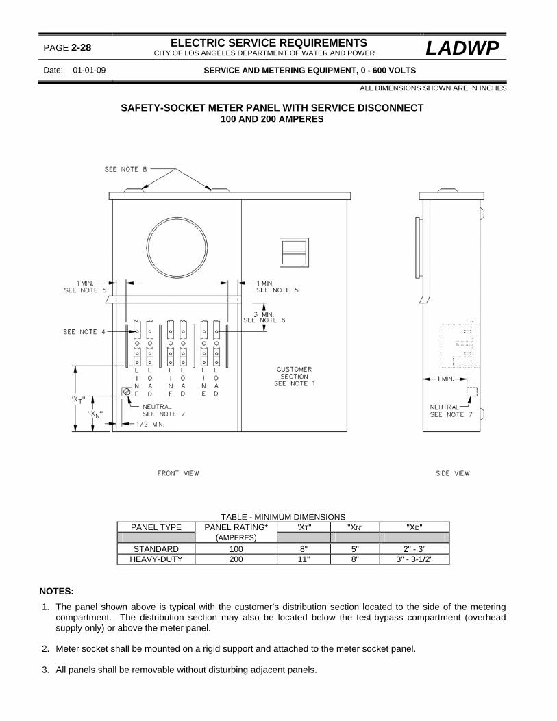
PAGE 2-28 ELECTRIC SERVICE REQUIREMENTS CITY OF LOS ANGELES DEPARTMENT OF WATER AND POWER LADWP
Date: 01-01-09 SERVICE AND METERING EQUIPMENT, 0 - 600 VOLTS
ALL DIMENSIONS SHOWN ARE IN INCHES
SAFETY-SOCKET METER PANEL WITH SERVICE DISCONNECT 100 AND 200 AMPERES
TABLE - MINIMUM DIMENSIONS PANEL TYPE PANEL RATING* "XT" "XN" "XD"
(AMPERES) STANDARD 100 8" 5" 2" - 3"
HEAVY-DUTY 200 11" 8" 3" - 3-1/2" NOTES:
1. The panel shown above is typical with the customer’s distribution section located to the side of the metering compartment. The distribution section may also be located below the test-bypass compartment (overhead supply only) or above the meter panel.
2. Meter socket shall be mounted on a rigid support and attached to the meter socket panel. 3. All panels shall be removable without disturbing adjacent panels.

LADWP ELECTRIC SERVICE REQUIREMENTS CITY OF LOS ANGELES DEPARTMENT OF WATER AND POWER
PAGE 2-29
SERVICE AND METERING EQUIPMENT, 0 - 600 VOLTS Date 01-01-09
SAFETY-SOCKET METER PANEL WITH SERVICE DISCONNECT (Cont.) 4. Test-bypass blocks with rigid insulating barriers shall be furnished, installed, and bussed or wired to the meter
socket by the manufacturer as follows: a. For 1∅, 3-wire, provide two test-bypass blocks mounted in the outer positions and a 4-jaw socket. For
12o/208 volts, 1∅ 3-wire, provide two test-bypass blocks mounted in the outer positions and a 5-jaw socket - connect the 5th jaw of the meter socket to the neutral lug with a white No. 12 AWG (minimum) copper wire.
b. For 3∅, 3-wire, provide three test-bypass blocks and a 5-jaw meter socket - connect the line and load poles
together at the top of the center position test-bypass block with a bus section and connect the bus to the 5th jaw of the meter socket with a No. 12 AWG (minimum) copper wire. Color used to identify the wire shall not be either white, gray, green or orange.
c. For 3∅, 4-wire, provide three test-bypass blocks and a 7-jaw socket - connect the 7th jaw of the meter
socket to the neutral lug with a white No. 12 AWG (minimum) copper wire. For 120/240 volts, 4-wire delta, the right hand test-bypass block shall be the power leg (measures 208 volts-to-ground) and shall be identified with an orange color.
d. Test-bypass block connection sequence shall be LINE-LOAD from left to right and shall be clearly identified
in 3/4-inch minimum block letters. e. Cable terminals shall be aluminum-bodied mechanical lugs with a range of no. 6 AWG through 1/0 AWG
for the 100 ampere test-bypass block and no. 1/0 AWG through 250 KCMIL for the 200 ampere test-bypass block.
Note: Test-bypass compartment is not approved for use as pull box for terminating Department supply conductors.
5. One-inch (minimum) dimension measured from the edge of the compartment access opening to the test-
bypass block rigid insulating barrier. 6. 3-inch (minimum) dimension measured from the upper test connector stud (stud "A") to the socket meter cover. 7. The neutral terminal may be provided as follows:
a. A single mechanical lug or lay-in lug, located on either side wall. The lug shall be mounted on a neutral bus
bar extending into, and terminating in, the customer section. b. Two mechanical lugs or lay-in lugs, located on either side wall. The neutral conductor provided from one of
the lugs to the neutral bus in the customer section may be factory or field installed. c. Overhead supply only - a single insulated, bondable, vertical, lay-in lug located on either side wall with the
neutral conductor installed unbroken through the lug and terminating on the neutral bus in the customer section.
8. Knockouts for the service supply conduit may be cut in the locations shown at the top of the panel. 9. Wiring requirements:
a. The contractor shall install and connect the line-side conductors.

PAGE 2-30 ELECTRIC SERVICE REQUIREMENTS CITY OF LOS ANGELES DEPARTMENT OF WATER AND POWER LADWP
Date: 01-01-09 SERVICE AND METERING EQUIPMENT, 0 - 600 VOLTS
SAFETY-SOCKET METER PANEL WITH SERVICE DISCONNECT (Cont.)
10. References: a. For test-bypass block construction details, see page 2-32. b. For socket meter jaw arrangements, see page 2-5. c. For sealing requirements, see page 2-9.

LADWP ELECTRIC SERVICE REQUIREMENTS CITY OF LOS ANGELES DEPARTMENT OF WATER AND POWER
PAGE 2-31
SERVICE AND METERING EQUIPMENT, 0 - 600 VOLTS Date 01-01-04
THIS PAGE LEFT INTENTIONALLY BLANK
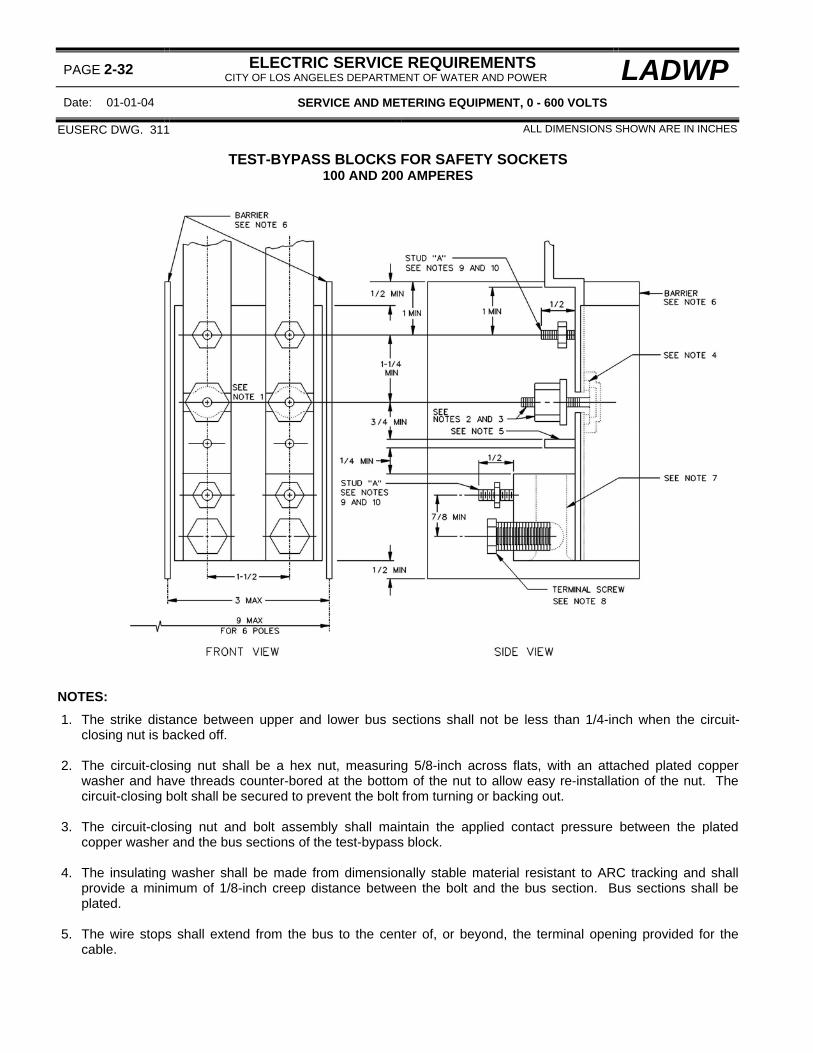
PAGE 2-32 ELECTRIC SERVICE REQUIREMENTS CITY OF LOS ANGELES DEPARTMENT OF WATER AND POWER LADWP
Date: 01-01-04 SERVICE AND METERING EQUIPMENT, 0 - 600 VOLTS
EUSERC DWG. 311 ALL DIMENSIONS SHOWN ARE IN INCHES
TEST-BYPASS BLOCKS FOR SAFETY SOCKETS 100 AND 200 AMPERES
NOTES:
1. The strike distance between upper and lower bus sections shall not be less than 1/4-inch when the circuit-closing nut is backed off.
2. The circuit-closing nut shall be a hex nut, measuring 5/8-inch across flats, with an attached plated copper
washer and have threads counter-bored at the bottom of the nut to allow easy re-installation of the nut. The circuit-closing bolt shall be secured to prevent the bolt from turning or backing out.
3. The circuit-closing nut and bolt assembly shall maintain the applied contact pressure between the plated
copper washer and the bus sections of the test-bypass block. 4. The insulating washer shall be made from dimensionally stable material resistant to ARC tracking and shall
provide a minimum of 1/8-inch creep distance between the bolt and the bus section. Bus sections shall be plated.
5. The wire stops shall extend from the bus to the center of, or beyond, the terminal opening provided for the
cable.

LADWP ELECTRIC SERVICE REQUIREMENTS CITY OF LOS ANGELES DEPARTMENT OF WATER AND POWER
PAGE 2-33
SERVICE AND METERING EQUIPMENT, 0 - 600 VOLTS Date 01-01-04
TEST-BYPASS BLOCKS FOR SAFETY SOCKETS (Cont.) 6. Rigid insulating barriers shall project at least 1/4-inch beyond any energized parts when the maximum wire size
is installed. 7. Cable terminals shall be aluminum-bodied, mechanical lugs. The hole in the terminal body for the cable shall
extend through the terminal body. If the hole opening is round, the opening shall be chamfered for ease of installation of the largest wire size.
8. The terminal screw may be of the allen type, measuring 3/16-inch across the flats, for the 100 ampere test-
bypass block and 5/16-inch across the flats for the 200 ampere test-bypass block. 9. The test connector studs ("A") shall be a 12-24 stud with a hex nut measuring 1/2 inch across the flats. 10. The test connector studs ("A") shall be provided in both the upper and lower positions as shown. In the lower
position, the studs may be located either on the terminal body, on the bus member between the circuit-closing nut and the wire stop or incorporated as part of the wire stop.
11. References:
a. For test-bypass block applications, see pages 2-26, 2-28, 2-44 and 3-34.

PAGE 2-34 ELECTRIC SERVICE REQUIREMENTS CITY OF LOS ANGELES DEPARTMENT OF WATER AND POWER LADWP
Date: 01-01-04 SERVICE AND METERING EQUIPMENT, 0 - 600 VOLTS
EUSERC DWG. 339 ALL DIMENSIONS SHOWN ARE IN INCHES
METER SOCKET PANEL WITH TEST SWITCH MOUNTING PLATE FOR INSTRUMENT-TRANSFORMER METERING INSTALLATIONS
NOTES:
1. This panel is for use with instrument-transformer metering installations requiring remote meter provisions. 2. All section covers shall be removable without disturbing adjacent covers. 3. The meter socket panel shall not be removable when the meter is in place. 4. Test switch compartment cover panel shall be sealable and provided with a label reading "DO NOT BREAK
SEAL, NO FUSES INSIDE".
5. The meter panel may be either surface mounted or semi-flush mounted. 6. References:
a. For meter socket jaw arrangements, see page 2-5. b. For sealing requirements, see page 2-9.

LADWP ELECTRIC SERVICE REQUIREMENTS CITY OF LOS ANGELES DEPARTMENT OF WATER AND POWER
PAGE 2-35
SERVICE AND METERING EQUIPMENT, 0 - 600 VOLTS Date 01-01-04
THIS PAGE LEFT INTENTIONALLY BLANK

PAGE 2-36 ELECTRIC SERVICE REQUIREMENTS CITY OF LOS ANGELES DEPARTMENT OF WATER AND POWER LADWP
Date: 01-01-04 SERVICE AND METERING EQUIPMENT, 0 - 600 VOLTS
EUSERC DWG. 314 ALL DIMENSIONS SHOWN ARE IN INCHES
CURRENT-TRANSFORMER BOX WITH METER SOCKET PANEL FOR UNDERGROUND SERVICE (See Note 1)
400 AMPERES NOTES:
1. This device may be used as a terminating pull box for an underground service. 2. The box shall be weatherproof. 3. The current-transformer compartment cover panel(s) shall be limited to 9 square feet in area, be sealable and
equipped with lifting handles and have a label reading "DO NOT BREAK SEAL - NO FUSES INSIDE". 4. The meter socket panel shall be sealable and furnished with a meter ring, meter socket and sealing ring.
"W" - MINIMUM SERVICE TYPE BOX WIDTH
1∅ or 3∅ 3-WIRE 24" 3∅ 4-WIRE 36"

LADWP ELECTRIC SERVICE REQUIREMENTS CITY OF LOS ANGELES DEPARTMENT OF WATER AND POWER
PAGE 2-37
SERVICE AND METERING EQUIPMENT, 0 - 600 VOLTS Date 01-01-04
CURRENT-TRANSFORMER BOX WITH METER SOCKET PANEL (Cont.) 5. A panel support bracket shall be provided as shown for the meter and current-transformer compartment
panels. The meter panel shall be attached to the bracket with securing screws to prevent the panel from pulling out when the meter is removed from the socket.
6. Meter socket shall be front connected. 7. The neutral termination height may be reduced to 20 inches. 8. The current-transformer mounting base shall be furnished and installed by the customer. 9. Wiring requirements:
a. The customer's load conductors shall leave the box in the area above the current-transformer mounting
base. b. No conduits or conductors other than those shown shall be installed in, or routed through, the box. c. No other meters may be supplied from the box.
10. References: a. For meter socket jaw arrangements, see page 2-5. b. For current-transformer mounting base details, see pages 2-40 and 2-42. c. For sealing requirements, see page 2-9. d. For lifting handle requirements, see page 2-9.

PAGE 2-38 ELECTRIC SERVICE REQUIREMENTS CITY OF LOS ANGELES DEPARTMENT OF WATER AND POWER LADWP
Date: 01-01-04 SERVICE AND METERING EQUIPMENT, 0 - 600 VOLTS
EUSERC DWG. 313 ALL DIMENSIONS SHOWN ARE IN INCHES
CURRENT-TRANSFORMER BOX WITH METER SOCKET PANEL FOR OVERHEAD SERVICE (See Note 1)
400 - 800 AMPERES
"W" - MINIMUM SERVICE TYPE BOX WIDTH
1∅ or 3∅ 3-WIRE 24" 3∅ 4-WIRE 36"
NOTES:
1. This device may be used for an underground service when supplied from a separate underground terminating enclosure.
2 The enclosure shall be weatherproof. 3. The current-transformer compartment cover panels shall be limited to 9 square feet in area, be sealable and
equipped with lifting handles, and have a label reading "DO NOT BREAK SEAL - NO FUSES INSIDE".

LADWP ELECTRIC SERVICE REQUIREMENTS CITY OF LOS ANGELES DEPARTMENT OF WATER AND POWER
PAGE 2-39
SERVICE AND METERING EQUIPMENT, 0 - 600 VOLTS Date 01-01-04
CURRENT-TRANSFORMER BOX WITH METER SOCKET PANEL (Cont.) 4. A panel support bracket shall be provided as shown for the meter socket and current-transformer compartment
cover panels. The meter panel shall be attached to the bracket with securing screws to prevent the panel from pulling out when the meter is removed from the socket.
5. Meter socket panel shall be sealable and furnished with a meter ring, meter socket and sealing ring. 6. Meter socket shall be front connected. 7. The current-transformer mounting base shall be furnished and installed by the customer. 8. Wiring requirements:
a. The customer's service entrance wires shall enter the box at one end and the load wires shall leave the
box at the other end. b. No conduits or conductors other than those shown shall be installed in, or routed through, the box. c. No other meters may be supplied from the box.
9. References:
a. For meter socket jaw arrangements, see page 2-5. b. For current-transformer mounting base details, see pages 2-40, 2-41, 2-42 and 2-43. c. For sealing requirements, see page 2-9. d. For lifting handle requirements, see page 2-9.

PAGE 2-40 ELECTRIC SERVICE REQUIREMENTS CITY OF LOS ANGELES DEPARTMENT OF WATER AND POWER LADWP
Date: 01-01-07 SERVICE AND METERING EQUIPMENT, 0 - 600 VOLTS
EUSERC DWG. 328A ALL DIMENSIONS SHOWN ARE IN INCHES
CURRENT-TRANSFORMER MOUNTING BASE 400 - 800 AMPERES, 1∅ 3-WIRE AND 3∅ 3-WIRE
NOTES:
1. Insulating supports shall be rated for the serving voltage and have sufficient mechanical strength for the application.
2. Two 1/2-inch steel bolts shall be provided for each current-transformer mounting position and cable terminating
position. Each bolt shall be furnished with a spring washer and a nut. The spring washer may be either split-ring washer installed with a flat washer or a conical (Belleville) washer. Bolts shall be secured in place and spaced as shown. All parts shall be plated to prevent corrosion.
Note 1: When conical washers are used, the manufacturer shall provide a readily visible label in the compartment clearly identifying the recommended torque setting for the bolt assemblies used with the washers.
Note 2: When the line or load conductors are installed by the customer, mechanical lugs may be provided in place of the studs specified above for cable terminations.
3. References:
a. For applications, see pages 2-36 and 2-38.

LADWP ELECTRIC SERVICE REQUIREMENTS CITY OF LOS ANGELES DEPARTMENT OF WATER AND POWER
PAGE 2-41
SERVICE AND METERING EQUIPMENT, 0 - 600 VOLTS Date 01-01-09
EUSERC DWG. 328B ALL DIMENSIONS SHOWN ARE IN INCHES
CURRENT-TRANSFORMER MOUNTING BASE (OVERHEAD SUPPLY) 400 - 800 AMPERES, 1∅ 3-WIRE AND 3∅ 3-WIRE
NOTES:
1. Insulating supports shall be rated for the serving voltage and have sufficient mechanical strength for the application.
2. Two 1/2-inch steel bolts shall be provided for each current-transformer mounting position. Each bolt shall be
furnished with a spring washer and a nut. The spring washer may be either split-ring washer installed with a flat washer or a conical (Belleville) washer. Bolts shall be secured in place and spaced as shown. All parts shall be plated to prevent corrosion.
Note: When conical washers are used, the manufacturer shall provide a readily visible label in the compartment clearly identifying the recommended torque setting for the bolt assemblies used with the washers.
3. Terminating positions for both load and line side conductors shall be aluminum-bodied mechanical lugs and
shall be sized to accept the conductor sizes required to supply the service. 4. References:
a. For applications, see page 2-38.

PAGE 2-42 ELECTRIC SERVICE REQUIREMENTS CITY OF LOS ANGELES DEPARTMENT OF WATER AND POWER LADWP
Date: 01-01-07 SERVICE AND METERING EQUIPMENT, 0 - 600 VOLTS
EUSERC DWG. 329A ALL DIMENSIONS SHOWN ARE IN INCHES
CURRENT-TRANSFORMER MOUNTING BASE 400 - 800 AMPERES, 3∅ 4-WIRE
NOTES:
1. Insulating supports shall be rated for the serving voltage and have sufficient mechanical strength for the application.
2. Two 1/2-inch steel bolts shall be provided for each current-transformer mounting position and cable terminating
position. Each bolt shall be furnished with a spring washer and a nut. The spring washer may be either split-ring washer installed with a flat washer or a conical (Belleville) washer. Bolts shall be secured in place and spaced as shown. All parts shall be plated to prevent corrosion.
Note 1: When conical washers are used, the manufacturer shall provide a readily visible label in the compartment clearly identifying the recommended torque setting for the bolt assemblies used with the washers.
Note 2: When the line or load conductors are installed by the customer, mechanical lugs may be provided in place of the studs specified above for cable terminations.
3. References:
a. For applications, see pages 2-36 and 2-38.

LADWP ELECTRIC SERVICE REQUIREMENTS CITY OF LOS ANGELES DEPARTMENT OF WATER AND POWER
PAGE 2-43
SERVICE AND METERING EQUIPMENT, 0 - 600 VOLTS Date 01-01-09
EUSERC DWG. 329B ALL DIMENSIONS SHOWN ARE IN INCHES
CURRENT-TRANSFORMER MOUNTING BASE (OVERHEAD SUPPLY) 400 - 800 AMPERES, 3∅ 4-WIRE
NOTES:
1. Insulating supports shall be rated for the serving voltage and have sufficient mechanical strength for the application.
2. Two 1/2-inch steel bolts shall be provided for each current-transformer mounting position. Each bolt shall be
furnished with a spring washer and a nut. The spring washer may be either split-ring washer installed with a flat washer or a conical (Belleville) washer. Bolts shall be secured in place and spaced as shown. All parts shall be plated to prevent corrosion.
Note : When conical washers are used, the manufacturer shall provide a readily visible label in the compartment clearly identifying the recommended torque setting for the bolt assemblies used with the washers.
3. Terminating positions for both load and line side conductors shall be aluminum-bodied mechanical lugs. The
number and size of the mechanical lugs provided shall be sufficient to supply the service. 4. References:
a. For applications, see page 2-38.

PAGE 2-44 ELECTRIC SERVICE REQUIREMENTS CITY OF LOS ANGELES DEPARTMENT OF WATER AND POWER LADWP
Date: 01-01-10 SERVICE AND METERING EQUIPMENT, 0 - 600 VOLTS
EUSERC DWG. 308 ALL DIMENSIONS SHOWN ARE IN INCHES
SERVICE AND METER PEDESTAL FOR COMMERCIAL SERVICES 200 AMPERES MAXIMUM
MINIMUM DIMENSIONS SERVICE “W” “A”
TYPE SEE NOTE 7a SEE NOTE 2 1∅ 3-WIRE 3∅ 3-WIRE
10-1/2”
10”
3∅ 4-WIRE 12-1/2” 10”

LADWP ELECTRIC SERVICE REQUIREMENTS CITY OF LOS ANGELES DEPARTMENT OF WATER AND POWER
PAGE 2-45
SERVICE AND METERING EQUIPMENT, 0 - 600 VOLTS Date 01-01-08
SERVICE AND METER PEDESTAL FOR COMMERCIAL SERVICES (Cont.) NOTES: 1. The meter panel shall be provided with a sealing ring and the meter socket shall be rigidly mounted on a
support and shall be attached to the meter panel. Meter height is measured from the center of the meter socket.
2. The meter shall be enclosed and the enclosing cover shall be:
a. Hinged to allow the top and front to be rotated back as one unit to expose the metering compartment. The
“A” dimension applies when the meter compartment side panels are fixed in place and obstruct the meter socket side clearance. The lifting force to open the cover shall not exceed 25 pounds.
b. Equipped with a lifting handle. c. Sealable and lockable with a padlock having a 5/16-inch lock shaft. d. Provided with a demand reset cover with a viewing window (see Fig. 4). The reset cover shall be sealable
and lockable with a padlock having a 5/16-inch lock shaft.
3. Test-bypass compartment covers shall be sealable and provided with a lifting handle. Covers exceeding 16 inches in width shall have two handles.
4. Test-bypass blocks with rigid insulating barriers shall be bussed or wired to the meter socket by the
manufacturer and provided as follows: a. For 1∅, 3-wire, provide two test-bypass blocks mounted in the outer positions and a 4-jaw socket. For
120/208 volts, 1∅ 3-wire, provide two test-bypass blocks mounted in the outer positions and a 5-jaw meter socket - connect the 5th jaw of the meter socket to the insulated neutral terminal (see note 6) with a white No. 12 AWG (minimum) copper wire.
b. For 3∅, 3-wire, provide three test-bypass blocks and a 5-jaw meter socket - connect the line and load
poles together at the top of the center position test-bypass block with a bus section and connect the bus to the 5th jaw of the meter socket with a No. 12 AWG (minimum) copper wire. The color used to identify the wire shall not be either white, gray, green or orange.
c. For 3∅, 4-wire, provide three test-bypass blocks and a 7-jaw meter socket - connect the 7th jaw of the
meter socket to the insulated neutral terminal (see note 6) with a white No. 12 AWG (minimum) copper wire. For 120/240 volts, 4-wire delta, the right side test-bypass block shall be the power leg (measuring 208 volts-to-ground) and shall be identified with an orange color.
d. Test-bypass block connection sequence shall be LINE-LOAD from left to right and clearly labeled using
3/4-inch (minimum) block letters.
5. Test-bypass blocks shall be installed with the following minimum clearances: a. 3-inches of vertical clearance from the upper test connector stud to the upper compartment access
opening and 3 inches from the center of the cable terminal screw to the lower compartment access opening.
b. 1-1/2 inches of side clearance from the outer rigid insulating barriers to the compartment sides and 1-inch
to the compartment access opening.
PAGE 2-46 ELECTRIC SERVICE REQUIREMENTS CITY OF LOS ANGELES DEPARTMENT OF WATER AND POWER LADWP
Date: 01-01-08 SERVICE AND METERING EQUIPMENT, 0 - 600 VOLTS
SERVICE AND METER PEDESTAL FOR COMMERCIAL SERVICES (Cont.) 6. An insulated neutral terminal shall be provided behind the test-bypass cover panel for 1Ø 3-wire and 3Ø 4-wire
meter sockets. The terminal shall be readily accessible when the cover panel is removed and shall be connected to the neutral terminating position in the pull section with a minimum size No. 8 AWG copper wire.
7. The terminating pull section shall:
a. Comply with the minimum dimensions shown in the table on sheet 1, be equipped with lifting handles, and
accept a minimum 3-inch conduit. The "W" dimension is measured between the access opening return flanges.
b. Be equipped with aluminum-bodied, pressure-type lugs with range of No. 6 AWG through 250 KCMIL for
termination of the service supply conductors. Insulated cable or bus shall be provided between the terminating lugs and the test-bypass facilities.
c. Have a protective metal barrier (16 gauge minimum) installed between the pull section and the customer
section. The barrier shall provide a 1/4-inch minimum clearance between the customer section wall and the barrier to prevent damage by screws and bolts projecting into the pull section area.
8. The internal barrier between the pull section and customer section shall be constructed of metal (12 gauge
minimum) and shall extend down to the concrete foundation. The barrier shall not be removable from the customer section.
9. The pull section cover shall be equipped with a lifting handle and be sealable and lockable with a padlock
having a 5/16-inch lock shaft. 10. Photoelectric sensors and similar customer-owned devices shall not be installed in the pull section or metering
compartment. 11. The pedestal shall be permanently labeled with the numeric portion of the address, in 1-inch high (minimum)
numbers, on the exterior face of the meter cover or front portion of the pedestal. 12. Pedestal shall be mounted on a substantial concrete foundation. 13. For dual-socket pedestal designs, the ampacity of each service disconnect (meter switch) shall not exceed
100 amperes. 14. References:
a. For test-bypass blocks, see page 2-32. b. For meter socket jaw arrangements, see page 2-5. c. For sealing requirements, see page 2-9. d. For lifting handle requirements, see page 2-9.

LADWP ELECTRIC SERVICE REQUIREMENTS CITY OF LOS ANGELES DEPARTMENT OF WATER AND POWER
PAGE 2-47
SERVICE AND METERING EQUIPMENT, 0 - 600 VOLTS Date 01-01-04
THIS PAGE LEFT INTENTIONALLY BLANK

PAGE 2-48 ELECTRIC SERVICE REQUIREMENTS CITY OF LOS ANGELES DEPARTMENT OF WATER AND POWER LADWP
Date: 01-01-06 SERVICE AND METERING EQUIPMENT, 0 - 600 VOLTS
EUSERC DWG. 307 ALL DIMENSIONS SHOWN ARE IN INCHES
SERVICE AND METER POST FOR MOBILE HOME (TRAILER) SERVICES 200 AMPERES MAXIMUM, 240 VOLTS MAXIMUM 1∅ 3-WIRE
NOTES:
1. The meter socket shall have a minimum rating of 100 amperes and be provided with a complete rim and sealing ring. The meter socket shall be mounted on a support and be attached to the meter panel.
2. Factory installed conductors shall be
provided from the meter socket to the cable terminating facilities and shall be connected in the terminating lugs independently of the service supply conductors.
3. The minimum depth of the post in the
ground shall be 24 inches with openings at the base to permit the service supply conduit to sweep into the post from the front (meter side).
4. The fixed panel shall extend 2 inches
minimum to 6 inches maximum above grade and 18 inches minimum below grade.
5. The meter disconnect and power outlet
section shall be barriered to prevent access to unmetered conductors.
6. The service supply cable terminating
facilities shall be No. 2 AWG through No. 350 KCMIL aluminum-bodied, pressure-type lugs. Terminating lugs may be positioned either in line or staggered and access shall be unobstructed when all service conductors are in place.
7. A minimum clearance of 1-1/2 inches shall be provided between lugs, from lugs to any grounded surface, or
from lugs to the panel above. Rigid insulated barriers are required and shall project a minimum of 1/4 inch beyond any energized parts when these clearances are reduced.
8. The neutral terminating facility shall be identified. 9. The pull section access opening (W) shall be a minimum of 7-1/2 inches in width. 10. The pull section cover shall be sealable and shall extend from the top of the fixed panel to the bottom of the
power outlet section.

LADWP ELECTRIC SERVICE REQUIREMENTS CITY OF LOS ANGELES DEPARTMENT OF WATER AND POWER
PAGE 2-49
SERVICE AND METERING EQUIPMENT, 0 - 600 VOLTS Date 01-01-05
SERVICE AND METER POST FOR MOBILE HOME(TRAILER) SERVICES (Cont.) 11. No customer load conductors or grounding conductors shall be installed in, or pass through, the pull section. 12. The pedestal shall be installed vertically and plumb. 13. An accessible equipment grounding lug shall be provided. 14. References:
a. For sealing requirements, see page 2-9. b. For lifting handle requirements, see page 2-9.

PAGE 2-50 ELECTRIC SERVICE REQUIREMENTS CITY OF LOS ANGELES DEPARTMENT OF WATER AND POWER LADWP
Date: 01-01-04 SERVICE AND METERING EQUIPMENT, 0 - 600 VOLTS
THIS PAGE LEFT INTENTIONALLY BLANK

LADWP ELECTRIC SERVICE REQUIREMENTS CITY OF LOS ANGELES DEPARTMENT OF WATER AND POWER
PAGE 3-1
LOW-VOLTAGE SWITCHBOARDS, 0 - 600 VOLTS Date 01-01-08
CONTENTS
PAGE
A. Manufacturer’s Drawings for Approval . . . . . . . . . . . . . . . . . . . . . . . . . . . . . . . . . . . . . . . . . . . . . . . . 3-3
B. Switchboard Service Sections . . . . . . . . . . . . . . . . . . . . . . . . . . . . . . . . . . . . . . . . . . . . . . . . . . . . . . . 3-3
1. General . . . . . . . . . . . . . . . . . . . . . . . . . . . . . . . . . . . . . . . . . . . . . . . . . . . . . . . . . . . . . . . . . . . . . 3-32. Instrument-Transformer Compartments . . . . . . . . . . . . . . . . . . . . . . . . . . . . . . . . . . . . . . . . . . . . 3-43. Meter Panels . . . . . . . . . . . . . . . . . . . . . . . . . . . . . . . . . . . . . . . . . . . . . . . . . . . . . . . . . . . . . . . . 3-44. Barriers . . . . . . . . . . . . . . . . . . . . . . . . . . . . . . . . . . . . . . . . . . . . . . . . . . . . . . . . . . . . . . . . . . . . 3-4
C. Meter Sockets . . . . . . . . . . . . . . . . . . . . . . . . . . . . . . . . . . . . . . . . . . . . . . . . . . . . . . . . . . . . . . . . . . 3-5
1. General . . . . . . . . . . . . . . . . . . . . . . . . . . . . . . . . . . . . . . . . . . . . . . . . . . . . . . . . . . . . . . . . . . . . 3-52. Customer-Installed Protective Devices . . . . . . . . . . . . . . . . . . . . . . . . . . . . . . . . . . . . . . . . . . . . 3-5
D. Totalized Metering . . . . . . . . . . . . . . . . . . . . . . . . . . . . . . . . . . . . . . . . . . . . . . . . . . . . . . . . . . . . . . . 3-6
E. Meter Wiring Raceway . . . . . . . . . . . . . . . . . . . . . . . . . . . . . . . . . . . . . . . . . . . . . . . . . . . . . . . . . . . . 3-6
F. Meter Sequence . . . . . . . . . . . . . . . . . . . . . . . . . . . . . . . . . . . . . . . . . . . . . . . . . . . . . . . . . . . . . . . . . 3-6
G Service Disconnects . . . . . . . . . . . . . . . . . . . . . . . . . . . . . . . . . . . . . . . . . . . . . . . . . . . . . . . . . . . . . . 3-7
1. Meter Switches . . . . . . . . . . . . . . . . . . . . . . . . . . . . . . . . . . . . . . . . . . . . . . . . . . . . . . . . . . . . . . 3-7
a. General . . . . . . . . . . . . . . . . . . . . . . . . . . . . . . . . . . . . . . . . . . . . . . . . . . . . . . . . . . . . . . . . . 3-7b. Locking Provisions . . . . . . . . . . . . . . . . . . . . . . . . . . . . . . . . . . . . . . . . . . . . . . . . . . . . . . . . . 3-7
2. Service Main Switches for Multiple-Metering . . . . . . . . . . . . . . . . . . . . . . . . . . . . . . . . . . . . . . . . 3-8
a. General . . . . . . . . . . . . . . . . . . . . . . . . . . . . . . . . . . . . . . . . . . . . . . . . . . . . . . . . . . . . . . . . . 3-8b. Locking Provisions . . . . . . . . . . . . . . . . . . . . . . . . . . . . . . . . . . . . . . . . . . . . . . . . . . . . . . . . 3-8
3. Permissible Ampacity . . . . . . . . . . . . . . . . . . . . . . . . . . . . . . . . . . . . . . . . . . . . . . . . . . . . . . . . . . 3-8
a. Single-Phase Service . . . . . . . . . . . . . . . . . . . . . . . . . . . . . . . . . . . . . . . . . . . . . . . . . . . . . . 3-8b. Three-Phase Service . . . . . . . . . . . . . . . . . . . . . . . . . . . . . . . . . . . . . . . . . . . .. . . . . . . . . . . 3-8
H. Underground Service Terminating Pull Sections . . . . . . . . . . . . . . . . . . . . . . . . . . . . . . . . . . . . . . . . . 3-9
a. General . . . . . . . . . . . . . . . . . . . . . . . . . . . . . . . . . . . . . . . . . . . . . . . . . . . . . . . . . . . . . . . . . . . 3-9b. Locations and Working Space . . . . . . . . . . . . . . . . . . . . . . . . . . . . . . . . . . . . . . . . . . . . . . . . . . . 3-9
I. Lifting Handles . . . . . . . . . . . . . . . . . . . . . . . . . . . . . . . . . . . . . . . . . . . . . . . . . . . . . . . . . . . . . . . . . 3-10
J. Sealing Requirements . . . . . . . . . . . . . . . . . . . . . . . . . . . . . . . . . . . . . . . . . . . . . . . . . . . . . . . . . . . . 3-10
K. Grounding and Bonding . . . . . . . . . . . . . . . . . . . . . . . . . . . . . . . . . . . . . . . . . . . . . . . . . . . . . . . . . . . 3-10
L. Labeling Requirements . . . . . . . . . . . . . . . . . . . . . . . . . . . . . . . . . . . . . . . . . . . . . . . . . . . . . . . . . . . 3-11
Illustrations:
Standard Switchboard Service (Metering) Section with Instrument-Transformer Compartment . . . . . 3-12
Standard Switchboard Service (Metering) Section with Instrument-Transformer Compartment and Filler Panel . . . . . . . . . . . . . . . . . . . . . . . . . . . . . . . . . . . . . . . . . . . . . . . . . . . . . . . . . . . . . . . . . 3-14
15-inch Hinged Meter Panel . . . . . . . . . . . . . . . . . . . . . . . . . . . . . . . . . . . . . . . . . . . . . . . . . . . . . . . 3-16
30-inch Hinged Meter Panel For Totalized Switchboard installations . . . . . . . . . . . . . . . . . . . . . . . . . 3-18

PAGE 3-2 ELECTRIC SERVICE REQUIREMENTS CITY OF LOS ANGELES DEPARTMENT OF WATER AND POWER LADWP
Date: 02-01-03 LOW-VOLTAGE SWITCHBOARDS, 0 - 600 VOLTS
CONTENTS (Cont.) PAGE
Instrument-Transformer Compartments:
1∅, 3-Wire, 400-1000 Amperes . . . . . . . . . . . . . . . . . . . . . . . . . . . . . . . . . . . . . . . . . . . . . . . . . 3-203∅, 3-Wire and 4-Wire, 400-1000 Amperes . . . . . . . . . . . . . . . . . . . . . . . . . . . . . . . . . . . . . . . . 3-221∅, 3-Wire, 240 Volts, 1001-3000 Amperes . . . . . . . . . . . . . . . . . . . . . . . . . . . . . . . . . . . . . . . . 3-243∅, 3-Wire and 4-Wire, 1001-3000 Amperes . . . . . . . . . . . . . . . . . . . . . . . . . . . . . . . . . . . . . . . . 3-263∅, 3-Wire and 4-Wire, Exceeding 3000 Amperes . . . . . . . . . . . . . . . . . . . . . . . . . . . . . . . . . . . 3-28
Removable Link with Current-Transformer Support for:
Single- Bolt Mounting Pattern for 4-inch Bus . . . . . . . . . . . . . . . . . . . . . . . . . . . . . . . . . . . . . . . . 3-30Two-Bolt Mounting Pattern for 5-inch Bus . . . . . . . . . . . . . . . . . . . . . . . . . . . . . . . . . . . . . . . . . . 3-32
Self-Contained Meters with Test-Bypass Blocks in Switchboards . . . . . . . . . . . . . . . . . . . . . . . . . . . . 3-34
Required Clearances on Typical Residential Multiple-Metering Arrangement . . . . . . . . . . . . . . . . . . 3-36
Outdoor or Raintight Enclosures for Switchboards . . . . . . . . . . . . . . . . . . . . . . . . . . . . . . . . . . . . . . . 3-38
Typical Switchboard Termination Arrangements for Overhead Supply . . . . . . . . . . . . . . . . . . . . . . . . 3-40
Typical Switchboard Termination Arrangements for Underground Supply . . . . . . . . . . . . . . . . . . . . . . 3-42
Standard Terminating Pull Section, Bottom Entry . . . . . . . . . . . . . . . . . . . . . . . . . . . . . . . . . . . . . . . . 3-44
Nonstandard Terminating Pull Section for Below Ground Level Installations . . . . . . . . . . . . . . . . . . . 3-46
Busway Service Heads . . . . . . . . . . . . . . . . . . . . . . . . . . . . . . . . . . . . . . . . . . . . . . . . . . . . . . . . . . . 3-48

LADWP ELECTRIC SERVICE REQUIREMENTS CITY OF LOS ANGELES DEPARTMENT OF WATER AND POWER
PAGE 3-3
LOW-VOLTAGE SWITCHBOARDS, 0 - 600 VOLTS Date 01-01-09
A. MANUFACTURER’S DRAWINGS FOR APPROVAL
1. Customers are required to consult the Department regarding all new switchboard installations and changes in metering due to load additions or modifications to existing services.
2. The Department recommends that manufacturers submit drawings for any proposed switchboard sections
to the Department for review to determine whether the proposed equipment is correctly designed for the application committed to the customer. However, manufacturers shall submit equipment drawings to the Department before fabricating the following equipment: a. All standard switchboard service sections manufactured to meet the Department’s current published
requirements (See pages 3-12 and 3-14 for typical metering arrangements).
Exception: Service sections rated up to 800 amperes that are mass produced and sold as warehouse items do not require a switchboard drawing submittal.
b. All nonstandard switchboard metering sections and pull sections.
Note: Submittals by manufacturers for approval of non-standard service equipment arrangements shall be clearly identified as requests for variance. The areas of non-compliance shall be clearly identified along with justifications for the variance request.
c. All busway service heads (See page 3-48 for construction details).
3. Drawings shall provide the following information:
a. Job Address (not delivery address). b. Manufacturer's contact with telephone and fax number. c. Voltage, ampacity and short-circuit rating information. d. Details of the equipment with panel layout, sectional view layout and dimensions; meter socket
arrangements, and appropriate ESR or EUSERC page references. Single-line type drawings are not acceptable.
e. Any other information deemed necessary for approval of the drawing.
4. Mail four copies of switchboard drawings to the service planning office (Attention: Switchboard Review) located in the area where the service is to be supplied. See page 1-4 for office locations, telephone numbers, and PAGE 1-5 for service planning area boundaries.
5. Questions regarding drawing status should be made to the service planning office where the drawings are
submitted. B. SWITCHBOARD SERVICE SECTIONS
1. GENERAL
a. A standard switchboard service section is a floor standing, metal enclosure intended for the termination of the service entrance conductors or station supply conductors. It shall be provided with panels for meters and secondary test switches, an instrument-transformer compartment and may contain the meter switch.
b. Service entrance conductors and station service supply conductors shall normally enter the top of the
section and shall leave below the bottom of the instrument-transformer compartment.

PAGE 3-4 ELECTRIC SERVICE REQUIREMENTS CITY OF LOS ANGELES DEPARTMENT OF WATER AND POWER LADWP
Date: 01-01-10 LOW-VOLTAGE SWITCHBOARDS, 0 - 600 VOLTS
B. SWITCHBOARD SERVICE SECTIONS (Cont.)
1. GENERAL (Cont.)
c. No conductors other than the standard service bussing specified in these requirements shall be installed in, or routed through, the instrument-transformer compartment.
2. INSTRUMENT-TRANSFORMER COMPARTMENTS
a. An instrument-transformer compartment is required when:
(1) The meter switch exceeds 400 amperes for residential services. (2) The meter switch exceeds 200 amperes for commercial and industrial services. (3) The service voltage exceeds 600 volts.
b. Instrument-transformer compartments shall have provisions for the installation of current-transformers, test switches and meters. For bus arrangements and dimensions, see pages 3-12 through 3-14.
c. Except for factory-installed cross bussing and service entrance conductors supplying instrument-
transformer compartments, no other conductors or devices shall be installed in, or routed through, any instrument-transformer compartment or in the sealed area above the compartment.
3. METER PANELS
a. SELF-CONTAINED METERS Meter panels as shown on Pages 3-34 and 3-36 will be provided. The removable panel and channel for test-bypass blocks may be omitted for residential multi-meter services where each occupancy is separately metered.
b. METERS WITH INSTRUMENT TRANSFORMERS
(1) Hinged meter panels with provisions for the installation of socket type meters and secondary test switches shall be furnished by the switchboard manufacturer as specified on Pages 3-16 and 3-18.
(2) Hinged meter panels shall be capable of being opened to 90 degrees with the meter and test
switch in place. The following clearances shall be provided from the socket meter panel to any obstruction: (a) 11 inches at the meter socket. (b) 4 inches at the test switch slot.
4. BARRIERS
a. When more than one switchboard section is installed, each service section shall be completely barriered from other service sections, pull sections or service switches. Barriers may have openings to allow passage of un-metered conductors between sections.
Note: The clearance between bus bars and glastic barrier shall be a maiximum of 3 inches. No barrier is shall be required between individual phase busses and the neutral bus.

LADWP ELECTRIC SERVICE REQUIREMENTS CITY OF LOS ANGELES DEPARTMENT OF WATER AND POWER
PAGE 3-5
LOW-VOLTAGE SWITCHBOARDS, 0 - 600 VOLTS Date 01-01-10
B. SWITCHBOARD SERVICE SECTIONS (Cont.)
b. Barriers used to separate customer sections from utility sections (i.e., pull sections and metering
sections) and sections containing unmetered conductors or bus shall be constructed from 16-gauge (minimum) steel and shall be secured with devices that are not removable from either the customer sections or the exterior of the switchboard.
Exception: The barrier between sealed utility metering sections and the terminating pull section may be 1/8” minimum glastic or equivalent.
c. Where an instrument-transformer compartment is supplied by cabling provided from an adjacent pull
section, an opening shall be provided in the barrier between the sections above the instrument-transformer compartment. The bottom edge of the opening shall be rolled to protect the conductors from damage.
e. Where a load wireway is equipped with unmetered cross bussing the cross bussing shall be barriered
to isolate the bus from the customer’s load conductors.
C. METER SOCKETS 1. GENERAL
a. Every new switchboard installation shall be equipped with a meter socket (without bypass devices) and
an approved sealing ring. Sockets shall have the jaw arrangement specified for the voltage and phase to be metered. See page 2-5 for socket jaw arrangements.
b. Meter sockets shall be provided with jaws or clips of beryllium copper, be listed by Underwriters
Laboratories (UL) and conform to ANSI Standard C12.7. c. Self-contained meters shall be attached to a rigid stationary support and be attached to the meter
panel to assure alignment of the socket ring to the socket jaws and to prevent removal of the panel with the meter installed.
d. Instrument-transformer rated sockets shall be designed for back connection. Sockets shall be installed
with machine screws so the socket can be easily interchanged or replaced.
Note: Screws used to mount cast meter sockets to meter panels shall provide a 1/8” minimum clearance between the screw head and the back of the meter socket ring.
e. Ringless or gasketed type metered sockets are not permitted. f. All meter fittings shall be mounted on a substantial support in a true vertical position. g. For commercial and industrial multi-meter installations, no more than two meters may be mounted on a
single removable panel unless the design permits replacement of individual meter sockets without disturbing adjacent meters secured with sealing or locking rings.
h. For residential multi-meter installations, no more than one meter may be mounted on a single
removable panel unless the design permits replacement of individual meter sockets without disturbing adjacent meters secured with sealing or locking rings.
2. CUSTOMER-OWNED PROTECTIVE DEVICES
Customer-owned surge-arrestors, fuses or other protective devices shall not be installed between the meter socket and the Department’s electric meter.

PAGE 3-6 ELECTRIC SERVICE REQUIREMENTS CITY OF LOS ANGELES DEPARTMENT OF WATER AND POWER LADWP
Date: 01-01-09 LOW-VOLTAGE SWITCHBOARDS, 0 - 600 VOLTS
D. TOTALIZED METERING
1. While the Department is not required to provide totalized metering for the customer's convenience,
requests for totalizing will be considered on an individual basis. Totalizing is limited to instrument-rated switchboard installations.
2. Where the Department provides totalized metering for the customer's convenience, the customer shall
reimburse the Department for the Department's estimated cost of the totalized service exceeding the cost of a standard (not totalized) metering installation.
3. Metering sections to be totalized shall be in the same room or at an adjacent location with access provided
through a doorway not less than 30 inches wide and 6 feet high. 4. Each metering section to be totalized shall be provided with a separate underground terminating enclosure
or overhead wiring raceway. For overhead services, see page 7-15, SERVICE HEADS-LOCATIONS, for spacing requirements.
5. Metering sections to be totalized shall be provided with a secondary wiring enclosure between the
sections. See METER WIRING RACEWAY for additional requirements.
E. METER WIRING RACEWAY 1. A wiring raceway shall be installed between:
a. A remote meter panel and its related instrument-transformer compartment. b. Instrument-transformer compartments that are to be totalized.
Note: The wiring raceway between metering sections to be totalized shall not exceed 40 feet in length.
2. The wiring raceway shall consist of either a single rigid conduit, or electric metallic tubing of 1-inch
(minimum) trade size or a sealable raceway. 3. The wiring raceway shall enter the top of the instrument-transformer compartment within 3 inches of the
front of the compartment and within 3 inches of either side of the compartment. Adjacent compartments may be connected by a 1-inch chase nipple at the same level and in front of the upper support bar.
4. A standard doorway shall be provided between totalized instrument-transformer compartments or between
an instrument-transformer compartment and its related (remote) meter socket.
F. METER SEQUENCE
1. Every single meter socket shall be installed on the line side of its related meter switch (NEW SEQUENCE). 2. For multiple meter installations where a service main switch is required or permitted on the line side of the
meter sockets (OLD SEQUENCE), the switch shall be located adjacent to its related meter sockets.
Exception: For large multi-story buildings or other installations where the Department has approved meters in multiple or remote locations and the Permitting Authority has required a (controlling) service disconnect device at the source location to protect the service entrance conductors, the adjacent disconnect device at the remote meter location is not required provided:

LADWP ELECTRIC SERVICE REQUIREMENTS CITY OF LOS ANGELES DEPARTMENT OF WATER AND POWER
PAGE 3-7
LOW-VOLTAGE SWITCHBOARDS, 0 - 600 VOLTS Date 01-01-09
F. METER SEQUENCE (Cont.)
a. The meter switch or service main switch for the metering equipment shall control all
electric load to a specific area and is labeled to indicate the controlled area (i.e., occupancy, load served, etc.)
b. The metering equipment is located in a publicly accessible area and is labeled to clearly
identify the controlling service switch and its location. c. The controlling service switch is capable of being locked in the open position.
3. To prevent energy diversion, unmetered runs of service entrance conductors supplying remote meter
location shall be enclosed in an unbroken conduit run. The Department reserves the right to inspect these conduit runs during and subsequent to the installation.
Exception: pull boxes, condulettes and LB condulettes when required by the permitting agency for cable support or pulling needs shall be installed in meter rooms. Condulettes and LB condulettes installed in other locations require approval of the Department prior to installation.
G. SERVICE DISCONNECTS
1. METER SWITCHES
a. GENERAL (1) The customer shall furnish and install a service disconnect device (meter switch) such as a circuit
breaker, fused switch or other approved disconnect device with over-current protection on the load side of each and every meter.
(2) The meter switch shall control all of, and only, the energy registered by the meter. (3) The meter switch may consist of a group of up to six separate disconnect devices grouped at a
single location. (4) When separate switchboard service sections are totalized, a meter switch will be required for
each service section.
b. LOCKING PROVISIONS
Meter switches provided for instrument-transformer compartments shall be capable of being locked in the open (off) position using a standard Department padlock having a 5/16-inch lockshaft and a 1-inch locking clearance. Locking provisions shall consist of: (1) A lockout device that is incorporated as an integral part of each meter switch, or (2) A lockable cover for each meter switch where the lock prevents operation of the switch and
prevents removal of the cover, or (3) A lockable cover for multiple meter switches supplied from a single instrument-transformer
compartment where the lock prevents operation of the switch and prevents removal of the cover.
Note: Each of the alternate locking provisions described above may be accomplished up to two (2) padlocks per meter switch. Where two padlocks are required to lock a meter switch in the open position, the locking points shall be readily identifiable.
(4) For fused switches, the fuse access cover shall be lockable when the switch is locked in the open
(off) position.

PAGE 3-8 ELECTRIC SERVICE REQUIREMENTS CITY OF LOS ANGELES DEPARTMENT OF WATER AND POWER LADWP
Date: 01-01-07 LOW-VOLTAGE SWITCHBOARDS, 0 - 600 VOLTS
G. SERVICE DISCONNECTS (Cont.)
2. SERVICE MAIN SWITCHES FOR MULTIPLE METERING
a. GENERAL
A service main switch shall consist of either a circuit breaker, fused disconnect, or other approved disconnecting means located on the line side (OLD SEQUENCE) of its group of related meters.
Note: A main service switch shall not be installed on the line side of a single meter socket.
b. LOCKING PROVISIONS (1) The service main switch shall be required to be lockable in the open (off) position when:
(a) The service main disconnect is not adjacent to (i.e., within reasonable proximity and line of
sight) its related group of meters, or (b) Otherwise specified by the Department.
(2) Locking provisions shall consist of: (a) A lockout device that is incorporated as an integral part of each meter switch, or (b) A lockable cover for the service switch where the lock prevents operation of the switch and
prevents removal of the cover.
3. PERMISSIBLE AMPACITY
a. SINGLE-PHASE SERVICE
A single-phase service shall not supply a service switch in excess of 600 amperes, 120/240 volt, three-wire. Where a switch of greater ampacity is required, the Department's approval must be obtained as to the required number of sets of service entrance conductors, load balance, and related metering facilities prior to supplying service.
b. THREE-PHASE SERVICE
In general, there is no limit to the ampacity of a service switch for a three-phase service. Only a single service with a single set of metering equipment for the entire load will be permitted at any service location. When the anticipated load requires a switch exceeding 3000 amperes, the Department shall be consulted for engineering information prior to designing the installation.

LADWP ELECTRIC SERVICE REQUIREMENTS CITY OF LOS ANGELES DEPARTMENT OF WATER AND POWER
PAGE 3-9
LOW-VOLTAGE SWITCHBOARDS, 0 - 600 VOLTS Date 01-01-05
H. UNDERGROUND SERVICE TERMINATING PULL SECTIONS
1. GENERAL
a. Underground service supply conduits installed from the Department’s underground electric system (or pole dips from the overhead electric system) to the customer’s metering equipment shall terminate in an approved underground terminating enclosure. For approved terminating enclosure arrangements, see pages 2-13, 2-14, 3-44 and 3-46.
CAUTION: Service supply conduits shall not enter any terminating enclosure above either the cable terminating facilities or other energized bussing. Terminating enclosures shall be located so that any moisture entering the enclosure from the service conduits will not enter the customer’s service equipment.
b. For services rated up to 2000 amperes, the service supply conduits may enter either the bottom or
back of the switchboard pull section - see page 3-46 for details and restrictions on back-entry conduit. For services exceeding 2000 amperes, the service supply conduits shall enter the bottom.
Note: Special termination enclosure arrangements must be approved by the Department before installing any facilities.
c. Except for the Department's service supply conductors and the customer's service entrance
conductors, no other conductors or devices (i.e., fuses, surge arrestors, current-transformers and other customer-owned wiring or devices) shall be installed in , or routed through, any underground pull section enclosure.
2. LOCATIONS AND WORKING SPACE
a. The service terminating pull section shall be readily accessible and located on the exterior wall of a building or other approved permanent structure, in an approved meter room on the first floor or basement parking level or other locations as the Department may designate.
b. Pull section locations prohibited:
(1) In any meter room, storage room or basement area in any single-family dwelling.
Note: Pull sections shall be located to be accessible without entering any building. (2) In any occupancy of any multiple-tenant building. (3) In any rest, bath, toilet, shower, dressing room or in any room accessed through such areas. (4) In any hazardous location. (5) In any other location judged unacceptable to the Department.
c. Pull sections shall be provided with a level, unobstructed working space in front of the entire pull section. The minimum required working space shall be 3 feet in width, extend 3 feet from the front of the pull section, and extend to the top of the section but not less than 6 feet - 6 inches.
PAGE 3-10 ELECTRIC SERVICE REQUIREMENTS CITY OF LOS ANGELES DEPARTMENT OF WATER AND POWER LADWP
Date: 01-01-09 LOW-VOLTAGE SWITCHBOARDS, 0 - 600 VOLTS
I. LIFTING HANDLES
1. Removable cover panels shall be equipped with a lifting handle. Cover panels in excess of 3 square feet
shall require two lifting handles. The handles shall be located so as to provide control and balance while the panel is being removed.
2. Hinged meter panels shall be equipped with a handle on the side opposite the hinges. 3. Handles shall be sized for full-hand grasping, securely attached, and have strength to withstand handling
stresses of not less than 75 pounds. Folding or hinged handles are not acceptable.
J. SEALING REQUIREMENTS 1. All removable panels providing access to compartments containing unmetered conductors shall be
sealable including customer load wireways. No removable panel or cover requiring sealing shall be located behind any other panel, cover or door (except raintight enclosure doors).
2. Sealable latches, captive stud assemblies, or sealing screws may be used for sealing and shall be installed
so as to prevent a sealed cover from being opened or removed without breaking the seal. 3. Non-hinged removable covers shall be sealed with captive stud assemblies on opposite sides of the cover.
Alternate sealing methods may be used if the removable cover is self-supporting with the securing screws and sealing provisions removed.
4. Hinged covers or panels shall be sealed on the side opposite the hinges. 5. Captive stud assemblies shall consist of a 1/4-inch-20 (minimum) stud, and associated wing-nut, each
drilled 0.0635 inch (minimum) for sealing purposes. The stud shall be securely attached so as to not loosen or back out when being fastened.
K. GROUNDING AND BONDING
1. GROUNDING
a. Manufacturers shall not provide a termination lug for the customer’s grounding conductor in any
compartment sealed or locked by the Department.
Exceptions: A grounding terminal is permitted in a main service switch compartment or, when required by the permitting agency for services supplied overhead, in a sealed wireway used to supply more than one meter socket.
b. Where busway having an integral or internal ground is used to supply an instrument-transformer
compartment, a ground bus (not cable) shall be permitted to pass through the compartment for connection to the busway grounding provision provided it is located at the side or rear of the compartment and does infringe on any of the specified bus or working space clearances.
c. The grounding electrode conductor shall not be installed in, or routed through, any compartment
sealed or locked by the Department.

LADWP ELECTRIC SERVICE REQUIREMENTS CITY OF LOS ANGELES DEPARTMENT OF WATER AND POWER
PAGE 3-11
LOW-VOLTAGE SWITCHBOARDS, 0 - 600 VOLTS Date 01-01-09
K. GROUNDING AND BONDING (Cont.)
2. BONDING a. Ground bus units installed by manufacturers to provide bonding between equipment sections are
permitted in compartments sealed or locked by the Department. Ground bus units provided in underground terminating pull sections shall be located in the rear of the compartment. See item 1 under “Grounding” regarding placement of the terminal lug for the customer’s ground conductor.
b. Conduit bonding jumpers shall be terminated at the closest available point where the conduit to be
bonded enters an underground terminating enclosure or metering compartment. L. LABELING REQUIREMENTS
1. Meter and service equipment shall be provided with a manufacturer’s label identifying the metered voltage,
phase, ampacity and rated short-circuit duty (when applicable). 2. Meter and service equipment shall be provided with a label identifying the nationally recognized testing
laboratory that has tested and listed the equipment. 3. Multi-voltage rated service and metering equipment shall be identified with the metered voltage.
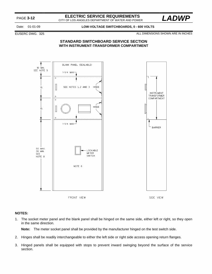
PAGE 3-12 ELECTRIC SERVICE REQUIREMENTS CITY OF LOS ANGELES DEPARTMENT OF WATER AND POWER LADWP
Date: 01-01-09 LOW-VOLTAGE SWITCHBOARDS, 0 - 600 VOLTS
EUSERC DWG. 325 ALL DIMENSIONS SHOWN ARE IN INCHES
STANDARD SWITCHBOARD SERVICE SECTION WITH INSTRUMENT-TRANSFORMER COMPARTMENT
NOTES:
1. The socket meter panel and the blank panel shall be hinged on the same side, either left or right, so they open in the same direction.
Note: The meter socket panel shall be provided by the manufacturer hinged on the test switch side. 2. Hinges shall be readily interchangeable to either the left side or right side access opening return flanges. 3. Hinged panels shall be equipped with stops to prevent inward swinging beyond the surface of the service
section.

LADWP ELECTRIC SERVICE REQUIREMENTS CITY OF LOS ANGELES DEPARTMENT OF WATER AND POWER PAGE 3-13
LOW-VOLTAGE SWITCHBOARDS, 0 - 600 VOLTS Date 01-01-08
STANDARD SWITCHBOARD SERVICE SECTION (Cont.) 4. Removable or hinged panels enclosing unmetered bus or cable shall be sealable. 5. Dimension may be reduced if the service section is supplied from horizontal cross bussing or bus duct. 6. Compartment may be used as an underground pull section for termination of the Department's service supply
conductors in a bottom feed service section. 7. The customer's grounding connection shall be located in the customer's load section. No grounding conductor
or conduit shall be routed through the instrument-transformer compartment or in the pull section when constructed as a bottom-feed service section.
8. Dimension measured from the top surface of the horizontal barrier. 9. References:
a. For instrument-transformer compartments:
(1) 1∅ and 3∅, 3-wire: 400-1000 amperes, see page 3-20.
1001-3000 amperes, see page 3-24. (2) 3∅, 3-wire and 4-wire: 400-1000 amperes, see page 3-22.
1001-3000 amperes, see page 3-26.
3001 amperes and above, see page 3-28.
b. For sealing requirements, see page 3-10. c. For lifting handle requirements, see page 3-10. d. For meter disconnect locking requirements, see page 3-7. e. For socket meter panel requirements, see pages 3-16 and 3-18. f. For weatherproof (3R) enclosure requirements, see page 3-38. g. For pull section requirements for a bottom-feed service section, see page 3-44. h. For barrier requirements, see page 3-4.
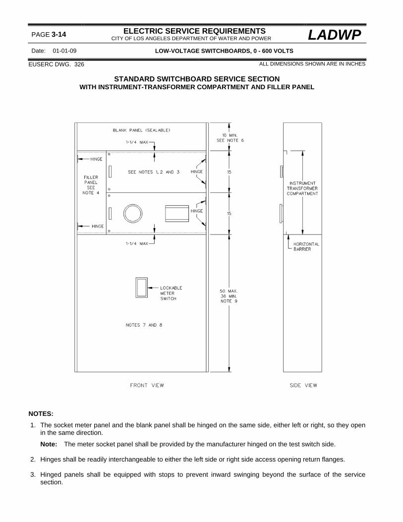
PAGE 3-14 ELECTRIC SERVICE REQUIREMENTS CITY OF LOS ANGELES DEPARTMENT OF WATER AND POWER LADWP
Date: 01-01-09 LOW-VOLTAGE SWITCHBOARDS, 0 - 600 VOLTS
EUSERC DWG. 326 ALL DIMENSIONS SHOWN ARE IN INCHES
STANDARD SWITCHBOARD SERVICE SECTION WITH INSTRUMENT-TRANSFORMER COMPARTMENT AND FILLER PANEL
NOTES:
1. The socket meter panel and the blank panel shall be hinged on the same side, either left or right, so they open in the same direction.
Note: The meter socket panel shall be provided by the manufacturer hinged on the test switch side. 2. Hinges shall be readily interchangeable to either the left side or right side access opening return flanges. 3. Hinged panels shall be equipped with stops to prevent inward swinging beyond the surface of the service
section.
LADWP ELECTRIC SERVICE REQUIREMENTS CITY OF LOS ANGELES DEPARTMENT OF WATER AND POWER PAGE 3-15
LOW-VOLTAGE SWITCHBOARDS, 0 - 600 VOLTS Date 01-01-08
STANDARD SWITCHBOARD SERVICE SECTION (Cont.) 4. A hinged filler panel is required when the switchboard frame width exceeds the maximum allowable meter panel
width. Meter panels, either socket type or blank, shall not be hinged to a hinged filler panel. Non-hinged filler panels shall not intrude into the required instrument-transformer compartment clearances.
5. Removable or hinged panels enclosing unmetered bus or cable shall be sealable. 6. Dimension may be reduced if the service section is supplied from horizontal cross bussing or bus duct. 7. Compartment may be used as an underground pull section for termination of the Department's service supply
conductors in a bottom feed service section. 8. The customer's grounding connection shall be located in the customer's load section. No grounding conductor
or conduit shall be routed through the instrument-transformer compartment or in the pull section when constructed as a bottom-feed service section.
9. Dimension measured from the top surface of the horizontal barrier. 10. References:
a. For instrument-transformer compartments:
(1) 1∅ and 3∅, 3-wire: 400-1000 amperes, see page 3-20.
1001-3000 amperes, see page 3-24. (2) 3∅, 3-wire and 4-wire: 400-1000 amperes, see page 3-22.
1001-3000 amperes, see page 3-26.
3001 amperes and above, see page 3-28. b. For sealing requirements, see page 3-10 c. For lifting handle requirements, see page 3-10. d. For meter disconnect locking requirements, see page 3-7. e. For socket meter panel requirements, see pages 3-16 and 3-18. f. For weatherproof (3R) enclosure requirements, see page 3-38. g. For pull section requirements for a bottom-feed service section, see page 3-44. h. For barrier requirements, see page 3-4.

PAGE 3-16 ELECTRIC SERVICE REQUIREMENTS CITY OF LOS ANGELES DEPARTMENT OF WATER AND POWER LADWP
Date: 01-01-08 LOW-VOLTAGE SWITCHBOARDS, 0 - 600 VOLTS
EUSERC DWG. 332 ALL DIMENSIONS SHOWN ARE IN INCHES
15-INCH HINGED METER PANEL

LADWP ELECTRIC SERVICE REQUIREMENTS CITY OF LOS ANGELES DEPARTMENT OF WATER AND POWER
PAGE 3-17
LOW-VOLTAGE SWITCHBOARDS, 0 - 600 VOLTS Date 01-01-06
15-INCH HINGED METER PANEL (Cont.) NOTES:
1. A standard metering installation shall consist of a hinged socket meter panel in the lower position and a hinged panel blank (not shown) in the upper position. The panels shall be constructed of 12-gauge (minimum) steel and installed so that both panels open in the same direction.
2. The socket meter panel shall be furnished with a meter ring, meter socket, sealing ring and a slotted opening
with a removable plate for installation of a test switch. The plate shall be attached to the rear of the panel with screws that do not protrude through the face of the panel and the edges of the plate and the slotted opening shall be smooth to prevent damage to the meter wiring.
Note: Screws used to mount cast meter sockets to meter panels shall provide a 1/8” minimum clearance between the screw head and the back of the meter socket ring.
3. The panels shall have a handle at the unsupported end. The handle on the socket meter panel shall be readily
interchangeable, left to right side, and shall be located not less than 1 inch from the meter socket ring. 4. The hinges shall permit the panels to open to 90-degrees or more. The hinges on the socket meter panel shall
be readily interchangeable, left to right side Clevis or removable pin type hinges shall be removable from the top.
5. The panels shall support a 25-pound force applied at the unsupported end of the panels, when fully opened,
with a maximum sag of 1/8 inch. 6. Meter panels shall be sealable on the side opposite the hinges using either sealing screws or stud and wing-
nut assemblies. 7. References:
a. For meter panel applications, see pages 3-12 and 3-14. b. For meter socket jaw arrangements, see page 2-5. c. For sealing requirements, see page 3-10. d. For lifting handle requirements, see page 3-10.

PAGE 3-18 ELECTRIC SERVICE REQUIREMENTS CITY OF LOS ANGELES DEPARTMENT OF WATER AND POWER LADWP
Date: 01-01-08 LOW-VOLTAGE SWITCHBOARDS, 0 - 600 VOLTS
ALL DIMENSIONS SHOWN ARE IN INCHES
30-INCH HINGED METER PANEL FOR TOTALIZED SWITCHBOARD INSTALLATIONS NOTES:
1. For totalized metering installations, install a socket meter panel as shown on each switchboard service section to be totalized.
2. Panel shall be constructed of 12-gauge (minimum) steel.

LADWP ELECTRIC SERVICE REQUIREMENTS CITY OF LOS ANGELES DEPARTMENT OF WATER AND POWER
PAGE 3-19
LOW-VOLTAGE SWITCHBOARDS, 0 - 600 VOLTS Date 01-01-05
30-INCH HINGED METER PANEL FOR TOTALIZED SWITCHBOARD INSTALLATIONS (Cont.) 3. The panel shall be furnished with a meter ring, meter socket, sealing ring and a slotted opening with a
removable plate for installation of a meter test switch. The plate shall be attached to the rear of the panel with screws that do not protrude through the face of the panel and the edges of the plate and the edges of the slotted opening shall be smooth to prevent damage to meter wiring.
Note: When a cast meter ring is provided, there shall be a minimum clearance of 1/8” between the head of the screw used to mount the cast ring to the panel and the back of the meter socket ring.
4. The panel shall have a handle attached to both sides. The handle shall not be less than 1 inch from the meter
socket ring. 5. The hinges shall be readily interchangeable, left to right side, on the panel and permit the panel to open
90-degrees or more. Clevis or removable pin type hinges shall be removable from the top. 6. The panel shall support a 25-pound force applied at the unsupported end of the panel when fully opened with
maximum sag of 1/8 inch. 7. The panel shall be sealable using either sealing screws or stud and wing-nut assemblies. 8. References:
a. For meter panel applications, see pages 3-12 and 3-14. b. For meter socket jaw arrangements, see page 2-5. c. For sealing requirements, see page 3-10. d. For lifting handle requirements, see page 3-10.

PAGE 3-20 ELECTRIC SERVICE REQUIREMENTS CITY OF LOS ANGELES DEPARTMENT OF WATER AND POWER LADWP
Date: 01-01-09 LOW-VOLTAGE SWITCHBOARDS, 0 - 600 VOLTS
EUSERC DWG. 319 ALL DIMENSIONS SHOWN ARE IN INCHES
INSTRUMENT-TRANSFORMER COMPARTMENT FOR SWITCHBOARDS 400-1000 AMPERES, 1∅ 3-WIRE AND 3∅ 3-WIRE (See Note 9)
1. Bus arrangements and supports shall be provided as shown, except the neutral bus may be located on either
sidewall or at either side. Bus supports shall be constructed of a continuous bar of non-conducting material and shall be rigid to prevent misalignment of the bus units with the cables installed.
LADWP ELECTRIC SERVICE REQUIREMENTS CITY OF LOS ANGELES DEPARTMENT OF WATER AND POWER
PAGE 3-21
LOW-VOLTAGE SWITCHBOARDS, 0 - 600 VOLTS Date 01-01-07
INSTRUMENT-TRANSFORMER COMPARTMENT FOR SWITCHBOARDS (Cont.) 400-1000 AMPERES, 1∅ 3-WIRE AND 3∅ 3-WIRE
NOTES:
2. The current-transformer bus units may be supplied from the either the top or the bottom and shall be anchored to prevent misalignment. The bus units shall be constructed of rectangular bus and when laminated shall have no space between laminations. Bus dimensions shall be provided as follows:
Minimum: 1/4 inch by 2 inches Maximum: 3/4 inch by 2 inches
3. Bus units shall be provided with fixed studs as shown for mounting the current-transformers. Each stud shall
consist of a 1/2-inch steel bolt that is secured in place and provided with a spring washer and a nut. The spring washer may be either a split-ring washer installed with a flat washer or conical (Belleville) washer. All parts shall be plated to prevent corrosion.
Note: When conical washers are used, the manufacturer shall provide a readily visible label in the current-transformer compartment clearly identifying the recommended torque setting for the bolt assemblies used with the washers.
4. Except for bus supplying the instrument-transformer compartment, no other conductors or devices shall be
installed in, or routed through, the compartment or the sealed area above the compartment.
Exception: Where busway having an integral or internal ground is used to supply the compartment, a ground bus (not cable) shall be permitted to pass through the compartment for connection to the busway grounding provision provided it is located at the side or rear of the compartment and does infringe on any of the specified bus or working space clearances.
5. A clear unobstructed workspace shall be provided, as shown, around the current-transformer bus units from
the horizontal barrier to the bottom of the upper bus support bar. 6. A 10-32 screw and washer (tap) for meter wiring shall be provided on the neutral bus, as shown, or on the
neutral cross-bus supplying the compartment or on a bus bar extension provided from the neutral cross-bus. The tap shall be located a minimum of 1-1/2 inches above the horizontal barrier (Note 7) and located between the phase bus units, or at either side, and shall be readily accessible under energized conditions and with the Department's current-transformers installed.
Note: For 3∅ 3-wire a tap is required on the B∅ bus (neutral) unit.
7. The horizontal barrier shall be constructed of a rigid insulating material resistant to ARC tracking and shall be secured in place with a maximum deflection of 1/2 inch from an applied force of 25 pounds downward. Openings in the barrier (i.e., peripheral gaps around barrier, cutouts around bus bars, and holes provided for ventilation) shall not exceed 3/8 inch. The barrier shall be attached with nonconductive fasteners.
8. Dimension measured between the inside edges of the compartment access opening. 9. References:
a. For instrument-transformer compartment applications, see pages 3-12 and 3-14. b. 3∅ 3-wire is not a standard service voltage. For application limitations, see page 1-25.

PAGE 3-22 ELECTRIC SERVICE REQUIREMENTS CITY OF LOS ANGELES DEPARTMENT OF WATER AND POWER LADWP
Date: 01-01-09 LOW-VOLTAGE SWITCHBOARDS, 0 - 600 VOLTS
EUSERC DWG. 320 ALL DIMENSIONS SHOWN ARE IN INCHES
INSTRUMENT-TRANSFORMER COMPARTMENT FOR SWITCHBOARDS 400-1000 AMPERES, 3∅ 4-WIRE AND 3-WIRE (See Note 11)
NOTES:
1. Bus arrangements and supports shall be provided as shown, except that the neutral bus may be located on either sidewall or at either side. Bus supports shall be constructed of a continuous bar of non-conducting material and shall be rigid to prevent misalignment of the bus units with the cable in place.

LADWP ELECTRIC SERVICE REQUIREMENTS CITY OF LOS ANGELES DEPARTMENT OF WATER AND POWER
PAGE 3-23
LOW-VOLTAGE SWITCHBOARDS, 0 - 600 VOLTS Date 01-01-08
INSTRUMENT-TRANSFORMER COMPARTMENT FOR SWITCHBOARDS (Cont.) 400-1000 AMPERES, 3∅ 4-WIRE AND 3-WIRE
2. The current-transformer bus units may be supplied from the top or the bottom and shall be anchored to prevent
misalignment. The bus units shall be constructed of rectangular bus and when laminated shall have no space between laminations. Bus dimensions shall be provided as follows:
Minimum: 1/4 inch by 2 inches Maximum: 3/4 inch by 2 inches
3. Bus units shall be provided with fixed studs as shown for mounting the current-transformers. Each stud shall
consist of a 1/2-inch steel bolt that is secured in place and provided with a spring washer and a nut. The spring washer may be either a split-ring washer installed with a flat washer or conical (Belleville) washer. All parts shall be plated to prevent corrosion.
Note: When conical washers are used, the manufacturer shall provide a readily visible label in the current-transformer compartment clearly identifying the recommended torque setting for the bolt assemblies used with the washers.
4. Except for bus supplying the instrument-transformer compartment, no other conductors or devices shall be
installed in, or routed through, the compartment or the sealed area above the compartment.
Exception: Where busway having an integral or internal ground is used to supply the compartment, a ground bus (not cable) shall be permitted to pass through the compartment for connection to the busway grounding provision provided it is located at the side or rear of the compartment and does infringe on any of the specified bus or working space clearances.
5. A clear unobstructed workspace shall be provided, as shown, around the current-transformer bus units from
the horizontal barrier to the bottom of the upper bus support bar. 6. A 10-32 screw and washer (tap) for meter wiring shall be provided on the neutral bus unit as shown or on the
neutral cross-bus supplying the compartment or on a bus bar extension provided from the neutral cross-bus. The tap shall be located a minimum of 1-1/2 inches above the horizontal barrier (note 7) and located between the phase bus units, or at either side, and shall be readily accessible under energized conditions and with the Department's current-transformers installed.
7. The horizontal barrier shall be constructed of a rigid insulating material resistant to ARC tracking and shall be secured in place with a maximum deflection of 1/2 inch from an applied force of 25 pounds downward. Openings in the barrier (i.e., peripheral gaps around barrier, cutouts around bus bars, and holes provided for ventilation) shall not exceed 3/8 inch. The barrier shall be attached with nonconductive fasteners.
8. For 120/240 volt 3∅ 4-wire delta services, the power leg (measuring 208 volts-to-ground) bus shall be identified
with an orange color, or by tagging or other effective means. 9. For 3∅ 3-wire services, a removable link shall be installed in the center bus unit ("B" phase). The link shall be
provided with a 10-32 screw and washer for meter wiring 10. Dimension measured between the inside edges of the compartment access opening. 11. References:
a. For instrument-transformer compartment applications, see page 3-12 and 3-14. b. 3∅ 3-wire is not a standard service voltage. For application limitations, see page 1-25.

PAGE 3-24 ELECTRIC SERVICE REQUIREMENTS CITY OF LOS ANGELES DEPARTMENT OF WATER AND POWER LADWP
Date: 02-01-03 LOW-VOLTAGE SWITCHBOARDS, 0 - 600 VOLTS
EUSERC DWG. 321 ALL DIMENSIONS SHOWN ARE IN INCHES
INSTRUMENT-TRANSFORMER COMPARTMENT FOR SWITCHBOARDS 1001-3000 AMPERES, 1∅ 3-WIRE AND 3∅ 3-WIRE (see note 9)

LADWP ELECTRIC SERVICE REQUIREMENTS CITY OF LOS ANGELES DEPARTMENT OF WATER AND POWER
PAGE 3-25
LOW-VOLTAGE SWITCHBOARDS, 0 - 600 VOLTS Date 01-01-09
INSTRUMENT-TRANSFORMER COMPARTMENT FOR SWITCHBOARDS (Cont.) 1001-3000 AMPERES, 1∅ 3-WIRE AND 3∅ 3-WIRE
NOTES: 1. Bus units shall be anchored so that busses will remain in position when the removable bus section ("B") is
removed. Bus supports shall be constructed of a continuous bar of non-conducting material. 2. The bus units may be supplied from the top or bottom and shall be constructed of rectangular bus. The
maximum allowable bus unit shall not exceed four 1/4 inch by 4 inch bars spaced 1/4 inch. 3. The current-transformer bus units shall be insulated as shown and the insulating material shall be rated for the
serving voltage. Bus corners shall be rounded to prevent damage to insulation. 4. Except for bus supplying the instrument-transformer compartment, no other conductors or devices shall be
installed in, or routed through, the compartment or the sealed area above the compartment.
Exception: Where busway having an integral or internal ground is used to supply the compartment, a ground bus (not cable) shall be permitted to pass through the compartment for connection to the busway grounding provision provided it is located at the side or rear of the compartment and does infringe on any of the specified bus or working space clearances.
5. A clear unobstructed workspace shall be provided around the current-transformer bus units from the horizontal
barrier to 2 inches above the removable current-transformer bus sections ("B"). 6. A 10-32 screw and washer (tap) for meter wiring shall be provided as follows:
a. One tap located on each upper phase bus unit for top-feed compartments supplied from the top or on each
lower bus unit for compartments supplied from the bottom. b. One tap located on the neutral bus unit shown, or when the compartment is supplied from cross-bussing a
tap may be provided from the neutral cross-bus, or on a bus bar extension provided from the neutral cross-bus. Tap locations shall be centered between phase bus units, or at either side, and shall be readily accessible under energized conditions and with the Department's current-transformers installed.
7. The horizontal barrier shall be constructed of a rigid insulating material resistant to ARC tracking and shall be
secured in place with a maximum deflection of 1/2 inch from an applied force of 25 pounds downward. Openings in the barrier (i.e., peripheral gaps around barrier, cutouts around bus bars, and holes provided for ventilation) shall not exceed 3/8 inch. The barrier shall be attached with nonconductive fasteners.
8. Dimension measured between the inside edges of the compartment access opening. 9. References:
a. For instrument-transformer compartment applications, see pages 3-12 and 3-14. b. For details of the removable bus section and the insulated current-transformer supports, see pages 3-30. c. 3∅ 3-wire is not a standard service voltage. For application limitations, see SERVICE VOLTAGES on page
1-25.

PAGE 3-26 ELECTRIC SERVICE REQUIREMENTS CITY OF LOS ANGELES DEPARTMENT OF WATER AND POWER LADWP
Date: 02-01-03 LOW-VOLTAGE SWITCHBOARDS, 0 - 600 VOLTS
EUSERC DWG. 322 ALL DIMENSIONS SHOWN ARE IN INCHES
INSTRUMENT-TRANSFORMER COMPARTMENT FOR SWITCHBOARDS 1001-3000 AMPERES, 3∅ 4-WIRE AND 3-WIRE (see note 10)

LADWP ELECTRIC SERVICE REQUIREMENTS CITY OF LOS ANGELES DEPARTMENT OF WATER AND POWER
PAGE 3-27
LOW-VOLTAGE SWITCHBOARDS, 0 - 600 VOLTS Date 01-01-09
INSTRUMENT-TRANSFORMER COMPARTMENT FOR SWITCHBOARDS (Cont.) 1001-3000 AMPERES, 3∅ 4-WIRE AND 3-WIRE
NOTES:
1. Bus units shall be anchored so that busses will remain in position when the removable bus section ("B") is removed. Bus supports shall be constructed of a continuous bar of non-conducting material.
2. The bus units may be supplied from the top or bottom, and shall be constructed of rectangular bus. The
maximum allowable bus unit shall not exceed four 1/4 inch by 4 inch bars spaced 1/4 inch. 3. Bus units shall be insulated as shown and the insulating material shall be rated for the serving voltage. Round
bus corners as necessary to prevent damage to insulation. 4. Except for bus supplying the instrument-transformer compartment, no other conductors or devices shall be
installed in, or routed through, the compartment or the sealed area above the compartment.
Exception: Where busway having an integral or internal ground is used to supply the compartment, a ground bus (not cable) shall be permitted to pass through the compartment for connection to the busway grounding provision provided it is located at the side or rear of the compartment and does infringe on any of the specified bus or working space clearances.
5. A clear unobstructed workspace shall be provided around the current-transformer bus units from the horizontal
barrier to 2 inches above the removable current-transformer bus sections ("B"). 6. A 10-32 screw and washer (tap) for meter wiring shall be provided as follows:
a. One tap located on each upper phase bus unit for top-feed compartments supplied from the top or on each
lower bus unit for compartments supplied from the bottom. b. One tap located on the neutral bus unit shown, or when the compartment is supplied from cross-bussing a
tap may be provided from the neutral cross-bus, or on a bus bar extension provided from the neutral cross-bus. Tap locations shall be centered between phase bus units, or at either side, and shall be readily accessible under energized conditions and with the Department's current-transformers installed.
7. The horizontal barrier shall be constructed of a rigid insulating material resistant to ARC tracking and shall be
secured in place with a maximum deflection of 1/2 inch from an applied force of 25 pounds downward. Openings in the barrier (i.e., peripheral gaps around barrier, cutouts around bus bars, and holes provided for ventilation) shall not exceed 3/8 inch. The barrier shall be attached with nonconductive fasteners.
8. For 120/240 volt 3∅ 4-wire delta services, the power leg (measuring 208 volts-to-ground) bus shall be identified
with an orange color, or by tagging or other effective means. 9. Dimension measured to inside edge of the compartment access opening. 10. References:
a. For instrument-transformer compartment applications, see pages 3-12 and 3-14. b. For details of the removable bus section and the insulated current-transformer supports, see pages 3-30. c. 3∅ 3-wire is not a standard service voltage. For application limitations, see SERVICE VOLTAGES on
page 1-25.

PAGE 3-28 ELECTRIC SERVICE REQUIREMENTS CITY OF LOS ANGELES DEPARTMENT OF WATER AND POWER LADWP
Date: 01-01-09 LOW-VOLTAGE SWITCHBOARDS, 0 - 600 VOLTS
EUSERC DWG. 324 ALL DIMENSIONS SHOWN ARE IN INCHES
INSTRUMENT-TRANSFORMER COMPARTMENT FOR SWITCHBOARDS 3001 AMPERES AND ABOVE, 3∅ 4-WIRE AND 3-WIRE (see note 9)
NOTES:
1. Bus units shall be anchored so that busses will remain in position when the removable section ("B") is removed. Bus supports shall be constructed of a continuous bar of non-conducting material.

LADWP ELECTRIC SERVICE REQUIREMENTS CITY OF LOS ANGELES DEPARTMENT OF WATER AND POWER
PAGE 3-29
LOW-VOLTAGE SWITCHBOARDS, 0 - 600 VOLTS Date 01-01-08
INSTRUMENT-TRANSFORMER COMPARTMENT FOR SWITCHBOARDS (Cont.) 3001 AMPERES AND ABOVE, 3∅ 4-WIRE AND 3-WIRE
2. Current-transformer bus units may be supplied from the top or bottom, and shall be constructed of rectangular
bus and shall not exceed the following maximum sizes:
Four 1/4 inch x 4 inch bars spaced 1/4 inch Six 1/4 inch x 5 inch bars spaced 1/4 inch Five 3/8 inch x 6 inch bars spaced 3/8 inch
3. Bus units shall be insulated as shown and the insulating material shall be rated for the serving voltage. Round
bus corners as necessary to prevent damage to the insulating material. 4. Except for bus supplying the instrument-transformer compartment, no other conductors or devices shall be
installed in, or routed through, the compartment or the sealed area above the compartment.
Exception: Where busway having an integral or internal ground is used to supply the compartment, a ground bus (not cable) shall be permitted to pass through the compartment for connection to the busway grounding provision provided it is located at the side or rear of the compartment and does infringe on any of the specified bus or working space clearances.
5. A clear unobstructed workspace shall be provided around the current-transformer bus units from the horizontal
barrier to 2 inches above the removable current-transformer bus sections ("B"). 6. A 10-32 screw and washer (tap) for meter wiring shall be provided as follows:
a. One tap located on each upper phase bus unit for top-feed compartments supplied from the top or on each
lower bus unit for compartments supplied from the bottom. b. One tap located on the neutral bus unit shown, or when the compartment is supplied from cross-bussing a
tap may be provided from the neutral cross-bus, or on a bus bar extension provided from the neutral cross-bus. Tap locations shall be centered between phase bus units, or at either side, and shall be readily accessible under energized conditions and with the Department's current-transformers installed.
7. The horizontal barrier shall be constructed of a rigid insulating material resistant to ARC tracking and shall be
secured in place with a maximum deflection of 1/2 inch from an applied force of 25 pounds downward. Openings in the barrier (i.e., peripheral gaps around barrier, cutouts around bus bars, and holes provided for ventilation) shall not exceed 3/8 inch. The barrier shall be attached with nonconductive fasteners.
8. Dimension measured to inside edge of the compartment access opening. 9. For 120/240 volt 3∅ 4-wire delta services, the power leg (measuring 208 volts-to-ground) bus shall be identified
with an orange color, or by tagging or other effective means. 10. References:
a. For standard switchboard service sections, see pages 3-12 and 3-14. b. For details of the removable bus section and the insulated current-transformer supports, see page 3-30 for
4-inch bus and page 3-32 for 5-inch bus. c. 3∅ 3-wire is not a standard service voltage. For application limitations, see SERVICE VOLTAGES on page
1-25.

PAGE 3-30 ELECTRIC SERVICE REQUIREMENTS CITY OF LOS ANGELES DEPARTMENT OF WATER AND POWER LADWP
Date: 02-01-03 LOW-VOLTAGE SWITCHBOARDS, 0 - 600 VOLTS
EUSERC DWG. 330 ALL DIMENSIONS SHOWN ARE IN INCHES
REMOVABLE LINK WITH CURRENT-TRANSFORMER SUPPORT SINGLE-BOLT MOUNTING PATTERN FOR 4-INCH BUS

LADWP ELECTRIC SERVICE REQUIREMENTS CITY OF LOS ANGELES DEPARTMENT OF WATER AND POWER
PAGE 3-31
LOW-VOLTAGE SWITCHBOARDS, 0 - 600 VOLTS Date 01-01-09
REMOVABLE LINK WITH CURRENT-TRANSFORMER SUPPORT (Cont.) NOTES:
1. Manufacturer shall secure the removable bus link to the upper and lower current-transformer bus units using 1/2-inch hex-head (grade 5) bolts with spring washers and nuts. Spring washers may consist of either a split-ring washer installed with a 2-1/4-inch minimum diameter flat washer or a 2-1/4-inch minimum diameter conical (Belleville) washer.
Note: When conical washers are used, the manufacturer shall provide a readily visible label in the current-transformer compartment clearly identifying the recommended torque setting for the bolt assemblies used with the washers. The label shall not be installed on removable or hinged access cover panels.
2. Drill and tap two holes as shown on the outer bus units for 1/4-inch x 20 capscrews. 3. References:
a. For applications, see pages 3-24, 3-26 and 3-28.

PAGE 3-32 ELECTRIC SERVICE REQUIREMENTS CITY OF LOS ANGELES DEPARTMENT OF WATER AND POWER LADWP
Date: 02-01-03 LOW-VOLTAGE SWITCHBOARDS, 0 - 600 VOLTS
EUSERC DWG. 331 ALL DIMENSIONS SHOWN ARE IN INCHES
REMOVABLE LINK WITH CURRENT-TRANSFORMER SUPPORT TWO-BOLT MOUNTING PATTERN FOR 5-INCH BUS
LADWP ELECTRIC SERVICE REQUIREMENTS CITY OF LOS ANGELES DEPARTMENT OF WATER AND POWER
PAGE 3-33
LOW-VOLTAGE SWITCHBOARDS, 0 - 600 VOLTS Date 01-01-09
REMOVABLE LINK WITH CURRENT-TRANSFORMER SUPPORT (Cont.) NOTES:
1. Manufacturers shall secure the removable bus link to the upper and lower current-transformer bus units using 1/2-inch hex-head (grade 5) bolts. Each bolt shall be provided with two 2-1/4 inch minimum diameter conical (Belleville) washers installed on opposite sides of the bus units and a nut.
Note: Manufacturers shall provide a readily visible label in the current-transformer compartment clearly identifying the recommended torque setting for the bolt assemblies used with the washers. The label shall not be installed on removable or hinged access cover panels.
2. Drill and tap two holes as shown on the outer bus units for 1/4-inch x 20 capscrews. 3. References:
a. For applications, see page 3-28.

PAGE 3-34 ELECTRIC SERVICE REQUIREMENTS CITY OF LOS ANGELES DEPARTMENT OF WATER AND POWER LADWP
Date: 01-01-08 LOW-VOLTAGE SWITCHBOARDS, 0 - 600 VOLTS
EUSERC DWG. 306 ALL DIMENSIONS SHOWN ARE IN INCHES
SELF-CONTAINED METERS WITH TEST-BYPASS BLOCKS IN SWITCHBOARDS 200 AMPERES MAXIMUM PER SOCKET
NOTES:
1. Meter panels shall have a maximum of two meter sockets per panel, and shall be not be removable when the meters and sealing rings are in place. The meter sockets shall be supported independent of, and attached to, the meter panel.
2. Test-bypass block compartment cover panels shall have a lifting handle - panels exceeding 16 inches in width
require two handles. 3. All panels shall be sealable. 4. Test-bypass blocks with rigid insulating barriers shall be furnished, installed, and wired or bussed to the meter
socket by the manufacturer and provided as follows: a. For 1∅, 3-wire, provide two test-bypass blocks mounted in the outer positions and a 4-jaw socket. For
120/208 volts, 1∅ 3-wire, provide two test-bypass blocks mounted in the outer positions and a 5-jaw meter socket - connect the 5th jaw of the meter socket to the insulated neutral terminal (see note 6) with a white No. 12 AWG (minimum) copper wire.
b. For 3∅, 3-wire, provide three test-bypass blocks and a 5-jaw meter socket - connect the line and load
poles together at top of center position test-bypass block with a bus section and connect the bus to the 5th jaw of the meter socket with a No. 12 AWG (minimum) copper wire. Color used to identify the wire shall not be white, gray, green, or orange.

LADWP ELECTRIC SERVICE REQUIREMENTS CITY OF LOS ANGELES DEPARTMENT OF WATER AND POWER
PAGE 3-35
LOW-VOLTAGE SWITCHBOARDS, 0 - 600 VOLTS Date 01-01-10
SELF-CONTAINED METERS WITH TEST-BYPASS BLOCKS IN SWITCHBOARDS (Cont.) c. For 3∅, 4-wire, provide three test-bypass blocks and a 7-jaw meter socket - connect the 7th jaw of the
meter socket to the insulated neutral terminal (see note 6) with a white No. 12 AWG (minimum) copper wire. For 120/240 volts, 4-wire delta, the right hand test-bypass block shall be the power leg (measures 208 volts-to-ground) and shall be identified with an orange color.
d. Test-bypass block connection sequence shall be LINE-LOAD from left to right and shall be clearly identified
in 3/4-inch minimum block letters.
5. Test-bypass blocks shall be installed with the following clearances: a. 3-inches of vertical clearance from the upper test connector stud to the upper compartment access
opening. b. 3-inches from the center of the cable terminal screw (or lower test connector stud if there is no cable
terminal) to the lower compartment access opening. Field installed conductors may require a greater dimension.
c. 1-inch of side clearance from the outer rigid insulating barriers to the compartment access openings.
6. An insulated neutral terminal shall be provided behind each test-bypass cover panel for 1Ø 3-wire and 3Ø 4-wire meter sockets. The terminal shall be readily accessible when the cover panel is removed and shall be individually connected to the neutral bus with a minimum size No. 8 AWG copper wire.
7. A factory-installed, full-width insulating barrier shall be located at the bottom of each test-bypass compartment. In addition, a full width and depth isolating barrier shall be located below the bottom test-bypass compartments and above the meter disconnect devices. If a factory-installed rear load wireway is provided, the isolating barrier shall extend back to that wireway. Ventilation openings, when provided, shall not exceed a maximum diameter of 3/8 inch. A slot in the isolating barrier provided for the load conductors supplied from the test-bypass blocks shall be a maximum of 3-inches in depth and may extend to the width of the meter disconnect devices. The slot may not be located in the front 6 inches of the test-bypass compartment insulating barrier.
8. Metered conductors shall not pass through adjacent metering compartments except in enclosed wireways. To insure proper identification of cables in factory cabled equipment, metered cables (except in the test-bypass area) shall be either physically barriered or bundled so as to separate them from unmetered cable or permanently marked and isolated from unmetered cables. Physical barriers will not be required if unmetered conductors are bus.
9. Separate line and load conductors shall be installed and connected by the contractor or manufacturer for each
test-bypass block position. 10. Meter disconnect devices shall not be installed in front of horizontal cross bussing. 11. References:
a. For meter socket jaw arrangements, see page 2-5. b. For sealing requirements, see page 3-10. c. For lifting handle requirements, see page 3-10. d. For test-bypass block requirements, see page 2-30.

PAGE 3-36 ELECTRIC SERVICE REQUIREMENTS CITY OF LOS ANGELES DEPARTMENT OF WATER AND POWER LADWP
Date: 01-01-08 LOW-VOLTAGE SWITCHBOARDS, 0 - 600 VOLTS
EUSERC DWG. 353 ALL DIMENSIONS SHOWN ARE IN INCHES REQUIRED CLEARANCES FOR TYPICAL RESIDENTIAL MULTIPLE-METERING ARRANGEMENTS ∗ Alternate breaker position below meter
socket. See side view detail
TABLE 1 "A" (Protrusion) Minimum Dimensions
"B" "C" "D" 0" 3-3/4" 4" 4-3/4"
Greater than 0" to 1-1/8" 4-1/4" 4" 4-3/4" Greater than 1-1/8" to 2" 4-1/4" 4-1/4" 6-1/4" Greater than 2" to 4" 6-1/4" 4-1/4" 8" Greater than 4" to 11" max. 6-1/4" 10" 8"
NOTES:
1. Where an adjacent wall or other obstruction extends more than 11 inches perpendicular from the face of the meter panel, a minimum side clearance of 10 inches shall be provided from the wall or obstruction to the center of the meter socket(s). For obstructions extending less than 11 inches from the meter panel, the required minimum clearances are specified in Table 1.
2. Panels shall be removable to provide access to the customer's equipment with Department's meters and
security sealing or locking rings in place. When more than one meter socket is provided on a single panel, a cutout shall be provided for the meter as shown in Figure 1.

LADWP ELECTRIC SERVICE REQUIREMENTS CITY OF LOS ANGELES DEPARTMENT OF WATER AND POWER
PAGE 3-37
LOW-VOLTAGE SWITCHBOARDS, 0 - 600 VOLTS Date 01-01-04
REQUIRED CLEARANCES FOR TYPICAL RESIDENTIAL MULTIPLE-METERING ARRANGEMENTS (Cont.) 3. Dimension "B" shall be increased by the amount that the service main disconnect door (including the operating
handle) reduces the clearance when opened 90-degrees. 4. Removable meter panel cover dimensions shall not exceed 6 square feet in area or 5 feet in length or width. 5. Metered conductors shall be either physically barriered, so as to separate them from unmetered conductors, or
permanently marked and isolated from unmetered conductors. Physical barriers may not be required if one set of conductors are solid bus and the other set are either bus or cable.
6. References:
a. For meter socket jaw arrangements, see page 2-5. b. For meter height and clearance requirements, see page 5-10.
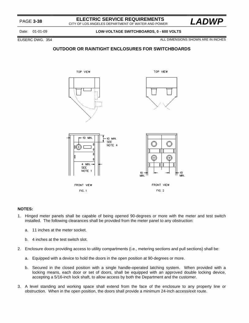
PAGE 3-38 ELECTRIC SERVICE REQUIREMENTS CITY OF LOS ANGELES DEPARTMENT OF WATER AND POWER LADWP
Date: 01-01-09 LOW-VOLTAGE SWITCHBOARDS, 0 - 600 VOLTS
EUSERC DWG. 354 ALL DIMENSIONS SHOWN ARE IN INCHES
OUTDOOR OR RAINTIGHT ENCLOSURES FOR SWITCHBOARDS NOTES:
1. Hinged meter panels shall be capable of being opened 90-degrees or more with the meter and test switch installed. The following clearances shall be provided from the meter panel to any obstruction: a. 11 inches at the meter socket. b. 4 inches at the test switch slot.
2. Enclosure doors providing access to utility compartments (i.e., metering sections and pull sections) shall be: a. Equipped with a device to hold the doors in the open position at 90-degrees or more. b. Secured in the closed position with a single handle-operated latching system. When provided with a
locking means, each door or set of doors, shall be equipped with an approved double locking device, accepting a 5/16-inch lock shaft, to allow access by both the Department and the customer.
3. A level standing and working space shall extend from the face of the enclosure to any property line or
obstruction. When in the open position, the doors shall provide a minimum 24-inch access/exit route.

LADWP ELECTRIC SERVICE REQUIREMENTS CITY OF LOS ANGELES DEPARTMENT OF WATER AND POWER PAGE 3-39
LOW-VOLTAGE SWITCHBOARDS, 0 - 600 VOLTS Date 01-01-08
OUTDOOR OR RAINTIGHT ENCLOSURES FOR SWITCHBOARDS Cont.) 4. Dimension may be reduced if the service section is supplied from cross bussing or bus duct. 5. References:
a. For standard switchboard service sections, see pages 3-12 and 3-14. b. For meter panels, see pages 3-16, 3-18, 411, 3-34 and 3-36. c. For sealing requirements, see page 3-10. d. For meter height requirements, see page 5-10.

PAGE 3-40 ELECTRIC SERVICE REQUIREMENTS CITY OF LOS ANGELES DEPARTMENT OF WATER AND POWER LADWP
Date: 02-01-03 LOW-VOLTAGE SWITCHBOARDS, 0 - 600 VOLTS
EUSERC DWG. 348
TYPICAL SWITCHBOARD TERMINATION ARRANGEMENTS FOR OVERHEAD SUPPLY
SERVICE SECTION SERVICE SECTION WITH CABLE SUPPLY WITH EXTENSTION
AND CABLE SUPPLY
FIGURE 1 FIGURE 2
SERVICE SECTION SERVICE SECTION WITH BUS DUCT SUPPLY WITH BUSSED EXTENSION
FIGURE 3 FIGURE 4 NOTES:
1. Service entrance conductors shall be furnished and installed by the customer from the service head to the switchboard service section.

LADWP ELECTRIC SERVICE REQUIREMENTS CITY OF LOS ANGELES DEPARTMENT OF WATER AND POWER
PAGE 3-41
LOW-VOLTAGE SWITCHBOARDS, 0 - 600 VOLTS Date 02-01-03
TYPICAL SWITCHBOARD TERMINATION ARRANGEMENTS FOR OVERHEAD SUPPLY (Cont.) 2. Cable conductors should enter through the top (preferred point of entry) of the switchboard service section
(figure 1), or through the side or back of a top hat installed above the service section (figure 2) and terminate at the top of the current-transformer bus units. If this is not practical, the conduits may, with Department approval, enter through the side or back (See "alternate feed" in figure 1) in the sealable section above the instrument-transformer compartment - for this type of entry, the top of the conduit shall not be more than three inches from the top of the switchboard service section and the cables shall be installed to prevent turning or misalignment of the current-transformer bus units.
Note: The cables shall not terminate on cross bussing or in any location behind or to the side of the current-transformer mounting area (below the upper bus support bar).
Caution: The number of service entrance conductors permitted is limited at the weatherhead. See SERVICE ENTRANCE CONDUCTORS, page 7-14.
3. Bus duct (figure 3) may enter either through the top of the switchboard service section, or at the side or back in
the sealable section above the instrument-transformer compartment. 4. A bussed top hat extension (figure 4) with cable terminating facilities is required when the Department installs
and terminates the conductors at the switchboard (i.e., typical of Indoor Customer Station installations). Consult the Department regarding extension requirements.
5. Additional references:
a. For switchboard service section requirements, see pages 3-12 and 3-14. b. For sealing requirements, see page 3-10. c. For lifting handle requirements, see page 3-10. d. For service drop and clearance requirements, see page 7-4. e. For busway service head requirements, see pages 3-48. f. For service drop attachment requirements, see page 7-9. g. For service head requirements, see page 7-14.

PAGE 3-42 ELECTRIC SERVICE REQUIREMENTS CITY OF LOS ANGELES DEPARTMENT OF WATER AND POWER LADWP
Date: 02-01-03 LOW-VOLTAGE SWITCHBOARDS, 0 - 600 VOLTS
TYPICAL SWITCHBOARD TERMINATION ARRANGEMENTS FOR UNDERGROUND SUPPLY
SERVICE SECTION SERVICE SECTION WITH PULL SECTION WITH PULL SECTION
800 AMPERES MAXIMUM OVER 800 AMPERES SEE NOTES 2,3,4 AND 6 SEE NOTES 2,3,4 AND 6
FIGURE 1 FIGURE 2
SERVICE SECTION WITH BOTTOM-FEED SEPARATE PULL BOX SERVICE SECTION
800 AMPERES MAXIMUM 2000 AMPERES MAXIMUM
FIGURE 1 FIGURE 2 NOTES:
1. A switchboard pull section (figures 1 and 2), a separate pull box (figure 3), or a bottom-feed service section (figure 4) shall be provided for underground service.
Note: The bottom-feed section may be either a metering section serving a single-customer or a main service disconnect supplying multiple-metering sections.

LADWP ELECTRIC SERVICE REQUIREMENTS CITY OF LOS ANGELES DEPARTMENT OF WATER AND POWER
PAGE 3-43
LOW-VOLTAGE SWITCHBOARDS, 0 - 600 VOLTS Date 02-01-03
TYPICAL SWITCHBOARD TERMINATION ARRANGEMENTS FOR UNDERGROUND SUPPLY (Cont.) 2. Terminating facilities for the Department's service supply conductors shall be provided in all pull sections. 3 Either bus bars or cables may extend from the pull section terminating facilities into the switchboard service
section of switchboards rated up to 800 amperes. Bus bars are required from the pull section into the switchboard service section of switchboards rated above 800 amperes.
4. When the service section is supplied from a pull section, the bus or cable shall enter the side or back of the
sealable section above the instrument-transformer compartment as shown in figures 1 and 2. When the service section is supplied by horizontal cross bussing, the bussing may enter the instrument-transformer compartment in the area behind the current-transformer bus and above the compartment horizontal barrier.
5. When the service section is supplied from a separate pull box as shown in figure 3, the conductors shall enter
either the top (preferred point of entry) of the switchboard service section or through the side or back of a top hat installed above the switchboard service section. If this is not practical, the conduits may, with Department approval, enter through the side or back (alternate feed) in the sealable section above the instrument-transformer compartment - for this type of entry, the top of the conduit shall not be more than 3 inches from the top of the switchboard service section and the customer shall install the conductors to prevent turning or misalignment of the current-transformer bus units.
Note: The cables shall not terminate on cross bussing or in any location behind or to the side of the current transformer mounting area (below the upper bus support bar).
6. References
a. For standard switchboard service (metering) section requirements, see pages 3-12 and 3-14. b. For bottom-feed switchboard service sections, see page 3-44. c. For standard pull section requirements, see page 3-44. d. For non-standard pull section requirements, see page 3-46. e. For pull box requirements, see pages 2-13 and 2-14.

PAGE 3-44 ELECTRIC SERVICE REQUIREMENTS CITY OF LOS ANGELES DEPARTMENT OF WATER AND POWER LADWP
Date: 01-01-07 LOW-VOLTAGE SWITCHBOARDS, 0 - 600 VOLTS
EUSERC DWG. 327 AND 345 ALL DIMENSIONS SHOWN ARE IN INCHES
STANDARD TERMINATING PULL SECTIONS, BOTTOM-ENTRY

LADWP ELECTRIC SERVICE REQUIREMENTS CITY OF LOS ANGELES DEPARTMENT OF WATER AND POWER
PAGE 3-45
LOW-VOLTAGE SWITCHBOARDS, 0 - 600 VOLTS Date 01-01-09
STANDARD TERMINATING PULL SECTIONS, BOTTOM-ENTRY (Cont.)
SWITCHBOARD RATING MINIMUM ACCESS OPENING (AMPERES) DIMENSION (W) - SEE NOTE 3
3-WIRE 4-WIRE 0 - 400 18" 24"
401 - 800 24" 24" 801 - 1200 24" 30"
1201 - 2000 30" 35" 2001 - 3000 35" 42" 3001 - 5000 42" 44"
NOTES:
1. There is no minimum depth dimension specified for the pull section enclosure except that which is required to provide adequate space for conduit entry and maintain the bus and termination clearances.
2. Pull section access cover panels shall be independent of other service equipment and removable without
disturbing adjacent panels; sealable, provided with lifting handles, and limited to 9 square feet in area with a maximum width or length of 5 feet. Brackets or braces, either permanent or removable, used to support or provide for weatherproofing of the removable access cover panels are not permitted.
3. The minimum access opening dimension ("W") is measured between the inside edges of the left and right side
return flanges.
Note: The actual enclosure outside dimension will be larger and will vary between manufacturers. 4. Terminating facilities shall be provided for termination of the Department's service supply conductors.
Note: Terminating facilities shall be supported to prevent misalignment of the current-transformer bus units with the utility cables installed.
5. The shaded area is reserved for the Department's service supply conductors. No conduits or customer wiring
shall terminate in, or be routed through, this area including ground connections. 6. The minimum clearance from any energized part to a removable access cover panel shall be 4 inches. This
dimension may be reduced to 1-1/2 inches if a removable safety barrier is provided by the manufacturer. 7. 3 inch dimension measured from the centerline of the top terminating bolt to any obstruction including the
exterior cover panel. 8. Cross-bussing of a different phase or potential installed behind or below any terminating position shall be fully
insulated or barriered. Insulating barriers shall be a rigid, nonflammable material rated for the serving voltage, resistant to ARC tracking, resistant to puncture or damage by impact, and attached with non-conducting fasteners.
9. Additional references:
a. For typical installation arrangements, see page 3-42. b. For sealing requirements, see page 3-10. c. For lifting handle requirements, see page 3-10. d. For bonding and ground requirements, see page 3-10. e. For cable termination facilities, see page 2-12.

PAGE 3-46 ELECTRIC SERVICE REQUIREMENTS CITY OF LOS ANGELES DEPARTMENT OF WATER AND POWER LADWP
Date: 01-01-09 LOW-VOLTAGE SWITCHBOARDS, 0 - 600 VOLTS
ALL DIMENSIONS SHOWN ARE IN INCHES
NONSTANDARD TERMINATING PULL SECTIONS FOR BELOW GROUND LEVEL INSTALLATIONS (SEE NOTE 1)
SWITCHBOARD RATING MINIMUM ACCESS OPENING DIMENSION - SEE NOTE 3 (AMPERES) PULL SECTION (W1) ENTRANCE WIREWAY (W2)
3-WIRE 4-WIRE 0 - 400 18 24
401 - 800 24 24
18
801 - 1200 24 30 1201 - 2000 30 35
24
NOTES:
1. For the purpose of these requirements, “nonstandard” means that the equipment arrangements represented above are not standard construction and require special ordering from manufacturers.
2. The pull section and entrance wireway access cover panels shall be independent of other service equipment
and removable without disturbing adjacent panels; sealable, provided with lifting handles, and limited to 9 square feet in area with a maximum width or length of 5 feet. Brackets or braces, either permanent or removable, used to support or provide for weatherproofing of the removable access cover panels are not permitted.
3. The minimum access opening dimensions ("W1" and "W2") are measured between the inside edges of the left
and right side return flanges.

LADWP ELECTRIC SERVICE REQUIREMENTS CITY OF LOS ANGELES DEPARTMENT OF WATER AND POWER
PAGE 3-47
LOW-VOLTAGE SWITCHBOARDS, 0 - 600 VOLTS Date 01-01-09
NONSTANDARD TERMINATING PULL SECTIONS (Cont.) 4. For Figure 1 applications the customer must provide the dimension measured from the bottom of the pull
section to the top of the highest supply conduit when ordering the pull section to assure proper termination height.
5. The terminating facilities shall be located as far forward (close to the pull section access cover panels) as
possible to provide for adequate cable bending radius.
Note: The minimum clearance from any energized part to a removable access cover panel shall be 4 inches. This dimension may be reduced to 1-1/2 inches if a removable safety barrier is provided by the manufacturer.
6. The shaded area is reserved for the Department's service supply conductors. No conduits or customer wiring
shall be installed in or routed through this area. No other conductors or ground connections shall be routed through or terminated in this area
7. Cross-bussing of a different phase or potential installed behind or below any terminating position shall be fully
insulated or barriered. Insulating barriers shall be a rigid, nonflammable material rated for the serving voltage, resistant to ARC tracking, resistant to puncture or damage by impact, and attached with non-conducting fasteners.
8. The edges of the cable window between the entrance raceway and the pull section shall be rounded or
otherwise protected to prevent damage to the service supply conductors.
Note: The width of the cable window shall provide direct access to each specified cable terminating position without bending around the window edges.
9. Conduits shall not enter the side of any pull section without the express permission of the Department. Side
entry conduits may require a wide pull section enclosure to assure adequate spacing for cable bending radius. 10. References:
a. For typical installation arrangements, see page 3-42. b. For sealing requirements, see page 3-10. c. For lifting handle requirements, see page 3-10. d. For cable termination facilities requirements, see page 2-12

PAGE 3-48 ELECTRIC SERVICE REQUIREMENTS CITY OF LOS ANGELES DEPARTMENT OF WATER AND POWER LADWP
Date: 02-01-03 LOW-VOLTAGE SWITCHBOARDS, 0 - 600 VOLTS
EUSERC DWG. 349 ALL DIMENSIONS SHOWN ARE IN INCHES
BUSWAY SERVICE HEADS 1∅ 3-WIRE AND 3∅ 4-WIRE and 3-WIRE (See Note 8)
FRONT VIEW
SIDE VIEW
DETAIL A DETAIL B
FIGURE 1
FRONT VIEW SIDE VIEW
DETAIL A DETAIL B
FIGURE 2
TOP VIEW – SERVICE HEAD PERPENDICULAR TO WALL TOP VIEW - SERVICE HEAD PARALLEL TO WALL SEE NOTE 5
FIGURE 3 FIGURE 4

LADWP ELECTRIC SERVICE REQUIREMENTS CITY OF LOS ANGELES DEPARTMENT OF WATER AND POWER
PAGE 3-49
LOW-VOLTAGE SWITCHBOARDS, 0 - 600 VOLTS Date 02-01-03
BUSWAY SERVICE HEADS (Cont.)
DRILLING TERMINAL FOR LANDING TERMINALS (1600 AMPERE TERMINAL SHOWN)
SEE NOTES 1,2 AND 3
FIGURE 3 NOTES: 1. One terminal landing position is required for each 800 amperes of service ampacity or fraction thereof
(i.e., one position for up to 800 amperes, two positions for 801 amperes through 1600 amperes, three positions for 1601 amperes through 2400 amperes, etc.). Each landing position shall consist of two 9/16-inch holes spaced on 1-3/4-inch vertical centers. When multiple landing positions are required, the horizontal spacing between landing positions shall be 2 inches (minimum).
Exception: For Customer Station installations, one terminal landing position is required for each 400 amperes of service capacity.
2. The neutral terminal shall be permanently marked by the manufacturer. 3. For 240/120-volt 3∅ 4-wire delta services, the power leg (“C” ∅) terminal shall be permanently marked orange
in color by the manufacturer. 4. The neutral terminating bus unit clearance to a wall or other obstruction may be reduced to 7 inches. 5. The maximum dimension from the building wall or nearest obstruction to the outer most landing position shall
not exceed 25 inches unless approved by the Department. 6. Service heads shall not be installed with the terminals over any roof or parapet. 7. Service heads with enclosed terminating positions are not permitted. 8. 3∅ 3-wire is not a standard voltage - see page 1-25 for applications and limitations.

PAGE 3-50 ELECTRIC SERVICE REQUIREMENTS CITY OF LOS ANGELES DEPARTMENT OF WATER AND POWER LADWP
Date: 02-01-03 LOW-VOLTAGE SWITCHBOARDS, 0 - 600 VOLTS
THIS PAGE LEFT INTENTIONALLY BLANK

LADWP ELECTRIC SERVICE REQUIREMENTS CITY OF LOS ANGELES DEPARTMENT OF WATER AND POWER
PAGE 4-1
MEDIUM-VOLTAGE SWITCHGEAR, 2400 - 4800 VOLTS Date 01-01-05
CONTENTS PAGE
A. General . . . . . . . . . . . . . . . . . . . . . . . . . . . . . . . . . . . . . . . . . . . . . . . . . . . . . . . . . . . . . . . . . . . . . . . 4-2
B. Manufacturer’s Drawings for Approval . . . . . . . . . . . . . . . . . . . . . . . . . . . . . . . . . . . . . . . . . . . . . . . . 4-2
C. Compartment Barriers . . . . . . . . . . . . . . . . . . . . . . . . . . . . . . . . . . . . . . . . . . . . . . . . . . . . . . . . . . . 4-2
D. Lifting Handles . . . . . . . . . . . . . . . . . . . . . . . . . . . . . . . . . . . . . . . . . . . . . . . . . . . . . . . . . . . . . . . . . 4-2
E. Sealing and Securing Requirements . . . . . . . . . . . . . . . . . . . . . . . . . . . . . . . . . . . . . . . . . . . . . . . . . 4-3
F. Grounding and Bonding . . . . . . . . . . . . . . . . . . . . . . . . . . . . . . . . . . . . . . . . . . . . . . . . . . . . . . . . . . . 4-3
G. Meter Sockets . . . . . . . . . . . . . . . . . . . . . . . . . . . . . . . . . . . . . . . . . . . . . . . . . . . . . . . . . . . . . . . . . . 4-3
H. Service Disconnects . . . . . . . . . . . . . . . . . . . . . . . . . . . . . . . . . . . . . . . . . . . . . . . . . . . . . . . . . . . . . 4-3
I. Weatherproof Enclosures (NEMA 3-R) and Locking Provisions . . . . . . . . . . . . . . . . . . . . . . . . . . . . . 4-4
K. Compartment Labeling . . . . . . . . . . . . . . . . . . . . . . . . . . . . . . . . . . . . . . . . . . . . . . . . . . . . . . . . . . . 4-4
Illustrations:
Metering Enclosure, 2400-4800 Volts . . . . . . . . . . . . . . . . . . . . . . . . . . . . . . . . . . . . . . . . . . . . . . . . . 4-6
Current-Transformer Compartment . . . . . . . . . . . . . . . . . . . . . . . . . . . . . . . . . . . . . . . . . . . . . . . 4-7Voltage-Transformer Compartment . . . . . . . . . . . . . . . . . . . . . . . . . . . . . . . . . . . . . . . . . . . . . . . 4-7Voltage-Transformer Disconnect Switch . . . . . . . . . . . . . . . . . . . . . . . . . . . . . . . . . . . . . . . . . . . 4-8Voltage-Transformer Fuses . . . . . . . . . . . . . . . . . . . . . . . . . . . . . . . . . . . . . . . . . . . . . . . . . . . . . 4-8Compartment Labeling . . . . . . . . . . . . . . . . . . . . . . . . . . . . . . . . . . . . . . . . . . . . . . . . . . . . . . . . 4-8Meter Panels . . . . . . . . . . . . . . . . . . . . . . . . . . . . . . . . . . . . . . . . . . . . . . . . . . . . . . . . . . . . . . . . 4-8Compartment Barriers . . . . . . . . . . . . . . . . . . . . . . . . . . . . . . . . . . . . . . . . . . . . . . . . . . . . . . . . . 4-8Weatherproof Enclosure . . . . . . . . . . . . . . . . . . . . . . . . . . . . . . . . . . . . . . . . . . . . . . . . . . . . . . . 4-8References . . . . . . . . . . . . . . . . . . . . . . . . . . . . . . . . . . . . . . . . . . . . . . . . . . . . . . . . . . . . . . . . 4-8
Hinged Meter Panel . . . . . . . . . . . . . . . . . . . . . . . . . . . . . . . . . . . . . . . . . . . . . . . . . . . . . . . . . . . . . 4-10
Alternate Meter Panel Arrangement . . . . . . . . . . . . . . . . . . . . . . . . . . . . . . . . . . . . . . . . . . . . . . . . . . 4-12
Instrument-Transformers and Mounting Requirements:
Current-Transformers . . . . . . . . . . . . . . . . . . . . . . . . . . . . . . . . . . . . . . . . . . . . . . . . . . . . . . . . . 4-14Current-Transformer Bus Spacing and Mounting Requirements . . . . . . . . . . . . . . . . . . . . . . . . . 4-15Current-Transformer Mounting Base Detail . . . . . . . . . . . . . . . . . . . . . . . . . . . . . . . . . . . . . . . . . 4-16Voltage-Transformer Mounting Rails Detail . . . . . . . . . . . . . . . . . . . . . . . . . . . . . . . . . . . . . . . . . 4-16
Underground Service Terminating Pull Section . . . . . . . . . . . . . . . . . . . . . . . . . . . . . . . . . . . . . . . . . 4-18

PAGE 4-2 ELECTRIC SERVICE REQUIREMENTS CITY OF LOS ANGELES DEPARTMENT OF WATER AND POWER LADWP
Date: 01-01-05 MEDIUM-VOLTAGE SWITCHGEAR, 2400 - 4800 VOLTS
A. GENERAL
1. For services metered at 2400, 4160 and 4800-volts, the customer shall install a metering enclosure as
shown on page 4-6. 2. For services metered above 4800-volts, consult the Customer Station Design Group regarding service and
metering installation requirements. See page 1-4 for office location and telephone numbers.
B. MANUFACTURER'S DRAWINGS FOR APPROVAL
1. Customers are required to consult the Department regarding all new switchboard installations and changes in metering due to load additions or modifications to existing services.
2. A manufacturer’s equipment drawing shall be submitted to the Department before fabricating all switchgear
rated over 600 volts. 3. Approval drawings shall provide the following information:
a. Job Address (not delivery address). b. Manufacturer's contact with telephone and fax number. c. Voltage, ampacity and short-circuit rating information. d. Details of the equipment with panel layout, sectional view layout with dimensions, and meter socket
provisions with appropriate ESR or EUSERC page references. Single-line type drawings are not acceptable.
e. Any other information deemed necessary by the Department for approval of the manufacturer's
drawing.
4. Mail four copies of switchboard drawings to the Customer Station Design Group (Attention: Switchboard Review). See page 1-4 for the office location and telephone number.
C. COMPARTMENT BARRIERS
1. Metering sections and service terminating sections shall be fully enclosed. 2. Where cables or busses pass through compartment walls, through-the -wall bushings with the full-voltage
rating of the switchgear shall be used. 3. Bus ports through the side barriers of the metering section shall be closed with phenolic barriers or
otherwise be arranged to prevent access to the metering sections.
D. LIFTING HANDLES
1. Removable cover panels shall be equipped with a lifting handle. Cover panels in excess of 3 square feet shall require two lifting handles. The handles shall be located so as to provide control and balance while the panel is being removed.
2. Hinged panels shall be equipped with a handle on the side opposite the hinges. 3. Handles shall be sized for full hand grasping, be securely attached to the panel, and be able to withstand
handling stresses of not less than 75 pounds. Folding or hinged handles are not acceptable.

LADWP ELECTRIC SERVICE REQUIREMENTS CITY OF LOS ANGELES DEPARTMENT OF WATER AND POWER
PAGE 4-3
MEDIUM-VOLTAGE SWITCHGEAR, 2400 - 4800 VOLTS Date 01-01-09
E. SEALING REQUIREMENTS
1. Sealable latches, captive stud assemblies, or sealing screws may be used for sealing and shall be installed so as to prevent a sealed cover from being opened or removed without breaking the seal.
2. Non-hinged removable covers shall be sealed with captive stud assemblies on opposite sides of the cover.
Alternate sealing methods may be used if the removable cover is self-supporting with the securing screws and sealing provisions removed.
3. Hinged covers or panels shall be sealed on the side opposite the hinges. 4. Captive stud assemblies shall consist of a 1/4-inch - 20 (minimum) stud, and associated wing nut, each
drilled 0.0635-inch (minimum) for sealing purposes. The stud shall be securely attached so as to not loosen or back out when being fastened.
5. Removable panels or covers requiring sealing shall not be located behind other panels, covers or doors (except raintight enclosure doors).
F. GROUNDING AND BONDING
1. GROUNDING
a. Manufacturers shall not provide a termination lug for the customer’s grounding conductor in any compartment sealed or locked by the Department.
b. The grounding electrode conductor shall not be installed in, or routed through, any compartment
sealed or locked by the Department.
2. BONDING
a. Bus units installed by the manufacturer to provide bonding between equipment sections are permitted in compartments sealed or locked by the Department. Busses shall be installed so as to not obstruct access to Department equipment or create a tripping hazard.
b. Conduit bonding jumpers shall be terminated at the closest available point where the conduit to be
bonded enters an underground terminating enclosure or metering compartment.
G. METER SOCKETS 1. Every new medium-voltage switchgear installation shall be equipped with a meter socket (without bypass
devices and an approved sealing ring. Sockets shall have the jaw arrangement specified for the voltage and phase to be metered. See page 2-5 for socket jaw arrangements.
2. Meter sockets shall be provided with jaws or clips of beryllium copper, be listed by Underwriters
Laboratories (UL) and meet ANSI Standard C12.7. 3. Meter sockets shall be back connected.
H. SERVICE DISCONNECTS
1. The manufacturer shall furnish and install a single service disconnect device, unless otherwise approved by the Department, on the load side of the meter socket (NEW SEQUENCE) which shall control all of, and only, the energy registered by the meter.

PAGE 4-4 ELECTRIC SERVICE REQUIREMENTS CITY OF LOS ANGELES DEPARTMENT OF WATER AND POWER LADWP
Date: 01-01-09 MEDIUM-VOLTAGE SWITCHGEAR, 2400 - 4800 VOLTS
H. SERVICE DISCONNECTS (Cont.)
2. The service disconnect shall be capable of being locked in the open (off) position. Locking provisions shall
be readily identifiable and accept a standard Department padlock having a 5/16-inch lock shaft and a 1-inch locking clearance.
I. WEATHERPROOF ENCLOSURES (NEMA 3-R) AND LOCKING PROVISIONS
1. The metering enclosures (pages 4-6 and 4-12) are shown as weatherproof (NEMA 3R) enclosures with hinged exterior doors. The exterior doors and associated side panels may be omitted for indoor (NEMA 1) installations.
2. Exterior doors shall be:
a. Hinged on the side opposite of the meter door to allow the meter door to open 90-degrees with the Department's meter and test switch installed.
b. Equipped with a single handle-operated latching system equipped with locking provisions to accept a
standard Department padlock (5/16-inch lock shaft and 1-inch locking clearance). c. Equipped with devices to hold the doors in the open position at 90-degrees or more. The devices shall
be permanently attached to either the enclosure or the doors and may be either automatic or manual but shall not require disassembly to operate.
J. COMPARTMENT LABELING
1. The metering enclosure shall be permanently labeled on the exterior of the enclosure to identify the
metered voltage, phase and ampacity rating.
Note: The ampacity rating is the maximum vacuum breaker trip setting or the maximum fuse rating for the main service disconnect device requested by the customer and approved by the Department.
2. Compartments of the metering enclosure shall be permanently labeled with machine engraved laminated
phenolic or equivalent tags. Labels shall have quarter-inch (minimum) white letters and numbers on a red colored background and shall be readily visible and mechanically attached to the face of the following designated compartments and shall read: a. UTILITY-VOLTAGE-TRANSFORMER COMPARTMENT b. UTILITY VOLTAGE-TRANSFORMER FUSE COMPARTMENT c. UTILITY CURRENT-TRANSFORMER COMPARTMENT d. UTILITY METERING COMPARTMENT D. UTILITY SERVICE TERMINATION COMPARTMENT

LADWP ELECTRIC SERVICE REQUIREMENTS CITY OF LOS ANGELES DEPARTMENT OF WATER AND POWER
PAGE 4-5
MEDIUM-VOLTAGE SWITCHGEAR, 2400 - 4800 VOLTS Date 02-01-03
THIS PAGE LEFT INTENTIONALLY BLANK

PAGE 4-6 ELECTRIC SERVICE REQUIREMENTS CITY OF LOS ANGELES DEPARTMENT OF WATER AND POWER LADWP
Date: 01-01-08 MEDIUM-VOLTAGE SWITCHGEAR, 2400 - 4800 VOLTS
EUSERC DWG. 401 ALL DIMENSIONS SHOWN ARE IN INCHES
METERING ENCLOSURE, 2400-4800 VOLTS

LADWP ELECTRIC SERVICE REQUIREMENTS CITY OF LOS ANGELES DEPARTMENT OF WATER AND POWER
PAGE 4-7
MEDIUM-VOLTAGE SWITCHGEAR, 2400 - 4800 VOLTS Date 01-01-09
METERING ENCLOSURE, 2400-4800 VOLTS (Cont.) NOTES:
A. CURRENT-TRANSFORMER COMPARTMENT 1. THE CURRENT-TRANSFORMER COMPARTMENT SHALL NOT BE USED TO TERMINATE THE
DEPARTMENT'S SERVICE SUPPLY CONDUCTORS. 2 The current-transformer bus units shall be drilled and spaced to accept the Department's current
transformers and permit installation and removal of individual transformers without disturbing adjacent transformers. See page 4-14 for instrument-transformers and mounting requirements.
3. Taps to the voltage-transformer disconnect switch shall be made on the line (supply) side of the current
transformers. 4. The center (B∅) current-transformer bus unit shall be continuous and located on the same vertical plane as
the other current-transformer bus units.
Note: A removable link may be used on the center bus in place of a single continuous bus unit. 5. Provide a pulling eye above each current transformer position as shown. 6. Provide a 1” conduit for secondary wiring from the current-transformer compartment as shown. The
conduit shall be on the same side as the meter panel hinges. 7. Ball studs (1/2”-13 threads with insulating covers) for the attachment of safety grounds shall be provided on
the line and load side of the current-transformer (CT) bus units. The studs shall be located not less than 7” from the end of the bus unit and oriented toward the compartment access opening.
8. The ground bus shall extend to either the front left or right sides of the CT compartment and shall be
provided with grounding terminals for use with the ball studs. The terminals shall be two aluminum-bodied mechanical lugs accepting a range of no. 6 through 250 KCMIL conductors and shall be identified with a label reading “SAFETY GROUNDING POINT FOR UTILITY USE ONLY”.
9. The customer shall not make any wiring connections or install any devices in the current-transformer
compartment except for heating elements specified and supplied by the manufacturer.
B. VOLTAGE-TRANSFORMER COMPARTMENT 1. The voltage-transformer compartment cover shall be lockable with a Kirk key interlock system so that, for
personnel safety, the cover cannot be opened without first opening the VT disconnect switch.
Note: When the cover is removable, the cover shall be limited to 9 square feet in area. 2. The width of the voltage-transformer compartment access opening shall permit unobstructed access to the
voltage transformers. 3. A full width and depth insulated barrier shall be provided to isolate the disconnect switch from the voltage
transformer compartment. 4. Mounting rails (Uni-strut P-1000 or equivalent) shall be provided for the installation of the Department's
voltage transformers. The mounting holes in the front rail shall be 9 inches from the voltage-transformer compartment cover. See page 4-16 for voltage-transformer mounting rail details.

PAGE 4-8 ELECTRIC SERVICE REQUIREMENTS CITY OF LOS ANGELES DEPARTMENT OF WATER AND POWER LADWP
Date: 01-01-09 MEDIUM-VOLTAGE SWITCHGEAR, 2400 - 4800 VOLTS
METERING ENCLOSURE, 2400-4800 VOLTS (Cont.) B. VOLTAGE-TRANSFORMER COMPARTMENT (Cont.)
5. Terminals for the voltage-transformer phase connections shall be provided on the load side of the fuse
mounting clips at a minimum height of 18 inches above the top of the voltage-transformer mounting rails. 6. Provide a 1” conduit for secondary wiring from the voltage-transformer compartment as shown. The
conduit shall be on the same side as the meter panel hinges. 7. The customer shall not make any wiring connections or install any devices in the voltage-transformer
compartment except for heating elements specified and supplied by the manufacturer. C. VOLTAGE-TRANSFORMER DISCONNECT SWITCH
1. Manufacturers shall provide a 3-pole, gang-operated disconnect switch to de-energize the voltage
transformers. In the fully open (off) position, the switch shall provide a visible air gap to verify successful disconnect and the disconnect blades shall visibly and automatically ground.
Note: A viewing window shall be provided so that the switch position, open and grounded or closed, may be confirmed.
2. The primary contacts for the voltage-transformer disconnect switch shall be of the blade and jaw design (or
equivalent) to assure continued adequate blade contact. Wiping contact or pressure contact designs are not acceptable.
3. The voltage-transformer disconnect switch cover shall be independent of the VT compartment cover and
shall barrier all energized parts when the voltage-transformer compartment cover is open. 4. The voltage-transformer disconnect switch operating handle shall be lockable in the closed (on) position
using a standard Department padlock (5/16-inch lock shaft and a 1-inch locking clearance). 5. A Kirk key interlocking system shall be provided for the voltage-transformer disconnect switch and the
voltage-transformer compartment cover so that, for personnel safety, the voltage-transformer compartment cannot be entered until the switch is fully opened, visibly grounded and locked in the open position with the interlock system.
Note: The manufacturer shall supply two keys for the interlock system. One key stays in the voltage-transformer disconnect switch and the spare key will be kept by meter engineering.
6. The interlock system shall prevent closing of the voltage-transformer disconnect switch without first closing
and locking the voltage-transformer compartment cover.
D. VOLTAGE-TRANSFORMER FUSES 1. Manufacturers shall provide three fuse holders for mounting indoor current-limiting fuses for the protection
of the voltage transformers (VT). Each fuse holder shall be provided with two mounting clips having a separation of 8-1/2 inches (measured from clip centers) and accepting a fuse ferrule diameter of 1-5/8 inches.
2. The manufacturer shall bus or wire from the VT switch to the fuse holders. 3. The Department shall furnish and install the fuses and wire from the fuse holders to the voltage
transformers.
LADWP ELECTRIC SERVICE REQUIREMENTS CITY OF LOS ANGELES DEPARTMENT OF WATER AND POWER
PAGE 4-9
MEDIUM-VOLTAGE SWITCHGEAR, 2400 - 4800 VOLTS Date 01-01-08
METERING ENCLOSURE, 2400-4800 VOLTS (Cont.) E. METER PANELS
1. The standard meter socket location is in front of the voltage-transformer disconnect switch. For meter
panel details see page 4-10.
2. The alternate meter socket location is on the current-transformer compartment door. For meter panel details and related requirements, see page 4-12.
F. WEATHERPROOF ENCLOSURE
The metering enclosure is shown as a weatherproof (NEMA 3-R) enclosure. The exterior doors and associated side panels are not required for indoor (NEMA 1) installations. See page 4-4 for additional requirements.
G. ADDITIONAL REFERENCES
1. For installation (clearance and access) requirements, see page 5-13. 2. For sealing requirements, see page 4-3. 3. For lifting handle requirements, see page 4-2. 4. For bonding and grounding requirements, see page 4-3 5. For underground terminating pull section requirements, see page 4-18.

PAGE 4-10 ELECTRIC SERVICE REQUIREMENTS CITY OF LOS ANGELES DEPARTMENT OF WATER AND POWER LADWP
Date: 01-01-10 MEDIUM-VOLTAGE SWITCHGEAR, 2400 - 4800 VOLTS
EUSERC DWG. 408 ALL DIMENSIONS SHOWN ARE IN INCHES
HINGED METER PANEL

LADWP ELECTRIC SERVICE REQUIREMENTS CITY OF LOS ANGELES DEPARTMENT OF WATER AND POWER
PAGE 4-11
MEDIUM-VOLTAGE SWITCHGEAR, 2400 - 4800 VOLTS Date 01-01-05
HINGED METER PANEL (Cont.) 2. The panel shall have a handle attached to the side opposite the hinges. The handle shall not be located less
than 1 inch from the meter socket ring. 3. The panel shall be sealable on the side opposite the hinges. 4. The panel shall be hinged and shall permit the panel to open 90-degrees with the meter and test switch
installed. Clevis or removable pin type hinges shall be removable from the top. 5. The panel shall be bonded to the switchboard enclosure with a flexible, braided wire installed across the
hinges. 6. The panel shall support a 25-pound force applied at the unsupported end of the panel when fully opened with a
maximum sag of 1/8 inch. 7. References:
a. For meter panel applications, see page 4-6. b. For meter socket jaw arrangements, see page 2-5. c. For sealing requirements, see page 4-3. d. For lifting handle requirements, see page 4-3.

PAGE 4-12 ELECTRIC SERVICE REQUIREMENTS CITY OF LOS ANGELES DEPARTMENT OF WATER AND POWER LADWP
Date: 01-01-10 MEDIUM-VOLTAGE SWITCHGEAR, 2400 - 4800 VOLTS
EUSERC DWG. 411 ALL DIMENSIONS SHOWN ARE IN INCHES
ALTERNATE METER PANEL ARRANGEMENT

LADWP ELECTRIC SERVICE REQUIREMENTS CITY OF LOS ANGELES DEPARTMENT OF WATER AND POWER
PAGE 4-13
MEDIUM-VOLTAGE SWITCHGEAR, 2400 - 4800 VOLTS Date 02-01-03
ALTERNATE METER PANEL ARRANGEMENT (Cont.) NOTES:
1. The panel shall be a single, full-height door constructed of 12-gauge (minimum) steel and furnished with a meter ring, meter socket, sealing ring and a slotted opening with a removable plate for installation of a test switch. The plate shall be attached to the rear of the panel with screws that do not protrude through the face of the panel. The edges of the plate and the slotted opening shall be smooth to prevent damage to the meter wiring. See page 4-10 for meter socket, test switch cutout and removable plate details.
2. The panel shall be hinged and equipped with a device to hold the panel open at 90-degrees or more. Clevis or
removable pin type hinges shall be removable from the top. 3. The panel shall have a handle attached on the side opposite the hinges. 4. The panel shall be sealable on the side opposite the hinges. 5. The panel shall be bonded to the switchboard enclosure with a flexible, braided wire installed across the
hinges. 6. A barrier shall be provided to isolate the current-transformer compartment from the meter panel. The barrier
shall be hinged and must fully close with the Department's current-transformers installed without the barrier contacting the transformers.
7. A 1-inch conduit for the VT wiring shall be installed on the same side as the meter panel hinges. 8. The alternate meter panel arrangement is shown as a weatherproof enclosure with an exterior door 9. References:
a. For meter socket jaw arrangements, see page 2-5. b. For sealing requirements, see page 4-3. c. For lifting handle requirements, see page 4-2. d. For additional metering enclosure requirements, see page 4-6. e. For weatherproof enclosure requirements, see page 4-4.

PAGE 4-14 ELECTRIC SERVICE REQUIREMENTS CITY OF LOS ANGELES DEPARTMENT OF WATER AND POWER LADWP
Date: 01-01-10 MEDIUM-VOLTAGE SWITCHGEAR, 2400 - 4800 VOLTS
EUSERC DWG. 407 ALL DIMENSIONS SHOWN ARE IN INCHES
INSTRUMENT-TRANSFORMERS AND MOUNTING REQUIREMENTS A. CURRENT TRANSFORMERS
TABLE 1 SWITCHBOARD TERMINAL PADS
RATING (amperes) CT TYPE L L1 H W NO. OF PADS HOLES PER PAD 0-1200 JCM-4 16 15 11-11/16 9-1/2 1 4
1201-2999 JCM-4 16 15 12-3/16 9-1/2 2 4 3000 AND ABOVE JCM-4 16 15 12-7/16 9-1/2 3 6
Note: Current-transformer terminal pads are constructed of 1/4-inch bus and multiple pads are spaced 1/4 inch. Switchgear designs must assure that all of the current-transformer bus units are in contact the current-transformer terminal pads. Removable bus spacers are not permitted.

LADWP ELECTRIC SERVICE REQUIREMENTS CITY OF LOS ANGELES DEPARTMENT OF WATER AND POWER
PAGE 4-15
MEDIUM-VOLTAGE SWITCHGEAR, 2400 - 4800 VOLTS Date 01-01-10
ALL DIMENSIONS SHOWN ARE IN INCHES
INSTRUMENT-TRANSFORMERS AND MOUNTING REQUIREMENTS (Cont.) B. CURRENT-TRANSFORMER BUS SPACING AND MOUNTING REQUIREMENTS
CURRENT-TRANSFORMER COMPARTMENT BUS SPACING DETAIL
TABLE 2 BUS CLEARANCES (inches) SERVICE DISCONNECT
RATING (amperes) “A” “B” “C” “D” 0-1200 7 MIN. 6
1201-2999 7 MIN. 5-1/2 3000 AND ABOVE 8 MIN.
5-1/2
10-1/2 MIN.
1. The current-transformer bus units shall be drilled to accept the current-transformers (CT) specified and shall be provided with 1/2-inch bolts and associated spring washers and nuts for mounting the CTs. The spring washer may be either a cone-type (Belleville) washer or a flat washer with a split ring washer. All parts shall be plated to prevent corrosion.
Note: When conical washers are used, the manufacturer shall provide a readily visible label in the compartment clearly identifying the recommended torque setting for the bolt assemblies used with the washers. The label shall not be installed on removable or hinged access cover panels.
2. The upper and lower current-transformer bus units shall be sized to accept the current-transformers
specified, be vertically aligned and provide for contact by all of the bus units with all of the current-transformer terminal pads.
3. Laminated current-transformer bus units shall be spaced 1/4 inch to accept the specified current-
transformer. Switchgear designs must assure that all of the current-transformer bus units are in contact with the current-transformer terminal pads. Removable bus spacers are not permitted.

PAGE 4-16 ELECTRIC SERVICE REQUIREMENTS CITY OF LOS ANGELES DEPARTMENT OF WATER AND POWER LADWP
Date: 01-01-10 MEDIUM-VOLTAGE SWITCHGEAR, 2400 - 4800 VOLTS
ALL DIMENSIONS SHOWN ARE IN INCHES
INSTRUMENT-TRANSFORMERS AND MOUNTING REQUIREMENTS (Cont.) C. CURRENT-TRANSFORMER MOUNTING BASE DETAIL
ALL HOLES TAPPED 3/8-16
D. VOLTAGE-TRANSFORMER MOUNTING BASE DETAIL

LADWP ELECTRIC SERVICE REQUIREMENTS CITY OF LOS ANGELES DEPARTMENT OF WATER AND POWER
PAGE 4-17
MEDIUM-VOLTAGE SWITCHGEAR, 2400 - 4800 VOLTS Date 02-01-03
THIS PAGE LEFT INTENTIONALLY BLANK

PAGE 4-18 ELECTRIC SERVICE REQUIREMENTS CITY OF LOS ANGELES DEPARTMENT OF WATER AND POWER LADWP
Date: 01-01-10 MEDIUM-VOLTAGE SWITCHGEAR, 2400 - 4800 VOLTS
EUSERC DWG. 418 ALL DIMENSIONS SHOWN ARE IN INCHES
UNDERGROUND SERVICE TERMINATING PULL SECTION 2400-4800 VOLTS, 3∅ 3-WIRE
Minimum bare bus clearances 3-1/2” ∅ to Ground, 5” ∅-∅
NOTES:
1. Consult with the Customer Station Design group regarding termination enclosure details for services exceeding 4800 volts, For office location and telephone numbers, see page 1-4.
2. Pull section cover panels shall be:
a. Independent of other service equipment and removable without disturbing adjacent panels. b. Sealable, provided with lifting handles, be limited to 9 square feet in area with a maximum width or length of
5 feet

LADWP ELECTRIC SERVICE REQUIREMENTS CITY OF LOS ANGELES DEPARTMENT OF WATER AND POWER
PAGE 4-19
GENERAL INFORMATION Date 01-01-09
UNDERGROUND SERVICE TERMINATING PULL SECTION (Cont.)
c. A full height hinged door may be provided in place of removable cover panels. The door shall: (1) Be hinged and equipped with a device to hold the door open at 90-degrees or more. Clevis or
removable pin-type hinges shall be removable from the top. (2) Be sealable and have a handle on the side opposite the hinges.
3. Cable terminating facilities shall be provided for the Department's service supply conductors as follows:
a. One landing position shall be provided for each 400 amperes of service ampacity (i.e., one position for up
to 400 amperes, two positions for 401 through 800 amperes, three positions for 801 through 1200 amperes, etc.).
b. Each landing position shall consist of two 1/2-inch steel bolts complying with page 2-12, Figure 1 (single
position). When multiple landing positions per phase are required, the horizontal spacing between hole positions shall be a minimum of 4 inches to accommodate Department-installed stress cones.
Exception: When approved by the Department, edgewise-terminating facilities may consist of two 9/16-inch holes spaced on 1-3/4-inch vertical centers in place of the studs.
4. Bare bus clearances shall be a minimum of 12 inches from any phase bus to a removable access cover panel.
Note: The clearance to the access cover panel may be reduced to 3-1/2 inches if a full-height hinged door is provided. See note 2.
5. The edge of any bus support, when provided, shall be located a minimum of 1-inch above the centerline of the
top terminating bolts to allow proper seating of the Department’s supply cable lugs. 6. A ball stud (1/2”-13 thread with an insulating cover) for the attachment of safety grounds shall be provided on
each phase termination bus. The ball stud shall be oriented to face the compartment access opening and positioned so that the hot stick and grounding hardware will not cross over phase bus units during the installation process.
7. The ground bus shall extend to either the front left or right sides and shall be provided with grounding terminals
for use with the ball studs. The terminals shall be two aluminum-bodied mechanical lugs accepting a range of no. 6 through 250 KCMIL conductors and shall be identified with a label reading “SAFETY GROUNDING POINT FOR UTILITY USE ONLY”.
8. Provide one piece of uni-strut P-1000 (or equivalent) channel for each set of termination studs. The uni-struts
shall be positioned to allow the supply conductors to be secured to the struts without bending the conductors. 9. The supply conduits shall enter from the bottom and shall be reasonably centered under the terminating
facilities specified in note 3. 10. References:
a. For metering enclosure requirements, see page 4-6. b. For sealing requirements, see page 4-3. c. For lifting handle requirements, see page 4-2. d. For bonding and grounding requirements, see page 4-3.

PAGE 4-20 ELECTRIC SERVICE REQUIREMENTS CITY OF LOS ANGELES DEPARTMENT OF WATER AND POWER LADWP
Date: 02-01-03 MEDIUM-VOLTAGE SWITCHGEAR, 2400 - 4800 VOLTS
THIS PAGE LEFT INTENTIONALLY BLANK

LADWP ELECTRIC SERVICE REQUIREMENTS CITY OF LOS ANGELES DEPARTMENT OF WATER AND POWER
PAGE 5-1
DESIGN AND INSTALLATION GUIDE FOR METER AND SERVICE EQUIPMENT Date 01-01-10
CONTENTS
PAGE
A. Meter Locations . . . . . . . . . . . . . . . . . . . . . . . . . . . . . . . . . . . . . . . . . . . . . . . . . . . . . . . . . . . . . . . . . . . . 5-2
1. Residential Occupancies . . . . . . . . . . . . . . . . . . . . . . . . . . . . . . . . . . . . . . . . . . . . . . . . . . . . . . . . . 5-22. Commercial and Industrial Occupancies . . . . . . . . . . . . . . . . . . . . . . . . . . . . . . . . . . . . . . . . . . . . . 5-23. Added Metering Equipment . . . . . . . . . . . . . . . . . . . . . . . . . . . . . . . . . . . . . . . . . . . . . . . . . . . . . . . 5-24. Unacceptable Metering Locations . . . . . . . . . . . . . . . . . . . . . . . . . . . . . . . . . . . . . . . . . . . . . . . . . . 5-35. Projections into Side Yards . . . . . . . . . . . . . . . . . . . . . . . . . . . . . . . . . . . . . . . . . . . . . . . . . . . . . . . 5-4
B. Identifying Meters in Multi-meter Installations . . . . . . . . . . . . . . . . . . . . . . . . . . . . . . . . . . . . . . . . . . . . 5-4
C. Meter Rooms . . . . . . . . . . . . . . . . . . . . . . . . . . . . . . . . . . . . . . . . . . . . . . . . . . . . . . . . . . . . . . . . . . . . . 5-5
1. Locations . . . . . . . . . . . . . . . . . . . . . . . . . . . . . . . . . . . . . . . . . . . . . . . . . . . . . . . . . . . . . . . . . . . . . 5-52. Access . . . . . . . . . . . . . . . . . . . . . . . . . . . . . . . . . . . . . . . . . . . . . . . . . . . . . . . . . . . . . . . . . . . . . . . . 5-53. Doors . . . . . . . . . . . . . . . . . . . . . . . . . . . . . . . . . . . . . . . . . . . . . . . . . . . . . . . . . . . . . . . . . . . . . . . . 5-54. Locking Provisions . . . . . . . . . . . . . . . . . . . . . . . . . . . . . . . . . . . . . . . . . . . . . . . . . . . . . . . . . . . . . 5-55. Identification . . . . . . . . . . . . . . . . . . . . . . . . . . . . . . . . . . . . . . . . . . . . . . . . . . . . . . . . . . . . . . . . . . . 5-66. Equipment Arrangements . . . . . . . . . . . . . . . . . . . . . . . . . . . . . . . . . . . . . . . . . . . . . . . . . . . . . . . . 5-67. Foreign Equipment . . . . . . . . . . . . . . . . . . . . . . . . . . . . . . . . . . . . . . . . . . . . . . . . . . . . . . . . . . . . . 5-7
D. Meter Heights Working Space and Clearances, 0-600 Volts . . . . . . . . . . . . . . . . . . . . . . . . . . . . . . . . . 5-10
1. Meter Heights . . . . . . . . . . . . . . . . . . . . . . . . . . . . . . . . . . . . . . . . . . . . . . . . . . . . . . . . . . . . . . . . . 5-112. Working Space and Clearances . . . . . . . . . . . . . . . . . . . . . . . . . . . . . . . . . . . . . . . . . . . . . . . . . . . . 5-113. Housekeeping Pads . . . . . . . . . . . . . . . . . . . . . . . . . . . . . . . . . . . . . . . . . . . . . . . . . . . . . . . . . . . . 5-124. Barrier Posts . . . . . . . . . . . . . . . . . . . . . . . . . . . . . . . . . . . . . . . . . . . . . . . . . . . . . . . . . . . . . . . . . . 5-13
E. Meter Heights Working Space and Clearances, 601 Volts and Above . . . . . . . . . . . . . . . . . . . . . . . . .
1. Meter Heights . . . . . . . . . . . . . . . . . . . . . . . . . . . . . . . . . . . . . . . . . . . . . . . . . . . . . . . . . . . . . . . . . 5-142. Working Space and Clearances . . . . . . . . . . . . . . . . . . . . . . . . . . . . . . . . . . . . . . . . . . . . . . . . . . . 5-143. Housekeeping Pads . . . . . . . . . . . . . . . . . . . . . . . . . . . . . . . . . . . . . . . . . . . . . . . . . . . . . . . . . . . . . 5-154. Barrier Posts . . . . . . . . . . . . . . . . . . . . . . . . . . . . . . . . . . . . . . . . . . . . . . . . . . . . . . . . . . . . . . . . . . . . 5-15
F. Meter Cabinets . . . . . . . . . . . . . . . . . . . . . . . . . . . . . . . . . . . . . . . . . . . . . . . . . . . . . . . . . . . . . . . . . . . 5-16
G. Temporary Underground Service Arrangements, Typical . . . . . . . . . . . . . . . . . . . . . . . . . . . . . . . . . . 5-18
H Fiber-Optics Installations . . . . . . . . . . . . . . . . . . . . . . . . . . . . . . . . . . . . . . . . . . . . . . . . . . . . . . . . . . . . 5-20
1. General . . . . . . . . . . . . . . . . . . . . . . . . . . . . . . . . . . . . . . . . . . . . . . . . . . . . . . . . . . . . . . . . . . . . . . . 5-20 2. Conduits . . . . . . . . . . . . . . . . . . . . . . . . . . . . . . . . . . . . . . . . . . . . . . . . . . . . . . . . . . . . . . . . . . . . . . 5-203. Terminating Arrangements . . . . . . . . . . . . . . . . . . . . . . . . . . . . . . . . . . . . . . . . . . . . . . . . . . . . . . . 5-20
I. Hazardous (Explosive Atmosphere) Area Installations . . . . . . . . . . . . . . . . . . . . . . . . . . . . . . . . . . . . . . 5-22
1. General . . . . . . . . . . . . . . . . . . . . . . . . . . . . . . . . . . . . . . . . . . . . . . . . . . . . . . . . . . . . . . . . . . . . . . . 5-222. Service Stations and Other Gasoline Dispensing Locations:
a. Supply Conduits and Service Equipment Locations . . . . . . . . . . . . . . . . . . . . . . . . . . . . . . . . . 5-22b. Hazardous Areas . . . . . . . . . . . . . . . . . . . . . . . . . . . . . . . . . . . . . . . . . . . . . . . . . . . . . . . . . . . . 5-22
3. Methane Gas Hazard Areas . . . . . . . . . . . . . . . . . . . . . . . . . . . . . . . . . . . . . . . . . . . . . . . . . . . . . . . 5-24
4. Typical Equipment Arrangements for Methane Locations . . . . . . . . . . . . . . . . . . . . . . . . . . . . . . . . 5-24

PAGE 5-2 ELECTRIC SERVICE REQUIREMENTS CITY OF LOS ANGELES DEPARTMENT OF WATER AND POWER LADWP
Date: 01-01-09 DESIGN AND INSTALLATION GUIDE FOR METER AND SERVICE EQUIPMENT
A. METER LOCATIONS
1. RESIDENTIAL OCCUPANCIES
a. For single-family residences, metering equipment shall be located to permit meters to be read or tested without entering any building on the premises. Wall-mounted metering equipment shall be mounted on, or recessed in, an exterior building wall.
b. For multiple-occupancy buildings, metering equipment shall be:
(1) Located outdoors to permit meters to be read or tested without entering the building, or
Note: Wall-mounted metering equipment shall be mounted on, or recessed in, an exterior building wall.
(2) Located indoors in approved accessible public areas or meter rooms. See page 5-5 for meter
room requirements. (3) Grouped in a single location unless otherwise approved by the Department.
Note: For buildings over three floors, meters may be located and grouped on every third floor or increment thereof.
2. COMMERCIAL AND INDUSTRIAL OCCUPANCIES
Metering equipment shall be:
a. Located so that the meters may be read or tested without entering the building, or
Note: Wall-mounted metering equipment shall be mounted on, or recessed in, an exterior building wall.
b. Located indoors in approved accessible public areas or meter rooms. See page 5-5 for meter
room requirements. c. Grouped in a single location unless otherwise approved by the department.
Note: For buildings over three floors, meters may be located and grouped on every third floor or increment thereof.
3. ADDED METERING EQUIPMENT
a. Where there is a need to provide additional metering equipment to an existing installation, the
customer shall contact the Department for an approved location. b. Additional equipment will normally be grouped with those meters already in service. Where in the
Department’s judgment this is not practical, an alternate metering location, including in the occupancy served, may be approved.
c. In general, only one meter is allowed for each voltage class of service, except where otherwise
permitted by the Department. Where the customer needs to increase the capacity of an existing facility, the capacity of the service and metering equipment shall be increased as opposed to the installation of additional meter and service equipment.

LADWP ELECTRIC SERVICE REQUIREMENTS CITY OF LOS ANGELES DEPARTMENT OF WATER AND POWER
PAGE 5-3
DESIGN AND INSTALLATION GUIDE FOR METER AND SERVICE EQUIPMENT Date 01-01-07
A. METER LOCATIONS (Cont.)
4. UNACCEPTABLE METER LOCATIONS a. For reasons of safety, maintenance of equipment, and service reliability, meters shall not be permitted:
(1) In any location with less than 3 feet clearance to any walk, alley, or driveway providing access to
a commercial, industrial or multi-family residential premises. (2) In any location with less than 12 inches clearance from a single-family residential driveway. (3) In any location where moisture, corrosive fumes, dust, excessive vibrations (as determined by the
Department) and other conditions which may damage or interfere with the operation of the meter. (4) In any hazardous location as determined by the Department. (5) On any balcony, mezzanine floor, roof, or any basement location unless access is provided with
clear stairways of normal tread and rise. Doorways providing access shall be a minimum of 30 inches wide and 6 feet high.
(6) On any fence or retaining wall. (7) Within any residential occupancy. (8) Within any occupancy not served by the meter. (9) Within any breezeway or carport except by permission of the Department. (10) Directly over any stairway, ramp or steps. (11) Directly over any plumbing fixture (See WORKING SPACE AND CLEARANCES, page 5-10 ). (12) In any rest, bath, toilet, shower, or dressing room, or any room accessed through such areas. (13) In any enclosed show window or one having a bulkhead or raised platform. (14) In any attic or place not in general use. (15) In any projection room. (16) Behind any switchboard having bare and exposed live parts, unless the meter is located at least 5
feet from such parts. (17) In any substation or transformer vault, unless such meter is in an enclosure which is effectively
screened from the high-voltage compartment. (18) In any elevator shaft or hatchway, or in any room containing elevator equipment, unless all such
equipment is guarded and meters are located outside the guarded area. (19) In any location protected by alarm systems. In any location with security gates or doors, guard
dogs, or other security measures unless approved by the Department.

PAGE 5-4 ELECTRIC SERVICE REQUIREMENTS CITY OF LOS ANGELES DEPARTMENT OF WATER AND POWER LADWP
Date: 01-01-09 DESIGN AND INSTALLATION GUIDE FOR METER AND SERVICE EQUIPMENT
A. METER LOCATIONS (Cont.)
4. UNACCEPTABLE METER LOCATIONS (Cont.)
(20) On any mobile home or trailer.
Exceptions (underground service only): (a) Temporary mobile school buildings. (b) Residential mobile homes, which are:
1) Located on individual private lots (not mobile home parks) 2) A minimum of 10 feet wide. 3) Installed on a permanent foundation system which is defined by Title 25 as:
“A foundation system is an assembly of materials constructed below, or partly below grade, not intended to be removed from its installation site, which is designed to support the mobile home and engineered to resist the imposition of external natural forces.” A State HUD form 433(A) must be submitted to the Department as proof of compliance with these requirements.
Note: This requirement does not apply to modular/factory built homes. These types of structures will be served the same as any framed (stick built) home.
(21) In any fenced portion of a freeway that requires the meter to be read or tested from within the
fenced area. (22) In any other location judged unacceptable to the Department.
b. Where metering equipment is not located in a Department approved location, or is no longer accessible because of additions or changes to the premises, the customer shall provide, at the customer’s cost, a new and Department approved service location.
5. PROJECTIONS INTO SIDE YARDS
Permitting agencies may limit the projection of service and metering equipment, or enclosures used to house such equipment, into a side or front yard. The customer must consult with the permitting agency before planning any proposed projections.
B. IDENTIFYING METERS IN MULTI-METER INSTALLATIONS Where a meter does not serve an entire building or premises, the meter socket and its related meter switch shall be clearly and permanently marked by the customer to indicate the occupancy or load served. The following are examples of acceptable permanent markings: 1. Identification plates secured by screws, rivets, or an equivalent secure adhesive. 2. Commercially available decals. 2. Weatherproof paint applied by stencil or legible lettering.

LADWP ELECTRIC SERVICE REQUIREMENTS CITY OF LOS ANGELES DEPARTMENT OF WATER AND POWER
PAGE 5-5
DESIGN AND INSTALLATION GUIDE FOR METER AND SERVICE EQUIPMENT Date 01-01-09
C. METER ROOMS
A meter room is a weatherproof, illuminated room provided by the customer and used to enclose electric service and metering equipment. Meter rooms shall be constructed to meet the following requirements: 1. LOCATIONS
When service is provided from underground electric service supply lines, meter rooms shall be located on a first floor, basement, or garage level having permanent vehicle access.
2. ACCESS a. Meter rooms located on a first floor or basement level shall have access from a door located on the
building exterior wall opening directly into the room or, when approved by the Department, from a door opening directly into the room from a public area or hallway. Where a second access door is provided, the door shall not exit into any occupancy.
b. Meter rooms located on garage levels shall have doors opening directly to the garage or parking area. c. Meter rooms located in basement areas of buildings shall have stairs of normal tread and rise.
3. DOORS a. Entrance to the meter room shall be through a doorway not less than 30 inches wide and 6 feet-6
inches high. b. Doors shall be designed to open outward from the room and be equipped with lever-actuated, safety
hardware. If this is not practical in the Department’s judgment, doors may be permitted to open into the room provided the doors are: (1) Equipped with devices to hold the door in the open position. (2) Located so the doors will not open into the meters or obstruct any required working space. Note: ROLL-UP DOORS AND TOP-HINGED DOORS ARE NOT ACCEPTABLE.
4. LOCKING PROVISIONS a. When the meter room is to be locked, the customer shall install a lock-box in a permanent location on
the meter room door, or in a readily accessible location adjacent to the meter room door. The Department will supply the lock-box.
b. The customer will provide a key for the meter room door lock to be housed in the lock-box before the
electric service will be energized. The key will be used for access by the Department.
5. IDENTIFICATION a. Each meter room door shall be provided with a permanent sign reading “ELECTRIC METER ROOM”.
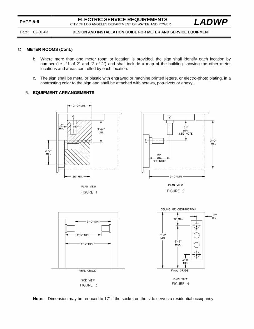
PAGE 5-6 ELECTRIC SERVICE REQUIREMENTS CITY OF LOS ANGELES DEPARTMENT OF WATER AND POWER LADWP
Date: 02-01-03 DESIGN AND INSTALLATION GUIDE FOR METER AND SERVICE EQUIPMENT
C METER ROOMS (Cont.)
b. Where more than one meter room or location is provided, the sign shall identify each location by
number (i.e., “1 of 2” and “2 of 2”) and shall include a map of the building showing the other meter locations and areas controlled by each location.
c. The sign shall be metal or plastic with engraved or machine printed letters, or electro-photo plating, in a
contrasting color to the sign and shall be attached with screws, pop-rivets or epoxy.
6. EQUIPMENT ARRANGEMENTS Note: Dimension may be reduced to 17” if the socket on the side serves a residential occupancy.

LADWP ELECTRIC SERVICE REQUIREMENTS CITY OF LOS ANGELES DEPARTMENT OF WATER AND POWER
PAGE 5-7
DESIGN AND INSTALLATION GUIDE FOR METER AND SERVICE EQUIPMENT Date 01-01-09
C. METER ROOMS (Cont.)
a. A level standing and working space shall be provided in front of service and metering equipment. The
space shall: (1) Be the width of the service and metering equipment but not less than 3 feet. (2) Extend a minimum of 3 feet from the face of the service and metering equipment to any
obstruction. When meter panels are installed facing each other, the working space between the panels shall be a minimum of 4 feet to allow adequate working space with meters installed. See page 5-6 figure 3.
(3) Extend vertically from the standing and working surface to the top of the service and metering
equipment but not less than 6 feet-6 inches.
b. The preferred location for underground terminating enclosures (i.e., pull boxes and pull sections) is on the wall opposite the meter room access door. Where this is not practical, the enclosure may be installed, with Department approval, on a wall perpendicular to the access door. The terminating enclosure shall not be installed on the same wall as the access door except as permitted by the Department for installations with small supply conductors or short cable runs.
UNDERGROUND TERMINATING ENCLOSURE LOCATIONS
FIGURE 1
7. FOREIGN EQUIPMENT a. Cable television, telephone, and other communication installed in the meter room shall not obstruct
working and access clearances to the electric service and metering equipment. b. The meter room shall not be used for storage or warehousing purposes. c. The following equipment shall not be permitted within the meter room:

PAGE 5-8 ELECTRIC SERVICE REQUIREMENTS CITY OF LOS ANGELES DEPARTMENT OF WATER AND POWER LADWP
Date: 01-01-09 DESIGN AND INSTALLATION GUIDE FOR METER AND SERVICE EQUIPMENT
C. METER ROOMS (Cont.)
(1) Gas equipment – including piping. (2) Water heaters or boilers. (3) Security alarm systems connected to the access doors that operate when entry is made to the
meter room. (4) Batteries and battery charging equipment. (5) Any other equipment or facilities judged to be unacceptable by the Department.
NOTE: For additional requirements, see METER LOCATIONS on page 5-2.

LADWP ELECTRIC SERVICE REQUIREMENTS CITY OF LOS ANGELES DEPARTMENT OF WATER AND POWER
PAGE 5-9
DESIGN AND INSTALLATION GUIDE FOR METER AND SERVICE EQUIPMENT Date 02-01-03
THIS PAGE LEFT INTENTIONALLY BLANK

PAGE 5-10 ELECTRIC SERVICE REQUIREMENTS CITY OF LOS ANGELES DEPARTMENT OF WATER AND POWER LADWP
Date: 01-01-09 DESIGN AND INSTALLATION GUIDE FOR METER AND SERVICE EQUIPMENT
D. METER HEIGHTS, WORKING SPACE AND CLEARANCES, 0-600 VOLTS

LADWP ELECTRIC SERVICE REQUIREMENTS CITY OF LOS ANGELES DEPARTMENT OF WATER AND POWER
PAGE 5-11
DESIGN AND INSTALLATION GUIDE FOR METER AND SERVICE EQUIPMENT Date 01-01-09
D. METER HEIGHTS, WORKING SPACE AND CLEARANCES, 0-600 VOLTS (Cont.)
“A” “B” 0” 3-3/4” min.
Greater than 0” to 2” 4-1/4” min. Greater than 2” to 11” 6-1/4” min. Greater than 11” 10” min.
FIGURE 4 1. METER HEIGHTS
The meter height shall not exceed 6 feet-3 inches or be less than 4 feet above the standing and working surface as measured from the centerline of the meter socket. Exception 1: For meters enclosed in a cabinet (Page 5-16) or located in a meter room (Page 5-5), the
minimum meter height may be reduced to 3 feet. Exception 2: For multi-meter panels located on an exterior wall, the minimum meter height may be
reduced to 3 feet as long as at least one meter socket is located at not less than 4 feet. Exception 3: For exposed meter panels (no meter cover) installed on telecom cabinets in public property,
the minimum meter height may be reduced to 3 feet.
2. WORKING SPACE AND CLEARANCES a. A level standing and working space shall be provided in front of service and metering equipment (i.e.,
meter panels and underground terminating enclosures). The working space: (1) Width shall be 3 feet (minimum) but not less than the width of the service and metering
equipment. The space does not need to be centered beneath the meter socket. (2) Depth shall extend 3 feet (minimum) from the face of the service and metering equipment or from
the face of the cabinet used to enclose such equipment. If there are no obstructions from the top of the cabinet to the standing surface (i.e., shelves or ledges) when the cabinet doors are open, the 3 foot measurement may be taken from the face of the service and metering equipment.
Note: Consult the permitting agency regarding additional space requirements when the voltage-to-ground exceeds 150 volts.
(3) Height shall extend 6 feet-6 inches (minimum) from the standing surface but not less than the top
of the service and metering equipment.
b. The level standing and working space shall be located entirely on the property served.

PAGE 5-12 ELECTRIC SERVICE REQUIREMENTS CITY OF LOS ANGELES DEPARTMENT OF WATER AND POWER LADWP
Date: 01-01-10 DESIGN AND INSTALLATION GUIDE FOR METER AND SERVICE EQUIPMENT
D. METER HEIGHTS, WORKING SPACE AND CLEARANCES, 0-600 VOLTS (Cont.)
c. The horizontal clearance from the centerline of the meter to the nearest side wall or other obstruction
shall be a minimum of 10 inches. d. Pull boxes, main service disconnect enclosures and other devices shall be located so they will not
interfere with meter setting or testing. See figure 4. e. Water plumbing fixtures that extend more than 6 inches out from the face of the meter panel must be
located a minimum of 18 inches measured horizontally from the outside edge of the meter panel. f. Gas meters and associated plumbing must be located a minimum of 3 feet measured horizontally from
the edge of the gas meter or associated plumbing fixture to the edge of the meter panel. g. Clearances shall be increased where necessary to permit hinged door or meter panels to be fully
opened. h. Where equipment or access to equipment is located on different sides of a switchboard, a walkway at
least 24 inches in width shall be provided around at least one end of the switchboard.
3. HOUSEKEEPING PADS a. Where indoor (NEMA 1) service and metering equipment is installed within a building on an
elevated portion of the floor (housekeeping pad), the pad shall be flush with or extend a minimum of 3 feet in front of, the service and metering equipment. See Figures 1 and 2.
b. Where indoor (NEMA 1) service and metering equipment or outdoor (NEMA 3R) raintight service
and metering equipment is installed on a housekeeping pad, the pad shall extend a minimum of 3 feet from the face of the raintight enclosure. See Figure 3.
c. Housekeeping pads shall extend the width of the underground terminating enclosure and metering
sections but not less than 3 feet.

LADWP ELECTRIC SERVICE REQUIREMENTS CITY OF LOS ANGELES DEPARTMENT OF WATER AND POWER
PAGE 5-13
DESIGN AND INSTALLATION GUIDE FOR METER AND SERVICE EQUIPMENT Date 01-01-09
D. METER HEIGHTS, WORKING SPACE AND CLEARANCES, 0-600 VOLTS (Cont.)
4. BARRIER POSTS
a. Barrier posts, or other Department approved protection, shall be furnished and installed by the customer when the required working space is exposed to vehicular traffic, hazardous conditions or when otherwise specified by the Department.
Note: Barrier posts are not required for single-family residential services unless, in the Department’s judgment, there are unusual conditions requiring barrier posts.
b. Barrier posts shall be constructed from galvanized pipe (5-inch minimum diameter) installed in a
concrete foundation. The post shall be concrete filled with a concrete cap as shown. c. Barrier posts shall be located so that hinged access doors may open fully and with a maximum spacing
between posts of 4 feet to prevent vehicle contact. The closest surface of the post shall not be less than 3 feet from the face of the service and metering equipment or from the face of the cabinet used to enclose such equipment.
Note: Consult the permitting agency when the voltage-to-ground exceeds 150 volts.

PAGE 5-14 ELECTRIC SERVICE REQUIREMENTS CITY OF LOS ANGELES DEPARTMENT OF WATER AND POWER LADWP
Date: 01-01-09 DESIGN AND INSTALLATION GUIDE FOR METER AND SERVICE EQUIPMENT
E. METER HEIGHTS, WORKING SPACE AND CLEARANCES, 601 VOLTS AND ABOVE
1. METER HEIGHTS
The maximum meter height shall not exceed 6 feet-3 inches or be less than 4 feet as measured from the centerline of the meter socket to the standing and working surface.
Exception: Where a remote meter panel is enclosed in a raintight cabinet or located in a meter room, the minimum meter height may be reduced to 3 feet.
2. WORKING SPACE AND CLEARANCES
a. Switchgear sections shall be provided with a minimum of 5 feet of clear, unobstructed working and standing space in the front of each utility section containing meters and associated equipment (i.e., test switches, current transformers, voltage transformers and fuses) or service supply cable terminating facilities. The width of the working and standing space of each utility section shall be as wide as the section but not less than 3 feet.
b. Since the switchgear design requires access to both the front and rear of the switchgear, a walkway of
not less than 2 feet in width shall be provided around one end of the switchgear. c. The pull section access opening (See Front View on page 4-18) may be oriented to face either the
current-transformer (CT) side, voltage transformer (VT) side or end of the switchgear.

LADWP ELECTRIC SERVICE REQUIREMENTS CITY OF LOS ANGELES DEPARTMENT OF WATER AND POWER
PAGE 5-15
DESIGN AND INSTALLATION GUIDE FOR METER AND SERVICE EQUIPMENT Date 01-01-09
E. METER HEIGHTS, WORKING SPACE AND CLEARANCES, 601 VOLTS AND ABOVE (Cont.)
3. HOUSEKEEPING PADS
a. When indoor, non-raintight (NEMA 1) switchgear is installed on an elevated portion of the floor, or housekeeping pad, the pad shall be either flush with, or extend a minimum of 5 feet in front of, the utility sections. If the pad is flush with the front of the switchgear sections, the maximum meter height of 6 feet-3 inches shall not be exceeded.
b. When outdoor raintight (NEMA 1) switchgear is installed on a housekeeping pad, the pad shall extend
a minimum of five feet in front of the utility sections as measured from the face of the switchgear enclosure.
4. BARRIER POSTS
a. Barrier posts, or other Department approved protection, shall be furnished and installed by the customer when the required working space is exposed to vehicular traffic, hazardous conditions or when otherwise specified by the Department.
b. Barrier posts shall be constructed from galvanized pipe (5-inch minimum diameter) installed in a
concrete foundation. The post shall be concrete filled with a concrete cap as shown on page 5-13. c. Barrier posts shall be located so that hinged access doors may open fully and with a maximum spacing
between posts of 4 feet to prevent vehicle contact. The closest surface of the post shall not be less than 5 feet from the face of the service and metering equipment or from the face of the cabinet used to enclose such equipment.
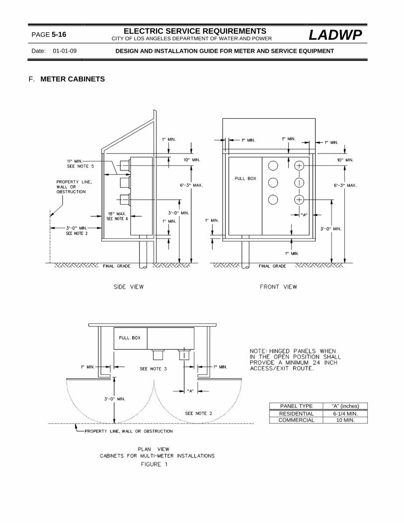
PAGE 5-16 ELECTRIC SERVICE REQUIREMENTS CITY OF LOS ANGELES DEPARTMENT OF WATER AND POWER LADWP
Date: 01-01-09 DESIGN AND INSTALLATION GUIDE FOR METER AND SERVICE EQUIPMENT
F. METER CABINETS
PANEL TYPE “A” (inches) RESIDENTIAL 6-1/4 MIN. COMMERCIAL 10 MIN.

LADWP ELECTRIC SERVICE REQUIREMENTS CITY OF LOS ANGELES DEPARTMENT OF WATER AND POWER
PAGE 5-17
DESIGN AND INSTALLATION GUIDE FOR METER AND SERVICE EQUIPMENT Date 01-01-09
F. METER CABINETS (Cont.)
PANEL TYPE “A” (inches) “B” (inches) “C” (inches) MIN. MAX. MIN. MIN.
RESIDENTIAL 7 10 10 10 COMMERCIAL 11 18 10 10
CABINETS FOR SINGLE-METER INSTALLATIONS
FIGURE 2
1. A meter cabinet or enclosure will be required whenever: a. Indoor (NEMA 1) service and metering equipment is installed in outdoor locations. b. Meters are installed in any school location that is accessible to student traffic. c. Meters are installed in any location where, in the Department’s judgment, moisture, fumes, dust, or
similar deteriorating agents will damage or interfere with the operation of the meter.
2. Meter cabinet doors may be either side-hinged or sliding. Hinged doors shall open a minimum of 90-degrees and when in the open position shall provide a minimum 24 inch access/exit route. Sliding doors shall be individually tracked; be top roller mounted and slide easily.
Note: ROLL-UP DOORS AND TOP-HINGED DOORS ARE NOT ACCEPTABLE. 3. Door jams and vertical posts installed in the cabinet opening shall provide the required clearances for
meters and terminating enclosures. 4. When the meter cabinet is to be locked, the customer shall install either a double locking mechanism or a
lock-box. The lock box shall be in a permanent location on the meter cabinet door, on the meter cabinet, or in a readily accessible location adjacent to the meter cabinet. The Department will supply the lock-box.
Note: For lock box installations, the customer shall provide a key for the meter cabinet door lock to be housed in the lock-box before the electric service will be energized. The key will be used for access by the Department.

PAGE 5-18 ELECTRIC SERVICE REQUIREMENTS CITY OF LOS ANGELES DEPARTMENT OF WATER AND POWER LADWP
Date: 01-01-09 DESIGN AND INSTALLATION GUIDE FOR METER AND SERVICE EQUIPMENT
F. METER CABINETS (Cont.)
5. The minimum clearance may be reduced to 7 inches for residential meter sockets. 6. A level standing and working space shall extend:
(1) 3 feet minimum as measured from the face of the cabinet to the property line or any obstruction.
Note: If there are no obstructions from the top of the cabinet to the standing surface (i.e., shelves or ledges) when the cabinet doors are open, the 3 foot measurement may be taken from the face of the service and metering equipment.
(2) Vertically to a height of 6 feet-6 inches as measured from the standing and working surface.
G. TYPICAL TEMPORARY UNDERGROUND SERVICE ARRANGEMENTS
(200 AMPERES MAXIMUM, 0-600 VOLTS)
TEMPORARY METER POST ARRANGEMENT
1. For underground installations, temporary service arrangements may be supplied from either the underground terminating enclosure (pull box or pull section) for the permanent service or directly from the Department’s electric system. When supplied from the permanent terminating enclosure, the contractor shall provide and install the service entrance conductors from the terminating enclosure to the temporary service pole.
Note: Meter panels provided for temporary power shall not be installed on building interior or exterior walls to avoid conflicts for meter reading access or construction operations.

LADWP ELECTRIC SERVICE REQUIREMENTS CITY OF LOS ANGELES DEPARTMENT OF WATER AND POWER
PAGE 5-19
DESIGN AND INSTALLATION GUIDE FOR METER AND SERVICE EQUIPMENT Date 01-01-09
G. TYPICAL TEMPORARY UNDERGROUND SERVICE ARRANGEMENTS (Cont.)
2. When the customer’s temporary service is supplied directly from the Department’s electric system, the
customer shall install a pull box enclosure for termination of the Department’s service supply conductors. The customer shall provide the conduit and wiring from the pull box to the meter socket panel.
3. A residential meter socket may be used for 100-ampere single-phase services. A safety socket box is
required for 200-ampere single-phase services and for all three-phase services. Service equipment and receptacles must be weatherproof, rated for the load to be served and adequately bonded and grounded.
4. “Piggy-back” meter socket panels that plug into the customer’s permanent meter socket to provide
temporary service are not permitted. 5. References:
a. For working space and clearance requirements, see page 5-10. b. For safety-socket meter panel details, see pages 2-24 and 2-26. c. For engineering offices and phone numbers, see page 1-4. d. For pull box requirements, see page 2-13.

PAGE 5-20 ELECTRIC SERVICE REQUIREMENTS CITY OF LOS ANGELES DEPARTMENT OF WATER AND POWER LADWP
Date: 01-01-09 DESIGN AND INSTALLATION GUIDE FOR METER AND SERVICE EQUIPMENT
H. FIBER-OPTICS INSTALLATIONS
1. GENERAL
Customers shall provide fiber-optics facilities, as specified by the Department, on premises supplied underground with:
a. Commercial or industrial structures of 50 or more tenants. b. Commercial or industrial structures of 100,000 square feet or larger – excluding warehouses, parking
facilities, and other predominately storage oriented facilities. c. Residential multi-tenant complexes of 50 or more units.
Note: The Department may require customers to provide fiber-optics facilities for other installations where, in the Department’s judgment, automated meter reading, demand side management or other automated distribution functions may be used.
2. CONDUITS
a. A conduit for enclosing fiber-optics conductors shall be generally installed as follows: (1) For premises with transformer structures (i.e., transformer pads or vaults), a conduit shall be
installed from the property line to the transformer structure(s) and from the transformer structure(s) to each metering location – where a building or structure has more than one metering location, a fiber-optics conduit is required at only one of the locations.
(2) For premises with indoor transformer rooms, a fiber-optics conduit shall be installed from the
property line to the transformer room. A fiber-optics conduit may also be required from the transformer room to the metering location if the metering location is either (a) in another building or (b) in a location sufficiently remote from the transformer room so that future installation of the conduit, in the Department’s judgment, is impractical.
b. The conduit shall run in the same trench and be the same size as the primary or service conduit
installed in the trench but not less than 4-inches trade size. c. Bending and spacing requirements shall be the same as the electric conduits in the same trench.
3. TERMINATING ARRANGEMENTS a. For service and metering equipment located on outside building walls or within meter rooms,
terminating arrangements for fiber-optics conduits shall be provided as follows: (1) The fiber-optics conduit shall terminate in the bottom center of a pull box, provided by the
customer, measuring a minimum of 12” H x 12” W x 6” D. (2) The pull box shall be mounted a minimum of 4 feet above the floor or standing surface as
measured from the bottom of the box and no other equipment or obstructions shall be installed above the box.
(3) The pull box shall not intrude into the clear working space required in front of the underground
terminating enclosure, metering panels or any other installed equipment.

LADWP ELECTRIC SERVICE REQUIREMENTS CITY OF LOS ANGELES DEPARTMENT OF WATER AND POWER
PAGE 5-21
DESIGN GUIDE FOR METER AND SERVICE EQUIPMENT INSTALLATIONS Date 01-01-09
H. FIBER-OPTICS INSTALLATIONS (Cont.)
(4) A label shall be provided on the pull box cover, by the customer, reading “DEPARTMENT OF
WATER AND POWER, FIBER-OPTICS”. The label shall be constructed of either metal or plastic with engraved or machine printed letters (1/2 inch minimum) and shall be attached with screws, pop-rivets or epoxy.
b. For service and metering equipment provided in freestanding, weatherproof (3R) enclosures
remote from buildings or structures, fiber-optics terminating arrangements shall be provided as follows: (1) The customer shall provide a location for a future fiber-optics pedestal, to be installed by the
Department, on the concrete pad adjacent to the weatherproof enclosure. The location shall accommodate a pedestal with base measuring 24” x 24”.
(2) The pedestal location shall not intrude into the clear working space required in front of the
underground terminating section, metering section, or any other sections with removable or hinged access panels.
(3) The fiber-optics conduit shall terminate in the space provided for the pedestal base and not less
than 2 inches above the concrete pad and not less than 12-inches from the edge of the concrete pad or 9 inches from the switchboard enclosure. The conduit shall be capped and provided with a pull tape.

PAGE 5-22 ELECTRIC SERVICE REQUIREMENTS CITY OF LOS ANGELES DEPARTMENT OF WATER AND POWER LADWP
Date: 01-01-09 DESIGN AND INSTALLATION GUIDE FOR METER AND SERVICE EQUIPMENT
I. HAZARDOUS (EXPLOSIVE ATMOSPHERE) AREA INSTALLATIONS
1. GENERAL
a. Metering equipment and terminating enclosures (i.e., pull boxes and pull sections) used for the
connection of the Department’s service supply conductors shall not be installed in locations that may have ignitable levels of flammable vapors, gases, liquids or fibers present as defined in Sections 500 (division classifications) and 505 (zone classifications) of the latest editions of the City of Los Angeles Electric Code, California Electric Code or the National Electric Code.
Note: The Department often terminates its supply conductors while energized and meters are always tested under energized conditions. Both of these procedures can cause arcing conditions leading to catastrophic results if performed in an explosive atmosphere.
b. The Department utilizes procedures (including duct sealing compounds) in some service installations
to inhibit the intrusion of explosive gases and vapors that may be present in the Department’s underground distribution system into the customer’s underground terminating enclosures. However, the Department’s procedures do not meet the explosive gas mitigation methods approved by the City of Los Angeles Department of Building and Safety (DBS) or other permitting agencies and can not be used to meet the mitigation requirements of the customer’s building permit.
c. It is the customer’s responsibility to identify hazardous locations to the Department’s service planning
office and to design the service and metering facilities to avoid conflict with the Department’s Electric Service Requirements and the applicable City, State or National Electric Codes.
d. Meter and service facilities constructed in explosive atmosphere hazardous areas shall be relocated by
the customer at the customer’s expense to conform to the Department’s requirements as well as the applicable permitting agency’s requirements.
2. SERVICE STATIONS AND OTHER GASOLINE DISPENSING LOCATIONS
a. SUPPLY CONDUITS AND METERING EQUIPMENT LOCATIONS (1) If the service supply conduits do not extend through a defined hazardous area, the
underground terminating enclosure and associated metering section may be installed in an approved location outside of a hazardous area.
(2) If the service supply conduits do extend through a hazardous area, the terminating enclosure
shall be located on the outside of the building and outside of the hazardous area. The terminating enclosure and metering section shall be separate and a sealing fitting provided in the conduit(s) between the sections.
b. HAZARDOUS AREAS
The areas classified as hazardous locations (see figure 1) are identified as follows: (1) The area within an 18 inch radius measured from the outside of the gasoline dispensers and the
area within 18 inches of the ground surface and within a 20 foot radius of the gasoline dispensers as measured from the outside of the dispensers.
(2) The area within 18 inches of the ground surface and within a 5-foot radius from a tight fill
connection and a 10-foot radius from a loose fill connection as measured from each fill pipe provided for underground gasoline storage tanks.

LADWP ELECTRIC SERVICE REQUIREMENTS CITY OF LOS ANGELES DEPARTMENT OF WATER AND POWER
PAGE 5-23
DESIGN AND INSTALLATION GUIDE FOR METER AND SERVICE EQUIPMENT Date 01-01-09
I. HAZARDOUS (EXPLOSIVE ATMOSPHERE) AREA INSTALLATIONS (Cont.)
(3) The area within 18 inches of the ground surface and within a 5 foot radius measured from each
ventilation opening provided for underground gasoline storage tanks. (4) The area below the surface of the hazardous areas identified above (a through c) is considered to
be Class 1, Division 1 (most restrictive). No limit is given for how far the hazardous area extends below the surface.
FIGURE 1

PAGE 5-24 ELECTRIC SERVICE REQUIREMENTS CITY OF LOS ANGELES DEPARTMENT OF WATER AND POWER LADWP
Date: 01-01-10 DESIGN AND INSTALLATION GUIDE FOR METER AND SERVICE EQUIPMENT
I. HAZARDOUS (EXPLOSIVE ATMOSPHERE) AREA INSTALLATIONS (Cont.)
3. METHANE GAS HAZARD AREAS
a. Methane is a naturally occurring volatile gas that may be present in the soil in varying concentrations
throughout the Los Angeles Basin. While a proposed development may be in a known Methane Zone or Methane Buffer Zone, any lot or development site in the Los Angeles area may have methane present and require mitigation measures as required by the City of Los Angeles Methane Ordinance.
b. It is the customer’s responsibility to determine the methane status of any proposed project and to
advise the Department of that status at the time the customer’s plans are submitted for review since the presence of methane will directly affect the service design requirements specified by the Department’s service planning offices.
Note: Site information for the methane status on some lots may be found on the Los Angeles Department of Building and Safety (LADBS) website (www.ladbs.org/) under zoning information.
4. TYPICAL EQUIPMENT ARRANGEMENTS FOR METHANE LOCATIONS
a. While the Department utilizes mitigation procedures (including conduit sealing compounds) in some
service installations to inhibit the possible intrusion of explosive gases and vapors that may be present in the Department’s underground distribution system into the customer’s underground service terminating enclosures, these procedures do not meet the approved explosive gas mitigation methods approved by the LADBS or other permitting agencies and cannot be used to meet the mitigation requirements of the customer’s building permit.
b. Hazardous gas mitigation procedures, when required under the customer’s permit, shall be applied
between the service supply terminating enclosure and the associated metering equipment. Under no circumstances shall customer-owned hardware used to mitigate hazardous gas be installed on or in service supply conduits or underground service terminating enclosures.
c. Service termination enclosure locations:
(1) The Department’s underground service terminating enclosure (i.e., pull box or pull section) shall not be installed within any building or building wall in any methane area, methane boundary area, or other location that requires the installation of explosive gas seals or devices for compliance with the City of Los Angeles Methane Ordinance.
Note: If the methane status of a site changes after the service supply terminating enclosure is installed within a building or building wall and requires the installation of explosive gas seals or devices, the terminating enclosure shall be relocated outside of the building or building wall and the required gas mitigation devices shall be provided between the terminating enclosure and the associated metering sections.
d. Underground service termination enclosures located outside of buildings, or not within building walls,
may be installed as follows: (1) For terminating enclosures installed away from buildings, a “double” switchboard pull section may
be installed to supply metering sections located within the buildings. The utility termination section shall be built in compliance with ESR page 3-44, Figure 1. The customer load wireway section may be sized to meet the customer’s wiring requirements.
Note: A single pull section is not suitable in this application since the customer is not permitted to route the service entrance conductors down through the Department’s dedicated work space or in a location that requires access through the Department’s dedicated work space.

LADWP ELECTRIC SERVICE REQUIREMENTS CITY OF LOS ANGELES DEPARTMENT OF WATER AND POWER
PAGE 5-25
DESIGN AND INSTALLATION GUIDE FOR METER AND SERVICE EQUIPMENT Date 01-01-10
I. HAZARDOUS (EXPLOSIVE ATMOSPHERE) AREA INSTALLATIONS (Cont.)
(2) For terminating sections located on the exterior wall of a building, a single standard pull section
(ESR page 3-44) or pull box (ESR page 2-15 or 2-16) may be used with the service entrance conductors exiting the enclosure above any terminating facilities provided in the enclosure.
Note: Terminating enclosures and their associated supply conduits shall not be recessed within a building wall.

PAGE 5-26 ELECTRIC SERVICE REQUIREMENTS CITY OF LOS ANGELES DEPARTMENT OF WATER AND POWER LADWP
Date: 01-01-10 DESIGN AND INSTALLATION GUIDE FOR METER AND SERVICE EQUIPMENT
THIS PAGE LEFT INTENTIONALLY BLANK

LADWP ELECTRIC SERVICE REQUIREMENTS CITY OF LOS ANGELES DEPARTMENT OF WATER AND POWER
PAGE 6-1
DESIGN AND INSTALLATION GUIDE FOR CONDUIT SYSTEMS ON PRIVATE PROPERTY Date 01-01-10
CONTENTS
PAGE
A. General . . . . . . . . . . . . . . . . . . . . . . . . . . . . . . . . . . . . . . . . . . . . . . . . . . . . . . . . . . . . . . . . . . . . . . . 6-2
B. Jurisdiction . . . . . . . . . . . . . . . . . . . . . . . . . . . . . . . . . . . . . . . . . . . . . . . . . . . . . . . . . . . . . . . . . . . . . . 6-2
C. Excavations . . . . . . . . . . . . . . . . . . . . . . . . . . . . . . . . . . . . . . . . . . . . . . . . . . . . . . . . . . . . . . . . . . . . 6-2
1. Public Property and Easements . . . . . . . . . . . . . . . . . . . . . . . . . . . . . . . . . . . . . . . . . . . . . . . . . 6-22. Permit Requirements . . . . . . . . . . . . . . . . . . . . . . . . . . . . . . . . . . . . . . . . . . . . . . . . . . . . . . . . . . 6-23. Locating and Marking Existing Conduits and Substructures (Dig Alert) . . . . . . . . . . . . . . . . . . . . . 6-2
D. Service Locations and Connections . . . . . . . . . . . . . . . . . . . . . . . . . . . . . . . . . . . . . . . . . . . . . . . . . . 6-2
E. Number and Size of Conduits:
1. Residential Services . . . . . . . . . . . . . . . . . . . . . . . . . . . . . . . . . . . . . . . . . . . . . . . . . . . . . . . . . . 6-32. Commercial and Industrial Services . . . . . . . . . . . . . . . . . . . . . . . . . . . . . . . . . . . . . . . . . . . . . . . 6-3
F. Types of Conduit:
1. Nonmetallic Conduit . . . . . . . . . . . . . . . . . . . . . . . . . . . . . . . . . . . . . . . . . . . . . . . . . . . . . . . . . . 6-32. Metallic Conduit . . . . . . . . . . . . . . . . . . . . . . . . . . . . . . . . . . . . . . . . . . . . . . . . . . . . . . . . . . . . . . 6-4
G. Conduit Depth . . . . . . . . . . . . . . . . . . . . . . . . . . . . . . . . . . . . . . . . . . . . . . . . . . . . . . . . . . . . . . . . . . 6-4
H. Conduit Bends . . . . . . . . . . . . . . . . . . . . . . . . . . . . . . . . . . . . . . . . . . . . . . . . . . . . . . . . . . . . . . . . . 6-4
I. Conduit Spacing . . . . . . . . . . . . . . . . . . . . . . . . . . . . . . . . . . . . . . . . . . . . . . . . . . . . . . . . . . . . . . . . 6-5
J. Concrete Encasement . . . . . . . . . . . . . . . . . . . . . . . . . . . . . . . . . . . . . . . . . . . . . . . . . . . . . . . . . . . . 6-5
K. Conduit Risers:
1. Service Risers . . . . . . . . . . . . . . . . . . . . . . . . . . . . . . . . . . . . . . . . . . . . . . . . . . . . . . . . . . . . . . 6-62. Pole Risers . . . . . . . . . . . . . . . . . . . . . . . . . . . . . . . . . . . . . . . . . . . . . . . . . . . . . . . . . . . . . . . . . 6-6
L. Swabbing and Mandrelling . . . . . . . . . . . . . . . . . . . . . . . . . . . . . . . . . . . . . . . . . . . . . . . . . . . . . . . . 6-6
M. Pull Tape . . . . . . . . . . . . . . . . . . . . . . . . . . . . . . . . . . . . . . . . . . . . . . . . . . . . . . . . . . . . . . . . . . . . . 6-6

PAGE 6-2 ELECTRIC SERVICE REQUIREMENTS CITY OF LOS ANGELES DEPARTMENT OF WATER AND POWER LADWP
Date: 01-01-10 DESIGN AND INSTALLATION GUIDE FOR CONDUIT SYSTEMS ON PRIVATE PROPERTY
A. GENERAL
1. All underground installations shall comply with the Rules of the Department of Water and Power (Department) and these Electric Service Requirements.
2. Whenever an installation does not meet the requirements specified in these service requirements, the
Department will require the customer to make the necessary changes or corrections at the customer's expense.
3. Customer's are required to contact the Department to determine the location of the underground supply
point on the customer's premises and connect the customer-installed conduit to the Department's conduits as specified.
B. JURISDICTION
1. The Department has design and inspection jurisdiction for all structures (i.e., vaults, transformer pads,
maintenance holes, handholes, etc) located on the customer’s premises and used for placement of Department-owned equipment.
2. The Department has design and inspection jurisdiction for all distribution conduits and service supply
(lateral) conduits installed outside of buildings or under buildings under at least 2-inches of concrete and used for the installation of Department-owned conductors.
3. The Department has joint design and inspection jurisdiction with the permitting agency over all distribution
and service supply conduits installed through buildings and used for installation of Department-owned conductors. When installed through the interior of buildings, distribution and service supply conduits shall be encased in a minimum of 2-inches of concrete.
C. EXCAVATIONS
1. PUBLIC PROPERTY AND EASEMENTS Consult the Department for any conduit installation on public property or on Department easements.
2. PERMIT REQUIREMENTS The Department is required to obtain a street excavation permit before starting construction in any public way (i.e., street, road, alley, walk, parkway, or similar dedicated thoroughfare).
3. LOCATING AND MARKING EXISTING CONDUITS AND SUBSTRUCTURES The State of California (Government Code 4216) requires that anyone doing excavation work shall call at least two (2) working days prior to starting the excavation. If you are performing this type of work, call Underground Service Alert (Dig Alert) - see page 2 for telephone numbers.
D. SERVICE LOCATIONS AND CONNECTIONS
1. When a residential lot with an existing single underground service supply conduit is subdivided, the property owner is required to provide a new supply conduit from an underground source designated by the Department to each new lot not supplied by the original supply conduit.
2. When two or more residential buildings are provided on a lot to which a single service supply conduit has
been provided by the owner or former owner, the customer may be required to provide a new conduit from a substructure designated by the Department to each new building.

LADWP ELECTRIC SERVICE REQUIREMENTS CITY OF LOS ANGELES DEPARTMENT OF WATER AND POWER
PAGE 6-3
DESIGN AND INSTALLATION GUIDE FOR CONDUIT SYSTEMS ON PRIVATE PROPERTY Date 01-01-10
D. SERVICE LOCATIONS AND CONNECTIONS (Cont.)
3. No more than one underground service location will be permitted for any premises, except: a. Additional service locations may be permitted if more than one building occupies the premises, and
the wiring layout has been submitted to the Department engineers and approved by them as the most desirable serving arrangement.
b. Additional locations may be required for the Department's operating convenience or necessity.
4. Customers are required to determine the supply point from which the Department will provide service to a premises and shall connect the customer-owned conduits to the Department conduits specified if they are provided.
E. NUMBER AND SIZE OF CONDUITS
1. RESIDENTIAL SERVICES
a. For single-family dwellings, conduits shall be sized as follows:
Service Conduit Length on Private Property Ampacity 0 - 100 feet 101 - 200 feet 0 - 125 2" min. 2-1/2" min.
126 - 400 3" min. 3" min.
Note: Where the length of conduit on private property exceeds 200 feet or where services exceed 400 amperes, consult the Department regarding the number and size of conduits required.
b. For multi-occupancy buildings, consult with the appropriate Department engineering office for conduit
requirements. See ENGINEERING OFFICES, Page 1-4, for locations and telephone numbers. c. In general, a conduit is required for each 400 amperes of service ampacity. The Department may
require the installation of spare conduits for the purpose of maintaining service reliability.
2. COMMERCIAL AND INDUSTRIAL SERVICES
1. Consult with the appropriate Department engineering office for conduit requirements. See ENGINEERING OFFICES, Page 1-4, for locations and telephone numbers.
2. In general, a conduit is required for each 400 amperes of service ampacity. The Department may
require the installation of spare conduits for the purpose of maintaining service reliability. 3. Conduits for fiber-optics applications are generally required for installations requiring that dedicated
transformer facilities be located on the customer's premises. For application and installation requirements, see Page 5-20.
F. TYPES OF CONDUITS
1. NONMETALLIC CONDUITS
a. Conduits listed by the Underwriters Laboratories (UL) as rigid, nonmetallic, underground electrical conduit are acceptable as designated for concrete encasement or direct buried use. Nonmetallic conduits shall not be:

PAGE 6-4 ELECTRIC SERVICE REQUIREMENTS CITY OF LOS ANGELES DEPARTMENT OF WATER AND POWER LADWP
Date: 01-01-10 DESIGN AND INSTALLATION GUIDE FOR CONDUIT SYSTEMS ON PRIVATE PROPERTY
F. TYPES OF CONDUIT (Cont.)
(1) Used in non-compacted filled ground unless encased in concrete with reinforcing bars (rebars) in
the concrete envelope. Four #4 bars shall be placed, one in each corner of the concrete envelope, parallel to the conduit run with a minimum cover of 1-1/2 inches.
(2) Installed in sloping terrain where any 40-foot section of the conduit run exceeds 30-degrees from
horizontal or where otherwise specified by the Department.
b. PVC plastic conduit shall comply with ASTM F-512. Type EB-35 (minimum) conduit is required when the conduit is to be concrete encased. Type DB-120 (minimum) conduit is required when conduit is to be direct buried and for all conduit bends. ABS plastic conduit is not acceptable.
c. Plastic conduit must be labeled and installed so that the label is visible.
d. Plastic conduit joints must be primed and cement welded. Primer shall be tinted and shall comply with
ASTM F656. Cement shall comply with ASTM D2564 (heavy-bodied, medium set). e. Joints must be tightly fitted and butted. Deflections in the conduit run will not be permitted by loose
fitting or forcing of conduit fittings. f. The bottom of trenches shall be level and uniformly graded so as to be smooth and free of rocks so
that conduits will not be damaged when the trench is backfilled. Trenches must be backfilled before the Department will install cable in the conduit.
2. METALLIC CONDUITS
a. Galvanized rigid steel conduit (GRC) may be used under all conditions for low-voltage services.
Intermediate metallic conduit (IMC) may be used as an alternate to GRC for low-voltage services except where exposed to traffic.
b. All metallic conduits shall be hot-dipped galvanized. c. Running-fit type connections are not permitted.
G. CONDUIT DEPTH 1. Conduit runs shall be installed at the following depths as measured from the top of the conduits or concrete
envelope to finished grade: a. Secondary conduits (under 600 volts) - 24 inches in either paved or landscaped areas. b. Primary conduits (over 600 volts) - 24 inches (minimum) in paved areas and 36 inches (minimum) in
landscaped areas.
2. Conduits terminated and capped at the property line shall be installed at a minimum depth of 30 inches as measured from the top of the conduits or concrete envelope to gutter grade.
Exception: When supplied from overhead facilities (pole dips), the minimum depth shall be 36 inches for conduit diameters up to 4 inches and 60 inches for conduit diameters exceeding 4 inches.
3. Changes in depth in any conduit run shall conform to the requirements for bends.

LADWP ELECTRIC SERVICE REQUIREMENTS CITY OF LOS ANGELES DEPARTMENT OF WATER AND POWER
PAGE 6-5
DESIGN AND INSTALLATION GUIDE FOR CONDUIT SYSTEMS ON PRIVATE PROPERTY Date 01-01-10
H. CONDUIT BENDS
1. Conduit bends in horizontal runs of conduit and bends used to rise at the service shall be provided as follows: a. For conduits up to 4 inches: 3 foot minimum radius bends. b. For conduits exceeding 4 inches: 4 foot minimum radius bends.
2. Conduit bends used to rise from underground at pole risers shall be provided as follows unless otherwise specified by the Department: a. For conduits up to 4 inches: 3 foot minimum radius bends. b. For conduits exceeding 4 inches: 5 foot minimum radius bends.
3. Conduit bends used to rise from underground: a. At pole risers shall be of GRC or IMC conduit except where otherwise specified by the Department. b. At the service may be of GRC, IMC, or PVC plastic conduit.
4. Straight lengths of conduit may be cold bent in the trench as follows:
Conduit Size Minimum Bend Radius 2" 12-1/2 feet
3" - 6" 65 feet Note: Heat-treated field bending of plastic
conduit is not permitted. 5. Each run of conduit shall be limited to a maximum of one 45-degree and two 90-degree bends unless
otherwise specified by the Department.
I. CONDUIT SPACING 1. A minimum of 2 inch spacing is required between all electric conduits in any run of conduit. If conduits are
placed on top of each other, conduit spacers or a 2-inch sand layer may be used to provide the required spacing. If conduits are stacked more than two high, conduits spacers are required.
2. Conduit spacers shall be self-supporting without transmitting a vertical force to the conduits, and be
installed with the following intervals:
Duct Size Maximum Spacing 2" 10 feet 3" 8 feet
4" - 6" 6 feet 3. A minimum spacing of 12 inches is required between the electric conduits and other conduits installed
parallel in the trench. Conduits crossing the trench shall maintain a minimum 6-inch spacing to the electric conduit.

PAGE 6-6 ELECTRIC SERVICE REQUIREMENTS CITY OF LOS ANGELES DEPARTMENT OF WATER AND POWER LADWP
Date: 01-01-10 DESIGN AND INSTALLATION GUIDE FOR CONDUIT SYSTEMS ON PRIVATE PROPERTY
J. CONCRETE ENCASEMENT
1. All conduits enclosing 34,500-volt conductors and other conduits, when specified by the Department, shall
be encased in a minimum 3-inch concrete envelope using the Department's concrete mix no. 330-C-1700. Small batches of concrete may be mixed on the job site as follows:
Proportion by Loose Dry Volume Water Strength
(gal. per (28 day) cement Concrete Sand #4 Aggregate cu. yd.) p.s.i.
1 3 5 See Note 1700 Note: Ingredients are to be measured and mixed with an amount of water needed
to produce a workable mixture. Each batch is to be in the machine for not less than two minutes after all the ingredients are in the mixture.
2. A minimum of 2 inches of spacing is required between conduits. 3. Tie and fasten all conduits to prevent floating. Do not encircle conduit with metallic fasteners.
K. CONDUIT RISERS
1. SERVICE RISERS Riser conduits above grade at the service may be either schedule 40 PVC, GRC or IMC.
Exception: Riser conduits exposed to vehicular damage shall be GRC.
2. POLE RISERS a. One 10-foot length of PVC Schedule 80 conduit shall be installed by the customer for each conduit
riser required. b. Riser conduits shall be installed plumb with, and against, the pole in the quadrant specified by the
Department. c. PVC schedule 80 conduit less than 2-1/2 inches shall not be used as riser conduit except to enclose
ground wires.
L. SWABBING AND MANDRELLING 1. Each installed conduit shall be swabbed to remove foreign material. 2. The Department may require that a mandrel be hand-pulled through any conduit installation to ensure that
the conduit is properly installed and clear.
Note: All concrete encased conduits shall be mandrelled. 3. A cylindrical mandrel having an outside diameter of 1/4 inch less than the inside diameter of the conduit will
be supplied by the Department.
M. PULL TAPE 1. A pull tape shall be provided in each completed conduit. The tape shall be secured at both ends and
provided with a minimum of 5 feet of slack.
Note: The Department no longer accepts 1/8-inch polypropylene rope.

LADWP ELECTRIC SERVICE REQUIREMENTS CITY OF LOS ANGELES DEPARTMENT OF WATER AND POWER
PAGE 6-7
DESIGN AND INSTALLATION GUIDE FOR CONDUIT SYSTEMS ON PRIVATE PROPERTY Date 01-01-10
M. PULL TAPE (Cont.)
2. Pull tape shall be a woven multi-fiber polyester ribbon with a minimum width of 3/8-inch. The tape shall be
permanently printed with the rated tensile strength (1250 pounds minimum) and sequential footage markings.
3. The pull tape shall be in one continuous length without any cuts or ties.

PAGE 6-8 ELECTRIC SERVICE REQUIREMENTS CITY OF LOS ANGELES DEPARTMENT OF WATER AND POWER LADWP
Date: 01-01-10 DESIGN AND INSTALLATION GUIDE FOR CONDUIT SYSTEMS ON PRIVATE PROPERTY
THIS PAGE LEFT INTENTIONALLY BLANK

LADWP ELECTRIC SERVICE REQUIREMENTS CITY OF LOS ANGELES DEPARTMENT OF WATER AND POWER
PAGE 7-1
DESIGN AND INSTALLATION GUIDE FOR OVERHEAD SERVICES, 0-600 VOLTS Date 02-01-03
CONTENTS
PAGE
A. General . . . . . . . . . . . . . . . . . . . . . . . . . . . . . . . . . . . . . . . . . . . . . . . . . . . . . . . . . . . . . . . . . . . . 7-2
B. Service Drops . . . . . . . . . . . . . . . . . . . . . . . . . . . . . . . . . . . . . . . . . . . . . . . . . . . . . . . . . . . . . . . . 7-2
1. General . . . . . . . . . . . . . . . . . . . . . . . . . . . . . . . . . . . . . . . . . . . . . . . . . . . . . . . . . . . . . . . . . 7-22. Allowable Length . . . . . . . . . . . . . . . . . . . . . . . . . . . . . . . . . . . . . . . . . . . . . . . . . . . . . . . . . . 7.23. Number of Service Drops . . . . . . . . . . . . . . . . . . . . . . . . . . . . . . . . . . . . . . . . . . . . . . . . . . . . 7-2
C. Service Drop Clearances . . . . . . . . . . . . . . . . . . . . . . . . . . . . . . . . . . . . . . . . . . . . . . . . . . . . . . . 7-4
1. General . . . . . . . . . . . . . . . . . . . . . . . . . . . . . . . . . . . . . . . . . . . . . . . . . . . . . . . . . . . . . . . . . . 7-42. Clearances From Buildings . . . . . . . . . . . . . . . . . . . . . . . . . . . . . . . . . . . . . . . . . . . . . . . . . . . 7-43. Clearances over Walkways, Driveways, and Thoroughfares – Public and Private Property . . . 7-64. Clearances over Swimming Pools . . . . . . . . . . . . . . . . . . . . . . . . . . . . . . . . . . . . . . . . . . . . . . 7-85. Clearances from Signs . . . . . . . . . . . . . . . . . . . . . . . . . . . . . . . . . . . . . . . . . . . . . . . . . . . . . 7-96. Clearances from other Conductors . . . . . . . . . . . . . . . . . . . . . . . . . . . . . . . . . . . . . . . . . . . . . 7-9
D. Service Drop Attachments . . . . . . . . . . . . . . . . . . . . . . . . . . . . . . . . . . . . . . . . . . . . . . . . . . . . . . . 7-9
1. General . . . . . . . . . . . . . . . . . . . . . . . . . . . . . . . . . . . . . . . . . . . . . . . . . . . . . . . . . . . . . . . . . 7-92. Attachment Locations and Clearances . . . . . . . . . . . . . . . . . . . . . . . . . . . . . . . . . . . . . . . . . . 7-103. Typical Methods of Attaching Service drops on Building Walls . . . . . . . . . . . . . . . . . . . . . . . . 7-124. Typical Methods of Attaching service Drops Above Building Roofs . . . . . . . . . . . . . . . . . . . . . 7-13
E. Service Heads . . . . . . . . . . . . . . . . . . . . . . . . . . . . . . . . . . . . . . . . . . . . . . . . . . . . . . . . . . . . . . . 7-14
1. General . . . . . . . . . . . . . . . . . . . . . . . . . . . . . . . . . . . . . . . . . . . . . . . . . . . . . . . . . . . . . . . . . . 7-142. Riser Conduits . . . . . . . . . . . . . . . . . . . . . . . . . . . . . . . . . . . . . . . . . . . . . . . . . . . . . . . . . . . . 7-143. Service Entrance Conductors . . . . . . . . . . . . . . . . . . . . . . . . . . . . . . . . . . . . . . . . . . . . . . . . 7-144. Busway Services . . . . . . . . . . . . . . . . . . . . . . . . . . . . . . . . . . . . . . . . . . . . . . . . . . . . . . . . . . 7-155. Locations . . . . . . . . . . . . . . . . . . . . . . . . . . . . . . . . . . . . . . . . . . . . . . . . . . . . . . . . . . . . . . . . 7-156. Replacement or Additional Service Heads . . . . . . . . . . . . . . . . . . . . . . . . . . . . . . . . . . . . . . . 7-16
F. Structures for Clearance . . . . . . . . . . . . . . . . . . . . . . . . . . . . . . . . . . . . . . . . . . . . . . . . . . . . . . . . 7-16
1. General . . . . . . . . . . . . . . . . . . . . . . . . . . . . . . . . . . . . . . . . . . . . . . . . . . . . . . . . . . . . . . . . . . 7-162. Angle Iron Racks . . . . . . . . . . . . . . . . . . . . . . . . . . . . . . . . . . . . . . . . . . . . . . . . . . . . . . . . . . 7-163. Conduit Attachment Risers and Wood Attachment Risers . . . . . . . . . . . . . . . . . . . . . . . . . . . 7-164. Customer-Owned Service Poles . . . . . . . . . . . . . . . . . . . . . . . . . . . . . . . . . . . . . . . . . . . . . . . 7-16
Illustrations:
Angle Iron Racks . . . . . . . . . . . . . . . . . . . . . . . . . . . . . . . . . . . . . . . . . . . . . . . . . . . . . . . . . . . . . . 7-17
Galvanized Rigid Risers for Service Attachments Above the Roof . . . . . . . . . . . . . . . . . . . . . . . . 7-18
Solid Wood Risers for Service Attachments Above the Roof . . . . . . . . . . . . . . . . . . . . . . . . . . . . . 7-20
Customer-Owned Temporary Service Pole (one year maximum service) . . . . . . . . . . . . . . . . . . . 7-22
Customer-Owned Permanent/Temporary Wood Service Pole . . . . . . . . . . . . . . . . . . . . . . . . . . . . 7-24
Customer-Owned Permanent/Temporary Metal Service Pole . . . . . . . . . . . . . . . . . . . . . . . . . . . . 7-26
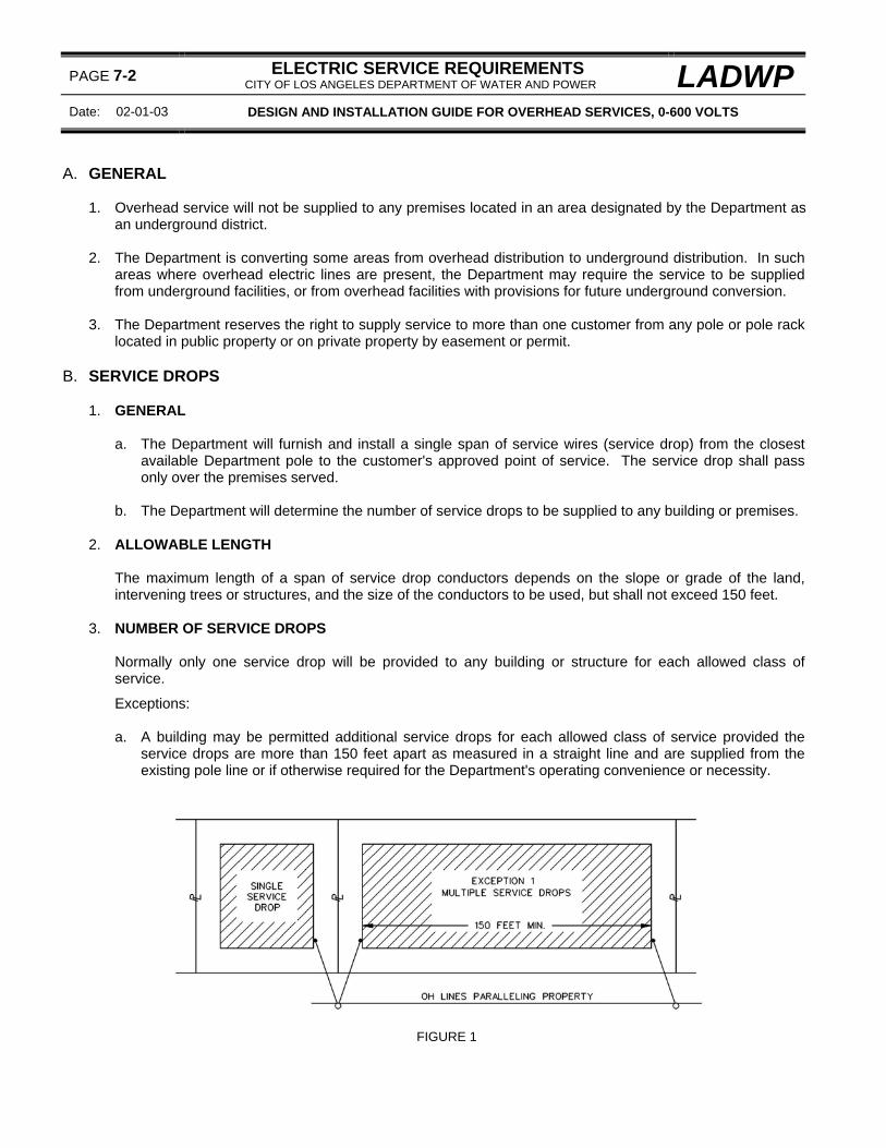
PAGE 7-2 ELECTRIC SERVICE REQUIREMENTS CITY OF LOS ANGELES DEPARTMENT OF WATER AND POWER LADWP
Date: 02-01-03 DESIGN AND INSTALLATION GUIDE FOR OVERHEAD SERVICES, 0-600 VOLTS
A. GENERAL
1. Overhead service will not be supplied to any premises located in an area designated by the Department as an underground district.
2. The Department is converting some areas from overhead distribution to underground distribution. In such
areas where overhead electric lines are present, the Department may require the service to be supplied from underground facilities, or from overhead facilities with provisions for future underground conversion.
3. The Department reserves the right to supply service to more than one customer from any pole or pole rack
located in public property or on private property by easement or permit. B. SERVICE DROPS
1. GENERAL
a. The Department will furnish and install a single span of service wires (service drop) from the closest
available Department pole to the customer's approved point of service. The service drop shall pass only over the premises served.
b. The Department will determine the number of service drops to be supplied to any building or premises.
2. ALLOWABLE LENGTH
The maximum length of a span of service drop conductors depends on the slope or grade of the land, intervening trees or structures, and the size of the conductors to be used, but shall not exceed 150 feet.
3. NUMBER OF SERVICE DROPS
Normally only one service drop will be provided to any building or structure for each allowed class of service.
Exceptions: a. A building may be permitted additional service drops for each allowed class of service provided the
service drops are more than 150 feet apart as measured in a straight line and are supplied from the existing pole line or if otherwise required for the Department's operating convenience or necessity.
FIGURE 1

LADWP ELECTRIC SERVICE REQUIREMENTS CITY OF LOS ANGELES DEPARTMENT OF WATER AND POWER
PAGE 7-3
DESIGN AND INSTALLATION GUIDE FOR OVERHEAD SERVICES, 0-600 VOLTS Date 02-01-03
B. SERVICE DROPS (Cont.)
2. Where a group of residential buildings located on a single lot:
b. Extending up to 150 feet along and facing (paralleling) the pole line supplying service to the lot, a maximum of two service drops may be permitted for each allowed class of service, unless otherwise required for the Department's operating convenience or necessity.
FIGURE 2
c. Extending more than 150 feet along and facing (paralleling) the pole line supplying service to the lot, additional service drops may be permitted for each allowed class of service provided the service drops are more than 150 feet apart as measured in a straight line, or if required for the Department's operating convenience or necessity.
FIGURE 3

PAGE 7-4 ELECTRIC SERVICE REQUIREMENTS CITY OF LOS ANGELES DEPARTMENT OF WATER AND POWER LADWP
Date: 02-01-03 DESIGN AND INSTALLATION GUIDE FOR OVERHEAD SERVICES, 0-600 VOLTS
C. SERVICE DROP CONDUCTOR CLEARANCES 1. GENERAL
a. The minimum clearance for service drop conductors to the ground, structures, and other objects is
specified in General Order 95 (G. O. 95) of the California Public Utilities Commission. Unless otherwise indicated, all clearances specified in this section are based on the use of insulated, abrasion-resistant service drop conductors.
b. Service heads, support structures, and points of attachment shall be located to provide the required
clearances as measured from the lowest point of the service drop, including the drip loop. c When an existing service drop clearance is impaired because of changes made to premises by a
customer, either the owner or tenant, the customer shall provide the means to correct the clearance violation at the customer's cost. If it is necessary for the Department to relocate the service drop to correct the impaired clearances, the customer shall reimburse the Department for the Department's costs.
2. CLEARANCES FROM BUILDINGS
a. Vertical Clearances Above:
Minimum Clearance From Buildings Non-Insulated
Conductors (WP)
Insulated Abrasion Resistant Conductors
(IAR) (1) Building served - All portions of building
including metallic or non-metallic cornice, decorative appendage, eaves, roof or parapet
wall (See page 7-5, fig. 1) . . . . . . . . . . . . . . . 8 feet 1 foot (Note a) (2) Metallic or non-metallic non-walkable* overhang, patio cover or other structure . . . . . 8 feet 1 foot (3) Other buildings on the same premises (See page 7-5, fig.1) . . . . . . . . . . . . . . . . . . . . . . . 8 feet 2 feet (Note b)
Note a Clearance based on a point of attachment within 18 inches of the exterior wall facing the overhead lines from which the service will be supplied and within 30 inches of the roof overhang.
Note b Increase to 8 feet minimum when installed over a
metallic roof with less than a 3/8 rise (Approximately 37 degrees as measured from the horizontal).
* Non-walkable: Those surfaces not normally intended
to support humans such as, but not limited to, handrails, fences, walls, chimneys, parapet walls, cornices, aluminum or lath patio covers and decorative appendages or other light material used for patio covers.
FIGURE 1

LADWP ELECTRIC SERVICE REQUIREMENTS CITY OF LOS ANGELES DEPARTMENT OF WATER AND POWER
PAGE 7-5
DESIGN AND INSTALLATION GUIDE FOR OVERHEAD SERVICES, 0-600 VOLTS Date 02-01-03
C. SERVICE DROP CONDUCTOR CLEARANCES (Cont.)
FIGURE 2
b. Horizontal and Radial Clearances from openable windows, doors, exits, fire escapes, balconies, stairways, walkways. . . . . . . . . . . . . . . . . . . . . . . . . . . . . . . . . . . . . . . . . . . . . . . . . . . 3 feet
FIGURE 3

PAGE 7-6 ELECTRIC SERVICE REQUIREMENTS CITY OF LOS ANGELES DEPARTMENT OF WATER AND POWER LADWP
Date: 01-01-09 DESIGN AND INSTALLATION GUIDE FOR OVERHEAD SERVICES, 0-600 VOLTS
C. SERVICE DROP CONDUCTOR CLEARANCES (Cont.)
3. CLEARANCES OVER WALKWAYS, DRIVEWAYS, AND THOROUGHFARES - PUBLIC AND PRIVATE PROPERTY Vertical clearances above ground for service drops crossing over public and private thoroughfares, driveways and properties shall conform to the following minimum clearances - Conductors:
Condition Minimum
Clearance a. Crossing areas which are accessible only to pedestrians on all premises . . . . . . . 10 feet
b. Crossing over private driveways or other areas accessible to vehicles on:
(1) Residential Premises . . . . . . . . . . . . . . . . . . . . . . . . . . . . . . . . . . . . . . . . . . 12 feet
(2) Commercial or industrial premises . . . . . . . . . . . . . . . . . . . . . . . . . . . . . . . . 16 feet
c. Crossing premises accessible to agricultural equipment . . . . . . . . . . . . . . . . . . . . 15 feet
d. Crossing public thoroughfares . . . . . . . . . . . . . . . . . . . . . . . . . . . . . . . . . . . . . . . . 18 feet This clearance may grade from 18 feet at a position of not more than 12 feet from the curb line to a minimum clearance at the curb line of . . . . . . . . . . . . . . . . . . . . 16 feet
Note: If no curb exists, the outer limits of possible vehicular traffic may be used as the "curb line".
e. Crossing over, or in proximity to, swimming pools, diving boards, platforms, or slides . . . . . . . . . . . . . . . . . . . . . . . . . . . . . . . . . . . . . . . . . . . . . . . . See page 7-8 f. Crossing railroad tracks:
(1) Without overhead trolley wires . . . . . . . . . . . . . . . . . . . . . . . . . . . . . . . . . . . . . . 25 feet
(2) Operated with overhead trolley wires . . . . . . . . . . . . . . . . . . . . . . . . . . . . . . . . . . 26 feet
Note: In all cases, the service drop conductors shall
clear trolley wires by not less than 4 feet.

LADWP ELECTRIC SERVICE REQUIREMENTS CITY OF LOS ANGELES DEPARTMENT OF WATER AND POWER
PAGE 7-7
DESIGN AND INSTALLATION GUIDE FOR OVERHEAD SERVICES, 0-600 VOLTS Date 02-01-03
C. SERVICE DROP CONDUCTOR CLEARANCES (Cont.)
SERVICE DROP CLEARANCES FOR RESIDENTIAL PREMISES
FIGURE 1
SERVICE DROP CLEARANCES FOR COMMERCIAL AND INDUSTRIAL SERVICES
FIGURE 2

PAGE 7-8 ELECTRIC SERVICE REQUIREMENTS CITY OF LOS ANGELES DEPARTMENT OF WATER AND POWER LADWP
Date: 02-01-03 DESIGN AND INSTALLATION GUIDE FOR OVERHEAD SERVICES, 0-600 VOLTS
C. SERVICE DROP CONDUCTOR CLEARANCES (Cont.)
4. CLEARANCES OVER SWIMMING POOLS The installation of swimming pools under existing service drops should be avoided where practical. However, where a swimming pool must be located under existing service drop conductors, the clearances shown in Figure 1 below are required by General Order 95 (California Rules for Overhead Line Construction)
DETAIL A DETAIL B MINIMUM CLEARANCE FOR OPEN-WIRE DROPS MINIMUM CLEARANCE FOR DROPS WIT SPECIALLY APPROVED COVERING (0 – 300 VOLTS)
1. TRIPLEX SERVICE CABLE. 2. ABRASION-RESISTANT CABLES HAVING A
GROUNDED METALLIC SHEATH (ARMORED SERVICE CABLE).
SECTION VIEW PLAN VIEW
DETAIL C
MINIMUM CLEARANCE FOR DROPS ABOVE OR ADJACENT TO DIVING BOARDS AND PLATFORMS
FIGURE 1

LADWP ELECTRIC SERVICE REQUIREMENTS CITY OF LOS ANGELES DEPARTMENT OF WATER AND POWER
PAGE 7-9
DESIGN AND INSTALLATION GUIDE FOR OVERHEAD SERVICES, 0-600 VOLTS Date 02-01-03
C. SERVICE DROP CONDUCTOR CLEARANCES (Cont.)
5. CLEARANCES FROM SIGNS The vertical and horizontal service drop clearance conductor from signs, whether mounted on buildings or isolated structures shall not be less than the following minimum clearances:
Condition Minimum
Clearance a. Vertical clearance above signs without walkable surfaces . . . . . . . . . . . . . . . . . . . . 2 feet b. Vertical clearance above surfaces of signs upon which persons might walk . . . . . . 8 feet c. Vertical clearance under signs that are (1) Illuminated . . . . . . . . . . . . . . . . . . . . . . . . . . . . . . . . . . . . . . . . . . . . . . . . . . . 2 feet (2) Non-illuminated . . . . . . . . . . . . . . . . . . . . . . . . . . . . . . . . . . . . . . . . . . . . . . . 1 foot d. Horizontal clearance from signs which are: (1) Illuminated . . . . . . . . . . . . . . . . . . . . . . . . . . . . . . . . . . . . . . . . . . . . . . . . . . . 3 feet (2) Non-illuminated . . . . . . . . . . . . . . . . . . . . . . . . . . . . . . . . . . . . . . . . . . . . . . . 1 foot
6. CLEARANCES FROM OTHER CONDUCTORS Service drop conductor clearance from telephone and CATV service drop conductors at crossings, and radially where approaching crossings, shall not be less than 2 feet
Exception: This clearance may be reduced to 1 foot within 15 feet of the point of attachment on the building or structure. For additional information, see Attachment Locations and Clearances on page 7-10 and Conduit Risers and Wood Attachment Risers on pages 7-16, 7-18 and 7-20.
D. SERVICE DROP ATTACHMENTS
1. GENERAL
a. On request, a Department service planner will provide assistance in determining a location for the service drop attachment to provide the required clearance for the Department's service drop conductors. See page 1-4 for service planning office locations and telephone numbers.
b. The Department will normally furnish and install standard wire holders (brackets) except as follows:
(1) The customer shall install standard brackets supplied by the Department on buildings constructed
of concrete, brick, wood, or finished stucco. (2) The customer will furnish and install any special brackets, racks, or structures required by the
Department.
c. Attachment brackets shall be installed using through bolts or lag screws as specified by the Department.

PAGE 7-10 ELECTRIC SERVICE REQUIREMENTS CITY OF LOS ANGELES DEPARTMENT OF WATER AND POWER LADWP
Date: 02-01-03 DESIGN AND INSTALLATION GUIDE FOR OVERHEAD SERVICES, 0-600 VOLTS
D. SERVICE DROP ATTACHMENTS (Cont.)
2. ATTACHMENT LOCATIONS AND CLEARANCES
SERVICE DROP ATTACHMENT ON BUILDING SERVICE DROP ATTACHMENT WALL NEAREST TO OVERHEAD LINES ABOVE BUILDING ROOF
FIGURE 1 FIGURE 2
ATTACHMENT ABOVE SHED TYPE STRUCTURE ATTACHMENT ABOVE PATIO COVER
FIGURE 3 FIGURE 4
a. The service drop point of attachment shall normally be located on that portion of a building or structure facing and nearest the street, alley, easement or public way on which the Department’s pole is located. Attachments shall be installed at a height not less than specified in these requirements to permit service drops to be: (1) Installed and maintained in accordance with vertical, horizontal and radial clearances required
above ground and from roofs, obstructions, windows, doorways, openings, balconies, fire escapes swimming pools and other conductors.
(2) Run free from trees, structures, poles, masts, antennas, vents, flood lights or other obstructions.

LADWP ELECTRIC SERVICE REQUIREMENTS CITY OF LOS ANGELES DEPARTMENT OF WATER AND POWER
PAGE 7-11
DESIGN AND INSTALLATION GUIDE FOR OVERHEAD SERVICES, 0-600 VOLTS Date 02-01-03
D. SERVICE DROP ATTACHMENTS (Cont.)
(3) Installed at a location where the weatherhead and point of attachment are safely accessible from a ladder placed on the ground. In general, enough space to provide a "4-to-1" vertical rise is required. When proposed locations will not provide the needed space, consult the appropriate Department service planning office before installing any service equipment or riser conduit.
(4) Attached at only one point on the building and without intermediate support. (5) Arranged so as to not hamper or endanger workmen and firemen in the performance of their
duties.
b. The maximum height of the point of attachment is determined by the service head height. For maximum service head height, see page 7-14.
c. The point of attachment shall be located in either of the following locations:
(1) On the wall nearest to and facing the overhead electric lines from which service will be supplied or
on an adjoining wall within 18 inches of the wall nearest to the overhead lines from which service is to be supplied and where the service drop crosses no intervening part of the structure (See Figure 1).
(2) Above the roof on attachment riser or support structure and located:
(a) Within 18 inches of the wall nearest to and facing the overhead electric lines from which
service is to be supplied and within 30 inches from the edge of the roof overhang and where the service drop crosses no intervening part of the structure (See Figure 2).
(b) Within 18 inches of the side wall adjacent to the wall nearest and facing the overhead electric
lines from which service will be supplied and within 30 inches of the roof overhang but no further back than the highest point of the roof and where the service drop crosses no intervening part of the structure (See Figure 2).
Caution: For points of attachment located above the roof, consult with the Department of Building and Safety where the service drop conductor length over the roof will exceed 4 feet.

PAGE 7-12 ELECTRIC SERVICE REQUIREMENTS CITY OF LOS ANGELES DEPARTMENT OF WATER AND POWER LADWP
Date: 01-01-07 DESIGN AND INSTALLATION GUIDE FOR OVERHEAD SERVICES, 0-600 VOLTS
D. SERVICE DROP ATTACHMENTS (Cont.)
3. TYPICAL METHODS OF ATTACHING SERVICE DROPS ON BUILDING WALLS
FIGURE 1 FIGURE 2
FIGURE 3
a. Clearance from the attachment bracket to the service head shall not be less than 12 inches for a single-spool bracket or 16 inches for a three-spool bracket (measured from center spool) or a maximum of 30 inches.
b. For additional service drop clearance requirements, see page 7-4.

LADWP ELECTRIC SERVICE REQUIREMENTS CITY OF LOS ANGELES DEPARTMENT OF WATER AND POWER
PAGE 7-13
DESIGN AND INSTALLATION GUIDE FOR OVERHEAD SERVICES, 0-600 VOLTS Date 01-01-07
D. SERVICE DROP ATTACHMENTS (Cont.)
4. TYPICAL METHODS OF ATTACHING SERVICE DROPS ABOVE BUILDING ROOFS
SEE PAGE 116 FOR ANGLE IRON SEE PAGE 118 FOR CONDUIT SUPPORT DETAILS ATTACHMENT RISER DETAILS
FIGURE 1 FIGURE 2
SEE PAGE 118 FOR SOLID WOOD ATTACHMENT RISER DETAILS
FIGURE 3
a. Clearance from the attachment bracket to the service head shall not be less than 12 inches for a single-spool bracket or 16 inches for a three-spool bracket (measured from center spool) or a maximum of 30 inches.
b. References:
(1) For additional service drop clearance requirements, see page 7-3. (2) For angle iron support details, see page 7-17. (3) For conduit attachment riser support details, see page 7-18. (4) For solid wood attachment riser details, see page 7-20.

PAGE 7-14 ELECTRIC SERVICE REQUIREMENTS CITY OF LOS ANGELES DEPARTMENT OF WATER AND POWER LADWP
Date: 02-01-03 DESIGN AND INSTALLATION GUIDE FOR OVERHEAD SERVICES, 0-600 VOLTS
E. SERVICE HEADS
1. GENERAL
a. All service heads shall be located as required by the Department but not more than 25 feet above the ground directly below the service head.
b. Service heads for the same class and voltage shall be grouped together and spaced not less than 9
inches or more than 18 inches apart unless otherwise required for Department convenience. c. Service heads for totalized services shall be separated by not less than 18 inches or more than 36
inches. d. Service heads of different classes served from the same pole shall be located as close together as
practical. e. Service heads shall not be located more than 30 inches or less than 12 inches from a single-spool
attachment bracket or 16 inches for a three-spool bracket (measured from center spool), except where otherwise specified by the Department.
2. RISER CONDUITS
a. Conduit attachment risers shall be constructed of galvanized rigid conduit. For all other riser conduits, consult permitting agency.
b. In general, the service raceway conduit shall be continuous and free of junction boxes and condulets.
Exceptions: (1) In single-meter installations, a wireway or condulet may be permitted if the run of riser conduit has
excessive length or bends making a continuous run of conduit impractical. Consult with the Department and the appropriate permitting agency before installing any service equipment.
(2) In multi-meter installations, a sealable, bussed wireway is permitted to serve individual meter
enclosures.
Note: When permitted, junction boxes and wireways shall be sealable and installed in locations that are readily visible for perpetual inspection by the Department.
3. SERVICE ENTRANCE CONDUCTORS
a. The number of service entrance conductors in a riser conduit shall not exceed two conductors per
phase and paralleled service entrance conductors shall not be less than 1/0 AWG.
Note: Each run of conductors in a riser conduit shall enclose a complete circuit (i.e., all phase conductors and the associated neutral conductor).
b. The total number of service entrance conductors at a service head shall not exceed (a) six conductors
per service head for a three-wire service or (b) eight conductors per service head for a four-wire service.
c. The total number of service entrance conductors at a location for each voltage class of service shall not
exceed (a) nine conductors for a three-wire service, or (b) twelve conductors for a four-wire service.
Note: This limitation allows for a maximum "3-to-1" splice between the service entrance conductors and the service drop conductors at the service head.

LADWP ELECTRIC SERVICE REQUIREMENTS CITY OF LOS ANGELES DEPARTMENT OF WATER AND POWER
PAGE 7-15
DESIGN AND INSTALLATION GUIDE FOR OVERHEAD SERVICES, 0-600 VOLTS Date 02-01-03
E. SERVICE HEADS (Cont.)
d. Service entrance conductors shall extend a minimum of three feet beyond the service head unless
otherwise specified by the Department. Spliced sections shall not be used to extend the length of the required tails.
e. The Department shall make connection at the service head between the service drop conductors and
the customer's service entrance conductors. f. Aluminum service entrance conductors shall be wire brushed and coated with an oxide inhibitor before
terminating.
4. BUSWAY SERVICES A busway service shall be required if the service entrance conductors exceed the number per location or size limits - see Service Entrance Conductors above. See page 3-48 for busway service head requirements.
5. LOCATIONS a. Customers shall locate and install service heads as specified by the Department. b. Service heads shall be located in either of the following locations:
(1) On the exterior wall nearest to the overhead electric lines from which the service will be supplied,
or on an adjoining wall adjacent to the attachment bracket. For attachment bracket locations and bracket to service head clearance requirements, see page 7-9.
(2) Above the roof within 18 inches of the exterior wall nearest to the electric lines from which the
service will be supplied and within 30 inches of the roof overhang.
Note: The service head shall generally be installed on the wall or above the roof in the area immediately above the meter. Where the proposed meter location will require a horizontal run of riser conduit to the service head, consult with the permitting agency before installing any service equipment.
c. Service heads shall not be located:
(1) More than 25 feet vertically above the final exterior grade level directly below the service head. (2) On any wall with less than two feet from any common property line common to an adjacent
property.
Note: All locations must provide adequate space for safely climbing a ladder to access the service head. In general a 4-to-1 rise is required. When proposed locations will not provide the allowable space, consult the Department before installing any service equipment.
d. Service heads supplied at the same class of service shall be grouped together and separated by not
less than 9 inches or more than 18 inches. e. Service heads for different classes of service supplied from the same pole shall be located as close
together as practical. f. Service heads for separate services that are totalized shall be separated by not less than 18 inches or
more than 36 inches.

PAGE 7-16 ELECTRIC SERVICE REQUIREMENTS CITY OF LOS ANGELES DEPARTMENT OF WATER AND POWER LADWP
Date: 02-01-03 DESIGN AND INSTALLATION GUIDE FOR OVERHEAD SERVICES, 0-600 VOLTS
E. SERVICE HEADS (Cont.)
6. REPLACEMENT OR ADDITIONAL SERVICE HEADS No service head shall be replaced or additional service heads installed for connection to existing service drops without prior approval of the Department.
F. STRUCTURES FOR CLEARANCE 1. GENERAL
a. Where a structure is necessary to maintain required service drop clearances, the structure shall be
installed and maintained by the customer. The structure shall be located on the building served. b. While the Department approves support structures, the customer must consult with the appropriate
permitting agency regarding structural details and requirements. c. Attachment brackets for communication (i.e., telephone, CATV) service drops shall not be installed on
any electric service drop riser conduit, riser support or in any location, which obstructs access to the Department’s attachment bracket, associated service head(s) or the area between the bracket and the service head(s).
2. ANGLE IRON RACKS
a. An iron angle rack may be installed in above the roof installations to provide the required service drop
conductor clearances. b. For angle iron rack construction details, see page 7-17.
3. CONDUIT ATTACHMENT RISERS AND WOOD ATTACHMENT RISERS a. Conduit attachment (periscope service) risers or solid wood attachment risers shall be required on all
above-roof installations. b. Wood attachment risers shall be constructed of a single piece of solid wood - risers that are laminated,
or constructed of separate pieces, are not permitted. c. Risers to which service drop conductors are attached shall be sufficiently supported to withstand the
stresses imposed by the service drop conductors. d. For construction details of conduit attachment risers see Page 7-18 and for solid-wood attachment
risers see Page 7-20.
4. CUSTOMER SERVICE POLES For construction details for customer-owned service poles, see: a. Page 7-22 for temporary wood poles limited to a maximum one year service. b. Page 7-24 for permanent or temporary wood poles. c. Page 7-26 for permanent or temporary metal poles.

LADWP ELECTRIC SERVICE REQUIREMENTS CITY OF LOS ANGELES DEPARTMENT OF WATER AND POWER
PAGE 7-17
DESIGN AND INSTALLATION GUIDE FOR OVERHEAD SERVICES, 0-600 VOLTS Date 02-01-03
ALL DIMENSIONS SHOWN IN INCHES
ANGLE IRON RACKS
ANGLE IRON SIZE (H) EXTENSION MAXIMUM SIZE OF SERVICE MAXIMUM LENGTH ABOVE ROOF ENTRANCE CONDUCTORS OF SERVICE DROP (FEET)
1-1/4" x 1-1/4" x 1/8" 0" - 30" # 1 AWG 100 1-1/4" x 1-1/4" x 3/16" 31" - 60" # 1 AWG 100 1-1/4" x 1-1/4" x 1/4" 0" - 60" # 3/0 100 1-1/4" x 1-1/4" x 1/4" 61" - 96" # 3/0 60
2" x 2" x 1/4" 0" - 60" 500 KCMIL 100 2" x 2" x 1/4" 61" - 96" 500 KCMIL 60
CONSULT DEPARTMENT EXCEEDING ABOVE MAXIMUMS NOTES:
1. Angle iron rack members shall be hot-dipped galvanized after fabrication. 2. The dimension of the rack shall be sufficient to permit the anchor plates or angles to be bolted or lagged to the
roof rafters. Lag screws shall have a 3/8-inch (minimum) diameter and shall have sufficient length to penetrate the roof rafters by not less than 2-1/2 inches.
3. Galvanized strap cross-brace is necessary where service drop conductors will approach the rack at a
horizontal angle of less than 30-degrees. The rack construction illustrated will be suitable for the attachment of the service drops where built as specified in the table above.
4. Extension above roof needed to provide the required service drop clearance. 5. References:
a. For application and clearance requirements, see page 7-13. b. For busway service head requirements, see page 3-48.

PAGE 7-18 ELECTRIC SERVICE REQUIREMENTS CITY OF LOS ANGELES DEPARTMENT OF WATER AND POWER LADWP
Date: 02-01-03 DESIGN AND INSTALLATION GUIDE FOR OVERHEAD SERVICES, 0-600 VOLTS
ALL DIMENSIONS SHOWN IN INCHES
GALVANIZED RIGID CONDUIT RISERS FOR SERVICE ATTACHMENTS ABOVE THE ROOF
CONDUIT TRADE SIZE
HEIGHT OF THE CENTER-LINE OF THE LOAD ABOVE THE ROOF
MIN. MAX. 1-1/2" 12" 40"
2" 12" 60" 2-1/2" 12" 80"
NOTES:
1. The arrangements shown above are suggested to provide the required service drop conductor ground and roof clearances as required by the agencies having jurisdiction. The customer should consult the Department and the permitting agency having jurisdiction for other methods of supporting the service drop conductors not shown.
2. The Department is not responsible for any damage to the building caused by rain or structural damage.
LADWP ELECTRIC SERVICE REQUIREMENTS CITY OF LOS ANGELES DEPARTMENT OF WATER AND POWER
PAGE 7-19
DESIGN AND INSTALLATION GUIDE FOR OVERHEAD SERVICES, 0-600 VOLTS Date 02-01-03
GALVANIZED RIGID CONDUIT RISER FOR SERVICE ATTACHMENTS ABOVE THE ROOF (Cont.) 3. The conduit attachment riser shall be constructed of galvanized rigid steel (GRC) and shall be continuous
(no couplings) between the top of the riser and the lowest point of support. 4. Service drop attachment risers shall be located within 18 inches of the wall nearest to the overhead lines
supplying service and within 30 inches of the roof overhang. 5. Enclosed risers (figure 1) must be securely supported at the plate and immediately above the meter socket.
Typically risers may be secured with a 3/8-inch U-bolt through a 1/4-inch plate strap or attached directly to the wall studs. For other proposed means of attachment, consult the Department and the permitting agency.
6. Heavy-duty, two-hole pipe straps. The lower strap shall be secured to a 2-inch x 4-inch blocking between the
wall studs directly above the meter socket. The upper strap shall be (a) attached to a 2-inch x 4-inch blocking between the wall studs directly below soffit (figure 2) or (b) attached to the plate (figure 3). The straps shall be secured using 3/8-inch x 3-inch lag screws or 3/8-inch bolts. As an alternate, a uni-strut (or equivalent) channel may be used to secure the riser to the building wall. For other proposed means of attachment, consult the Department and the permitting agency.
7. The clearance from the attachment bracket to the service head shall not be less than 12 inches for a single-
spool bracket or 16 inches for a three-spool bracket (measured from the center spool) or more than 30 inches, except where otherwise specified by the Department.
8. Attachment bracket supplied and attached by the Department. 9. Install 2-inch x 4-inch blocking between, and solidly attached to, the rafters. 10. References:
a. For service drop attachments, see page 7-9. b. For service drop clearances, see page 7-4. c. For service heads, see page 7-14. d. For acceptable meter locations, see page 5-2. e. For meter clearance and working space requirements, see page 5-10.

PAGE 7-20 ELECTRIC SERVICE REQUIREMENTS CITY OF LOS ANGELES DEPARTMENT OF WATER AND POWER LADWP
Date: 02-01-03 DESIGN AND INSTALLATION GUIDE FOR OVERHEAD SERVICES, 0-600 VOLTS
ALL DIMENSIONS SHOWN IN INCHES
SOLID WOOD RISERS FOR SERVICE ATTACHMENTS ABOVE THE ROOF SERVICE
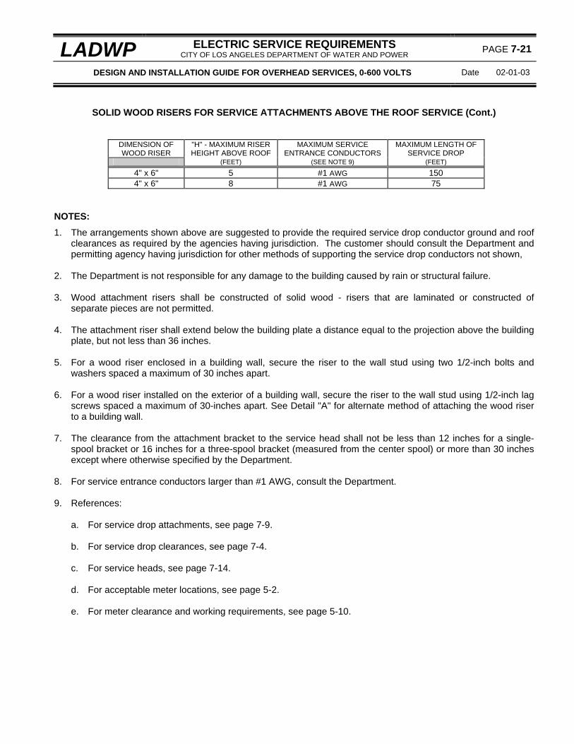
LADWP ELECTRIC SERVICE REQUIREMENTS CITY OF LOS ANGELES DEPARTMENT OF WATER AND POWER
PAGE 7-21
DESIGN AND INSTALLATION GUIDE FOR OVERHEAD SERVICES, 0-600 VOLTS Date 02-01-03
SOLID WOOD RISERS FOR SERVICE ATTACHMENTS ABOVE THE ROOF SERVICE (Cont.)
DIMENSION OF WOOD RISER
"H" - MAXIMUM RISER HEIGHT ABOVE ROOF
MAXIMUM SERVICE ENTRANCE CONDUCTORS
MAXIMUM LENGTH OF SERVICE DROP
(FEET) (SEE NOTE 9) (FEET)
4" x 6" 5 #1 AWG 150 4" x 6" 8 #1 AWG 75
NOTES:
1. The arrangements shown above are suggested to provide the required service drop conductor ground and roof clearances as required by the agencies having jurisdiction. The customer should consult the Department and permitting agency having jurisdiction for other methods of supporting the service drop conductors not shown,
2. The Department is not responsible for any damage to the building caused by rain or structural failure. 3. Wood attachment risers shall be constructed of solid wood - risers that are laminated or constructed of
separate pieces are not permitted. 4. The attachment riser shall extend below the building plate a distance equal to the projection above the building
plate, but not less than 36 inches. 5. For a wood riser enclosed in a building wall, secure the riser to the wall stud using two 1/2-inch bolts and
washers spaced a maximum of 30 inches apart. 6. For a wood riser installed on the exterior of a building wall, secure the riser to the wall stud using 1/2-inch lag
screws spaced a maximum of 30-inches apart. See Detail "A" for alternate method of attaching the wood riser to a building wall.
7. The clearance from the attachment bracket to the service head shall not be less than 12 inches for a single-
spool bracket or 16 inches for a three-spool bracket (measured from the center spool) or more than 30 inches except where otherwise specified by the Department.
8. For service entrance conductors larger than #1 AWG, consult the Department. 9. References:
a. For service drop attachments, see page 7-9. b. For service drop clearances, see page 7-4. c. For service heads, see page 7-14. d. For acceptable meter locations, see page 5-2. e. For meter clearance and working requirements, see page 5-10.

PAGE 7-22 ELECTRIC SERVICE REQUIREMENTS CITY OF LOS ANGELES DEPARTMENT OF WATER AND POWER LADWP
Date: 01-01-09 DESIGN AND INSTALLATION GUIDE FOR OVERHEAD SERVICES, 0-600 VOLTS
CUSTOMER-OWNED TEMPORARY SERVICE POLE - One year Maximum Service 200 AMPERES MAXIMUM, 0-600 VOLTS
FOR POLES EXCEEDING 24 FEET IN LENGTH, see pages 7-24 and 7-26.
NOTES:
1. The pole shall be self-supporting, solid timber and not less than 6 inches x 6 inches in diameter and 20 feet in length. The pole shall be butt-treated and free of knots or other imperfections that could impair the strength of the pole. Laminated poles, or poles constructed of separate pieces, are not permitted.
2. Service drop conductors, the service drop
attachment bracket and the meter shall be furnished and installed by the Department - all other equipment shall be installed by the contractor.
3. Risers shall be 3/4-inch minimum Polyvinyl Chloride (PVC) schedule 40 or metallic conduit and shall be securely attached to the pole.
4. Floodlights, signs, ropes, and other similar
equipment shall not be attached to the pole. 5. The pole shall be located:
a. At least 10 feet from the Department
service pole and, whenever practicable, at least 10 feet laterally from the center of the pole line but not more than 100 feet from the Department’s servicing pole.
b. So that the ground clearance, buildings
and other obstructions shall not reduce the service drop height below the required minimum clearances specified on pages 7-4 to 7-9.
6. A residential meter socket may be used for
125-ampere, single-phase services - a safety-socket meter panel is required for all others.
Note: The short-circuit duty rating of the service equipment must meet or exceed the Department’s fault current value for the installation.
7. Service equipment and receptacles shall be weatherproof, rated for the load to be served and adequately
bonded and grounded.

LADWP ELECTRIC SERVICE REQUIREMENTS CITY OF LOS ANGELES DEPARTMENT OF WATER AND POWER
PAGE 7-23
DESIGN AND INSTALLATION GUIDE FOR OVERHEAD SERVICES, 0-600 VOLTS Date 01-01-05
CUSTOMER-OWNED TEMPORARY SERVICE POLE - One Year Maximum Service (Cont.) 8. The numeric portion of the street address shall be provided on the pole on the side facing the street or drivable
surface. Plastic or metallic numbers of the type used for house addresses are acceptable. 9. Additional references:
a. For safety-socket meter panel details, see pages 2-24 and 2-26. b. Engineering Offices and telephone numbers, see page 1-4.

PAGE 7-24 ELECTRIC SERVICE REQUIREMENTS CITY OF LOS ANGELES DEPARTMENT OF WATER AND POWER LADWP
Date: 01-01-05 DESIGN AND INSTALLATION GUIDE FOR OVERHEAD SERVICES, 0-600 VOLTS
CUSTOMER-OWNED PERMANENT/TEMPORARY WOOD SERVICE POLE 200 AMPERES MAXIMUM, 0-600 VOLTS
NOTES:
1. The pole shall be a self-supporting, fully-treated round pole with a minimum length of 25 feet and a minimum diameter at the top of 5 inches.
2. Service drop conductors, service drop
attachment bracket and the meter shall be furnished and installed by the Department - all other equipment shall be furnished and installed by the contractor.
3. Risers shall be 3/4-inch minimum polyvinyl
Chloride (PVC) schedule 40 or metallic conduit and shall be securely attached to the pole.
4. Floodlights, signs, ropes, and other similar
equipment shall not be attached to the pole. 5. The pole shall be located:
a. At least 10 feet from the Department
service pole and, whenever practicable, at least 10 feet laterally from the center of the pole line but not more than 150 feet from the Department’s servicing pole.
b. So that the ground clearance, buildings
and other obstructions shall not reduce the service drop height below the required minimum clearances specified on pages 7-4 to 7-9.
Note: Consult with the area service planning office to determine the location of the attachment bracket on the pole required to meet the specified clearances.
6. For permanent service applications, a safety-
socket meter panel is required for all commercial services. For temporary service applications, a residential meter socket may be used for a 125-ampere, single-phase service - a safety-socket meter panel is required for all others.
Note: The service equipment short-circuit duty rating must meet or exceed the Department’s fault current value for the installation.

LADWP ELECTRIC SERVICE REQUIREMENTS CITY OF LOS ANGELES DEPARTMENT OF WATER AND POWER
PAGE 7-25
DESIGN AND INSTALLATION GUIDE FOR OVERHEAD SERVICES, 0-600 VOLTS Date 01-01-05
CUSTOMER-OWNED PERMANENT/TEMPORARY WOOD SERVICE POLE (Cont.) 7. The numeric portion of the street address shall be provided on the pole on the side facing the street or drivable
surface. Plastic or metallic numbers of the type used for house addresses are acceptable. 8. Additional references:
a. For safety-socket meter panel details, see pages 2-24 and 2-26. b. Engineering offices and telephone numbers, see page 1-4.

PAGE 7-26 ELECTRIC SERVICE REQUIREMENTS CITY OF LOS ANGELES DEPARTMENT OF WATER AND POWER LADWP
Date: 02-01-03 DESIGN AND INSTALLATION GUIDE FOR OVERHEAD SERVICES, 0-600 VOLTS
CUSTOMER-OWNED PERMANENT/TEMPORARY METAL SERVICE POLE 200 AMPERES MAXIMUM, 0-600 VOLTS
ATTACHMENT DETAIL SEE NOTE 2
NOTES:
1. The service pole shall be constructed of a continuous, unbroken length of pipe provided with a pipe cap. The pipe shall be hot-dipped galvanized and threaded for attachment of the pipe cap. Acceptable grades for metal pipe are ASTM-A-53 (Type E or S), ASTM-A-500 and ASTM-A-501. Minimum pipe sizes shall conform to the following table:
(H) MINIMUM POLE HEIGHT
ABOVE GROUND (FEET)* (D) MINIMUM POLE DEPTH
BELOW GROUND (FEET) SCHEDULE 40
(STANDARD) SCHEDULE 80
(EXTRA STRONG)
15 4 4" (GRADE B) 4" (GRADE A) 20 4-1/2 5" (GRADE A) 4" (GRADE B) 25 5 5" (GRADE B) 5" (GRADE A)
∗ Required pole height is based on the location of the point of attachment. See note 6b.

LADWP ELECTRIC SERVICE REQUIREMENTS CITY OF LOS ANGELES DEPARTMENT OF WATER AND POWER
PAGE 7-27
DESIGN AND INSTALLATION GUIDE FOR OVERHEAD SERVICES, 0-600 VOLTS Date 02-01-03
CUSTOMER-OWNED PERMANENT/TEMPORARY METAL SERVICE POLE (Cont.) 2. Attachments to metal poles shall be made with devices that will not affect the strength or integrity of the pole
(see attachment detail). Drilling or welding are not acceptable. 3. The Department will furnish the attachment bracket and furnish and install the service drop conductors and
meter. The customer shall install the attachment bracket and shall furnish and install the pole and all other equipment.
4. Riser conduits shall be 3/4-inch minimum polyvinyl Chloride (PVC) schedule 40 or metallic conduit. Metallic
riser conduits are not required to be covered as long as the metal pole is effectively grounded and the metallic conduits are bonded to the pole. If a protective covering is required, see page 121 for conduit covering details.
5. Floodlights, signs, ropes, and other similar equipment shall not be attached to the pole. 6. The pole shall be located:
a. At least 10 feet from the Department service pole and, whenever practicable, at least 10 feet laterally from
the center of the pole line but not more than 150 feet from the Department’s servicing pole. b. So that the ground clearance, buildings and other obstructions shall not reduce the service drop height
below the required minimum clearances specified on pages 7-4 to 7-9. Note: Consult with the area service planning office to determine the location of the attachment bracket on
the pole required to meet the specified clearances.
7. For permanent service applications, a safety-socket meter panel is required for all commercial services. For temporary service applications, a residential meter socket may be used for a 125-ampere, single-phase service - a safety-socket meter panel is required for all others.
Note: The service equipment short-circuit duty rating must meet or exceed the Department’s fault current value for the installation.
8. The numeric portion of the street address shall be provided on the pole on the side facing the street or drivable
surface. Plastic or metallic numbers of the type used for house addresses are acceptable. 9. Additional references:
a. For safety-socket meter panel details, see pages 2-24 and 2-26. b. Engineering offices and telephone numbers, see page 1-4.

PAGE 7-28 ELECTRIC SERVICE REQUIREMENTS CITY OF LOS ANGELES DEPARTMENT OF WATER AND POWER LADWP
Date: 02-01-03 DESIGN AND INSTALLATION GUIDE FOR OVERHEAD SERVICES, 0-600 VOLTS
THIS PAGE LEFT INTENTIONALLY BLANK

LADWP ELECTRIC SERVICE REQUIREMENTS CITY OF LOS ANGELES DEPARTMENT OF WATER AND POWER
PAGE 8-1
DESIGN GUIDE FOR CUSTOMER-OWNED PARALLEL GENERATING SYSTEMS Date 01-01-10
CONTENTS
PAGE
A. Introduction . . . . . . . . . . . . . . . . . . . . . . . . . . . . . . . . . . . . . . . . . . . . . . . . . . . . . . . . . . . . . . . . . . 8-1
B. Data Required for Design . . . . . . . . . . . . . . . . . . . . . . . . . . . . . . . . . . . . . . . . . . . . . . . . . . . . . . . 8-2
C. Electric Rates . . . . . . . . . . . . . . . . . . . . . . . . . . . . . . . . . . . . . . . . . . . . . . . . . . . . . . . . . . . . . . . . 8-3
D. Self-Generation Interconnection Agreements . . . . . . . . . . . . . . . . . . . . . . . . . . . . . . . . . . . . . . . . 8-3
E. Interconnection Costs . . . . . . . . . . . . . . . . . . . . . . . . . . . . . . . . . . . . . . . . . . . . . . . . . . . . . . . . . . 8-3
F. Transformer Requirements . . . . . . . . . . . . . . . . . . . . . . . . . . . . . . . . . . . . . . . . . . . . . . . . . . . . . . 8-3
G. Operating Requirements . . . . . . . . . . . . . . . . . . . . . . . . . . . . . . . . . . . . . . . . . . . . . . . . . . . . . . . . 8-3
H. Metering . . . . . . . . . . . . . . . . . . . . . . . . . . . . . . . . . . . . . . . . . . . . . . . . . . . . . . . . . . . . . . . . . . . . 8-4
I. Inspections . . . . . . . . . . . . . . . . . . . . . . . . . . . . . . . . . . . . . . . . . . . . . . . . . . . . . . . . . . . . . . . . . . 8-4
J. Liability . . . . . . . . . . . . . . . . . . . . . . . . . . . . . . . . . . . . . . . . . . . . . . . . . . . . . . . . . . . . . . . . . . . . . 8-4
K. Disconnection of the Customer’s Energy Sources . . . . . . . . . . . . . . . . . . . . . . . . . . . . . . . . . . . . . 8-4
1. General . . . . . . . . . . . . . . . . . . . . . . . . . . . . . . . . . . . . . . . . . . . . . . . . . . . . . . . . . . . . . . . . . 8-42. Notification . . . . . . . . . . . . . . . . . . . . . . . . . . . . . . . . . . . . . . . . . . . . . . . . . . . . . . . . . . . . . . . 8-5
L. Generation Disconnecting Means . . . . . . . . . . . . . . . . . . . . . . . . . . . . . . . . . . . . . . . . . . . . . . . . . . . 8-5
1. General . . . . . . . . . . . . . . . . . . . . . . . . . . . . . . . . . . . . . . . . . . . . . . . . . . . . . . . . . . . . . . . . . 8-52. Access . . . . . . . . . . . . . . . . . . . . . . . . . . . . . . . . . . . . . . . . . . . . . . . . . . . . . . . . . . . . . . . . . . 8-5
M. Informational Signs . . . . . . . . . . . . . . . . . . . . . . . . . . . . . . . . . . . . . . . . . . . . . . . . . . . . . . . . . . . . 8-6
N. Protective Schemes . . . . . . . . . . . . . . . . . . . . . . . . . . . . . . . . . . . . . . . . . . . . . . . . . . . . . . . . . . . 8-6
O. Telemetry . . . . . . . . . . . . . . . . . . . . . . . . . . . . . . . . . . . . . . . . . . . . . . . . . . . . . . . . . . . . . . . . . . . 8-7
P. Maintenance . . . . . . . . . . . . . . . . . . . . . . . . . . . . . . . . . . . . . . . . . . . . . . . . . . . . . . . . . . . . . . . . . 8-7
Q. Records . . . . . . . . . . . . . . . . . . . . . . . . . . . . . . . . . . . . . . . . . . . . . . . . . . . . . . . . . . . . . . . . . . . . 8-7
R. Specifications . . . . . . . . . . . . . . . . . . . . . . . . . . . . . . . . . . . . . . . . . . . . . . . . . . . . . . . . . . . . . . . . 8-8
S. Testing and Evaluation . . . . . . . . . . . . . . . . . . . . . . . . . . . . . . . . . . . . . . . . . . . . . . . . . . . . . . . . . 8-8
T. Generators and Generating Systems . . . . . . . . . . . . . . . . . . . . . . . . . . . . . . . . . . . . . . . . . . . . . . . . . 8-9
U. Inverters . . . . . . . . . . . . . . . . . . . . . . . . . . . . . . . . . . . . . . . . . . . . . . . . . . . . . . . . . . . . . . . . . . . . 8-10
Illustrations:
Typical Interconnected Arrangement with Department-Owned Transformers . . . . . . . . . . . . . . . . . 8-12
Typical Interconnected Arrangement with Customer-Owned Transformers . . . . . . . . . . . . . . . . . . . 8-14

PAGE 8-2 ELECTRIC SERVICE REQUIREMENTS CITY OF LOS ANGELES DEPARTMENT OF WATER AND POWER LADWP
Date: 01-01-07 DESIGN GUIDE FOR CUSTOMER-OWNED PARALLEL GENERATING SYSTEMS
A. INTRODUCTION
1. This section is intended to assist Department customers in the design and evaluation of utility
interconnections for customer-owned parallel-generation systems. 2. Interconnection agreement packages are available for proposed customer-owned parallel-generation
facilities and may be obtained by contacting: Los Angeles Department of Water and Power Distribution Engineering Self-Generation Project Manager 111 North Hope Street Room 819 Los Angeles, CA 90012 Tel: (213) 367-3413 FAX: (213) 367-2919
B. DATA REQUIRED FOR DESIGN
1. When considering the installation of a parallel-generation facility, customers should contact the Department
as soon as possible so that: a. The Department’s service planners can work with the customer to establish an acceptable
interconnection scheme for the customer’s facility. b. Customers may avoid unnecessary expenses and delays in service caused by assuming
interconnection schemes and equipment requirements.
2. At the time of initial contact, or as soon as possible, customers should provide the Department with the following information so that the Department may assist the customer in finalizing the customer’s plans: a. Electrical plans including load schedules and single-line diagrams. b. Plot and site development plans showing generator, disconnect, metering equipment locations and
Department access to generator, disconnect and meter equipment locations. c. Energy source information:
(1) Maximum kilowatt rating (2) Nominal voltage output (3) Voltage regulation (4) Maximum fault current contribution
d. Protective system information: (1) Protective system plan (2) Manufacturer’s data sheets and maintenance requirements for protective equipment (3) Any additional information required by the Department

LADWP ELECTRIC SERVICE REQUIREMENTS CITY OF LOS ANGELES DEPARTMENT OF WATER AND POWER
PAGE 8-3
DESIGN GUIDE FOR CUSTOMER-OWNED PARALLEL GENERATING SYSTEMS Date 02-01-03
B. DATA REQUIRED FOR DESIGN (Cont.)
3. Upon receiving the requested information and engineering fees, the Department will provide customer requirements drawings and Department construction drawings as needed. Customer requirement drawings provide the customer with the information necessary to construct the interconnection facilities for the transformers, protective devices, meters and other necessary equipment that will be installed by the Department.
C. ELECTRIC RATES
Rates for the sale or exchange of electrical energy between the Department and the customer shall be in accordance with the established rates as specified in the latest publication of the Department’s Rate Ordinance as amended.
D. SELF-GENERATION INTERCONNECTION AGREEMENTS 1. Customers are required to complete a Self-Generation Interconnection Agreement (Agreement) with the
Department before the generating facility may be interconnected to the Department’s electric system. 2. The Department normally uses a standard offer contract for Agreements. However, if the standard offer is
not suitable for the needs of the generating facility, the customer may request the Department to consider a separate nonstandard interconnection agreement.
E. INTERCONNECTION COSTS
Customers are required to reimburse the Department for all expenses associated with completing the interconnection of the customer’s parallel-generation facilities including, but not limited to, extensions or modifications to the Department’s electric system and related facilities and construction costs.
F. TRANSFORMER REQUIREMENTS 1. Energy sources rated less than 500kVA may be connected on the secondary side of Department-owned
transformers supplied from the 4800-volt electric system. 2. Energy sources rated 500-750 kVA may be required to be connected on the secondary side of dedicated
Department-owned transformers supplied from the 34,500-volt electric system. 3. Energy sources rated over 750 kVA will be required to be connected on the secondary side of dedicated
Department-owned transformers supplied from the 34,500-volt electric system. Transformers shall be sized to supply the complete installation and will serve no other customer. Secondary distribution may be provided at the most convenient serving voltage for the customer.
4. The Department may require that the Department-owned transformers used to supply the customer’s
electric system be sized (i.e., kVA rating) equal to, or greater than, the customer’s total generator capacity. 5. See TRANSFORMER INSTALLATIONS ON THE CUSTOMER’S PREMISES on page 1-33 for additional
information.
G. OPERATING REQUIREMENTS
1. Customers are required to operate the generating facilities, whether permanent or temporary, in accordance with the Agreement, The Department’s Electric Service Requirements, Rules, Rate Schedules and all other applicable codes and ordinances.

PAGE 8-4 ELECTRIC SERVICE REQUIREMENTS CITY OF LOS ANGELES DEPARTMENT OF WATER AND POWER LADWP
Date: 01-01-09 DESIGN GUIDE FOR CUSTOMER-OWNED PARALLEL GENERATING SYSTEMS
G. OPERATING REQUIREMENTS (Cont.)
2. Customers shall not:
a. Energize an un-energized electric line or transformer. b. Reconnect the energy source after a protective device trip unless the customer’s electric system is
energized by the Department’s electric system by the Department, or unless the customer’s electric system is isolated from the Department’s electric system by the Department
3. Synchronous generators are capable of maintaining a distribution system energized even after the line
protective device has opened and separated (relayed) the line from the Department’s electric system. Since the Department uses automatic reclosing schemes to energize relayed lines after a short time delay, customer-owned equipment or Department-owned equipment may be damaged if power is restored to a line that is already energized by the customer’s generator(s).
4. These operating and protective requirements have been established to protect the health and well being
of the public and utility workers from malfunctions in Department or customer equipment.
H. METERING 1. Customers shall provide Department approved metering arrangements for the installation of Department-
owned meters to measure the energy into, or out of, the installation at the interconnection point and at the energy source(s) output.
2. All metering equipment drawings must be submitted to, and approved by, the Department service planner
before the customer installs any equipment.
I. INSPECTIONS The Department requires that all conditions specified by these requirements be met and verified by the Department. In addition, an approval from the permitting agency for portions of the wiring and electrical equipment under their jurisdiction is required before the Department will establish the interconnection.
J. LIABILITY 1. Customers are responsible for damage caused to Department-owned equipment or other customers
served from the Department’s electric lines as a result of mis-operation or malfunction of the customer’s energy source system.
2. The Department does not assume any responsibility for the protection of the customer’s generator(s) or
any other portion of the customer’s electrical system. The customer is fully responsible for protecting the customer’s system so that faults or other disturbances on the Department’s system do not cause damage to the customer’s equipment.
K. DISCONNECTION OF CUSTOMER’S ENERGY SOURCES
1. GENERAL
The Department reserves the right to disconnect the customer’s energy source(s) from the Department’s electric system: a. When the customer’s energy source is adversely affecting the Department’s electric system or other
customer’s supplied from the Department’s electric system.

LADWP ELECTRIC SERVICE REQUIREMENTS CITY OF LOS ANGELES DEPARTMENT OF WATER AND POWER
PAGE 8-5
DESIGN GUIDE FOR CUSTOMER-OWNED PARALLEL GENERATING SYSTEMS Date 01-01-10
K. DISCONNECTION OF CUSTOMER’S ENERGY SOURCES (Cont.)
b. When the customer-installed protective system has been defeated or not properly maintained (lack of
proper records is considered to be non-maintenance). c. If the customer denies access to the Department to the generating facility or to required maintenance
and operating records. d. Under emergency conditions as determined by the Department.
2. NOTIFICATION a. Under non-emergency conditions, generally a notice of disconnection will be provided in writing as
follows: (1) For energy sources rated less than 500 kVA, the Department will endeavor to provide notification
72 hours in advance of the scheduled disconnection (2) For energy sources rated 500 kVA or greater, the Department will provide notification 72 hours in
advance of the scheduled disconnection
b. Under emergency conditions, the Department reserves the right to disconnect the customer’s energy source(s) without notification.
c. If the customer-installed protective system becomes inoperative, the customer shall disconnect the
energy source(s) from the Department’s electric system and immediately notify the Department. When the protective system problems have been corrected, the customer shall request the Department for permission to reconnect the customer generation system.
L. GENERATION DISCONNECTING MEANS
1. GENERAL
a. Customers shall furnish, install and maintain circuit disconnect switches as required by the Department
to isolate the customer’s generator or generating system from the Department’s electric system. In general, a main service generator disconnect switch and a generator circuit disconnect switch will be required for synchronous generating systems while only a generator circuit disconnect switch will be required for induction or solar generating systems. See pages 8-12 and 8-14 for additional requirements.
b. The Department circuit disconnect switch shall be a safety switch with a readily verifiable visual air gap
to assure positive circuit disconnect and shall be lockable in the open position. Locking provisions shall have a 3/8-inch minimum hole for use with a Department standard padlock having a 1-inch locking clearance.
Note: Safety switches shall have a viewing window to allow verification of the open switch condition without exposing the Department’s personnel to energized bus and shall be independent of the customer’s required circuit protection devices (i.e., circuit breakers or fuses). Removing customer-owned fuses shall not be permitted as a means of providing the required air gap.
2. ACCESS
Switches used to disconnect the energy source shall be accessible under all conditions and at all times to Department personnel. This may require disconnect switches to be located in a publicly accessible area or be provided with an interlock system to gain access to an installation in a security controlled area.

PAGE 8-6 ELECTRIC SERVICE REQUIREMENTS CITY OF LOS ANGELES DEPARTMENT OF WATER AND POWER LADWP
Date: 01-01-09 DESIGN GUIDE FOR CUSTOMER-OWNED PARALLEL GENERATING SYSTEMS
M. SIGNS AND LABELS
1. The customer shall provide and install the following signs as directed by the Department: a. A sign at the main service (meter) panel location identifying each generator disconnect location. b. A sign at each Department specified generator disconnect identifying the main service location. c. A sign on each personnel entrance door for Customer Stations. d. Any other signs deemed necessary by the Department to provide generator disconnect location
information.
2. The customer shall provide a sign to be installed by the Department for each Department-owned padmount transformer connected to the customer’s parallel generation system.
3. The customer shall provide and install the following diagrams when required by the Department: a. A single-line diagram located at the main service panel location. The diagram shall be approved by the
Department and installed by the customer as directed by the Department. b. A plot plan located at the main service panel showing the location of the generator disconnect(s). The
plot plan shall be approved by the Department and installed by the customer as directed by the Department.
N. PROTECTIVE SCHEMES
1. Customer generating facilities shall be provided with protective schemes in order to insure the security of
the Department’s electric system, security of other customers supplied from the Department’s electric system and the safety of Department operating personnel.
2. In general, The Department will provide and install, at the customer’s cost, required protective equipment.
However, where mutually agreeable between the Department and the customer, the customer may provide and install, at the customer’ cost, protective equipment as specified by the Department for: a. Synchronous generators rated less than 300 KVA (240 KW) and induction generators rated less than
400 KVA (480 kW) when supplied from the Department’s 4800-volt electric system. b. Synchronous generators rated less than 400 KVA (320 kW) and induction generators rated less than
600 KVA (480 KW) when supplied from the Department’s 34, 500-volt electric system. 3. The Department will install ground fault protection (GFP) equipment, at the customer’s cost, for customer
generating facilities rated one megawatt (MW) and above and interconnected with the Department’s 34,500-volt electric system.
Note: The Department may require GFP for customer generation facilities rated less than one MW and interconnected with the Department’s 34,500-volt electric system when the facilities are located in remote areas or whenever such protection, in the Department’s judgment, is necessary.
4. The electrical rating (kW) of the customer’s generating facility will determine, in part, the configuration in
operating characteristics and protection requirements for a customer’s interconnection installation. Typical protection equipment requirements include, but are not limited to: a. Under-voltage (Device 27) protection

LADWP ELECTRIC SERVICE REQUIREMENTS CITY OF LOS ANGELES DEPARTMENT OF WATER AND POWER
PAGE 8-7
DESIGN GUIDE FOR CUSTOMER-OWNED PARALLEL GENERATING SYSTEMS Date 01-01-04
N. PROTECTIVE SCHEMES (Cont.)
b. Over-voltage (Device 59) protection c. Under-frequency (Device 81U) protection d. Over-frequency (Device 81O) protection e. Tripping batteries, circuit breakers and battery chargers
Note: See SPECIFICATIONS on page 8-8 for additional information. 5. Customer’s energy source circuit breakers must positively disconnect under all conditions. In most
instances this will require the installation of a charger assisted, uninterruptible D.C. power source. 6. The Department reserves the right to review and approve any interconnection scheme involving customer
initiation of the customer interconnecting breaker controls. 7. Protective equipment shall be readily accessible to the department for periodic inspection.
O. TELEMETRY 1. Customers shall provide an operating telephone service at each energy source installation when required
by the Department. 2. For installation rated one MW and above, the Department requires that customer install telemetering
equipment at the generating facility to provide continuous output information at the Department’s Energy Control Center. This information shall include, but not be limited to: a. Energy source watts and watt-hours. b. An indication of each energy source synchronizing disconnect information (i.e., open or closed).
P. MAINTENANCE 1. Where the Department installs the protective equipment, the Department is responsible for maintaining
such equipment. Where the customer installs the required protective equipment, the customer shall provide monthly maintenance of the tripping battery and the battery charger.
2. For customer generation installations rated 500 kVA or more, maintenance of the customer’s energy
source must be scheduled in advance to be compatible with the Department’s electric system load requirements.
Q. RECORDS
1. Customers shall provide accurate records of the customer’s generating facility. Such records shall include
but not be limited to:
a. Tripping batteries and battery chargers, where protective equipment is installed by the customer: (1) Date and time of maintenance (2) Description of maintenance performed

PAGE 8-8 ELECTRIC SERVICE REQUIREMENTS CITY OF LOS ANGELES DEPARTMENT OF WATER AND POWER LADWP
Date: 01-01-10 DESIGN GUIDE FOR CUSTOMER-OWNED PARALLEL GENERATING SYSTEMS
Q. RECORDS (Cont.)
b. Each energy source:
(1) On-line and off-line times (2) Generation output (kW) (3) Maintenance outages (4) Trip operations (5) Any unusual events
2. The Department reserves the right to periodically review the customer’s maintenance records for system analysis and to evaluate system disturbances.
R. SPECIFICATIONS
1. Customer generating facilities shall be constructed to meet the following specifications:
a. System frequency shall be 60 cycles per second (Hz). b. Signal distortion shall be limited to 5-percent of the RMS value of the Department’s serving voltage and
25-percent of the waveform. c. Power factor of the customer’s electric system shall be limited as follows:
(1) For generating systems rated less than one MW, the average monthly on-peak power factor shall
not be less than 85-percent lagging. (2) For generating systems rated one MW or greater, the power factor shall not be less than 99.5-
percent lagging or more than 99.5-percent leading.
Note: The Department will measure these specifications at the metering facility.
2. Protective equipment relays used to open and close generator circuit breakers shall operate with the following specifications: a. Under-voltage (Device 27), 92 volts or higher with a maximum time delay of 2.0 seconds b. Over-voltage (device 59), 138 volts or less with a maximum time delay of 2.0 seconds c. Under-frequency (Device 81U), 57 Hz or higher with a maximum time delay of 2.5 seconds d. Over-frequency (Device 81O), 61 HZ or less with a maximum time delay of 2.5 seconds
S. TESTING AND EVALUATION 1. Customers shall test the generating facility before interconnecting with the Department’s electric system
and provide written certification to the Department that the generating facility meets the Department’s specifications.

LADWP ELECTRIC SERVICE REQUIREMENTS CITY OF LOS ANGELES DEPARTMENT OF WATER AND POWER
PAGE 8-9
DESIGN GUIDE FOR CUSTOMER-OWNED PARALLEL GENERATING SYSTEMS Date 01-01-10
S. TESTING AND EVALUATION (Cont.)
2. The Department reserves the right to test the customer’s equipment before approving the connection to the
Department’s electric system and the right to monitor onsite operations of the equipment. 3. If the generating facility does not meet the Department’s specifications, the Department may require the
customer to disconnect the facility and make corrections or reimburse the Department for corrections as specified in the Agreement.
4. After the Department determines that the operation of an energy source will not be hazardous or impair the
reliability of the Department’s electric system, the Department will provide written permission to complete the interconnection
5. Where the customer installs protective equipment, the customer shall have the equipment tested at two-
year intervals by a Department approved testing agency at the customer’s cost. It is the customer’s responsibility to arrange for contracts and payments to the approved testing agency and to complete testing within the two-year interval.
T. GENERATORS AND GENERATING SYSTEMS
1. Generating systems operated by customers shall be connected on the customer’s electric system on the
load side of the customer’s service disconnecting means at a Department approved location.
Exception: Solar (photovoltaic) and fuel cell generating systems may be connected on either the line side or load side of the customer’s service disconnecting means as allowed by the permitting agency but are subject to the following restrictions:
a. Generation circuit connections may not be made in, or accessed through, any sealed utility compartment.
b. Generation circuit conduits and conductors shall not be routed through any sealed utility
compartment.
Note: sealed utility compartments include terminating pull boxes and pull sections, metering compartments, and test-bypass compartments.
Caution: Existing service equipment may not have a suitable solar or fuel cell connection point on the
line side of the customer’s service over-current device and may require third party certification of any proposed connection location. Consult the LADBS or other applicable permitting agency regarding third party cerification requirements.
2. Single-phase energy sources are limited to 20 kVA for each unit. Installations with multiple single-phase
units shall use a three-phase interconnection system and balance the sources between the phases. 3. For synchronous generators, automatic synchronization is preferred. However, manual synchronization
with relay supervision is acceptable. 4. Synchronous generators designed to be started as induction motors may not require synchronizing relays,
but will not be permitted to start up if it results in detrimental effects to the Department’s electric system. 5. Voltage regulation equipment must be provided on the customer’s generator to maintain generation voltage
to within normal Department limits. 6. Induction generator installations may require capacitors to correct the power factor. Protection schemes
must be coordinated to insure that the capacitors will always be disconnected before the induction generator is disconnected.

PAGE 8-10 ELECTRIC SERVICE REQUIREMENTS CITY OF LOS ANGELES DEPARTMENT OF WATER AND POWER LADWP
Date: 01-01-10 DESIGN GUIDE FOR CUSTOMER-OWNED PARALLEL GENERATING SYSTEMS
T. GENERATORS AND GENERATING SYSTEMS (Cont.)
7. Generator installations rated 750 kVA or less may be required by the Department to meet conditions and specifications normally required for installations rated over 750 kVA. Safeguards that will be required and the degree of sophistication will depend on the type of equipment and the interconnection scheme.
U. INVERTERS
1. Inverters shall be utility interactive (i.e., inverter requires a utility voltage source to operate) . Stand-alone
inverters designed for customer electric systems that are operated independent the utility grid and dual-operation inverters that may be operated in either stand-alone or utility interactive modes are not permitted.
2. Inverters may be used to interface the customer’s energy source with the Department’s electric system and
shall be designed to operate within the Department’s acceptable service supply voltage ranges. See Acceptable Voltage Ranges, page 1-26, for additional information.
3. Inverters require connection through an isolation transformer to prevent the introduction of a D.C.
component onto the Department’s electric system caused by an inverter malfunction. The transformer may provide a one-to-one ratio or may match the inverter output voltage to the interconnection voltage.
4. Inverters are required to be line commutated and line feeding. 5. Suitable safeguards are required to prevent connection when the inverter is not synchronous with the
Department’s electric system. 6. Inverter designs shall provide a “ramp in” feature during the interconnection operation (i.e., power will
gradually ramp up from zero on the initial start up) to prevent voltage fluctuations. 7. Inverters are to be designed to operate as current sources rather than voltage sources due to the inherent
stiffness of the Department’s electric system.

LADWP ELECTRIC SERVICE REQUIREMENTS CITY OF LOS ANGELES DEPARTMENT OF WATER AND POWER
PAGE 8-11
DESIGN GUIDE FOR CUSTOMER-OWNED PARALLEL GENERATING SYSTEMS Date 01-01-10
THIS PAGE LEFT INTENTIONALLY BLANK

PAGE 8-12 ELECTRIC SERVICE REQUIREMENTS CITY OF LOS ANGELES DEPARTMENT OF WATER AND POWER LADWP
Date: 01-01-10 DESIGN GUIDE FOR CUSTOMER-OWNED PARALLEL GENERATING SYSTEMS
TYPICAL INTERCONNECTION ARRANGEMENTS WITH DEPARTMENT-OWNED TRANSFORMERS
FIG. 1 TYPICAL INTERCONNECTION ARRANGEMENT FOR CUSTOMER-OWNED GENERATING SYSTEMS
FIG. 2 ALTERNATE INTERCONNECTION ARRANGEMENT FOR CUSTOMER-OWNED SOLAR/FUEL CELL GENERATING SYSTEMS

LADWP ELECTRIC SERVICE REQUIREMENTS CITY OF LOS ANGELES DEPARTMENT OF WATER AND POWER
PAGE 8-13
DESIGN GUIDE FOR CUSTOMER-OWNED PARALLEL GENERATING SYSTEMS Date 01-01-10
TYPICAL INTERCONNECTION ARRANGEMENTS WITH
DEPARTMENT-OWNED TRANSFORMERS NOTES: 1. The customer shall furnish, install and maintain equipment disconnect devices as required by the Department.
The main service generator disconnect device is not required for generating facilities using only induction energy sources.
2. The customer’s generating system circuit shall be connected on the load side of the customer’s service
disconnecting means (Main CB) as shown in figure 1.
Exception: Solar and fuel cell generating systems may be connected on the line side of the customer’s disconnecting means as shown in figure 2. For additional information, see page 8-9, “Generators and Generating Systems”.
3. The customer shall provide facilities for installation of a Department performance (unit) meter. A safety-socket
meter panel is required for feeder circuit breaker (CB) ratings up to 250 amperes. When the feeder CB rating exceeds 250 amperes, a current-transformer box or instrument-rated switchboard is required.
Exception: Residential solar systems rated under 10kW require a customer-owned meter socket and meter as specified under the Department’s Solar Guidelines. The guidelines are available on the Department’s website at www.ladwp.com.
4. References:
a. For additional LADWP generating system disconnect device requirements, see page 8-5. b. For metering requirements, see:
(1) Sections 2 and 3 for facilities to be metered at 0-600 volts. (2) Section 4 for facilities to be metered at 601-4800 volts.
c. For transformer installations, see page 8-3.

PAGE 8-14 ELECTRIC SERVICE REQUIREMENTS CITY OF LOS ANGELES DEPARTMENT OF WATER AND POWER LADWP
Date: 01-01-10 DESIGN GUIDE FOR CUSTOMER-OWNED PARALLEL GENERATING SYSTEMS
TYPICAL INTERCONNECTION ARRANGEMENT WITH CUSTOMER-OWNED TRANSFORMERS
NOTES: 1. The customer shall furnish, install and maintain equipment disconnect devices as required by the Department.
The Department may install additional disconnect devices, at the customer’s expense, if the generating facility uses synchronous generators.
2. The customer shall provide facilities for installation of a Department performance (unit) meter. A safety-socket
meter panel is required for feeder CB ratings up to 200 amperes. When the feeder CB rating exceeds 200 amperes, a current-transformer box or instrument-rated switchboard is required.
3. References:
a. For generator disconnect requirements, see page 8-5.

LADWP ELECTRIC SERVICE REQUIREMENTS CITY OF LOS ANGELES DEPARTMENT OF WATER AND POWER
PAGE 9-1
INDEX AND GLOSSARY Date 01-01-05
CONTENTS PAGE
Index . . . . . . . . . . . . . . . . . . . . . . . . . . . . . . . . . . . . . . . . . . . . . . . . . . . . . . . . . . . . . . . . . . . . . . . . . . . . 9-2 EUSERC/ESR Cross Reference and Acceptability Index . . . . . . . . . . . . . . . . . . . . . . . . . . . . . . . . . . . . . 9-9 Glossary . . . . . . . . . . . . . . . . . . . . . . . . . . . . . . . . . . . . . . . . . . . . . . . . . . . . . . . . . . . . . . . . . . . . . . . . . 9-11

PAGE 9-2 ELECTRIC SERVICE REQUIREMENTS CITY OF LOS ANGELES DEPARTMENT OF WATER AND POWER LADWP
Date: 01-01-09 INDEX AND GLOSSARY
INDEX Section 1, General Information . . . . . . . . . . . . . . . . . . . . . . . . . . . . . . . . . . . . . . . . . . . . . . . . . . . . . . . . 1-1Section 2, Service and Metering Equipment . . . . . . . . . . . . . . . . . . . . . . . . . . . . . . . . . . . . . . . . . . . . . . . 2-1Section 3, Low-Voltage Switchboards, 0-600 Volts . . . . . . . . . . . . . . . . . . . . . . . . . . . . . . . . . . . . . . . . . 3-1Section 4, Medium-Voltage Switchgear, 2400-4800 Volts . . . . . . . . . . . . . . . . . . . . . . . . . . . . . . . . . . . . . 4-1Section 5, Design and Installation Guide for Service and Metering Equipment . . . . . . . . . . . . . . . . . . . . 5-1Section 6, Design and Installation Guide for Conduit Systems on Private Property . . . . . . . . . . . . . . . . . 6-1Section 7, Design and Installation Guide for Overhead Services, 0-600 Volts . . . . . . . . . . . . . . . . . . . . . 7-1Section 8, Design Guide for Customer-Owned Parallel Generating Systems . . . . . . . . . . . . . . . . . . . . . . 8-1Section 9, Index and Glossary . . . . . . . . . . . . . . . . . . . . . . . . . . . . . . . . . . . . . . . . . . . . . . . . . . . . . . . . . 9-1
A
Angle Iron Racks, Overhead Service . . . . . . . . . . . . . . . . . . . . . . . . . . . . . . . . . . . . . . . . . . . . . . . . 7-16, 717Application for Service . . . . . . . . . . . . . . . . . . . . . . . . . . . . . . . . . . . . . . . . . . . . . . . . . . . . . . . . . . 1-8, 1-29Applications, Use of Service and Metering Equipment . . . . . . . . . . . . . . . . . . . . . . . . . . . . . . . . . . 2-10, 3-11Attachment brackets for Service Drop Conductors (See Overhead Services, Design and Installation Guide)
B
Barrier Posts . . . . . . . . . . . . . . . . . . . . . . . . . . . . . . . . . . . . . . . . . . . . . . . . . . . . . . . . . . . . . . . . . . . . 5-13, 5-15Barriers, Service and Metering Equipment . . . . . . . . . . . . . . . . . . . . . . . . . . . . . . . . . . . . . . . . . . . . . 3-4, 4-2Bonding . . . . . . . . . . . . . . . . . . . . . . . . . . . . . . . . . . . . . . . . . . . . . . . . . . . . . . . . . . . . . . . . . . 2-9, 3-10, 4-3Busway Services . . . . . . . . . . . . . . . . . . . . . . . . . . . . . . . . . . . . . . . . . . . . . . . . . . . . . . . . . . 1-36, 3-48, 7-15 C
Changes in Connected Load . . . . . . . . . . . . . . . . . . . . . . . . . . . . . . . . . . . . . . . . . . . . . . . . . . . . . . . . . . 1-21Character of Service . . . . . . . . . . . . . . . . . . . . . . . . . . . . . . . . . . . . . . . . . . . . . . . . . . . . . . . . . . . . . . . . 1-25Classes of Service . . . . . . . . . . . . . . . . . . . . . . . . . . . . . . . . . . . . . . . . . . . . . . . . . . . . . . . . . . . . . . . . . . 1-27Clearances:
Service and Metering Equipment . . . . . . . . . . . . . . . . . . . . . . . . . . . 5-6, 5-1, 5-12, 5-13, 5-14, 5-16, 5-18Service Drop Conductors . . . . . . . . . . . . . . . . . . . . . . . . . . . . . . . . . . . . . . . . . . . . . . . . . . . . . . . . . . 7-4
Conduits:
Bends . . . . . . . . . . . . . . . . . . . . . . . . . . . . . . . . . . . . . . . . . . . . . . . . . . . . . . . . . . . . . . . . . . . . . . . . . 6-4Concrete Encasement . . . . . . . . . . . . . . . . . . . . . . . . . . . . . . . . . . . . . . . . . . . . . . . . . . . . . . . . . . . . 6-5Depth . . . . . . . . . . . . . . . . . . . . . . . . . . . . . . . . . . . . . . . . . . . . . . . . . . . . . . . . . . . . . . . . . . . . . . . . 6-4Types of (metallic and nonmetallic) . . . . . . . . . . . . . . . . . . . . . . . . . . . . . . . . . . . . . . . . . . . . . . . . 6-3, 6-4Pull Tape . . . . . . . . . . . . . . . . . . . . . . . . . . . . . . . . . . . . . . . . . . . . . . . . . . . . . . . . . . . . . . . . . . . . . . 6-6Risers, Conduit . . . . . . . . . . . . . . . . . . . . . . . . . . . . . . . . . . . . . . . . . . . . . . . . . 6-6, 7-14, 7-16, 7-18, 7-20Sizes . . . . . . . . . . . . . . . . . . . . . . . . . . . . . . . . . . . . . . . . . . . . . . . . . . . . . . . . . . . . . . . . . . . . . . . . . 6-3Spacing Between Ducts . . . . . . . . . . . . . . . . . . . . . . . . . . . . . . . . . . . . . . . . . . . . . . . . . . . . . . . . . . . 6-5
Cooking Loads . . . . . . . . . . . . . . . . . . . . . . . . . . . . . . . . . . . . . . . . . . . . . . . . . . . . . . . . . . . . . . . . . . . . . 1-22Current-Transformer Compartments . . . . . . . . . . . . . . . . . . . . . . . . . . . . . . . 3-20, 3-22, 3-24, 3-26, 3-28, 4-6Current-Transformer Boxes, Wall-Mounted . . . . . . . . . . . . . . . . . . . . . . . . . . . . . . . . . . . . . . . . . 2-34, 2-36Current-Transformer Mounting Bases . . . . . . . . . . . . . . . . . . . . . . . . . . . . . . 2-38, 2-39, 2-40, 2-41, 3-30, 3-31Current-Transformer Mounting Rails (Medium-Voltage) . . . . . . . . . . . . . . . . . . . . . . . . . . . . . . . . . . . . . . 4-16Customer-Owned Generators . . . . . . . . . . . . . . . . . . . . . . . . . . . . . . . . . . . . . . . . . . . . . . . . . 1-32, 1-38, 8-1

LADWP ELECTRIC SERVICE REQUIREMENTS CITY OF LOS ANGELES DEPARTMENT OF WATER AND POWER
PAGE 9-3
INDEX AND GLOSSARY Date 01-01-10
INDEX (Cont.) C (Cont.)
Customer Service Branch Offices . . . . . . . . . . . . . . . . . . . . . . . . . . . . . . . . . . . . . . . . . . . . . . . . . . . . . . . 1-5Customer Service Planning Offices . . . . . . . . . . . . . . . . . . . . . . . . . . . . . . . . . . . . . . . . . . . . . . . . . . . . . . 1-4
D
Dig Alert . . . . . . . . . . . . . . . . . . . . . . . . . . . . . . . . . . . . . . . . . . . . . . . . . . . . . . . . . . . . . . . . . . . . . . . . . 1-7Design and Plan Approval . . . . . . . . . . . . . . . . . . . . . . . . . . . . . . . . . . . . . . . . . . . . . . . . . . . . . . . . . . . . . 1-8
E
Electric Trouble . . . . . . . . . . . . . . . . . . . . . . . . . . . . . . . . . . . . . . . . . . . . . . . . . . . . . . . . . . . . . . . . . . . . 1-7Electric Loads:
Affecting other Customers . . . . . . . . . . . . . . . . . . . . . . . . . . . . . . . . . . . . . . . . . . . . . . . . . . . . . . . . . 1-21Changes in Load . . . . . . . . . . . . . . . . . . . . . . . . . . . . . . . . . . . . . . . . . . . . . . . . . . . . . . . . . . . . . . . . 1-21Insufficient Load . . . . . . . . . . . . . . . . . . . . . . . . . . . . . . . . . . . . . . . . . . . . . . . . . . . . . . . . . . . 1-21, 1-37Lighting . . . . . . . . . . . . . . . . . . . . . . . . . . . . . . . . . . . . . . . . . . . . . . . . . . . . . . . . . . . . . . . . . . . . . . . 1-22Single-Phase Motors . . . . . . . . . . . . . . . . . . . . . . . . . . . . . . . . . . . . . . . . . . . . . . . . . . . . . . . . . . . . . 1-21Special Equipment . . . . . . . . . . . . . . . . . . . . . . . . . . . . . . . . . . . . . . . . . . . . . . . . . . . . . . . . . . . . . . . 1-23Three-Phase Motors . . . . . . . . . . . . . . . . . . . . . . . . . . . . . . . . . . . . . . . . . . . . . . . . . . . . . . . . . . . . . 1-21Welders . . . . . . . . . . . . . . . . . . . . . . . . . . . . . . . . . . . . . . . . . . . . . . . . . . . . . . . . . . . . . . . . . . . . . . . 1-22X-Ray Equipment . . . . . . . . . . . . . . . . . . . . . . . . . . . . . . . . . . . . . . . . . . . . . . . . . . . . . . . . . . . . . . . 1-22
Engineering Offices (Service Planning) . . . . . . . . . . . . . . . . . . . . . . . . . . . . . . . . . . . . . . . . . . . . . . . . . . 1-4EUSERC/ESR Cross Reference and Acceptability Index . . . . . . . . . . . . . . . . . . . . . . . . . . . . . . . . . . . . . 9-9
F
Fees and Charges . . . . . . . . . . . . . . . . . . . . . . . . . . . . . . . . . . . . . . . . . . . . . . . . . 1-8, 1-24, 1-29, 1-36, 8-3Fiber-Optic Installations . . . . . . . . . . . . . . . . . . . . . . . . . . . . . . . . . . . . . . . . . . . . . . . . . . . . . . . . . . . . . . 5-20Flat Connected Services . . . . . . . . . . . . . . . . . . . . . . . . . . . . . . . . . . . . . . . . . . . . . . . . . . . . . . . . . . . . . 1-31
G
Gas Dispensing and Station Service Installations . . . . . . . . . . . . . . . . . . . . . . . . . . . . . . . . . . . . . . . . . . 5-22Generators and Generating Systems (Co-Generation) . . . . . . . . . . . . . . . . . . . . . . . . . . . . . . . . 1-32, 1-37, 8-9Glossary . . . . . . . . . . . . . . . . . . . . . . . . . . . . . . . . . . . . . . . . . . . . . . . . . . . . . . . . . . . . . . . . . . . . . . . . . 9-10Grounding . . . . . . . . . . . . . . . . . . . . . . . . . . . . . . . . . . . . . . . . . . . . . . . . . . . . . . . . . . . . . . . . . 2-9, 3-10, 4-3
H
Hazardous Areas Installations . . . . . . . . . . . . . . . . . . . . . . . . . . . . . . . . . . . . . . . . . . . . . . . . . . . . . . . . . 5-22Heating Loads . . . . . . . . . . . . . . . . . . . . . . . . . . . . . . . . . . . . . . . . . . . . . . . . . . . . . . . . . . . . . . . . . . . . . 1-22Housekeeping Pads . . . . . . . . . . . . . . . . . . . . . . . . . . . . . . . . . . . . . . . . . . . . . . . . . . . . . . . . . . . . 5-12, 5-15
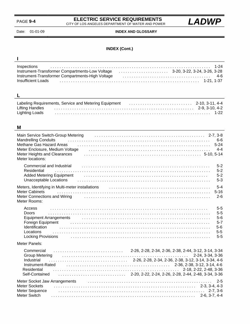
PAGE 9-4 ELECTRIC SERVICE REQUIREMENTS CITY OF LOS ANGELES DEPARTMENT OF WATER AND POWER LADWP
Date: 01-01-09 INDEX AND GLOSSARY
INDEX (Cont.) I
Inspections . . . . . . . . . . . . . . . . . . . . . . . . . . . . . . . . . . . . . . . . . . . . . . . . . . . . . . . . . . . . . . . . . . . . . . . 1-24Instrument-Transformer Compartments-Low Voltage . . . . . . . . . . . . . . . . . . . . . . 3-20, 3-22, 3-24, 3-26, 3-28Instrument-Transformer Compartments-High Voltage . . . . . . . . . . . . . . . . . . . . . . . . . . . . . . . . . . . . . . . 4-6Insufficient Loads . . . . . . . . . . . . . . . . . . . . . . . . . . . . . . . . . . . . . . . . . . . . . . . . . . . . . . . . . . . . . . 1-21, 1-37
L
Labeling Requirements, Service and Metering Equipment . . . . . . . . . . . . . . . . . . . . . . . . . . . . 2-10, 3-11, 4-4Lifting Handles . . . . . . . . . . . . . . . . . . . . . . . . . . . . . . . . . . . . . . . . . . . . . . . . . . . . . . . . . . . . . . 2-9, 3-10, 4-2Lighting Loads . . . . . . . . . . . . . . . . . . . . . . . . . . . . . . . . . . . . . . . . . . . . . . . . . . . . . . . . . . . . . . . . . . . . . 1-22
M
Main Service Switch-Group Metering . . . . . . . . . . . . . . . . . . . . . . . . . . . . . . . . . . . . . . . . . . . . . . . . . 2-7, 3-8Mandrelling Conduits . . . . . . . . . . . . . . . . . . . . . . . . . . . . . . . . . . . . . . . . . . . . . . . . . . . . . . . . . . . . . . . 6-6Methane Gas Hazard Areas . . . . . . . . . . . . . . . . . . . . . . . . . . . . . . . . . . . . . . . . . . . . . . . . . . . . . . . . . . . 5-24Meter Enclosure, Medium Voltage . . . . . . . . . . . . . . . . . . . . . . . . . . . . . . . . . . . . . . . . . . . . . . . . . . . . . . 4-4Meter Heights and Clearances . . . . . . . . . . . . . . . . . . . . . . . . . . . . . . . . . . . . . . . . . . . . . . . . . . . . 5-10, 5-14Meter locations:
Commercial and Industrial . . . . . . . . . . . . . . . . . . . . . . . . . . . . . . . . . . . . . . . . . . . . . . . . . . . . . . . . . 5-2Residential . . . . . . . . . . . . . . . . . . . . . . . . . . . . . . . . . . . . . . . . . . . . . . . . . . . . . . . . . . . . . . . . . . . . . 5-2Added Metering Equipment . . . . . . . . . . . . . . . . . . . . . . . . . . . . . . . . . . . . . . . . . . . . . . . . . . . . . . . 5-2Unacceptable Locations . . . . . . . . . . . . . . . . . . . . . . . . . . . . . . . . . . . . . . . . . . . . . . . . . . . . . . . . . . . 5-3
Meters, Identifying in Multi-meter installations . . . . . . . . . . . . . . . . . . . . . . . . . . . . . . . . . . . . . . . . . . . . . 5-4Meter Cabinets . . . . . . . . . . . . . . . . . . . . . . . . . . . . . . . . . . . . . . . . . . . . . . . . . . . . . . . . . . . . . . . . . . . . 5-16Meter Connections and Wiring . . . . . . . . . . . . . . . . . . . . . . . . . . . . . . . . . . . . . . . . . . . . . . . . . . . . . . . . 2-6Meter Rooms:
Access . . . . . . . . . . . . . . . . . . . . . . . . . . . . . . . . . . . . . . . . . . . . . . . . . . . . . . . . . . . . . . . . . . . . . . 5-5Doors . . . . . . . . . . . . . . . . . . . . . . . . . . . . . . . . . . . . . . . . . . . . . . . . . . . . . . . . . . . . . . . . . . . . . . . . 5-5Equipment Arrangements . . . . . . . . . . . . . . . . . . . . . . . . . . . . . . . . . . . . . . . . . . . . . . . . . . . . . . . . . 5-6Foreign Equipment . . . . . . . . . . . . . . . . . . . . . . . . . . . . . . . . . . . . . . . . . . . . . . . . . . . . . . . . . . . . . . 5-7Identification . . . . . . . . . . . . . . . . . . . . . . . . . . . . . . . . . . . . . . . . . . . . . . . . . . . . . . . . . . . . . . . . . . . 5-6Locations . . . . . . . . . . . . . . . . . . . . . . . . . . . . . . . . . . . . . . . . . . . . . . . . . . . . . . . . . . . . . . . . . . . . . . 5-5Locking Provisions . . . . . . . . . . . . . . . . . . . . . . . . . . . . . . . . . . . . . . . . . . . . . . . . . . . . . . . . . . . . . . 5-5
Meter Panels:
Commercial . . . . . . . . . . . . . . . . . . . . . . . . . . . . . . . 2-26, 2-28, 2-34, 2-36, 2-38, 2-44, 3-12, 3-14, 3-34Group Metering . . . . . . . . . . . . . . . . . . . . . . . . . . . . . . . . . . . . . . . . . . . . . . . . . . . . . . . . 2-24, 3-34, 3-36Industrial . . . . . . . . . . . . . . . . . . . . . . . . . . . . . . . . . . . 2-26, 2-28, 2-34, 2-36, 2-38, 3-12, 3-14, 3-34, 4-6Instrument-Rated . . . . . . . . . . . . . . . . . . . . . . . . . . . . . . . . . . . . . . . . . . . . . . 2-36, 2-38, 3-12, 3-14, 4-6
Residential . . . . . . . . . . . . . . . . . . . . . . . . . . . . . . . . . . . . . . . . . . . . . . . . . . . . . . . . 2-18, 2-22, 2-48, 3-36 Self-Contained . . . . . . . . . . . . . . . . . . . . . . . . . . . . . . 2-20, 2-22, 2-24, 2-26, 2-28, 2-44, 2-48, 3-34, 3-36
Meter Socket Jaw Arrangements . . . . . . . . . . . . . . . . . . . . . . . . . . . . . . . . . . . . . . . . . . . . . . . . . . . . . . . 2-5Meter Sockets . . . . . . . . . . . . . . . . . . . . . . . . . . . . . . . . . . . . . . . . . . . . . . . . . . . . . . . . . . . . . . . 2-3, 3-4, 4-3Meter Sequence . . . . . . . . . . . . . . . . . . . . . . . . . . . . . . . . . . . . . . . . . . . . . . . . . . . . . . . . . . . . . . . . . 2-7, 3-6Meter Switch . . . . . . . . . . . . . . . . . . . . . . . . . . . . . . . . . . . . . . . . . . . . . . . . . . . . . . . . . . . . . . . . 2-6, 3-7, 4-4

LADWP ELECTRIC SERVICE REQUIREMENTS CITY OF LOS ANGELES DEPARTMENT OF WATER AND POWER
PAGE 9-5
INDEX AND GLOSSARY Date 01-01-04
INDEX (Cont.) M (Cont.)
Meter Wiring Raceway . . . . . . . . . . . . . . . . . . . . . . . . . . . . . . . . . . . . . . . . . . . . . . . . . . . . . . . . . . . . . . . 3-6Mobile Home (Trailer) Post. . . . . . . . . . . . . . . . . . . . . . . . . . . . . . . . . . . . . . . . . . . . . . . . . . . . . . . . . . . . . 2-48Motors, Single-Phase and Three-Phase . . . . . . . . . . . . . . . . . . . . . . . . . . . . . . . . . . . . . . . . . . . . . . . . . . . 1-21
O
Overhead Services, Design and Installation Guide . . . . . . . . . . . . . . . . . . . . . . . . . . . . . . . . . . . . . . . . . 7-1
Service Drops:
Allowable Length . . . . . . . . . . . . . . . . . . . . . . . . . . . . . . . . . . . . . . . . . . . . . . . . . . . . . . . . . . . . 101
Attachments . . . . . . . . . . . . . . . . . . . . . . . . . . . . . . . . . . . . . 7-9, 7-17, 7-18, 7-20, 7-22, 7-240, 7-26Clearances:
Buildings, Vertical Clearances above . . . . . . . . . . . . . . . . . . . . . . . . . . . . . . . . . . . . . . . . . . . 7-4Doors, Exits, Windows, Fire Escapes, Stairs . . . . . . . . . . . . . . . . . . . . . . . . . . . . . . . . . . . . . 7-5Other Conductors . . . . . . . . . . . . . . . . . . . . . . . . . . . . . . . . . . . . . . . . . . . . . . . . . . . . . . . . . 7-9Railroad Tracks . . . . . . . . . . . . . . . . . . . . . . . . . . . . . . . . . . . . . . . . . . . . . . . . . . . . . . . . . . 7-6Signs . . . . . . . . . . . . . . . . . . . . . . . . . . . . . . . . . . . . . . . . . . . . . . . . . . . . . . . . . . . . . . . . . . 7-9Swimming Pools . . . . . . . . . . . . . . . . . . . . . . . . . . . . . . . . . . . . . . . . . . . . . . . . . . . . . . . . . . 7-8Walkways, Driveways and Thoroughfares-Public and Private Property . . . . . . . . . . . . . . . . . 7-6
Number Supplied . . . . . . . . . . . . . . . . . . . . . . . . . . . . . . . . . . . . . . . . . . . . . . . . . . . . . . . . . . . . 7-2
Service Heads:
Busway Requirements . . . . . . . . . . . . . . . . . . . . . . . . . . . . . . . . . . . . . . . . . . . . . . . . 7-15, 3-3, 3-48Locations . . . . . . . . . . . . . . . . . . . . . . . . . . . . . . . . . . . . . . . . . . . . . . . . . . . . . . . . . . . . . . . . . 7-15Replacement or additional . . . . . . . . . . . . . . . . . . . . . . . . . . . . . . . . . . . . . . . . . . . . . . . . . . . . . . 7-16Riser Conduits . . . . . . . . . . . . . . . . . . . . . . . . . . . . . . . . . . . . . . . . . . . . . . . . . . . . . . . . . . . . . . 7-14Service Entrance Conductors . . . . . . . . . . . . . . . . . . . . . . . . . . . . . . . . . . . . . . . . . . . . . . . . . . . 7-14
Service Pole, Metal Pole, Permanent/Temporary . . . . . . . . . . . . . . . . . . . . . . . . . . . . . . . . . . . . . . . . 7-26Service Pole, Wood, Permanent/Temporary . . . . . . . . . . . . . . . . . . . . . . . . . . . . . . . . . . . . . . . . . . . 7-24Service Pole, Temporary (1 Year Maximum Service) . . . . . . . . . . . . . . . . . . . . . . . . . . . . . . . . . . . . . 7-22
P
Parallel-Generating Systems: 8-1
Data Required for Design . . . . . . . . . . . . . . . . . . . . . . . . . . . . . . . . . . . . . . . . . . . . . . . . . . . . . . . . . 8-2Disconnection of Customer’s Energy Source:
General . . . . . . . . . . . . . . . . . . . . . . . . . . . . . . . . . . . . . . . . . . . . . . . . . . . . . . . . . . . . . . . . . . . . 8-4Notification . . . . . . . . . . . . . . . . . . . . . . . . . . . . . . . . . . . . . . . . . . . . . . . . . . . . . . . . . . . . . . . . . . 8-5
Electric Rates . . . . . . . . . . . . . . . . . . . . . . . . . . . . . . . . . . . . . . . . . . . . . . . . . . . . . . . . . . . . . . . . . . 8-3Generators . . . . . . . . . . . . . . . . . . . . . . . . . . . . . . . . . . . . . . . . . . . . . . . . . . . . . . . . . . . . . . . . . . . . . 8-9Generator Disconnects:
General . . . . . . . . . . . . . . . . . . . . . . . . . . . . . . . . . . . . . . . . . . . . . . . . . . . . . . . . . . . . . . . . . . . . 8-5Access . . . . . . . . . . . . . . . . . . . . . . . . . . . . . . . . . . . . . . . . . . . . . . . . . . . . . . . . . . . . . . . . . . . . 8-5

PAGE 9-6 ELECTRIC SERVICE REQUIREMENTS CITY OF LOS ANGELES DEPARTMENT OF WATER AND POWER LADWP
Date: 01-01-10 INDEX AND GLOSSARY
INDEX (Cont.) P (Cont.)
Parallel-Generating Systems (Cont.) 8-1
Informational Signs . . . . . . . . . . . . . . . . . . . . . . . . . . . . . . . . . . . . . . . . . . . . . . . . . . . . . . . . . . . . . . 8-6Inspections . . . . . . . . . . . . . . . . . . . . . . . . . . . . . . . . . . . . . . . . . . . . . . . . . . . . . . . . . . . . . . . . . . . 8-4Interconnection Agreements . . . . . . . . . . . . . . . . . . . . . . . . . . . . . . . . . . . . . . . . . . . . . . . . . . . . . . . 8-3Interconnection Costs . . . . . . . . . . . . . . . . . . . . . . . . . . . . . . . . . . . . . . . . . . . . . . . . . . . . . . . . . . . . 8-3Interconnection Schematics, Typical:
Department-Owned Transformers . . . . . . . . . . . . . . . . . . . . . . . . . . . . . . . . . . . . . . . . . . . . . . . 8-12Customer-Owned Transformers . . . . . . . . . . . . . . . . . . . . . . . . . . . . . . . . . . . . . . . . . . . . . . . . . 8-14
Inverters . . . . . . . . . . . . . . . . . . . . . . . . . . . . . . . . . . . . . . . . . . . . . . . . . . . . . . . . . . . . . . . . . . . . . . 8-9Liability . . . . . . . . . . . . . . . . . . . . . . . . . . . . . . . . . . . . . . . . . . . . . . . . . . . . . . . . . . . . . . . . . . . . . . . 8-4Maintenance . . . . . . . . . . . . . . . . . . . . . . . . . . . . . . . . . . . . . . . . . . . . . . . . . . . . . . . . . . . . . . . . . . . 8-7Metering . . . . . . . . . . . . . . . . . . . . . . . . . . . . . . . . . . . . . . . . . . . . . . . . . . . . . . . . . . . . . . . . . . . . . . 8-4Operating Requirements . . . . . . . . . . . . . . . . . . . . . . . . . . . . . . . . . . . . . . . . . . . . . . . . . . . . . . . . . . 8-3Protective Schemes . . . . . . . . . . . . . . . . . . . . . . . . . . . . . . . . . . . . . . . . . . . . . . . . . . . . . . . . . . . . . 8-6Records . . . . . . . . . . . . . . . . . . . . . . . . . . . . . . . . . . . . . . . . . . . . . . . . . . . . . . . . . . . . . . . . . . . . . . 8-7Specifications . . . . . . . . . . . . . . . . . . . . . . . . . . . . . . . . . . . . . . . . . . . . . . . . . . . . . . . . . . . . . . . . . . 8-8Telemetry . . . . . . . . . . . . . . . . . . . . . . . . . . . . . . . . . . . . . . . . . . . . . . . . . . . . . . . . . . . . . . . . . . . . . . 8-7Testing and Evaluation . . . . . . . . . . . . . . . . . . . . . . . . . . . . . . . . . . . . . . . . . . . . . . . . . . . . . . . . . . . 8-8Transformer Requirements . . . . . . . . . . . . . . . . . . . . . . . . . . . . . . . . . . . . . . . . . . . . . . . . . . . . . . . . 8-3
Pedestal, Meter and Service, Commercial Services . . . . . . . . . . . . . . . . . . . . . . . . . . . . . . . . . . . . . . . . 2-44Plans, Design and Approval . . . . . . . . . . . . . . . . . . . . . . . . . . . . . . . . . . . . . . . . . . . . . . . . . . . . . . . . . . . 1-8Post, Meter and Service, Mobile Home (Trailer) Services . . . . . . . . . . . . . . . . . . . . . . . . . . . . . . . . . . . . 2-48Protection, Service Equipment (Barrier Posts) . . . . . . . . . . . . . . . . . . . . . . . . . . . . . . . . . . . . . . . . . . . . . 5-14Pull Boxes, Underground Service Terminations . . . . . . . . . 2-15, 2-16, 2-18, 2-20, 2-22, 2-24, 2-36, 2-44, 2-48Pull sections, Underground Service Terminations . . . . . . . . . . . . . . . . . . . . . . . . . . . . . . . 3-9, 3-44, 3-46, 4-18
R
Remote Metering . . . . . . . . . . . . . . . . . . . . . . . . . . . . . . . . . . . . . . . . . . . . . . . . . . . . . . . . . . . . . . . . 2-34, 3-6Risers, Conduit . . . . . . . . . . . . . . . . . . . . . . . . . . . . . . . . . . . . . . . . . . . . . . . . . . . . . . . . . . . . . . . . . . . . 6-6
S
Safety Barrier, Pull Section . . . . . . . . . . . . . . . . . . . . . . . . . . . . . . . . . . . . . . . . . . . . . . . . . . 2-12, 3-44, 3-46Safety-Socket Meter Panel . . . . . . . . . . . . . . . . . . . . . . . . . . . . . . . . . . . . . . . . . . . . . . . . . . . . . . . . 2-26, 2-28Sealing Requirements (panels) . . . . . . . . . . . . . . . . . . . . . . . . . . . . . . . . . . . . . . . . . . . . . . . . . 2-9, 3-10, 4-3Self-Generation Systems . . . . . . . . . . . . . . . . . . . . . . . . . . . . . . . . . . . . . . . . . . . . . . . . . . . . . . . . . . 1-32, 8-1Service Disconnects:
Generator Disconnects . . . . . . . . . . . . . . . . . . . . . . . . . . . . . . . . . . . . . . . . . . . . . . . . . . . . . . . . . . . . 8-5 Locking Provisions . . . . . . . . . . . . . . . . . . . . . . . . . . . . . . . . . . . . . . . . . . . . . . . . . . 2-7, 3-7, 3-8, 4-3, 8-5 Meter Switch . . . . . . . . . . . . . . . . . . . . . . . . . . . . . . . . . . . . . . . . . . . . . . . . . . . . . . . . . . . . . . . 2-6, 3-7, 4-3
Service Main Switch (Group Metering) . . . . . . . . . . . . . . . . . . . . . . . . . . . . . . . . . . . . . . . . . . . . . . . . 2-7, 3-8Service Drops, Overhead Services . . . . . . . . . . . . . . . . . . . . . . . . . . . . . . . . . . . . . . . . . . . . . . . . . . . . . 7-2Service Entrance Conductors . . . . . . . . . . . . . . . . . . . . . . . . . . . . . . . . . . . . . . . . . . . . . . . . . . . . . . . . . 7-14

LADWP ELECTRIC SERVICE REQUIREMENTS CITY OF LOS ANGELES DEPARTMENT OF WATER AND POWER
PAGE 9-7
INDEX AND GLOSSARY Date 01-01-10
INDEX (Cont.) S (Cont.)
Service Heads . . . . . . . . . . . . . . . . . . . . . . . . . . . . . . . . . . . . . . . . . . . . . . . . . . . . . . . . . . . . . . . . . . . . . 7-14Service Head locations . . . . . . . . . . . . . . . . . . . . . . . . . . . . . . . . . . . . . . . . . . . . . . . . . . . . . . . . . . . . . . . 7-15Service Locations . . . . . . . . . . . . . . . . . . . . . . . . . . . . . . . . . . . . . . . . . . . . . . . . . . . . . . . . . . . . . . . . . . 6-2Service Main Switch-Group Metering . . . . . . . . . . . . . . . . . . . . . . . . . . . . . . . . . . . . . . . . . . . . . . . . . 2-7, 3-8Service Pedestal, Commercial . . . . . . . . . . . . . . . . . . . . . . . . . . . . . . . . . . . . . . . . . . . . . . . . . . . . . . . . 2-44Service Planning Offices . . . . . . . . . . . . . . . . . . . . . . . . . . . . . . . . . . . . . . . . . . . . . . . . . . . . . . . . . . . . 1-4Service Pole, Permanent . . . . . . . . . . . . . . . . . . . . . . . . . . . . . . . . . . . . . . . . . . . . . . . . . . . . . . . . 7-24, 7-26Service Pole, Temporary . . . . . . . . . . . . . . . . . . . . . . . . . . . . . . . . . . . . . . . . . . . . . . . . . . . . . . . . . . . . . 7-22Service Post, Mobile Home (Trailer) Services . . . . . . . . . . . . . . . . . . . . . . . . . . . . . . . . . . . . . . . . . . . . . 2-48Service Voltages, Standard . . . . . . . . . . . . . . . . . . . . . . . . . . . . . . . . . . . . . . . . . . . . . . . . . . . . . . . . . . . 1-25Short Circuit Current . . . . . . . . . . . . . . . . . . . . . . . . . . . . . . . . . . . . . . . . . . . . . . . . . . . . . . . . . . . . . . . . . . . 1-28Solar Generating Systems . . . . . . . . . . . . . . . . . . . . . . . . . . . . . . . . . . . . . . . . . . . . . . . . . . . . . . 8-9, 8-10, 8-11Swabbing Conduits . . . . . . . . . . . . . . . . . . . . . . . . . . . . . . . . . . . . . . . . . . . . . . . . . . . . . . . . . . . . . . . . . . . 6-6Swimming Pool Clearances . . . . . . . . . . . . . . . . . . . . . . . . . . . . . . . . . . . . . . . . . . . . . . . . . . . . . . . . . . 7-8Switchboards, Low-Voltage:
Approvals . . . . . . . . . . . . . . . . . . . . . . . . . . . . . . . . . . . . . . . . . . . . . . . . . . . . . . . . . . . . . . . . . . . . . . 3-3Barriers . . . . . . . . . . . . . . . . . . . . . . . . . . . . . . . . . . . . . . . . . . . . . . . . . . . . . . . . . . . . . . . . . . . . . . . 3-4Hinged Meter Panel . . . . . . . . . . . . . . . . . . . . . . . . . . . . . . . . . . . . . . . . . . . . . . . . . . . . . . . . . 3-16, 3-18, Instrument-Transformer Compartments . . . . . . . . . . . . . . . . . . . . . . . . . . . . . 3-20, 3-22, 3-24, 3-26, 3-28Outdoor (weatherproof) . . . . . . . . . . . . . . . . . . . . . . . . . . . . . . . . . . . . . . . . . . . . . . . . . . . . . . . . . . . 3-38Pull Sections . . . . . . . . . . . . . . . . . . . . . . . . . . . . . . . . . . . . . . . . . . . . . . . . . . . . . . . . . . . 3-9, 3-44, 3-46
Self-Contained Meters . . . . . . . . . . . . . . . . . . . . . . . . . . . . . . . . . . . . . . . . . . . . . . . . . . . . . . . 3-4, 3-34, 3-36Switchgear, Medium-Voltage:
Approvals . . . . . . . . . . . . . . . . . . . . . . . . . . . . . . . . . . . . . . . . . . . . . . . . . . . . . . . . . . . . . . . . . . . . . 4-2Compartment Barriers . . . . . . . . . . . . . . . . . . . . . . . . . . . . . . . . . . . . . . . . . . . . . . . . . . . . . . . . . . . 4-2Current-Transformer Mounting Base . . . . . . . . . . . . . . . . . . . . . . . . . . . . . . . . . . . . . . . . . . . . . . . . . 4-16Instrument-Transformer Compartments . . . . . . . . . . . . . . . . . . . . . . . . . . . . . . . . . . . . . . . . . . . . 4-6, 4-15Pull Sections . . . . . . . . . . . . . . . . . . . . . . . . . . . . . . . . . . . . . . . . . . . . . . . . . . . . . . . . . . . . . . . . . . . 4-18Voltage-Transformer Mounting Rail . . . . . . . . . . . . . . . . . . . . . . . . . . . . . . . . . . . . . . . . . . . . . . . . . . 4-16Weatherproof Enclosures . . . . . . . . . . . . . . . . . . . . . . . . . . . . . . . . . . . . . . . . . . . . . . . . . . . . . . . . . 4-4
T
Temporary Services . . . . . . . . . . . . . . . . . . . . . . . . . . . . . . . . . . . . . . . . . . . . . . . 1-29, 5-18, 7-22, 7-24, 7-26Terminating Enclosures-Low Voltage . . . . 2-15, 2-16, 2-18, 2-20, 2-22, 2-24, 2-36, 2-44, 2-48, 3-9, 3-44, 3-46Terminating Enclosures-Medium Voltage . . . . . . . . . . . . . . . . . . . . . . . . . . . . . . . . . . . . . . . . . . . . . . . . 4-18Terminating Facilities, Supply Cable, Pressure Type . . . . . . . . . . . . . . . . . . . . . . . . . . 2-20, 2-24, 2-44, 2-48Terminating Facilities, Supply Cable, Stud-Type . . . . . . . . . . . . . . . . 2-12, 2-16, 2-40, 2-42, 3-44, 3-46, 4-18Test-Bypass Blocks . . . . . . . . . . . . . . . . . . . . . . . . . . . . . . . . . . . . . . . . . . . . . . . . . . . . . . . . . . . . . . . . . 2-32Totalizing Services . . . . . . . . . . . . . . . . . . . . . . . . . . . . . . . . . . . . . . . . . . . . . . . . . . . . . . . . . . . . . . . . . . 3-5Transformers:
Access and Clearances . . . . . . . . . . . . . . . . . . . . . . . . . . . . . . . . . . . . . . . . . . . . . . . . . . . . . . . . . . 1-36Indoor Installations . . . . . . . . . . . . . . . . . . . . . . . . . . . . . . . . . . . . . . . . . . . . . . . . . . . . . . . . . . . . . . . 1-35Outdoor Installations-Enclosed Concrete Pad . . . . . . . . . . . . . . . . . . . . . . . . . . . . . . . . . . . . . . . . . . 1-35Pad-Mounted Installations . . . . . . . . . . . . . . . . . . . . . . . . . . . . . . . . . . . . . . . . . . . . . . . . . . . . . . . . . 1-35Pole-Mounted Installations . . . . . . . . . . . . . . . . . . . . . . . . . . . . . . . . . . . . . . . . . . . . . . . . . . . . . . . . 1-34Standard Installations . . . . . . . . . . . . . . . . . . . . . . . . . . . . . . . . . . . . . . . . . . . . . . . . . . . . . . . . . . . . 1-36Underground Vault Installations . . . . . . . . . . . . . . . . . . . . . . . . . . . . . . . . . . . . . . . . . . . . . . . . . . . . . 1-35

PAGE 9-8 ELECTRIC SERVICE REQUIREMENTS CITY OF LOS ANGELES DEPARTMENT OF WATER AND POWER LADWP
Date: 01-01-09 INDEX AND GLOSSARY
INDEX (Cont.) V
Voltage Transformers . . . . . . . . . . . . . . . . . . . . . . . . . . . . . . . . . . . . . . . . . . . . . . . . . . . . . . . . 4-7, 4-8, 4-16 W
Weatherproof Enclosures . . . . . . . . . . . . . . . . . . . . . . . . . . . . . . . . . . . . . . . . . . . . . . . . . . . . . . . . . 3-38, 4-4Welders . . . . . . . . . . . . . . . . . . . . . . . . . . . . . . . . . . . . . . . . . . . . . . . . . . . . . . . . . . . . . . . . . . . . . . . . . 1-22Wiring and Connections, Meter Sockets . . . . . . . . . . . . . . . . . . . . . . . . . . . . . . . . . . . . . . . . . . . . . . . . . 2-6Working Space and Clearances:
0-600 Volt Installations . . . . . . . . . . . . . . . . . . . . . . . . . . . . . . . . . . . . . . . . . . . . . . . . . . . . . . . . . . . . 5-10601-4800 Volt Installations . . . . . . . . . . . . . . . . . . . . . . . . . . . . . . . . . . . . . . . . . . . . . . . . . . . . . . . . . 5-14
X
X-Ray Equipment Loads . . . . . . . . . . . . . . . . . . . . . . . . . . . . . . . . . . . . . . . . . . . . . . . . . . . . . . . . . . . . . 1-22

LADWP ELECTRIC SERVICE REQUIREMENTS CITY OF LOS ANGELES DEPARTMENT OF WATER AND POWER
PAGE 9-9
INDEX AND GLOSSARY Date 01-01-09
EUSERC/ESR CROSS REFERENCE AND ACCEPTABILITY INDEX The Department of Water and Power’s (Department) Electric Service Requirements (ESR) are in general agreement with the service and metering equipment requirements of the Electric Utility Service Equipment Requirements Committee (EUSERC). Where differences occur between the Department’s ESR and the EUSERC requirements, the ESR requirement specified shall take precedence.
EUSER ESR A/C EUSER ESR A/C EUSER ESR A/C 301 2-20 A 320 3-22 A 343 2-16 A
301A N/P U 321 3-24 A 343A N/P U 302 N/P U 322 3-26 A 344 2-15 C
302A 2-22 A 323 N/P U 345 3-44 A 302B N/P U 324 3-28 A 346 N/P U
303 N/P U 325 3-12 C 347 2-12 C 304 2-26 A 326 3-14 C 348 3-40 C 305 2-26 A 327 3-44 A 349 3-48 C 306 3-36 A 328A 2-40 A 351 N/P U 307 2-48 A 328B 2-41 C 353 3-36 A 308 2-44 A 329A 2-42 A 354 3-38 A 309 N/P U 329B 2-43 C 401 4-6 C 311 2-32 A 330 3-30 A 404 N/P NA 312 N/P A 331 3-32 A 407 4-16 C 313 2-38 A 332 3-16 C 408 4-10 A 314 2-36 A 333 N/P U 409 NA N/P 315 2-18 A 336 N/P U 411 4-12 A 316 N/P U 337 N/P NA 414 NA N/P 317 N/P U 338 N/P U 416 NA N/P 318 N/P U 339 2-34 A 418 4-18 A 319 3-20 A 342 2-24 A 420 NA U
Note: Changes in the table above reflect revisions to the 2004 publication of the EUSERC book. Table Codes:
N/P No equivalent ESR page A/C Acceptance Codes:
A Department accepts EUSERC drawing. U Department does not accept EUSERC drawing. C Department accepts EUSERC drawing with some variations – consult ESR page for requirements. NA Not applicable to the Department’s service area
Note: See Page 9-10 for a listing of the differences between EUSERC drawings and Department ESR pages.
Indicates latest revision
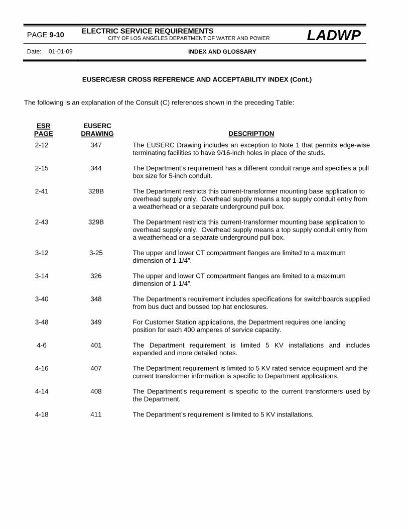
PAGE 9-10 ELECTRIC SERVICE REQUIREMENTS CITY OF LOS ANGELES DEPARTMENT OF WATER AND POWER LADWP
Date: 01-01-09 INDEX AND GLOSSARY
EUSERC/ESR CROSS REFERENCE AND ACCEPTABILITY INDEX (Cont.) The following is an explanation of the Consult (C) references shown in the preceding Table:
ESR PAGE
EUSERC DRAWING
DESCRIPTION
2-12 347 The EUSERC Drawing includes an exception to Note 1 that permits edge-wise terminating facilities to have 9/16-inch holes in place of the studs.
2-15 344 The Department’s requirement has a different conduit range and specifies a pull
box size for 5-inch conduit.
2-41 328B The Department restricts this current-transformer mounting base application to overhead supply only. Overhead supply means a top supply conduit entry from a weatherhead or a separate underground pull box.
2-43 329B The Department restricts this current-transformer mounting base application to
overhead supply only. Overhead supply means a top supply conduit entry from a weatherhead or a separate underground pull box.
3-12 3-25 The upper and lower CT compartment flanges are limited to a maximum
dimension of 1-1/4”.
3-14 326 The upper and lower CT compartment flanges are limited to a maximum dimension of 1-1/4”.
3-40 348 The Department’s requirement includes specifications for switchboards supplied
from bus duct and bussed top hat enclosures.
3-48 349 For Customer Station applications, the Department requires one landing position for each 400 amperes of service capacity.
4-6 401 The Department requirement is limited 5 KV installations and includes
expanded and more detailed notes.
4-16 407 The Department requirement is limited to 5 KV rated service equipment and the current transformer information is specific to Department applications.
4-14 408 The Department’s requirement is specific to the current transformers used by
the Department.
4-18 411 The Department’s requirement is limited to 5 KV installations.

LADWP ELECTRIC SERVICE REQUIREMENTS CITY OF LOS ANGELES DEPARTMENT OF WATER AND POWER
PAGE 9-11
INDEX AND GLOSSARY Date 01-01-09
GLOSSARY The following terms are used through these electric service requirements: Accessible: Capable of being reached conveniently and quickly during normal business hours for construction, operation, maintenance, inspection or testing without requiring Department personnel to climb over or remove obstacles; or to obtain special permission or security clearances. Some installations may require 24-hour access. Across-the-line starting current: The electrical current required by a motor at starting with full line voltage and frequency, and with normally driven load mechanically connected. A stop-ammeter having not more than 15-percent over swing, or an oscillograph, shall be used when it is necessary to determine the starting current. Values indicated by the oscillograph during the first 10 cycles following energizing of the motor shall be disregarded. ANSI: American National Standards Institute Application: A request for electric service connection made to a Department Customer Service Branch Office. Approved: The facilities installed by the customer are acceptable meets with the Department's service requirements, Rules, and policies. AWG: American Wire Gauge Barriers: See Isolating Barriers Building: A structure standing alone, used for or intended for supporting or sheltering any use or occupancy, and requiring a separate permit by the permitting agency for each separate building or structure. Bus, Live: Bus bars which are electrically energized. Busway (Bus Duct): A raceway structure enclosing bus bars and equipped used to connect metering equipment to the point of service. Cablebus: A raceway structure used in Customer Station installations to enclose the Department's service supply conductors. The structure is furnished and installed without supply conductors by the customer in accordance with the Department's specifications. Commercial Station: An indoor or enclosed outdoor transformer facility installed on a customer's premises and supplied from the Department's 4800-volt electric system. Conductors, Service Entrance: The conductors installed by the customer from the service point to the service and metering equipment and conforming to the City of Los Angeles electric code or other applicable governing code. Conductors, Service Supply: The conductors installed by the Department from the supply source to the customer's service point. Conduit: A pipe manufactured of Department-approved materials, whether direct buried or concrete encased, used to enclose electric conductors. Current Transformer: An instrument transformer designed for use in the measurement of electrical current. Customer: The owner, whether a person or business association, or any person or agency authorized to represent the owner's interests.

PAGE 9-12 ELECTRIC SERVICE REQUIREMENTS CITY OF LOS ANGELES DEPARTMENT OF WATER AND POWER LADWP
Date: 01-01-05 INDEX AND GLOSSARY
GLOSSARY (Cont.) Customer Generator: A device installed and operated by a customer to supply electric energy to all, or part of, a customer's load. See "Stand-Alone Generator" and "Parallel Generator". Department: The Los Angeles Department of Water and Power. Dog House: A common term for a weatherproof enclosure built by the customer on the exterior of a building or other structure and used to enclose indoor service and metering equipment. Emergency Generator: A customer generator used to supply electrical energy to all, or part of, a customer's load when the Department's electric system has been de-energized. See "Customer Generator". EXO: Any assembled service wiring installation which does not use a switchboard. Final Grade: The ground surface elevation after paving and improvements have been completed. First Floor: The building floor that is closest to the elevation of, and above, the ground level. Housekeeping Pad: A raised portion of the floor or a raised concrete foundation (pad) installed beneath service and metering equipment and generally intended to keep the equipment out of standing water. Industrial Station: A transformer installation located on the customer's premises and supplied from the Department's 34,500-volt electric system. Inspection Authority: Those City, County, State, and Federal agencies responsible for issuing electrical permits, making inspections of the customer's electrical wiring system, and for notifying the Department if such system meets all applicable codes and ordinances and is ready for service. Instrument Transformer: A transformer that produces in its secondary circuit, a definite and known proportion of the current or voltage in its primary circuit. Intermittent Duty Operation: A service characteristic where the load conditions are regularly repeated or demand alternating operation. A motor operation is considered to be intermittent if it is controlled by automatic switches (Actuated by pressure, liquid level, temperature, or other similar means), or the operating cycle has more than four starts in any 8-hour period and is not normally manually controlled. Isolating Barrier: A partition of either conductive or nonconductive material used to mechanically isolate internal compartments or sections from other integral compartments or sections of the enclosure. Metered Circuits: Those conductors extending from the secondary side of the meter to the customer's load circuits or outlets connected to such circuits. Meter, Instrument-Transformer Rated: An electrical meter that is connected to a circuit through instrument transformers (i.e., current-transformers and, when required, voltage transformers) and used to accurately measure and register all the electrical energy consumed in the circuit. Meter Room: A weatherproof, fully illuminated room, provided at the customer's option and approved by the Department. Meter Panel: A panel used exclusively for mounting meter sockets and associated equipment.
LADWP ELECTRIC SERVICE REQUIREMENTS CITY OF LOS ANGELES DEPARTMENT OF WATER AND POWER
PAGE 9-13
INDEX AND GLOSSARY Date 01-01-05
GLOSSARY (Cont.) Meter, Self-Contained: An electrical meter that is connected directly into a circuit and is used to accurately measure and register all the electrical energy consumed in the circuit. Operating Convenience: The utilization, under certain conditions, of facilities or practices not usually employed which contribute to the overall efficiency of the Department's system. Parallel Generator: A customer generator used to supply electrical energy to all, or part of, a customer's load and operated, or switched, in parallel with the Department's electric system. See "Customer Generator". Pull Box: A wall-mounted, fully-enclosed, metal enclosure used to connect the service supply conductors to the service entrance conductors. Pull Section: A floor-standing, open-bottomed, metal enclosure used to connect the service supply conductors to the service entrance conductors. Raceway, Overhead: The conduit or sealable wiring enclosure from the service head to the meter socket box, current-transformer box, instrument-transformer compartment, or disconnect device used, that is used to enclose the service entrance conductors. Raceway, Underground: The conduit or sealable enclosure between the terminating enclosure and the meter socket box, current-transformer box, instrument-transformer compartment, or disconnect device, that is used to enclose the service entrance conductors. Rules: The document, approved by the General Manager and the Board of Water and Power Commissioners, governing water and electric service in the Department and Water and Power service territory. Sealing Ring: A device, supplied by the electrical equipment manufacturer, used to hold socket type meters in place with provisions for installing the Department's sealing devices. Sealing Rings, Security: A heavy-duty sealing ring, supplied by the Department, incorporating an integrated a barrel-lock device. Security Area: Any area of a premises not readily available to public access, or requiring special permission or security clearances for access. Self-Generation: See Parallel Generator Service Drop: The Department's overhead conductors extending from the Department's pole line to the point of attachment on the building or structure. Service Entrance Conductors, Overhead: All conductors (including bus or cable) installed by the customer from the service equipment to the point of connection with the Department's service drop conductors. Service Entrance Conductors, Underground: All conductors (including bus or cable installed by the customer from the service equipment to the point of connection with the Department's service lateral conductors. Service Lateral: The span of conductors installed underground in conduit by the Department from a supply source to an approved terminating enclosure. Service Location: The place on the customer's property line where the Department-installed conduits connect to the conduits specified by the Department and installed by the customer.
PAGE 9-14 ELECTRIC SERVICE REQUIREMENTS CITY OF LOS ANGELES DEPARTMENT OF WATER AND POWER LADWP
Date: 01-01-05 INDEX AND GLOSSARY
GLOSSARY (Cont.) Service Point: The location of connection between the Department's facilities and the customer's premises wiring. Stand-Alone Generator: A customer generator used to supply electrical energy to all of, or part of, a customer's load; isolated from the Department's electric system with a non-paralleling switching arrangement, and using the Department's electric system as a standby service. See "Customer-Owned Generators". Switchboard Service Section: A floor-standing, metal enclosure used to terminate service conductor and having provisions for the Department's electric meters and associated equipment, and containing the customer's meter switch. Switchboard, specially Engineered: A switchboard that does not conform to the standard switchboard design and includes one or more of the following conditions: (1) where the service exceeds 600 volts; (2) where the service voltage is 3∅ 3-wire; (3) where the meter switch rating exceeds the ampacity of the standard service section; (4) where the instrument-transformer compartment is supplied from a pull section located below the section (bottom-feed); (5) where multiple-metering sections are used; (6) where recessed meter panels are used. Switchboard, Standard: An electrical switchboard with an instrument-transformer compartment and hinged meter panels, and the customer's meter switch. Switch, Service Main: The breaker, fused-switch, or other approved disconnecting means with over-current protection located on the line side of two or more meters sockets. Switch, Meter: The circuit breaker, fuse-switch, or other approved disconnecting means with over-current protection located on the load side of a meter and controlling all of, and only, the energy registered by the meter (new sequence). The “switch” may consist of up to a maximum of six disconnect devices grouped at one location. Terminating Enclosure: A Department-approved enclosure (i.e., pull box or pull section, or bussed switchboard extension) installed at the underground point of service delivery and used for terminating the Department's service conductors and for joining the conductors to the customers service entrance conductors. Test-Bypass Disconnect Facilities (Test-Blocks): An assembly used in conjunction with a self-contained meter socket and designed to allow the Department to de-energize the meter socket without disconnecting service to the customer. Test Switch: An a device incorporating an arrangement of small knife switches connected in the secondary instrument-transformer circuit between the instrument transformers and the associated meter. The test switch is safety device installed by the Department and used to isolate the meter from the instrument transformers. Test Perch: A bracket designed for mounting the Department's test switch. Voltage Transformer: An instrument transformer designed for use in the measurement of voltage.