vermont utilities electric service requirements manual · pdf filevermont utilities electric...
TRANSCRIPT

Revised 11/07/14
VERMONT UTILITIES ELECTRIC SERVICE
REQUIREMENTS MANUAL
INDEX OF UTILITIES
I. GENERAL INFORMATION
II. GENERAL REQUIREMENTS FOR SERVICE
III. STANDARD SERVICE CHARACTERISTICS
IV. SERVICES (UNDER 600 VOLTS)
V. PRIMARY AND SECONDARY LINE EXTENSIONS
VI. SERVICE ENTRANCE
VII. METERING
VIII. CUSTOMER EQUIPMENT
IX. GROUNDING
X. GLOSSARY
TABLE OF CONTENTS
INDEX OF DRAWINGS

Revised 11/07/14
VERMONT UTILITIES
ELECTRIC SERVICE REQUIREMENTS
MANUAL
The Vermont Utilities Electric Service Requirements manual is produced by a voluntary association
of electric utilities for use as a guide in constructing electric service facilities. The utilities that produced
the manual, and the utilities that use the manual, are not responsible, as an association, for the accuracy
or application of the information contained within. The responsibility for the accuracy or application of
the information contained within remains with the individual utility. The manual is intended to meet the
minimum requirements of the National Electric Code and the National Electric Safety Code. To some
degree the minimum requirements are exceeded for the purpose of simplifying construction and
maintenance. For any questions not answered in the manual contact the serving utility.
Certain utilities listed below have not adopted this manual. Those utilities are listed below only to
complete this manual as a reference; the instructions contained in the manual are not applicable to those
utilities. Please contact those utilities for alternative instructions. The utilities that have not adopted this
manual are indicated by the phrase (Not Adopted) next to the utility’s name.
The producers of this manual meet regularly to update and correct this manual. Revisions
are issued annually. To submit any updates, corrections or additions please submit a
marked up change, with supporting information, to our Secretary, Randy Schramm, GMP
357 South Road, E. Arlington, VT 05252.
E-mail [email protected]
Barton Village, Inc. (Adopted) P.O. Box 519
Barton, VT 05822
(802) 525-4747
Communities served in part:
Barton
Brownington
Charleston
Irasburg
Sutton
Westmore
Burlington Electric Department (BED) (Not Adopted) 585 Pine Street
Burlington, VT 05401-4891
(802) 658-0300
Community served: Burlington

Revised 11/07/14
Enosburg Falls Electric Department (Adopted) 42 Village Drive
Enosburg Falls, VT 05450
(802) 933-4443
Communities served in part:
Bakersfield
Berkshire
Enosburg
Fairfield
Sheldon
Green Mountain Power Corporation (GMP) (Adopted) Corporate Headquarters
163 Acorn Lane
Colchester, VT 05446
(802) 864-5731
For outages, service connections, customer service, billing, and other related business questions, please
call: (888) 835-4672
GMP BRADFORD SERVICE CENTER (located on VT 25) 339 Waits River Road
Bradford, VT 05033
Communities served in whole or in part:
Bradford
Fairlee
Newbury
Norwich
Strafford
Thetford
Vershire
West Fairlee
GMP BRATTLEBORO SERVICE CENTER (located on VT 30) P.O. Box 598
455 West River Road
Brattleboro, VT 05302
Communities served in whole or in part:
Brattleboro
Brookline
Dover
Dummerston
Guilford
Jamaica
Marlboro
Newfane
Stratton
Townshend
Vernon
Wardsboro

Revised 11/07/14
GMP COLCHESTER SERVICE CENTER 163 Acorn Lane
Colchester, VT 05446
Communities served in whole or in part:
Addison
Bolton
Charlotte
Colchester
Essex
Ferrisburg
Hinesburg
Huntington
Jericho
Monkton
New Haven
Panton
Richmond
Sherlburne South Burlington
Starksboro
Vergennes
Waltham
Williston
Winooski
GMP MIDDLEBURY SERVICE CENTER 121 Cady Road
Middlebury, VT 05753
Communities served in whole or in part:
Addison
Benson
Brandon
Bridport
Bristol
Buels Gore
Cornwall
Ferrisburg
Goshen
Hancock
Hubbardton
Huntington
Leicester
Lincoln
Middlebury
Monkton
New Haven
Orwell
Panton
Pittsford
Ripton
Salisbury
Shoreham
Starksboro
Sudbury
Weybridge
Whiting
GMP MONTPELIER SERVICE CENTER 25 Green Mountain Drive
P.O. Box 486
Montpelier, VT 05601
Communities served in whole or in part:
Barre
Barre Town
Berlin
Buels Gorge
Cabot
Calais
Duxbury
East Montpelier
Fayston
Graniteville
Groton
Marshfield
Middlesex
Montpelier
Moretown
Orange
Plainfield
Waitsfield
Warren
Washington
Waterbury
Websterville
Williamsville
Worcester
GMP POULTNEY SERVICE CENTER
P.O. Box 193 193 York Street
Poultney, VT 05764
Communities served in whole or in part:
Benson
Castleton
Fair Haven
Middletown Springs
Pawlet
Poultney
Rupert
Sandgate
Tinmouth
Wells
West Haven
Revised 11/07/14
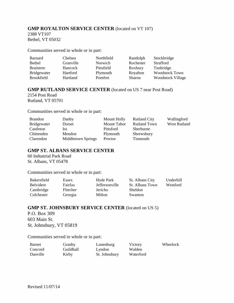
GMP ROYALTON SERVICE CENTER (located on VT 107) 2388 VT107
Bethel, VT 05032
Communities served in whole or in part: Barnard
Bethel
Braintree
Bridgewater
Brookfield
Chelsea
Granville
Hancock
Hartford
Hartland
Northfield
Norwich
Pittsfield
Plymouth
Pomfret
Randolph
Rochester
Roxbury
Royalton
Sharon
Stockbridge
Strafford
Tunbridge
Woodstock Town
Woodstock Village
GMP RUTLAND SERVICE CENTER (located on US 7 near Post Road) 2154 Post Road
Rutland, VT 05701
Communities served in whole or in part: Brandon
Bridgewater
Castleton
Chittenden
Clarendon
Danby
Dorset
Ira
Mendon
Middletown Springs
Mount Holly
Mount Tabor
Pittsford
Plymouth
Proctor
Rutland City
Rutland Town
Sherburne
Shrewsbury
Tinmouth
Wallingford
West Rutland
GMP ST. ALBANS SERVICE CENTER 60 Industrial Park Road
St. Albans, VT 05478
Communities served in whole or in part: Bakersfield
Belvidere
Cambridge
Colchester
Essex
Fairfax
Fletcher
Georgia
Hyde Park
Jeffersonville
Jericho
Milton
St. Albans City
St. Albans Town
Sheldon
Swanton
Underhill
Westford
GMP ST. JOHNSBURY SERVICE CENTER (located on US 5)
P.O. Box 309
603 Main St.
St. Johnsbury, VT 05819
Communities served in whole or in part: Barnet
Concord
Danville
Granby
Guildhall
Kirby
Lunenburg
Lyndon
St. Johnsbury
Victory
Walden
Waterford
Wheelock

Revised 11/07/14
GMP SPRINGFIELD SERVICE CENTER 38 Precision Drive
Springfield, VT 05156
Communities served in whole or in part:
Andover
Athens
Baltimore
Cavendish
Chester
Grafton
Hartland
Jamaica
Landgrove
Londonderry
Ludlow
Peru
Plymouth
Reading
Rockingham
Springfield
Townshend
Weathersfield
West Windsor
Westminster
Weston
Windham
Windsor
Winhall
GMP SUNDERLAND SERVICE CENTER (located on South Road near US 7 Exit 3)
357 South Road
E. Arlington, VT 05252
Communities served in whole or in part:
Arlington
Bennington
Dorset
Glastenbury
Jamaica
Manchester
Peru
Pownal
Rupert
Sandgate
Shaftsbury
Stratton
Sunderland
Winhall
Woodford
GMP WELLS RIVER SERVICE CENTER 22 Main Street
P.O. Box 677
Wells River, VT 05081
Communities served in whole or in part:
Barnet
Danville
Corinth
Groton
McIndoes Falls
Newbury
Peacham
Ryegate
Topsham
Waterford
Wells River
GMP WESTMINSTER SERVICE CENTER 1308 Westminster Heights Rd.
Westminster, VT 05158
Communities served in whole or in part:
Bellows Falls
Brookline
Dummerston
Putney
Rockingham
Saxtons River
Springfield
Vernon
Westminster

Revised 11/07/14
GMP WHITE RIVER JUNCTION SERVICE CENTER 64 Olcott Drive
Wilder, VT
White River Jct., VT 05001
Communities served in whole or in part:
Hartford
Hartland
Norwich
Wilder
Quechee
Thetford
GMP WILMINGTON SERVICE CENTER Haystack Road
P.O. Box 398
Wilmington, VT 05363
Communities served in whole or in part:
Dover
Halifax
Marlboro
Readsboro
Searsburg
Stamford
Stratton
Whitingham
Wilmington
Northfield Electric Department (Adopted) 51 South Main Street
Northfield, VT 05663
(802)-485-5411
(802)-485-8426 (fax) Communities served in part:
Berlin
Moretown
Northfield
Town of Hardwick Electric Department (Adopted) North Main Street, Box 516
Hardwick, VT 05843
(802) 472-5201
Communities served in part:
Calais
Crafsbury
Eden
Elmore
Hardwick
Hyde Park
Glover
Greensboro
Wolcott
Woodbury

Revised 11/07/14
Town of Stowe Electric Department (Not Adopted) Main Street, Box 190
Stowe, VT 05672
(802)-253-7392
(802)-253-7215
Communities served in part:
Stowe
Waterbury
Vermont Electric Cooperative, Inc. (Adopted) 42 Wescom Rd.
Johnson, VT 05656
(802) 635-2331
(800) VEC-COOP
Communities served in whole or in part:
Albany
Alburg
Averill
Avery’s Gore
Barton
Bakersfield
Belvidere
Berkshire
Bolton
Bloomfield
Brighton
Browington
Brunswick
Cambridge
Canaan
Charleston
Coventry
Craftsbury
Derby
Eden
Enosburg
Essex
Fairfax
Fairfield
Ferdinand
Fletcher
Franklin
Georgia
Glover
Grand Isle
Greensboro
Highgate
Hinesburg
Holland
Huntington
Hyde Park
Irasburg
Isle La Motte
Jay
Jericho
Johnson
Lemington
Lewis
Lowell
Lyndon
Maidstone
Milton
Montgomery
Morgan
Morristown
Newark
Newport
Newport City
North Hero
Norton
Richford
Richmond
St. Albans
St. George
Sheffield
Sheldon
Shelburne
South Hero
Starksboro
Stowe
Swanton
Troy
Underhill
Vernon
Waterville
Westfield
Westford
Williston
Village of Hyde Park, Inc. (Not Adopted)
P.O. Box 400
Hyde Park, VT 05655
(802) 888-2310
Communities served in part:
Hyde Park
Johnson
Morristown
Revised 11/07/14
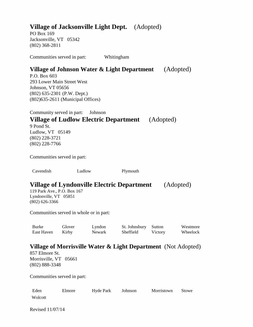
Village of Jacksonville Light Dept. (Adopted) PO Box 169
Jacksonville, VT 05342
(802) 368-2811
Communities served in part: Whitingham
Village of Johnson Water & Light Department (Adopted) P.O. Box 603
293 Lower Main Street West
Johnson, VT 05656
(802) 635-2301 (P.W. Dept.)
(802)635-2611 (Municipal Offices) Community served in part: Johnson
Village of Ludlow Electric Department (Adopted) 9 Pond St.
Ludlow, VT 05149
(802) 228-3721
(802) 228-7766 Communities served in part:
Cavendish
Ludlow
Plymouth
Village of Lyndonville Electric Department (Adopted) 119 Park Ave., P.O. Box 167
Lyndonville, VT 05851
(802) 626-3366
Communities served in whole or in part:
Burke
East Haven
Glover
Kirby
Lyndon
Newark
St. Johnsbury
Sheffield
Sutton
Victory
Westmore
Wheelock
Village of Morrisville Water & Light Department (Not Adopted) 857 Elmore St.
Morrisville, VT 05661
(802) 888-3348
Communities served in part:
Eden
Elmore
Hyde Park
Johnson
Morristown
Stowe
Wolcott

Revised 11/07/14
Village of Orleans Electric Department (Adopted) One Memorial Square
Orleans, VT 05860
(802)-754-8584
Communities served in part:
Barton
Browington
Coventry
Irasburg
Village of Swanton Electric Light Department (Adopted) P.O. Box 279
Swanton, VT 05488-0279
(802) 868-3397
Communities served in part:
Highgate
Swanton
Washington Electric Cooperative, Inc. (Adopted) Box 8, Route 14
East Montpelier, VT 05651
(802) 223-5245
Communities served in whole or in part:
Barnet
Barre
Berlin
Bradford
Brookfield
Cabot
Calais
Chelsea
Corinth
Danville
Duxbury
East Montpelier
Fayston
Greensboro
Groton
Hardwick
Marshfield
Middlesex
Moretown
Newbury
Northfield
Orange
Peacham
Plainfield
Randolph
Roxbury
Ryegate
Stannard
Topsham
Tunbridge
Vershire
Waitsfield
Walden
Washington
West Fairlee
Wheelock Williamstown
Woodbury
Worcester

Revised 11/07/14
TABLE OF CONTENTS
I. GENERAL INFORMATION
101. Requirements and Compliance with Electrical Code
102. Revision of Requirements
103. Departments of the Utility
104. Rate Assistance
105. Diversion of Electricity
106. Adequate Wiring
107. Special Cases
108. Written Confirmation
109. Customer Premises
110. Customer Responsibility
111. Access to the Premises
112. Unauthorized Attachment to Poles
113. Construction in the Proximity to Conductors
114. Continuity of Service
115. Voltage Sensitive Equipment
116. Losses, Damages or Injury
117. Life Support Systems
118. Digsafe
119. Unauthorized Work on Electric Utility Facilities
120. Modification of Service Equipment after Energization
II. GENERAL REQUIREMENTS FOR SERVICE
201. Planning for Service
202. Availability of Service
203. New Service
204. Relocation or Alteration of Existing Service
205. Load Changes
206. Temporary Service
207. Customer Service Costs
208. Energizing Permits
209. Limiting Service Fault Currents
210. Re-energization of Service
III. STANDARD SERVICE CHARACTERISTICS
301. Low Voltage Service
302. 120/240 Volt, Three Wire, Single Phase
303. 120/208 Volt, Three Wire, Single Phase
304. 120/208 and 277/480 Volt, Three Phase, Four Wire, Wye
305. 120/240 Volt, Three Phase, Four Wire, Delta Connected
306. High Voltage Service
Revised 11/07/14
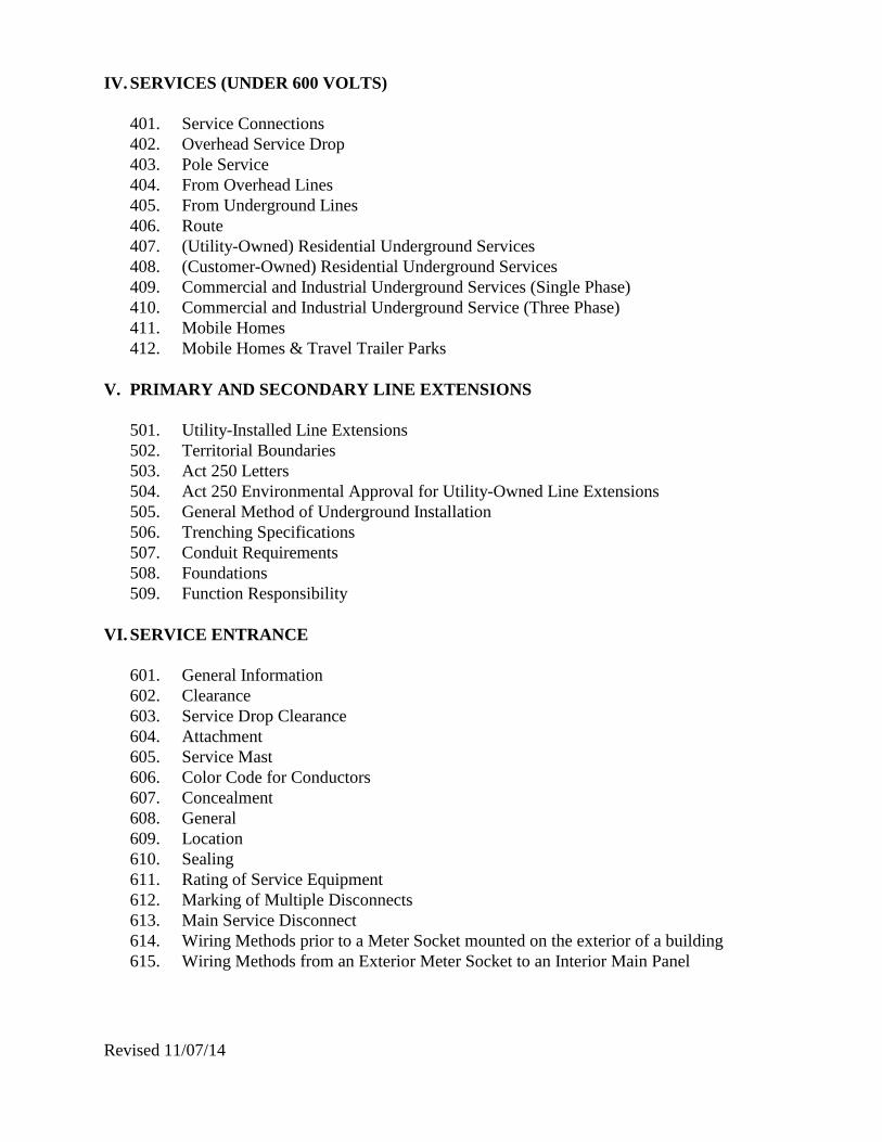
IV. SERVICES (UNDER 600 VOLTS)
401. Service Connections
402. Overhead Service Drop
403. Pole Service
404. From Overhead Lines
405. From Underground Lines
406. Route
407. (Utility-Owned) Residential Underground Services
408. (Customer-Owned) Residential Underground Services
409. Commercial and Industrial Underground Services (Single Phase)
410. Commercial and Industrial Underground Service (Three Phase)
411. Mobile Homes
412. Mobile Homes & Travel Trailer Parks
V. PRIMARY AND SECONDARY LINE EXTENSIONS
501. Utility-Installed Line Extensions
502. Territorial Boundaries
503. Act 250 Letters
504. Act 250 Environmental Approval for Utility-Owned Line Extensions
505. General Method of Underground Installation
506. Trenching Specifications
507. Conduit Requirements
508. Foundations
509. Function Responsibility
VI. SERVICE ENTRANCE
601. General Information
602. Clearance
603. Service Drop Clearance
604. Attachment
605. Service Mast
606. Color Code for Conductors
607. Concealment
608. General
609. Location
610. Sealing
611. Rating of Service Equipment
612. Marking of Multiple Disconnects
613. Main Service Disconnect
614. Wiring Methods prior to a Meter Socket mounted on the exterior of a building
615. Wiring Methods from an Exterior Meter Socket to an Interior Main Panel

Revised 11/07/14
VII. METERING
701. General Information
702. Meter Locations - Outdoor
703. Meter Locations - Indoor
704. Meter Height and Clearance
705. Standard Meter Installations
706. Moving or Removing Metering Equipment
707. Grounding of Meter Sockets and Current Transformer Cabinets
708. Joint Metering
709. Sub Metering
710. Metering Equipment Owned and Installed by the Customer
711. Installation of Sockets
712. Meter Socket Cover Plates
713. Meter Socket Connections
714. Identification of Meter Sockets and Customer Disconnecting Means
715. Multiple Meter Installations
716. Transformer-Rated Metering
717. Use of Instrument Transformer Cabinets
718. Metal-Clad Switchgear Installations
719. Sealing of Meters and Related Equipment
720. See Meter Socket Specifications (see drawing 601)
721. Meter Socket Concealment
VIII. CUSTOMER EQUIPMENT
801. General
802. Motors
803. Auxiliary or Emergency Systems
804. Standby Service
805. Customer Generation Operating in Parallel with the Utility System
806. Communications
807. Energy Management Systems
808. Power Factor Correction
809. Alternating Current Arc Welders
810. Intermittently Operated Equipment
811. Heating Equipment
812. Luminous Tube Signs and Lamps
813. Harmonic Distortion
IX. GROUNDING
901. General Information
902. Grounding Electrode System
903. Ground Rods
904. Ground Rod Installation
905. Grounding Conductor Size
Revised 11/07/14
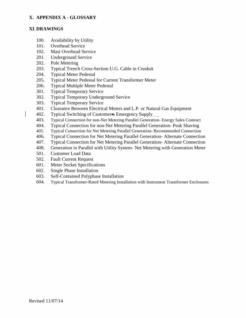
X. APPENDIX A - GLOSSARY
XI. DRAWINGS
100. Availability by Utility
101. Overhead Service
102. Mast Overhead Service
201. Underground Service
202. Pole Metering
203. Typical Trench Cross-Section U.G. Cable in Conduit
204. Typical Meter Pedestal
205. Typical Meter Pedestal for Current Transformer Meter
206. Typical Multiple Meter Pedestal
301. Typical Temporary Service
302. Typical Temporary Underground Service
303. Typical Temporary Service
401. Clearance Between Electrical Meters and L.P. or Natural Gas Equipment
402. Typical Switching of Customer=s Emergency Supply
403. Typical Connection for non-Net Metering Parallel Generation- Energy Sales Contract
404. Typical Connection for non-Net Metering Parallel Generation- Peak Shaving 405. Typical Connection for Net Metering Parallel Generation- Recommended Connection
406. Typical Connection for Net Metering Parallel Generation- Alternate Connection
407. Typical Connection for Net Metering Parallel Generation- Alternate Connection
408. Generation in Parallel with Utility System- Net Metering with Generation Meter
501. Customer Load Data
502. Fault Current Request
601. Meter Socket Specifications
602. Single Phase Installation
603. Self-Contained Polyphase Installation
604. Typical Transformer-Rated Metering Installation with Instrument Transformer Enclosures

Revised 11/07/14
I. GENERAL INFORMATION
101. Requirements and Compliance with Electrical Code
A. The requirements stated herein are not intended to supersede or conflict with the pertinent
standards and regulations of the National Board of Fire Underwriters or with any state or municipal rule
now in effect or which may later be enacted. The latest revision of the National Electric Code of the
National Board of Fire Underwriters is a minimum requirement. Some requirements in addition to those
in the latest edition of the National Electric Code are contained herein because the Utility deems them
advisable for the safety of customers and employees. SERVICE CONNECTION WILL NOT BE
MADE UNTIL APPROVAL IS RECEIVED FROM THE APPROPRIATE STATE OR LOCAL
INSPECTION AUTHORITY WHEN REQUIRED. The Utility has no obligation to determine
whether or not the customer's wiring and installations are proper and safe or comply with the National
Electrical Code, National Electric Safety Code, or other codes or regulations in effect at the customer's
location. However, if it comes to the attention of the Utility that the customer's wiring and electrical
installations are not proper and safe, or do not comply with such codes, the Utility has the right to refuse
or discontinue service.
B. The definitions established by the latest edition of the NEC shall be applicable to these electric
service information requirements.
102. Revision of Requirements
The contents of this book are effective as dated and supersede all similar requirements previously
issued. Revisions of this information shall be made as necessary and the Utility reserves the right to
make such revisions. The Utility cannot guarantee to give notice of revisions to persons who may have
received this book. IT SHALL BE THE RESPONSIBILITY OF THE CUSTOMER TO VERIFY
WITH THE LOCAL UTILITY THAT THEY HAVE THE LATEST VERSION OF THIS BOOK
PRIOR TO CONSTRUCTION. All services shall be required to comply with the most recent set of
requirements.
103. Departments of The Utility
The Utility has specialized departments and individuals to assist with customer electrical
requirements. Check with your local Utility for more information.

Revised 11/07/14
104. Rate Assistance
Utilities are prepared to assist in the selection of the available rate, or rates, best suited to the
customer's use of electricity at the time of installation. It is strongly urged that customers, contractors,
architects, electricians, consultants, and design engineers take advantage of this assistance prior to
installation of the end users' electric service. Utilizing the Utility’s advice may avoid delays and result in
greater satisfaction and more efficient use of electric service.
105. Diversion of Electricity
A. Diversion of electrical energy is any method, or device, used by any agent to unlawfully and/or
intentionally prevent, or interfere with, an electric meter from duly registering the proper quantity of
electricity supplied by the Utility. It is also the unlawful, or intentional, taking of any electrical current
from any wire of the Utility without the consent of the Utility. The diversion of electrical energy by any
method or device is a serious act against the Utility and its customers, as it results in higher operating
expenses for the Utility and increased electric rates to its customers. Diversion could create potential
hazardous conditions. Vermont law (13 VSA §§ 3782, 3784 & 2528) provides penalties for diversion
and tampering with electric lines and energy metering.
B. Where there is proof of meter tampering or theft of electrical energy, such person, or persons,
responsible shall be liable for the energy so diverted and shall be subject to civil prosecution.
106. Adequate Wiring
The latest edition of the NEC outlines in detail the recognized minimum safe practices which should
be followed when installing electric wiring and equipment. Compliance with the Code only assures that
the installation will conform with recognized safe practices. The customer's consultant should aid the
customer in obtaining a wiring installation that is not only safe, but is adequate to his present and future
needs.
107. Special Cases
Careful consideration will be given to special or unusual conditions. The Utility reserves the right to
permit departure from these requirements when, in its judgment, conditions warrant. Such departure
will not be considered as establishing a precedent.
108. Written Confirmation
Information furnished by the Utility will be put in writing upon request. The Utility assumes no
responsibility for misunderstandings resulting from verbal communications.
Revised 11/07/14
109. Customer Premises
The Utility shall not be liable for damages to the person, property of the customer, or any other
persons arising from the use of electricity or the presence of the Utility's equipment on the customer's
premises. All property owned by the Utility and located on the customer's premises shall be deemed to
be personal property and title thereto shall remain in the Utility, and the Utility shall have the right at the
termination of service to remove all of its property whether affixed to the realty or not.
110. Customer Responsibility
The customer shall be responsible for safekeeping of property of the Utility on their premises and, in
the event of damage, shall pay to the Utility any cost of inspection and repairs. The customer shall
protect the equipment of the Utility on their premises and shall not permit any person, except an
authorized representative of the Utility, to break any seals upon or do any work on any meter or other
apparatus of the Utility located on the customer's premises.
111. Access to the Premises
The Utility shall have the right of access to a customer's premise, and to all property furnished by the
Utility installed therein, at all reasonable times during which services are furnished to the customer and
on or after its termination for the purpose of reading meters, inspection and repair of devices used in
connection with its services, removing its property, or for any other proper purpose. Identification will
be shown upon request.
112. Unauthorized Attachment to Poles
The Utility forbids the unauthorized attachment of any flags, banners, signs, clothes lines, antennas,
basketball hoops, etc. to any of its poles. It forbids the use of its poles for any placards, political posters,
or any advertising matter. The Utility will remove any such unauthorized attachment without notice and
may prosecute such trespassing.
113. Construction in the Proximity to Conductors
A. Construction in proximity to any electrical conductor shall not be started until the Utility has
been contacted and it has been determined that such construction will not violate the requirements of the
applicable electrical codes, national electrical safety codes, laws of the state, and/or local municipal
authorities.
B. Swimming pools shall not be constructed in proximity to any electrical conductor per the
applicable electrical codes.
C. The cost of relocation of electrical facilities to comply with A and B above shall be borne by the
customer.

Revised 11/07/14
114. Continuity of Service
The Utility makes every effort to maintain its system at the highest possible standards, but assumes
no liability as a result of any failure of its service or equipment. The Utility reserves the right to
interrupt service to a customer without notice when repairs or changes make such a procedure necessary
or appropriate, and also to restore service without notice when such work is completed. Any equipment
which might endanger life or damage property under such condition or under conditions of low voltage,
two phase, or single phase operation, should be provided with suitable automatic protection by the
customer.
Should the supply of service be curtailed, changed, interrupted, or become impaired because of
accident, strike, legal process, federal, state, or municipal interference, or any cause whatsoever beyond
the Utility's control and except as caused by willful default or neglect on its part, the Utility shall not be
liable for damages, direct or consequential, resulting from such interruption, impairment, curtailment, or
change.
115. Voltage Sensitive Equipment
Customers owning, or planning to purchase computers, reproduction, X-ray, data processing
equipment, or similar devices should be aware that this type of equipment can be extremely sensitive to
power system transients or loss of voltage. Customers should consult the manufacturer of their
equipment for suitable devices to protect against these conditions. The Utility cannot assume
responsibility for voltage variations which may be caused by protective equipment operation, switching,
lightning surges, or by other conditions normal or emergency in nature.
116. Losses, Damages or Injury
The Utility shall not be responsible for any losses, damages, or injury resulting from:
* Any cause resulting from the actions of the customer’s electrician or contractor.
* The customer's wiring or appliances if faulty, improperly grounded/connected, used or
inappropriately sized for the customer's service.
* The customer's intentional or unintentional overloading of the service provided.
* The customer's non-compliance with the Guidelines.
* Tampering with or alteration of Utility’s meters, lines, transformers or other equipment whether
or not located on the customer’s premises.
* Any other cause not resulting from the sole negligence of the Utility.
117. Life Support Systems
The Utility recognizes some customers may rely on life support equipment connected to electric
service supplied by the Utility. The Utility strongly encourages these customers to report this condition
to the Utility. The Utility shall not be responsible for any life- or health-threatening incidents these
customers may incur due to variation of electric service. Therefore, the Utility urges these customers to
have adequate back-up.

Revised 11/07/14
118. Underground Utility Damage Prevention System
A. DigSafe® is the PSB designated One Call System for Vermont. The DigSafe® office should be
contacted at least 48 hours, not including weekends or legal holidays, before digging or excavating on
public or private property. The Underground Utility Damage Prevention System, 30 VSA §7001-7008
requires everyone to contact the DigSafe® program at 811 or 1-888-Dig-Safe (1-888-344-7233).
Dig Safe Systems, Inc.
11 Upton Drive
Wilmington, MA 01887
DigSafe® is a non-profit One-Call notification service servicing Vermont, New Hampshire, Maine,
Massachusetts, and Rhode Island. A call to DigSafe® notifies the appropriate Utility to mark their
underground lines.
The Underground Utility Damage Prevention System statute and PSB rules do not apply to most
Vermont Municipal Water and Sewer systems. You must contact them directly to request marking.
B. Hours: DigSafe® operates during regular business hours, excluding holidays and weekends, and
is available for emergency calls 24 hours a day, 7 days a week.
C. Excavation Activities Defined: The Underground Utility Damage Prevention System defines
excavation activities as “activities involving the removal of earth, rock or other materials in the ground,
disturbing the subsurface of the earth, or the demolition of any structure, by the discharge of explosives
or the use of powered or mechanized equipment, including but not limited to digging, trenching,
blasting, boring, drilling, hammering, post driving, wrecking, razing or tunneling, within 100 feet of an
underground Utility easement (which includes private property), or the area of a public right-of-way in
which an underground Utility facility is located. Excavation activities shall not include the tilling of the
soil for agricultural purposes or activities relating to routine public highway maintenance.”
D. Responsibility: The excavator is responsible for knowing and understanding the Underground
Utility Damage Prevention System. Any person or Utility who violates this law is liable for damages
and subject to fines and penalties.
E. Premarking: The proposed excavation areas shall be premarked, prior to calling DigSafe®.
Premark with white paint, stakes, or other suitable white markings to identify the general scope of the
excavation. Premarking is not required if the actual excavation will be continuous and will exceed 500
feet in length; or, if the boundaries of the excavation can be described in a way that precisely identifies
the boundaries of the excavation, to the owner of the underground Utility facility.
F. Horizontal or Directional Boring: When excavation activities involve horizontal or directional
boring, the excavator shall expose underground facilities to verify their location and depth, in a safe
manner, at each location where the work crosses a facility and at reasonable intervals when paralleling
an underground facility. The exposure shall occur after the DigSafe® procedure, and prior to boring.

Revised 11/07/14
119. Unauthorized Work on Electric Utility Facilities.
Customers and their Contractors are prohibited from working on, or in, Electric Utility Facilities.
Specifically, they shall not install, remove, maintain, or adjust equipment on, or in, Utility owned poles,
terminating cabinets, padmounted transformers, secondary pedestals, secondary handholes, manholes or
switchgear. If the Utility becomes aware that individuals are violating this prohibition, the Utility will
write the offender a letter asking them to Cease and Desist. Copies will go to the Electricians Licensing
Board, State Utility Regulators, and OSHA. Failure to comply with this requirement will result in the
initiation of procedures with state regulators and safety officials. The following are exceptions:
- Installation of service riser equipment, which is installed on a pole, within 8 feet of the grade, by
persons standing on the ground.
- Installation and removal of seasonal decorations and banners, on a pole, at a height selected by
Electric Utility Personnel. Such attachments require specific advance approval.
- Installation of conduits, and cables, into device foundations prior to initial energization.
- Installation of conduits, and cables, into device foundation subsequent to initial energization, but,
under the direct supervision of Electric Utility Personnel.
- Other work deemed appropriate by the responsible Electric Utility Personnel.
This prohibition applies to Customers and their Contractors making or removing connections between
the Utility Owned Overhead Service Drop and the Customer Owned Service Entrance Cable, unless
specific approval is made in advance.
This prohibition is not directed toward personnel or contractors employed by Utility Joint Users. And, it
is not directed toward customers, or their contractors, working on customer owned facilities, unless
those facilities are mounted upon, or within, Utility owned facilities.
120. Modification to Service Equipment after Energization.
Customers and their Contractors are prohibited from modifying service equipment, without the
notification and consent of the Utility, and, when required, the appropriate State or Local Inspection
Authority. Examples of modifications that require prior notification and consent are:
- Replacing a Service Entrance cable fed from a Utility owned overhead service.
- Connecting a new, or relocated, building, trailer or structure, to a pre-existing service. This does
not apply to connections made from the main panel in the pre-existing building.
- Changes in the buildings or structures, which reduce clearances to, or increase access to, a Utility
owned overhead or underground service.
- Changes in the buildings or structures, which reduce clearances to, or reduce access to, a meter
socket.
- Replacing a customer owned underground service fed from a pole meter or pedestal meter.
- Replacing, or adding, a main panel for the purpose of increasing capacity.
- Other actions that may create safety concerns, NEC violations, equipment overloads, or be
contradictory to these Service Requirements or Utility Tariffs.

Revised 11/07/14
II. GENERAL REQUIREMENTS FOR SERVICE 201. Planning for Service
A. Application for new service, or changes to existing service, should be made with the Utility nearest the job location. Consult list of Utilities for localized assistance. APPLICATION SHOULD BE MADE AS FAR IN ADVANCE AS POSSIBLE OF THE DATE ELECTRIC SERVICE IS REQUIRED. The customer, or their representative, should consult the Utility regarding the character of service available before plans are completed, equipment purchased, or construction commenced on facilities to be connected to the Utility's distribution system. Information the customer or their representative furnishes the Utility with regard to the proposed electrical installation should be technically detailed, in writing, and sent to the local Utility.
All equipment using electrical energy should comply with Energy-Efficiency Guidelines. Check with your local Utility for compliance.
B. A CUSTOMER LOAD DATA SHEET (DRAWING #501), INDICATING THE SERVICE REQUIREMENTS FOR THE PROJECT, AND A SITE PLAN SHALL BE SUBMITTED TO THE LOCAL UTILITY FOR ALL COMMERCIAL AND INDUSTRIAL SERVICES AT THE EARLIEST POSSIBLE TIME. Data should include the size of the main disconnect, phase(s), voltages, connected KW load, phase conductor and neutral/ground, peak and coincidental demand. This information is vital for the design of the Utility’s distribution facilities to service a customer's requirements. No equipment shall be placed on order without this information. Many construction materials and transformers require a lead time of six months or more to be obtained.
The Utility may require the site plan to be on a diskette. Check with the local Utility. NOTE: The site plan shall be on a disk with a cad file having an extension of “.DWG”, or “.DGN”. If a cad file is not available files having extensions of “.IGES” or “.DXF” are necessary. Mylars will still be acceptable when the previously mentioned medium is not available.
C. Individual residential customers shall not be required to furnish a diskette or mylar site plan but should consult with the local Utility during the planning stages to ensure electrical service will be available when required. A site plan, or sketch, would be helpful in determining the location of the distribution lines.
Revised 11/07/14
202. Availability of Service
A. Underground Service
The Utility shall be consulted before work begins to determine the feasibility of underground service. Municipal requirements, soil, and terrain conditions shall, in the opinion of the Utility, be compatible with those on which the policy is based. Unsuitable terrain includes, but is not limited to, ledge, excessively wet areas, leach fields, and waste disposal areas. UD in some areas may result in excessive costs for the customer due to special engineering and installation costs.
B. Three-phase service
THREE-PHASE SERVICE IS NOT READILY AVAILABLE IN ALL LOCATIONS. The Utility shall be consulted before three-phase installations are designed and constructed. Failure to do so may result in a substantial expense, or delay, which could otherwise have been avoided. 203. New Service
A. CUSTOMERS INSTALLING NEW ENTRANCES SHALL CONSULT WITH THE UTILITY FOR THE LOCATION OF SERVICE ENTRANCES AND METERS BEFORE WIRING IS STARTED. The point of attachment to the service drop and the location of the meter shall be determined solely by the Utility. If a state or local wiring permit is required, the customer should obtain approval of these Utility-chosen locations by the inspector having jurisdiction before wiring begins. Approval by the Utility is required, but does not imply approval by state or local inspectors.
B. All single-phase service shall be three-wire, and all single-phase service equipment shall be provided with two-pole overload protection and a solidly grounded neutral as required by the latest edition of the NEC and/or the authority having jurisdiction. In cases where an existing two-wire service entrance is being changed to a three-wire service the existing load shall be balanced. It is the customer's responsibility to accomplish the balancing. Exceptions shall be made for individual equipment which only requires 120 volt service (i.e. cable television amplifier). The grounded conductor shall be identified in accordance with the requirements of the latest edition of the NEC and/or the authority having jurisdiction.
C. Normally, only one service will be installed for a customer at a given location. Two or more services may be installed at the option of the Utility, if approved by appropriate governing or inspecting authority, to supply suitable capacity, special loads, or to meet unusual conditions. When electricity is metered by more than one meter, the cost of service delivered through each meter will be computed separately. A location requiring both three-phase and single-phase service shall balance the single-phase load across all three phases and receive only four-wire wye service where practical. The Utility reserves the right to determine the type of service which will be supplied.

Revised 11/07/14
204. Relocation or Alteration of Existing Service
A. Whenever changes are made in existing service installations involving relocation, replacement, or additions, the entire service installation shall, to the extent practical, be subject to, and rebuilt to, present standards. Customers are urged to contact the Utility before putting out to bid any changes that may be made and for any special requirements the Utility may have. Discussions as to the actual changes required shall be determined by consultation with the customer, the Utility, and the local electrical inspector on an individual basis. In the event that the Utility shall be required to place any portion of its existing overhead distribution system underground, or is required to change the location of any poles in its distribution system, a new point of delivery will, if necessary, be designated by the Utility. The customer may be required to make any necessary changes in their wiring system at their own expense.
B. If, for any reason, a customer makes any change in their wiring involving a change of meter or service location, the addition of one or more meters, or major changes in repair to existing service entrance wiring, the customer shall follow the provisions of these requirements. Customers are encouraged to check with the Utility for any charges to be paid by the customer relating to the foregoing work.
C. If a customer desires a change of service, and the meters are to be left in an indoor location, the change must first be approved by the Utility. 205. Load Changes
The customer shall give proper notice to the Utility of any substantial increase or decrease proposed in their connected load, or of any proposed change in characteristics, purpose of use, or location of load. Failure on the part of the customer to give notice as provided above shall render them liable for any damages to meters, transformers, wires, and associated apparatus of the Utility resulting from the use of increased or changed load. 206. Temporary Service
A. A "temporary service" is generally supplied by the Utility for a period not to exceed six months. The Utility reserves the right to remove the temporary service after the six month period. Check with the local Utility on availability.
B. The customer shall pay in advance for a temporary service an amount equivalent to the cost of installing, connecting, and removing the Utility's service facilities connected to the customer's temporary service at the filed rate.
C. The standard temporary service is generally limited to 200 ampere, single-phase, three-wire 120/240 volts. Other voltages, phasing, and capacity characteristics may be available for installation at an additional cost to the customer.
D. The maximum distance for a temporary overhead service drop is 100 feet. The customer shall supply a suitable point of attachment as shown in attached Drawings 301 and 303. A tree may not be used for this purpose.
GMP Only- A tree, that has been topped and limbed-out, may serve as a support for a temporary service, provided that it is of sufficient height and strength.

Revised 11/07/14
E. In areas where the primary voltage distribution system is underground, temporary service for construction purposes will be installed under the provisions of Section 203 and Drawing 302, providing further that:
1. The primary conductors and transformers to serve the customer's permanent installation have already been installed, connected, and energized.
2. The customer has provided a suitable support adjacent to the transformer and installed thereon
the appropriate meter socket, protection device, grounds, etc. The customer and/or contractor must contact the Utility for details on the temporary connections between the transformer and the meter.
F. All wiring shall comply with the latest edition of the NEC.
207. Customer Service Costs
A. Information relating to the portion of the service construction costs to be paid by the customer shall be supplied by the Utility when requested by the customer. The customer requesting service shall be charged in accordance with established tariffs. A copy of the price list is available upon request from your local Utility. Commercial and industrial customers and developers shall submit to the Utility a site plan and Customer Load Data Sheet (refer to Drawing 501). The Utility shall design its electrical distribution facilities to serve a customer's requirements and provide information for cost quotation. Prices quoted for all primary line extensions shall be in writing by a Utility representative. Prices are subject to change; check with your local Utility for information about the length of time that pricing remains valid.
B. Income Tax Assessment - The Tax Reform Act of 1986 requires that the Utility pay both Federal and State income tax on contributions in-aid-of construction. This tax assessment shall be levied on all Investor-Owned Utility (IOU)-built extensions and on customer-installed extensions when the Utility takes over ownership and maintenance.
208. Energizing Permits
The Utility is not allowed to energize a service (commercial, including rental or multiple-unit) until an approved energizing permit has been issued by the authority (State of Vermont and/or municipality) requiring such inspection. It is the responsibility of the customer to follow whatever procedure is required by the State of Vermont or municipal authority to assure that the Utility receives an energizing permit prior to the time that electrical service is required. No portion of the service equipment, including the service drop or underground service, may be energized prior to receipt of the permit.
Under current law, State Electrical Inspectors only have jurisdiction in public buildings. They do not
have jurisdiction in single-unit buildings occupied by the owner as their personal residence. All rental properties are considered public buildings regardless of the number of units.
For customer owned equipment, any of this manual’s requirements, that are in excess of code specified
minimums, are recommended not required.

Revised 11/07/14
209. Limiting Service Fault Current
Typical minimum rating low voltage disconnect/breakers are rated for a maximum interrupting capacity of 10,000 amps. The chart below shows combinations of transformer impedance and cable lengths, that would result in fault currents less than, or equal to, 10,000 amps. Because the initial design, and future changes, are possible, both on the Utility side, and on the customer side, the Utility, Customer, and the Customer’s Contractor must work together to ensure an appropriate breaker rating. The most frequent instances where this is an issue are: a small customer is fed from a large transformer; a pole meter/disconnect, or pedestal meter/disconnect, is close to the transformer; or, a small temporary service meter/disconnect is fed by a large transformer. Alternatively, a breaker with a higher interrupting rating can be used. Transformer Imp. Phases Fault Amps Cable Length (Ft.) Size (kva) W/O Cable 1/0 Al 4/0 Al 350 Mcm Al 15-120/240 1.5% Single 7 ka 0 ft 0 ft 0 ft 25-120/240 1.5% Single 12 ka 10 15 20 37.5-120/240 1.5% Single 18 ka 20 35* 45* 50-120/240 1.5% Single 24 ka 25 45* 65* 75-120/240 1.5% Single 36 ka 45* 80* 110* 100-120/240 1.5% Single 48 ka 50* 90* 130* 167-120/240 1.5% Single 80 ka 55* 100* 150* 75-208Y/120 1.5% Three 14 ka 30* 45* 65* 112-208Y/120 1.5% Three 21 ka 45* 75* 110* 150-208Y/120 1.5% Three 28 ka 50* 90* 130* 225-208Y/120 1.5% Three 42 ka 55* 100* 150* 300-208Y/120 2.5% Three 34 ka 50* 90* 135* 500-208Y/120 2.5% Three 56 ka 55* 100* 155*
*For Utilities that require a meter/disconnect, Pole Metering is not available, unless a disconnect with a higher interrupting rating is used. 210. Re-energization of Service
In circumstances where a service is to be re-energized after a customer’s property is damaged, such as a fire or flood, or, that the property has been without service for an extended period of time, as determined by the Utility, the Utility may have requirements to be met before the service is re-energized. Contact your Utility for any such requirements.
An energizing permit from a State Electrical Inspector is required only when a new electrical service
is installed in a public building and is not required for re-energizing existing electrical services, in a public building or a private residence, after a fire, flood, or extended period without service. In the event of a region wide disaster such as a flood, State Electrical Inspectors may be directed by the Vermont Department of Public Safety to act in an advisory capacity evaluating any affected structure, but there is no statutory requirement that they do so.
If there is any question whether or not a repair, in a public building, is extensive enough to be considered a new service, the State Electrical Inspector for the area where the structure is located should be contacted for clarification.

Revised 11/07/14
III. STANDARD SERVICE CHARACTERISTICS 301. Low-Voltage Service
Alternating current, 60 Hertz service is supplied throughout the territory served by your Utility. Characteristics of the service available in any locality should be obtained from your Utility before ordering any new, additional, or replacement equipment.
Low voltage service for secondary rate customers will be supplied from the nearest suitable distribution line of the Utility at one of the following standard service voltages:
Single-Phase 3-Wire 120/240 Volts
Three-phase Wye, Delta or voltage variations may not be available in all locations. Check with your
local Utility.
Three-Phase (Overhead) Three-Phase (Underground) 4-Wire Wye 120/208 Volts 4-Wire Wye 120/208 Volts 4-Wire Wye 277/480 Volts 4-Wire Wye 277/480 Volts 3-Wire Delta 240 Volts 3-Wire Delta 480 Volts 4-Wire Delta 120/240 Volts
Voltage
Availability by Utility
GM VE WE LE HE
VJ
NE
4-Wire Wye 120/208 Volts A A A A A A A 4-Wire Wye 277/480 Volts A A B A A A A 3-Wire Delta 240 Volts F E E E E E E 3-Wire Delta 480 Volts F E E E E E E 4-Wire Delta 120/240 Volts C E E E E E E 4-Wire Open-Delta 120/240 Volts D D E E E D E
A- Available in all three phase locations, either pole-mounted or pad-mounted. B- Available in all three phase locations as pole-mounted; not available as pad-mounted. C- Available in areas not planned for future 34.5 kv distribution, as pole-mounted; not available as pad-mounted. D- Available in all two phase locations, for limited loads, as pole-mounted; not available as pad-mounted. E- Not available for new installations. F- Available only in areas that have delta primary configuration.
The voltages are nominal and subject to reasonable variations in accordance with regulatory commission standards.
Check with your local Utility. Utilities have stocking limitations on transformer sizes. This may result in a particular voltage not being available for a range of transformer size or range of customer load.

Revised 11/07/14
302. 120/240 Volt, Three Wire, Single Phase
Generally available for residential and small commercial and industrial customers for general lighting, heating, cooking, and small power loads with individual motors not over 5 h.p.
Where the total load exceeds 50 KVA, your local Utility may, at its option, require the customer to arrange his wiring for three phase service. 303. 120/208 Volt, Three Wire, Single Phase
Available only where the low voltage distribution system is three phase, four wire, 120/208 volts, Wye connected, for services of similar uses and size as covered in Section 302. 304. 120/208 and 277/480 Volt, Three Phase, Four Wire, Wye
These services are preferred voltages for commercial and industrial service and can be supplied where three phase distribution is available. 305. 120/240 Volt, Three Phase, Four Wire, DELTA Connected
For combined single phase, 120/240 volt and three phase, 240 volt service, or where only two phase distribution is existing. This service will not be available from 34.5 KV distribution, and may not be available from your local Utility. 306. High-Voltage Service
Primary voltages are available. Check with the local Utility for more information.
Service Type
Availability by Utility
GM VE WE LE HE
VJ
NE
Three-Phase Primary Distribution Y Y N Y Y Y Y Three-Phase Subtransmission Y Y N N N N N Single-Phase Primary Overhead Distribution Y* Y N Y N Y Y Single-Phase Primary URD Distribution Y* Y N Y N Y Y Y* -Residential customers may only own overhead or underground primary installations with both utility and PSB approval.

Revised 11/07/14
IV. SERVICES (UNDER 600 VOLTS)
401. Service Connections
A. All final connections, permanent or temporary, between the customer's wiring and the Utility's distribution lines or equipment shall be made by the Utility. The Utility shall not permit, tolerate, or authorize connections by anyone other than the Utility’s personnel without prior approval of the Utility.
B. The Utility shall be the final authority in determining the size and characteristics of the wire used for interconnection between the Utility and the customer. 402. Overhead Service Drop
A. The Utility shall not allow a connection between its service drop and the customer's service entrance conductors unless a sufficient length of service entrance conductor (2 feet or more) is left for this purpose.
B. Large-capacity commercial and industrial overhead services require that the transformer pole, terminal pole, or structure in most cases be situated no further than 100 feet from the weatherhead(s) on the facility being served because of the weight of the service conductors. A mid-span support pole may be required even at these distances. The customer shall provide a point of attachment on the building or facility, such as an eye bolt, capable of supporting the service conductors. The hardware shall be provided by the local Utility and the customer shall install it. The maximum capacity of transformers that the local Utility will install on a pole is limited due to the weight of transformers, check with your local Utility for the maximum size. A facility requiring capacities in excess of these, or having limitations due to the number or size of the secondary cables shall be served from a pad-mounted transformer or special substation. Associated costs shall be borne by the customer.
C. The service drop shall have the clearances above ground, above structures, and horizontal clearances as specified in the National Electrical Safety Code. For customer-owned services NEC will apply. 403. Pole Service
Many Utilities do not allow metering on poles. Contact your local Utility regarding availability of this type of service and installation practices. See Drawing 202. 404. From Overhead Lines
When requested by the customer and accepted by the local Utility, or where conditions require it, an underground service may be installed from overhead supply lines. See Drawings 201 and 202.

Revised 11/07/14
405. From Underground Lines
In those areas served by underground distribution, all new services shall also be installed underground. 406. Route
The local Utility will determine the route of the Utility-owned underground service from the distribution system to the building. 407. (Utility-Owned) Residential Underground Services
A. All trenching and backfilling shall be provided by the customer, see Drawing 203 for Trenching Specifications.
B. Conduit is required for the Utility-owned underground service and shall be provided and installed by the customer, (refer to Section 513 for Conduit Requirements).
C. If the customer elects to install the service, including service cable and conduit, it shall be done in accordance with the requirements of this section and Drawings 201 and 202. A minimum of forty continuous feet (or unless otherwise agreed to) of service cable shall be provided at the base of the pole for connection to the Utility’s system. The local Utility may provide and install the stand-offs, conduit, condulator-weatherhead and other associated equipment on the pole, above the sweep after the customer has installed the conduit in the ground. The Utility’s field representative may provide and install, if practical, the first stand-off as a guide for the proper installation, by the customer, of the conduit adjacent to the pole.
D. If an underground service cable, (owned by the Utility), fails and is considered by the local Utility not to be repairable, the local Utility shall install the new underground. In some circumstances a temporary repair may be necessary prior to a permanent repair.

Revised 11/07/14
E. The following chart delineates the division of functions between the Customer and the Utility.
This chart also applies to Paragraph 408 (Customer-Owned) Residential Underground Service.
Single Phase Low Voltage URD Service
Availability by Utility
GM VE WE LE HE
VJ
NE
Res. URD Ownership before Meter D A B B B B B Res. URD Ownership after Meter C C C C C C C Stand-off Brackets Provided by U U C C U C U Riser Conduit Provided by C U C C C C C Weatherhead Normally Required Y1 Y N Y Y N Y Condulator Normally Required Y1 N Y N N Y N Weatherhead/Condulator Provided by C U C C C C U Expansion Joint Provided by C C C C C C C Riser Installation by U U U U U U U Trenching and Backfill by C C C C C C C Trench Conduit by C C C C C C C Trench/Conduit Inspection by U2 U C C C U U Warning Tape Installation by C C C C C C C Conduit Highly Recommended Y Y Y Y Y Y Y Conduit Required D Y Y N Y Y Y Cable Provided by C C C C C C C Cable Installed by C C C C C C C Padmount Secondary Connectors by U1 U1 U U1 U U1 U1 Pole Meter Required N N N N N N N Pole Meter Allowed U2 Y NA N U2 N U2 Disconnect Required at Pole Meter* Y Y NA NA N NA Y Pole Meter Socket Installation by C U NA NA C NA U Bldg. Meter Socket Installation by C C C C C C C
Y-Yes N-No Y1- Weatherhead required 350mcm Aluminum and smaller, and 4/0 Copper and smaller. Condulator required for larger conductors and for multiple cables in one conduit. A-Residential URD Services are normally Utility-Owned. B-Residential URD Services are normally Customer-Owned. C-Customer provided material/function. D- Residential URD services are either to be Utility-Owned or Customer-Owned at the Customer’s option. Utility-Owned services are limited to single runs of 1/0, 4/0 or 350mcm aluminum no longer than 400 ft. Length limitations by voltage-drop also apply. Utility Owned Services require conduit. Conduit is highly recommended for Customer Owned Services. NA- Not Applicable U-Utility provided material/function. U1-Padmount secondary connectors normally provided by Utility; however, the customer shall provide connectors for conductors larger than 350MCM. U2- Function may be available at Utility’s option. * See Paragraph 209. A meter/disconnect on a pole (or pedestal), other than on a mobile home service, shall not normally be considered to be the Main Service Disconnect. Four wire services are only required after the Main Service Disconnect.

Revised 11/07/14
408. (Customer-Owned) Residential Underground Service
A. Many Utilities do not allow customer-owned underground residential service. Check with your local Utility for details. The installation must conform to and meet the Utility=s specifications. The customer may, with the advance approval of the local Utility, install, own, and maintain his own secondary underground service from either the Utility's overhead distribution system or from the secondary terminals of the Utility's nearest underground system distribution transformer. All connections to the Utility=s distribution system will be made by Utility employees. The attachment of the customer's underground service facilities to the Utility=s pole will be performed by the Utility and the cost of such work will be borne by the customer, less a credit, if applicable, equivalent to the cost of an overhead service if normally furnished by the Utility in accordance with tariff provisions.
B. All trenching and backfilling shall be provided by the customer, (refer to Drawing 203 for Trenching Specifications).
C. Conduit may be required for the customer-owned underground service and shall be provided and installed by the customer. Check with local Utility to see if conduit is required, (refer to Section 513 for Conduit Requirements). For customer-owned underground service, a conduit installation is always highly recommended. Experience shows that the lack of the conduit results in a significantly higher failure rate, and more expensive repairs. However, the NEC does not require conduit, so, this document will not require conduit for customer-owned underground service.
D. With the customer-owned underground, the customer shall buy, install and maintain the undergound service. The meter location will be determined by your local Utility.
E. The Chart in paragraph 407E applies to Customer-Owned Residential Underground Services.
409. Commercial and Industrial Underground Services (Single-Phase)
A. All commercial or industrial underground services shall be installed, owned, and maintained by the customer.
B. The customer shall retain ownership and perform all future maintenance work. It is recommended that services be installed in electrical-grade conduit for the entire service run whether the source is from a pad-mounted transformer or a riser-pole.
C. All trenching and backfilling shall be provided by the customer, (refer to Drawing 203 for Trenching Specifications).
D. When the source is a pad-mounted transformer a minimum of ten (10) continuous feet of conductor measured from the top surface of the transformer base shall be left by the customer for the local utility to make connections at the transformer.

Revised 11/07/14
E. In single-phase underground services with cable larger than 350-MCM originating from a pad-mounted transformer, the customer shall provide the local Utility-approved secondary connectors for the transformer.
F. If a service originates from a pole, the customer may be required to provide everything but the stand-offs, (check with local Utility). Because of the high-voltage hazard the customer shall install the conduit in the ground and may install the wire. The rest of the conduit and a minimum of forty continuous feet of service cable shall be provided at the base of the pole for connection to the Utility’s system.

Revised 11/07/14
G. The following chart delineates the division of functions between the Customer and the Utility. This chart also applies to Paragraph 410 Commercial and Industrial Underground Services (Three-Phase).
Low Voltage Service Type
Availability by Utility
GM VE WE LE HE
VJ
NE
Commercial URD Ownership C B B B B C C Stand-off Brackets Provided by U U C C U C C Riser Conduit Provided by C C C C C C C Weatherhead Normally Required Y1 Y N Y Y N Y1 Condulator Normally Required Y1 N Y N N Y Y1 Weatherhead Provided by C C NA C C C C Expansion Joint Provided by C C C C C C C Riser Installation by U U U U U U U Trenching and Backfill by C C C C C C C Trench Conduit by C C C C C C C Trench/Conduit Inspection by U4 C C U U U U Warning Tape Installation by C C C C C C C Conduit Highly Recommended Y Y Y Y Y Y Y Conduit Required N Y Y N Y Y Y Cable Provided by C C C C C C C Cable Installed by C C C C C C C 1 Phase Padmount Secondary Connectors Provided by U3 U1 U U1 U1 U1 U1 1 Phase Padmount Secondary Connectors Installed by U U U U U U U 3 Phase Padmount Secondary Connectors Provided by C C U U2 U C C 3 Phase Padmount Secondary Connectors Installed by U U U U U U U Bldg. Meter Socket Installation by C C C C C C C Y-Yes N-No Y1- Weatherhead required 350mcm Aluminum and smaller, and 4/0 Copper and smaller. Condulator required for larger conductors and for multiple cables in one conduit. A-Commercial/Industrial URD Services are normally Utility-Owned . B-Commercial/Industrial URD Services are normally Customer-Owned. C-Customer provided material/function. NA- Not Applicable U-Utility provided material/function. U1-Padmount secondary connectors normally provided by Utility; however, the customer shall provide connectors for single phase services larger than 350MCM. U2-Padmount secondary connectors normally provided by Utility; however, the contractor shall provide and install connectors for multiple runs and for services larger than 350MCM. Contractor shall only work on de-energized transformers. U3-Padmount secondary connectors normally provided by Utility; however, the customer shall provide connectors for single phase services larger than 500MCM. U4- Function may be available at Utility’s option.

Revised 11/07/14
410. Commercial and Industrial Underground Service (Three-Phase)
A. Same as single-phase with exceptions below.
B. The concrete pad for three-phase transformers shall be provided by the customer, (check with local Utility’s specifications).
C. Underground services, from a Utility owned three-phase pole-mounted transformer bank, shall be limited to 800 Amp Service Rating. Larger services shall be served from three-phase padmounted transformers. This restriction does not apply to Utility-Owned overhead services.
D. The Chart in paragraph 409G applies to Commercial and Industrial Underground Services (Three-
Phase). 411. Mobile Homes
A. Service to individual mobile homes shall be metered on a pole or a pedestal. The customer may install, own, and maintain his own secondary underground service from the Utility’s distribution system. The installation must conform to the National Electrical Code and the Utility’s specifications. All connections to the Utility’s distribution system will be made by Utility employees. The attachment of the customer's underground service facilities to the Utility’s pole will be performed by the Utility. The cost of such work will be borne by the customer, less a credit, if applicable, equivalent to the cost of an overhead service if normally furnished by the Utility in accordance with tariff provisions, (See Drawing 204).
B. Individual mobile homes used as rentals or installed on leased land require an energizing permit from the appropriate State or Local Inspection Authority.
NOTE: This article applies only to mobile homes as defined in article 550-2 of the National Electrical Code. See glossary for definition of mobile home. 412. Mobile Homes & Travel Trailer Parks
A. Services in mobile home and travel trailer parks shall be metered on structures served from the nearest local Utility distribution system. Typical installations are shown in Drawings 204 and 206.
B. The park owner shall install, own, and maintain the entire secondary underground service from the
metering point. Depending upon the local utility, the supply to the meter point may be owned by either the utility or the customer. The installation must conform to the National Electrical Code and the Utility’s specifications. All connections to the Utility’s distribution system will be made by local Utility employees. The attachment of the customer's underground service facilities to the company's pole will be performed by the local Utility. The cost of such work will be borne by the customer, less a credit, if applicable, equivalent to the cost of an overhead service if normally furnished by the local Utility in accordance with tariff provisions.
C. Plans and details of the installation should be submitted in advance for acceptance and approval by the local Utility.
NOTE: This article applies only to mobile home parks as defined in Article 550-2 of the National Electrical Code, (see glossary for definition).
Revised 11/07/14
V. PRIMARY AND SECONDARY LINE EXTENSIONS 501. Utility-Installed Line Extensions
Refer to the local Utility’s Line Extension Tariff and Vermont Public Service Board (VPSB) Rule 5.600. 502. Territorial Boundaries
Territorial boundaries have been established between adjoining Utilities in the State of Vermont by the VPSB. Maps delineating territorial boundary lines have been drawn showing clearly-defined points-of-reference from the nearest existing facilities of each adjoining Utility and the measured distance each Utility may extend along a road or other reference point. The local Utility (or Utilities) shall determine in which Utility's territory the application for electric service is located. 503. Act 250 Letters
Customers seeking an Act 250 letter from a Utility indicating the Utility's capability to serve the CUSTOMER SHALL SUPPLY AVAILABLE LOAD DATA IN WRITING, ALONG WITH A SITE PLAN, to the Utility in whose area the facility, or development, will be located. Any costs associated with additional Act 250 work are the customer's responsibility. For an example of a Customer Load Data Sheet see Drawing 501. 504. Act 250 Environmental Approval for Utility-Owned Line Extensions
A. Construction of line extensions which encompass an area in excess of one acre (for example, 20 foot wide right-of-way (s) which run 2,200 feet in total length) trigger Act 250 jurisdiction, and are therefore under the review authority of the Environmental Board through its District Environmental Commissions. Line Extensions in so-called ten-acre towns (those which have both permanent zoning and subdivision regulations) will only trigger Act 250 jurisdiction if they exceed 10 acres in size (for example, 20 feet wide, and 22,000 feet long). The Utility will research the requirement for Act 250 permits for the particular line extension in the particular town.
B. The Utility has the responsibility for the preparation of applications for Act 250 Permits for submission to the District Environmental Commission. An application for an Act 250 Permit shall be accompanied by the easements from all adjoining property owners before the application can be submitted to the District Environmental Commission. All permits from state and local agencies shall be approved before the Utility will commence construction of a line extension. There may be customer expenses associated with the application process, (check with local Utility for specific application information).

Revised 11/07/14
505. General Method of Underground Installation
A. In a development or public roadway the underground cable shall normally be installed within a ten (10) foot strip outside and adjacent to the road right-of-way.
B. On private roads or driveways cable shall normally be installed parallel to, and not more than, ten (10) feet off the edge of the traveled roadway.
C. Connection boxes and pad-mounted transformers shall be installed on the back side of the sidewalk and within the boundaries of the lots that are served from them.
D. To achieve the most satisfactory installation the construction should normally take place during the months of April through November. Developments requiring Engineering design layouts should submit data prior to September 1 so that the necessary paperwork and easements can be sent to the customer in time to meet the cut-off. All right-of-way easements, agreements, and any other necessary documents should be completed and payment rendered prior to October 15. All trenching should be completed by November 20 to assure completion of the job by the cut-off date of December 1. Failure to meet above deadlines may result in delays. Verify cut-off dates with your local Utility.
E. The Utility, the telephone company, and cable television shall utilize a common trench for installation of their cables, where possible. F. A primary UD system shall be installed on the opposite side of the street or road from water, sewer, and gas lines. If the above conditions cannot be met there shall be a minimum separation of ten (10) feet between any primary or secondary electric lines running parallel to water, sewer, or gas lines.
G. If a customer-installed service originates from a pole, beginning at a point twelve (12) inches below the transformer(s) the conduits and conductors shall extend down the pole into the ground to a depth of thirty-six (36) inches to the top of the conduit, forty-two (42) inches trench depth. Conductors, conduit, condulator, weatherhead, sweeps, trenching, and backfilling shall be provided by the customer. Stand-offs may be provided by the Utility, (check with the local Utility). Because of the high-voltage hazard the customer shall install all the conduit in the ground and the first section on the pole. The rest of the conduit and a minimum of forty feet of service cable shall be provided at the base of the pole for connection to the Utility's system, (check with the local Utility). The end of the cable shall be sealed with cable sealant and taped to prevent water from entering into the cable.
H. A minimum of ten (10) feet of conductors, measured from the top surface of a pad-mounted transformer base, shall be left by the customer for the Utility to make connections at the transformer.
506. Trenching Specifications
A. All trenching and back-filling shall be provided by the customer. If ledge is encountered the customer shall do the blasting or whatever means is necessary to remove the ledge to the required trench depth. In some cases an exception to the minimum thirty-six (36) inch depth may be allowed where a supplemental two (2) inch minimum concrete cap is installed, (check with the local Utility). The bottom of all trenching shall be of uniform, not undulating, pitch.
Revised 11/07/14
B. Unfrozen sand or fine gravel that will pass a 1 inch mesh screen shall be used to form a four (4)
inch cushion on all sides of the conduit. The balance of the trench may be random-fill with no stones greater than three (3) inches in maximum dimension. No foreign materials such as wood, glass, trash, ashes, blasted ledge, or frozen material are to be in the back-fill material. See Drawing 203; and, refer to local utility Standards.
C. All trenches shall be a minimum width of eighteen (18) inches and depth of forty-two (42) inches (refer to Drawing 203; see local Utility standards). Secondary and service trenches can be, where possible, part of the primary trench.
D. In a development the trench line shall be in accordance with the plan provided by the Utility. The trench line is not to deviate horizontally more than one (1) foot, plus or minus, from the plan without consulting the Utility. Deviations can be caused by wet areas, ledge, etc. The customer shall establish final grades, and have the surface roughly leveled; easement boundaries, street, lot, and trenching line shall be staked prior to trenching.
E. During trench back-filling the trench should be properly, and periodically, re-tamped (compacted) to avoid undesirable stresses to the conduit which could result in premature failure.
F. Electrical equipment (e.g. padmounted transformers) should not be located such that the surrounding area drainage patterns and run-off accumulate in the equipment area. If it cannot be avoided, the foundation grade should be high enough to be above flood levels. In areas of high ground water or poor drainage it may be necessary for the customer to supply and install a drainage system for the fiberglass/concrete vaults. A Utility inspector shall consult with on-site construction personnel.
G. THE UTILITY IS TO BE NOTIFIED AT LEAST TWENTY-FOUR (24) HOURS PRIOR TO BACK-FILLING TO HAVE AN INSPECTOR ON SITE TO INSPECT THE TRENCH DEPTH, CONDUIT INSTALLATION, BACK-FILL MATERIAL, AND EQUIPMENT SUPPORTS. Marking tape shall be provided by the Utility for both primary and secondary cable installations for Utility-owned underground. The tape shall be left at the site when the trench is inspected and is to be buried by the customer at a depth of 8 to 12 inches below final grade. The customer is advised to install marking tape on their own installations.
H. Where the customer is installing conduit to a pole, the trench shall be immediately re-filled at the pole, and properly tamped, after the conduit is installed. This shall be done for a distance of three (3) feet.

Revised 11/07/14
507. Conduit Requirements
A. Specifications: Conduits to be accepted by the Utility shall meet NEMA Standard TC-2 (latest publication for
conduit), NEMA Standard TC-3 (latest publication for fittings) and shall be UL marked. Electric-plastic-conduit (EPC) shall be rigid-polyvinyl-chloride (PVC) of the types listed below:
1. EPC-40-PVC - Electric-plastic-conduit.
2. EPC-80-PVC - Electric-plastic-conduit.
3. The following sizes are typically used:
a. 2 inch - For street light conductors b. 2-1/2 inch - For residential services (conductors smaller than 350-MCM)
c. 3 inch - Secondary conductors
- Residential services (conductors 350-MCM or larger)
d. 3 or 4 inch - For 15 kV and 35 kV single-phase primary conductors. Check with your local utility.
e. 4 or 5 inch - For three-phase conductors 15 kV and 35kV
Check with your local utility.
Different types and/or size changes shall be approved by the Utility.
B. General Applications: 1. All Applications
a. The Utility shall specify the type, size, and composition of the electrical conduit to be
used.
b. The customer shall leave a pull rope in the conduit to assist in pulling in the cable(s). This rope shall have a minimum pull-strength of 500 pounds for all cable sizes.

Revised 11/07/14
c. Where required by the local municipality or Utility, conduits crossing all public roads, traveled public right-of-ways (private roads in developments), or over other utilities shall be as listed below. This procedure is necessary to provide mechanical protection of the conduit against damage. Minimum depth for road crossings shall be 48 inches rather than the normal minimum 36 inch depth.
1). Schedule-40 electrical-grade conduit, encased in a four (4) inch concrete envelope
under the traveled portion of the highway. The concrete shall have a minimum compressive strength of 3,000-PSI after twenty-eight (28) days.
2). Schedule-40 electrical-grade conduit, encased in a Utility-approved sleeve.
3). Rigid-galvanized steel may be substituted when crossing existing roadways.
4). Schedule-40 electrical-grade conduit in thoroughly compacted gravel backfill, that
would pass a 1 inch mesh screen, to a depth of 1 foot above the conduit.
NOTE: Check with local Utility for appropriate method.
d. Where practical, all road crossings shall be perpendicular to the side lines of the road.
e. There shall be no more than 3 ninety-degree bends in the conduit, including one at the pole/pad/pedestal and another at the meter socket.
f. Ninety-degree horizontal bends shall have a four (4) foot radius. Ninety-degree vertical
bends shall have a three (3) foot radius.
g. Electrical-grade schedule-40 and -80 PVC are not to be joined or mixed in a conduit run within the trench. The conduits have the same outside diameters; however, the inside diameters differ. It shall be necessary to have a terminating cabinet as a transition point if the two sizes are joined or mixed. If schedule-80 is going to be used it might be more economical to run it the entire distance instead of using the terminating cabinet.
h. Conduit installations shall be graded to cause all ducts to drain toward one, or both, ends
of the section to minimize water retention and freezing. Examples follow:
1). From pole grade down to the first vault. 2). Graded from vault to vault. 3). Graded from the mid-point of the conduit run to the vault on either side of the mid-
point. (double-slope method). 4). Minimum pitch of conduits shall be two (2) inches per 100 feet. 5). In areas of high ground water or poor drainage it may be necessary for the customer
to supply and install a drainage system for the fiberglass or concrete vaults. A Utility inspector shall consult with on-site construction personnel. If no simple solution is apparent the customer may need to have a drainage system designed which shall meet Utility approval.

Revised 11/07/14
i. The Utility may require concrete encasement of the conduit where foreign objects interfere with the installation of the conduit run. Conduit runs within twenty (20) feet of propane or gasoline installations shall be PVC encased in concrete ( see Section 513 B.1.c above) or rigid metal conduit.
j. Pull-boxes or vaults may be necessary for lengthy cable runs. The size and location of
such pull-boxes and vaults shall be determined by the Utility on an individual basis.
k. Utility conductors energized at 600 volts or less, and communications, may utilize the same trench as the primary conductors. The separation shall be a minimum of twelve (12) inches.
l. An expansion coupling is required at the point where the conduit emerges from the
ground. The coupling should be placed a minimum of twelve (12) inches above final ground grade.
C. Customer-Owned Underground:
For customer-owned underground services, the customer shall provide the conduit (and weatherhead or condulator) to the point of Utility connection for the riser(s) at the pole. The conduit shall be installed to allow positioning of the stand-off brackets. The conduit location at the pole shall be determined by the Utility prior to installation. THE CUSTOMER SHALL NOT PERFORM ANY WORK ON THE POLE OR AT THE PADMOUNTED TRANSFORMER DUE TO THE HIGH-VOLTAGE HAZARD. Materials needed for utility crews to complete the work on the pole or in the transformer shall be available at the job site.
508. Foundations
A. All foundations shall be level. This reference is for concrete pads, fiberglass vaults, or other foundations that are used to support electrical equipment.
B. No foundation top shall be less than two (2), or more than four (4), inches above final grade; final grade being loam, asphalt, concrete, etc.
C. Where it is possible for a foundation to be covered or washed out (undermined), an approved retaining wall shall be provided to protect the pad.
D. There shall be twelve (12) inches of crushed stone under concrete vaults and fiberglass vaults extending a minimum of twelve (12) inches from all sides of the foundations.
E. The area around the foundation at finished grade shall be level for at least two (2) feet from the edge of the foundation on all sides.
F. The pre-cast concrete base for three-phase pad-mounted electrical equipment shall be supplied and installed by the customer in accordance with specifications provided by the Utility. Check with your local utility to confirm the appropriate foundations for the installation.

Revised 11/07/14
509. Function Responsibility
A. The following chart delineates the division of functions between the Customer and the Utility.
Utility-Owned Primary Voltage
Underground Line Extension
Availability by Utility
GM VE WE LE HE VJ
NE
Providing Specifications U U U U U U U Stand-off Brackets Provided by U U C C U U C Riser Conduit Provided by C U C C C C C Condulator Provided by U U C C C U C Expansion Joint Provided by C C C C C C C Riser Installation by U U U U U U U Riser Cutouts, Arresters and Brackets Provided by U U U U U U U Riser Cutouts, Arresters and Brackets Installed by U U U U U U U Trenching and Backfill by C C C C C C C Trench Conduit by* C C C C C C C Pull-string by C C C C C C C Warning Tape Installation by C C C C C C C Conduit Required Y Y Y Y Y Y Y Single-Phase Conduit Size 3" 2.5" 3" 3" 3" 3" 3" Three-Phase Conduit Size 5" 3x2.5" 5" 5" 5" 5" 5" Cable Provided by U1 U U C C U U1 Cable Installed by U1 U U C U U U1 Terminators/Elbows Provided by U1 U U U U U U1 Terminators/Elbows Installed by U U U U U U U Single-Phase Transformer Foundation Provided by U1 C U C C C U1 Single-Phase Transformer Foundation Installed by C C C C C C C Three-Phase Transformer Foundation Provided by C C U C C C C Three-Phase Transformer Foundation Installed by C C C C C C C Single-Phase Terminating Cabinet Provided by U1 U U C C U U1 Single-Phase Cabinet’s Foundation Provided by U1 C U C C C U1 Three-Phase Terminating Cabinet Provided by U1 U U C C U U1 Three-Phase Cabinet’s Foundation Provided by U4 C U C C C C Terminating Cabinet’s Foundation Installed by C C C C C C C Terminating Cabinet Installed by U U U C C U U Ground Grids Installed by C C C C C C C Transformers Provided by U3 U U C U U U3 Inspection by U U U U U U U
Y-Yes N-No C-Customer provided material/function. C1-Customer provided material/function is normal. Utility provided material/function is customer’s option. U-Utility provided material/function. U1-Utility provided material/function is normal, customer provided is an option. U2-Utility provided material/function is normal. Contractor shall leave foundation unburied to allow ground grid installation. U3-Utility provided material/function is normal. Certain tariff options require customer owned transformers. U4 -Concrete foundations are to be provided by the Customer. Fiberglass foundations are to be provided by the Utility. The Utility shall determine which foundation type is appropriate. * Utility Tariff may result in a reduction of the Line Extension Estimate as a partial credit for the conduit installation.

Revised 11/07/14
VI. SERVICE-ENTRANCE 601. General Information
The customer shall furnish and install the service-entrance conductors, meter socket(s), and equipment. For exceptions, refer to Section VII - Metering. They shall meet all the requirements of the latest edition of the NEC and/or requirements of the authority having jurisdiction with regard to size, type, finish, fittings, installation, etc. 602. Clearance
A. (Refer to Drawing 101 for overhead service clearances) B. (Refer to Drawing 102 for mast service clearances).
603. Service Drop Clearance
The point of attachment of a service to a customer's building or other structure shall not be less than 15 feet, nor more than 25 feet above permanent ground level. Service attachment shall be so installed as to permit the maintenance of the following minimum clearance:
Location Minimum Clearance (60 F - no wind) Over waterways and lakes 32 Feet (Lowest Utility) Over railroad tracks 27 Feet (Lowest Utility) Over public streets, alleys, commercial areas, parking lots, agricultural areas, and roads on other than residential property
18 Feet Residential driveways and spaces accessible to pedestrians 15 Feet Over roofs 8 Feet From windows, doors, porches, fire escapes, and similar locations (conductors run above the top level of a window shall be considered out of reach from that window)
3 Feet
The chart above contains clearance requirements from the NEC. Utilities are required to follow differing clearance requirements of the National Electric Safety Code (NESC). Refer to the NESC or Local Utility Standards Book.

Revised 11/07/14
604. Attachment
The service drop shall be attached to the building or other structure at a suitable point determined by the local Utility. The point of attachment is to be provided by the customer. The attachment to the building or other structure must be in a rigid and permanent manner. On buildings constructed of tile, stucco, concrete, asbestos shingle, sheet iron, or similar materials, the customer should consult the local Utility regarding the means of attachment. The service wires will be attached to the building below the head of the service conduit or cable. 605. Service Mast
Where a service mast is used for the support of service drop conductors, it shall be of adequate strength or be supported by braces or guys to withstand safely the strain imposed by the service drop. When such a service mast is installed, the customer shall assume full responsibility for it, including roof leaks and the ability of the installation to support the required service. See Drawing 102 for typical illustration. 606. Color Code for Conductors
On three phase, four wire, delta service, the service entrance conductor to be connected to the higher voltage-to-ground service drop conductor shall have an orange outer covering or be marked orange at the meter socket and service equipment and also at the weather head or terminal box. This conductor shall be in the center position in service panels; if necessary for meter function, it may be in the right position in meter sockets. 607. Concealment
Service entrance cable or conduit containing service entrance conductors shall not be placed within the building wall or concealed in any way, except where they pass horizontally through the building wall. All conduit fittings shall be placed so as to be fully exposed to view. See Paragraph 721 regarding meter socket concealment. 608. General
An approved type of service disconnecting means must be provided for each customer's source of supply. 609. Location
The disconnecting means must be located in a readily accessible location nearest the point of entrance of the service conductors into the building. This distance should not be greater than 10 feet, (local jurisdiction may require a shorter distance).

Revised 11/07/14
610. Sealing All service equipment located on the line side of the meter must be enclosed type, with facilities for
sealing by the local Utility. 611. Rating of Service Equipment
A minimum100 ampere rated service is required for all single family dwellings, and for each individual residence in multi-family dwellings. A minimum100 ampere rated service is recommended for non-residential service.
In the case of a small commercial load, such as a CATV power supply or a traffic signal, a service rated at less than 100 amperes is acceptable because the load has a defined small magnitude. However, for connection and strength reasons, a minimum #4 Aluminum cable is required.
Disconnects before or after the meter shall be rated the available fault current. For additional information see Paragraph 209. 612. Marking of Multiple Disconnects
Where multiple service equipment is provided for either commercial or dwelling occupancy, each disconnecting means shall be marked in a conspicuous, legible, and permanent manner to indicate which portion of the installation it controls. 613. Main Service Disconnect
If a disconnect or a meter/disconnect on the exterior of a building, at the point-of-entrance, is a NEC required Main Service Disconnect, then a four wire (on single-phase) or five wire (on three-phase) feeder cable is required. The subsequent panel must be wired as a subpanel with the neutral and ground conductors separated. The Main Service Disconnect shall be listed as service equipment. As an example, the exterior Main Service Disconnect would be required if the distribution panel were a distance, greater than allowable (10 ft cable length), from the point-of-entrance. If the disconnect or meter/disconnect, on the exterior of the building, is not a NEC required Main Service Disconnect, then a four wire (on single-phase) or five wire (on three-phase) feeder cable, with the subsequent panel wired as a subpanel, is acceptable but not required. 614. Wiring Methods prior to a Meter Socket mounted on the exterior of a building
Individual service entrance conductors shall be enclosed in an approved raceway or conduit. SEU cable shall not be installed inside a conduit (Exception - the SEU may be installed inside conduit if the installer provides documentation confirming that the cable is Listed to be installed inside conduit). SEU, raceway, conduit and meter socket shall be installed on the surface of the building siding and shall not be installed within the wall of the structure.
Per the Vermont Electrical Safety Rules – An overcurrent device that is not within sight of, and not within 30 feet of the building or structure served, shall not be considered to be the service disconnecting means. And, therefore a safety ground conductor is not required between such a device and the structure.
Revised 11/07/14
615. Wiring Methods from an Exterior Meter Socket to an Interior Main Panel
Individual service entrance conductors shall be enclosed in an approved raceway or conduit. SEU cable shall not be installed inside a conduit (Exception - the SEU may be installed inside conduit if the installer provides documentation confirming that the cable is Listed to be installed inside conduit). SEU, raceway, or conduit may be installed within open or enclosed wall or floor joist cavities, provided that the cable length from the point-of-entry is 10 feet or less.

Revised 11/07/14
VII. METERING 701. General Information
A. The meter location shall be designated by a Utility Representative. It is in the best interest of both the customer and the Utility that a suitable meter location be provided to facilitate reading and testing without undue inconvenience to the customer or the Utility. The Utility shall furnish, install, and connect all meters.
B. The customer shall exercise reasonable diligence to protect the meter and its associated equipment from damage, theft, or tampering while in service on the customer's property. Only Utility personnel are authorized to handle and access Utility equipment located in or on customer property. 702. Meter Locations - Outdoor
A. Outdoor meter locations are required on all new installations. Exceptions to the requirement will be permitted only by approval of the Utility. Suitable inside meter locations may be designated by the Utility if it appears necessary to avoid undue damage to, or breakage of, the meter or, in other cases, where it is mutually acceptable that the meter be located indoors.
B. Outdoor meter locations shall be readily accessible to Utility representatives for meter reading, testing, and maintenance. The location shall be such that meters or Utility personnel will not be subject to falling ice and snow, or other hazards. Nor shall the location require the Utility representatives to use adjacent property, climb fences, or other obstructions, expose themselves to undo hazards, or cause damage to the customer's property (such as shrubbery and flower beds), in gaining access to and servicing the meters.
C. Socket type meters installed in areas where accidental or malicious damage may be anticipated, should be protected within a suitable enclosure furnished and installed by the customer. Hasps shall be provided on such enclosures for the installation of Utility padlocks and the meter shall be made accessible for reading and servicing.
D. When the customer's distribution and metering point is allowed to be located on a separate metering pole, at the customer's request, the customer shall be billed for the pole and anchor at the current tariff rate if provided by the Utility. The Utility shall supply and set the metering pole and anchor, if necessary, and shall retain ownership of, and maintain, the facilities. The connection of the customer's wiring to the Utility shall be done by the Utility. NOTE: Check with your local Utility to see if a separate metering pole is an available option.

Revised 11/07/14
703. Meter Locations - Indoor
A. When outdoor locations are not feasible, meters should be located indoors near the service entrance, in a safe, clean, dry place, reasonably secure from damage; not subject to vibration, excessive moisture, dust, heat, or fumes. Neither shall they be installed in explosive atmospheres, nor where there are chemical or combustible fumes, or gases, present.
B. Indoor meters shall be easily accessible during normal business hours or a key shall be provided for reading and maintenance.
C. In multiple occupancy buildings, meters shall be in a public or common area of the building. 704. Meter Height and Clearance
A. Meter sockets shall be mounted so that the face of the meter is 5 feet above the final grade level if outdoors, or 5 feet above the floor if indoors. In no instance will any meter be installed with the face of the meter more than 6 feet, nor less than 4 feet above the final grade level or floor.
B. Where meter cabinets are used, the top of the meter cabinet shall be six (6) feet from final grade level.
C. A clear area of three (3) feet is required in front of the meter and six (6) inches of space shall be provided around meters to allow for testing, reading, and repairing.
D. On either indoor or outdoor installations all meters shall be grouped at one location when more than one meter is to be installed.
E. In buildings over three floors in height, meters may, with Utility approval, be grouped in a suitable indoor location on each floor. 705. Standard Meter Installations
A. For each meter installation, the Utility will specify the type of metering. Self-contained socket metering is standard where the load-side capacity is not more than 200 amperes and the line-to-ground voltage is not more than 300 volts. Check with your local Utility for availability of Class 320 metering. The following chart shows availability, by Utility, of Class 320 metering.
Metering Requirements
Availability by Utility
GM VE WE LE HE
VJ
NE
Class 320 1-Phase Available Y Y Y Y Y Y Y Class 320 3-Phase Available Y Y N Y Y Y Y

Revised 11/07/14
B. The customer or their contractor shall always consult with the Utility to ascertain whether self-contained or transformer-rated meters will be used.
C. All self-contained meter sockets (single phase or three phase) shall be furnished and installed by
the customer. Meter sockets shall be listed and meet the provisions of the attached Meter Socket Specifications, (refer to Drawing 601).
D. A lockable disconnect may be required on the line side of the meter on a 277/480 volt, self-contained, three phase service. Check with the local Utility for specific requirement. The following chart shows whether this disconnect is required.
Metering Requirements
Availability by Utility
GM VE WE LE HE
VJ
NE
Line-side 480 Volt Disconnect Required Y N N N N Y Y
E. Check with your local Utility (or read chart below) for information on the requirement to provide an approved manual bypass on self-contained meter sockets. See Drawing 601 for details. Exception: Manual bypasses in a meter pack assembly, may not be commercially available; and, therefore are not required. However, separate main disconnects are required for each meter, at the meter location. The following chart shows options regarding the requirement for a manual bypass.
Metering Requirements
Availability by Utility
GM VE WE LE HE
VJ
NE
Residential- Bypass Required on 200 Amp Sockets N N N N N Y N Commercial- Bypass Required on 200 Amp Sockets Y Y Y Y Y Y Y Residential- Meter/Disconnect alternative to Bypass Y N N N N Y N Commercial- Meter/Disconnect alternative to Bypass N1 N N N N N N
N1- A meter/disconnect is not an acceptable alternative, except for installations with a 30 Amp or smaller breaker that is accessible to the meter reader/installer. F. The Locking (Clamping) Jaw feature on meter sockets is available on some 200 amp sockets and standard on 320 amp sockets. The following chart indicates the Utilitys requirement for this feature on 200 amp sockets and socket/disconnects.
Metering Requirements
Availability by Utility
GM VE WE LE HE
VJ
NE
Locking Jaw Required- Single Phase N Y N N N N N Locking Jaw Required- Three Phase Y Y N N N N Y
N- Not Required- does not equate to Not Allowed.

Revised 11/07/14
706. Moving or Removing Metering Equipment
A. Meters, instrument transformers, and other metering devices are the property of the Utility and shall not be moved, removed, or altered by other than authorized employees of the Utility, except when specific permission is obtained from the Utility.
B. Responsibility for the cost of relocation shall be based on whoever made the request and the reasons for the relocation.
C. The Utility reserves the right to change the location of its meter(s) at any time at its expense. 707. Grounding of Meter Sockets and Current Transformer Cabinets
A. The service grounding electrode connection, for residential services, may be made in the meter socket to a separate grounding lug (which shall be part of the neutral bus). Alternatively, if the service grounding electrode connection is to be made in the main panel, then the meter socket shall not be bonded, nor in any way connected to, the grounding electrode conductor. See diagram below. (Exception- Check with your local Utility to confirm whether a bonding jumper to the pole downground, on a pole meter, is required or disallowed). The following chart shows whether making the ground electrode connection, at the meter socket, for a residential meter socket, is required, disallowed, or optional, for a particular Utility. Typically, grounding electrode connections, other than for residential services, shall be made at the main panel. Check with your local Utility.
Metering Requirements
Availability by Utility
GM VE WE LE HE
VJ
NE
Connection Required to be at the Meter Socket N N N Y Y Y Y Connection Required to be at the Main Panel N N Y N N N N Connection Location Customer Option Y1 Y N N N N N
Y1- Customer option except in the circumstance that a temporary service will eventually become a permanent service. In that case the service grounding connection shall be in the meter socket.

Revised 11/07/14
Meter Socket Main Disconnect
Acceptable Practice Neutral Bus
Meter Socket Main Disconnect
Neutral Bus
Acceptable Practice
Grounding Electrode Conductor
Grounding Electrode Conductor
Meter Socket Main Disconnect
UnAcceptable Practice Neutral Bus
Grounding Electrode Conductor
Meter Socket
Neutral Bus
Grounding Electrode Conductor
Main Disconnect
UnAcceptable Practice

Revised 11/07/14
B. Typically the meter socket’s neutral buss is bonded to the meter socket’s steel case. That bond shall satisfy the requirement to connect the meter sockets steel case to ground. If the neutral buss is not connected to the meter socket’s steel case, then install a bonding jumper to connect the case. (Exception- Check with your local Utility to confirm whether a bonding jumper to the pole downground, on a pole meter, is required or disallowed.)
C. The neutral conductor will be bonded to the current transformer cabinet with No. 6 copper wire or larger.
D. For locations where two (or more) electrical enclosures are within arm’s reach (7 feet), the enclosures shall be bonded together. In order to avoid return current on the grounding or bonding conductors (or metallic conduit) the neutral bus must be isolated and insulated in all (or no more than one) enclosures. 708. Joint Metering
A. The Utility supports the idea that electricity users who are billed directly for their consumption will use energy more efficiently and are more satisfied customers. As individual customers, they are responsible for their potential impact on the electrical system and associated energy and capacity costs. An electric meter for each customer resolves a number of issues that can be involved when a multi-unit building is served by only one meter.
B. In all new buildings or structures, the Utility will provide each customer and/or individual unit with a separate meter and bill.
C. Historically, multiple-occupancy buildings were permitted to be constructed under a Master Meter arrangement whereby, regardless of the number of units, one meter was installed to register the combined consumption of all units. Should any of these established structures be renovated, each unit should receive an individual meter. Check with your local Utility to determine what metering options are available in your area.
D. Any common area or facility used by two or more tenants, which is not wired to an individual meter to allow each tenant control of their electrical usage, will be billed to the landlord under a separate meter called a house meter.
E. The Utility may request installation of a separate service and meter for a garage, barn or adjacent building, and will bill the appropriate rate. The Utility will not allow a second or multiple meters for a single customer in a one-dwelling unit, rental space, or business on the same billing rate.
F. Construction that deviates from the above requirements shall be sufficient cause to refuse connection to the Utility's system.

Revised 11/07/14
709. Sub Metering
A customer may, at their expense, install, maintain and operate check metering equipment, provided such equipment does not interfere with the Utility's equipment. No electric energy shall be metered by a customer for resale to others. 710. Metering Equipment Owned and Installed by the Customer
The customer shall furnish and install the meter socket, meter trough, meter-connection cabinet, or outdoor meter cabinet, as required. Transformer-rated metering may require the customer to supply some of the associated equipment. Check with your local Utility for specific details. Where more than one meter is served from one set of service conductors, the meter sockets shall be connected as a meter pack by means of a metal buss-bar system which shall be furnished by the customer. No raceways between meter sockets shall be allowed. 711. Installation of Sockets
A. Meter sockets must be mounted plumb and level, using wood screws of sufficient length and size to hold the socket securely, independent of conduit or cable connections. The screws shall extend through any siding material, and into the permanent sheathing. See Drawing 602. Rust-resisting screws shall be used outdoors and in damp locations.
It is recommended that bolts, expansion shields, or anchors be used on brick, stone, and concrete walls, and that toggle bolts be used on hollow tile, terra cotta, and plaster walls. The Utility shall not accept nails, wood plugs, dowels, cleats, or backboards as a means of fastening equipment.
B. The threads on conduits, fittings, or sealing plugs screwed into the hubs of meter sockets located outdoors shall have joint sealant applied to prevent the entrance of water.
C. Meter sockets and connecting conduits shall contain no wires or connections other than those
necessary to connect meters to line and distribution panels or to carry control signals from the meter. NOTE: For Pole Metering Applications refer to local Utility, (see Drawing 202). 712. Meter Socket Cover Plates
After the wiring has been completed, the customer shall install clear cover plates (socket covers) furnished by the Utility to protect the interior of the sockets from the weather, and protect the public from injury from possible energized socket terminals. All unused meter socket positions shall be covered with clear socket cover plates. 713. Meter Socket Connections
A. The service or line side conductors are always connected to the top terminals of meter sockets and the load side conductors to the bottom terminals, (see Drawings 602 and 603 for details).
B. Two conductors are not allowed to be installed to a connector position unless the connector is
listed to connect multiple conductors.

Revised 11/07/14
714. Identification of Meter Sockets and Customer Disconnecting Means
A. Where more than one socket is installed at one address, all meter sockets and customer disconnecting means must be plainly and permanently marked for proper suite, floor, apartment, office, etc.
B. Where offices, apartments, or other areas are not assigned numbers by the building owner, the
electrical contractor shall designate the location of each tenant's premises, such as: "basement front", "first floor right", or "second floor rear". Such locations shall be determined from a position facing the front of the building from outside. 715. Multiple Meter Installations
A. In shopping centers, apartment houses, and other multiple occupancy buildings where it is mutually agreeable between the Utility and the customer to install metering within each individual store site or other similarly partitioned area served from a common wire buss and junction-box network, the customer shall assure that contract specifications require the electrical contractor to install all meter sockets and main breakers simultaneously with the installation of the buss junction-box network. An electric service of this configuration shall not be energized unless this requirement is met. All junction-boxes on the line side of metering shall have padlock hasps for the Utility to install its padlocks or seals.
B. Enclosures with open able doors that are located outdoors, and which if opened would expose
energized live parts, shall be secured with a padlock or other device to limit inappropriate access. Check with the Utility to determine if the lock is customer or Utility owned.
C. In shopping centers, apartment houses, and other multiple occupancy buildings where there are more than six (6) meter installations a main disconnect shall be provided for the service drop or service lateral prior to all metering to comply with the latest edition of the NEC. The following requirements shall be met:
1. The conduit-bearing service conductors from an overhead service or from a pad-mounted transformer into the main disconnect ahead of the metering shall, in all cases, comply with the latest edition of the NEC and other applicable local and state requirements.
2. The main disconnect for the building shall be a circuit breaker located within an enclosure
capable of being padlocked on the line side of the metering.
3. The enclosure housing the current limiting fuses, if required, shall be capable of being padlocked if on the line side of the metering.
4. The feeders that extend from the enclosure containing the current limiting fuses to the group
meter locations shall be installed in electrical grade, rigid, thick-wall steel conduit. Other cable enclosure systems including wire-ways and buss-duct are not acceptable.
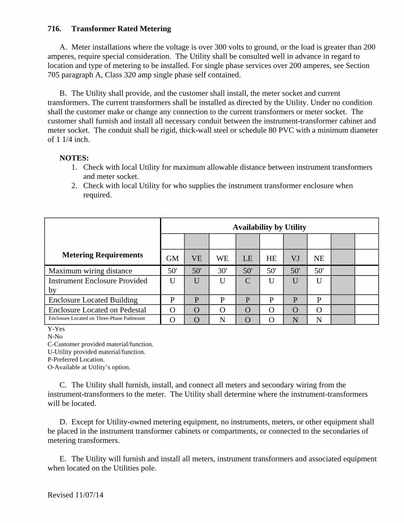
Revised 11/07/14
716. Transformer Rated Metering
A. Meter installations where the voltage is over 300 volts to ground, or the load is greater than 200 amperes, require special consideration. The Utility shall be consulted well in advance in regard to location and type of metering to be installed. For single phase services over 200 amperes, see Section 705 paragraph A, Class 320 amp single phase self contained.
B. The Utility shall provide, and the customer shall install, the meter socket and current transformers. The current transformers shall be installed as directed by the Utility. Under no condition shall the customer make or change any connection to the current transformers or meter socket. The customer shall furnish and install all necessary conduit between the instrument-transformer cabinet and meter socket. The conduit shall be rigid, thick-wall steel or schedule 80 PVC with a minimum diameter of 1 1/4 inch.
NOTES: 1. Check with local Utility for maximum allowable distance between instrument transformers
and meter socket. 2. Check with local Utility for who supplies the instrument transformer enclosure when
required.
Metering Requirements
Availability by Utility
GM VE WE LE HE
VJ
NE
Maximum wiring distance 50' 50' 30' 50' 50' 50' 50' Instrument Enclosure Provided by
U U U C U U U
Enclosure Located Building P P P P P P P Enclosure Located on Pedestal O O O O O O O Enclosure Located on Three-Phase Padmount O O N O O N N Y-Yes N-No C-Customer provided material/function. U-Utility provided material/function. P-Preferred Location. O-Available at Utility’s option.
C. The Utility shall furnish, install, and connect all meters and secondary wiring from the instrument-transformers to the meter. The Utility shall determine where the instrument-transformers will be located.
D. Except for Utility-owned metering equipment, no instruments, meters, or other equipment shall be placed in the instrument transformer cabinets or compartments, or connected to the secondaries of metering transformers.
E. The Utility will furnish and install all meters, instrument transformers and associated equipment when located on the Utilities pole.

Revised 11/07/14
717. Use of Instrument Transformer Enclosures
Instrument transformer enclosures shall not be used as junction boxes or for branch circuit wireways. Service conductors shall enter and leave the enclosure as one circuit with no branches, regardless of the number of conductors per phase. Line side connections to other meters shall not be made in the instrument transformer enclosure. Instrument transformer enclosures will be sealed or locked by the Utility.
718. Metal-Clad Switchgear Installations
The customer may, with Utility approval, install Utility-owned instrument transformers in metal-clad switchgear where this type of installation is contemplated. The Utility must be consulted for technical data on the instrument transformers that will be installed, and other engineering advice. Certain specifications in regard to metering transformer compartments are particularly important.
A. CT Compartment: A separate, sealable, and accessible compartment shall be provided within the switchgear for standard current transformers that will be furnished by the Utility and installed by the customer. This compartment shall be large enough to contain three current transformers and shall be so designed that after proper electrical isolation, the current transformers can be readily removed or changed after installation. Instrument transformer compartments shall contain only Utility-owned metering equipment and must be closed by hinged doors that are capable of being padlocked.
B. VT Compartment: Where metering voltage transformers are used, a separate, sealable, and accessible compartment shall be provided within a switchgear for standard voltage transformers of a type approved for metering by the Utility. This compartment shall be large enough to contain three voltage transformers. When the voltage transformers are stationary-mounted in the compartment, they shall be readily removable. When voltage transformers are mounted on a draw out carriage, the front of the carriage shall extend up to close the compartment when the transformers are in the operating position. Primary contacts for the draw out feature shall be of such design as will ensure continued maintenance of the contact pressure. Visible grounding devices shall be provided to make certain that the draw out carriage-mounted voltage transformer primary terminals are grounded when the carriage is withdrawn. 719. Sealing of Meters and Related Equipment
All meters and all points of access to unmetered wiring in a building shall be sealed by the Utility. All cabinets, switch boxes, and fittings used inside a building and containing unmetered wires shall be made sealable before service will be supplied. The breaking of seals by unauthorized persons or tampering with meters or any switches or wires in connection with the meter wiring is prohibited by Vermont law (13 VSA §§3782, 3784 & 2528). If it is necessary to break the seal to change or repair equipment, the customer shall contact the Utility to have authorized personnel remove, repair or replace the meter. When the job is completed, the Utility shall inspect the socket and replace the seal.

Revised 11/07/14
720. Meter Socket Specifications (See Drawing 601) 721. Meter Socket Concealment
The practice of enclosing meter sockets within small enclosures, in order to improve the appearance, is not encouraged. However, at the customers’ insistence, an enclosure may be allowed. Such an enclosure shall not conceal the service entrance cables for more than the thickness of the roof or floor of the enclosure (i.e. no more than one inch). The enclosure shall have a door that easily opens to allow meter reading. The door shall hinge on the left or the right. The enclosures door shall be high enough (32 inches min.) above grade so that snow build-up will not prevent the door from being opened. The enclosure shall be large enough to allow 8 inches on each side, top, and bottom, between the meter socket and the enclosure. The enclosure shall be not less than 16 inches deep and not more than 24 inches deep. Equipment, such as lawn tools, shall not be stored within the enclosure. Other devices, such as dryer vents or gas installations, shall not be installed inside the enclosure. Meter sockets shall not be inset into the building wall. The customer, not the Utility, is responsible for any damage that might occur, as the result of the Utility accessing the meter installation.

Revised 11/07/14
VIII. CUSTOMER EQUIPMENT
801. General
A. A customer may not utilize electric service in a manner that causes unusual fluctuations or
disturbances in the Utility’s supply system. Should the use of any equipment by a customer adversely
affect the Utility’s ability to render adequate service to other customers, the Utility reserves the right to
discontinue service until necessary corrections are made by the customer.
B. The equipment used by the customer shall:
1. Be suitable for operation on the service provided.
2. Have appropriate control devices.
3. Have power factor correction equipment as required.
4. Meet any applicable energy efficiency requirements.
5. Be installed to provide safe operation as defined by the NEC or local codes.
C. A customer must consult with the Utility in advance of making any commitments for large
motors, welders, X-ray machines, or other equipment that may have high instantaneous electrical
demand.
D. All loads shall be electrically balanced on three phase supply. Single phase loads shall be as
evenly divided as possible between the two energized conductors.
802. Motors
A. The Utility reserves the right to refuse service to the following:
1. Single phase motors larger than 5 horsepower. The Utility may authorize the use of single
phase motors larger than 5 horsepower if it concludes that the quality of service to others will
not be impaired.
2. The use of Polyphase motors larger than 5 horsepower operated from a single phase service
by use of a phase converter.
3. Polyphase motor installations totaling less than 5 horsepower. In those cases where the
customer proposes a limited amount of three phase equipment the Utility will require specific
permission to provide three phase, as opposed to single phase, service. A special equipment
charge to cover the cost of three phase transformers may be required.
Revised 11/07/14
4. The Utility further reserves the right to limit the size of the largest motor which may be
started across-the-line on any part of its system. Based on the Utility system capabilities, the
Utility may limit the maximum horsepower, the starting method, and the number of starts per
day. The starting of the motor should not result in a voltage fluctuation of more than 3%, as
measured at the point where other customers are affected. The limitation of 3% voltage
fluctuation is applicable to motors that start once per hour or less frequently. A lower
percentage voltage fluctuation shall be determined, by the Utility, in those cases where the
motor starts more frequently than once per hour. Technical questions regarding the starting
of large motors should be referred to the Utility’s Engineering Department.
B. Single phase motors shall meet the following requirements:
1. Motors with a rating of 2 horsepower or less may be connected to a 120 volt supply. Motors
with a rating larger than 2 horsepower should be connected to a 208 volt, or higher, supply.
Motors with a rating of 1 horsepower or larger, shall not be connected to a 120 volt supply.
2. Motors rated for 220, or more, volts may, or may not, operate properly at 208 volts.
3. Single phase service at 208 volts may not be available. Check with your local Utility. Single
phase service at 240 volts may not be available from a given transformer bank. Check with
your local Utility.
4. Single phase motors supplied from a three phase service shall be properly balanced across the
three phases. Exception: Single phase 120 volt motors are to be balanced across the two hot
legs on 240/120 volt services.
5. In residential installations, and for small commercial installations, the Utility shall be notified
prior to installing any motor larger than 2 horsepower.
C. Three phase motors shall meet the following requirements:
1. Motors rated at 10 horsepower or less, with locked rotor codes of A through G, may be
started across-the-line. For larger motors, the Utility reserves the right to require reduced
voltage starters or other acceptable starting means. The Utility may allow exceptions where
the system capabilities are sufficient. Such exceptions shall be documented in writing.
2. Motors rated for operation at 230 or 208-230 volts may, or may not, operate properly on a
208 volt system. When the supply is 208 volts, a motor with ratings of 200 or 208 volts
should operate properly.
D. Motor controls and protection shall be provided as follows:
1. Safety and Equipment Protection. It is the customer’s responsibility to provide over-current
and lockable disconnect devices as required by the NEC.
2. Single phasing protection. It is the customer’s responsibility to provide protection against the
possibility of loss of one or two phases on a three phase motor.

Revised 11/07/14
3. Phase reversal protection. It is the customer’s responsibility to provide protection against
phase reversal in those cases where such a reversal could result in injury or equipment
damage. In particular, but not limited to, passenger and freight elevators, cranes and hoists,
or other equipment that may require such protection.
4. Low voltage protection. It is the customer’s responsibility to provide protection against the
possibility of low voltage.
5. Electronic control protection. It is the customer’s responsibility to provide protection for the
electronic control equipment used with certain motors. This equipment may be sensitive to
commonly occurring system disturbances.
6. Harmonic Filtering. Rectifiers used with DC motors and other devices may cause harmonic
interference in the customer’s facility and on the Utility’s system. It is the customer’s
responsibility to provide filtering required to limit the effect of the interference.
E. Transformer Oversizing for Motor Starting may be necessary to reduce Voltage Flicker. If an
individual customer, with a large motor, is the only customer that receives objectionable flicker, then
that customer may be required to pay a Special Equipment Charge to offset the additional cost of a larger
transformer.
803. Auxiliary or Emergency Systems
A. Auxiliary or emergency systems are installed where customers have determined that a backup
source of electric power is required for the efficient or safe operation of their facility. The normal source
of electric power is provided by the Utility. The customer shall notify the Utility of the existence and
type of any auxiliary or emergency system.
B. Wiring. The auxiliary or emergency system shall be connected to the customer’s wiring such that
the Utility source cannot be tied to the auxiliary or emergency source. The customer shall be required to
connect the auxiliary source via a Utility-approved switching device. The double-throw switch or
transfer device shall be constructed and connected to prevent any possibility of power, from the
customer’s emergency source, feeding back into the Utility’s distribution system. The switch may be
either manual or automatic, (see Drawing 402).
804. Standby Service
A. Standby service is provided by the Utility for those customers that normally supply their electric
power with their own generator. The customer may be required to pay costs of installation and
maintenance of Utility standby equipment.
B. Wiring. The standby system shall be connected to the customer’s wiring such that the Utility
source cannot be tied to the customer’s source. The customer shall be required to connect the standby
source via an Utility approved switching device. The double-throw switch or transfer device shall be
constructed and connected to prevent any possibility of power, from the customer’s emergency source,
feeding back into the Utility’s distribution system. The switch may be either manual or automatic, (see
Drawing 402).
Revised 11/07/14
805. Customer Generation Operating in Parallel with the Utility System
A. This document is not intended to cover larger commercial generation facilities. See PSB Rule
5.500. What follows is intended to describe requirements for smaller customer generation facilities;
however, it is not intended to supersede PSB Rule 5.100.
B. A customer may request to operate a generation or co-generation system in parallel with the
Utility’s system. The Utility will determine if the installation can operate without hindrance to other
customers. Electricity produced by the customer for sale to the Utility shall be separately metered.
However, in certain circumstances, a ‘Net Metering Generation Connection’ may be available. See
paragraph 805G.
C. It is the customer’s responsibility to ensure that their installation meets all safety requirements. It
is the customer’s responsibility to provide equipment needed to protect the customer’s system. In
particular, the customer’s system shall be equipped to avoid damage that would occur if the Utility
experienced a brief outage followed by an immediate reclose to normal supply.
D. It is the customer’s responsibility to provide equipment to automatically isolate the customer’s
generation from the Utility system if system disturbances occur. This equipment shall include over-and-
under voltage relays, and over-and-under frequency relays, operating a customer’s breaker. Other
equipment may be required.
E. The cost of any equipment on or study of the Utility’s system necessary to allow the customer’s
system to operate in parallel shall be borne by the customer.
F. The customer shall provide a lockable disconnect switch which meets NEC requirements and is
accessible by first responders as per NEC requirements. This switch shall also be accessible by the
Utility’s employees, and may be used to prevent parallel operation under certain circumstances. Contact
your local utility as they may have additional requirements for the disconnect. The disconnect switch
shall be clearly marked ‘Generator Disconnect Switch’ with permanent letters, a minimum of 3/8 inch
high. The preferred location of the generator disconnect switch is that it be located outdoors within 10
feet of the Utility’s electric service meter. With your local utility’s approval, the generator disconnect
switch may be located in some other accessible location, however in this circumstance, there shall be a
placard placed at the service location giving directions to the location of the disconnect per NEC. The
disconnect switch must be lockable in the open position with a standard Utility padlock, with a 3/8 inch
shank.
1. The required non-Net Metering electrical connection is to connect the generation through a
separate generation meter, to the generator disconnect/breaker and on to the generator. The
generator disconnect/breaker must be listed as ‘Service Equipment’. The generation meter
will be either dual back-to-back meters with detented registers, or, a single meter with dual
registers. See Dwg 403.
2. The required non-Net Metering electrical connection is to connect the generation through the
service meter, to the main panel, to the generator disconnect and on to the generator. The
service meter will have a detented register, which will only measure delivered electricity.
This installation would be used for a customer that wants to ‘peak shave’. See Dwg. 404.
3. The recommended Net Metering electrical connection is to connect the disconnect switch to a
feeder breaker in the main panel, and then on to the generation source. See Dwg. 405.
Revised 11/07/14
4. An alternative Net Metering electrical connection is to connect the generation from the
service meter, to a generator disconnect/breaker, and on to the generator and the main panel
(sub-panel). The generator disconnect/breaker must be listed as ‘Service Equipment’. See
Dwg. 406.
5. Larger, three-phase, generators shall be connected through a three-phase gang-operated
loadbreak device. If the switching device does not have a visible break disconnect; then the
device shall be in series with a switch(s) that do have visible break. This disconnect switch is
not expected to be within 10 feet of the service meter.
G. Vermont Public Service Board Rule 5.100 specifies electrical connections, protection
requirements, operating rules and other aspects for ‘Net Metering Generation Connections’. Utilities
may adopt work practices and policies surrounding ‘Net Metering’ systems as long as they are consistent
with Rule 5.100. Check with your utility for their policies and practices.
806. Communications
A. Service for the operation of radio and television transmitting apparatus shall be furnished under
conditions specified by the Utility. Conditions of use of such service shall not cause disturbance to the
power supply of other customers or handicap the Utility in maintaining proper system conditions.
B. Where necessary, suitable eliminators or traps shall be installed by the customer in such manner
as to prevent radio, telephone, and television interference feeding back into the supply circuit.
C. Where service is required for a transmitting station or other high frequency equipment at a
specific location, it is essential that the Utility be consulted during early planning. Detailed technical
investigation shall be necessary before giving assurance of service to meet requirements.
D. Unauthorized attachment of antenna systems to Utility poles carrying Utility's conductors is
strictly prohibited due to the possibility of serious results from accidental contacts. Such attachments
shall be removed immediately upon discovery by the Utility at the customer's expense.
E. Outdoor antenna and lead-in conductors shall not cross over, but may cross under, electric light
or power circuits provided the conditions of the latest edition of the NEC are met.
F. If a customer's wiring is used for carrying current of a carrier system for remote control of power,
communication, or signaling purposes, there shall be installed suitable isolation/filter equipment
approved by the Utility to keep the Utility's distribution system free of any high frequency AC or DC
components produced by the customer's equipment.
G. Requests to install communication cables on poles for the distribution of high-frequency signals
employed in CATV systems shall be referred to the Utility in writing. All construction shall conform to
Utility Standards, the latest edition of the NEC Article 820, and any other regulations for CATV and/or
Communication Cable pole/line attachments.
Revised 11/07/14
807. Energy Management Systems
Customers installing an Energy Management System (EMS) should consult with the Utility if
they would like pulse signals from a pulse initiator to receive output from the Utility's meter. The
customer shall not receive an end-of-interval (EOI) signal. There shall be a charge for the installation
and maintenance of the pulse initiator. As ‘Smart Meters’ become available they may supersede EMS
systems.
808. Power Factor Correction
The use of equipment by the customer for power factor correction must conform to requirements
of the Utility as to electrical characteristics of equipment and its operation and control. The customer
may be required to limit the size of their static capacitor installation, or to maintain effective control of
the capacitors or other corrective equipment, in order to prevent the use of such equipment from causing
excessive voltage at the service. Corrective equipment installed by the customer must be located on the
load side of their service disconnecting device.
809. Alternating Current Arc Welders
A. The Utility reserves the right to refuse the supply of service to any AC arc welders which cause
interference or disturb the quality of service to other customers. They shall always be rated at not less
than 208 volts. The use of AC arc welders in conjunction with residence service and under residence
service rates will generally be restricted to limited input type with maximum welding current rating of
230 amperes and 20% duty cycle.
B. Spot welders shall not be installed on the company's lines without first obtaining the company's
permission.
810. Intermittently Operated Equipment
Flashing signs, photographer's illumination equipment, radio transmitters, and other similar
devices rated at more than 1,000 watts and which operate intermittently shall not be operated at 120
volts and shall be balanced between phase conductors. The Utility reserves the right to remove any
service which may cause interference or disturb the quality of service to other customers.
811. Heating Equipment
A. Heating devices rated at 1,650 watts or more shall be arranged for operation at 208 volts or
higher. The Utility reserves the right to require that industrial or commercial equipment rated at more
than 15 KW be arranged for operation on three phase, 208 volts, or higher.
B. Large single phase heating units, such as those associated with hydronic boilers and heat storage
units must be switched in increments of 12 KW or less, with a time delay of from 10 to 15 seconds.
812. Luminous Tube Signs and Lamps
Installations of more than 500 volt-amperes consisting of, or including, luminous tube signs
and/or lamps will be accepted for connection only when installed with sufficient power factor correction
equipment to maintain an overall power factor on the entire installation of not less than 90%.

Revised 11/07/14
813. Harmonic Distortion
The Utility recognizes the growing incidence of customers adding loads that result in harmonic
distortion. These harmonic distortions causing loads are devices such as computer power supplies,
compact fluorescent lights and variable speed drives. These devices draw a distorted current because
they include solid-state electronics that turn off current flow for part of every voltage cycle. This is often
referred to as a non-linear load. This distorted current flows back through the electric system causing a
voltage drop which results in all customers along the electric system receiving a distorted voltage. Some
degree of voltage distortion is considered acceptable, because it has limited consequences. The accepted
measure of acceptable harmonic voltage distortion is 3% of the fundamental 60Hz voltage for any
individual harmonic frequency and 5% Total Harmonic Distortion.

Revised 11/07/14
IX. GROUNDING 901. General Information
A permanent and effective grounding system furnished, installed, and maintained by the customer is an essential part of any two or three wire, single phase and any four wire, three phase installation . On three phase, three wire installations a common earth bonding connection must be used for equipment grounding.
A. The customer shall provide and maintain in good condition a suitable ground on all service equipment. All grounding of meter sockets, entrance switches, conduits, cables, equipment, etc., shall comply with the latest version of the NEC.
B. Grounding Electrodes and Ground Electrode Conductors shall be installed in accordance with the latest edition of the NEC.
C. The secondary circuits of current and potential instrument-transformers shall be grounded by the Utility only.
D. The cases, or frames, of instrument-transformers shall be grounded by the Utility.
E. The service entrance neutral conductor must be run to each individual service entrance switch, including the water heating service entrance switch, if any. It also must be connected to the grounded electrode in the service entrance cabinet.
F. All metallic pole risers and meter enclosures shall be effectively grounded.
G. The grounding electrode conductor shall be installed in one continuous length without splice or joint, unless spliced only by irreversible compression-type connectors listed for the purpose or by the exothermic welding process.

Revised 11/07/14
902. Grounding Electrode System
If available on the premises at each building or structure served, each item 1 through 4 below shall be bonded together to form the grounding electrode system:
1. Metal underground water pipe 2. Metal frame of the building (where effectively grounded) 3. Concrete-encased electrode 4. Ground ring- 30" deep
A metal underground water pipe shall be supplemented by an additional electrode (2, 3, or 4 above)
or a rod electrode of a type specified in Section 903. The ground wire shall be attached to the water-service pipe on the supply side of any shutoff or water meter. Reference should be made to National Electrical Code Section 250. On new structures, with new concrete footing or foundation, a concrete encased electrode is required to be installed. The electrode shall be encased by a minimum of 2 inches of concrete; and shall be located within and near the bottom of the footing or foundation. The electrode shall consist of at least 20 feet of one or more bare or zinc galvanized steel reinforcing rod (minimum 2" in diameter); or at least 20 feet of bare copper not smaller than #4 AWG. Reinforcing rods shall be permitted to be bonded together by the usual steel tie wires or other effective means. Connections shall be suitable for the location. Protect the electrode and Grounding Electrode Conductor, from corrosion at the exit from the footing or foundation. Reference should be made to National Electrical Code Section 250. 903. Ground Rods
Where none of the electrodes specified in Section 902 are available, two or more ground rods shall be used. Where practical, ground rods shall be embedded below permanent moisture level. Such electrodes shall be free from non-conductive coatings, such as paint or enamel. The use of ground rods shall not be an alternative to the required concrete encased electrodes in new structures. When driven ferrous ground rods are used, they shall be at least eight (8) feet long, and not smaller than 5/8 inch in diameter.
904. Ground Rod Installation
The ground rods shall be installed such that at least 8 feet of length is in contact with the soil. It shall be driven to a depth of not less than 8 feet except where rock bottom is encountered. The ground rods shall be driven at an oblique angle not to exceed 45 degrees from the vertical or shall be buried in a trench that is at least 22 feet deep. The upper end of the ground rods shall be flush with or below ground level unless the above ground end and the ground rod conductor attachment are protected against physical damage.
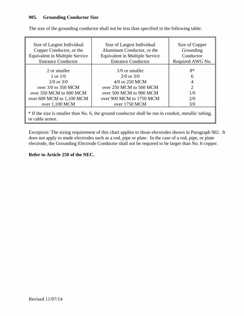
Revised 11/07/14
905. Grounding Conductor Size The size of the grounding conductor shall not be less than specified in the following table:
Size of Largest Individual Copper Conductor, or the
Equivalent in Multiple Service Entrance Conductor
Size of Largest Individual
Aluminum Conductor, or the Equivalent in Multiple Service
Entrance Conductor
Size of Copper
Grounding Conductor
Required AWG No.
2 or smaller 1 or 1/0
2/0 or 3/0 over 3/0 to 350 MCM
over 350 MCM to 600 MCM over 600 MCM to 1,100 MCM
over 1,100 MCM
1/0 or smaller
2/0 or 3/0 4/0 or 250 MCM
over 250 MCM to 500 MCM over 500 MCM to 900 MCM over 900 MCM to 1750 MCM
over 1750 MCM
8* 6 4 2
1/0 2/0 3/0
* If the size is smaller than No. 6, the ground conductor shall be run in conduit, metallic tubing, or cable armor. Exception: The sizing requirement of this chart applies to those electrodes shown in Paragraph 902. It does not apply to made electrodes such as a rod, pipe or plate. In the case of a rod, pipe, or plate electrode, the Grounding Electrode Conductor shall not be required to be larger than No. 6 copper. Refer to Article 250 of the NEC.

Revised 11/07/14
X. APPENDIX A - GLOSSARY
Ability to Serve - A letter indicating that the Utility can provide the electrical service requested
by an applicant in an Act 250 proceeding.
Act 250 - A Vermont law governing land development.
Alternating Current - Electric current that reverses the direction of its flow, as opposed to direct
current, which always flows in the same direction.
Ampere - The unit of measurement of electric current representing the flow of electrons
in a conductor past a given point in one second, similar to the measurement of
cubic feet of water flowing per second.
Approved Drawing - A final detailed drawing approved by the utility and provided to a line
extension applicant showing a proposed line extension.
Authorities - State and local government representatives that are legally empowered to
regulate or inspect the customer's installation or equipment.
AWG - American Wire Gauge.
Balanced Load - The same load on all phases.
CATV - Community Antenna Television, often referred to as cable TV.
Characteristics - Voltage rating, amperage rating, and number of phases.
Circuit Breaker - A device for protection and interruption of electrical current in a circuit.
Co-generation - An energy system providing both heat and power.
Conduit - Pipe used to protect electric wires or cables, generally underground.
Condulator - A cover providing protection against the elements where the conductors enter
an electrical-grade conduit.
Connectors - Devices for attaching wires.
Contribution-in-
aid-of-Construction - The amount a customer is required to pay the utility in advance before
construction of a line extension.
Current
Transformer (CT) - An instrument transformer, intended for measuring or control purposes, and
designed to have its primary winding connected in series with a conductor
carrying large alternating currents.
Customer - A present, or prospective, user of the Utility's electric service. Can be an
individual, contractor, or developer.
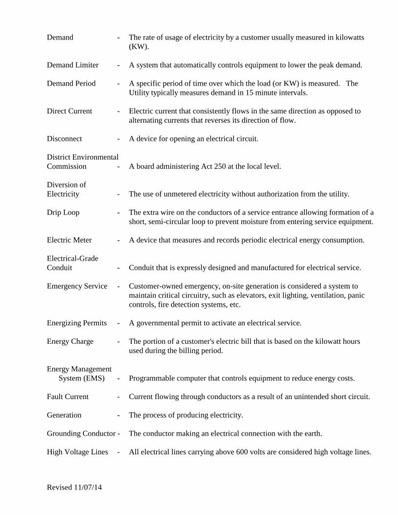
Revised 11/07/14
Demand - The rate of usage of electricity by a customer usually measured in kilowatts
(KW).
Demand Limiter - A system that automatically controls equipment to lower the peak demand.
Demand Period - A specific period of time over which the load (or KW) is measured. The
Utility typically measures demand in 15 minute intervals.
Direct Current - Electric current that consistently flows in the same direction as opposed to
alternating currents that reverses its direction of flow.
Disconnect - A device for opening an electrical circuit.
District Environmental
Commission - A board administering Act 250 at the local level.
Diversion of
Electricity - The use of unmetered electricity without authorization from the utility.
Drip Loop - The extra wire on the conductors of a service entrance allowing formation of a
short, semi-circular loop to prevent moisture from entering service equipment.
Electric Meter - A device that measures and records periodic electrical energy consumption.
Electrical-Grade
Conduit - Conduit that is expressly designed and manufactured for electrical service.
Emergency Service - Customer-owned emergency, on-site generation is considered a system to
maintain critical circuitry, such as elevators, exit lighting, ventilation, panic
controls, fire detection systems, etc.
Energizing Permits - A governmental permit to activate an electrical service.
Energy Charge - The portion of a customer's electric bill that is based on the kilowatt hours
used during the billing period.
Energy Management
System (EMS) - Programmable computer that controls equipment to reduce energy costs.
Fault Current - Current flowing through conductors as a result of an unintended short circuit.
Generation - The process of producing electricity.
Grounding Conductor - The conductor making an electrical connection with the earth.
High Voltage Lines - All electrical lines carrying above 600 volts are considered high voltage lines.

Revised 11/07/14
Inspector - An individual representing a government agency, or the Utility, who is
qualified to determine if electrical installation requirements have been met.
Junction Box - An enclosure for the connection of one or more electrical circuits.
Kilowatt (KW) - A unit of electrical work equal to 1,000 watts comparable to ten 100-watt light
bulbs.
Kilowatt
Hour (KWH) - A basic unit of measuring electricity consumption, equal to the use of ten 100-
watt bulbs for one hour.
KVA - Kilovolt-amperes, often referred to as apparent power.
Line - A system used for the general distribution of electricity.
Line Extension - Addition to the Utility's distribution system necessary to provide service to a
customer.
Load Data - Information that refers to the size, phase, voltage, and expected
consumption of both energy and demand for a particular
electrical service.
Load Management - Efforts of a Utility and its customers to shift electrical usage
away from period of high demand to lower costs.
MCM - Thousand-Circular-Mills (size of cable).
Megawatt (MW) - One thousand kilowatts.
Megawatt
Hour (MWH) - One thousand kilowatts used for one hour.
Meter Socket - The enclosure that houses the electric service conductors and
provides the mechanism for connection of the service to the
electric meter.
Meter Pedestal - A supporting, upright structure for the attachment of metering.
Mobile Home - “A factory-assembled structure or structures, transportable in one
or more sections, that is built on a permanent chassis and
designed to be used as a dwelling without a permanent
foundation where connected to the required utilities and includes
the plumbing, heating, air conditioning, and electric systems
contained therein”, NEC 550.2.
Mobile Home Park - “A contiguous parcel of land that is used for the accommodation
of occupied mobile homes”, NEC 550.2.
Revised 11/07/14
National Electrical
Code (NEC) - A nationally-accepted guide for the safe installation of electrical
wiring and equipment published by the NFPA.
National Electrical
Safety Code (NESC) - Safety procedures governing all electrical work done on the
Utility system.
NEMA - National Electrical Manufacturers Association.
Net Metering - As defined by PSB Rule 5.100.
Net Metering
Generation Connection- The use of a single meter at a customer with both
outgoing (load), and incoming (generated), energy. The meter
runs backwards when the customer is generating more energy
than it is using.
Neutral - A grounded conductor that carries current resulting from an
unbalanced load.
NFPA - National Fire Protection Association.
Overload Protection - Interruption of current under conditions of excessive demand, or
fault.
Peak Demand - The highest measured KW load for any typical 15 minute interval
during a billing period.
Point-of-Service - The point at which the Utility ownership terminates its
(Attachment) service lateral and the customer begins their wiring.
Power Factor - The ratio of real power measured in kilowatts (KW) to apparent
power measured in kilovoltampere (KVA) for any given load and
time. Generally expressed as a percentage.
Primary Service - Power at primary voltage.
Primary Voltage - High voltages used in transmission and distribution systems.
Pull Box - A box with a blank cover for installing conductors into a conduit
run, raceway, or metallic tubing which facilitates the installation
of conductors.
Right-of-Way
Easement (R-O-W) - A right acquired by the Utility to use land belonging to another
for the construction, operation, and maintenance of electric
facilities.
Revised 11/07/14
Seals - Devices with various identifying marks and colors which secure
electric meters and associated equipment.
Secondary Service - Power at secondary voltage between transformer and the Utility-
owned equipment such as a pole or pedestal.
Secondary Voltage - 600 volts or less.
Service Drop - The overhead service conductors furnished by the Utility
between the last pole, or other aerial support, and the first point
of attachment to the building or intermediate support.
Service Entrance - The part of the service which runs from the point of attachment
of the overhead service drop on the building to the service
entrance equipment. The service entrance conductors shall be
sized and installed in accordance with the National Electrical
Code.
Service Equipment - The necessary equipment (usually consisting of circuit breaker,
or switch and fuses, and their accessories) located near the point
of entrance of supply conductors to a building intended to
constitute the main control and means of cutoff for the supply to
the premises.
Single Phase - Wiring used on a circuit is supplied by only one of the three
phase conductors available from the primary distribution system.
Site Plan - A detailed drawing of a parcel of land indicating relevant
elevations, buildings, and Utilities.
Smart Meter - A metering system with two-way communication which may
have abilities to provide additional services to the customer.
Stand-by Service - Electrical service provided by the utility for customers generally
using a co-generation or self-generation system.
Starting
Compensators - Devices that limit the maximum current drawn when a motor is
started.
Stray Voltage - The voltage between the wiring system=s neutral conductor and
surfaces intimately contacting earth. Because return current
flows on the system neutral conductor, the neutral will have a
voltage different than earth potential due to voltage drop.
Structure - For the purposes of code enforcement – That which is built or
constructed. A pole, pedestal or similar support used exclusively
by a utility, to support utility meter enclosures or combination of
meter enclosure and overcurrent devices, shall not be considered
to be a structure.

Revised 11/07/14
Switch Gear - Metal enclosed equipment normally consisting of interrupter
switches and fuses plus control and sensing devices, which
allows for connections between circuits.
Temporary Service - A minimum service provided solely for construction purposes.
Three Phase - The wiring used on a circuit is supplied by all three of the phase
conductors available from the primary distribution system.
Time of Use (TOU) - A method of metering with different charges for
specified times.
Transfer Switches - Switches that operate so that power is provided from one of two
possible sources.
Transformer - Equipment designed to increase or decrease voltage.
Transmission - The delivery of electricity over lines from a generation source to
a distribution point.
UD - Underground distribution.
URD - Underground Residential Distribution.
Vermont Department
of Public Service - The agency of state government which functions as the public
advocate in proceedings before the Public Service Board.
Vermont Public
Service Board - The three-person, quasi-judicial body, appointed by the governor
of Vermont, which approves rates and generally oversees the
public electric Utilities in Vermont.
Volt - The unit of electromotive force or electric pressure through a
conductor or circuit, similar to water pressure measured in
pounds per square inch.
Voltage
Transformer (VT) - A small capacity instrument transformer used to reduce voltage
to supply electrical equipment. The primary winding is connected
in parallel with the circuit whose voltage is to be measured or
controlled.
Weatherhead - A cover mounted on the highest point of the service
entrance cable to prevent water from flowing down the
cable into the meter socket.
Wiring Permit - Authorization to install new wiring or equipment by
(Work Notice) extending an existing circuit or adding a new one.

DRAWINGS
VERMONT UTILITIES ELECTRIC
SERVICE REQUIREMENTS
App’d: YES
DATE: 11/14 100pg1c.doc
DRAWING NUMBER 100 Page 1
Drawing Applicability
Availability by Utility
GM VE WE LE HE VJ NE Overhead Service Dwg. 101 A A A A A A A
Mast Service Dwg 102 A A A A A A A
Underground Service Dwg 201 A1 O A A1 A1 A A
Pole Metering Dwg. 202 O O N N O O O
Trench Dwg. 203 A A A A A A A
Typical Meter Pedestal Dwg. 204 A3 O A A1 A1 A A
Meter Pedestal Current Transf. Dwg. 205 O O O O O O O
Multiple Meter Pedestal Dwg. 206 O O O O O O O
Typical Temporary Service Dwg. 301 A A N A A A A
Temporary Underground Service Dwg. 302 A O A O O A A
Typical Temporary Service Dwg. 303 O A A A A O N
Gas/Meter Clearance Dwg. 401 A A A A A A A
Emergency Supply Dwg. 402 A A A A A A A Non-Net Metering Generation Connection Dwg. 403 A A A A A A A Non-Net Metering Peak Shaving Generation Dwg. 404 A A A A A A A Net Metering Generation Connection Dwg. 405 A A A A A A A Net Metering Generation Connection Alternate Dwg. 406 A A A A A A A
Customer Load Data Dwg. 501 A A A A A A A Fault Current Request Dwg. 502 A A A A A A A Meter Socket Spec. Dwg. 601 A A A A A A A Single Phase Meter Installation Dwg. 602 A A A A A A A Polyphase Meter Installation Dwg. 603 A A A A A A A Transformer Rated Meter Inst. Dwg. 604 A A A A A A A
A-Fully Applies N-Does Not Apply O-Available at Utility’s option. A1- Applies with the exception that the chart below substitutes for the chart on the drawing. A2- Applies with the exception that the chart below substitutes for the chart on the drawing. Available in limited circumstances at the Utility’s option. A3- Applies with the exception that the chart below substitutes for the chart on the drawing. Available in limited circumstances at the Utility’s option. See GMP Distribution Standard 1647 for details.
RESIDENTIAL 120/240 VOLT SERVICES ONLY
RATING CABLE LENGTH* TRIPLEX SIZE CONDUIT
100A 0-140 FT #2** 2-1/2"***
0-210 FT 1/0 2-1/2"***
211-270 FT 2/0 2-1/2"
271-410 FT 4/0 2-1/2"
411-650 FT 350 MCM 3"
651-890 FT 500 MCM ** 3"
150A 0-175 FT 2/0 2-1/2"
176-275 FT 4/0 2-1/2"
276-435 FT 350 MCM 3"
436-590 FT 500 MCM ** 3"
200A 0-205 FT 4/0 2-1/2"
206-325 FT 350 MCM 3"
326-440 FT 500 MCM ** 3"
300A 0-220 FT 350 MCM 3"
221-295 FT 500 MCM 3"
* Cable Length is the total of trench and riser lengths. This chart does not indicate that the cable can be pulled
into conduits of these lengths. Pulling calculations are necessary to make that determination.
** Customer Owned Services Only
*** 2" NEMA Schedule 80 conduit may be used on the riser pole. Customer owned only.
Double cable runs (eg. two runs of 4/0 cable) will allow a double length cable run. A minimum
of double #2 is required for 150A. A minimum of double 2/0 is required for 200A.
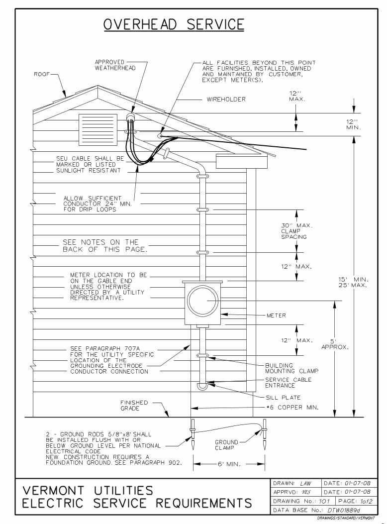

OVERHEAD SERVICE
VERMONT UTILITIES ELECTRIC
SERVICE REQUIREMENTS
App’d: YES DATE: 02/10 101PG2D.DOC
DRAWING NUMBER 101 Page 2
Notes: 1. All wiring and materials shall conform to the requirements of the National Electric Code (NEC) and to any applicable local codes. Where conflict exists the more stringent code will apply. For customer owned equipment, any requirements in excess of code specified minimums, are recommended not required. 2. The point of attachment of the service drop and the location of the meter socket will be designated by the utility representative. Any relocation shall be approved by a utility representative. 3. On low buildings, without the minimum 15 ft clearance, a mast installation shall be required (refer to mast installation drawing). 4. The service drop will not be allowed to be attached on or under the eaves. 5. In areas subject to truck traffic, the clearance required to the service drop, is a minimum of 16 ft, under the ice loading conditions described in the National Electric Safety Code (NESC). If the overhead service is owned by the customer, rather than the utility, the clearance required is a minimum of 18 ft under the conditions described in the NEC (no loading at 60E F). In areas only subject to pedestrian traffic, the clearance required to the service drop, is a minimum of 12 ft, under the ice loading conditions described in the NESC. 6. Residential 320 amp meter sockets, and all commercial meter sockets, shall have a manual bypass. For Utility-specific details see Paragraph 705E. See Paragraph 707 for requirements and Utility-specific details of how a Service Grounding Connection is to be made. See the Meter Socket Specification (Dwg 601) included in this manual.
7. The grounding electrode conductor, to a driven ground, shall be a minimum of #6 copper. The conductor shall be adequately protected. The driven rods shown shall be a minimum of 5/8" in diameter and 8' long. See Paragraph 901 through 905 for details of the Service Ground. 8. All gas valves shall be a minimum of 10 ft from electric meter equipment. For clearances less than 10 ft see Dwg. 401 and NFPA 58. 9. The Service Disconnecting Means shall be installed at a readily accessible location, either outside of a building or structure, or, inside a building or structure nearest the point of entrance of the service conductors, not to exceed 10 feet of conductor length, from the point of entrance.
10. The service drop cable and its drip loop shall have a clearance of 3 ft from any accessible opening such as to the side of an openable window, to the top of a doorway to a balcony, or to the side of a fire escape. No clearance is required directly above a window. If the opening is used for access for people or materials, then service cables shall not be placed below the opening. See NEC Article 230.9. 11. All services, unless the exceptions of Notes 12 or 13 apply, shall have a clearance of 10 ft, from the roof. That clearance is required above the roof and 3 ft beyond the edge of the roof. The service drop may attach to the side of the building.
12. For roofs easily accessible to pedestrian or vehicular traffic, clearances are those required above ground surfaces. See Note 5. 13. For inaccessible roofs with a slope of 4 on 12, or steeper, and voltages less than 300 volts between conductors, the clearance to the roof may be reduced to 3 ft. A roof is considered accessible if it can be accessed by a window or permanently mounted ladder.

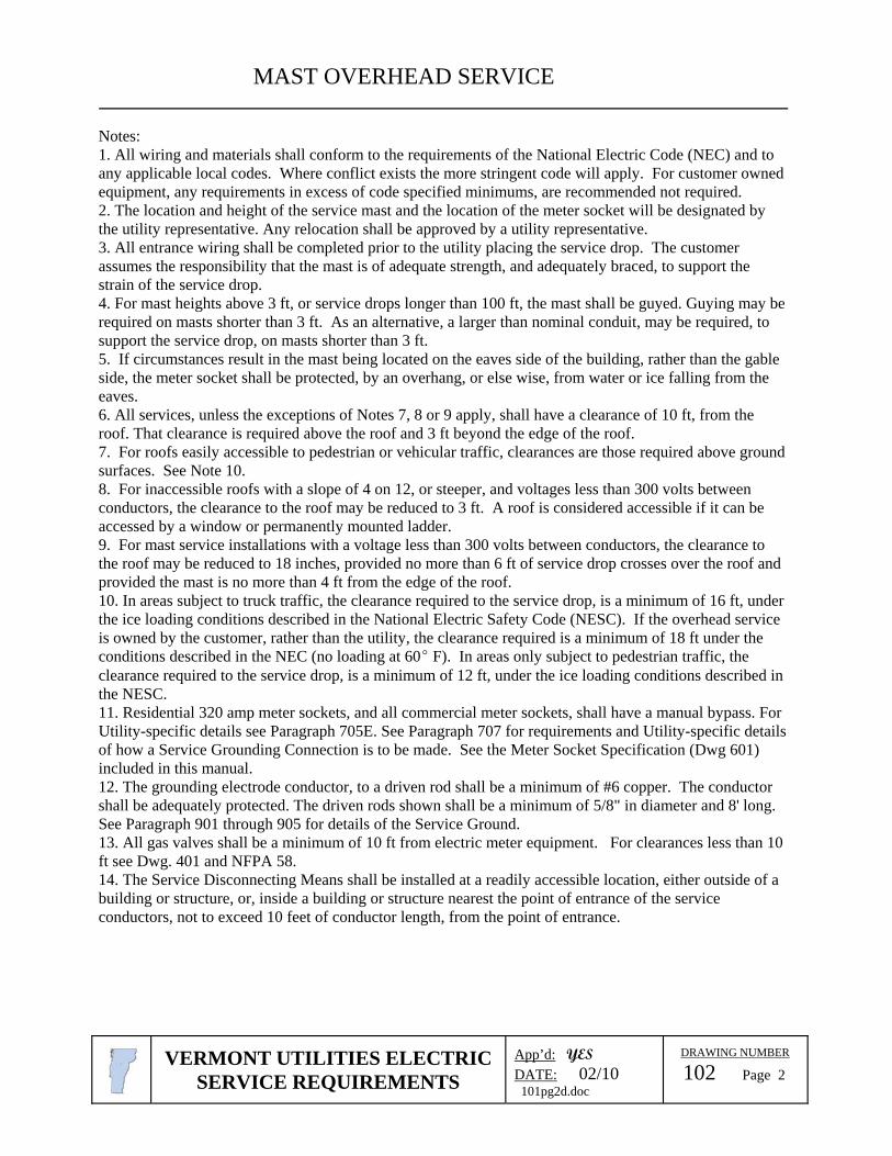
MAST OVERHEAD SERVICE
VERMONT UTILITIES ELECTRIC
SERVICE REQUIREMENTS
App’d: YES DATE: 02/10 101pg2d.doc
DRAWING NUMBER 102 Page 2
Notes: 1. All wiring and materials shall conform to the requirements of the National Electric Code (NEC) and to any applicable local codes. Where conflict exists the more stringent code will apply. For customer owned equipment, any requirements in excess of code specified minimums, are recommended not required. 2. The location and height of the service mast and the location of the meter socket will be designated by the utility representative. Any relocation shall be approved by a utility representative. 3. All entrance wiring shall be completed prior to the utility placing the service drop. The customer assumes the responsibility that the mast is of adequate strength, and adequately braced, to support the strain of the service drop. 4. For mast heights above 3 ft, or service drops longer than 100 ft, the mast shall be guyed. Guying may be required on masts shorter than 3 ft. As an alternative, a larger than nominal conduit, may be required, to support the service drop, on masts shorter than 3 ft. 5. If circumstances result in the mast being located on the eaves side of the building, rather than the gable side, the meter socket shall be protected, by an overhang, or else wise, from water or ice falling from the eaves. 6. All services, unless the exceptions of Notes 7, 8 or 9 apply, shall have a clearance of 10 ft, from the roof. That clearance is required above the roof and 3 ft beyond the edge of the roof. 7. For roofs easily accessible to pedestrian or vehicular traffic, clearances are those required above ground surfaces. See Note 10. 8. For inaccessible roofs with a slope of 4 on 12, or steeper, and voltages less than 300 volts between conductors, the clearance to the roof may be reduced to 3 ft. A roof is considered accessible if it can be accessed by a window or permanently mounted ladder. 9. For mast service installations with a voltage less than 300 volts between conductors, the clearance to the roof may be reduced to 18 inches, provided no more than 6 ft of service drop crosses over the roof and provided the mast is no more than 4 ft from the edge of the roof. 10. In areas subject to truck traffic, the clearance required to the service drop, is a minimum of 16 ft, under the ice loading conditions described in the National Electric Safety Code (NESC). If the overhead service is owned by the customer, rather than the utility, the clearance required is a minimum of 18 ft under the conditions described in the NEC (no loading at 60E F). In areas only subject to pedestrian traffic, the clearance required to the service drop, is a minimum of 12 ft, under the ice loading conditions described in the NESC. 11. Residential 320 amp meter sockets, and all commercial meter sockets, shall have a manual bypass. For Utility-specific details see Paragraph 705E. See Paragraph 707 for requirements and Utility-specific details of how a Service Grounding Connection is to be made. See the Meter Socket Specification (Dwg 601) included in this manual.
12. The grounding electrode conductor, to a driven rod shall be a minimum of #6 copper. The conductor shall be adequately protected. The driven rods shown shall be a minimum of 5/8" in diameter and 8' long. See Paragraph 901 through 905 for details of the Service Ground. 13. All gas valves shall be a minimum of 10 ft from electric meter equipment. For clearances less than 10 ft see Dwg. 401 and NFPA 58. 14. The Service Disconnecting Means shall be installed at a readily accessible location, either outside of a building or structure, or, inside a building or structure nearest the point of entrance of the service conductors, not to exceed 10 feet of conductor length, from the point of entrance.


UNDERGROUND SERVICE
VERMONT UTILITIES ELECTRIC
SERVICE REQUIREMENTS
App’d: YES DATE: 02/10 201pg3b.doc
DRAWING NUMBER 201 Page 3
Notes: 1. All wiring and materials shall conform to the requirements of the National Electric Code (NEC) and to any applicable local codes. Where conflict exists the more stringent code will apply. For customer owned equipment, any requirements in excess of code specified minimums, are recommended not required. 2. This specification covers residential services. Commercial service equipment is under the jurisdiction of the electrical inspector. The cable sizes shown in the chart may not apply to commercial services. 3. The location of the conduit risers and the meter socket will be designated by the utility representative. Any relocation shall be approved by a utility representative. 4. Conduit Condulators may be required for multi-conductor services and for conductors of 350 MCM or larger. Exercise care in limiting water entry. 5. Locate the riser conduit on the quarter of the pole away from normal traffic. 6. Residential 320 amp meter sockets, and all commercial meter sockets, shall have a manual bypass. For Utility-specific details see Paragraph 705E. See Paragraph 707 for requirements and Utility-specific details of how a Service Grounding Connection is to be made. See the Meter Socket Specification (Dwg 601) included in this manual. 7. The grounding electrode conductor, to a driven ground, shall be a minimum of #6 copper. The conductor shall be adequately protected. The driven grounds shown shall be a minimum of 5/8" in diameter and 8' long. See Paragraph 901 through 905 for details of the Service Ground. 8. Any steel conduit within 18" of the surface shall be bonded. Steel conduit is not required. 9. Any construction, at the pole, above ground level, shall be done by the utility company. Exception: The customer may install that portion of their equipment that can be reached while standing on the ground. Any trench near the base of the pole shall be immediately backfilled and properly tamped. 10. Depths shallower than 36" may be allowed where obstructions such as ledge are encountered. Any portion of conduit shallower than 24" shall be covered by a minimum 2" concrete cap. See the utility for additional requirements for conduit buried near underground facilities, under driveways or roadways, or, for depths shallower than 12". 11. All gas valves shall be a minimum of 10 ft from electric meter equipment. For clearances less than 10 ft see Dwg. 401 and NFPA 58. 12. The Service Disconnecting Means shall be installed at a readily accessible location, either outside of a building or structure, or, inside a building or structure nearest the point of entrance of the service conductors, not to exceed 10 feet conductor length, from the point of entrance. 13. The chart shows the acceptable total cable length for given service amp ratings and conductors. The chart is based on a maximum 3% voltage drop in an aluminum underground service cable for a 120/240 volt service. For other voltages, cables or multiple cables consult your local utility. 14. A marker tape shall be installed, above the conduit, 12 inches below grade. Type USE cable shall be marked or listed sunlight resistant. 15. A side bus bar meter socket is required if 350MCM cable is used. 16. URD Service Risers, from a pole-mounted three-phase transformer bank, shall be limited to an 800 amp rating. Larger services shall be supplied by a padmounted transformer. 17. Customer must provide sufficient cable to reach the transformer or secondary cable and to make connections.
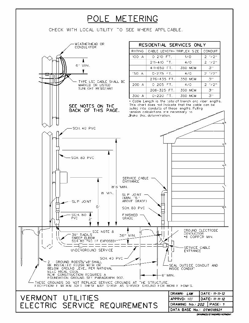

POLE METERING
VERMONT UTILITIES ELECTRIC
SERVICE REQUIREMENTS
App’d: YES DATE: 02/10 202pg2d.doc
DRAWING NUMBER 202 Page 2
Notes: 1. All wiring and materials shall conform to the requirements of the National Electric Code (NEC) and to any applicable local codes. Where conflict exists the more stringent code will apply. For customer owned equipment, any requirements in excess of code specified minimums, are recommended not required. 2. This specification covers residential services. Commercial service equipment is under the jurisdiction of the electrical inspector. The cable sizes shown in the chart may not apply to commercial services. 3. The location of the conduit risers and the meter socket will be designated by the utility representative. Any relocation shall be approved by a utility representative. 4. Conduit Condulators may be required for multi-conductor services and for conductors of 350 MCM or larger. Exercise care in limiting water entry. 5. Locate the riser conduit on the quarter of the pole away from normal traffic. 6. Residential 320 amp meter sockets, and all commercial meter sockets, shall have a manual bypass. For Utility-specific details see Paragraph 705E. The meter socket shall have a separate grounding electrode conductor connector. The connector shall be appropriately connected to the service neutral bus. The service neutral, and not the grounding electrode conductor, shall extend from the meter socket to the main disconnect in the building. An exception would occur if a breaker, under the meter socket, is the main disconnect for a mobile home. See the Meter Socket Specification (Dwg. 601) included in this manual. 7. The grounding electrode conductor, from the main disconnect, to a driven ground, shall be a minimum of #6 copper. The conductor shall be adequately protected. The driven grounds shown shall be a minimum of 5/8" in diameter and 8' long. See Paragraph 901 through 905 for details of the Service Ground. 8. Any steel conduit within 18" of the surface shall be bonded. Steel conduit is not required. 9. Any construction, at the pole, above ground level, shall be done by the utility company. Exception: The customer may install that portion of their equipment that can be reached while standing on the ground. Any trench near the base of the pole shall be immediately backfilled and properly tamped. 10. Depths shallower than 36" may be allowed where obstructions such as ledge are encountered. Any portion of conduit shallower than 24" shall be covered by a minimum 2" concrete cap. See the utility for additional requirements for conduit buried near underground facilities, under driveways or roadways, or, for depths shallower than 12". 11. All gas valves shall be a minimum of 10 ft from electric meter equipment. For clearances less than 10 ft see Dwg. 401 and NFPA 58. 12. The Service Disconnecting Means shall be installed at a readily accessible location, either outside of a building or structure, or, inside a building or structure nearest the point of entrance of the service conductors, not to exceed 10 feet of conductor length, from the point of entrance. 13. The chart shows the acceptable total cable length for given service amp ratings and conductors. The chart is based on a maximum 3% voltage drop in an aluminum underground service cable for a 120/240 volt service. For other voltages, cables or multiple cables consult your local utility. The chart is a recommendation, rather than a requirement, in the case of Pole Metering. However, failure to follow these recommendations can cause damage or malfunction of the customer’s equipment. The Utility does not accept any liability for loss or damage incurred as a result of said failure, and, the customer proceeds at his own risk. The conduit attached to the pole shall meet the chart’s size, for the cable chosen by the customer. The cable size shall, at a minimum, meet the ampacity of the customer’s disconnect. 14. A marker tape shall be installed, above the conduit, 12 inches below grade. Type USE cable shall be listed or marked sunlight resistant. 15. The decision to allow pole metering is solely at the Utility’s discretion. The pole shall be in a location that is protected from pedestrian and vehicular traffic. The pole shall be in a location that is convenient for meter reading. The pole shall not be encumbered with equipment, primary taps or other risers, that make future pole replacements difficult. Pole metering is not available for customers with multiple service rates, or, for customers with time-of-day rates controlled by a relay in the meter.
16. The Utility recommends that the customer install an integral breaker/meter socket. The purpose of the breaker is to allow the customer to maintain their underground service without an expensive linecrew visit. Check with your Utility to determine whether the breaker is required.


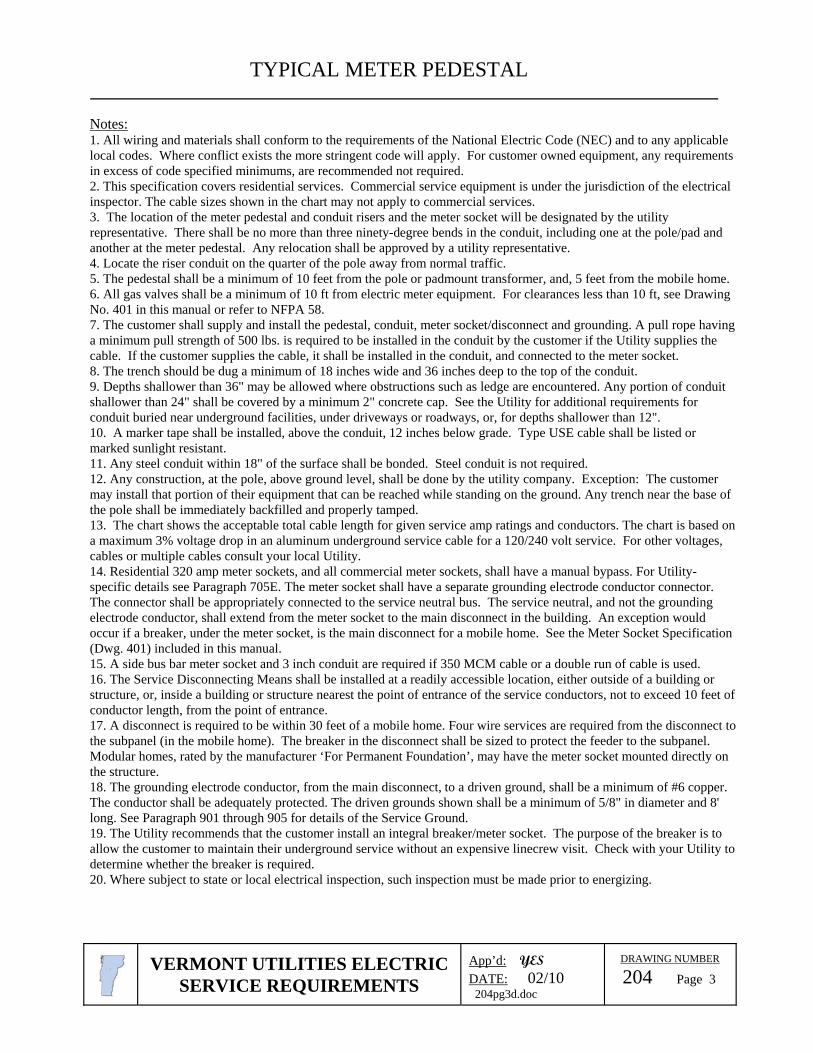
TYPICAL METER PEDESTAL
VERMONT UTILITIES ELECTRIC
SERVICE REQUIREMENTS
App’d: YES DATE: 02/10 204pg3d.doc
DRAWING NUMBER 204 Page 3
Notes: 1. All wiring and materials shall conform to the requirements of the National Electric Code (NEC) and to any applicable local codes. Where conflict exists the more stringent code will apply. For customer owned equipment, any requirements in excess of code specified minimums, are recommended not required. 2. This specification covers residential services. Commercial service equipment is under the jurisdiction of the electrical inspector. The cable sizes shown in the chart may not apply to commercial services. 3. The location of the meter pedestal and conduit risers and the meter socket will be designated by the utility representative. There shall be no more than three ninety-degree bends in the conduit, including one at the pole/pad and another at the meter pedestal. Any relocation shall be approved by a utility representative. 4. Locate the riser conduit on the quarter of the pole away from normal traffic. 5. The pedestal shall be a minimum of 10 feet from the pole or padmount transformer, and, 5 feet from the mobile home. 6. All gas valves shall be a minimum of 10 ft from electric meter equipment. For clearances less than 10 ft, see Drawing No. 401 in this manual or refer to NFPA 58. 7. The customer shall supply and install the pedestal, conduit, meter socket/disconnect and grounding. A pull rope having a minimum pull strength of 500 lbs. is required to be installed in the conduit by the customer if the Utility supplies the cable. If the customer supplies the cable, it shall be installed in the conduit, and connected to the meter socket. 8. The trench should be dug a minimum of 18 inches wide and 36 inches deep to the top of the conduit. 9. Depths shallower than 36" may be allowed where obstructions such as ledge are encountered. Any portion of conduit shallower than 24" shall be covered by a minimum 2" concrete cap. See the Utility for additional requirements for conduit buried near underground facilities, under driveways or roadways, or, for depths shallower than 12". 10. A marker tape shall be installed, above the conduit, 12 inches below grade. Type USE cable shall be listed or marked sunlight resistant. 11. Any steel conduit within 18" of the surface shall be bonded. Steel conduit is not required. 12. Any construction, at the pole, above ground level, shall be done by the utility company. Exception: The customer may install that portion of their equipment that can be reached while standing on the ground. Any trench near the base of the pole shall be immediately backfilled and properly tamped. 13. The chart shows the acceptable total cable length for given service amp ratings and conductors. The chart is based on a maximum 3% voltage drop in an aluminum underground service cable for a 120/240 volt service. For other voltages, cables or multiple cables consult your local Utility. 14. Residential 320 amp meter sockets, and all commercial meter sockets, shall have a manual bypass. For Utility-specific details see Paragraph 705E. The meter socket shall have a separate grounding electrode conductor connector. The connector shall be appropriately connected to the service neutral bus. The service neutral, and not the grounding electrode conductor, shall extend from the meter socket to the main disconnect in the building. An exception would occur if a breaker, under the meter socket, is the main disconnect for a mobile home. See the Meter Socket Specification (Dwg. 401) included in this manual. 15. A side bus bar meter socket and 3 inch conduit are required if 350 MCM cable or a double run of cable is used. 16. The Service Disconnecting Means shall be installed at a readily accessible location, either outside of a building or structure, or, inside a building or structure nearest the point of entrance of the service conductors, not to exceed 10 feet of conductor length, from the point of entrance. 17. A disconnect is required to be within 30 feet of a mobile home. Four wire services are required from the disconnect to the subpanel (in the mobile home). The breaker in the disconnect shall be sized to protect the feeder to the subpanel. Modular homes, rated by the manufacturer ‘For Permanent Foundation’, may have the meter socket mounted directly on the structure. 18. The grounding electrode conductor, from the main disconnect, to a driven ground, shall be a minimum of #6 copper. The conductor shall be adequately protected. The driven grounds shown shall be a minimum of 5/8" in diameter and 8' long. See Paragraph 901 through 905 for details of the Service Ground.
19. The Utility recommends that the customer install an integral breaker/meter socket. The purpose of the breaker is to allow the customer to maintain their underground service without an expensive linecrew visit. Check with your Utility to determine whether the breaker is required. 20. Where subject to state or local electrical inspection, such inspection must be made prior to energizing.
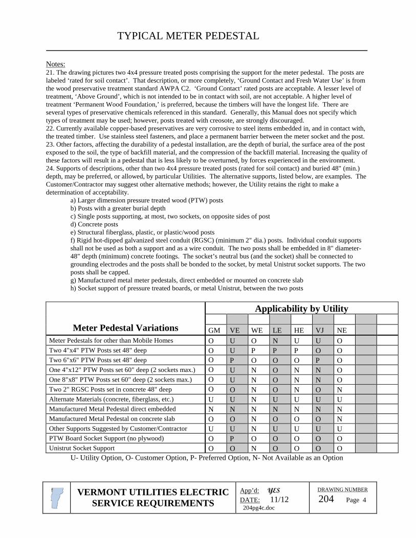
TYPICAL METER PEDESTAL
VERMONT UTILITIES ELECTRICSERVICE REQUIREMENTS
App’d: YES
DATE: 11/12204pg4c.doc
DRAWING NUMBER
204 Page 4
Notes:21. The drawing pictures two 4x4 pressure treated posts comprising the support for the meter pedestal. The posts arelabeled ‘rated for soil contact’. That description, or more completely, ‘Ground Contact and Fresh Water Use’ is fromthe wood preservative treatment standard AWPA C2. ‘Ground Contact’ rated posts are acceptable. A lesser level oftreatment, ‘Above Ground’, which is not intended to be in contact with soil, are not acceptable. A higher level oftreatment ‘Permanent Wood Foundation,’ is preferred, because the timbers will have the longest life. There areseveral types of preservative chemicals referenced in this standard. Generally, this Manual does not specify whichtypes of treatment may be used; however, posts treated with creosote, are strongly discouraged.22. Currently available copper-based preservatives are very corrosive to steel items embedded in, and in contact with,the treated timber. Use stainless steel fasteners, and place a permanent barrier between the meter socket and the post.23. Other factors, affecting the durability of a pedestal installation, are the depth of burial, the surface area of the postexposed to the soil, the type of backfill material, and the compression of the backfill material. Increasing the quality ofthese factors will result in a pedestal that is less likely to be overturned, by forces experienced in the environment.24. Supports of descriptions, other than two 4x4 pressure treated posts (rated for soil contact) and buried 48" (min.)depth, may be preferred, or allowed, by particular Utilities. The alternative supports, listed below, are examples. TheCustomer/Contractor may suggest other alternative methods; however, the Utility retains the right to make adetermination of acceptability.
a) Larger dimension pressure treated wood (PTW) postsb) Posts with a greater burial depthc) Single posts supporting, at most, two sockets, on opposite sides of postd) Concrete postse) Structural fiberglass, plastic, or plastic/wood postsf) Rigid hot-dipped galvanized steel conduit (RGSC) (minimum 2" dia.) posts. Individual conduit supportsshall not be used as both a support and as a wire conduit. The two posts shall be embedded in 8" diameter-48" depth (minimum) concrete footings. The socket’s neutral bus (and the socket) shall be connected togrounding electrodes and the posts shall be bonded to the socket, by metal Unistrut socket supports. The twoposts shall be capped.g) Manufactured metal meter pedestals, direct embedded or mounted on concrete slabh) Socket support of pressure treated boards, or metal Unistrut, between the two posts
Meter Pedestal Variations
Applicability by Utility
GM VE WE LE HE VJ NE
Meter Pedestals for other than Mobile Homes O U O N U U OTwo 4"x4" PTW Posts set 48" deep O U P P P O OTwo 6"x6" PTW Posts set 48" deep O P O O O P OOne 4"x12" PTW Posts set 60" deep (2 sockets max.) O U N O N N OOne 8"x8" PTW Posts set 60" deep (2 sockets max.) O U N O N N OTwo 2" RGSC Posts set in concrete 48" deep O O N O N O NAlternate Materials (concrete, fiberglass, etc.) U U N U U U UManufactured Metal Pedestal direct embedded N N N N N N NManufactured Metal Pedestal on concrete slab O O N O O O NOther Supports Suggested by Customer/Contractor U U N U U U UPTW Board Socket Support (no plywood) O P O O O O OUnistrut Socket Support O O N O O O O
U- Utility Option, O- Customer Option, P- Preferred Option, N- Not Available as an Option

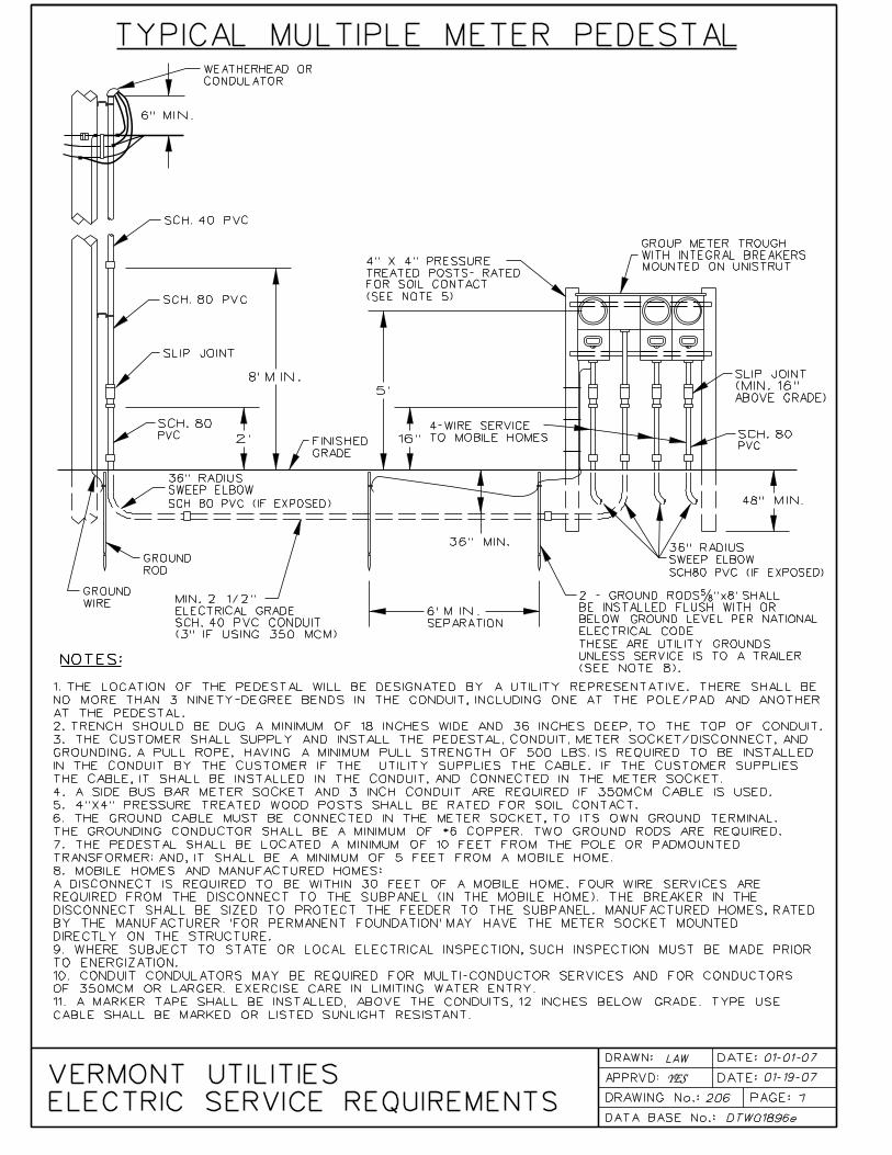


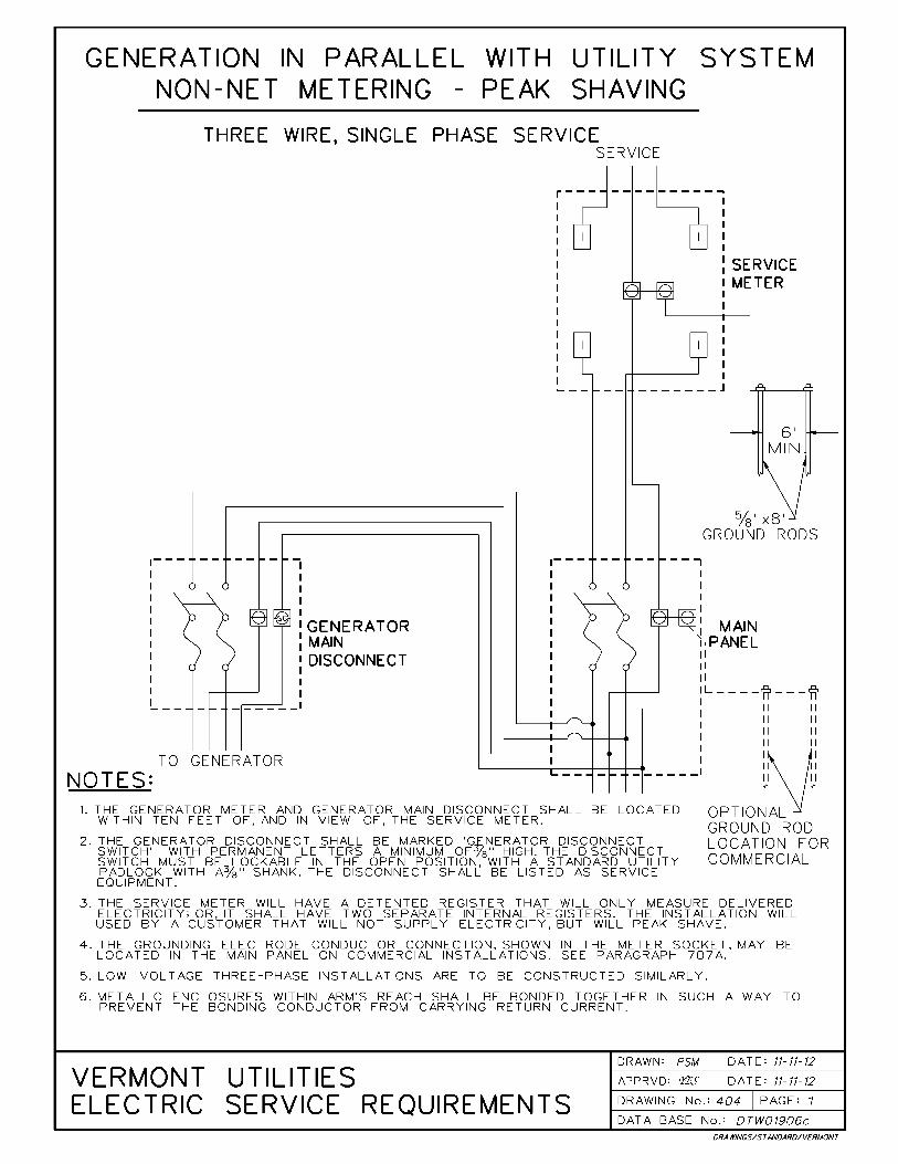

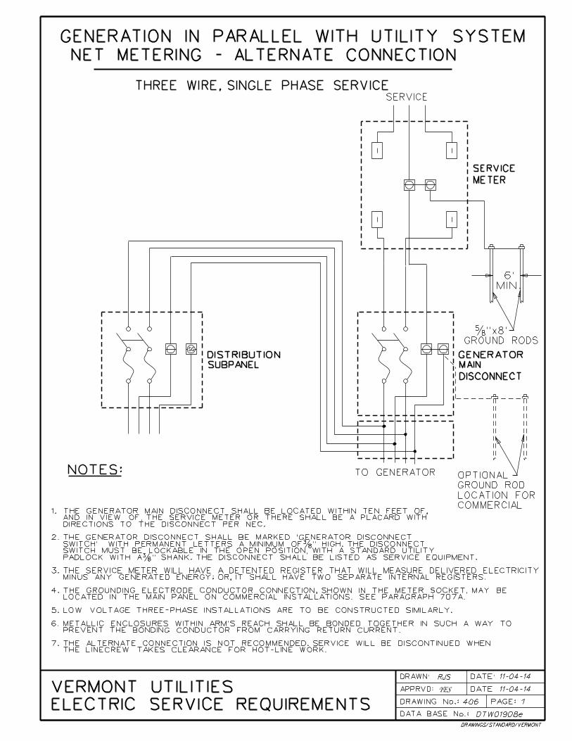
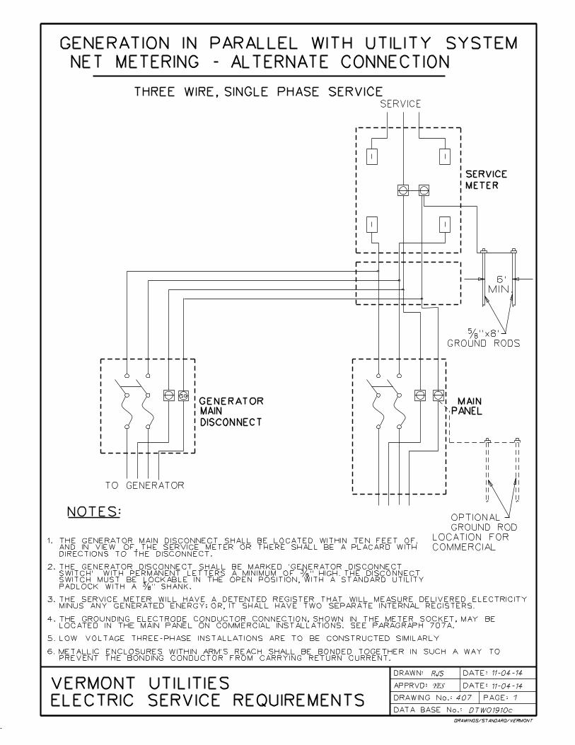


CUSTOMER LOAD DATA
CUSTOMER’S NAME ADDRESS TELEPHONE NO.
CONTRACTOR’S NAME ADDRESS TELEPHONE NO.
ELECTRICIAN’S NAME ADDRESS TELEPHONE NO.
LOCATION SERVICE ADDRESS
PROSPECTIVE NEW CUSTOMER__________________________________ PROSPECTIVE INCREASE LOAD
BUILDING INFORMATION
Building Use: __________ Expected Hours of Operation _________ Square Footage ___________ Shifts ____________SERVICE INFORMATION
Existing Service Amps______Volts_____Phase____WireSize__________Wire#Runs____ 3-Wire 4-Wire CUALService Desired Amps______Volts_____Phase ____WireSize__________Wire#Runs____ 3-Wire 4-Wire CUALDate Service Desired _______________ Number of Existing Meters _______________ Number of New Meters _____Size of Main Panel ____________________________ Amps Rate Classification___________________
Metering Requirements ________________________ Load Management? Yes No
Request Fault Current ? No Yes (Submit request form)CONNECTED LOADS
Existing New/Increase Existing New/Increase
Air Conditioning HP/TONS _____ _________ Motor Load HP ________ _________Cooking Equipment KW ______ _________Refrigeration KW ________ _________Heating Load KW ______ _________Storage Heat KW ________ _________Lighting Load KW ______ _________Water Heating KW ________ _________Receptacles KW ______ _________Special Equip. (Welder, X-Ray, Etc.) KW ________ _________Miscellaneous KW ______ _________Total Connected ______________ Estimated Demand __________________ KW------------------------------------------------------------------------------------------------------------------------------------------------
Emergency Generator No Yes Size _________________ Switch Type _________________________
List all individual motors over 5 HP (Circle those included above)_____________________________________________
______________________________________________________________________________________________________
(Single phase motors over 5 HP and three phase motors over 10 HP required reduced voltage starting) (Use back of sheet if necessary)
Miscellaneous Motors ____________________________________________________________________________This data will be used for transformer sizing and connected load billing information for this account. If loadchanges significantly, contact the District Office.Completed by ___________________________ Title _____________________________ Date ________________Accepted by _____________________________ Title _____________________________ Date ________________
(Utility Representative)
For Utility Use OnlyDistrict ________________________________ Town _________________________________Circuit _____________________ Line Name ___________________________ Pole/Pad Number ______________Present Demand ____________ Expected Increase ________________ Expected Total Demand _____________Transformer KVA Size_________ Metering Requirement_____________________________________________Estimated Annual Revenues ____________________From: ____________________________ Dept. _______________________________ Date ___________________
TO: ENGINEERING METERING DISTRICT SUPERINTENDENT ENERGY SERVICES
ENERGY PLANNING CUSTOMER SERVICES DISTRICT MANAGER
OTHER _____________________________________________________________________________
VERMONT UTILITIES ELECTRIC SERVICE REQUIREMENTS
Revised November, 2012 DRAWING #501

Requesting Party Name Address Phone # Business/Owner Address Phone # Service Location Address Rating of Service Entrance Equipment: __________________ Amperes ______________ Volts Number of Runs ________ Single Phase _______ Three Phase _______ Service Equipment is New _____ Existing ____ Secondary conductor size ___________ & type CU ________ AL ________ Secondary distance from transformer terminals ___________
For Utility Use Only
___________ A. Transformer secondary terminals ___________ B. Weatherhead ____________C. Pedestal, Meter, Utility Pole ___________ D. Other
_____________ Amperes at ___________ Volts line-line _____________ Amperes at ___________ Volts line neutral Values used in calculation: Transformer size ____________________ Va, single phase ______, three phase ______, Transformer impedance ______________ %, nominal secondary voltage _______________, Copies of this sheet sent to: ____________ Requester ____________ Owner of property ____________ Architect associated with project ____________ Consulting Engineer associated with project ____________ State Wire Inspector Form completed by: Name: _____________________________ Title: _______________________ Date: ____________
VERMONT UTILITIES ELECTRIC SERVICE REQUIREMENTS
Revised January, 2007 Drawing #502
FAULT CURRENT REQUEST
Location for which short circuit currents were calculated by
Value of SYMMETRICAL short circuit currents resulting from calculation:

METER SOCKET SPECIFICATION
VERMONT UTILITIES ELECTRIC
SERVICE REQUIREMENTS
App’d: YES DATE: 02/10 601pg1f.doc
DRAWING NUMBER 601 Page 1
Transformer-Rated Metering: The Utility shall supply all the necessary meter mounting devices for transformer-rated metering. Transformer-rated metering shall be used only when the Utility determines that self-contained metering is impractical, (see below). In all cases, the Utility shall specify the type of metering to be installed. Self-Contained Metering: Self-contained metering is standard where the service rating is not more than 200 amperes, and where on grounded systems, the line to ground voltage does not exceed 300 volts. In all cases, the Utility shall specify the type of metering that is to be installed. Class 320 ampere sockets may be allowed, (check with local Utility). The customer shall furnish and install a meter socket which meets the appropriate section(s) of this standard. For multiple socket installations, the Utility must be consulted to determine its requirements for these types of installations. A. Type of Services: 1. Overhead single phase, three wire 120/240 volt services a. Residential: The customer shall supply a socket meeting part B of this
standard, “General Socket Specifications”. Manual bypasses are required for 320 amp sockets and must meet Section C of this standard, “Manual Bypasses”.
b. Commercial and Industrial: The customer shall supply a socket with a
manual bypass, and terminal shields. The socket shall meet Sections B and C of this standard, “General Socket Specifications” and “Manual Bypasses”.
2. Overhead Single Phase Three Wire 120/208 Volt (Network) Services a. Residential: The customer shall supply a meter socket with a fifth terminal.
It shall meet Section B of this standard, “General Socket Specifications”. Manual bypasses are required for 320 amp sockets and must meet part C of this standard, “Manual Bypasses”.
b. Commercial and Industrial: The customer shall supply a meter socket with a
fifth terminal, a manual bypass, and terminal shields. The socket shall meet sections B and C of this standard, “General Socket Specifications” and “Manual Bypasses”.
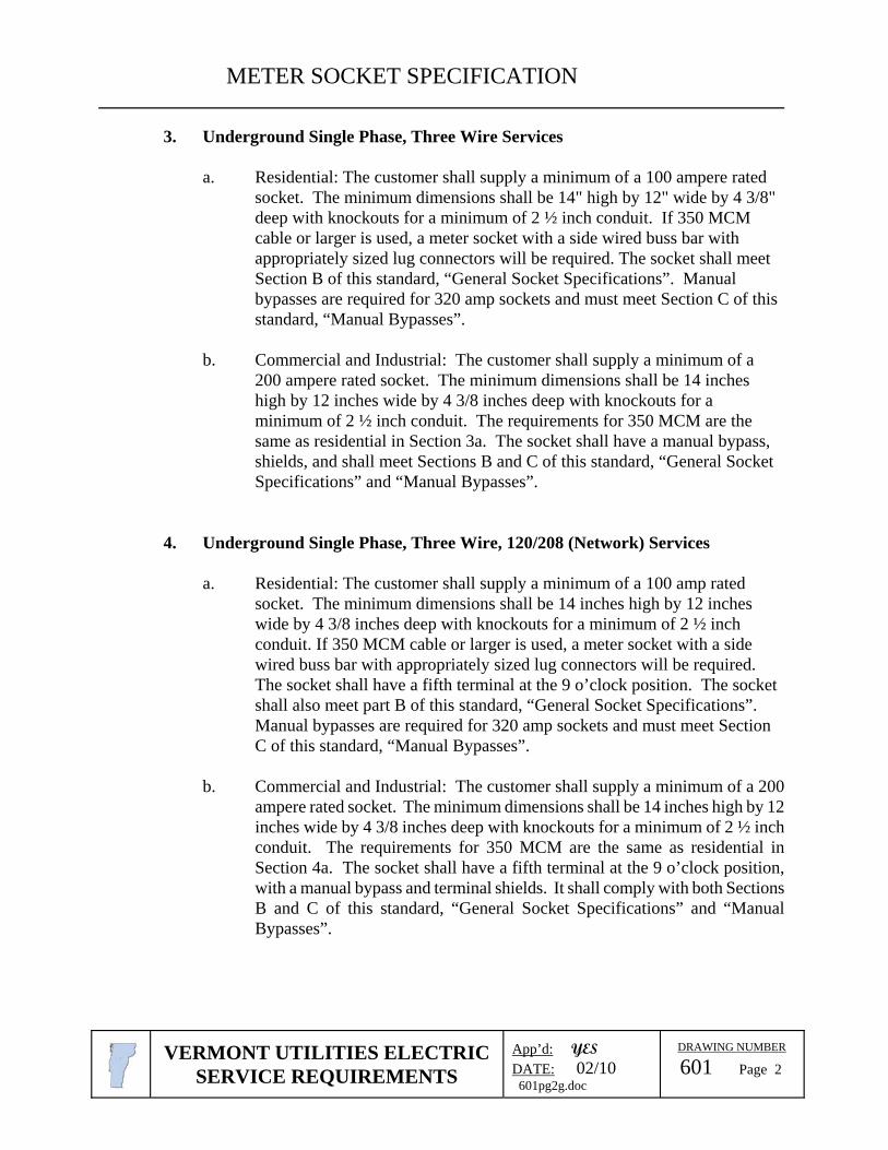
METER SOCKET SPECIFICATION
VERMONT UTILITIES ELECTRIC
SERVICE REQUIREMENTS
App’d: YES DATE: 02/10 601pg2g.doc
DRAWING NUMBER 601 Page 2
3. Underground Single Phase, Three Wire Services a. Residential: The customer shall supply a minimum of a 100 ampere rated
socket. The minimum dimensions shall be 14" high by 12" wide by 4 3/8" deep with knockouts for a minimum of 2 ½ inch conduit. If 350 MCM cable or larger is used, a meter socket with a side wired buss bar with appropriately sized lug connectors will be required. The socket shall meet Section B of this standard, “General Socket Specifications”. Manual bypasses are required for 320 amp sockets and must meet Section C of this standard, “Manual Bypasses”.
b. Commercial and Industrial: The customer shall supply a minimum of a
200 ampere rated socket. The minimum dimensions shall be 14 inches high by 12 inches wide by 4 3/8 inches deep with knockouts for a minimum of 2 ½ inch conduit. The requirements for 350 MCM are the same as residential in Section 3a. The socket shall have a manual bypass, shields, and shall meet Sections B and C of this standard, “General Socket Specifications” and “Manual Bypasses”.
4. Underground Single Phase, Three Wire, 120/208 (Network) Services a. Residential: The customer shall supply a minimum of a 100 amp rated
socket. The minimum dimensions shall be 14 inches high by 12 inches wide by 4 3/8 inches deep with knockouts for a minimum of 2 ½ inch conduit. If 350 MCM cable or larger is used, a meter socket with a side wired buss bar with appropriately sized lug connectors will be required. The socket shall have a fifth terminal at the 9 o’clock position. The socket shall also meet part B of this standard, “General Socket Specifications”. Manual bypasses are required for 320 amp sockets and must meet Section C of this standard, “Manual Bypasses”.
b. Commercial and Industrial: The customer shall supply a minimum of a 200
ampere rated socket. The minimum dimensions shall be 14 inches high by 12 inches wide by 4 3/8 inches deep with knockouts for a minimum of 2 ½ inch conduit. The requirements for 350 MCM are the same as residential in Section 4a. The socket shall have a fifth terminal at the 9 o’clock position, with a manual bypass and terminal shields. It shall comply with both Sections B and C of this standard, “General Socket Specifications” and “Manual Bypasses”.

METER SOCKET SPECIFICATION
VERMONT UTILITIES ELECTRIC
SERVICE REQUIREMENTS
App’d: YES DATE: 02/10 601pg3e.doc
DRAWING NUMBER 601 Page 3
5. Overhead Three Phase Services a. All Customers: The customer shall supply a 7-terminal meter socket for 3
phase 4 wire services, and a 5-terminal meter socket for 3 phase 3 wire services. The socket shall have a manual bypass and comply with Sections B and C of this standard, “General Socket Specifications” and “Manual Bypasses”. For multiple socket installations, the Utility must be consulted to determine the special requirements for this type of installation.
6. Underground Three Phase 3 and 4 Wire Services Only a. All Customers: The customer shall supply a minimum of a 200 ampere rated
socket. The line and load lugs shall be capable of accepting 350 MCM cu/al. The socket shall have a manual bypass and meet both Sections B and C of this standard, “General Socket Specifications” and “Manual Bypasses”.
B. General Socket Specifications: 1. Sockets shall be Listed and Approved for their location and use. 2. Sockets shall be of the rectangular sheet-metal type. Round-type sockets or cast-
metal sockets are not permitted. 3. The socket rating shall equal or exceed the capacity of the service entrance equipment
and conductors. 4. The socket lugs shall be sized appropriately to fit the required service conductor size.
The socket lugs shall be of the Lay-in type. A grounding electrode conductor connector, connected to the neutral bus, shall be included in sockets intended for use in residential applications.
5. Sockets may be the ring type or ringless. Sealing rings, if required, shall be supplied by the customer.
6. Automatic bypasses are not permitted under any circumstances. 7. There shall normally, not be more than 3 vertical positions at any multiple-socket
installations. 8. All sockets, at the time of installation, must be equipped with the number of terminals
required by the type of service to be metered. 9. All four terminal sockets shall have the capability of adding a fifth terminal in the (6
or 9 o’clock positions), without removing the terminal blocks. When an existing installation is changed to accommodate a different type of service or rate requiring additional terminals, the additional terminals must be furnished and installed by the customer at the time of the change or the socket replaced with a socket containing the proper number of terminals.
10. Cover plates shall be the approved clear plastic type. The Utility will supply them. They will be used after the wiring is completed to protect the interior until a meter is set.

METER SOCKET SPECIFICATION
VERMONT UTILITIES ELECTRIC
SERVICE REQUIREMENTS
App’d: YES DATE: 02/10 601pg4f.doc
DRAWING NUMBER 601 Page 4
11. Note carefully that on 120/240 volt, three phase, four wire, Delta services, the conductor that measures 208 volts-to-ground must be connected to the right hand terminals of the sockets.
12. On commercial and industrial services all meter sockets shall be equipped with manual by-passes and shields for meter jaws. See Drawings 602 and 603.
C. Manual Bypasses:
Manual by-passes are required on certain services in order to permit meter exchange without interruption of service to the customer, and as an additional safety feature for the meter person. By-passes are not designed for and must not be used as load making or breaking devices.
To be approved for system use, sockets with a manual by-pass must meet the following requirements:
1. Automatic bypasses are prohibited. 2. Bypass shall have a single, independent, Bypass handle-operated mechanism. 3. The non-bypassed, in service position of the operating mechanism must be visible
when the meter is installed without the socket cover for test purposes. 4. It must not be possible to replace the socket cover when the operating mechanism
handle is in the bypassed position. 5. By-passes which require auxiliary equipment, such as straps, jumpers, etc., shall
not be allowed. 6. All three phase sockets with bypasses must have a mechanism which locks the meter
blades in the socket jaws when in the non-bypassed (in service) position, and which will release the blades in the bypassed position.


