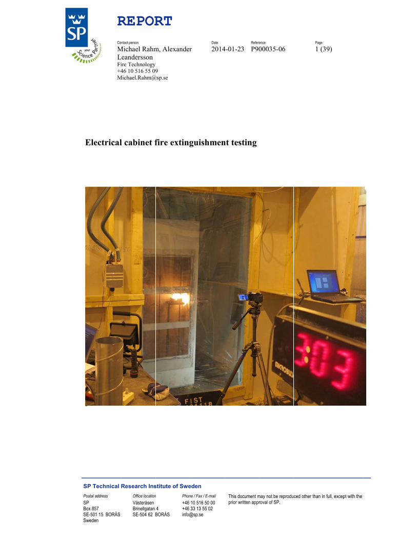
electrical cabinet fire extinguishment testing
TRANSCRIPT

Electrical cabinet fire extinguishment testing
CSA: John A. Hiltz DRDC – Atlantic Research Centre
Prepared by: Michael Rahm, Alexander Leandersson Fire Technology Box 857 SE-501 15 BORÅS Sweden
PWGSC Contract Number: W7707-145703;11gh/11gg
The scientific or technical validity of this Contract Report is entirely the responsibility of the Contractor and the contents do not necessarily have the approval or endorsement of Defence R&D Canada.
Defence Research and Development Canada Contract Report DRDC-RDDC-2014-C181 December 2014
© Her Majesty the Queen as represented by the Minister of National Defence, 2014
© Sa Majesté la Reine, représentée par le ministre de la Défense nationale, 2014
E
SPoSPBoSESw
RCo
MLFi+4M
Electrical
SP Technical ostal address P ox 857 E-501 15 BORÅS weden
REPORntact person
Michael RahmLeandersson
ire Technology 46 10 516 55 09
Michael.Rahm@
l cabinet f
Research InsOffice locationVästeråsen Brinellgatan SE-504 62 B
RT
m, Alexander
9 @sp.se
fire exting
stitute of Swen Phon
4 BORÅS
+46 +46 info@
Date
r 2014
guishmen
eden ne / Fax / E-mail 10 516 50 00 33 13 55 02
@sp.se
Refere
4-01-23 P90
nt testing
This document mprior written appr
ence
00035-06
may not be reproduroval of SP.
Page
1 (39
ced other than in fu
9)
ull, except with the
S
A
TlCnNsSma
R
SP Technical
Abstract
The FiST-prolateral (CanaCooperative navy ships. ANOVEC1230suppressing fSP Technicalmonitored thand cooling o
REPORT
Research Ins
oject “New Tada, the NethScience and As part of th0, nitrogen, afires and prevl Research Ine toxicity anof the space.
stitute of Swe
Technologieserlands, SweTechnology
his collaboratand carbon dventing re-ignstitute of Swnd corrosivity
The report
Date
2014
eden
s for Fire Supeden) researy MOU. The tive project, dioxide, weregnition in an weden, Borasy of degradatpresents and
Refere
4-01-23 P90
ppression Onch project unfocus of the three gaseou
e evaluated toelectrical cas, Sweden intion products
d discusses th
ence
00035-06
n Board Navnder the CANproject is ac
us fire suppreo determine tabinet. The tn November/Ds arising fromhe results of t
Page
2 (39
val Craft”, is N/NLD/SWEctive fire fighession agentstheir efficacyesting, carrieDecember 20m the supprethe testing.
9)
a tri- E hting on s, y in ed out at 013, also ssants

S
TA
T
I
T
I
F
T
P
T
R
C
R
R
SP Technical
Table of cAbstract .......
Table of cont
Introduction .
Test compart
Instrumentati
Fire scenario
Test equipme
Performance
Test program
Results .........
Extinguish
Toxicity –
Analysi
Decay o
Temperatu
Detection
Corrosion .
Compar
Cabinet pr
Oxygen co
CO2 exting
Conclusions
References ...
REPORT
Research Ins
contents ....................
tents ............
....................
tment ...........
ion ..............
os .................
ent ...............
indicators ..
mme .............
....................
hment ..........
– HF concent
s of low mea
of HF ...........
ures ..............
time ............
....................
rison to outdo
ressure .........
oncentration
guishment in
and commen
....................
stitute of Swe
....................
....................
....................
....................
....................
....................
....................
....................
....................
....................
....................
trations .........
asured HF le
....................
....................
....................
....................
oor environm
....................
....................
n a decommis
nts ................
....................
Date
2014
eden
....................
....................
....................
....................
....................
....................
....................
....................
....................
....................
....................
....................
vels with FT
....................
....................
....................
....................
ment accordin
....................
....................
ssioned elect
....................
....................
Refere
4-01-23 P90
....................
....................
....................
....................
....................
....................
....................
....................
....................
....................
....................
....................
TIR method ..
....................
....................
....................
....................
ng to ISO 92
....................
....................
trical cabinet
....................
....................
ence
00035-06
....................
....................
....................
....................
....................
....................
....................
....................
....................
....................
....................
....................
....................
....................
....................
....................
....................
223 ..............
....................
....................
t from a navy
....................
....................
Page
3 (39
....................
....................
....................
....................
....................
....................
....................
....................
....................
....................
....................
....................
....................
....................
....................
....................
....................
....................
....................
....................
y ship...........
....................
....................
9)
............ 2
............ 3
............ 4
............ 5
............ 6
............ 7
............ 7
.......... 12
.......... 12
.......... 13
.......... 13
.......... 15
.......... 19
.......... 22
.......... 23
.......... 26
.......... 27
.......... 29
.......... 30
.......... 32
.......... 33
.......... 37
.......... 39
S
IAIgpc
Tsc
TTw
T
A
R
SP Technical
IntroductA series of fiInstitute of Sgaseous fire sprotection agcapacity.
The extinguisystem and aconnected to
The tests werThe cabinet wwere collecte
Two differen
A 5 kabilit
An efuel s(cablexter
An aspirating
REPORT
Research Ins
tion ire extinguishweden durinsuppressants
gainst re-igni
shment systea system of p
the cabinet t
re performedwas positioneed and subseq
nt fire scenari
kW heptane ty to extingu
external radiasource contale sheathing)rnal power fr
g fire detecto
stitute of Swe
hment tests ing Novembers/extinguishmition, toxicity
ems evaluateortable CO2to allow disc
d in a cabineted in an air tquently analy
ios where ev
fire to represuish a fast groation panel apaining a cable) is slowly herom the elect
or was used i
Date
2014
eden
in electrical cr 2013. The gment systemsy and corrosi
ed were a fixeextinguisher
charge of CO
t with the dimtight room wysed.
valuated;
sent a fast growing fire bepplying a thee bundle to reated until it trical failure.
in all tests.
Refere
4-01-23 P90
cabinets weregoal of the tes with regardivity of degra
ed NOVEC rs with a NA
O2 in the cabi
mensions 1.6where any gas
rowing fire. Tefore severe ermal flux ofrepresent a ty
ignites and t.
ence
00035-06
e run at SP Test series wads to extinguiadation prod
1230 systemATO couplinginet without o
6 m x 0.4 m xses escaping
This scenariodamage occuf approximatypical short cthe fire is con
Page
4 (39
Technical Res to evaluateishment effic
ducts, and coo
m, a fixed nitrg that can be opening the
x 2.0 m (L x from the cab
o tested the surred tely 40 kW/mcircuit fire. Tntinuously fe
9)
esearch e three ciency, oling
rogen
door.
W x H). binet
system’s
m2 to the The fuel fed with
S
TT0wsw
T4tst
Tpctv
F
F
R
SP Technical
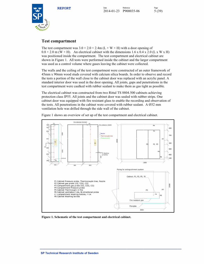
Test compThe test com0.8 × 2.0 m (was positioneshown in Figwas used as a
The walls an45mm x 90mthe tests a postandard intetest compartm
The electricaprotection clacabinet door the tests. All ventilation ho
Figure 1 show
Figure 1. Sch
REPORT
Research Ins
partment mpartment wa(W × H). Aned inside the
gure 1. All tea control vol
d the ceilingmm wood stuortion of the wrior door wament were ca
al cabinet waass IP55. Allwas equippepenetrations
ole was drille
ws an overvi
ematic of the
stitute of Swe
as 3.0 × 2.0 ×n electrical c
e compartmenests were perume where g
g of the test cds covered wwall close to
as used in theaulked with r
s constructedl joints and thed with fire rs in the cabined through th
iew of set up
e test compar
Date
2014
eden
× 2.4m (L × Wcabinet with nt. The test rformed insidgases leaving
ompartment with calcium o the cabinet e door openinrubber sealan
d from two Rhe cabinet do
resistant glasnet were covehe side wall
p of the test c
rtment and el
Refere
4-01-23 P90
W × H) withthe dimensiocompartmende the cabineg the cabinet
were construsilica boarddoor was repng. All jointsnt to make th
Rittal TS 880oor was seales to enable thered with rubof the cabine
compartment
ectrical cabin
ence
00035-06
h a door openons 1.6 x 0.4 nt and electricet and the larwere collect
ucted of an os. In order toplaced with as, gaps and phem as gas ti
04.500 cabineed with rubbhe recordingbber sealant. et.
t and electric
net.
Page
5 (39
ning of x 2.0 (L x W
cal cabinet arger compartmted.
outer framewo observe andan acrylic papenetrations ight as possib
ets achievingber strips. Ong and observa A Ø32 mm
al cabinet.
9)
W x H) are ment
work of d record
anel. A in the ble.
g ne ation of
m

S
ITpi
Ppp
Pcec
P
Pr
Pv
Pppsc
R
SP Technical
InstrumenThe test comprobes, pressin Figure 1. T
P1: A thermopositioned 10placed 100 m
P2-P3: Oxygcompartmenteach measuricabinet and c
P4: Pressure
P5: A shielderegister extin
P6: Bi-directventilation ho
P7-P8: Gas sposition P7 gposition P8 gsampling wacompartment
REPORT
Research Ins
ntation mpartment andsure probes, aThe instrume
ocouple tree 00, 250, 500,
mm below the
gen, carbon mt (P3) and caing position fcompartment
probe placed
ed 1 mm thenguishment a
tional probe ole (Ø 32 mm
sampling witgas from the gas from the s to measuret.
stitute of Swe
d electrical cand bi-directentation at ea
with 0.5 mm, 1000 and 1e ceiling in th
monoxide anabinet (P2). Afor analysis.t.
d 100 mm be
rmocouple pand re-ignitio
with one 0.5m). Flow out
th wash bottlcompartmencabinet was
e hydrogen fl
Date
2014
eden
cabinet were tional probesach position i
m type K ther1750 mm belhe cabinet.
nd carbon dioApproximate
The probes
elow the ceil
placed just aon times.
5 mm type K t of the cabin
les (0.6 l/minnt was samplesampled wit
luoride and h
Refere
4-01-23 P90
equipped wis. The measuis described
rmocouples. low the ceilin
oxide measurely 5 l gas perwere placed
ling of the co
above the fue
thermocoupnet was meas
n) and FTIR ed with bothth wash bottlhydrogen chl
ence
00035-06
ith thermocouring positionin detail belo
The thermocng. The pres
ring probes inr minute was1000 mm ab
ompartment.
el surface or c
ple placed in sured as posi
spectrometeh wash bottleles. The objeloride in the c
Page
6 (39
ouples, gas mns (P1-P8) arow.
couples weresure probe w
nside the s pumped oubove the floo
cable surface
the cabinet itive flow.
r (3 l/min). Is and FTIR. ctive of gas cabinet and t
9)
measuring re shown
e was
ut from or in
e to
In In
the
S
FTStpwt
Fm
TF
Fccfoht
I
W
T(phth
Tl
R
SP Technical
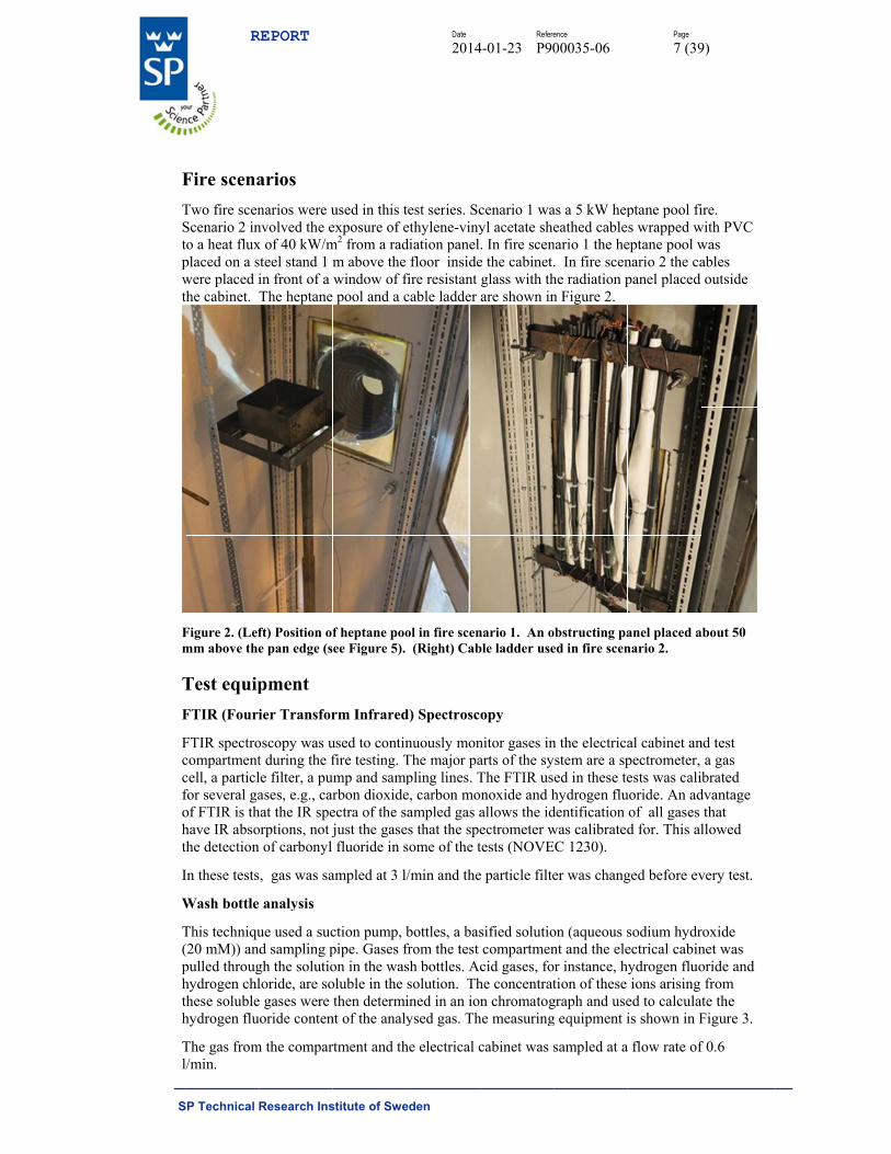
Fire scenaTwo fire scenScenario 2 into a heat fluxplaced on a swere placed ithe cabinet.
Figure 2. (Lefmm above the
Test equipFTIR (Fouri
FTIR spectrocompartmentcell, a particlfor several gaof FTIR is thhave IR absothe detection
In these tests
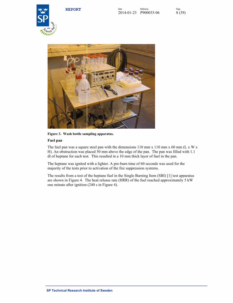
Wash bottle
This techniqu(20 mM)) anpulled throughydrogen chlthese solublehydrogen flu
The gas froml/min.
REPORT
Research Ins
arios narios were unvolved the ex of 40 kW/msteel stand 1 min front of a The heptane
ft) Position ofe pan edge (s
pment ier Transfor
oscopy was ut during the fle filter, a puases, e.g., car
hat the IR speorptions, not jn of carbonyl
, gas was sa
analysis
ue used a sucd sampling p
gh the solutioloride, are soe gases were uoride conten
m the compar
stitute of Swe
used in this texposure of em2 from a radm above the window of f pool and a c
f heptane pooee Figure 5).
rm Infrared
used to continfire testing. T
ump and samprbon dioxideectra of the sjust the gasefluoride in s
ampled at 3 l/
ction pump, bpipe. Gases fon in the wasoluble in the then determi
nt of the analy
rtment and th
Date
2014
eden
test series. Scethylene-vinydiation panel
floor insidefire resistant cable ladder
ol in fire scen (Right) Cab
d) Spectrosc
nuously monThe major papling lines. Te, carbon moampled gas a
es that the spesome of the t
/min and the
bottles, a basfrom the test sh bottles. Acsolution. Thined in an ionysed gas. Th
he electrical c
Refere
4-01-23 P90
cenario 1 wayl acetate she. In fire scene the cabinet.glass with thare shown in
nario 1. An oble ladder use
opy
nitor gases inarts of the syThe FTIR usonoxide and hallows the idectrometer wtests (NOVE
e particle filte
sified solutiocompartmencid gases, fo
he concentratn chromatog
he measuring
cabinet was s
ence
00035-06
as a 5 kW hepeathed cable
nario 1 the he. In fire scenhe radiation pn Figure 2.
obstructing paed in fire scen
n the electricastem are a sped in these tehydrogen fludentification was calibratedEC 1230).
er was chang
on (aqueous snt and the eleor instance, htion of these
graph and useg equipment i
sampled at a
Page
7 (39
ptane pool fis wrapped w
eptane pool wnario 2 the capanel placed
anel placed anario 2.
al cabinet anpectrometer, ests was cali
uoride. An adof all gases d for. This al
ged before ev
sodium hydrectrical cabin
hydrogen fluoions arising
ed to calculais shown in F
a flow rate of
9)
ire. with PVC was ables outside
about 50
nd test a gas brated
dvantage that llowed
very test.
roxide net was oride and from
ate the Figure 3.
f 0.6
S
F
F
THd
Tm
Tao
R
SP Technical
Figure 3. Wa
Fuel pan
The fuel pan H). An obstrudl of heptane
The heptane majority of th
The results frare shown in one minute a
REPORT
Research Ins
ash bottle sam
was a squareuction was p
e for each tes
was ignited whe tests prior
rom a test of Figure 4. T
after ignition
stitute of Swe
mpling appar
e steel pan wplaced 50 mmst. This resul
with a lighter to activation
f the heptane The heat relea
(240 s in Fig
Date
2014
eden
ratus.
with the dimem above the elted in a 10 m
er. A pre-burnn of the fire
fuel in the Sase rate (HRRgure 4).
Refere
4-01-23 P90
ensions 110 medge of the pmm thick lay
n time of 60 suppression
Single BurninR) of the fue
ence
00035-06
mm x 110 mpan. The panyer of fuel in
seconds wassystems.
ng Item (SBIel reached ap
Page
8 (39
m x 60 mm (n was filled w
the pan.
s used for the
I) [1] test apppproximately
9)
(L x W x with 1.1
e
paratus 5 kW

S
Fr
Fa
R
Ttoa
R
SP Technical
Figure 4 – Merig.
Figure 5. (Lefapproximatel
Radiation pa
The radiationtruncated conof the radiatiapplied volta
REPORT
Research Ins
easured HRR
ft) Heptane fily 50 mm abo
anel
n panel consine. When theon (thermal
age.
stitute of Swe
R as a functio
fire in test 16.ove pan edge.
isted of an ele cone is powflux) depend
Date
2014
eden
on of time fro
. (Right) Pictu
.
lectrical heatwered it irradds on the tem
Refere
4-01-23 P90
m test using
ure of the fue
ter rod tightlydiates the ma
mperature of t
ence
00035-06
the heptane p
el pan with ob
y wound intoaterial in fronthe heater ro
Page
9 (39
pan in the SB
bstructing pa
o the shape ont of it.. The d, hence on t
9)
BI test
anel
of a intensity
the
S
TTta
N
IenF
F
T
Tic
D
AiwoaTt%rt
E
TNa
R
SP Technical
The thermal The plate thethe fire resistapproximatel
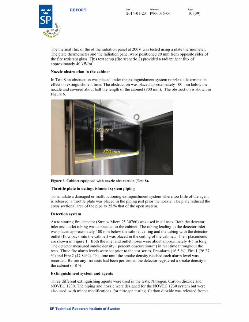
Nozzle obstr
In Test 8 an oeffect on extinozzle and coFigure 6.
Figure 6. Cab
Throttle pla
To simulate ais released, across section
Detection sy
An aspiratinginlet and outlwas placed apoutlet (flow bare shown in The detector tests. Three f%) and Fire 2recorded. Bethe cabinet o
Extinguishm
Three differeNOVEC 123also used, wi
REPORT
Research Ins
flux of the oermometer antant glass. Thly 40 kW/m2
ruction in th
obstruction winguishment overed about
binet equippe
te in extingu
a damaged oa throttle platnal area of the
ystem
g fire detectolet tubing wapproximatelyback into theFigure 1. Bmeasured sm
fire alarm lev2 (47.84%). Tfore any firef 8 %.
ment system
ent extinguish0. The pipin
ith minor mo
stitute of Swe
f the radiationd the radiatihis test setup2.
he cabinet
was placed utime. The ob
t half the len
ed with nozzle
uishment sy
or malfunctiote was placede pipe to 25 %
or (Stratos Mas connectedy 100 mm be
e cabinet) waBoth the inletmoke densityvels were setThe time unt
e tests had be
and agents
hing agents wng and nozzleodifications, f
Date
2014
eden
on panel at 2ion panel we
p (fire scenari
under the extibstruction wa
ngth of the ca
e obstruction
ystem piping
oning extingud in the pipin% that of the
Micra 25 3076d to the cabinelow the cabas placed in tt and outlet hy ( percent obt prior to the til the smoke
een performe
were used ine were designfor nitrogen
Refere
4-01-23 P90
00V was testere positionedio 2) provide
inguishment as placed app
abinet (800 m
n (Test 8).
g
uishment sysng just prior te open system
60) was usednet. The tubininet ceiling a
the ceiling ofhoses were abbscuration/mtest series, P
e density reacd the detecto
n the tests, Nined for the Ntesting. Carb
ence
00035-06
ted using a pd 20 mm froed a radiant h
system nozzproximately
mm). The ob
tem where tothe nozzle. Tm.
d in all tests. Bng leading toand the tubinf the cabinet.bout approxi
m) in real timPre-alarm (16ched each alaor registered
itrogen, CarbNOVEC 1230bon dioxide w
Page
10 (3
plate thermomm opposite sheat flux of
zle to determ100 mm bel
bstruction is s
oo little of thThe plate redu
Both the deto the detectorng with the d. Their placemately 4-5 me throughout
6.5 %), Fire 1arm level waa smoke den
bon dioxide a0 system butwas released
39)
meter. sides of
mine its low the shown in
he agent uced the
ector r inlet
detector ements m long. t the 1 (26.27 as nsity in
and t were d from a

S
hw
F(
NpaTwg
Ccf
Nsbr
R
SP Technical
hand held COwall in Figur
Figure 7. (Lef(Right) NOVE
NOVEC 123piping. Two agent necessaThe nozzle wwith larger orgas concentra
Carbon dioxicoupling. Thfully opened
Nitrogen: Thsecond nozzbar, nitrogen released at th
REPORT
Research Ins
O2 extinguishre 11.
ft) Hand heldEC 1230 (180
0: The systenozzles wereary to achiev
with smaller orifice outsideation was 5.9
ide: The systhe inlet sockat the time o
he NOVEC 1zle, outside th
cylinder withe pressure o
stitute of Swe
her through a
d CO2 extingu0º) nozzle use
m consisted e used becauve the effectiorifice (see Fe the test com91 %.
tem consistedket and hand of release and
230 cabinethe test compath reducing v
of 12.5 bar fo
Date
2014
eden
a NATO cou
uisher (2 kg) ed for all NOV
of one storaguse the storagve concentra
Figure 7) wasmpartment. T
d of a 2 kg happlicator ard the release
piping and nartment was valve was theor 60 s.
Refere
4-01-23 P90
upling. The c
connected to VEC 1230 an
ge cylinder (ge cylinder cation to supps placed insiThe release t
and held COre shown in F time was ap
nozzle was uplugged for
e source of th
ence
00035-06
coupling is s
cabinet thro
nd nitrogen fi
(5 L, 3kg), twontained abo
press fires in de the cabinetime was 4 s
O2 extinguisheFigure 7. Th
pproximately
sed for the nthese tests.
he nitrogen g
Page
11 (3
shown in the
ugh NATO cire suppressio
wo nozzles anout three timethe electricaet and the noand the calc
er and a NAThe extinguishy 50 – 60 s.
nitrogen testinA 20 l and 5
gas. Nitroge
39)
cabinet
coupling. on tests.
nd es the l cabinet.
ozzle culated
TO her was
ng. The 50 l, 250 en was
S
PTe
Ect
P
Tfufsc
Tc
Cwmt
Dd
TTp
TT
247891111111
R
SP Technical
PerformaThe followinextinguishme
Extinguishmcan reduce thtimes were v
Pressure: Cab
Toxic producfrom the comused NOVECfrom both thesolution. Theconcentration
Temperaturecool the gase
Corrosion: Dwere exposedmeasured andthe cabinet.
Detection timdetection tim
Test progThe tests carrpresented in t
Table 1 – TesTest no. S
2 H4 H7 C8 H9 H10 C11 H12 C13 C16 H18 C19 C
REPORT
Research Ins
ance indicng performanent system to
ent/re-ignitiohe damage caerified visua
binet and com
ct release: A mpartment, prC 1230 as thee compartmee water sampns of acid ga
s: Thermocoes in the cabi
During each od to the atmod this mass l
me: An aspirame for the diff
gramme ried out in ththis report, h
st programmeScenario
Heptane Heptane Cable Heptane Heptane Cable Heptane Cable Cable Heptane Cable Cable
stitute of Swe
cators nce indicatorso be installed
on time: Fastaused to the eally.
mpartment p
FTIR spectrrimarily hyde extinguishient and the caples were anaases (hydroge
ouples were pnet.
of the extinguosphere in thoss was take
ating fire detfferent fire an
his study are hence the mis
e Ext. system
Free burniNovec 123Novec 123Novec 123CO2 CO2 Novec 123Novec 123Novec 123N2
N2 Novec 123
Date
2014
eden
s was identifd in electrical
t extinguishmequipment in
pressure was
rometer wasdrogen fluoriing agent. Inabinet in gasalysed in an ien fluoride/h
placed in the
uishment teste electrical c
en as a measu
tector (Stratond gaseous fi
listed in Tabssing test num
m Relatihumid
ing Not re30 35 30 5630 31
41 56
30 37 30 80 30 39
3131
30 42
Refere
4-01-23 P90
fied as imporl cabinets.
ment and goon the cabinet
monitored d
used to analyides (HF) reln addition, sms wash bottleion chromato
hydrogen chlo
cabinet to ev
ts metallic cocabinet. Massure of the cor
os Micra 25 3ire suppressio
ble 1. The resmbers in the
ve dity [%]
C
corded
InO
SIn
N
ence
00035-06
rtant in the se
od protectiont. Extinguishm
during each te
yse smoke/dleased duringmoke and gaes filled with ograph to detoride).
valuate the s
oupons (copps loss of the rrosivity of
30760) was uon scenarios
sults of failed table.
Comment
ncreased humObstructed no
Slow floodingncreased hum
No ventilatio
Page
12 (3
election of an
n against re-iment/re-igni
est.
ecompositiong the fire testses were sama sodium hy
termine the
system’s capa
per, zinc andcoupons wasthe environm
used to meas.
d tests are no
midity ozzle
g midity
n opening
39)
n
gnition tion
n gases ts that mpled ydroxide
acity to
d steel) s ment in
sure
ot
S
R
E
Ts
TTn
47891111111
Tbscatswa
R(wfwt
Tisbc
Fseci
Om
R
SP Technical
Results
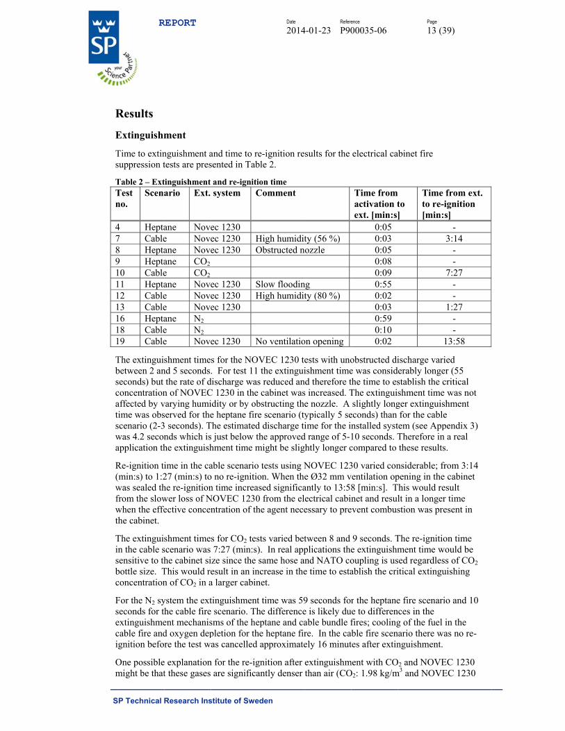
Extinguishm
Time to extinsuppression t
Table 2 – ExtTest no.
Scena
4 Hepta7 Cable8 Hepta9 Hepta10 Cable11 Hepta12 Cable13 Cable16 Hepta18 Cable19 Cable
The extinguibetween 2 anseconds) but concentrationaffected by vtime was obsscenario (2-3was 4.2 seconapplication th
Re-ignition ti(min:s) to 1:2was sealed thfrom the slowwhen the effethe cabinet.
The extinguiin the cable ssensitive to thbottle size. Tconcentration
For the N2 syseconds for thextinguishmecable fire andignition befo
One possiblemight be that
REPORT
Research Ins
ment
nguishment atests are pres
tinguishment ario Ext.
ane Novee Noveane Noveane CO2 e CO2 ane Novee Novee Noveane N2 e N2 e Nove
shment timend 5 seconds.
the rate of dn of NOVECvarying humiserved for the3 seconds). Tnds which ishe extinguish
ime in the ca27 (min:s) tohe re-ignitionwer loss of Nective concen
shment timescenario was he cabinet siThis would ren of CO2 in a
ystem the exthe cable fireent mechanisd oxygen depre the test w
e explanationt these gases
stitute of Swe
and time to rsented in Tab
and re-ignitisystem C
ec 1230 ec 1230 Hec 1230 O
ec 1230 Sec 1230 Hec 1230
ec 1230 N
s for the NO. For test 11
discharge wasC 1230 in theidity or by obe heptane fir
The estimateds just below thment time m
able scenarioo no re-ignition time increa
NOVEC 1230ntration of th
s for CO2 tes7:27 (min:s)
ize since the esult in an ina larger cabin
tinguishmente scenario. Thsms of the hepletion for thas cancelled
n for the re-igare significa
Date
2014
eden
e-ignition reble 2.
ion time Comment
High humiditObstructed n
Slow floodinHigh humidit
No ventilatio
OVEC 1230 te the extinguis reduced an
e cabinet wasbstructing thee scenario (tyd discharge tithe approvedmight be slig
o tests using Non. When the
ased significa0 from the elhe agent nece
sts varied bet). In real appsame hose a
ncrease in thenet.
t time was 59he differenceeptane and cahe heptane fir
approximate
gnition after antly denser
Refere
4-01-23 P90
sults for the
ty (56 %) nozzle
ng ty (80 %)
on opening
ests with unoishment time
nd therefore ts increased. Te nozzle. Aypically 5 seime for the in
d range of 5-1ghtly longer c
NOVEC 123e Ø32 mm vantly to 13:58ectrical cabinessary to pre
tween 8 and plications thend NATO coe time to esta
9 seconds fore is likely duable bundle fre. In the caely 16 minut
extinguishmthan air (CO
ence
00035-06
electrical ca
Time from activation text. [min:s]
0:05 0:03 0:05 0:08 0:09 0:55 0:02 0:03 0:59 0:10 0:02
obstructed die was considthe time to esThe extinguislightly long
econds) than nstalled syst10 seconds. Tcompared to
30 varied conventilation op8 [min:s]. Tnet and resul
event combus
9 seconds. Te extinguishmoupling is usablish the cri
r the heptaneue to differenfires; coolingble fire scen
tes after extin
ment with COO2: 1.98 kg/m
Page
13 (3
abinet fire
to ]
Time to re-i[min:s
1
ischarge varierably longestablish the cshment time ger extinguisfor the cable
tem (see AppTherefore in these results
nsiderable; frpening in the This would re
lt in a longerstion was pre
The re-ignitioment time wsed regardlesitical extingu
e fire scenarices in the g of the fuel ario there wanguishment.
O2 and NOVEm3 and NOVE
39)
from ext. ignition s]
- 3:14
- -
7:27 - -
1:27 - -
13:58
ied er (55 critical
was not shment e pendix 3)
a real s.
rom 3:14 cabinet
esult r time esent in
on time ould be s of CO2
uishing
io and 10
in the as no re-
EC 1230 EC 1230
S
1fg
R
SP Technical
13.6 kg/m3) afires where pgaseous agen
REPORT
Research Ins
and would acpositioned at nts at that lev
stitute of Swe
ccumulate (s1 m above th
vel would dec
Date
2014
eden
ettle with timhe floor of thcrease to the
Refere
4-01-23 P90
me) in bottomhe cabinet, the point where
ence
00035-06
m of the electhe critical coe re-ignition w
Page
14 (3
trical cabinencentration owas possible
39)
t. As the of these e.

S
T
HmaTdtft
Bf
V
M
V
TT
*Io
R
SP Technical
Toxicity – H
Hydrogen flumeasured usiaqueous sodiThe amount oduring the sathe wash watfluorides foutotal amount
Based on thefor each samp
.
is the m
Vm is the mo
MHF is the m
is the m
Vsamp is the s
Table 3 – MeaTest no.
Scenario
Heptane 4
Cable
56 % RH7 Heptane
Obstr. nozzle
8 Heptane
Slow flooding
11 Cable
80 % RH12
Cable 13
*In test 11 a It is, hence, roriginates fro
REPORT
Research Ins
HF concent
uoride (HF) ting two diffeium hydroxidof fluorides f
ampling perioter was colle
und in the samof fluorides
e fluoride mapling period
∗
∗∗
mass of fluori
lar volume o
olar mass of
molar mass of
ampled gas v
asured HF coo Sampling pe
4:30 – 9:310:48 – 1517:30 – 22
H
12:30 – 1723:00 – 2838:00 – 43
3:26 – 8:210:00 – 1516:30 – 21
4:00 – 9:011:30 – 1626:30 – 31
H
13:44 – 1823:44 – 2838:44 – 4310:18 – 1520:18 – 2536:00 – 41
significant areasonable toom COF2.
stitute of Swe
trations
testing was cerent methodde solution afound in the ods are showcted and the
mpling lines collected in
ass found in twas calculat
des found in
of an ideal ga
f HF
f F-
volume; 5 m
oncentrationseriods Fluorid
wasbottlcabin
[mg30 2.1
5:48 1.02:30 0.977:30 0.318:00 3.43:00 0.7126 1.7
5:00 0.681:30 0.4000 31
6:30 181:30 7.68:44 0.398:44 0.173:44 0.185:18 0.595:18 5.21:00 1.2
amount of Cao assume that
Date
2014
eden
carried out fods; wash bottland by FTIR
bottles and twn in Table 3
amount of flare presentedthe wash bo
the wash bottted accordin
(1) w
n washing bo
as, 24.8 l/mo
minutes of 0.6
s de in h le, net g]
Fluoridewash
bottleroom [m
0.0720 0.0317 0.0261 0.044
4 0.0671 0.040
7 0.0818 0.0420 0.023
0.140.31
6 0.139 0.0197 0.0268 0.0239 0.029
2 0.152 0.11
arbonyl fluort a significan
Refere
4-01-23 P90
or the NOVEles where flu(Fourier Trathe calculate. Further, the
fluorides dissd as a mass ottles.
tles the HF cgly:
where;
ttles
l at 25°C and
6 l/min is 3 l.
e in
e, mg]
Calc. HF conc.
cabinet [PPM]
2 975 472
6 443 4 144 7 1554 0 326 761
2 313 184
14047* 8385* 3468*
9 176 6 76 80
9 268 2387 557
ride (COF2) wnt portion of
ence
00035-06
EC 1230 testsuorides are dansform Infrad average HFe sampling lisolved were aof HF and as
concentration
d 1 atm.
Calc. HF conc. room
[PPM]
33 14 12 20 31 18 37 19 11 66*
144* 60* 9 12 10 13 70 50
was found inthe fluorides
Page
15 (3
s. HF levels wissolved in aared SpectrosF concentratines were waanalysed. Ths a percentag
n in the samp
HF in samplinglines cabinet
/percentage of total HF
collected [mg]
0.25 / 6%
0.53 = 12%
0.082 = 3%
1.3 = 2%
0.33 = 46%
3.0 = 42%
n the FTIR ans in the wash
39)
were an scopy). tions ashed, he ge of the
pled gas
g
f
HF in samplines roo
/percentagtotal HF
collected [m -
0.01 = 9%
0.004 = 3
0.015 = 2
0.10 = 152
0.014 = 5
nalysis. h bottles
pling m
ge of F mg]
%
3%
2%
2%
5%
S
IftHt
TT
*i
Ip
F
R
SP Technical
In Table 4 thfilter was wathe filter are HF. The FTIRtest 11.
Table 4 – MeaTest no.
Scena
4 Hept7 Cab8 Hept11 Hept12 Cab13 Cab
*FTIR equipindication of
In Figure 8 topresented.
Figure 8 – HF
‐5
0
5
10
15
20
25
30
35
40
0
HF [Vol ppm]
REPORT
Research Ins
e results fromashed and thepresented asR data was a
asured HF coario Pea
conc.FTIR
ane <ble 1ane ane 1
ble 1ble 2
ment was nof the formatio
o Figure 13 t
F levels in tes
5
stitute of Swe
m the FTIR me wash water a mass of H
also analysed
oncentrationsk HF . room [PPM]
Pro
<5 N17 N7 N19 18 N28 N
ot calibrated on of a signif
the HF levels
t 4
5
Date
2014
eden
measuremenr was analyse
HF and as a pd for carbony
s FTIR Peak COF2 cooom FTIR [PP
No COF2 detecNo COF2 detecNo COF2 detec
80* No COF2 detecNo COF2 detec
for COF2. Tficant amoun
s in the room
10
Time
Refere
4-01-23 P90
nts are presened for fluoridpercentage ofyl fluoride (C
onc. PM]
MeafluorFTIR
[cted 8cted 1cted 8
1cted 1cted 7
The value shont of COF2 in
m both from w
15
e [min]
Wash bot
FTIR
Wash bot
FTIR, incl
ence
00035-06
nted. After eade content. Tf the total amCOF2). COF2
asured rides in R filter μg]
F
82.4 188 88.0 163 17571.6
ould only be n test 11.
wash bottle a
ttles
ttles, incl flouri
flourides in filt
Page
16 (3
ach test the FThe fluorides mount of mea
2 was only de
Calculated HTIR filter [μgof measured
86.7 / N/A198 / 22%92.6 / 63%172 / 17%184 / 15%75.4 / 3%
considered a
and FTIR ana
20
ides in samplin
ter
39)
FTIR found in
asured etected in
HF in g] / %
d HF
A % % % % %
as an
alysis are
25
g line
S
F
F
R
SP Technical
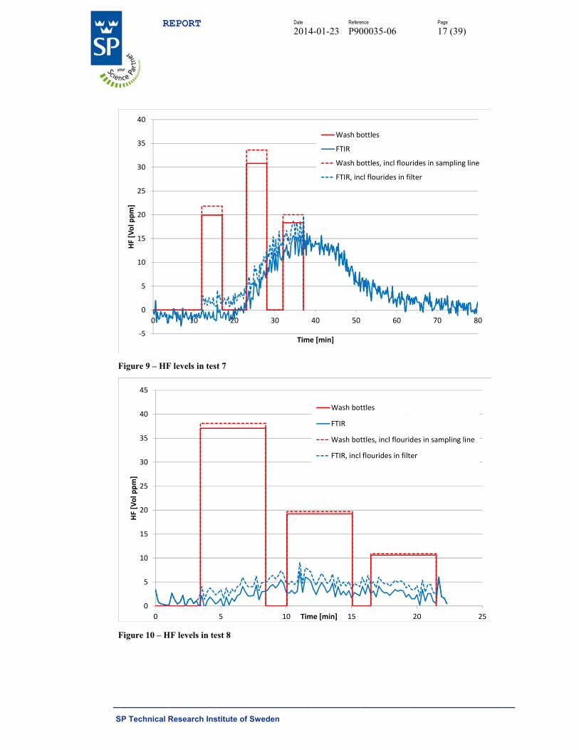
Figure 9 – HF
Figure 10 – H
‐5
0
5
10
15
20
25
30
35
40
0
HF [Vol ppm]
0
5
10
15
20
25
30
35
40
45
0
HF [Vol ppm]
REPORT
Research Ins
F levels in tes
HF levels in te
10
stitute of Swe
t 7
est 8
20
5
Date
2014
eden
30 4
Time
10 Tim
Refere
4-01-23 P90
40 50
e [min]
Wash b
FTIR
Wash b
FTIR, in
15me [min]
Wash bo
FTIR
Wash bo
FTIR, incl
ence
00035-06
0 60
bottles
bottles, incl flou
cl flourides in f
ttles
ttles, incl flour
l flourides in fil
Page
17 (3
70
urides in sampl
filter
20
ides in samplin
ter
39)
80
ing line
25
ng line

S
Fa
F
R
SP Technical
Figure 11 – Hamount of CO
Figure 12 – H
‐20
0
20
40
60
80
100
120
140
160
0
HF [Vol ppm]
‐5
0
5
10
15
20
25
30
35
0
HF [Vol ppm]
REPORT
Research Ins
HF levels in teOF2, the fluor
HF levels in te
5 1
10
stitute of Swe
est 11, NOTErides from CO
est 12
10 15
20
Date
2014
eden
E: in this test tOF2 are contr
20
Time
30Time [mi
Refere
4-01-23 P90
the FTIR meributing to th
25 30
e [min]
Wash bot
FTIR
Wash bot
FTIR, incl
40in]
Wash b
FTIR
Wash b
FTIR, in
ence
00035-06
easurement inhe wash bottl
35
ttles
ttles, incl flouri
flouride in filte
50
bottles
bottles, incl flou
ncl flouride in fi
Page
18 (3
ndicated a sige results abov
40 45
ides in samplin
er
60
urides in samp
ilter
39)
gnificant ve.
50
g line
70
ling line
S
F
Iepra
Iepra
Il
I5ls
L
Amiatar
R
SP Technical
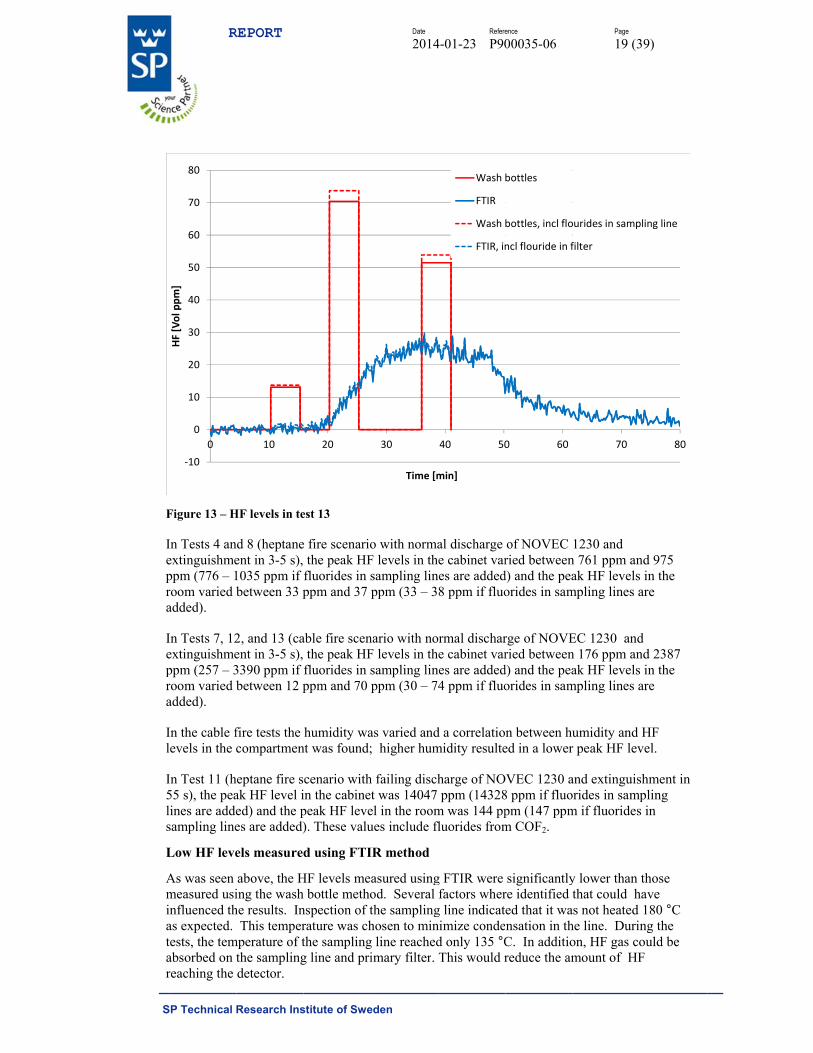
Figure 13 – H
In Tests 4 anextinguishmeppm (776 – 1room varied badded).
In Tests 7, 12extinguishmeppm (257 – 3room varied badded).
In the cable flevels in the c
In Test 11 (h55 s), the pealines are addesampling line
Low HF leve
As was seen measured usiinfluenced thas expected. tests, the temabsorbed on treaching the
‐10
0
10
20
30
40
50
60
70
80
0
HF [Vol ppm]
REPORT
Research Ins
HF levels in te
nd 8 (heptaneent in 3-5 s), 1035 ppm if between 33 p
2, and 13 (caent in 3-5 s), 3390 ppm if between 12 p
fire tests the compartmen
eptane fire sak HF level ied) and the pes are added)
els measured
above, the Hing the washhe results. In This temper
mperature of tthe samplingdetector.
10
stitute of Swe
est 13
e fire scenariothe peak HF
fluorides in sppm and 37
able fire scenthe peak HF
fluorides in sppm and 70
humidity want was found;
cenario within the cabinepeak HF leve). These valu
d using FTI
HF levels me bottle metho
nspection of trature was chthe samplingg line and pri
20
Date
2014
eden
o with normaF levels in thsampling linppm (33 – 3
nario with noF levels in thsampling linppm (30 – 74
as varied and; higher hum
h failing discht was 14047
el in the roomues include fl
IR method
asured usingod. Severalthe samplinghosen to ming line reachedimary filter.
30
Time [m
Refere
4-01-23 P90
al discharge e cabinet var
nes are added8 ppm if fluo
ormal dischare cabinet var
nes are added4 ppm if fluo
d a correlatiomidity resulte
harge of NOppm (14328
m was 144 ppfluorides from
g FTIR werefactors wher
g line indicatnimize conded only 135 °CThis would r
40 50
min]
Wash b
FTIR
Wash b
FTIR, in
ence
00035-06
of NOVEC ried between
d) and the peaorides in sam
rge of NOVEried between
d) and the peaorides in sam
n between hued in a lower
VEC 1230 a8 ppm if fluopm (147 ppmm COF2.
significantlyre identified ted that it wansation in thC. In additioreduce the am
0 60
bottles
bottles, incl flo
ncl flouride in f
Page
19 (3
1230 and n 761 ppm anak HF levels
mpling lines a
EC 1230 andn 176 ppm anak HF levels
mpling lines a
umidity and r peak HF lev
and extinguisorides in sampm if fluorides
y lower than that could h
as not heated he line. Durinon, HF gas comount of HF
70
ourides in samp
filter
39)
nd 975 in the are
d nd 2387 in the are
HF vel.
shment in pling
s in
those have
180 °C ng the ould be F
80
pling line
S
AlclstcAtfs
T
T
A
B
C
D
E
F
G
H
*c
*
TrErt
R
SP Technical
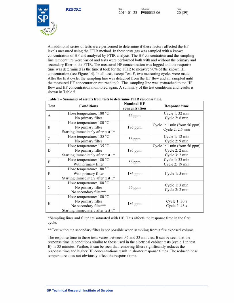
An additionalevels measuconcentrationline temperatsecondary filtime was deteconcentrationAfter the firsthe measuredflow and HF shown in Tab
Table 5 – Sum
Test
A H
B H
Star
C H
D H
Star
E H
F H
Star
G H
H
H
Star
*Sampling licycle.
**Test witho
The responseresponse timeE) is 33 minresponse timetemperature d
REPORT
Research Ins
al series of teured using then of HF and ture were varlter in the FTermined as thn (see Figuret cycle, the s
d HF concentconcentratio
ble 5.
mmary of res
Cond
Hose temperNo prim
Hose temperNo prim
rting immediHose temper
No primHose temper
No primrting immediHose temper
With primHose temper
With primrting immediHose temper
No primNo second
Hose temperNo prim
No secondrting immedi
nes and filte
out a seconda
e time in these in conditio
nutes. Furthere and higherdoes not obv
stitute of Swe
ests were perfe FTIR methanalysed byried and tests
TIR. The meahe time it tooe 14). In all tesampling linetration returnon monitored
ults from test
ditions
rature: 180 °Cmary filter rature: 180 °C
mary filter iately after terature: 135 °C
mary filter rature: 135 °C
mary filter iately after terature: 180 °Cmary filter rature: 180 °Cmary filteriately after terature: 180 °C
mary filter dary filter**rature: 180 °C
mary filter dary filter**iately after te
r are saturate
ary filter is n
se tests varieons similar tor, it can be ser HF concentviously affect
Date
2014
eden
formed to dehod. In these
FTIR analyss were perforasured HF cook for the FTests except Te was detachned to 0. Thed again. A su
ts to determiN
coC
C
est 1* C
C
est 1*C
C
est 1* C
C
est 1*
ed with HF. T
ot possible w
es between 0.o those used ieen that remotrations result the respons
Refere
4-01-23 P90
etermine if thtests gas wa
sis. The HF crmed both woncentrationTIR to measuTest F, two mhed from the e sampling l
ummary of th
ne FTIR respNominal HF oncentration
56 ppm
186 ppm
56 ppm
186 ppm
56 ppm
186 ppm
56 ppm
186 ppm
This affects
when samplin
.5 and 33 minin the electrioving filters lt in shorter rse time.
ence
00035-06
hese factors as sampled wconcentration
with and withwas logged
ure 90% of thmeasuring cyHF flow andline was rea
he test condit
ponse time.
n R
C
Cycle 1C
C
Cycle 1
CC
the response
ng from a fir
nutes. It can ical cabinet tsignificantly
response time
Page
20 (3
affected the Hith a known n and the samout the primand the respohe known HF
ycles were mad air sampledattached to thtions and resu
Response tim
Cycle 1: 32 mCycle 2: 6 m
: 1 min (fromCycle 2: 2.5 m
Cycle 1: 12 mCycle 2: 9 m: 1 min (fromCycle 2: 2 mCycle 3: 2 m
Cycle 1: 33 mCycle 2: 19 m
Cycle 1: 5 m
Cycle 1: 3 mCycle 2: 2 m
Cycle 1: 30Cycle 2: 45
e time in the
re exposed vo
be seen thatests (cycle 1
y reduces thees. The reduc
39)
HF
mpling ary and onse F ade. d until he HF ults is
me
min min
m 56 ppm)min
min min m 56 ppm)min min min min
min
min min
0 s 5 s
first
olume.
t the in test
e ced hose
S
Ftta
Tua
Tb1
R
SP Technical
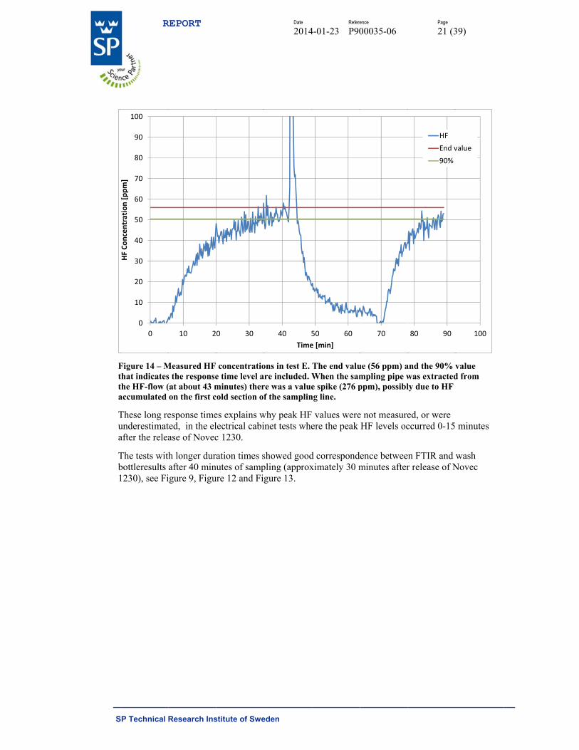
Figure 14 – Mthat indicatesthe HF-flow (accumulated
These long reunderestimatafter the relea
The tests withbottleresults 1230), see Fi
0
10
20
30
40
50
60
70
80
90
100
0
HF Concentration [ppm]
REPORT
Research Ins
Measured HF s the response(at about 43 mon the first c
esponse timeted, in the elase of Novec
h longer durafter 40 minigure 9, Figu
10 2
stitute of Swe
concentratioe time level aminutes) thercold section of
es explains wlectrical cabic 1230.
ation times snutes of sampure 12 and Fig
0 30
Date
2014
eden
ons in test E. re included. W
re was a valuef the samplin
why peak HFinet tests whe
showed goodpling (approxgure 13.
40 5
Time
Refere
4-01-23 P90
The end valuWhen the same spike (276 p
ng line.
values wereere the peak
d correspondximately 30 m
50 60
e [min]
ence
00035-06
ue (56 ppm) ampling pipe wppm), possibl
e not measureHF levels oc
ence betweeminutes after
70
Page
21 (3
and the 90% vwas extractedly due to HF
ed, or were ccurred 0-15
n FTIR and wr release of N
80 90
HF
End v
90%
39)
value d from
minutes
wash Novec
100
value
S
D
To(b
C
W
T
T
Is
Ft
R
SP Technical
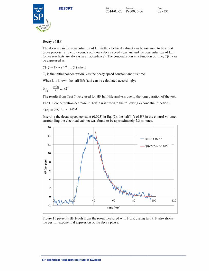
Decay of HF
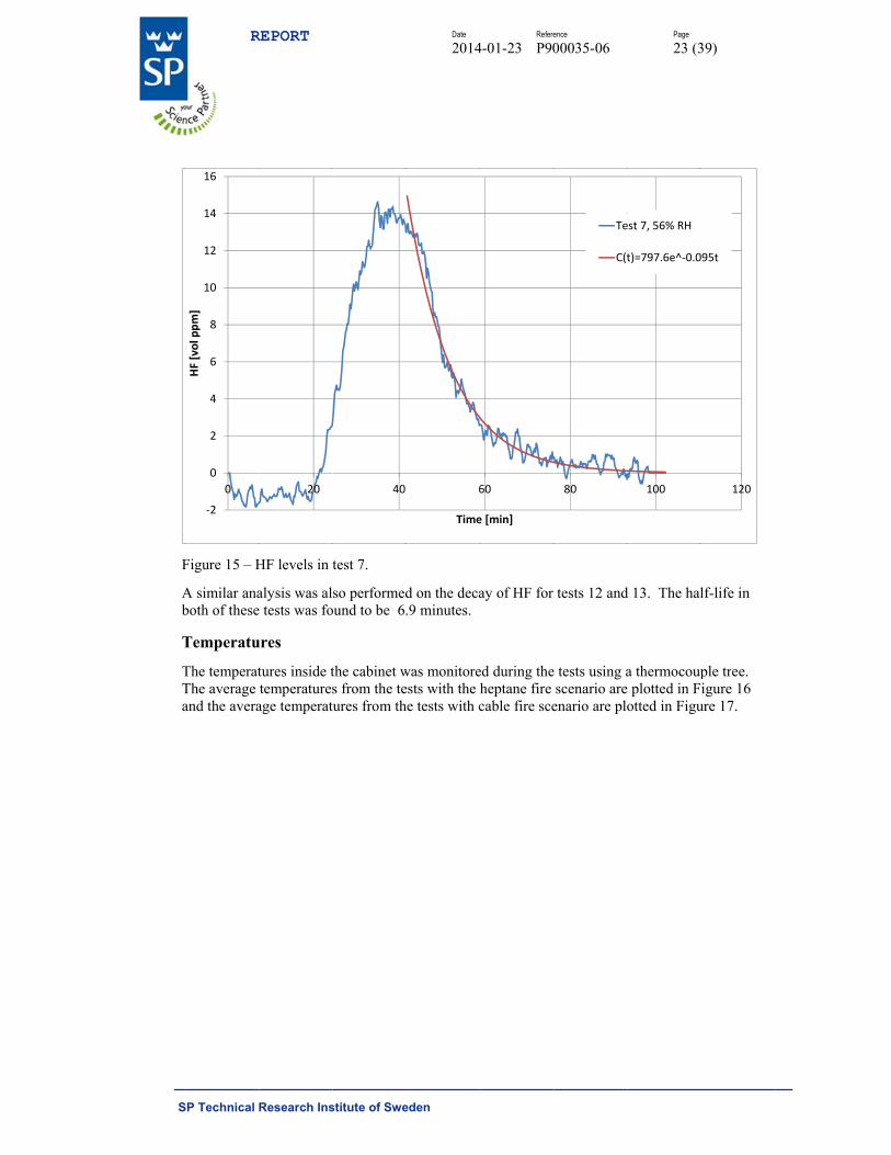
The decreaseorder process(other reactanbe expressed
∗
C0 is the initi
When k is kn
…
The results fr
The HF conc
797.6
Inserting the surrounding t
Figure 15 prethe best fit ex
‐2
0
2
4
6
8
10
12
14
16
0
HF [vol ppm]
REPORT
Research Ins
F
e in the conces [2], i.e. it dnts are alway
d as:
… (1) w
ial concentra
nown the half
… (2)
rom Test 7 w
centration dec
6 ∗ .
decay speedthe electrical
esents HF levxponential ex
20
stitute of Swe
entration of Hdepends only ys in an abun
where
ation, k is the
f-life (t1/2) ca
were used for
crease in Tes
d constant (0.l cabinet was
vels from thexpression of
40
Date
2014
eden
HF in the eleon a decay s
ndance). The
e decay speed
an be calcula
r HF half-life
st 7 was fitte
.095) in Eq. s found to be
e room measthe decay ph
6
Time
Refere
4-01-23 P90
ectrical cabinspeed consta
e concentratio
d constant an
ated accordin
e analysis du
ed to the follo
(2), the half-e approximat
sured with FThase.
60
e [min]
ence
00035-06
net can be asant and the coon as a funct
nd t is time.
ngly:
ue to the long
owing expon
-life of HF intely 7.3 minu
TIR during te
80
Te
C(t
Page
22 (3
sumed to be oncentration tion of time,
g duration of
nential functi
n the control utes.
est 7. It also
100
est 7, 56% RH
t)=797.6e^‐0.0
39)
a first of HF C(t), can
f the test.
ion:
volume
shows
120
95t
S
F
Ab
T
TTa
R
SP Technical
Figure 15 – H
A similar anaboth of these
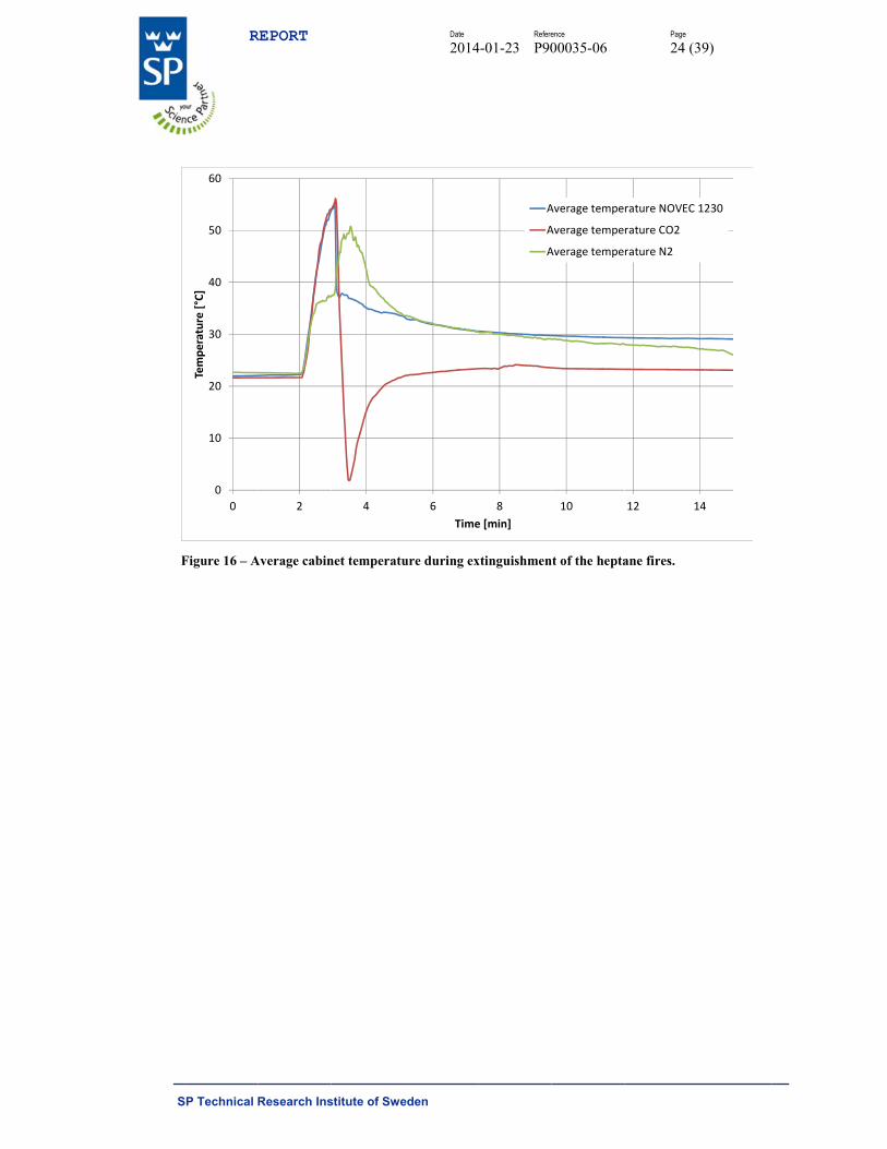
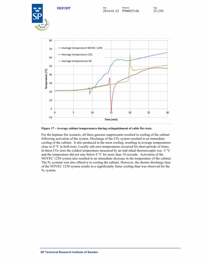
Temperatu
The temperatThe average and the avera
‐2
0
2
4
6
8
10
12
14
16
0
HF [vol ppm]
REPORT
Research Ins
HF levels in t
alysis was ale tests was fo
ures
tures inside ttemperatures
age temperat
20
stitute of Swe
test 7.
so performedound to be 6.
the cabinet ws from the tetures from th
40
Date
2014
eden
d on the deca.9 minutes.
was monitoreests with the he tests with c
6
Time
Refere
4-01-23 P90
ay of HF for
ed during theheptane fire cable fire sce
60
e [min]
ence
00035-06
tests 12 and
e tests using ascenario are
enario are plo
80
Te
C(t
Page
23 (3
d 13. The hal
a thermocoup plotted in Fotted in Figu
100
est 7, 56% RH
t)=797.6e^‐0.0
39)
lf-life in
ple tree. igure 16
ure 17.
120
95t
S
F
R
SP Technical
Figure 16 – A
0
10
20
30
40
50
60
0
Temperature [°C]
REPORT
Research Ins
Average cabin
2
stitute of Swe
net temperatu
4
Date
2014
eden
ure during ex
6
Time
Refere
4-01-23 P90
xtinguishmen
8
e [min]
A
A
A
ence
00035-06
nt of the hepta
10
Average tempe
Average tempe
Average tempe
Page
24 (3
ane fires.
12 1
rature NOVEC
rature CO2
rature N2
39)
14
1230
S
F
FfccIaNToN
R
SP Technical
Figure 17 - A
For the heptafollowing actcooling of thclose to 0 °CIn these CO2 and the tempNOVEC 123The N2 systemof the NOVEN2 system.
‐10
0
10
20
30
40
50
60
70
80
0
Temperature [°C]
REPORT
Research Ins
verage cabin
ane fire scenativation of the cabinet. It in both teststests the colerature did n0 system alsms was also
EC 1230 syst
5
Average tem
Average tem
Average tem
stitute of Swe
net temperatu
ario, all threehe system. Dt also producs. Locally suldest temperanot stay belowso resulted ineffective in
tem results in
10
mperature NOV
mperature CO2
mperatures N2
Date
2014
eden
ures during ex
e gaseous supischarge of ted in the mo
ub-zero tempeature measurw 0 °C for m
n an immediacooling the c
n a significan
0
Time
VEC 1230
Refere
4-01-23 P90
xtinguishmen
ppressants rethe CO2 systeost cooling, reratures occured by an indmore than 10 ate decrease icabinet. Howntly faster co
15
e [min]
ence
00035-06
nt of cable fir
esulted in coem resulted iesulting in avurred for sho
dividual thermseconds. Acin the tempe
wever, the shooling than w
20
Page
25 (3
re tests.
oling of the cin an immediverage temp
ort periods ofmocouple wactivation of trature of the
horter discharwas observed
25
39)
cabinet iate eratures f times. as -5 °C the cabinet. rge time
d for the
30
S
D
At
TTn
12
34
5678911111
1
11
*h
Flss
Ias
TmprdBcw
R
SP Technical
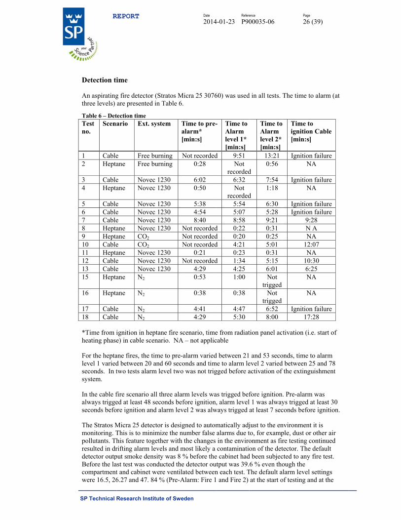
Detection ti
An aspiratingthree levels)
Table 6 – DetTest no.
Scena
1 Cable2 Hepta
3 Cable4 Hepta
5 Cable6 Cable7 Cable8 Hepta9 Hepta10 Cable11 Hepta12 Cable13 Cable15 Hepta
16 Hepta
17 Cable18 Cable
*Time from iheating phase
For the heptalevel 1 variedseconds. In tsystem.
In the cable falways triggeseconds befo
The Stratos Mmonitoring. Tpollutants. Thresulted in drdetector outpBefore the lacompartmentwere 16.5, 26
REPORT
Research Ins
ime
g fire detectoare presented
tection time ario Ext.
e Free ane Free
e Noveane Nove
e Novee Novee Noveane Noveane CO2 e CO2 ane Novee Novee Noveane N2
ane N2
e N2 e N2
ignition in hee) in cable sc
ane fires, the d between 20two tests alar
fire scenario ed at least 48ore ignition a
Micra 25 deteThis is to minhis feature torifting alarm put smoke deast test was cot and cabinet6.27 and 47.
stitute of Swe
or (Stratos Md in Table 6.
system Ta[
burning Nburning
ec 1230 ec 1230
ec 1230ec 1230 ec 1230 ec 1230 N
NN
ec 1230 ec 1230 Nec 1230
eptane fire sccenario. NA
time to pre-0 and 60 secorm level two
all three alar8 seconds befand alarm lev
ector is designimize the nogether with levels and m
ensity was 8 %onducted thet were ventila84 % (Pre-A
Date
2014
eden
Micra 25 3076.
Time to pre-alarm* [min:s]
Not recorded0:28
6:02 0:50
5:384:54 8:40
Not recordedNot recordedNot recorded
0:21 Not recorded
4:29 0:53
0:38
4:41 4:29
cenario, timeA – not applic
alarm variedonds and tim
o was not trig
rm levels wafore ignition
vel 2 was alw
gned to automnumber false
the changes most likely a % before thee detector ouated between
Alarm: Fire 1
Refere
4-01-23 P90
60) was used
- Time to Alarm level 1* [min:s]
d 9:51 Not
recorded6:32 Not
recorded5:545:07 8:58
d 0:22 d 0:20 d 4:21
0:23 d 1:34
4:25 1:00
0:38
4:47 5:30
e from radiatcable
d between 21me to alarm legged before a
as trigged bef, alarm level
ways trigged
matically adjalarms due tin the envirocontaminatio
e cabinet hadutput was 39.n each test. T and Fire 2)
ence
00035-06
d in all tests.
Time to Alarm level 2* [min:s]
13:21
d 0:56
7:54
d 1:18
6:305:28 9:21 0:31 0:25 5:01 0:31 5:156:01 Not
trigged Not
trigged 6:52 8:00
tion panel ac
and 53 secoevel 2 variedactivation of
fore ignitionl 1 was alwayat least 7 sec
just to the ento, for examponment as firon of the det
d been subjec6 % even tho
The default aat the start o
Page
26 (3
The time to a
Time to ignition C[min:s]
Ignition fNA
Ignition fNA
Ignition fIgnition f
9:28N ANA
12:0NA
10:36:25NA
NA
Ignition f17:2
tivation (i.e.
onds, time to d between 25 f the extingui
. Pre-alarm wys trigged at conds before
nvironment itple, dust or ore testing contector. The dcted to any fiough the larm level se
of testing and
39)
alarm (at
Cable
failure A
failure A
failurefailure 8
A A
7 A
0 5
A
A
failure 8
start of
alarm and 78 shment
was least 30 ignition.
t is other air ntinued
default ire test.
ettings d at the
S
eeao
C
Cws
Thapp
Twoc
T
TTn
O
R
SP Technical
end of the tesexplanations accumulationor etching of
Corrosion
Coupons of cweighed befosuppression t
Two couponsheights in theatmosphere vplaced at 0.5mplaced at 1.5m
The corrosionwhere treatedof hydrochlocoupons whe
The coupons
Table 7 – MaTest no.
Co
1
4
10
11
12
13
18
Observations
Test Test
desp Ther
Test
REPORT
Research Ins
st series thesfor the majo
n of soot (althf lenses in the
carbon steel, ore exposuretests.
s of each mee cabinet (at varied with hm above the m above the
n products wd with a 5% sric acid and
ere then rewe
from test 1,
ss loss from cupon Mas
[mg1 52 35 66 915 1316 1617 418 619 2720 1321 1322 1723 1624 6
s:
12 (NOVEC11 (NOVECite being exp
re was little d13 (NOVEC
stitute of Swe
e levels had or differenceshough the dee device from
copper and ze to the enviro
etal were exp0.5 m and 1.
height in the floor in the floor in the
were removedsolution of athe zinc coup
eighed and th
4, 10, 11, 12
copper couposs loss
g/dm2] Ave
lo5.58 .44
6.91 9.37 3.01 6.24
4.31 6.45 7.21 3.42 3.08 7.92 6.58
6.18
C, 80% RH) cC, slow dischposed to the hdifference in C 1230) and T
Date
2014
eden
increased tos in alarm levetector filter m the exposu
zinc (25 mmonment in th
osed in each.5 m above thcompartmencabinet and tcabinet. The
d using differamidosulfuricpons where p
he mass loss
2, 13 and 18
ons. erage mass oss [g/m2]
0.45
0.82
1.47
0.54
2.04
1.56
1.14
coupons hadharge) couponhighest fluorthe average
Test 18 (N2)
Refere
4-01-23 P90
48.6, 49.02 vel between was changed
ure to hydrog
m x 25 mm) whe electrical c
h test. The cohe floor) to d
nt. Test coupthe test coup
e coupons wh
rent picklingc acid, the stepickled in a scalculated.
where select
Co
Almos
Mass distributed
UnevenHeavily af
Mass distributed
Mass lodistributed
UnevenHeavily af
Mass lodistributed
d the highest ns had the seride levels. mass loss of.
ence
00035-06
and 81.8 %.test 1 and te
d after every gen fluoride.
were cleaned cabinet durin
oupons wherdetermine if pons with evepons with oddhere weighed
g liquors. Theeel coupons saturated gly
ted for evalu
omment
st unaffected
loss evenly d on the surfanly affected.ffected patchloss evenly d on the surfaoss unevenlyd on the surfanly affected.ffected patchoss unevenlyd on the surfa
level of correcond lowest
f the coupons
Page
27 (3
Possible est 19 might b
second or th
with ethanong the fire
re placed at dthe corrosivien numbers wd numbers wd after the fir
e copper couwith a 50%
ycine solution
uation.
R
face
hes.
face y face
hes. y face
rosion. t corrosion le
s for Test 10
39)
be the hird test)
ol and
different ity of the where
were re tests.
upons solution n. The
Rank
1
3
5
2
7
6
4
evels
(CO2),

S
TTn
O
TTn
O
R
SP Technical
Table 8 – MaTest no.
Cou
1
4
10 11
11 11
12 12
13 22
18 22
Observations
Test Test
desp Ther
Test
Table 9 – MaTest no.
Cou
1
4
10 11
11 11
12 12
13 22
18 22
Observations
Test In ge
possiAppe
REPORT
Research Ins
ss loss from supon Mas
[mg/1 132 305 226 2215 15816 1217 4418 7919 29820 17521 11222 18623 16924 102
s:
12 (NOVEC11 (NOVECite being exp
re was little d13 (NOVEC
ss loss from zupon Mas
[mg/1 7.2 7.5 156 2715 21016 13017 18318 23919 3220 8421 53322 40323 20724 11
s:
13 (NOVECeneral, the mible explanatendix 2).
stitute of Swe
steel couponsss loss /dm2]
Avelo
3.38 0.48 2.38 2.75 8.65
27.2 4.16 9.33 8.19 5.45 2.11 6.38 9.58 2.07
C, 80% RH) cC, slow dischposed to highdifference beC 1230) and T
zinc coupons.ss loss /dm2]
Avelo
.40
.27 5.85 7.7 0.73 0.58 3.02 9.78 1.87
4.39 3.63 3.92 7.33
16.7
C, normal dismass loss of z
tion is that zi
Date
2014
eden
s. erage mass oss [g/m2]
2.20
2.26
14.3
6.18
23.7
15.0
13.6
coupons hadharge) couponhest fluoride etween averaTest 18 (N2)
. erage mass oss [g/m2]
0.74
2.18
17.1
21.2
20.4
46.9
16.2
scharge) coupzinc couponsinc is more s
Refere
4-01-23 P90
Rank
1
2
5
3
7
6
4
d the highest ns had the thlevels. ge mass loss.
Rank
1
2
4
6
5
7
3
pons had thes was greatersensitive to a
ence
00035-06
level of corrhird lowest co
s for coupons
e highest lever in NOVEC acidic conditi
Page
28 (3
rosion. orrosion leve
s in Test 10 (
el of corrosio1230 tests. A
ions/low pH
39)
els
(CO2),
on A (see

S
C
Tt9
TMMM
Ie
Ie
Ie
Wech
Tf
Rrm
R
SP Technical
Comparison
The metal mathose expose9223 [3], in T
Table 10 – MMetal Mass loss (g/Metal loss (g
In the test thaequivalent to
In the test thaequivalent to
In the test thaequivalent to
When compaextinguishingcoupons betwhumidity in t
The corrosionfor those usin
Regardless orequire cleanmetals expos
REPORT
Research Ins
n to outdoor
ass loss of cod to 1 year inTable 9.
ass loss in tes
/m2) C3 1 yeg/m2) after fi
at had the woo about 3 mon
at had the woo about 4.5 ye
at had the woo about 1 mon
aring the resug agent), therween the diffthe compartm
n damage to ng CO2 and N
f extinguishmning (decontased to combu
stitute of Swe
environmen
opper, steel an a medium
st compared t
ear ire tests
orst effect onnths in a C3
orst effect onears in a C3
orst effect onnth in a C3 e
ults from testre is no obviferent systemment (compar
the zinc couN2.
ment systemamination) afustion gases a
Date
2014
eden
nt according
and zinc coupcorrosive ou
to 1 year in m
5<0.4
n copper (Tesenvironment
n zinc (Test 1environment
n steel (Test environment.
t 10, 13 and ous differenc
m alternativesre test 12 and
upons was m
m and fire scenfter extinguisand the gaseo
Refere
4-01-23 P90
g to ISO 922
pons exposeutdoor enviro
medium corroCu
<….≤12 45 – 2.04
st 12), the mt.
13), the masst.
12), the mas.
18 (same firece in corrosios. The resultsd 13).
ore severe fo
nario tested,shment of a fous agents an
ence
00035-06
23
d in these tesonment, C3 a
osive outdoorZn
5<….≤150.74 – 46
mass loss due
s loss due to
s loss due to
e scenario, don damage tos seem to be
or tests using
it is likely thfire to prevennd their degr
Page
29 (3
sts are compaccording to I
r environmen
5 200<.9 2.20
to corrosion
corrosion wa
corrosion w
different o steel or copmore sensiti
g NOVEC 12
hat the cabinnt corrosion radation prod
39)
pared to ISO
nt. Fe
<….≤400 0 – 23.7
n was
as
was
pper ive to the
230 than
net will of
ducts.
S
C
Ths
Fd
S
R
SP Technical
Cabinet pre
The pressureheptane fire sscenario are p
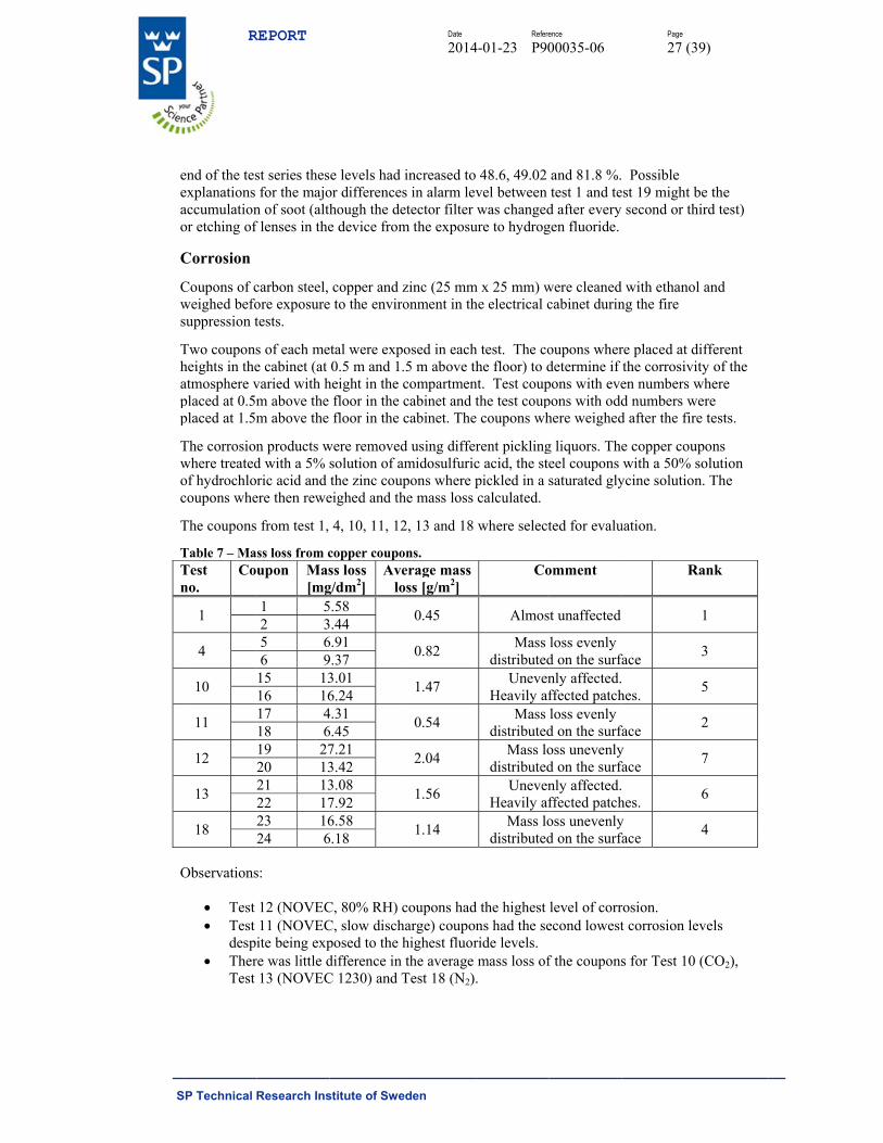
Figure 18 – Cdue to malfun
Several obser
The nsyste
The p The p Durin
‐35
‐30
‐25
‐20
‐15
‐10
‐5
0
5
10
15
0
Pressure [Pa]
REPORT
Research Ins
essure
in the cabinscenario are presented in
Cabinet pressunctioning pre
rvations can
negative preem probably pressure in thpressure in thng pre-burn,
1 2
stitute of Swe
net was monitpresented inFigure 19.
ure measuredessure sensor.
be made con
ssure in the ereduced the he CO2 test vhe NOVEC the fire caus
3
Date
2014
eden
tored during Figure 18 an
d in heptane .
ncerning the
electrical cabamount of tovaried betwe1230 test varsed a pressur
4 5
Time
Refere
4-01-23 P90
the tests. Thnd the pressu
fire tests. NO
results.
binet after acoxic gases leeen 13 Pa andried betweenre rise of 12
5 6
[min]
ence
00035-06
he pressure foure for the te
OTE that Test
ctivation of taving the cabd -5 Pa. n 0 and -27 PPa in the cab
7
Test
Test
Test
Page
30 (3
for the tests wests with cabl
t 16 (N2) is m
the NOVEC binet.
Pa. binet.
8 9
8, NOVEC 123
9, CO2
2, Free burnin
39)
with the le fire
missing
1230
10
0
g

S
F
O
R
SP Technical
Figure 19 - C
Observations
The nsyste
The c The c The c The p
was c Durin
‐30
‐25
‐20
‐15
‐10
‐5
0
5
10
15
20
0
Pressure [Pa]
REPORT
Research Ins
abinet pressu
s:
negative preem probably cabinet presscabinet presscabinet presspressure meaclosed. ng pre-burn,
5
stitute of Swe
ure measured
ssure in the ereduced the sure in the Csure in the Nsure in the Nasured in the
the fire caus
10
Date
2014
eden
d in cable fire
electrical cabamount of to
CO2 test varieN2 test variedNOVEC 1230e cabinet was
sed a pressur
15 2
Time
Refere
4-01-23 P90
e tests.
binet after acoxic gases leed between 5d between 120 tests varieds not affected
re rise in the
20 25
e [min]
ence
00035-06
ctivation of taving the cab Pa and -7 P
2 Pa and -15 Pd between 15d when the Ø
cabinet of up
30
Test 13, NOVE
Test 10, CO2
Test 18, N2
Test 19, NOVE
Page
31 (3
the NOVEC binet.. a. Pa. and -27 Pa.
Ø32 mm vent
p to 15 Pa.
35
EC 1230
EC 1230 closed
39)
1230
t opening
40
d vent
S
O
Tcc
F
F
R
SP Technical
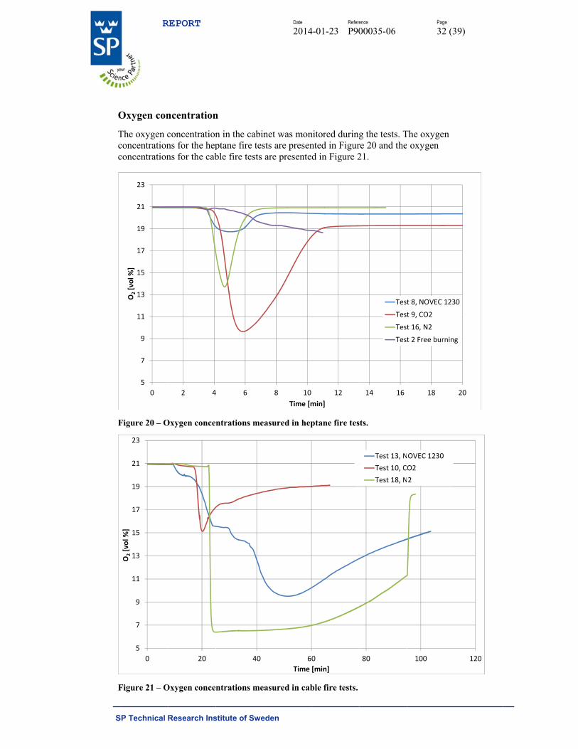
Oxygen con
The oxygen cconcentrationconcentration
Figure 20 – O
Figure 21 – O
5
7
9
11
13
15
17
19
21
23
0
O2[vol %
]
5
7
9
11
13
15
17
19
21
23
0
O2[vol %
]
REPORT
Research Ins
ncentration
concentrationns for the hepns for the cab
Oxygen conce
Oxygen conce
2 4
20
stitute of Swe
n
n in the cabinptane fire tesble fire tests
ntrations me
ntrations me
4 6
40
Date
2014
eden
net was monsts are presenare presente
asured in hep
asured in cab
8 10
Time [m
6
Time
Refere
4-01-23 P90
nitored duringnted in Figurd in Figure 2
ptane fire tes
ble fire tests.
12
min]
0
[min]
ence
00035-06
g the tests. Tre 20 and the21.
sts.
14 16
Test
Test
Test
Test
80
Test 13, N
Test 10, C
Test 18, N
Page
32 (3
The oxygen oxygen
18
t 8, NOVEC 123
t 9, CO2
t 16, N2
t 2 Free burning
100
OVEC 1230
O2
2
39)
20
30
g
120
S
TNci
Iddi
TNe
C
Aenio8ce
R
SP Technical
The oxygen cNOVEC 123cabinet). It min the humidi
In the CO2 tedue to the reldisplaces oxyignition 7:27
There was a lN2 tests. In texplains the l
CO2 exting
A separate teextinguisher navy ship. Thinhibit extingopenings on 89B, classifiecoupling on textinguish a
REPORT
Research Ins
concentration0. The oxyg
may be that tity trap insta
est, the oxygelatively high ygen to the to [min:s] time
large differenthe cable testlow oxygen
uishment i
est was perfoon a small phe goal was tguishment ofeach side as ed accordingtop of the cab2.80 m2 pool
stitute of Swe
n appears to en concentra
the extinguishalled in the o
en level risesdensity of C
op of the cabe for this test
nce in oxygets the pyrolyslevels after e
n a decomm
ormed to analpool fire in ato investigatef the fire. Thshown in Fig
g to the SS-Ebinet. Classil fire contain
Date
2014
eden
be over-estimation should hing agent w
oxygen analy
s quite rapidlCO2. It accumbinet. This mt.
en concentratsis from the extinguishme
missioned e
lyze the effecdecommissioe if obstructi
he cabinet wagure 22. The
EN 3-7 standafication 89B
ning 89 liters
Refere
4-01-23 P90
mated in the be ≤15% (ap
was absorbedyser.
ly after dischmulates in th
may also be th
tions after dicables continent.
electrical ca
ctiveness of oned electricions inside a as well ventie carbon dioxard [4]) was
B indicates ths of industria
ence
00035-06
heptane fireppr 6% NOVd in the desic
harge of the Che bottom of he reason for
ischarge of thnues through
abinet from
a carbon diocal cabinet frship board elated through
xide extinguidischarged th
hat the extingl heptane and
Page
33 (3
e scenario usiVEC 1230 in
cant (Drierit
CO2. This mthe cabinet a
r relatively fa
he agent in thh the tests. Th
m a navy sh
oxide fire rom a Netherelectrical cabh six ventilatisher (classifhrough a NA
guisher can d water.
39)
ing the
te) used
might be and ast re-
he two his
hip
rlands binet will tion fication ATO
S
F
TN
R
SP Technical
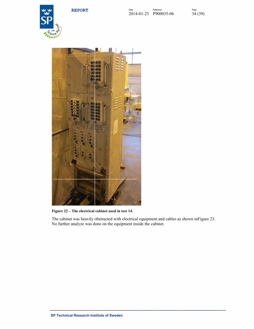
Figure 22 – T
The cabinet wNo further an
REPORT
Research Ins
The electrical
was heavily onalyze was d
stitute of Swe
cabinet used
obstructed wdone on the e
Date
2014
eden
d in test 14.
with electricaquipment ins
Refere
4-01-23 P90
l equipmentside the cabi
ence
00035-06
and cables ainet.
Page
34 (3
as shown inF
39)
igure 23.
S
F
Aoc
F
Tct
R
SP Technical
Figure 23 – O
A small heptother tests ancabinet as sh
Figure 24 – F
Thermocoupcabinet, 2/3 dtemperatures
REPORT
Research Ins
Obstructions i
ane pool firend the HHR cown in 24.
Fire tray locat
les were placdistance to th during the t
stitute of Swe
in the electric
e was used ascurve is show
ted under the
ced inside thhe top of the test are show
Date
2014
eden
cal cabinet
s the fire souwn in Figure
e cabinet.
he electrical ccabinet and
wn in Error!
Refere
4-01-23 P90
urce. The fire4. The fuel p
cabinet at 1/3at the top of Reference s
ence
00035-06
e was the sampan was plac
3 distance to f the cabinet. source not fo
Page
35 (3
me as that useced undernea
the top of thThe measur
ound.. The c
39)
ed in the ath the
he red carbon
S
dt34
Ticeec
F
R
SP Technical
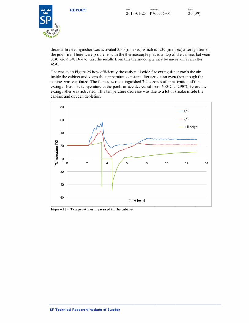
dioxide fire ethe pool fire.3:30 and 4:304:30.
The results ininside the cabcabinet was vextinguisher.extinguisher cabinet and o
Figure 25 – T
‐60
‐40
‐20
0
20
40
60
80
0Temperature [°C]
REPORT
Research Ins
extinguisher There were 0. Due to thi
n Figure 25 hbinet and keeventilated. Th The temperwas activate
oxygen deple
Temperatures
2
stitute of Swe
was activateproblems wis, the results
how efficienteps the temphe flames we
rature at the ped. This tempetion.
s measured in
4
Date
2014
eden
ed 3:30 (min:ith the therm
s from this th
tly the carboerature consere extinguispool surface perature decr
n the cabinet
6
Tim
Refere
4-01-23 P90
:sec) which imocouple plachermocouple
on dioxide firtant after actshed 3-4 secodecreased fr
rease was du
8
e [min]
ence
00035-06
is 1:30 (min:ced at top ofmay be unce
re extinguishtivation evenonds after acrom 600°C toe to a lot of s
10
Page
36 (3
sec) after ignf the cabinet bertain even a
her cools the n then thoughctivation of tho 290°C befosmoke inside
12
1/3
2/3
Full heigh
39)
nition of between
after
air h the he ore the e the
14
ht
S
CNEf
Tretat
Tta
Fitfbp
Tldpf
At
Tcch
TtotN
Tt2ta
IPa
R
SP Technical
ConclusioNOVEC 123Extinguishmfires in 8 to 9
The N2 systemre-ignition. Inextinguishmetest the cableand 3:14 [minthe re-ignitio
The re-ignitiothe density oaccumulate in
Fire suppressin the cabinettests, the peafire tests withbetween 257 ppm and 74 p
The rate of dlevels of HF discharge of ppm and peakfrom the prod
A correlationtests. As the
The tests shocompartmentcabinet indichalf-life betw
The CO2 systtemperaturesoccurred for the tests usinNOVEC 123
The aspiratinthe time to pr20 and 60 secthe level twoafter ignition
In the cable fPre-alarm waand alarm lev
REPORT
Research Ins
ons and co0 extinguishent time vari
9 seconds wh
m performedn the test witent. Multiplees did not re-n:s] respectiv
on time increa
ons observedf these gasen the bottom
sion testing wt varied betw
ak HF levels h the normal ppm and 33
ppm.
discharge of tor fluorides NOVEC 123k HF level (fduction of C
n between huhumidity in
owed that thet decline withated the decr
ween 6.9 and
tem was the following reshort period
ng NOVEC 10 system res
ng fire detectre-alarm variconds and tim
o alarm did non).
fire tests, all as triggered ≥vel 2 was trig
stitute of Swe
ommentshed the fire faied between hile N2 exting
d best in prevth the CO2 sye cable scenaignite, in thevely. When tased signific
d after extings. They are
m of the cabin
with NOVECween 776 ppmin the compadischarge of90 ppm and
the NOVEC produced. In30 into the cafluorides) in OF2 released
umidity and Hthe electrica
e airborne HFh time. An anrease followe9.8 minutes
most efficienelease of thiss of times. T230 and the
sulted in a sig
tor was very ied between me to alarm ot trigger bef
three alarm l≥ 48 secondsggered ≥ 7 se
Date
2014
eden
astest in both2 and 5 secoguished them
venting re-igystem the cab
ario tests were other two tethe Ø32 mm
cantly to 13:5
guishment wisignificantly
net and below
C 1230 resultm and 1035 partment varief NOVEC 12the peak HF
1230 systemn the test witabinet, peak the room wa
d by the therm
HF levels in al cabinet wa
F levels in a nalysis of thed a first ord.
nt the coolins suppressant
The temperatuN2 systems.
gnificantly fa
effective at d21 and 53 selevel 2 variefore the extin
levels were ts before, alareconds befor
Refere
4-01-23 P90
h the heptaneonds. CO2 exm in 10 to 59
gnition,; in thbles re-ignite
re performedests the times
m ventilation o58 [min:s].
ith CO2 and y denser thanw the fires po
ted in the relppm for the hed between 3230, the peak
F levels in the
m was also foth the heptanHF level (flu
as 147 ppm.mal degradat
the compartmas increased,
contaminatee HF levels i
der exponenti
ng the cabinett close to 0 °ure reductionHowever, th
faster cooling
detecting fireeconds, time ed between 2nguishment s
triggered befrm level 1 ware cable bund
ence
00035-06
e and cable fixtinguished th
seconds.
he cable scened 7:27 [min
d with NOVEs to re-ignitioopening in th
NOVEC 123n air and are wositioned at 1
ease of HF. heptane fire
33 ppm and 3k HF levels ie compartme
ound to have ne fire and a uorides) in thThese valuetion of NOV
ment was fouthe peak HF
d, but not vein the room sial decay wit
t with averag°C. Locally sn in the cabinhe shorter disg rate.
es. In the heto alarm lev5 and 78 secsystem was a
fore ignition as triggered ≥dle ignition.
Page
37 (3
fire scenarioshe heptane an
nario test thern:s] after EC 1230 and on were 1:27he cabinet w
30 might be dwould tend t1 m height.
The peak HFtests. For th
38 ppm. In tin the cabinetent varied be
an effect on reduced ratehe cabinet ws include flu
VEC 1230.
und for the cF levels decre
entilated, surrounding th a HF conc
ge cabinet sub-zero tempnet was similscharge time
ptane fire scvel 1 varied bconds. In twactivated (60
of the cable ≥ 30 seconds
39)
s. nd cable
re was no
in one 7 [min:s] as sealed
due to to
F levels he same the cable t varied tween 30
the e of as 14328
uorides
cable fire eased.
the centration
peratures lar for
e of the
enario between
wo tests, 0 seconds
bundle. s before
S
TTpct
Iahg
Rcd
Twmt
R
SP Technical
The detector,This could bepossible explcould be accuthe device ca
In general, thagents were shumidity in tgreater in tes
Regardless ocabinet wherdecontaminat
The dischargwas no highemeasured ovethe cabinet dr
REPORT
Research Ins
, Stratos Mice seen in driflanation for tumulation ofaused by HF
he differencesmall. The cothe compartmts with NOV
f extinguishmre any of thested to preven
ge of the extiner than the over pressure inropped to a n
stitute of Swe
cra 25, was sfting pre-firethe major diff soot (despitexposure.
e in corrosionorrosion of s
ment than forVEC 1230 tha
ment systemse agents arent corrosion t
nguishment verpressure cn this test sernegative pres
Date
2014
eden
sensitive to re smoke densfferences in ate regular det
n damage to ssteel and copr the zinc couan for those
m and fire scen discharged tto metallic m
systems did caused by firries was 15 Pssure.
Refere
4-01-23 P90
repeated exposity outputs aalarm level btector filter c
steel or coppper coupons upons. The cwith CO2 an
nario tested to extinguish
materials in th
cause an overe during the Pa. During an
ence
00035-06
osure to the gand alarm levbetween the fchanges) or e
per coupons bwas more se
corrosion of znd N2.
it is likely thh a fire will hhe cabinet.
er pressure inpre-burningnd after disc
Page
38 (3
gases from thvel settings. Afirst and the etching of len
by the three ensitive to thzinc coupons
hat an electrichave to be
n the cabinet time. The hiharge the pre
39)
he tests. A last test nses in
gaseous he s was
cal
t but it ighest essure in
S
R
SFP
__
M
R
SP Technical
Reference1. EN 12. Öber3. ISO
ClassStand
4. SwedChar
SP TechnicFire TechnoPerformed by
_Signature_1 Michael Rah
REPORT
Research Ins
es 13823:2010, rg, Tomas, M9223, Corrossification, dedardization, dish Standardracteristics, p
cal Researcology - Fire D
m, Alexande
stitute of Swe
Single BurnMiljöriskanalysion of metaetermination 2012 d SS-EN 3-7
performance
ch Institute Dynamics
er Leanderss
Date
2014
eden
ning Item, 20ys, Sweden,
als and alloysand estimati
7:2004+A1:2requirement
of Sweden
Ex
__S
on T
Refere
4-01-23 P90
10 2009
s - Corrosivition, Internati
2007 Portablets and test me
n
xamined by
Signature_2
Tommy Hertz
ence
00035-06
ty of atmosphional Organi
e fire extinguethods
zberg
Page
39 (3
heres - zation for
uishers – Par
39)
rt 7: