electrical principles, components and systems v7.0 2010€¦ · · 2015-03-24all matter is...
TRANSCRIPT
Copyright © Tinson Training Ltd
1
Electrical Principles, Components and Systems v7.0 2010
Copyright © 2010 Tinson Training Ltd
All rights reserved worldwide.
No part of this publication may be reproduced, stored in a retrieval system (other than the computer
used to download when supplied as an ebook), or transmitted in any form or by any other means,
whether mechanical, photocopying, recording or otherwise, without the prior permission of the
author.
The publisher has strived to be as accurate as possible in the creation of this publication.
The publisher will not be responsible for any losses or damages of any kind incurred by the reader
whether directly or indirectly arising from the use of information found in this document.
The author of this document reserves the right to make changes without notice. The publisher
assumes no responsibility or liability whatsoever on the behalf of the reader of this document.
Copyright © Tinson Training Ltd
2
Contents Chapter Title
1 Basic Electrical Principles
2 Electrical Circuits
3 DC Supplies
4 AC Supplies Single Phase
5 AC Supplies Three Phase
6 Transformers
7 Electrical Test Equipment
8 Three Phase Motors
9 Single Phase Induction Motors
10 DC Motors
11 Contactors and Relays
12 Control Circuits
13 Principles of Inverters
14 Electrical Safety
15 Cables and Protection
16 Fault Finding Techniques
Appendix A Electricity at Work Regulations 1989
Appendix B BS7671-2008
Appendix C Glossary of Electrical / Electronic Terms
Appendix D Electrical Symbols
Appendix E Index of Protection Ratings
Appendix F Conductor Cable Colours
Appendix G Electrical Colour Codes
Appendix H Three Phase Motor Current Calculations
Appendix I SI Units
Electrical Principles, Components and Systems INTRODUCTION
Copyright © Tinson Training Ltd
3
Introduction
These notes are intended for anyone who has little electrical knowledge or experience and would like
to understand more about electrical systems and equipment. They are ideal for someone whose job
could easily involve some form of electrical testing and component replacement. The notes are
aimed at industrial electrical engineering and is not for those people who wish to install electrical
supplies.
The notes are written in a language that is easy to follow and keeps the maths to a minimum and
are therefore aimed at someone who wishes to understand enough to be able to carry out electrical
checks and repairs without getting too involved in electrical theory.
At the end of each chapter there are exercises that allow you to check out your understanding of the
topics covered.
Electrical Principles, Components and Systems Chapter 1: BASIC ELECTRICAL PRINCIPLES
Copyright © Tinson Training Ltd
1
Chapter 1
Basic Electrical Principles At the end of this section you will have an understanding of
• basic electrical quantities
• electrical power
• conductors and insulators
• simple circuit theory
• Ohms Law
Electrical Principles, Components and Systems Chapter 1: BASIC ELECTRICAL PRINCIPLES
Copyright © Tinson Training Ltd
2
Basic Principles
Electrical Physics
As a starting point it is important to understand what is happening within an electrical system
to take away the unknown and feel confident about working with electricity. First we will
consider the physics behind electricity.
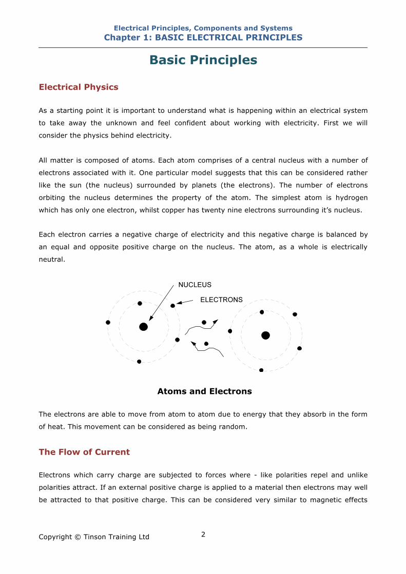
All matter is composed of atoms. Each atom comprises of a central nucleus with a number of
electrons associated with it. One particular model suggests that this can be considered rather
like the sun (the nucleus) surrounded by planets (the electrons). The number of electrons
orbiting the nucleus determines the property of the atom. The simplest atom is hydrogen
which has only one electron, whilst copper has twenty nine electrons surrounding it’s nucleus.
Each electron carries a negative charge of electricity and this negative charge is balanced by
an equal and opposite positive charge on the nucleus. The atom, as a whole is electrically
neutral.
Atoms and Electrons
The electrons are able to move from atom to atom due to energy that they absorb in the form
of heat. This movement can be considered as being random.
The Flow of Current Electrons which carry charge are subjected to forces where - like polarities repel and unlike
polarities attract. If an external positive charge is applied to a material then electrons may well
be attracted to that positive charge. This can be considered very similar to magnetic effects
Electrical Principles, Components and Systems Chapter 1: BASIC ELECTRICAL PRINCIPLES
Copyright © Tinson Training Ltd
3
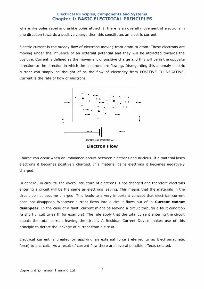
where like poles repel and unlike poles attract. If there is an overall movement of electrons in
one direction towards a positive charge then this constitutes an electric current.
Electric current is the steady flow of electrons moving from atom to atom. These electrons are
moving under the influence of an external potential and they will be attracted towards the
positive. Current is defined as the movement of positive charge and this will be in the opposite
direction to the direction in which the electrons are flowing. Disregarding this anomaly electric
current can simply be thought of as the flow of electricity from POSITIVE TO NEGATIVE.
Current is the rate of flow of electrons.
Electron Flow
Charge can occur when an imbalance occurs between electrons and nucleus. If a material loses
electrons it becomes positively charged. If a material gains electrons it becomes negatively
charged.
In general, in circuits, the overall structure of electrons is not changed and therefore electrons
entering a circuit will be the same as electrons leaving. This means that the materials in the
circuit do not become charged. This leads to a very important concept that electrical current
does not disappear. Whatever current flows into a circuit flows out of it. Current cannot
disappear. In the case of a fault, current might be leaving a circuit through a fault condition
(a short circuit to earth for example). The rule apply that the total current entering the circuit
equals the total current leaving the circuit. A Residual Current Device makes use of this
principle to detect the leakage of current from a circuit..
Electrical current is created by applying an external force (referred to as Electromagnetic
force) to a circuit. As a result of current flow there are several possible effects created.
Electrical Principles, Components and Systems Chapter 1: BASIC ELECTRICAL PRINCIPLES
Copyright © Tinson Training Ltd
4
Chemical Effect Generally there is no change in a metal during the passage of an electric current but some
materials are chemically changed by the passage of electric current. Solutions of acid in water
are decomposed. The chemical affects of an electric current are utilised in electroplating and
accumulators.
Heating Effect When electric current flows through a substance that has resistance to the flow of electric
current, discussed later, that substance becomes heated. Conductors will posses resistance
and some conductors are arranged to posses resistance to utilise the heating effect.
An immersion heater comprises of a length of mineral insulated cable in which the conductors
are resistance wires. An electric fire element is a coil of resistance wire on a heatproof
insulating rod. A lighting bulb has a very fine resistance wire known as the filament. The
filament heats under the effect of the current until it becomes incandescent and emits light.
Magnetic Effect An electric current passing through a conductor produces a magnetic field around that
conductor. The polarity and intensity of the magnetic field is dependent on the direction and
size of current respectively. Motors make use of the magnetic effects to create forces between
magnetic fields that in turn create motion.
Electrical Units Voltage Voltage can be described as the driving force or pressure behind electricity. The physical term
electromotive force (emf) is used to describe this quantity although the term is not used
generally. Voltage is measured in volts and is often the fixed quantity in an electrical system.
The voltage is the supply of energy to a circuit and consequently is supplied from a number of
sources. A DC system will have a fixed DC voltage supplied from say a battery or DC Power
Supply Unit. An AC system will have its AC supply typically from the mains or on occasions a
local generator.
Electrical Principles, Components and Systems Chapter 1: BASIC ELECTRICAL PRINCIPLES
Copyright © Tinson Training Ltd
5
Current Current is the flow of electrons that arises from applying a voltage to a circuit. Current is
measured in amps (amperes). A flow of 1 amp is approximately six million, million, million
electrons flowing per second. Current will flow when a voltage is applied and there is a
complete circuit (or path). The total current flowing in a circuit will be determined by the
resistance.
Resistance Resistance is determined, amongst other things, by the material where all materials have a
property called resistivity. This property depends upon the ability of electrons in that material
to be able to leave their orbits around the nucleus and contribute to current flow. Materials
where this can happen easily will be referred to as conductors whereas materials where this
cannot happen easily will be referred to as non conductors or insulators. Resistivity is
measured in Ohms / metre.
Some typical values of resistivity are shown in the table below
Material Resistivity (!/m) Type
Silver 1.59 X 10⁻⁸ Conductor
Copper 1.72 X 10⁻⁸ Conductor
Gold 2.44 X 10- Conductor
Aluminium 2.82 X 10⁻⁸ Conductor
Tungsten 5.6 X 10⁻⁸ Conductor
Platinum 1.06 X 10⁻⁷ Conductor
Carbon 3.5 X 10⁻⁵ Conductor
Germanium 4.6 X 10⁻¹ Semi Conductor
Silicon 6.4 X 10² Semi Conductor
Glass 1010 - 1014 Insulator
Hard Rubber 1013 Insulator
Teflon 1022 - 1024 Insulator
Resistance is the opposition to the flow of current. Resistance is measured in Ohms, symbol !
and is determined by the type and size of material in which the current is attempting to flow.
Electrical Principles, Components and Systems Chapter 1: BASIC ELECTRICAL PRINCIPLES
Copyright © Tinson Training Ltd
6
The size of the material will be given by it’s length and it’s cross sectional area.
Resistance is calculated from
resistivity of the material X length
Resistance = cross sectional area (csa)
It can be seen from this formula that length and cross sectional area have an effect on
resistance.
As length increases, resistance increases and vice versa. As cross sectional area increases
resistance decreases and vice versa.
This is important in as much as cables have to be of a given size to be adequate for a
particular function. Cables that are longer than they need to be could possess too much
resistance and cables that are too thin could also possess too much resistance.
Conductors In a conductor the electrons are not firmly attached to the nucleus and are normally
interchanging between atoms in a random manner. They can easily leave their orbit when an
external potential is applied and so will cause current to flow. A conductor is classified as a
material in which there will easily be current flow i.e. one that possesses a low resistivity.
Examples: silver, copper, aluminium,
Insulators In an insulator the electrons are firmly attached to the nucleus and will not be moved from
their orbit when an external potential is applied. The interchange of electrons will not take
place and consequently there will be no current flow. An insulator is defined as material that
will not pass current and will have a high value of resistivity. (rubber, PVC, porcelain,…)
Energy Energy is the capacity of an object or a system to do work and is measured in Joules.
energy can neither be created nor destroyed.
Electrical Principles, Components and Systems Chapter 1: BASIC ELECTRICAL PRINCIPLES
Copyright © Tinson Training Ltd
7
Energy is converted from one source to another
Example:
A lamp converts electrical energy into light energy.
A motor converts electrical energy into mechanical energy
A battery converts chemical energy into electrical energy
The potential energy of water in a highland reservoir is converted into kinetic energy as the
water flows down the inlet tube where it is converted into electrical energy by a generator
driven from a turbine.
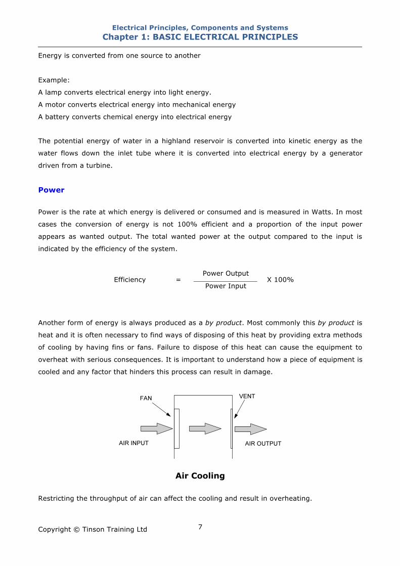
Power Power is the rate at which energy is delivered or consumed and is measured in Watts. In most
cases the conversion of energy is not 100% efficient and a proportion of the input power
appears as wanted output. The total wanted power at the output compared to the input is
indicated by the efficiency of the system.
Power Output Efficiency =
Power Input X 100%
Another form of energy is always produced as a by product. Most commonly this by product is
heat and it is often necessary to find ways of disposing of this heat by providing extra methods
of cooling by having fins or fans. Failure to dispose of this heat can cause the equipment to
overheat with serious consequences. It is important to understand how a piece of equipment is
cooled and any factor that hinders this process can result in damage.
Air Cooling Restricting the throughput of air can affect the cooling and result in overheating.
Electrical Principles, Components and Systems Chapter 1: BASIC ELECTRICAL PRINCIPLES
Copyright © Tinson Training Ltd
8
Power is lost through resistance as this causes heat. Conductors possess resistance and this
generates heat and results in a power loss. For example a loud speaker coil possesses
resistance. This resistance is not needed in the process of converting electrical power to sound
power but will produce heat. This heat will need to be dissipated to protect the speaker from
overheating.
Electrical Power Electrical power is supplied to a circuit whenever a voltage is applied and current flows. The
power supplied to that circuit will the product of voltage times the current and will be
measured in watts, symbol W
POWER VOLTAGE CURRENT (Watts)
= (Volts)
X (Amps)
A car starter motor taking 200A from a 12V battery will be taking 2400W of power.
Also
POWER (Watts) CURRENT(Amps) =
VOLTAGE (Volts)
A 2400W heater element connected to a 240V supply will take 10A.
For a given power requirement the lower the operating voltage; the higher the current
consumption and vice versa. For example the car starter motor takes 200A due the low voltage
whereas the same power requirement using a 240V motor would only consume 10A.
By looking at the power rating of some items of equipment it is possible to establish from this
calculation the level of current that will be consumed. It is important to appreciate that some
items of equipment such as motors specify the mechanical output that is available as a
maximum. If the motor is not on it’s maximum load (which it ought not to be) the current
drawn would be less. By looking at the motor power rating it is possible to determine the
maximum current that should be drawn by the motor.
Electrical Principles, Components and Systems Chapter 1: BASIC ELECTRICAL PRINCIPLES
Copyright © Tinson Training Ltd
9
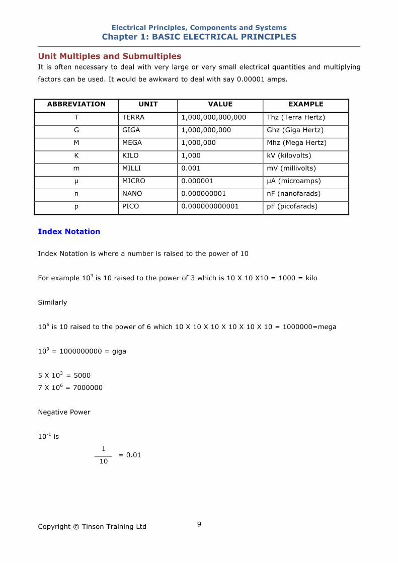
Unit Multiples and Submultiples It is often necessary to deal with very large or very small electrical quantities and multiplying
factors can be used. It would be awkward to deal with say 0.00001 amps.
ABBREVIATION UNIT VALUE EXAMPLE
T TERRA 1,000,000,000,000 Thz (Terra Hertz)
G GIGA 1,000,000,000 Ghz (Giga Hertz)
M MEGA 1,000,000 Mhz (Mega Hertz)
K KILO 1,000 kV (kilovolts)
m MILLI 0.001 mV (millivolts)
" MICRO 0.000001 "A (microamps)
n NANO 0.000000001 nF (nanofarads)
p PICO 0.000000000001 pF (picofarads)
Index Notation Index Notation is where a number is raised to the power of 10
For example 103 is 10 raised to the power of 3 which is 10 X 10 X10 = 1000 = kilo
Similarly
106 is 10 raised to the power of 6 which 10 X 10 X 10 X 10 X 10 X 10 = 1000000=mega
109 = 1000000000 = giga
5 X 103 = 5000
7 X 106 = 7000000
Negative Power
10-1 is
1
10 = 0.01
Electrical Principles, Components and Systems Chapter 1: BASIC ELECTRICAL PRINCIPLES
Copyright © Tinson Training Ltd
10
10-3 is
1
103 = 0.003 = mili
5 X 10⁻³ A = 5mA
8 X 10⁻⁶A = 8"A (micro Amp)
Ohm’s Law The most commonly used principle in electrical systems is Ohm’s Law, that gives the
relationship between voltage, current and resistance.
VOLTAGE = CURRENT " RESISTANCE
Current v Voltage Graph
The relationship between voltage and current is linear i.e. as the voltage increases then the
current increases and vice versa. Simple calculations can be carried out to determine the
current that will flow in a circuit of a given resistance.
Alternative forms of Ohms Law:
VOLTAGE
CURRENT = RESISTANCE
and
VOLTAGE RESISTANCE =
CURRENT
Electrical Principles, Components and Systems Chapter 1: BASIC ELECTRICAL PRINCIPLES
Copyright © Tinson Training Ltd
11
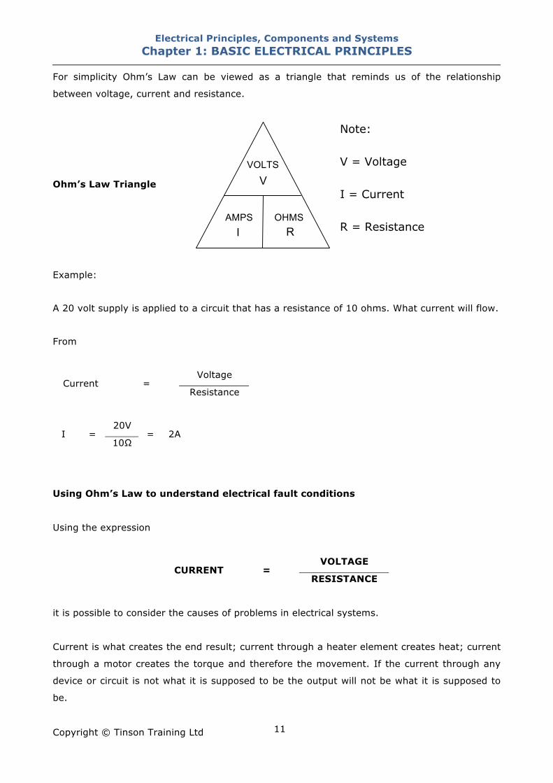
For simplicity Ohm’s Law can be viewed as a triangle that reminds us of the relationship
between voltage, current and resistance.
Ohm’s Law Triangle
Note: V = Voltage I = Current R = Resistance
Example:
A 20 volt supply is applied to a circuit that has a resistance of 10 ohms. What current will flow.
From
Voltage
Current = Resistance
20V
I = 10!
= 2A
Using Ohm’s Law to understand electrical fault conditions
Using the expression
VOLTAGE CURRENT =
RESISTANCE
it is possible to consider the causes of problems in electrical systems.
Current is what creates the end result; current through a heater element creates heat; current
through a motor creates the torque and therefore the movement. If the current through any
device or circuit is not what it is supposed to be the output will not be what it is supposed to
be.
VOLTS
AMPS OHMS
V
I R
Electrical Principles, Components and Systems Chapter 1: BASIC ELECTRICAL PRINCIPLES
Copyright © Tinson Training Ltd
12
Too little current
If the current flow through a item of equipment is too low the output from the equipment, in
whatever energy form this is, will be low (ie insufficient heat) this would be created by either a
(a) too low voltage applied to the equipment
or
(b) a too higher resistance within the equipment
If the voltage supplied to equipment is low then this could mean that the supply voltage
coming into the equipment is low which needs to be investigated. Alternatively the supply
voltage could be at it’s correct level but there is a fault which is causing a volt drop within the
control circuit. See Volt Drops.
If the resistance of the equipment (or the circuit supplying the equipment) is too high then this
could be caused by a loose connection, a worn contact.
The extreme situation would be ZERO current. This situation would be caused by
(a) no supply voltage
or
(b) a very, very high (infinite) resistance which would mean that the circuit has no path
through it and there is a complete disconnection of the circuit. This condition is known
as an OPEN CIRCUIT. The symptom of an open circuit is the equipment or system
does not operate.
Too much current
If a circuit tried to take too much current this would be caused by
(a) too much voltage (a higher than normal voltage)
or
(b) too little resistance.
Electrical Principles, Components and Systems Chapter 1: BASIC ELECTRICAL PRINCIPLES
Copyright © Tinson Training Ltd
13
An over-voltage condition would suggest that there is a problem with the supply. This
condition is fairly rare for extended periods but can happen as a surge for a short duration of
time. Such effects might occur for example during electric storms.
Too little resistance is caused when the circuit path is in someway reduced. This can be caused
by conducting parts coming into contact such as cables with damaged insulation coming into
contact with each other or the casing or enclosure. This condition is referred to as a SHORT
CIRCUIT.
NOTE: Excessive current would be prevented by the operation of a circuit protection device
such as a fuse or circuit breaker.
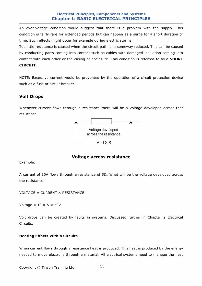
Volt Drops Whenever current flows through a resistance there will be a voltage developed across that
resistance.
Voltage across resistance
Example:
A current of 10A flows through a resistance of 5!. What will be the voltage developed across
the resistance.
VOLTAGE = CURRENT " RESISTANCE
Voltage = 10 " 5 = 50V
Volt drops can be created by faults in systems. Discussed further in Chapter 2 Electrical
Circuits.
Heating Effects Within Circuits
When current flows through a resistance heat is produced. This heat is produced by the energy
needed to move electrons through a material. All electrical systems need to manage the heat
Electrical Principles, Components and Systems Chapter 1: BASIC ELECTRICAL PRINCIPLES
Copyright © Tinson Training Ltd
14
that is produced and ensure that it is displaced. Therefore all conductors (and other parts that
will absorb the heat from conductors) will have a method by which heat is removed. In many
cases that heat removal is by convection and radiation into the surrounding air.
It is important to appreciate that any change in the system that will reduce the ability of the
conductor to cool will cause heat to be retained and therefore the conductor could overheat.
Such things might include the covering of cables, leaving cables wound on a reel, covering
ventilation holes or failures of fans.
The heat within a conductor can rise considerably which could eventually lead to the melting of
insulation and subsequent exposure of live conductors which exposes a real danger of electric
shock. Heat can also increase to the extent that there is a danger of fire. Any given conductor
in a circuit will have a maximum current that can flow through it whilst allowing for the heat
that is generated to be removed by the cooling method. Currents in excess of this value will
cause potential overheating and dangers. Conductors therefore can never be allowed to have
more than this maximum value of current flowing in them and a means has to be provided to
prevent this over-current. Such protection is provided by the use of fuses and circuit breakers.
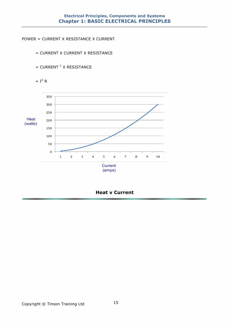
The heat produced within a conductor would be given by I2R *(the square of the current
multiplied by the resistance). This means that the heat that is produced is proportional to the
square of the current.
If the current in a conductor doubled the heat would increase by a factor or four (two
squared). If the current in a conductor increased by factor of three the heat would increase by
a factor of nine (three squared). This can explain why conductors will soon get very hot within
a circuit if excessive current is allowed to flow.
This principle applies to any conductor in any position within a circuit including cables,
switches, connectors, plugs, sockets, fittings etc.
* This formula is determined by combining Ohms Law with the formula for power.
POWER = VOLTAGE X CURRENT
From Ohms Law
VOLTAGE = CURRENT X RESISTANCE
By replacing VOLTAGE in the Power equation with CURRENT X RESISTANCE we have
Electrical Principles, Components and Systems Chapter 1: BASIC ELECTRICAL PRINCIPLES
Copyright © Tinson Training Ltd
15
POWER = CURRENT X RESISTANCE X CURRENT
= CURRENT X CURRENT X RESISTANCE
= CURRENT 2 X RESISTANCE
= I2 R
Heat v Current
Electrical Principles, Components and Systems Chapter 1: BASIC ELECTRICAL PRINCIPLES
Copyright © Tinson Training Ltd
16
ON LINE EXERCISE Click here to access Chapter 1: Basic Electrical Principles - On Line Exercises
Electrical Principles, Components and Systems Chapter 2: ELECTRICAL CIRCUITS
Copyright © Tinson Training Ltd
17
Chapter 2
Electrical Circuits At the end of this section you will have an understanding of
• series circuits
• parallel circuits
• series parallel circuits
Electrical Principles, Components and Systems Chapter 2: ELECTRICAL CIRCUITS
Copyright © Tinson Training Ltd
18
Electrical Circuits
Series Circuits
Series Circuit
Consider a circuit where two items are connected together in such a way that the current path is
through both components. There are two basic features
• the same current will flow through both component
• there will be volt drops across both components
Voltage Law in closed circuit:
The sum of the voltage drops around the circuit will add up to the supply voltage, i.e. there is no
voltage lost.
Suppose the two components have resistances of R1 and R2, then the volt drops across the
resistances will be calculated from Ohms Law as the product of current and resistance.
Volt drop across R1 = I " R1
Volt drop across R2 = I " R2
The total volt drop around the circuit will then be
i i
R1 R2
Vsupply
+ -
Electrical Principles, Components and Systems Chapter 2: ELECTRICAL CIRCUITS
Copyright © Tinson Training Ltd
19
(I " R1) + (I " R2)
The supply voltage can be expressed as current times total circuit resistance
I " R(total)
Therefore
Supply voltage = Volt drop across R1 + Volt drop across R2
I " R(total) = (I " R1) + (I " R2)
Note that I is common to all parts in the equation and therefore can be removed. This gives,
R(total) = R1 + R2
This circuit is a SERIES CIRCUIT where the total resistance is given by
R(total) = R1 + R2
Generally expression:
THE TOTAL RESISTANCE IN A SERIES CIRCUIT IS THE SUM OF ALL THE INDIVIDUAL
RESISTANCES
R(total) = R1 + R2 + R3 + ....
Examples Three resistances of 10!, 25! and 35! are connected in series.
The total resistance will be
10 + 25 + 35 = 70!
A cable of total resistance 0.3! is joined to a cable with resistance 0.15!.
The total cable resistance will be
0.3 + 0.15 = 0.45!
Electrical Principles, Components and Systems Chapter 2: ELECTRICAL CIRCUITS
Copyright © Tinson Training Ltd
20
Switches connected in series.
In this simple circuit shown, what condition do the switches need to
be in for the lamp to light ?
The two switches both need to be operated or turned on.
This can be phrased as switch A AND switch B will need to be on for
the lamp to operate.
This is an example of a control function where the lamp is controlled
by the two switches A and B. By connected the switches in series it
gives this specific control function of requiring both switches to be
on.
In logic control circuits this function is known as the AND function
Parallel Circuits
Parallel Circuits
Now consider a circuit where two resistances are connected such that they are both connected to
the same supply. There are two basic features
A
B
+ve
-ve
LAMP
Vsupply
i
R
R2
i i
i
+ -
i1
i2
Electrical Principles, Components and Systems Chapter 2: ELECTRICAL CIRCUITS
Copyright © Tinson Training Ltd
21
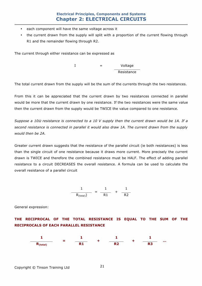
• each component will have the same voltage across it
• the current drawn from the supply will split with a proportion of the current flowing through
R1 and the remainder flowing through R2.
The current through either resistance can be expressed as
I = Voltage
Resistance
The total current drawn from the supply will be the sum of the currents through the two resistances.
From this it can be appreciated that the current drawn by two resistances connected in parallel
would be more that the current drawn by one resistance. If the two resistances were the same value
then the current drawn from the supply would be TWICE the value compared to one resistance.
Suppose a 10! resistance is connected to a 10 V supply then the current drawn would be 1A. If a
second resistance is connected in parallel it would also draw 1A. The current drawn from the supply
would then be 2A.
Greater current drawn suggests that the resistance of the parallel circuit (ie both resistances) is less
than the single circuit of one resistance because it draws more current. More precisely the current
drawn is TWICE and therefore the combined resistance must be HALF. The effect of adding parallel
resistance to a circuit DECREASES the overall resistance. A formula can be used to calculate the
overall resistance of a parallel circuit
1 1 1
R(total)) =
R1 +
R2
General expression:
THE RECIPROCAL OF THE TOTAL RESISTANCE IS EQUAL TO THE SUM OF THE
RECIPROCALS OF EACH PARALLEL RESISTANCE
1 1 1 1
R(total) =
R1 +
R2 +
R3 …
Electrical Principles, Components and Systems Chapter 2: ELECTRICAL CIRCUITS
Copyright © Tinson Training Ltd
22
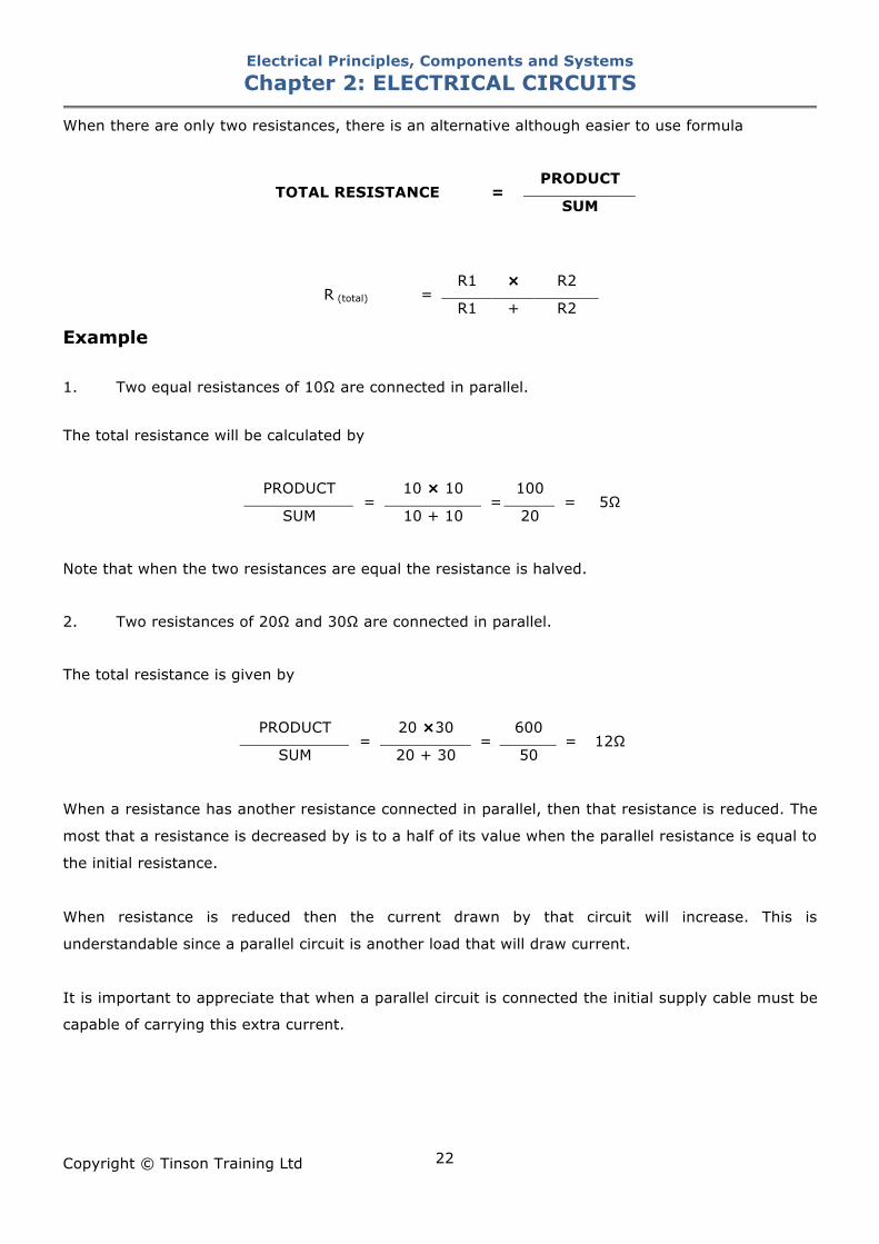
When there are only two resistances, there is an alternative although easier to use formula
PRODUCT
TOTAL RESISTANCE = SUM
R1 " R2 R (total) =
R1 + R2
Example 1. Two equal resistances of 10! are connected in parallel.
The total resistance will be calculated by
PRODUCT 10 " 10 100
SUM =
10 + 10 =
20 = 5!
Note that when the two resistances are equal the resistance is halved.
2. Two resistances of 20! and 30! are connected in parallel.
The total resistance is given by
PRODUCT 20 "30 600
SUM =
20 + 30 =
50 = 12!
When a resistance has another resistance connected in parallel, then that resistance is reduced. The
most that a resistance is decreased by is to a half of its value when the parallel resistance is equal to
the initial resistance.
When resistance is reduced then the current drawn by that circuit will increase. This is
understandable since a parallel circuit is another load that will draw current.
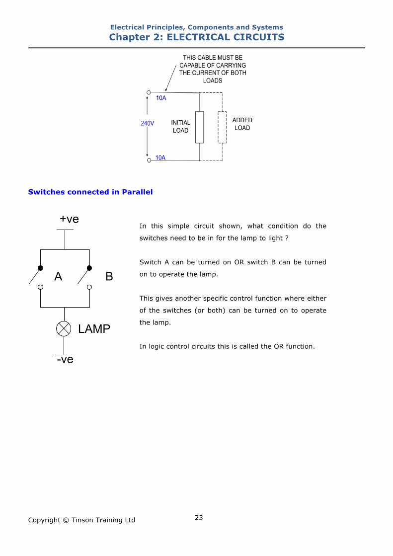
It is important to appreciate that when a parallel circuit is connected the initial supply cable must be
capable of carrying this extra current.
Electrical Principles, Components and Systems Chapter 2: ELECTRICAL CIRCUITS
Copyright © Tinson Training Ltd
23
Switches connected in Parallel
In this simple circuit shown, what condition do the
switches need to be in for the lamp to light ?
Switch A can be turned on OR switch B can be turned
on to operate the lamp.
This gives another specific control function where either
of the switches (or both) can be turned on to operate
the lamp.
In logic control circuits this is called the OR function.
A B
+ve
-ve
LAMP
Electrical Principles, Components and Systems Chapter 2: ELECTRICAL CIRCUITS
Copyright © Tinson Training Ltd
24
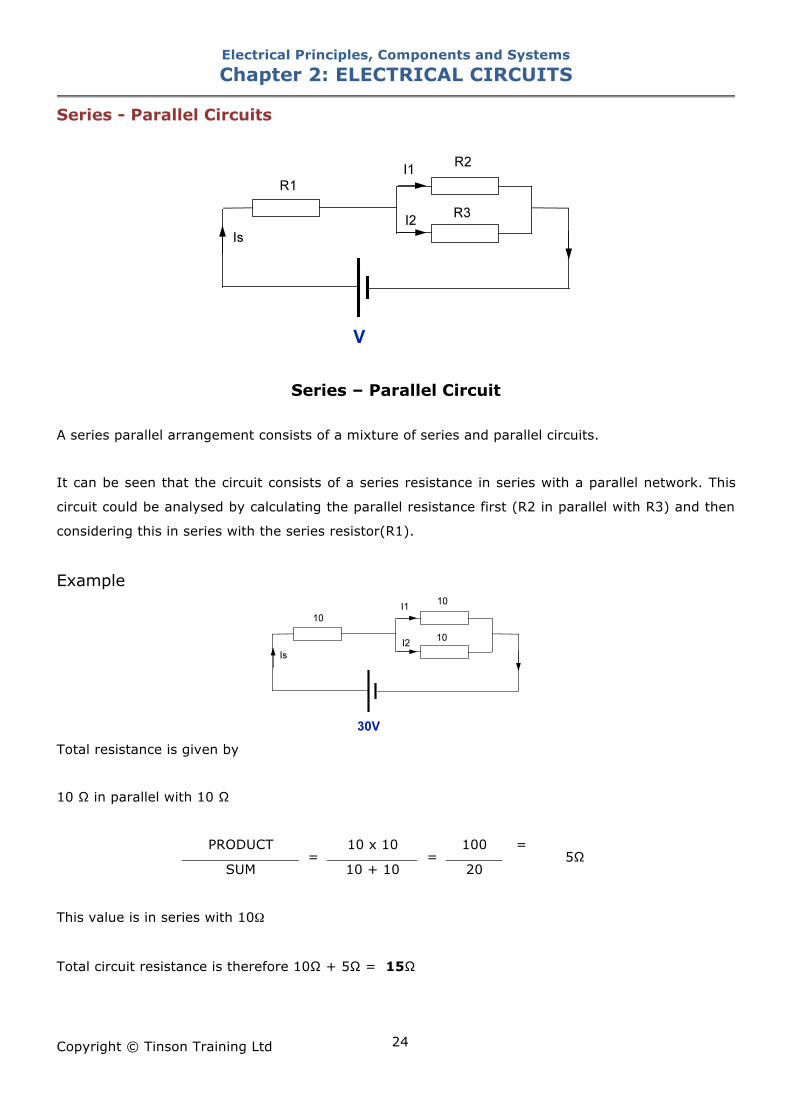
Series - Parallel Circuits
Series – Parallel Circuit
A series parallel arrangement consists of a mixture of series and parallel circuits.
It can be seen that the circuit consists of a series resistance in series with a parallel network. This
circuit could be analysed by calculating the parallel resistance first (R2 in parallel with R3) and then
considering this in series with the series resistor(R1).
Example
Total resistance is given by
10 ! in parallel with 10 !
PRODUCT 10 x 10 100 =
SUM =
10 + 10 =
20 5!
This value is in series with 10!
Total circuit resistance is therefore 10! + 5! = 15!
Electrical Principles, Components and Systems Chapter 2: ELECTRICAL CIRCUITS
Copyright © Tinson Training Ltd
25
30V Circuit Current =
15! = 2A
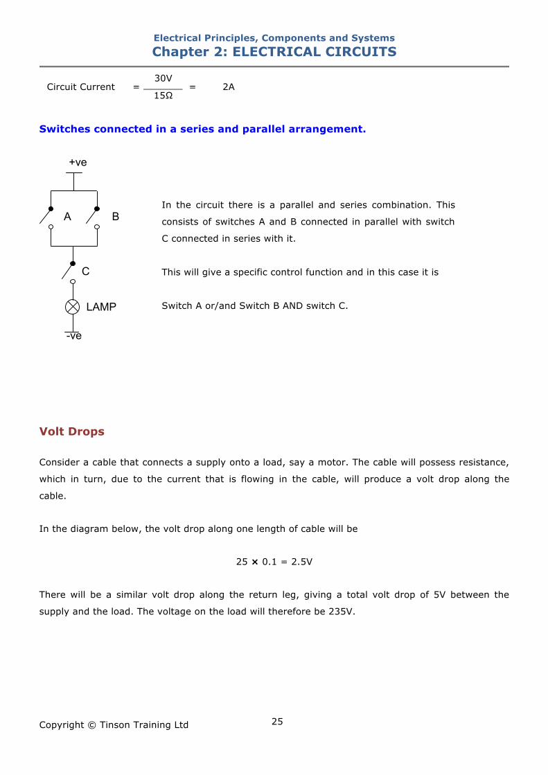
Switches connected in a series and parallel arrangement.
In the circuit there is a parallel and series combination. This
consists of switches A and B connected in parallel with switch
C connected in series with it.
This will give a specific control function and in this case it is
Switch A or/and Switch B AND switch C.
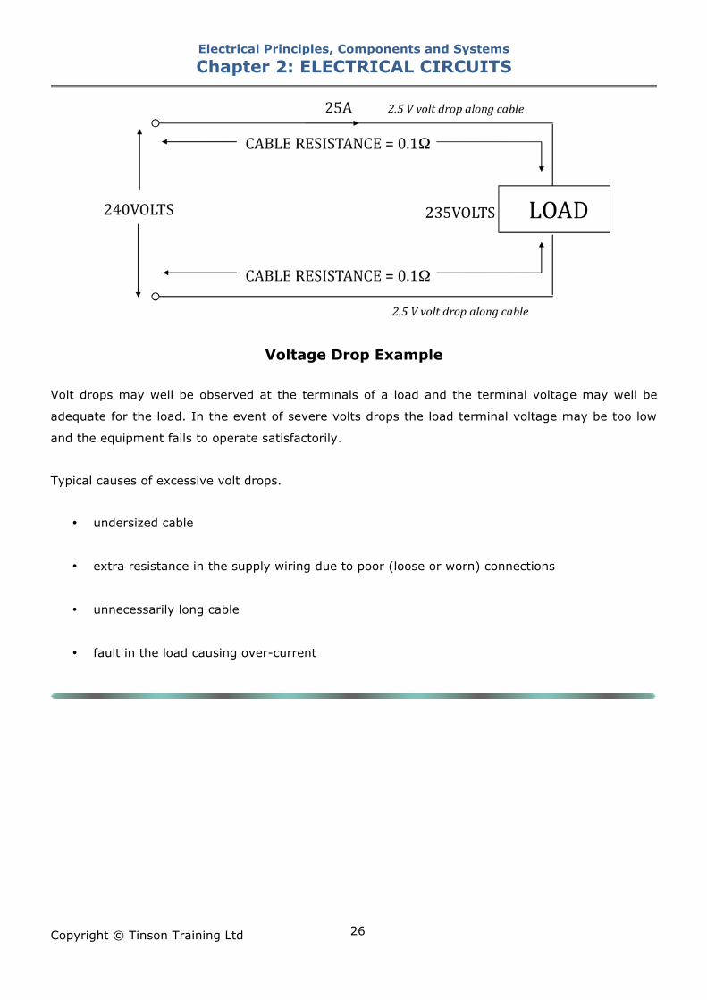
Volt Drops Consider a cable that connects a supply onto a load, say a motor. The cable will possess resistance,
which in turn, due to the current that is flowing in the cable, will produce a volt drop along the
cable.
In the diagram below, the volt drop along one length of cable will be
25 " 0.1 = 2.5V
There will be a similar volt drop along the return leg, giving a total volt drop of 5V between the
supply and the load. The voltage on the load will therefore be 235V.
A B
+ve
-ve
LAMP
C
Electrical Principles, Components and Systems Chapter 2: ELECTRICAL CIRCUITS
Copyright © Tinson Training Ltd
26
Voltage Drop Example
Volt drops may well be observed at the terminals of a load and the terminal voltage may well be
adequate for the load. In the event of severe volts drops the load terminal voltage may be too low
and the equipment fails to operate satisfactorily.
Typical causes of excessive volt drops.
• undersized cable
• extra resistance in the supply wiring due to poor (loose or worn) connections
• unnecessarily long cable
• fault in the load causing over-current
Electrical Principles, Components and Systems Chapter 2: ELECTRICAL CIRCUITS
Copyright © Tinson Training Ltd
27
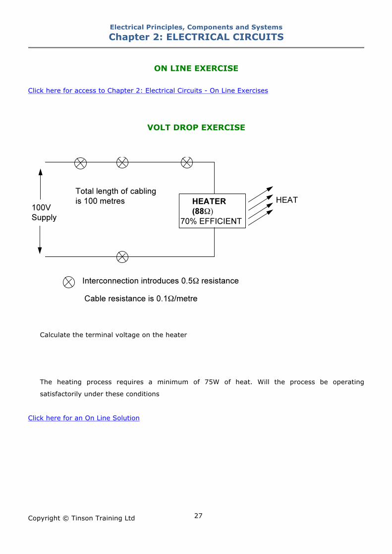
ON LINE EXERCISE
Click here for access to Chapter 2: Electrical Circuits - On Line Exercises
VOLT DROP EXERCISE
Calculate the terminal voltage on the heater
The heating process requires a minimum of 75W of heat. Will the process be operating
satisfactorily under these conditions
Click here for an On Line Solution
Electrical Principles, Components and Systems Chapter 3: DC SUPPLIES
Copyright © Tinson Training Ltd
28
Chapter 3
DC Supplies At the end of this section you will have an understanding of • Dry and wet cells • Electronic DC power supply units
Electrical Principles, Components and Systems Chapter 3: DC SUPPLIES
Copyright © Tinson Training Ltd
29
DC Supplies
A DC supply is one in which the polarity of the supply does not change. It will have a positive and a
negative line and the polarity of connection will in many instances be very important. A DC supply
will essentially be generated from two different sources
• a battery
• a mains power supply unit
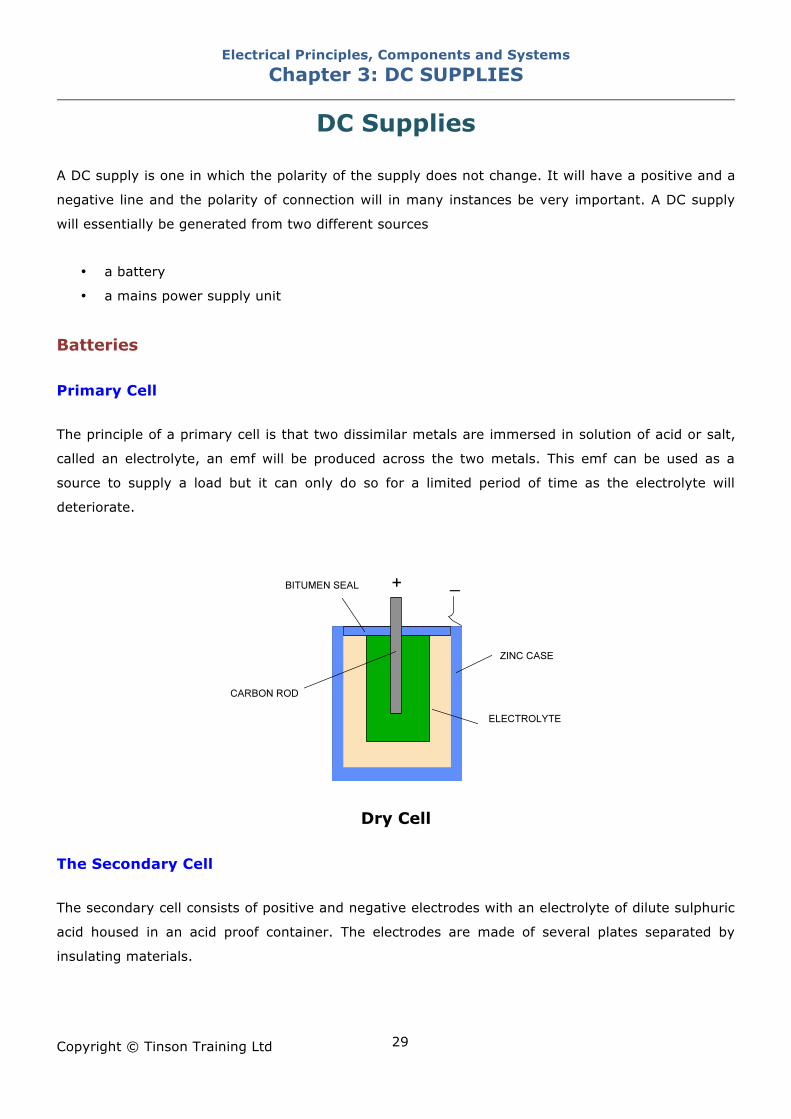
Batteries Primary Cell The principle of a primary cell is that two dissimilar metals are immersed in solution of acid or salt,
called an electrolyte, an emf will be produced across the two metals. This emf can be used as a
source to supply a load but it can only do so for a limited period of time as the electrolyte will
deteriorate.
Dry Cell
The Secondary Cell The secondary cell consists of positive and negative electrodes with an electrolyte of dilute sulphuric
acid housed in an acid proof container. The electrodes are made of several plates separated by
insulating materials.
Electrical Principles, Components and Systems Chapter 3: DC SUPPLIES
Copyright © Tinson Training Ltd
30
When an external load is connected to the terminals of the cells, electrical energy is delivered to the
load. During this discharge period, a chemical reaction takes place and a layer of lead sulphate is
deposited on the plates. This process successively weakens the electrolyte until the cell is unable to
deliver any more energy.
If a DC supply is then connected to the cell terminals and a current passed through it, the lead
sulphate is converted back to sulphuric acid and restores the cell to it’s original position. This
process is known as recharging.
Care and Maintenance of secondary Cells When the chemicals of a cell have changed to the inactive form, they can be made active again by
passing a charging current through the battery in the opposite direction to the discharge current.
There are two methods of charging:
Constant
voltage
charging
A constant voltage is applied to the battery under charge. While the battery is
charging, a steady increase occurs in the terminal voltage, so that the charging
current tapers off to a lower value at the end of the charge compared to the
beginning. It is recommended that lead acid batteries are not charged in this way
and a constant charge rate is better.
Constant
current
charging
This system uses an adjustable voltage source or a variable resistance so that the
charging current can be kept constant throughout the charge.
Charging and maintenance requirements of lead acid and alkaline cells are quite different.
Lead-acid cells These cells are the most widely used due to their comparatively low cost and higher voltage per cell.
They consist of two plates of lead in a electrolyte solution of dilute sulphuric acid. They can be
damaged by charging or discharging too quickly, overcharging and leaving in the discharged state.
Healthy cells can only be maintained in condition either by keeping them fully charged or by
periodically charging them. A lead acid cell will lose it’s charge if left standing over a period of a few
months. The constant current method of charging is preferred and the value of current would vary
with the type of cell. A common value is one-tenth of the ampere-hour capacity. It is important not
to overcharge.
Electrical Principles, Components and Systems Chapter 3: DC SUPPLIES
Copyright © Tinson Training Ltd
31
There are three methods by which the state of charge can be determined.
Colour of plates Fully charged cells should have clear light-grey negative plates and rich brown
positive plates
Terminal voltage Open circuit voltage of a fully charged cell depends on the type, being from
2.1V to 2.3V
Specific gravity This is the best method of determining the state of charge
Provided the lead acid cell is maintained regularly it will last for a long period. Weekly checks on it’s
condition are recommended.
Electrolyte Level The level of the electrolyte should never be allowed to fall below the tops of the plates.
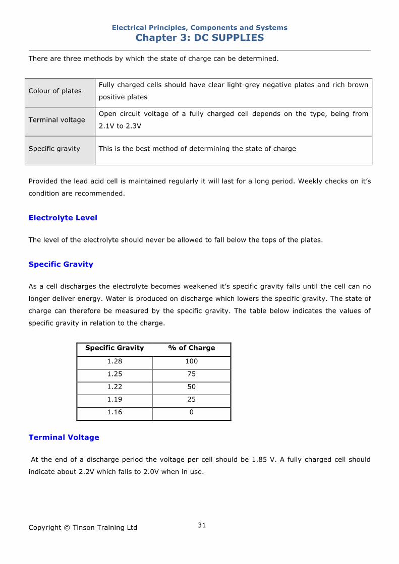
Specific Gravity As a cell discharges the electrolyte becomes weakened it’s specific gravity falls until the cell can no
longer deliver energy. Water is produced on discharge which lowers the specific gravity. The state of
charge can therefore be measured by the specific gravity. The table below indicates the values of
specific gravity in relation to the charge.
Specific Gravity % of Charge
1.28 100
1.25 75
1.22 50
1.19 25
1.16 0
Terminal Voltage At the end of a discharge period the voltage per cell should be 1.85 V. A fully charged cell should
indicate about 2.2V which falls to 2.0V when in use.
Electrical Principles, Components and Systems Chapter 3: DC SUPPLIES
Copyright © Tinson Training Ltd
32
Cell Capacity The capacity of a cell is quoted in ampere - hours. If a cell is capable of delivering 10A for 10 hours
it will have a capacity of 100 ampere hours (Ah). If the current drawn from the cell is more than 10A
it will supply this for less time.
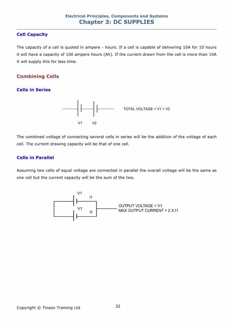
Combining Cells Cells in Series
The combined voltage of connecting several cells in series will be the addition of the voltage of each
cell. The current drawing capacity will be that of one cell.
Cells in Parallel Assuming two cells of equal voltage are connected in parallel the overall voltage will be the same as
one cell but the current capacity will be the sum of the two.

Electrical Principles, Components and Systems Chapter 3: DC SUPPLIES
Copyright © Tinson Training Ltd
33
Linear DC Power Supply Unit
Power Supply Unit
The power input is from a single phase supply which is fused for protection purposes. The AC input
is reduced to an appropriate level by a step down transformer. The output from the transformer
supplies a bridge rectifier. The diodes in this circuit only allow current to pass in one direction.
Consequently the output is unipolar i.e. DC. Fuses are often placed in the DC supply line to protect
the circuitry being supplied.
Smoothing and Regulation The DC output from this circuit will be poor in terms of it’s smoothness and it’s ability to remain
constant regardless of the current being supplied. The following circuits would be added to the
above circuit to create a more useful DC supply
Smoothing
This would remove any ripples of the AC that comes through to the DC.
Regulation
Ensuring that the output voltage remains constant regardless of the load. High current drawn
would have a tendency to lower the output voltage whereas lower currents would have a
tendency to increase the output voltage. Good regulation prevents this occurring.
Current Limit Power supplies will often have a current limit which prevents the output current from increasing
beyond a set limit. This will give protection against short circuits on the output.
Electrical Principles, Components and Systems Chapter 3: DC SUPPLIES
Copyright © Tinson Training Ltd
34
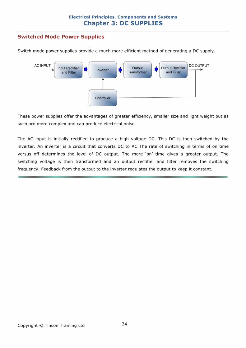
Switched Mode Power Supplies
Switch mode power supplies provide a much more efficient method of generating a DC supply.
These power supplies offer the advantages of greater efficiency, smaller size and light weight but as
such are more complex and can produce electrical noise.
The AC input is initially rectified to produce a high voltage DC. This DC is then switched by the
inverter. An inverter is a circuit that converts DC to AC The rate of switching in terms of on time
versus off determines the level of DC output. The more ‘on’ time gives a greater output. The
switching voltage is then transformed and an output rectifier and filter removes the switching
frequency. Feedback from the output to the inverter regulates the output to keep it constant.
Electrical Principles, Components and Systems Chapter 3: DC SUPPLIES
Copyright © Tinson Training Ltd
35
ON LINE EXERCISE
Click here to access Chapter 3: DC Supplies On Line Exercises
Electrical Principles, Components and Systems Chapter 4: AC SUPPLIES
Copyright © Tinson Training Ltd
36
Chapter 4
AC Supplies At the end of this section you will have an understanding of • how AC is generated • how ac is measured • phase and phase difference • inductance • capacitance
Electrical Principles, Components and Systems Chapter 4: AC SUPPLIES
Copyright © Tinson Training Ltd
37
AC Supplies Generation Definition: emf - electromotive force – the force that makes electrons move
Faradays laws of electromagnetic induction says that if a conductor is moved within a magnetic field
in such a way that it cuts across the lines of magnetic flux, then an emf (electro motive force) will
be induced in that conductor. This emf is more commonly referred to as voltage. The maximum
voltage will be induced when the conductor moves at right angles to the field. If the conductor
moves along the field from pole to pole then no voltage will be induced. The polarity of the voltage
will be determined by the direction of movement. If that conductor is connected to complete a circuit
then current will flow. This is the principle of generation of electricity. A conductor is arranged to
move within a magnetic field and the ends of the conductor form the output from which the power is
delivered. Generators producing AC will be referred to as Alternators
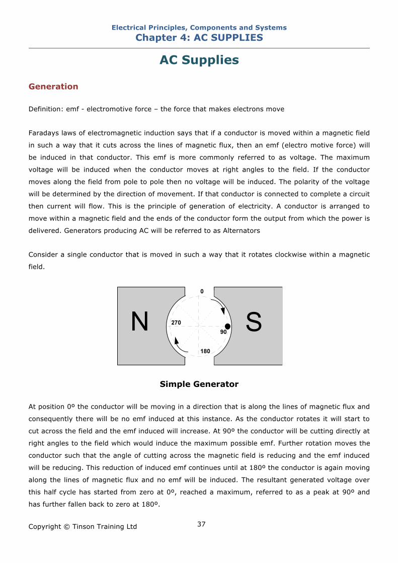
Consider a single conductor that is moved in such a way that it rotates clockwise within a magnetic
field.
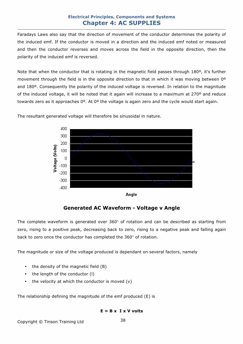
Simple Generator At position 0º the conductor will be moving in a direction that is along the lines of magnetic flux and
consequently there will be no emf induced at this instance. As the conductor rotates it will start to
cut across the field and the emf induced will increase. At 90º the conductor will be cutting directly at
right angles to the field which would induce the maximum possible emf. Further rotation moves the
conductor such that the angle of cutting across the magnetic field is reducing and the emf induced
will be reducing. This reduction of induced emf continues until at 180º the conductor is again moving
along the lines of magnetic flux and no emf will be induced. The resultant generated voltage over
this half cycle has started from zero at 0º, reached a maximum, referred to as a peak at 90º and
has further fallen back to zero at 180º.
Electrical Principles, Components and Systems Chapter 4: AC SUPPLIES
Copyright © Tinson Training Ltd
38
Faradays Laws also say that the direction of movement of the conductor determines the polarity of
the induced emf. If the conductor is moved in a direction and the induced emf noted or measured
and then the conductor reverses and moves across the field in the opposite direction, then the
polarity of the induced emf is reversed.
Note that when the conductor that is rotating in the magnetic field passes through 180º, it’s further
movement through the field is in the opposite direction to that in which it was moving between 0º
and 180º. Consequently the polarity of the induced voltage is reversed. In relation to the magnitude
of the induced voltage, it will be noted that it again will increase to a maximum at 270º and reduce
towards zero as it approaches 0º. At 0º the voltage is again zero and the cycle would start again.
The resultant generated voltage will therefore be sinusoidal in nature.
Generated AC Waveform - Voltage v Angle
The complete waveform is generated over 360° of rotation and can be described as starting from
zero, rising to a positive peak, decreasing back to zero, rising to a negative peak and falling again
back to zero once the conductor has completed the 360° of rotation.
The magnitude or size of the voltage produced is dependant on several factors, namely
• the density of the magnetic field (B)
• the length of the conductor (l)
• the velocity at which the conductor is moved (v)
The relationship defining the magnitude of the emf produced (E) is
E = B x I x V volts
Electrical Principles, Components and Systems Chapter 4: AC SUPPLIES
Copyright © Tinson Training Ltd
39
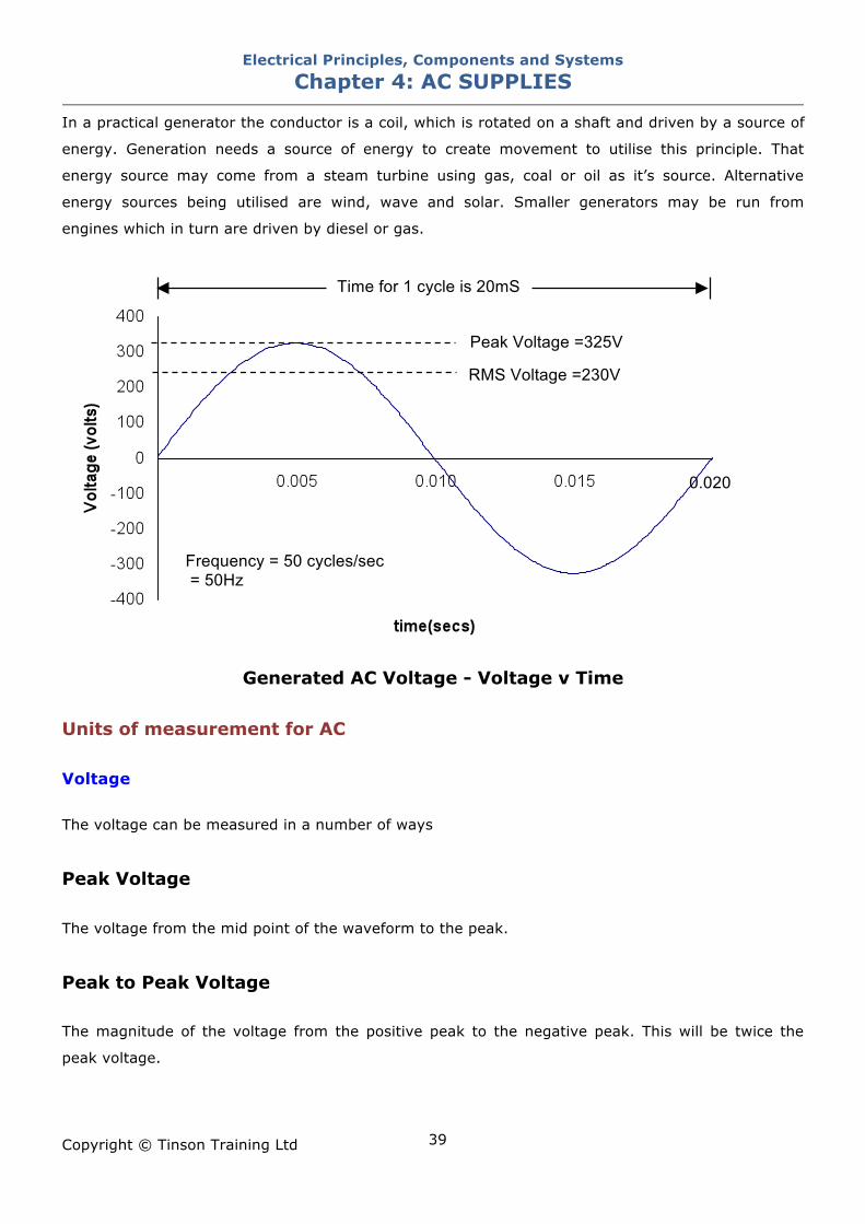
In a practical generator the conductor is a coil, which is rotated on a shaft and driven by a source of
energy. Generation needs a source of energy to create movement to utilise this principle. That
energy source may come from a steam turbine using gas, coal or oil as it’s source. Alternative
energy sources being utilised are wind, wave and solar. Smaller generators may be run from
engines which in turn are driven by diesel or gas.
Generated AC Voltage - Voltage v Time Units of measurement for AC Voltage The voltage can be measured in a number of ways
Peak Voltage
The voltage from the mid point of the waveform to the peak.
Peak to Peak Voltage The magnitude of the voltage from the positive peak to the negative peak. This will be twice the
peak voltage.
0.020
RMS Voltage =230V
Peak Voltage =325V
Time for 1 cycle is 20mS
Frequency = 50 cycles/sec = 50Hz
Electrical Principles, Components and Systems Chapter 4: AC SUPPLIES
Copyright © Tinson Training Ltd
40
RMS Voltage A 10V peak AC voltage would deliver less power than a 10V DC voltage simply because the DC level
is constant at 10V whereas the AC value is not. RMS (Root Mean Square) is a corresponding value of
voltage that would deliver the same power if it were DC. For example a 1.41V peak AC voltage
would deliver the same power as a 1V DC voltage. Therefore the 1.41V AC is quoted as 1V RMS. It’s
value is calculated from
V rms = 0.7071 x Vpeak
Example:
What is the peak value of a 230V RMS voltage
From
V rms = 0.7071 x Vpeak
Vrms V peak =
0.7071
230 V peak =
0.7071 = 325V
All AC values are quoted as RMS and meters will all read RMS. This applies to currents and voltages
and calculations would be carried out in the normal manner using RMS values.
Frequency The time that it takes the voltage to pass through one complete wavelength is determined by the
angular speed at which the conductor is being rotated (the angular speed of the generator). Clearly
the faster the generator turns the less time the waveform will take to go through one cycle. This
property of an AC waveform is referred to as it’s frequency and is quoted as the number of cycles
that the waveform will go through in a second. Frequency is measured in Hertz (Hz). In the UK the
frequency of the generated mains is 50Hz.
Electrical Principles, Components and Systems Chapter 4: AC SUPPLIES
Copyright © Tinson Training Ltd
41
Period Period or periodic time is the time that it takes for the waveform to go through one cycle. Period is
the reciprocal of frequency.
1
Period = Frequency
Phase The X axis of an AC waveform can be considered as two possibilities. The angular position of the
generator or time. Time on the graph would relate to the speed of rotation of the generator. One
cycle would be 360° but the greater the speed of rotation then the shorter the time for one cycle.
3000 rpm is one cycle in 20mS, 1500rpm would be one cycle in 40mS.
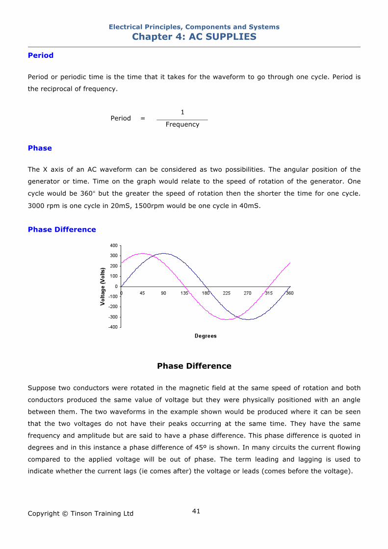
Phase Difference
Phase Difference
Suppose two conductors were rotated in the magnetic field at the same speed of rotation and both
conductors produced the same value of voltage but they were physically positioned with an angle
between them. The two waveforms in the example shown would be produced where it can be seen
that the two voltages do not have their peaks occurring at the same time. They have the same
frequency and amplitude but are said to have a phase difference. This phase difference is quoted in
degrees and in this instance a phase difference of 45º is shown. In many circuits the current flowing
compared to the applied voltage will be out of phase. The term leading and lagging is used to
indicate whether the current lags (ie comes after) the voltage or leads (comes before the voltage).
Electrical Principles, Components and Systems Chapter 4: AC SUPPLIES
Copyright © Tinson Training Ltd
42
Reactive Components There are two other electrical properties that have a particular operation when they are connected to
an ac supply.
Inductance
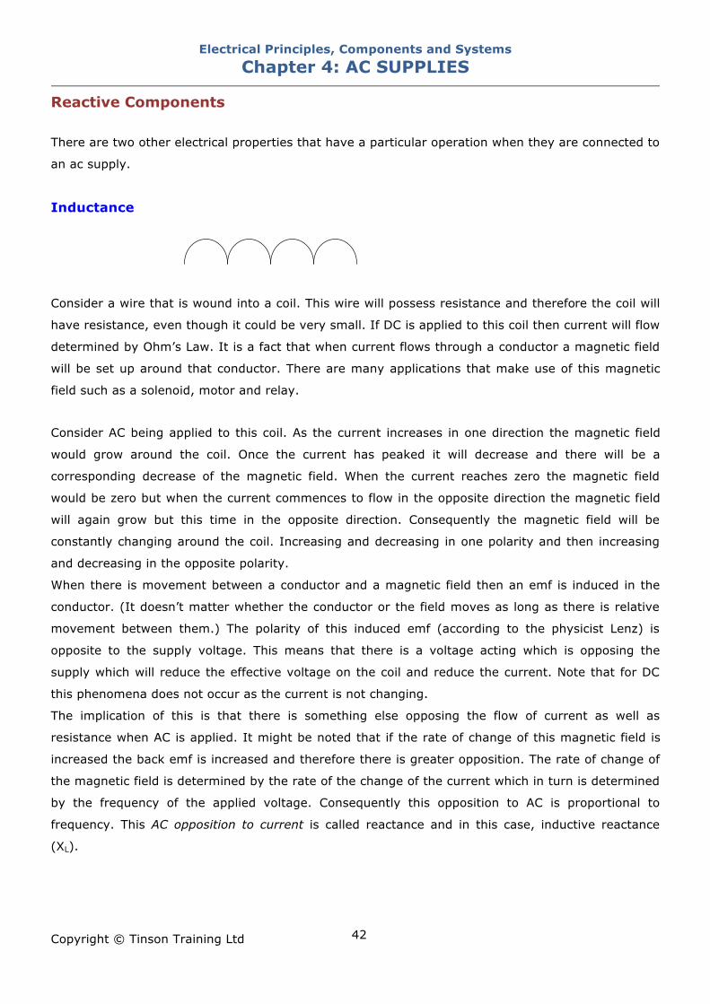
Consider a wire that is wound into a coil. This wire will possess resistance and therefore the coil will
have resistance, even though it could be very small. If DC is applied to this coil then current will flow
determined by Ohm’s Law. It is a fact that when current flows through a conductor a magnetic field
will be set up around that conductor. There are many applications that make use of this magnetic
field such as a solenoid, motor and relay.
Consider AC being applied to this coil. As the current increases in one direction the magnetic field
would grow around the coil. Once the current has peaked it will decrease and there will be a
corresponding decrease of the magnetic field. When the current reaches zero the magnetic field
would be zero but when the current commences to flow in the opposite direction the magnetic field
will again grow but this time in the opposite direction. Consequently the magnetic field will be
constantly changing around the coil. Increasing and decreasing in one polarity and then increasing
and decreasing in the opposite polarity.
When there is movement between a conductor and a magnetic field then an emf is induced in the
conductor. (It doesn’t matter whether the conductor or the field moves as long as there is relative
movement between them.) The polarity of this induced emf (according to the physicist Lenz) is
opposite to the supply voltage. This means that there is a voltage acting which is opposing the
supply which will reduce the effective voltage on the coil and reduce the current. Note that for DC
this phenomena does not occur as the current is not changing.
The implication of this is that there is something else opposing the flow of current as well as
resistance when AC is applied. It might be noted that if the rate of change of this magnetic field is
increased the back emf is increased and therefore there is greater opposition. The rate of change of
the magnetic field is determined by the rate of the change of the current which in turn is determined
by the frequency of the applied voltage. Consequently this opposition to AC is proportional to
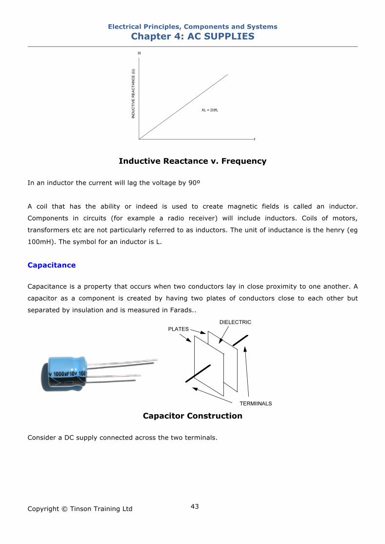
frequency. This AC opposition to current is called reactance and in this case, inductive reactance
(XL).
Electrical Principles, Components and Systems Chapter 4: AC SUPPLIES
Copyright © Tinson Training Ltd
43
Inductive Reactance v. Frequency In an inductor the current will lag the voltage by 90º
A coil that has the ability or indeed is used to create magnetic fields is called an inductor.
Components in circuits (for example a radio receiver) will include inductors. Coils of motors,
transformers etc are not particularly referred to as inductors. The unit of inductance is the henry (eg
100mH). The symbol for an inductor is L.
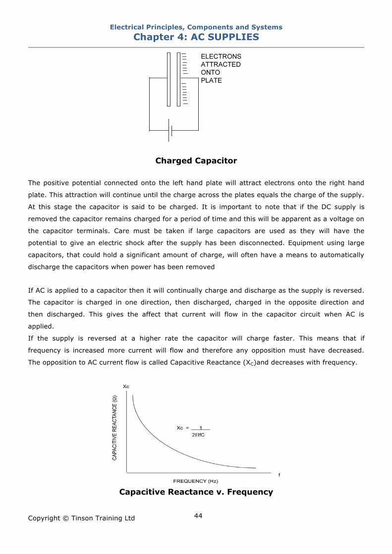
Capacitance Capacitance is a property that occurs when two conductors lay in close proximity to one another. A
capacitor as a component is created by having two plates of conductors close to each other but
separated by insulation and is measured in Farads..
Capacitor Construction
Consider a DC supply connected across the two terminals.
Electrical Principles, Components and Systems Chapter 4: AC SUPPLIES
Copyright © Tinson Training Ltd
44
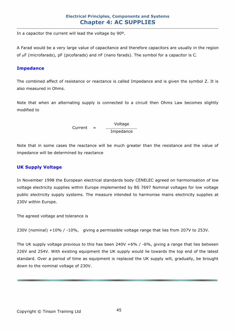
Charged Capacitor
The positive potential connected onto the left hand plate will attract electrons onto the right hand
plate. This attraction will continue until the charge across the plates equals the charge of the supply.
At this stage the capacitor is said to be charged. It is important to note that if the DC supply is
removed the capacitor remains charged for a period of time and this will be apparent as a voltage on
the capacitor terminals. Care must be taken if large capacitors are used as they will have the
potential to give an electric shock after the supply has been disconnected. Equipment using large
capacitors, that could hold a significant amount of charge, will often have a means to automatically
discharge the capacitors when power has been removed
If AC is applied to a capacitor then it will continually charge and discharge as the supply is reversed.
The capacitor is charged in one direction, then discharged, charged in the opposite direction and
then discharged. This gives the affect that current will flow in the capacitor circuit when AC is
applied.
If the supply is reversed at a higher rate the capacitor will charge faster. This means that if
frequency is increased more current will flow and therefore any opposition must have decreased.
The opposition to AC current flow is called Capacitive Reactance (XC)and decreases with frequency.
Capacitive Reactance v. Frequency
Electrical Principles, Components and Systems Chapter 4: AC SUPPLIES
Copyright © Tinson Training Ltd
45
In a capacitor the current will lead the voltage by 90º.
A Farad would be a very large value of capacitance and therefore capacitors are usually in the region
of µF (microfarads), pF (picofarads) and nF (nano farads). The symbol for a capacitor is C.
Impedance The combined affect of resistance or reactance is called Impedance and is given the symbol Z. It is
also measured in Ohms.
Note that when an alternating supply is connected to a circuit then Ohms Law becomes slightly
modified to
Voltage
Current = Impedance
Note that in some cases the reactance will be much greater than the resistance and the value of
impedance will be determined by reactance
UK Supply Voltage In November 1998 the European electrical standards body CENELEC agreed on harmonisation of low
voltage electricity supplies within Europe implemented by BS 7697 Nominal voltages for low voltage
public electricity supply systems. The measure intended to harmonise mains electricity supplies at
230V within Europe.
The agreed voltage and tolerance is
230V (nominal) +10% / -10%, giving a permissible voltage range that lies from 207V to 253V.
The UK supply voltage previous to this has been 240V +6% / -6%, giving a range that lies between
226V and 254V. With existing equipment the UK supply would lie towards the top end of the latest
standard. Over a period of time as equipment is replaced the UK supply will, gradually, be brought
down to the nominal voltage of 230V.
Electrical Principles, Components and Systems Chapter 4: AC SUPPLIES
Copyright © Tinson Training Ltd
46
ON LINE EXERCISE
Click here to access Chapter 4 : AC Supplies - On Line Exercises
Electrical Principles, Components and Systems Chapter 5: THREE PHASE SUPPLIES
Copyright © Tinson Training Ltd
47
Chapter 5
Three Phase Supplies At the end of this section you will have an understanding of • how three phase supplies are generated • the voltages present in a three phase system • how single phase supplies are produced from a three phase supply
Electrical Principles, Components and Systems Chapter 5: THREE PHASE SUPPLIES
Copyright © Tinson Training Ltd
48
Three Phase Alternating Supplies
Generation
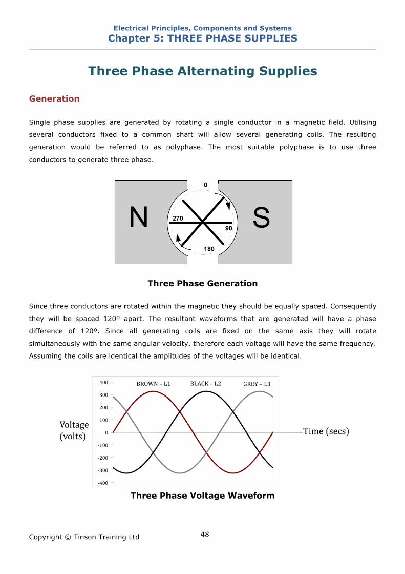
Single phase supplies are generated by rotating a single conductor in a magnetic field. Utilising
several conductors fixed to a common shaft will allow several generating coils. The resulting
generation would be referred to as polyphase. The most suitable polyphase is to use three
conductors to generate three phase.
Three Phase Generation
Since three conductors are rotated within the magnetic they should be equally spaced. Consequently
they will be spaced 120º apart. The resultant waveforms that are generated will have a phase
difference of 120º. Since all generating coils are fixed on the same axis they will rotate
simultaneously with the same angular velocity, therefore each voltage will have the same frequency.
Assuming the coils are identical the amplitudes of the voltages will be identical.
Three Phase Voltage Waveform
Electrical Principles, Components and Systems Chapter 5: THREE PHASE SUPPLIES
Copyright © Tinson Training Ltd
49
Whilst generators could be many phase, three is the optimum and the one that is used.. Within
Europe the three phases are identified as Brown, Black and Grey in that order of phase rotation. The
alphanumeric identifiers for the three phases is L1, L2 and L3.
Distribution The three phase generated at the power station by a generator in the UK will be about 15000V. This
will be transformed up for distribution to 133kV or 400kV. A transformer is used for this process
which is a device that will increase or decrease the voltage of an AC supply. The transformer will not
change power but simply change the level of the voltage. The high voltage is distributed across the
country by pylons and cables through the National Grid. This voltage is transformed back down first
to 33KV and then to 11KV. Industrial premises will receive this 33KV or 11KV as their incoming
supply. This is then further transformed down to 230V for use on the factory floor.
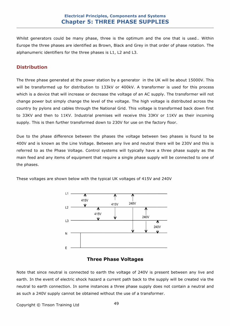
Due to the phase difference between the phases the voltage between two phases is found to be
400V and is known as the Line Voltage. Between any live and neutral there will be 230V and this is
referred to as the Phase Voltage. Control systems will typically have a three phase supply as the
main feed and any items of equipment that require a single phase supply will be connected to one of
the phases.
These voltages are shown below with the typical UK voltages of 415V and 240V
Three Phase Voltages
Note that since neutral is connected to earth the voltage of 240V is present between any live and
earth. In the event of electric shock hazard a current path back to the supply will be created via the
neutral to earth connection. In some instances a three phase supply does not contain a neutral and
as such a 240V supply cannot be obtained without the use of a transformer.
Electrical Principles, Components and Systems Chapter 5: THREE PHASE SUPPLIES
Copyright © Tinson Training Ltd
50
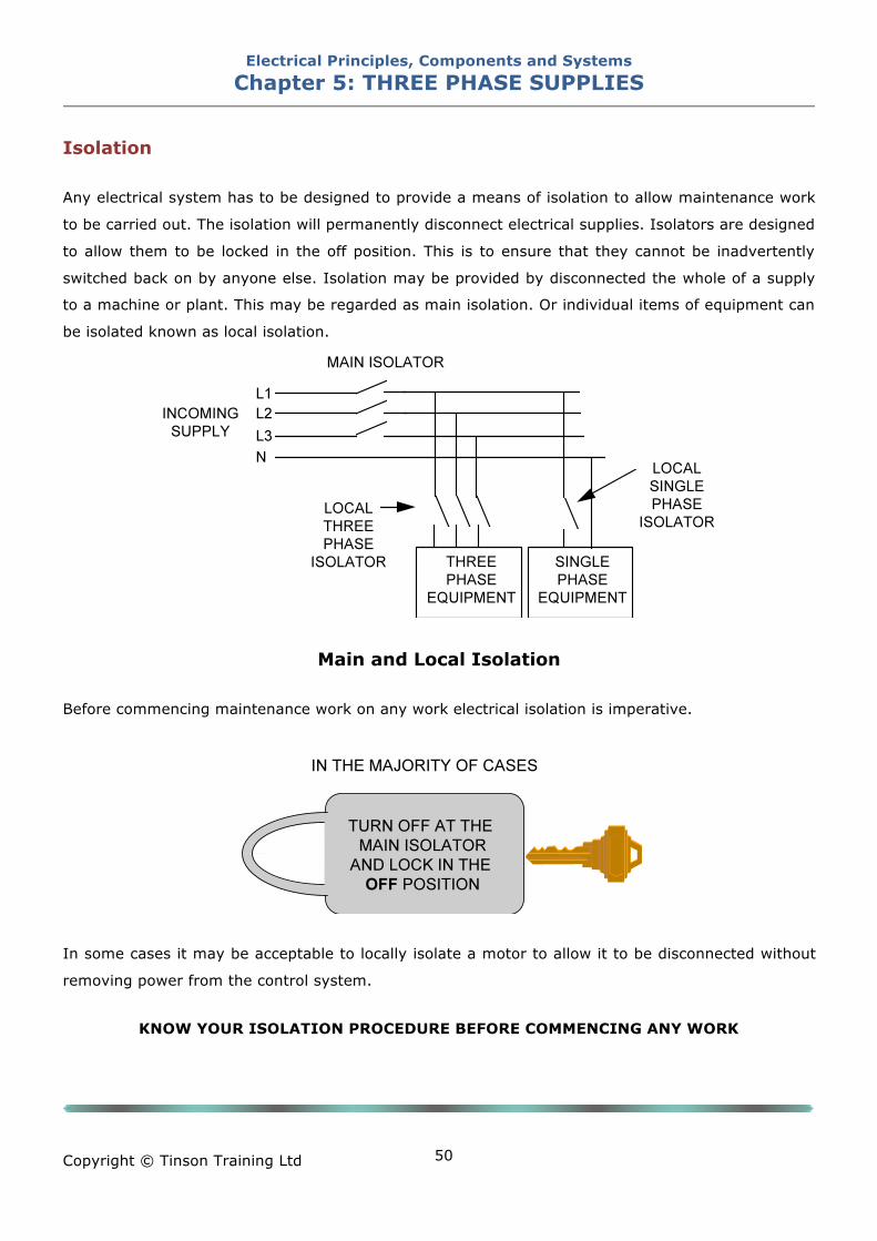
Isolation Any electrical system has to be designed to provide a means of isolation to allow maintenance work
to be carried out. The isolation will permanently disconnect electrical supplies. Isolators are designed
to allow them to be locked in the off position. This is to ensure that they cannot be inadvertently
switched back on by anyone else. Isolation may be provided by disconnected the whole of a supply
to a machine or plant. This may be regarded as main isolation. Or individual items of equipment can
be isolated known as local isolation.
Main and Local Isolation Before commencing maintenance work on any work electrical isolation is imperative.
In some cases it may be acceptable to locally isolate a motor to allow it to be disconnected without
removing power from the control system.
KNOW YOUR ISOLATION PROCEDURE BEFORE COMMENCING ANY WORK
Electrical Principles, Components and Systems Chapter 5: THREE PHASE SUPPLIES
Copyright © Tinson Training Ltd
51
ON LINE EXERCISE
Click here to access Chapter 5: Three Phase Supplies - On Line Exercises
Electrical Principles, Components and Systems Chapter 6: TRANSFORMERS
Copyright © Tinson Training Ltd
52
Chapter 6
Transformers At the end of this section you will have an understanding of • the principle of operation of a transformer • how the output voltage relates to the secondary • how transformers are connected • centre tapped transformers
Electrical Principles, Components and Systems Chapter 6: TRANSFORMERS
Copyright © Tinson Training Ltd
53
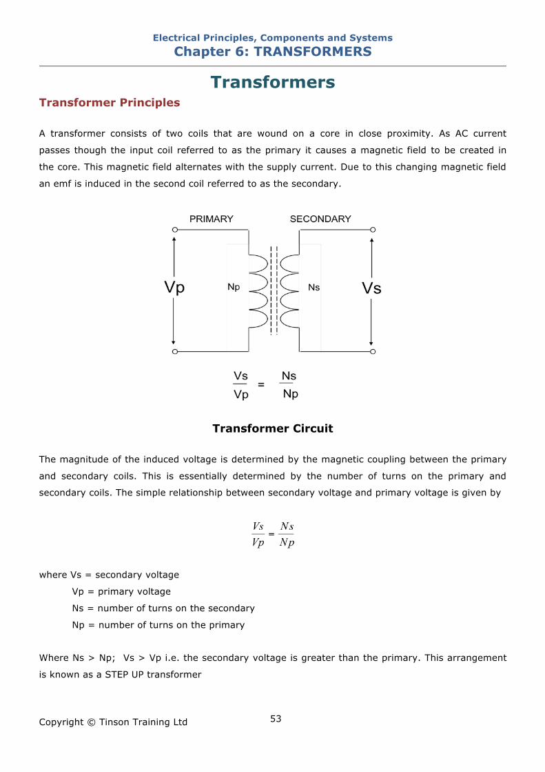
Transformers Transformer Principles A transformer consists of two coils that are wound on a core in close proximity. As AC current
passes though the input coil referred to as the primary it causes a magnetic field to be created in
the core. This magnetic field alternates with the supply current. Due to this changing magnetic field
an emf is induced in the second coil referred to as the secondary.
Transformer Circuit
The magnitude of the induced voltage is determined by the magnetic coupling between the primary
and secondary coils. This is essentially determined by the number of turns on the primary and
secondary coils. The simple relationship between secondary voltage and primary voltage is given by
where Vs = secondary voltage
Vp = primary voltage
Ns = number of turns on the secondary
Np = number of turns on the primary
Where Ns > Np; Vs > Vp i.e. the secondary voltage is greater than the primary. This arrangement
is known as a STEP UP transformer
Electrical Principles, Components and Systems Chapter 6: TRANSFORMERS
Copyright © Tinson Training Ltd
54
Where Ns < Np; Vs < Vp i.e. the secondary voltage is less than the primary. This arrangement is
known as a STEP DOWN transformer.
Where Ns = Np; Vs = Vp; the primary and secondary voltages are equal. In this arrangement the
transformer is used to provide electrical isolation between primary and secondary. This may be
known as an ISOLATION transformer.
It is important to appreciate that the transformer cannot magnify power. In an ideal transformer the
power in the primary circuit is equal to the power in the secondary circuit. Efficiency is the measure
of the power output from the transformer compared to the power input.
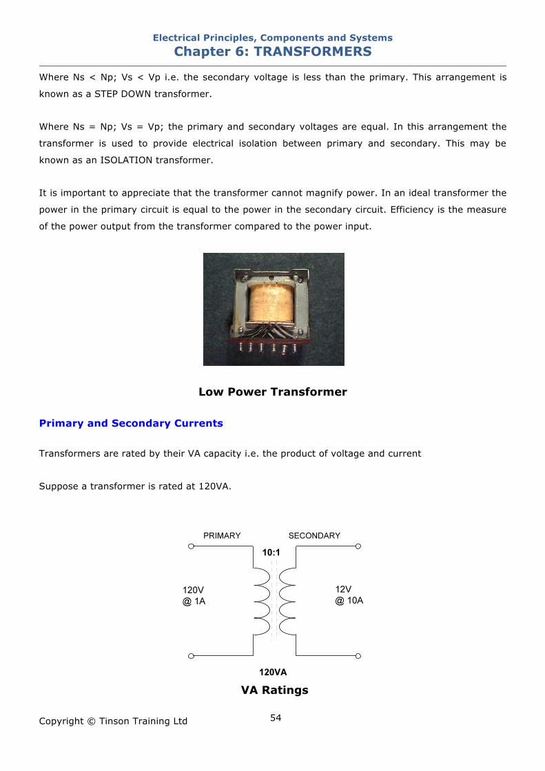
Low Power Transformer Primary and Secondary Currents Transformers are rated by their VA capacity i.e. the product of voltage and current
Suppose a transformer is rated at 120VA.
VA Ratings
Electrical Principles, Components and Systems Chapter 6: TRANSFORMERS
Copyright © Tinson Training Ltd
55
If the primary voltage was 120 Volts, the 120VA power rating would limit the input current to 1A.
The transformer being a 10:1 step down type, would give an output voltage of 12 Volts. The VA
rating at the secondary being 120 VA would restrict the output current to 10A. Currents greater than
this would create an overload. By a similar calculation it can be appreciated that a step up
transformer would allow less secondary current than primary current.
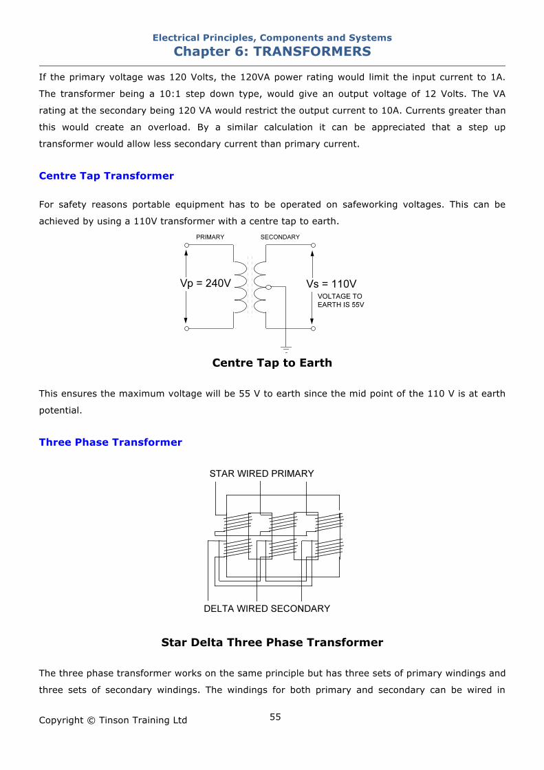
Centre Tap Transformer For safety reasons portable equipment has to be operated on safeworking voltages. This can be
achieved by using a 110V transformer with a centre tap to earth.
Centre Tap to Earth
This ensures the maximum voltage will be 55 V to earth since the mid point of the 110 V is at earth
potential.
Three Phase Transformer
Star Delta Three Phase Transformer
The three phase transformer works on the same principle but has three sets of primary windings and
three sets of secondary windings. The windings for both primary and secondary can be wired in
Electrical Principles, Components and Systems Chapter 6: TRANSFORMERS
Copyright © Tinson Training Ltd
56
either star or delta to suit the application. Consequently star-star, star-delta, delta-star and delta-
delta configurations are possible.
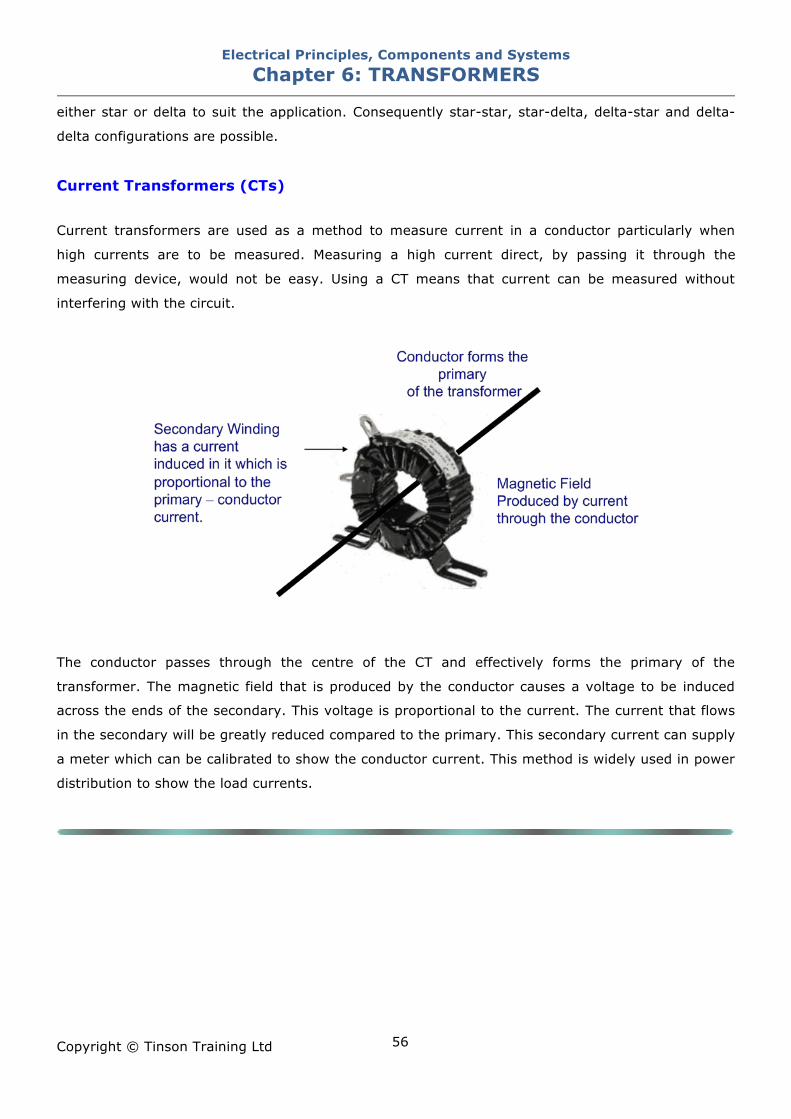
Current Transformers (CTs)
Current transformers are used as a method to measure current in a conductor particularly when
high currents are to be measured. Measuring a high current direct, by passing it through the
measuring device, would not be easy. Using a CT means that current can be measured without
interfering with the circuit.
The conductor passes through the centre of the CT and effectively forms the primary of the
transformer. The magnetic field that is produced by the conductor causes a voltage to be induced
across the ends of the secondary. This voltage is proportional to the current. The current that flows
in the secondary will be greatly reduced compared to the primary. This secondary current can supply
a meter which can be calibrated to show the conductor current. This method is widely used in power
distribution to show the load currents.
Electrical Principles, Components and Systems Chapter 6: TRANSFORMERS
Copyright © Tinson Training Ltd
57
ON LINE EXERCISE Click here to access Chapter 6: Transformers - On Line Exercises
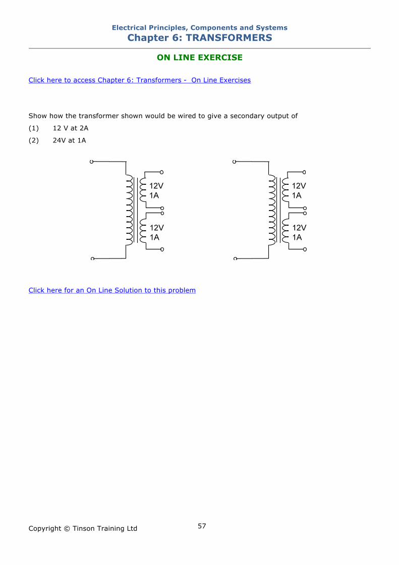
Show how the transformer shown would be wired to give a secondary output of
(1) 12 V at 2A
(2) 24V at 1A
Click here for an On Line Solution to this problem
Electrical Principles, Components and Systems Chapter 7: ELECTRICAL TEST EQUIPMENT
Copyright © Tinson Training Ltd
58
Chapter 7
Electrical Test Equipment At the end of this section you will have an understanding of the operation of
• digital multimeters
• insulation testers
• clip on ammeters
• moving coil meters

Electrical Principles, Components and Systems Chapter 7: ELECTRICAL TEST EQUIPMENT
Copyright © Tinson Training Ltd
59
Electrical Test Equipment
There are several items of test equipment that can be used to carry out tests on electrical
equipment. Those instruments include
• Digital multimeter (DMM)
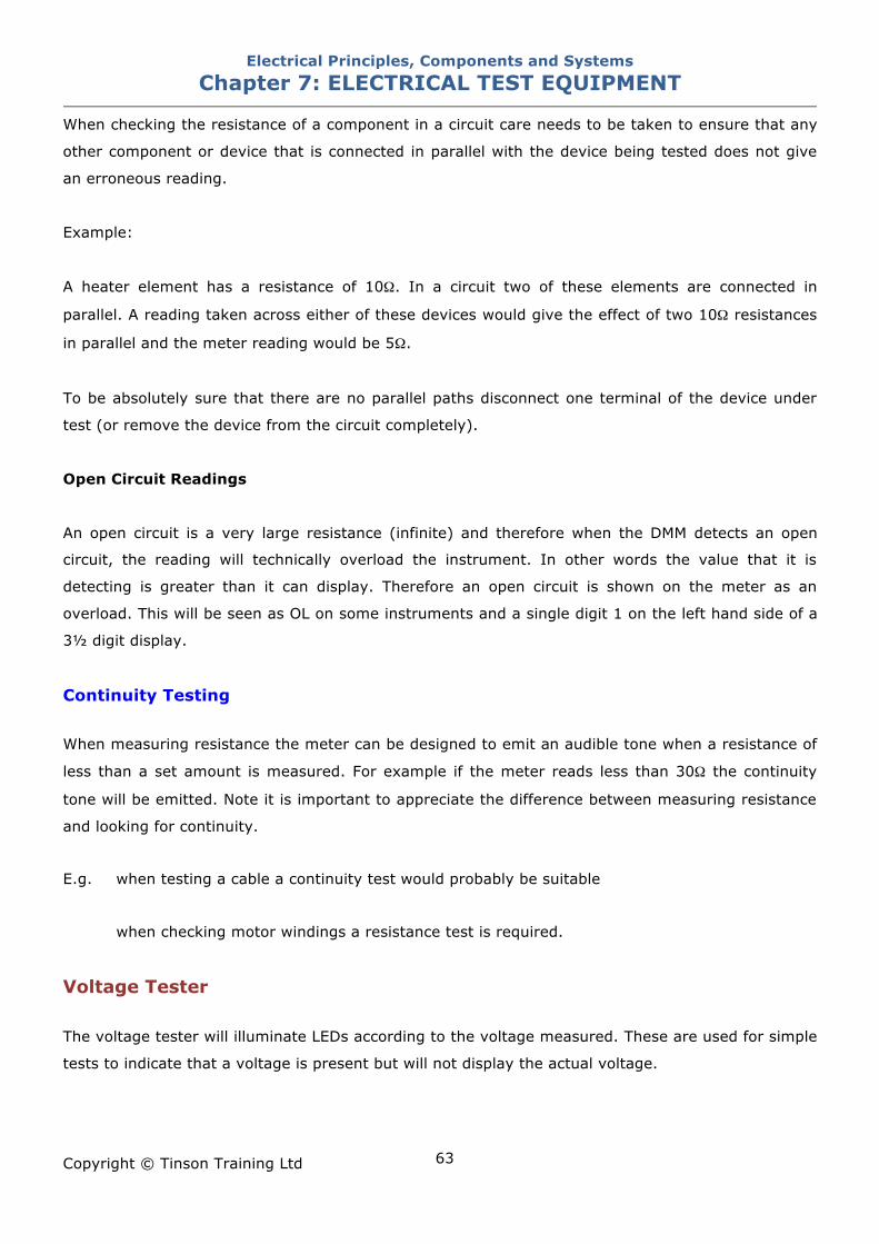
• Voltage Tester
• Clamp Meter
• Insulation Tester (commonly referred to as a megger)
Digital Multimeter
Multi Meter with Range selection Auto Ranging Multimeter
Digital Multimeters (DMM) Probably the most common test instrument to use when carrying out testing or fault finding on
electrical equipment is the digital multimeter (DMM). This meter offers many advantages over its
predecessor the analogue moving coil meter. These advantages include greater accuracy, more
reliability, more robust, will cope with overloads better and will read when meter connections are the
wrong way round.
Electrical Principles, Components and Systems Chapter 7: ELECTRICAL TEST EQUIPMENT
Copyright © Tinson Training Ltd
60
The original AVOMeter took its name from a combined ammeter, voltmeter and ohmmeter. Most
multimeters will at least measure these three quantities but some will have other operations that
will rarely be used by the majority of users. The DMM will typically be used to measure voltage and
resistance and will rarely be used to measure current.
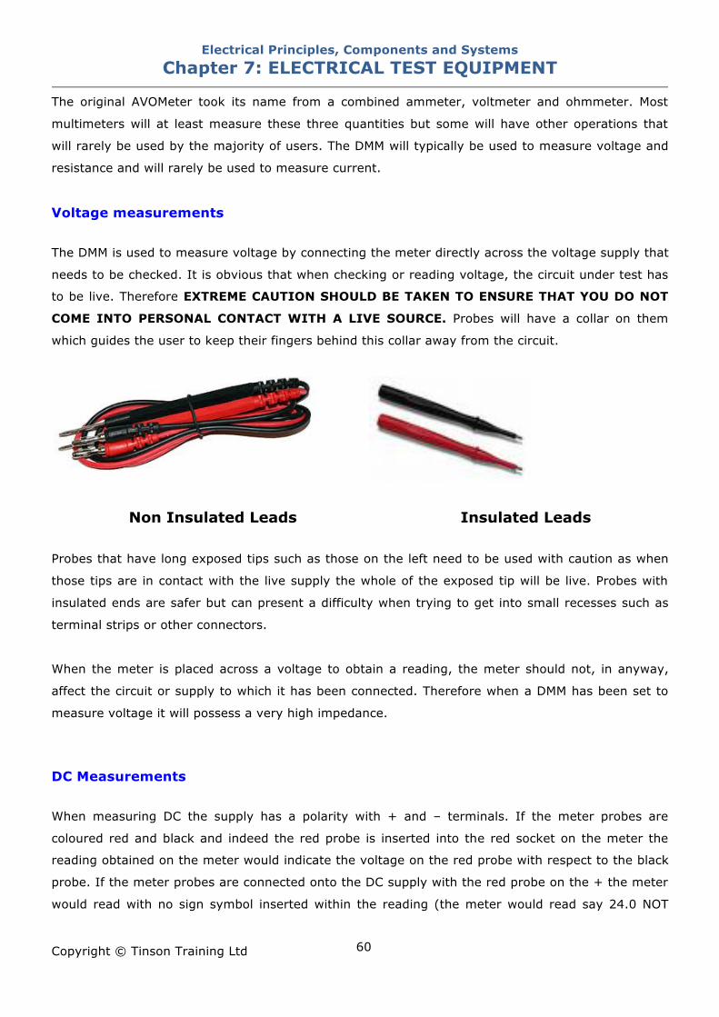
Voltage measurements The DMM is used to measure voltage by connecting the meter directly across the voltage supply that
needs to be checked. It is obvious that when checking or reading voltage, the circuit under test has
to be live. Therefore EXTREME CAUTION SHOULD BE TAKEN TO ENSURE THAT YOU DO NOT
COME INTO PERSONAL CONTACT WITH A LIVE SOURCE. Probes will have a collar on them
which guides the user to keep their fingers behind this collar away from the circuit.
Non Insulated Leads Insulated Leads
Probes that have long exposed tips such as those on the left need to be used with caution as when
those tips are in contact with the live supply the whole of the exposed tip will be live. Probes with
insulated ends are safer but can present a difficulty when trying to get into small recesses such as
terminal strips or other connectors.
When the meter is placed across a voltage to obtain a reading, the meter should not, in anyway,
affect the circuit or supply to which it has been connected. Therefore when a DMM has been set to
measure voltage it will possess a very high impedance.
DC Measurements When measuring DC the supply has a polarity with + and – terminals. If the meter probes are
coloured red and black and indeed the red probe is inserted into the red socket on the meter the
reading obtained on the meter would indicate the voltage on the red probe with respect to the black
probe. If the meter probes are connected onto the DC supply with the red probe on the + the meter
would read with no sign symbol inserted within the reading (the meter would read say 24.0 NOT
Electrical Principles, Components and Systems Chapter 7: ELECTRICAL TEST EQUIPMENT
Copyright © Tinson Training Ltd
61
+24.0). If the red probe is connected onto the – supply the meter would read the value with a –
sign in front of the reading. (eg –24.0V). This would indicate that the red probe was reading less
than the voltage on the black probe. Hopefully the value of voltage read would be the same
whichever way the probes are connected.
AC Measurements When measuring an AC voltage there is no polarity associated with the supply and therefore it does
not matter which way around the meter probes are connected. There will never be a – sign
produced when measuring AC.
AC / DC setting On some instruments it is necessary set the meter to read AC or DC and it is important that this is
done. There is no alternative other than knowing the type of voltage that you should be reading. It
is worthwhile knowing that many instruments will give strange readings if they are set on the wrong
type of voltage to what is being read.
Range setting Some instruments will need to be set on the correct range. The lower the voltage being read the
greater the accuracy of the reading. Eg Voltages in the range of 0 – 9.9 Volts could be read with an
accuracy of say three decimal places, voltages in the range 10.00 – 99.99 could be read with an
accuracy of two decimal places and voltages in the range 100.0 – 999.9 could be read with an
accuracy of 1 decimal place. If the meter is set on a range that is too low for the voltage being read
the meter will be overloaded and will indicate in some that an overload has occurred. Meters will
vary on how they indicate this.
Autosetting / Autoranging
The easiest meter to use that automatically sets to read AC or DC when the probes are touched onto
the circuit (Autosetting) and automatically sets the range to a setting that allows the most accurate
reading (autoranging). Some instruments will also automatically select between voltage and
resistance measurement depending upon whether voltage is detected or not.
Electrical Principles, Components and Systems Chapter 7: ELECTRICAL TEST EQUIPMENT
Copyright © Tinson Training Ltd
62
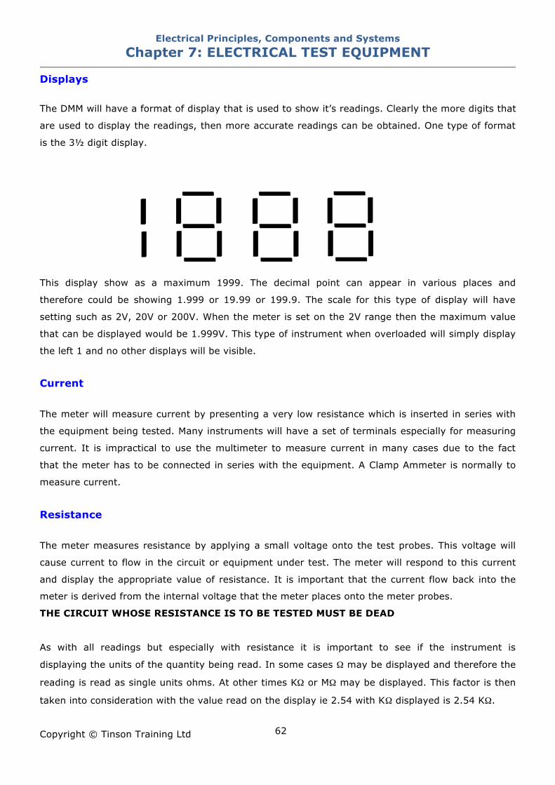
Displays The DMM will have a format of display that is used to show it’s readings. Clearly the more digits that
are used to display the readings, then more accurate readings can be obtained. One type of format
is the 3# digit display.
This display show as a maximum 1999. The decimal point can appear in various places and
therefore could be showing 1.999 or 19.99 or 199.9. The scale for this type of display will have
setting such as 2V, 20V or 200V. When the meter is set on the 2V range then the maximum value
that can be displayed would be 1.999V. This type of instrument when overloaded will simply display
the left 1 and no other displays will be visible.
Current The meter will measure current by presenting a very low resistance which is inserted in series with
the equipment being tested. Many instruments will have a set of terminals especially for measuring
current. It is impractical to use the multimeter to measure current in many cases due to the fact
that the meter has to be connected in series with the equipment. A Clamp Ammeter is normally to
measure current.
Resistance The meter measures resistance by applying a small voltage onto the test probes. This voltage will
cause current to flow in the circuit or equipment under test. The meter will respond to this current
and display the appropriate value of resistance. It is important that the current flow back into the
meter is derived from the internal voltage that the meter places onto the meter probes.
THE CIRCUIT WHOSE RESISTANCE IS TO BE TESTED MUST BE DEAD
As with all readings but especially with resistance it is important to see if the instrument is
displaying the units of the quantity being read. In some cases ! may be displayed and therefore the
reading is read as single units ohms. At other times K! or M! may be displayed. This factor is then
taken into consideration with the value read on the display ie 2.54 with K! displayed is 2.54 K!.
Electrical Principles, Components and Systems Chapter 7: ELECTRICAL TEST EQUIPMENT
Copyright © Tinson Training Ltd
63
When checking the resistance of a component in a circuit care needs to be taken to ensure that any
other component or device that is connected in parallel with the device being tested does not give
an erroneous reading.
Example:
A heater element has a resistance of 10!. In a circuit two of these elements are connected in
parallel. A reading taken across either of these devices would give the effect of two 10! resistances
in parallel and the meter reading would be 5!.
To be absolutely sure that there are no parallel paths disconnect one terminal of the device under
test (or remove the device from the circuit completely).
Open Circuit Readings
An open circuit is a very large resistance (infinite) and therefore when the DMM detects an open
circuit, the reading will technically overload the instrument. In other words the value that it is
detecting is greater than it can display. Therefore an open circuit is shown on the meter as an
overload. This will be seen as OL on some instruments and a single digit 1 on the left hand side of a
3# digit display.
Continuity Testing When measuring resistance the meter can be designed to emit an audible tone when a resistance of
less than a set amount is measured. For example if the meter reads less than 30! the continuity
tone will be emitted. Note it is important to appreciate the difference between measuring resistance
and looking for continuity.
E.g. when testing a cable a continuity test would probably be suitable
when checking motor windings a resistance test is required.
Voltage Tester The voltage tester will illuminate LEDs according to the voltage measured. These are used for simple
tests to indicate that a voltage is present but will not display the actual voltage.
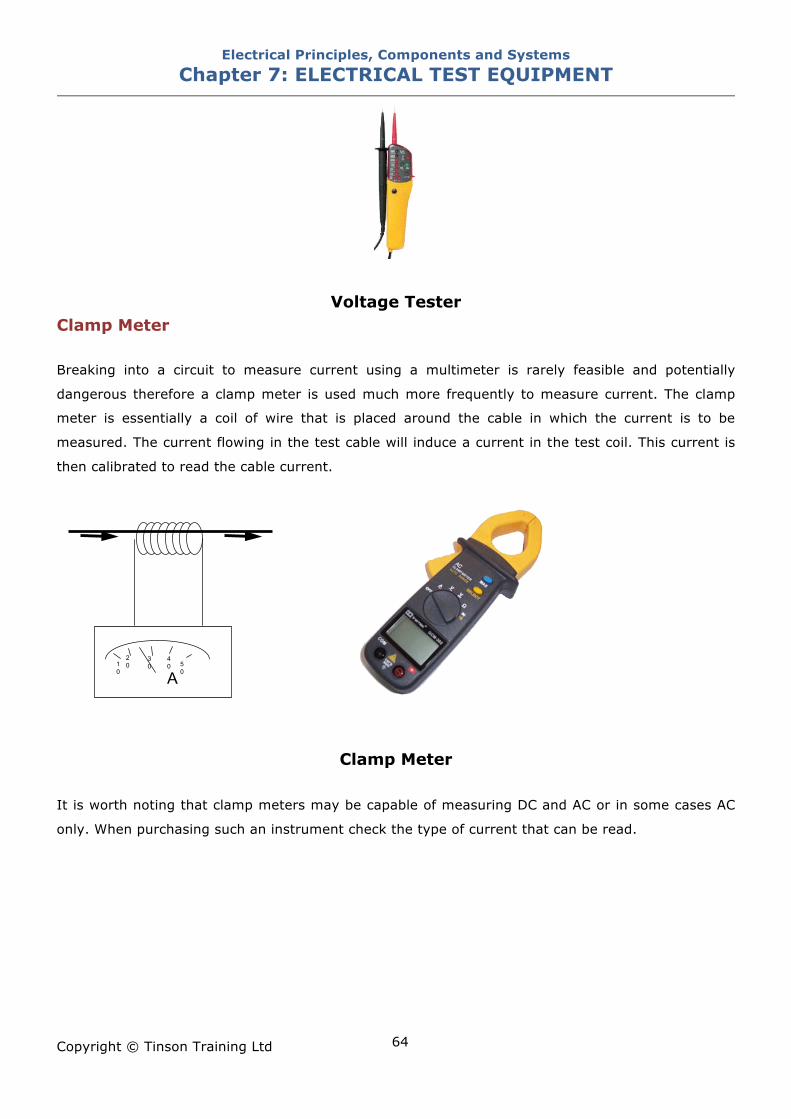
Electrical Principles, Components and Systems Chapter 7: ELECTRICAL TEST EQUIPMENT
Copyright © Tinson Training Ltd
64
Voltage Tester Clamp Meter Breaking into a circuit to measure current using a multimeter is rarely feasible and potentially
dangerous therefore a clamp meter is used much more frequently to measure current. The clamp
meter is essentially a coil of wire that is placed around the cable in which the current is to be
measured. The current flowing in the test cable will induce a current in the test coil. This current is
then calibrated to read the cable current.
Clamp Meter
It is worth noting that clamp meters may be capable of measuring DC and AC or in some cases AC
only. When purchasing such an instrument check the type of current that can be read.
A 10
20 3
0 40 5
0
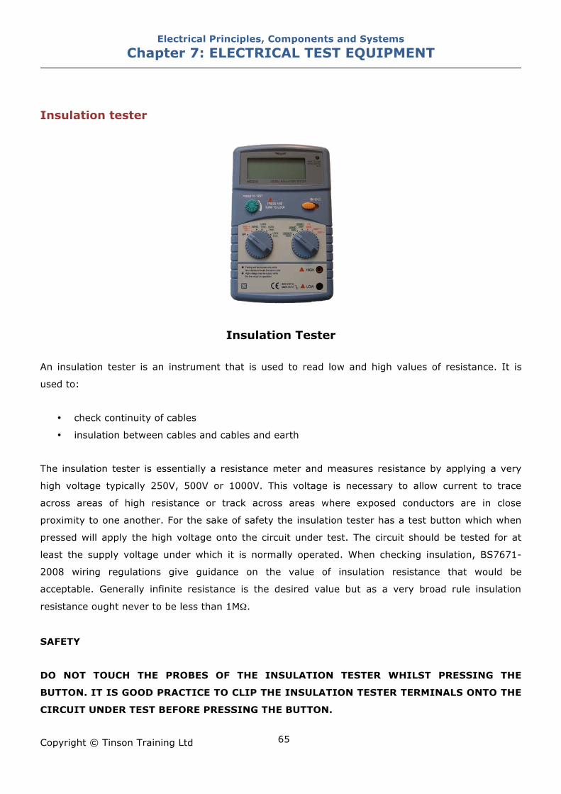
Electrical Principles, Components and Systems Chapter 7: ELECTRICAL TEST EQUIPMENT
Copyright © Tinson Training Ltd
65
Insulation tester
Insulation Tester An insulation tester is an instrument that is used to read low and high values of resistance. It is
used to:
• check continuity of cables
• insulation between cables and cables and earth
The insulation tester is essentially a resistance meter and measures resistance by applying a very
high voltage typically 250V, 500V or 1000V. This voltage is necessary to allow current to trace
across areas of high resistance or track across areas where exposed conductors are in close
proximity to one another. For the sake of safety the insulation tester has a test button which when
pressed will apply the high voltage onto the circuit under test. The circuit should be tested for at
least the supply voltage under which it is normally operated. When checking insulation, BS7671-
2008 wiring regulations give guidance on the value of insulation resistance that would be
acceptable. Generally infinite resistance is the desired value but as a very broad rule insulation
resistance ought never to be less than 1M!.
SAFETY
DO NOT TOUCH THE PROBES OF THE INSULATION TESTER WHILST PRESSING THE
BUTTON. IT IS GOOD PRACTICE TO CLIP THE INSULATION TESTER TERMINALS ONTO THE
CIRCUIT UNDER TEST BEFORE PRESSING THE BUTTON.
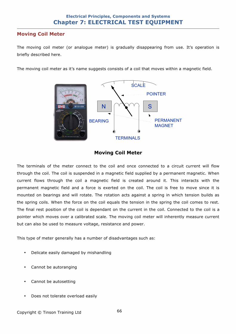
Electrical Principles, Components and Systems Chapter 7: ELECTRICAL TEST EQUIPMENT
Copyright © Tinson Training Ltd
66
Moving Coil Meter The moving coil meter (or analogue meter) is gradually disappearing from use. It’s operation is
briefly described here.
The moving coil meter as it’s name suggests consists of a coil that moves within a magnetic field.
Moving Coil Meter The terminals of the meter connect to the coil and once connected to a circuit current will flow
through the coil. The coil is suspended in a magnetic field supplied by a permanent magnetic. When
current flows through the coil a magnetic field is created around it. This interacts with the
permanent magnetic field and a force is exerted on the coil. The coil is free to move since it is
mounted on bearings and will rotate. The rotation acts against a spring in which tension builds as
the spring coils. When the force on the coil equals the tension in the spring the coil comes to rest.
The final rest position of the coil is dependant on the current in the coil. Connected to the coil is a
pointer which moves over a calibrated scale. The moving coil meter will inherently measure current
but can also be used to measure voltage, resistance and power.
This type of meter generally has a number of disadvantages such as:
• Delicate easily damaged by mishandling
• Cannot be autoranging
• Cannot be autosetting
• Does not tolerate overload easily
Electrical Principles, Components and Systems Chapter 7: ELECTRICAL TEST EQUIPMENT
Copyright © Tinson Training Ltd
67
Key Points when using a Multi Meter
Ensure that the leads are in good condition – no damage to the insulation or connectors.
Ensure that the leads are operational – put the instrument on continuity and touch the
probes together. The audible tone indicates the leads are working.
Check that the instrument is working correctly – use a regular calibration service or test
the instrument on a known supply.
Ensure that the meter is set correctly – this tends to improve with experience of use but
testing on a known supply can be helpful.
Ensure that the meter is in general good condition.
When working on live supplies use utmost vigilance to avoid bodily contact with live
parts.
When measuring resistance ensure that the item under test is not connected to a live
supply.
Beware of parallel resistances giving unexpected readings.
When using the meter to ‘test for dead’ check that meter is working on a known supply
before and after the test for dead - a commonly defined method is to check the meter on a
known supply and verify that it gives the correct reading thus proving that the instrument is
working and is set correctly. Isolate the supply and test to prove that the circuit is dead. Check
the meter again on a known supply to prove that it is still working and therefore the test for
dead can be regarded as valid as the meter has been proven to be working before and after the
‘test for dead’ and therefore must have been working during the ‘test for dead’.
Electrical Principles, Components and Systems Chapter 7: ELECTRICAL TEST EQUIPMENT
Copyright © Tinson Training Ltd
68
ON LINE EXERCISE
Click here to access Chapter 7: Electrical Test Equipment - On Line Exercises
Electrical Principles, Components and Systems Chapter 8: THREE PHASE MOTORS
Copyright © Tinson Training Ltd
69
Chapter 8
Three Phase Motors At the end of this section you will have an understanding of • the principle of operation of a three phase motor • star and delta connections • testing a three phase motor
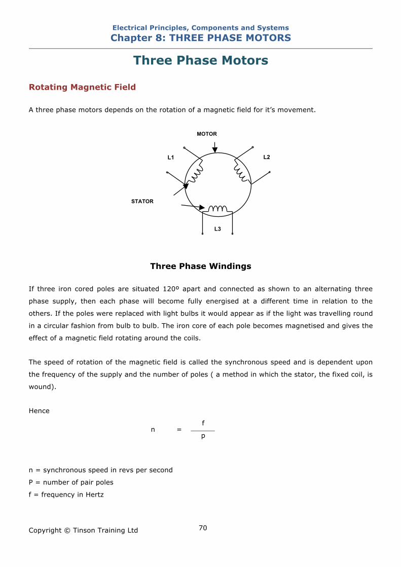
Electrical Principles, Components and Systems Chapter 8: THREE PHASE MOTORS
Copyright © Tinson Training Ltd
70
Three Phase Motors Rotating Magnetic Field A three phase motors depends on the rotation of a magnetic field for it’s movement.
Three Phase Windings
If three iron cored poles are situated 120º apart and connected as shown to an alternating three
phase supply, then each phase will become fully energised at a different time in relation to the
others. If the poles were replaced with light bulbs it would appear as if the light was travelling round
in a circular fashion from bulb to bulb. The iron core of each pole becomes magnetised and gives the
effect of a magnetic field rotating around the coils.
The speed of rotation of the magnetic field is called the synchronous speed and is dependent upon
the frequency of the supply and the number of poles ( a method in which the stator, the fixed coil, is
wound).
Hence
f n =
p
n = synchronous speed in revs per second
P = number of pair poles
f = frequency in Hertz
L1
L3
MOTOR
STATOR
L2
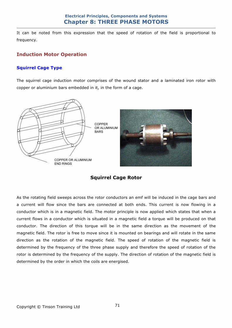
Electrical Principles, Components and Systems Chapter 8: THREE PHASE MOTORS
Copyright © Tinson Training Ltd
71
It can be noted from this expression that the speed of rotation of the field is proportional to
frequency.
Induction Motor Operation Squirrel Cage Type The squirrel cage induction motor comprises of the wound stator and a laminated iron rotor with
copper or aluminium bars embedded in it, in the form of a cage.
Squirrel Cage Rotor As the rotating field sweeps across the rotor conductors an emf will be induced in the cage bars and
a current will flow since the bars are connected at both ends. This current is now flowing in a
conductor which is in a magnetic field. The motor principle is now applied which states that when a
current flows in a conductor which is situated in a magnetic field a torque will be produced on that
conductor. The direction of this torque will be in the same direction as the movement of the
magnetic field. The rotor is free to move since it is mounted on bearings and will rotate in the same
direction as the rotation of the magnetic field. The speed of rotation of the magnetic field is
determined by the frequency of the three phase supply and therefore the speed of rotation of the
rotor is determined by the frequency of the supply. The direction of rotation of the magnetic field is
determined by the order in which the coils are energised.
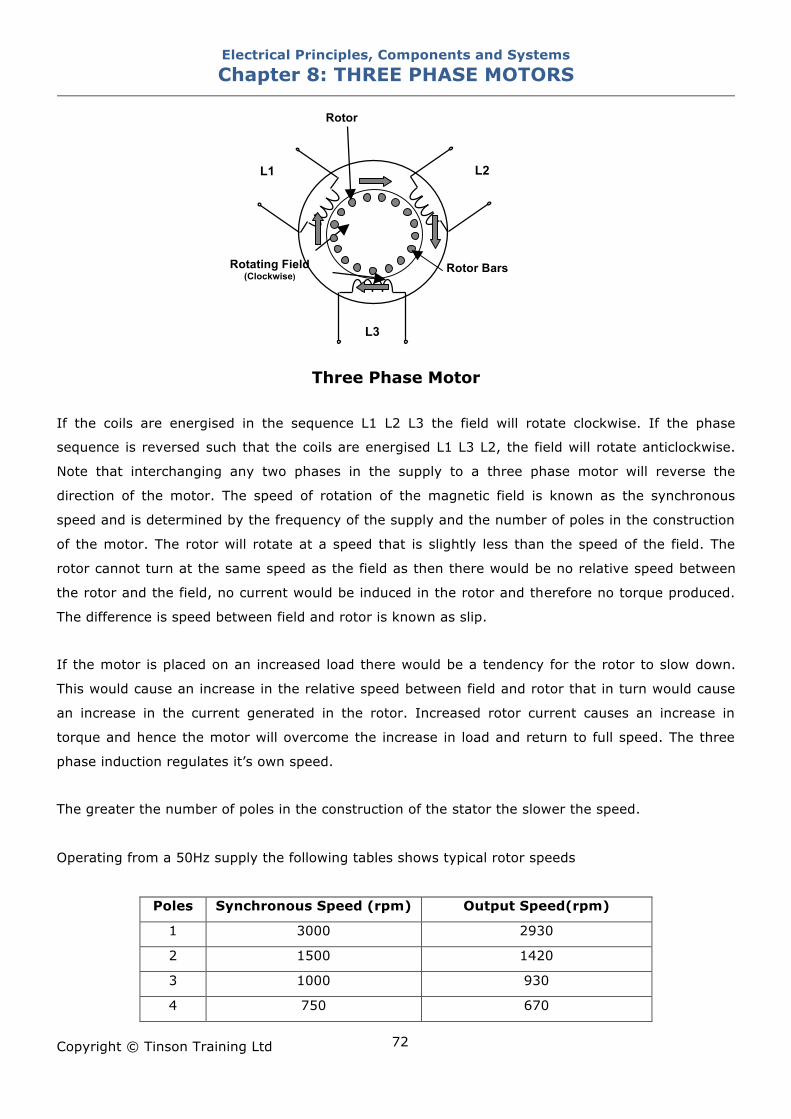
Electrical Principles, Components and Systems Chapter 8: THREE PHASE MOTORS
Copyright © Tinson Training Ltd
72
Three Phase Motor
If the coils are energised in the sequence L1 L2 L3 the field will rotate clockwise. If the phase
sequence is reversed such that the coils are energised L1 L3 L2, the field will rotate anticlockwise.
Note that interchanging any two phases in the supply to a three phase motor will reverse the
direction of the motor. The speed of rotation of the magnetic field is known as the synchronous
speed and is determined by the frequency of the supply and the number of poles in the construction
of the motor. The rotor will rotate at a speed that is slightly less than the speed of the field. The
rotor cannot turn at the same speed as the field as then there would be no relative speed between
the rotor and the field, no current would be induced in the rotor and therefore no torque produced.
The difference is speed between field and rotor is known as slip.
If the motor is placed on an increased load there would be a tendency for the rotor to slow down.
This would cause an increase in the relative speed between field and rotor that in turn would cause
an increase in the current generated in the rotor. Increased rotor current causes an increase in
torque and hence the motor will overcome the increase in load and return to full speed. The three
phase induction regulates it’s own speed.
The greater the number of poles in the construction of the stator the slower the speed.
Operating from a 50Hz supply the following tables shows typical rotor speeds
Poles Synchronous Speed (rpm) Output Speed(rpm)
1 3000 2930
2 1500 1420
3 1000 930
4 750 670
Rotating Field (Clockwise)
L1
L3
Rotor
L2
Rotor Bars
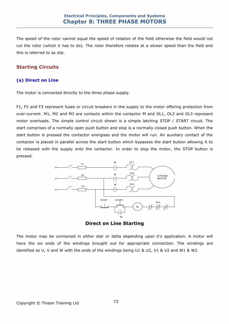
Electrical Principles, Components and Systems Chapter 8: THREE PHASE MOTORS
Copyright © Tinson Training Ltd
73
The speed of the rotor cannot equal the speed of rotation of the field otherwise the field would not
cut the rotor (which it has to do). The rotor therefore rotates at a slower speed than the field and
this is referred to as slip.
Starting Circuits (a) Direct on Line The motor is connected directly to the three phase supply.
F1, F2 and F3 represent fuses or circuit breakers in the supply to the motor offering protection from
over-current. M1, M2 and M3 are contacts within the contactor M and OL1, OL2 and OL3 represent
motor overloads. The simple control circuit shown is a simple latching STOP / START circuit. The
start comprises of a normally open push button and stop is a normally closed push button. When the
start button is pressed the contactor energises and the motor will run. An auxiliary contact of the
contactor is placed in parallel across the start button which bypasses the start button allowing it to
be released with the supply onto the contactor. In order to stop the motor, the STOP button is
pressed.
Direct on Line Starting
The motor may be connected in either star or delta depending upon it’s application. A motor will
have the six ends of the windings brought out for appropriate connection. The windings are
identified as U, V and W with the ends of the windings being U1 & U2, V1 & V2 and W1 & W2
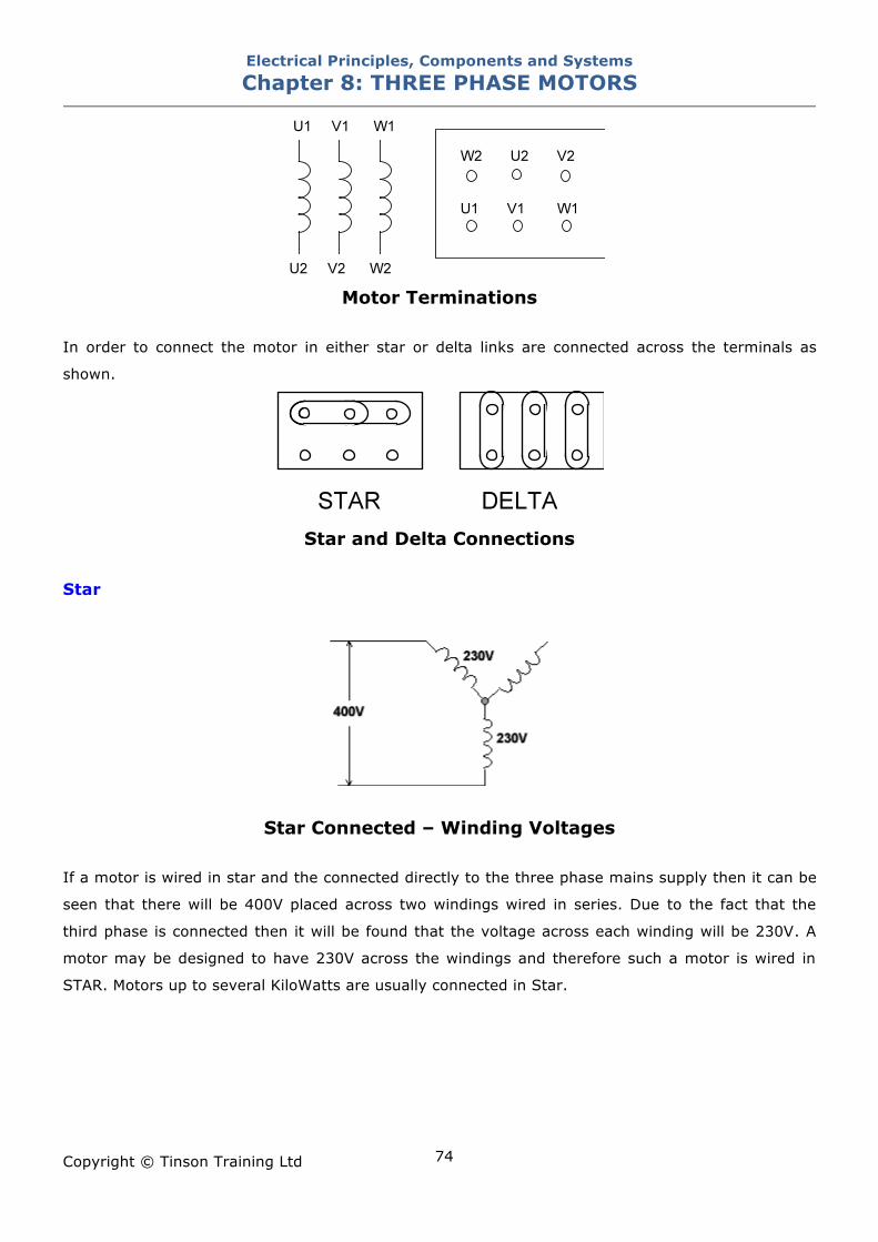
Electrical Principles, Components and Systems Chapter 8: THREE PHASE MOTORS
Copyright © Tinson Training Ltd
74
Motor Terminations
In order to connect the motor in either star or delta links are connected across the terminals as
shown.
Star and Delta Connections
Star
Star Connected – Winding Voltages If a motor is wired in star and the connected directly to the three phase mains supply then it can be
seen that there will be 400V placed across two windings wired in series. Due to the fact that the
third phase is connected then it will be found that the voltage across each winding will be 230V. A
motor may be designed to have 230V across the windings and therefore such a motor is wired in
STAR. Motors up to several KiloWatts are usually connected in Star.
Electrical Principles, Components and Systems Chapter 8: THREE PHASE MOTORS
Copyright © Tinson Training Ltd
75
Delta
Delta Connected – Winding Voltages
If a motor is connected in Delta across a 400V supply it can be seen that the voltage across each
winding will be 400V. A motor wired in Delta will have windings that are intended to have 400V
across them to deliver maximum power. Large power motors of more than several KWatts are
usually connected in Delta
Delta Connected – Winding Voltages
If a motor is wired in delta and connected to a three phase system with a line voltage of 230V then
the voltage across each winding will be 230V. Such a three phase output would be provided by a
single phase inverter
(b)Star - Delta Starter Induction motors can take excessive starting currents especially when connected in delta which can
be up to seven times the normal running currents. These high currents often cannot be tolerated
and therefore it is necessary to provide some method of restricting the start current. A star
connection has two windings connected across the phases and will draw less current than a delta
connection and therefore can be used to limit the start current. After a period of time the connection
is switched over to a delta arrangement.
400V 400V
400V
400V
Electrical Principles, Components and Systems Chapter 8: THREE PHASE MOTORS
Copyright © Tinson Training Ltd
76
Star – Delta Starter
The motor is first switched into star by energising KM1 and at the same time the timing relay K1T is
also energised. This timing relay has a variable delay which when it operates causes KM1 to be de-
energised, removing the star connection and energising KM2 which creates the delta connection.
KM3 remains energised throughout.
(c) Inverters and Soft Start Units
A more common method of starting large motors is by using an Inverter or Soft Start Unit. Both of
these will electronically limit the increase of current at start up. The motor will be driven gently up
to full speed at a rate that is appropriate for the application and can be set within the inverter of soft
start.
Motor Testing There are three main electrical tests that can be carried out on a three phase induction motor
1. Connections Ensure that the connections to the motor are secure. Loose connections can cause local heating and
poor performance of the motor.
2. Continuity of windings. All three windings should have an equal resistance. The actual value of resistance for any motor may
be difficult to predetermine. The power rating of the motor will determine the resistance. The larger
the motor, in terms of power rating, the lesser the resistance of the windings. With lesser resistance
Electrical Principles, Components and Systems Chapter 8: THREE PHASE MOTORS
Copyright © Tinson Training Ltd
77
a greater current will flow in the windings and therefore greater torque is produced. In all three
phase motors the resistance of the winding for the three coils must be equal. Any imbalance will
indicate that one or more windings have suffered damage. The resistance of the windings is checked
by using a multimeter, set on resistance, across the two ends of the individual coils eg. U1 to U2, V1
to V2 and W1 to W2.
Checking motor winding resistance 3. Insulation Tests
To test the insulation of the windings there are two tests that can be carried out.
(a) Insulation between any winding and the case of the motor
U1 to case
V1 to case
W1 to case
(b) Insulation between two pairs of windings
U1 to V1 ( or U2 to V2 )
U1 to W1 ( or U2 to W2 )
V1 to W1 ( or V2 to W2 )
Electrical Principles, Components and Systems Chapter 8: THREE PHASE MOTORS
Copyright © Tinson Training Ltd
78
ON LINE EXERCISE
Click here to access Chapter 8: Three Phase Motors - On Line Exercises
Electrical Principles, Components and Systems Chapter 9: SINGLE PHASE MOTORS
Copyright © Tinson Training Ltd
79
Chapter 9
Single Phase Induction
Motors
At the end of this section you will have an understanding of • the principle of operation of a Single Phase AC Motor • the construction and operation of capacitor start motors
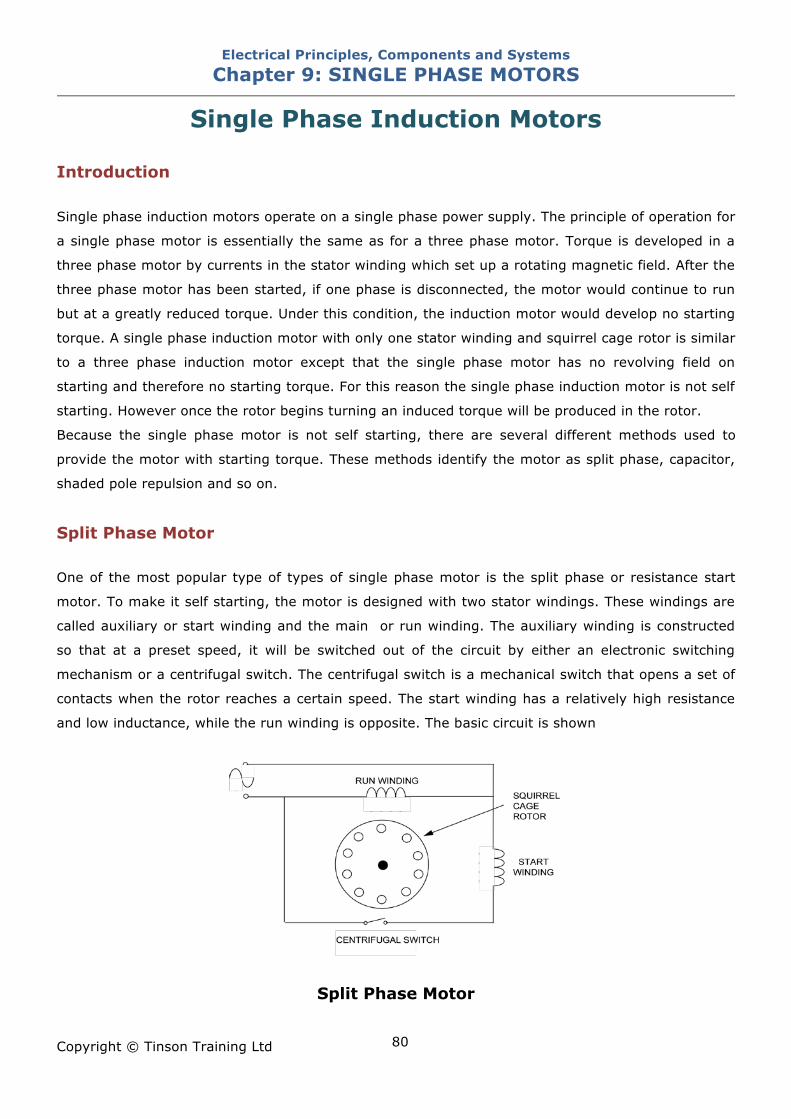
Electrical Principles, Components and Systems Chapter 9: SINGLE PHASE MOTORS
Copyright © Tinson Training Ltd
80
Single Phase Induction Motors
Introduction Single phase induction motors operate on a single phase power supply. The principle of operation for
a single phase motor is essentially the same as for a three phase motor. Torque is developed in a
three phase motor by currents in the stator winding which set up a rotating magnetic field. After the
three phase motor has been started, if one phase is disconnected, the motor would continue to run
but at a greatly reduced torque. Under this condition, the induction motor would develop no starting
torque. A single phase induction motor with only one stator winding and squirrel cage rotor is similar
to a three phase induction motor except that the single phase motor has no revolving field on
starting and therefore no starting torque. For this reason the single phase induction motor is not self
starting. However once the rotor begins turning an induced torque will be produced in the rotor.
Because the single phase motor is not self starting, there are several different methods used to
provide the motor with starting torque. These methods identify the motor as split phase, capacitor,
shaded pole repulsion and so on.
Split Phase Motor One of the most popular type of types of single phase motor is the split phase or resistance start
motor. To make it self starting, the motor is designed with two stator windings. These windings are
called auxiliary or start winding and the main or run winding. The auxiliary winding is constructed
so that at a preset speed, it will be switched out of the circuit by either an electronic switching
mechanism or a centrifugal switch. The centrifugal switch is a mechanical switch that opens a set of
contacts when the rotor reaches a certain speed. The start winding has a relatively high resistance
and low inductance, while the run winding is opposite. The basic circuit is shown
Split Phase Motor
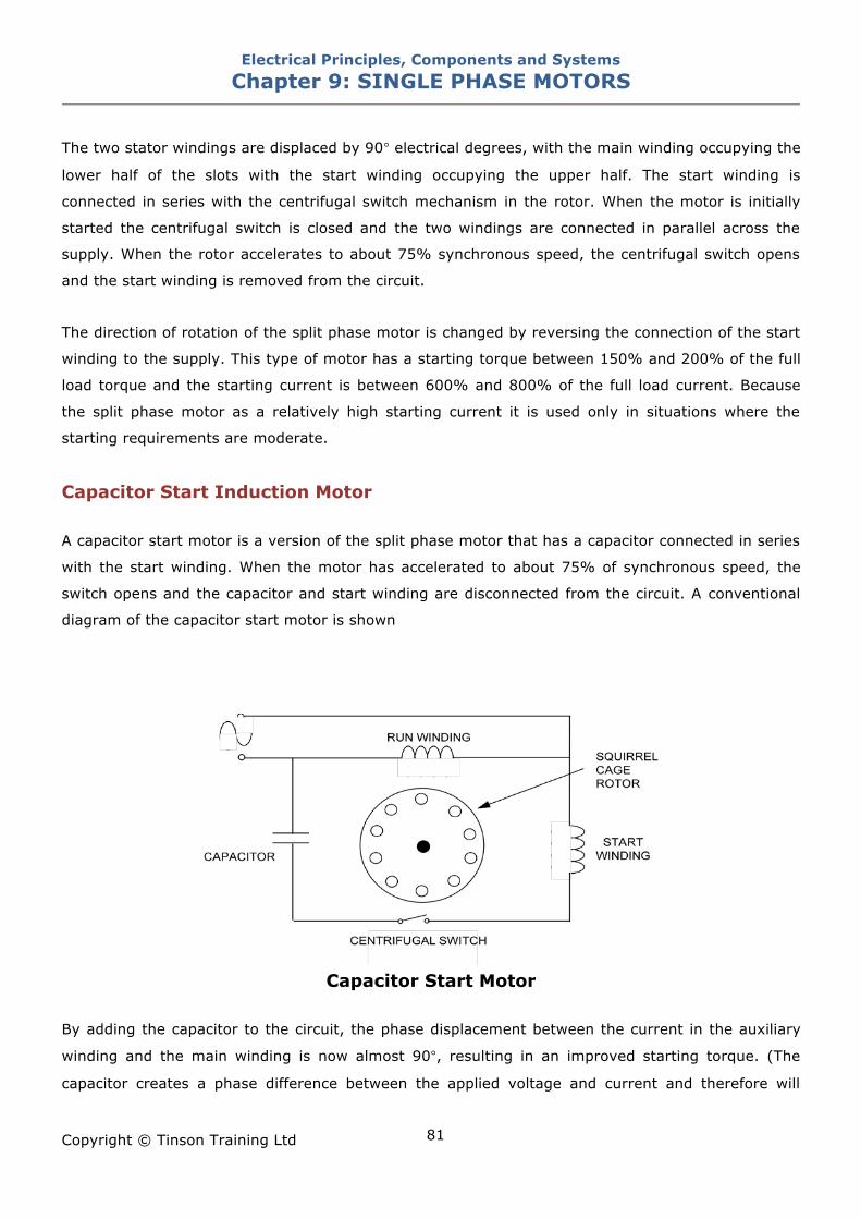
Electrical Principles, Components and Systems Chapter 9: SINGLE PHASE MOTORS
Copyright © Tinson Training Ltd
81
The two stator windings are displaced by 90° electrical degrees, with the main winding occupying the
lower half of the slots with the start winding occupying the upper half. The start winding is
connected in series with the centrifugal switch mechanism in the rotor. When the motor is initially
started the centrifugal switch is closed and the two windings are connected in parallel across the
supply. When the rotor accelerates to about 75% synchronous speed, the centrifugal switch opens
and the start winding is removed from the circuit.
The direction of rotation of the split phase motor is changed by reversing the connection of the start
winding to the supply. This type of motor has a starting torque between 150% and 200% of the full
load torque and the starting current is between 600% and 800% of the full load current. Because
the split phase motor as a relatively high starting current it is used only in situations where the
starting requirements are moderate.
Capacitor Start Induction Motor A capacitor start motor is a version of the split phase motor that has a capacitor connected in series
with the start winding. When the motor has accelerated to about 75% of synchronous speed, the
switch opens and the capacitor and start winding are disconnected from the circuit. A conventional
diagram of the capacitor start motor is shown
Capacitor Start Motor
By adding the capacitor to the circuit, the phase displacement between the current in the auxiliary
winding and the main winding is now almost 90°, resulting in an improved starting torque. (The
capacitor creates a phase difference between the applied voltage and current and therefore will
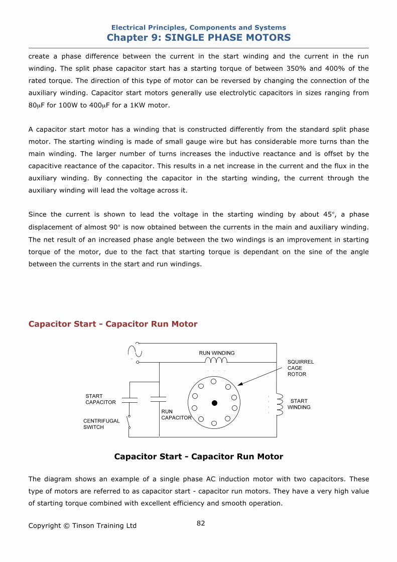
Electrical Principles, Components and Systems Chapter 9: SINGLE PHASE MOTORS
Copyright © Tinson Training Ltd
82
create a phase difference between the current in the start winding and the current in the run
winding. The split phase capacitor start has a starting torque of between 350% and 400% of the
rated torque. The direction of this type of motor can be reversed by changing the connection of the
auxiliary winding. Capacitor start motors generally use electrolytic capacitors in sizes ranging from
80µF for 100W to 400µF for a 1KW motor.
A capacitor start motor has a winding that is constructed differently from the standard split phase
motor. The starting winding is made of small gauge wire but has considerable more turns than the
main winding. The larger number of turns increases the inductive reactance and is offset by the
capacitive reactance of the capacitor. This results in a net increase in the current and the flux in the
auxiliary winding. By connecting the capacitor in the starting winding, the current through the
auxiliary winding will lead the voltage across it.
Since the current is shown to lead the voltage in the starting winding by about 45°, a phase
displacement of almost 90° is now obtained between the currents in the main and auxiliary winding.
The net result of an increased phase angle between the two windings is an improvement in starting
torque of the motor, due to the fact that starting torque is dependant on the sine of the angle
between the currents in the start and run windings.
Capacitor Start - Capacitor Run Motor
Capacitor Start - Capacitor Run Motor
The diagram shows an example of a single phase AC induction motor with two capacitors. These
type of motors are referred to as capacitor start - capacitor run motors. They have a very high value
of starting torque combined with excellent efficiency and smooth operation.
Electrical Principles, Components and Systems Chapter 9: SINGLE PHASE MOTORS
Copyright © Tinson Training Ltd
83
Solid State Switching The centrifugal switch can be replaced by a solid state switching device such as a triac. The
switching of the triac will be controlled from the current in the main winding. When the initial current
is high during starting the triac will be triggered but as the motor accelerates the current in the main
winding decreases until the triac turns off.
Electrical Principles, Components and Systems Chapter 9: SINGLE PHASE MOTORS
Copyright © Tinson Training Ltd
84
ON LINE EXERCISE
Click here to access Chapter 9: Single Phase Motors - On Line Exercises
Electrical Principles, Components and Systems Chapter 10: DC MOTORS
Copyright © Tinson Training Ltd
85
Chapter 10
DC Motors At the end of this section you will have an understanding of • the principle of operation of a DC Motor • the construction and operation of series motors • the construction and operation of shunt motors
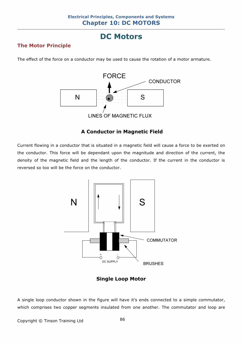
Electrical Principles, Components and Systems Chapter 10: DC MOTORS
Copyright © Tinson Training Ltd
86
DC Motors The Motor Principle The effect of the force on a conductor may be used to cause the rotation of a motor armature.
A Conductor in Magnetic Field
Current flowing in a conductor that is situated in a magnetic field will cause a force to be exerted on
the conductor. This force will be dependant upon the magnitude and direction of the current, the
density of the magnetic field and the length of the conductor. If the current in the conductor is
reversed so too will be the force on the conductor.
Single Loop Motor
A single loop conductor shown in the figure will have it’s ends connected to a simple commutator,
which comprises two copper segments insulated from one another. The commutator and loop are
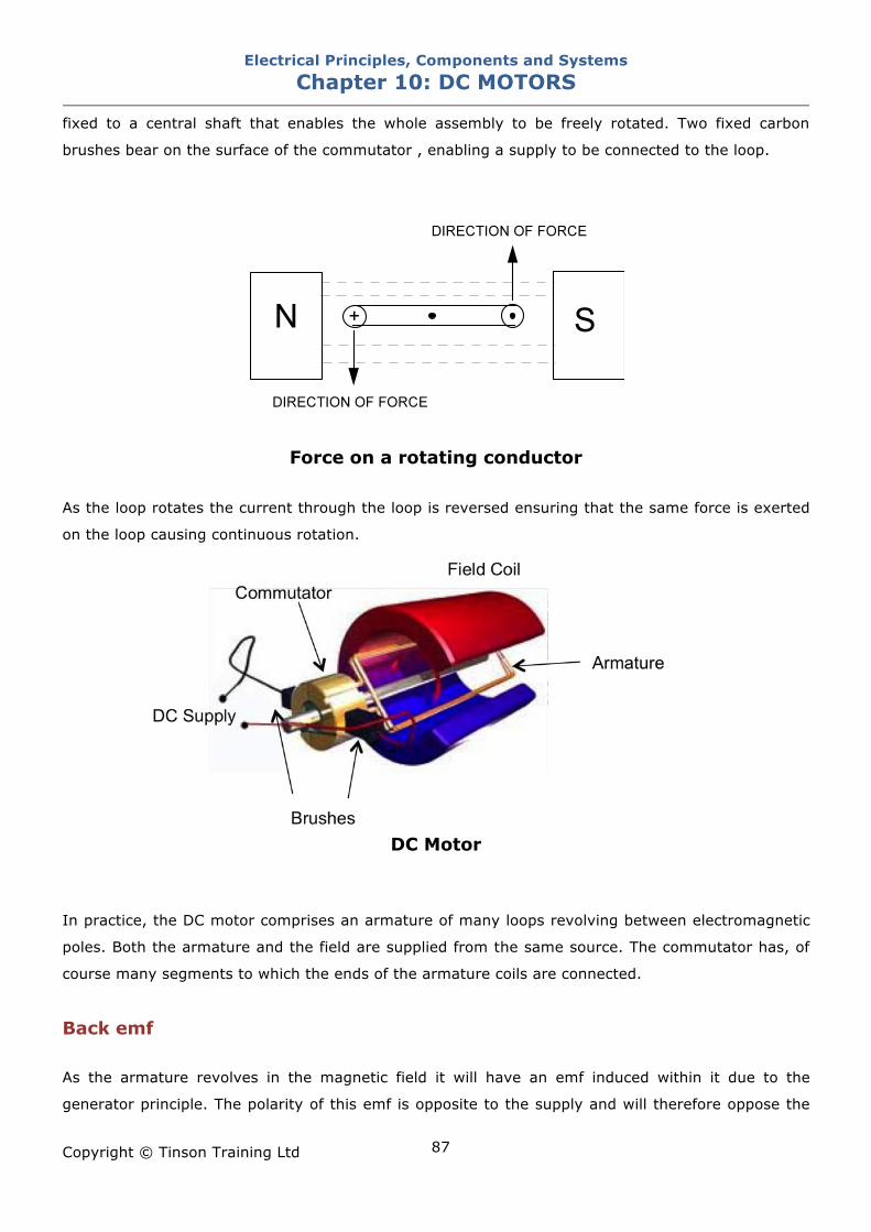
Electrical Principles, Components and Systems Chapter 10: DC MOTORS
Copyright © Tinson Training Ltd
87
fixed to a central shaft that enables the whole assembly to be freely rotated. Two fixed carbon
brushes bear on the surface of the commutator , enabling a supply to be connected to the loop.
Force on a rotating conductor
As the loop rotates the current through the loop is reversed ensuring that the same force is exerted
on the loop causing continuous rotation.
DC Motor
In practice, the DC motor comprises an armature of many loops revolving between electromagnetic
poles. Both the armature and the field are supplied from the same source. The commutator has, of
course many segments to which the ends of the armature coils are connected.
Back emf As the armature revolves in the magnetic field it will have an emf induced within it due to the
generator principle. The polarity of this emf is opposite to the supply and will therefore oppose the
Electrical Principles, Components and Systems Chapter 10: DC MOTORS
Copyright © Tinson Training Ltd
88
supply. This induced emf is called back emf. Clearly this back emf cannot be of the same magnitude
as the supply since if it were it would totally oppose the supply and no current would flow in the
armature. As current must flow in the armature to produce rotation, and as the armature must
have resistance, there must be a volt drop in the armature circuit. This volt drop is the product of
the armature current (Ia) and the armature resistance (Ra).
Armature volt drop = Ia X Ra
It is this voltage that is the difference between the supply voltage and the back emf.
E = V - (Ia X Ra)
Torque Torque = force X radius
Force = B I L
B = density of magnetic field
I = Current
L = length of conductor
Torque = B X Ia X L X radius
Since B L and radius are constant for a machine the torque is proportional to armature current.
Mechanical power output is given by
P = 2 $ n T
where n =speed
T = torque
Power input will be the electrical power input
P = Vs X Ia (Vs is the supply voltage)
Therefore
Vs X Ia = 2 $ n T
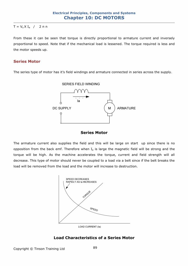
Electrical Principles, Components and Systems Chapter 10: DC MOTORS
Copyright © Tinson Training Ltd
89
T = Vs X Ia / 2 $ n
From these it can be seen that torque is directly proportional to armature current and inversely
proportional to speed. Note that if the mechanical load is lessened. The torque required is less and
the motor speeds up.
Series Motor The series type of motor has it’s field windings and armature connected in series across the supply.
Series Motor
The armature current also supplies the field and this will be large on start up since there is no
opposition from the back emf. Therefore when Ia is large the magnetic field will be strong and the
torque will be high. As the machine accelerates the torque, current and field strength will all
decrease. This type of motor should never be coupled to a load via a belt since if the belt breaks the
load will be removed from the load and the motor will increase to destruction.
Load Characteristics of a Series Motor
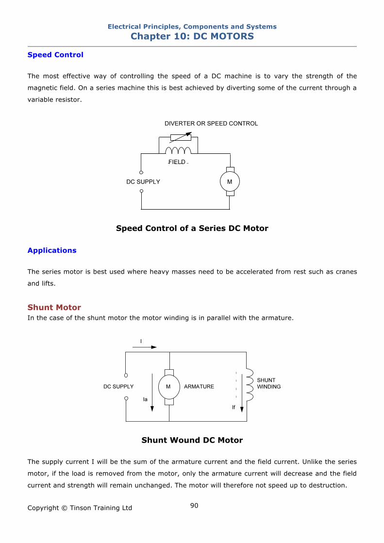
Electrical Principles, Components and Systems Chapter 10: DC MOTORS
Copyright © Tinson Training Ltd
90
Speed Control The most effective way of controlling the speed of a DC machine is to vary the strength of the
magnetic field. On a series machine this is best achieved by diverting some of the current through a
variable resistor.
Speed Control of a Series DC Motor
Applications The series motor is best used where heavy masses need to be accelerated from rest such as cranes
and lifts.
Shunt Motor In the case of the shunt motor the motor winding is in parallel with the armature.
Shunt Wound DC Motor
The supply current I will be the sum of the armature current and the field current. Unlike the series
motor, if the load is removed from the motor, only the armature current will decrease and the field
current and strength will remain unchanged. The motor will therefore not speed up to destruction.
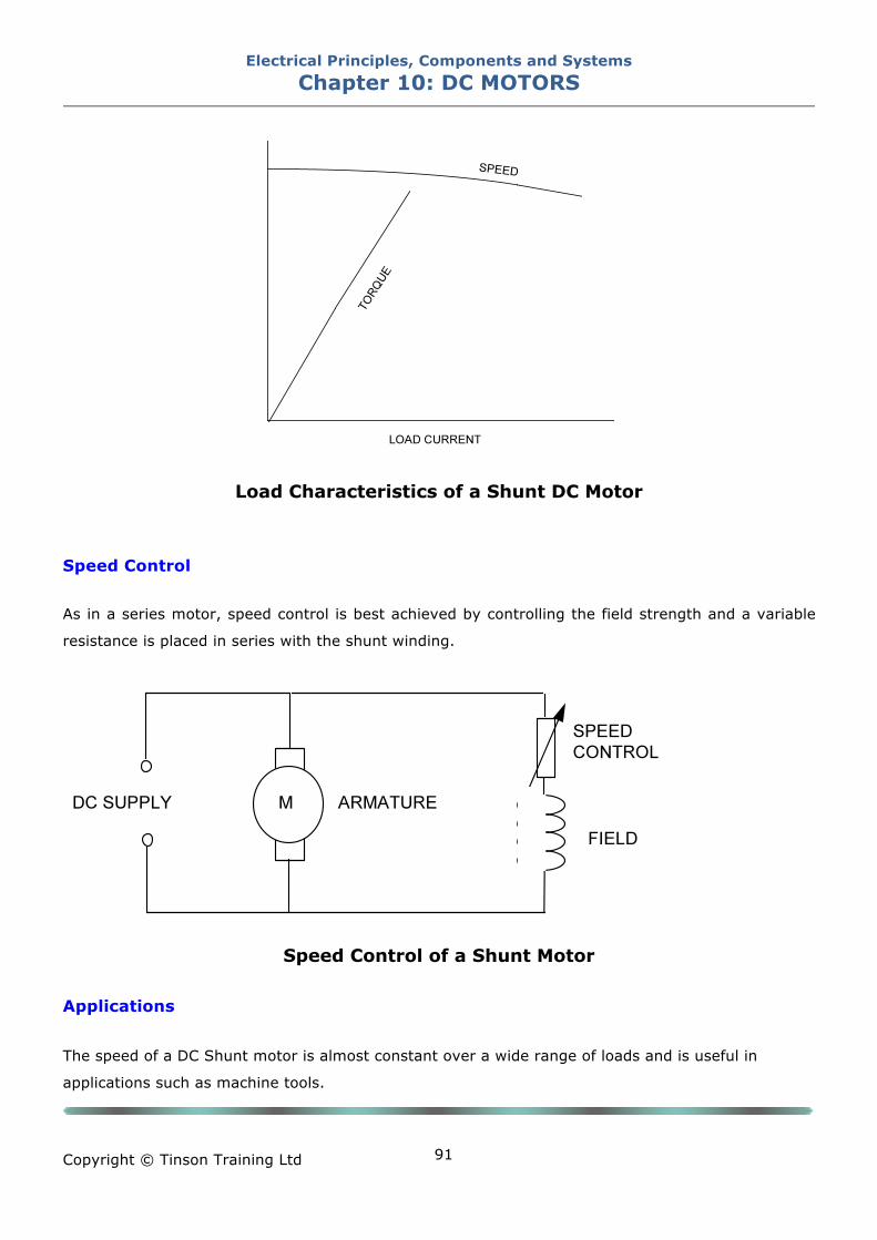
Electrical Principles, Components and Systems Chapter 10: DC MOTORS
Copyright © Tinson Training Ltd
91
Load Characteristics of a Shunt DC Motor
Speed Control As in a series motor, speed control is best achieved by controlling the field strength and a variable
resistance is placed in series with the shunt winding.
Speed Control of a Shunt Motor
Applications
The speed of a DC Shunt motor is almost constant over a wide range of loads and is useful in
applications such as machine tools.

Electrical Principles, Components and Systems Chapter 10: DC MOTORS
Copyright © Tinson Training Ltd
92
ON LINE EXERCISE
Click here to access Chapter 10: DC Motors - On Line Exercises
Electrical Principles, Components and Systems Chapter 11: CONTACTORS AND RELAYS
Copyright © Tinson Training Ltd
93
Chapter 11
Contactors and Relays At the end of this section you will have an understanding of • the function and operation of a relay • the function and operation of a contactor • how to test relays and contactors • how contactors are used in control circuits
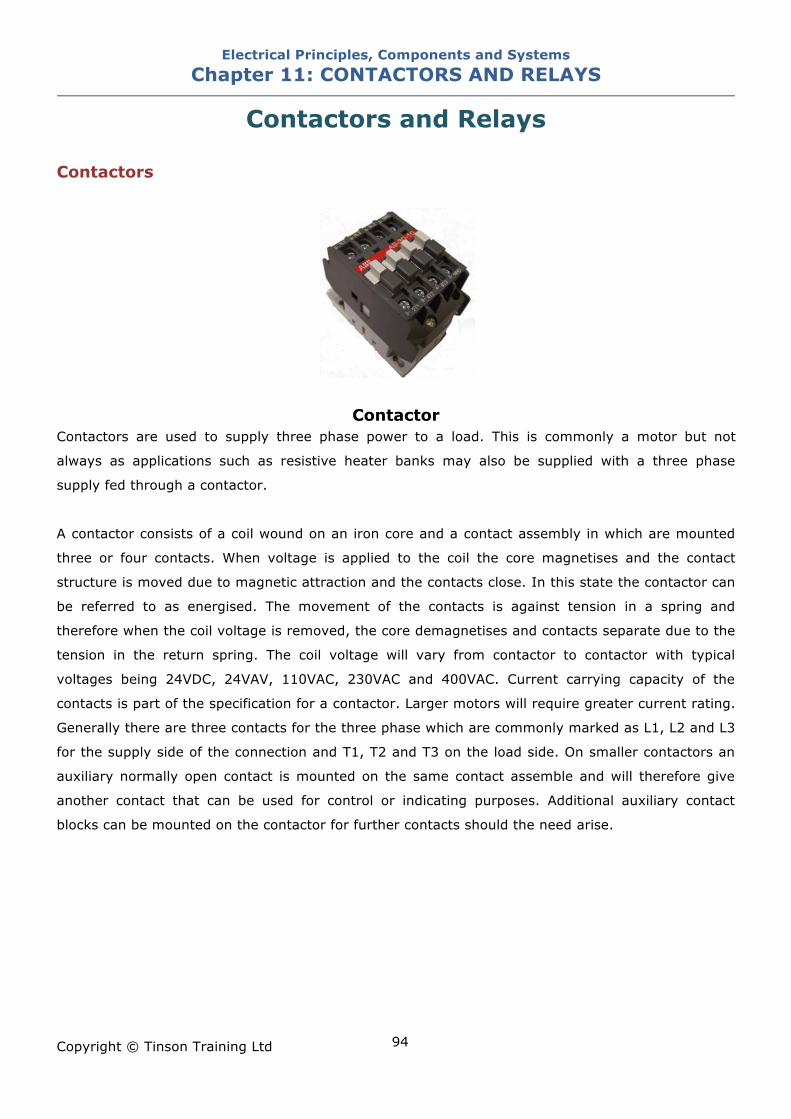
Electrical Principles, Components and Systems Chapter 11: CONTACTORS AND RELAYS
Copyright © Tinson Training Ltd
94
Contactors and Relays Contactors
Contactor Contactors are used to supply three phase power to a load. This is commonly a motor but not
always as applications such as resistive heater banks may also be supplied with a three phase
supply fed through a contactor.
A contactor consists of a coil wound on an iron core and a contact assembly in which are mounted
three or four contacts. When voltage is applied to the coil the core magnetises and the contact
structure is moved due to magnetic attraction and the contacts close. In this state the contactor can
be referred to as energised. The movement of the contacts is against tension in a spring and
therefore when the coil voltage is removed, the core demagnetises and contacts separate due to the
tension in the return spring. The coil voltage will vary from contactor to contactor with typical
voltages being 24VDC, 24VAV, 110VAC, 230VAC and 400VAC. Current carrying capacity of the
contacts is part of the specification for a contactor. Larger motors will require greater current rating.
Generally there are three contacts for the three phase which are commonly marked as L1, L2 and L3
for the supply side of the connection and T1, T2 and T3 on the load side. On smaller contactors an
auxiliary normally open contact is mounted on the same contact assemble and will therefore give
another contact that can be used for control or indicating purposes. Additional auxiliary contact
blocks can be mounted on the contactor for further contacts should the need arise.
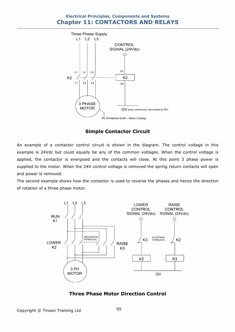
Electrical Principles, Components and Systems Chapter 11: CONTACTORS AND RELAYS
Copyright © Tinson Training Ltd
95
Simple Contactor Circuit
An example of a contactor control circuit is shown in the diagram. The control voltage in this
example is 24Vdc but could equally be any of the common voltages. When the control voltage is
applied, the contactor is energised and the contacts will close. At this point 3 phase power is
supplied to the motor. When the 24V control voltage is removed the spring return contacts will open
and power is removed.
The second example shows how the contactor is used to reverse the phases and hence the direction
of rotation of a three phase motor.
Three Phase Motor Direction Control
Electrical Principles, Components and Systems Chapter 11: CONTACTORS AND RELAYS
Copyright © Tinson Training Ltd
96
Interlocking Electrical interlocking is the technique whereby contacts of a relay or contactor are used to inhibit an
operation of control circuit. In the direction control of the three phase motor interlocking is included
to ensure that the control system does not attempt to send the motor in both directions at the same
time. This is an obvious impossibility but consider what would happen if both the up and down
contactor were to energise at the same time. The result would be that two phases would be shorted
together. This would clearly be unacceptable. Interlocking contacts are included into the circuit to
ensure that this cannot happen. Interlocking may occur between two machines whereby if one
machine stops or a jam occurs it would inhibit the operation of a preceding machine. Safety systems
are interlocks where when a safety guard is moved out of position the machine will not operate.
Ratings All contactors are rated in terms of
• the operating voltage for the coil
It is important that the correct rating used when replacing contactors. Using a contactor that has a
rated voltage less then the control voltage would probably burn out the coil. Using a contactor with a
rated voltage higher than the control voltage will probably cause non operation of the contactor
• the maximum contact current
The contacts of a contactor have a maximum current rating. This current rating like many other
devices should not be exceeded. Exceeding this current will cause the contacts to overheat.
Testing There is only one real test for a contactor in isolation and that is to test the continuity of the coil by
using a multi-meter to check across the connections of the coil. These are marked A1 and A2. It is
probably not possible to determine the reading that should be obtained. It is the best test that
continuity is obtained. Open circuit reading would indicate that the coil has burnt out.
A contactor can be tested for it’s operation by connecting the coil to the required voltage and
checking that the coil energises. This is an acceptable test when the control voltage is low i.e. 24V
but extreme caution should be exercised when connecting to a higher voltage.
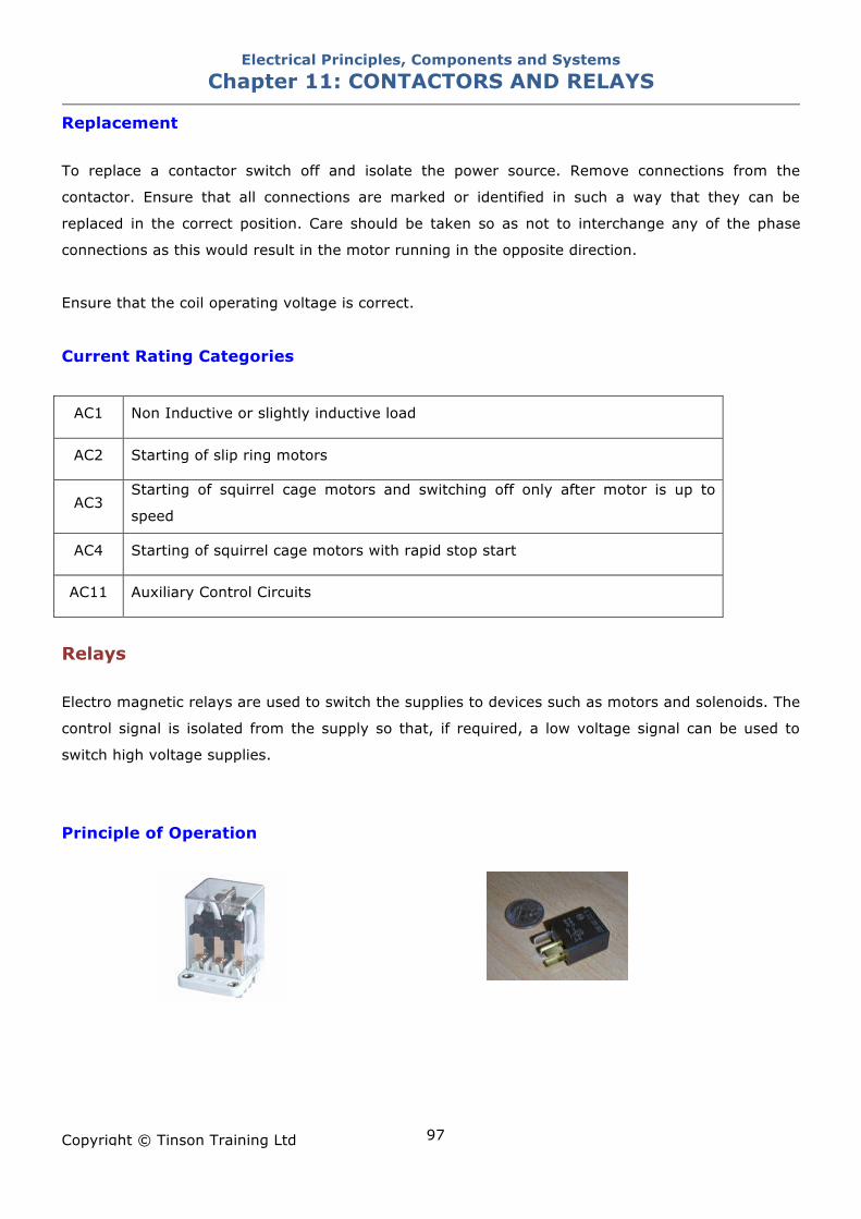
Electrical Principles, Components and Systems Chapter 11: CONTACTORS AND RELAYS
Copyright © Tinson Training Ltd
97
Replacement To replace a contactor switch off and isolate the power source. Remove connections from the
contactor. Ensure that all connections are marked or identified in such a way that they can be
replaced in the correct position. Care should be taken so as not to interchange any of the phase
connections as this would result in the motor running in the opposite direction.
Ensure that the coil operating voltage is correct.
Current Rating Categories
AC1 Non Inductive or slightly inductive load
AC2 Starting of slip ring motors
AC3 Starting of squirrel cage motors and switching off only after motor is up to
speed
AC4 Starting of squirrel cage motors with rapid stop start
AC11 Auxiliary Control Circuits
Relays
Electro magnetic relays are used to switch the supplies to devices such as motors and solenoids. The
control signal is isolated from the supply so that, if required, a low voltage signal can be used to
switch high voltage supplies.
Principle of Operation
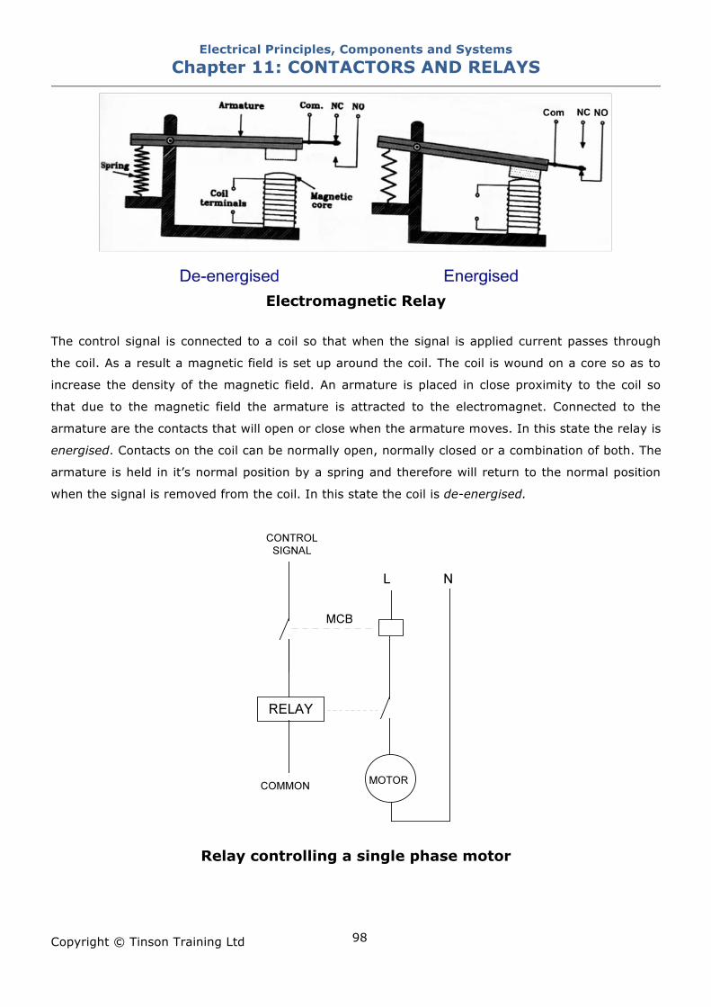
Electrical Principles, Components and Systems Chapter 11: CONTACTORS AND RELAYS
Copyright © Tinson Training Ltd
98
Electromagnetic Relay
The control signal is connected to a coil so that when the signal is applied current passes through
the coil. As a result a magnetic field is set up around the coil. The coil is wound on a core so as to
increase the density of the magnetic field. An armature is placed in close proximity to the coil so
that due to the magnetic field the armature is attracted to the electromagnet. Connected to the
armature are the contacts that will open or close when the armature moves. In this state the relay is
energised. Contacts on the coil can be normally open, normally closed or a combination of both. The
armature is held in it’s normal position by a spring and therefore will return to the normal position
when the signal is removed from the coil. In this state the coil is de-energised.
Relay controlling a single phase motor
Electrical Principles, Components and Systems Chapter 11: CONTACTORS AND RELAYS
Copyright © Tinson Training Ltd
99
The figure shows a relay being used to control a single phase motor. The control signal, generated
from a control system, which could be either DC or AC, energises the relay and switches the AC
supply onto the motor. Relays are typically used on motors that carry fairly low currents. The
important characteristics of a relay are
The combination of contacts – how many, normally open, normally closed
The operating voltage of the coil
The current rating of the contacts
Timing Relays Timing functions may often be required within a control circuit. It may be that after an operation is
complete, there needs to be a delay before another operation takes place.
Example: Suppose a mechanism for gripping an object works by inflating an air bag to grip the
container. A sensor may indicate that the gripper has moved into position and the sensor is used to
open a valve to inflate the gripper. The next operation in the sequence would be to raise the gripper
mechanism to lift the object. It would not be sensible to commence the lift operation at the same
time as the inflation since the bag would need time to inflate. There would need to be a time delay
in-between. The control system may be capable of generating this delay (especially if it comes from
a PLC) but in a simple control system that does not use electronics then this may not be possible.
Timing relays can be used to provide this timing operation.
Timing relays are generally available in two types
• Delay on energise
Delay on energise will produce a delay from the time that the coil is energised, which will be upon
receipt of the control signal, to the relay energising. The relay will de-energise immediately once the
control signal is removed.
• Delay on de-energise
Delay on de-energise relays will energise immediately the control signal is applied but will produce a
delay when the control signal is removed. The relay will stay energised for the time delay period and
then de-energise upon expiry of the delay.
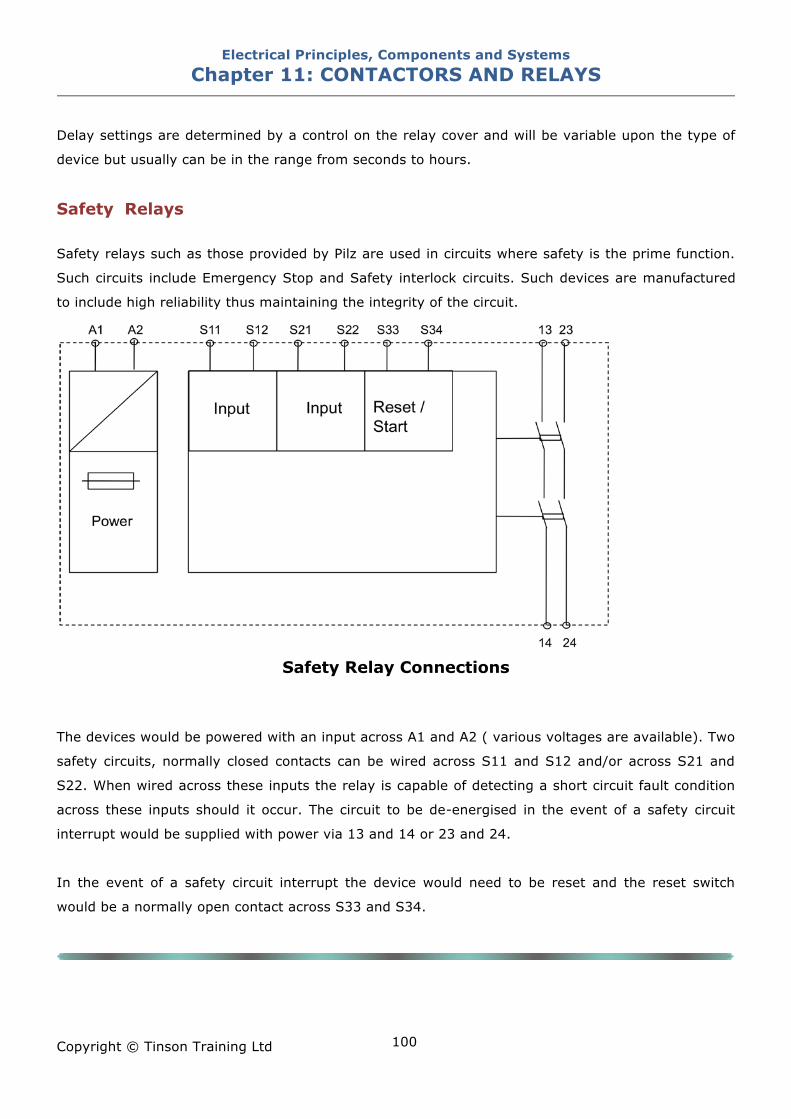
Electrical Principles, Components and Systems Chapter 11: CONTACTORS AND RELAYS
Copyright © Tinson Training Ltd
100
Delay settings are determined by a control on the relay cover and will be variable upon the type of
device but usually can be in the range from seconds to hours.
Safety Relays Safety relays such as those provided by Pilz are used in circuits where safety is the prime function.
Such circuits include Emergency Stop and Safety interlock circuits. Such devices are manufactured
to include high reliability thus maintaining the integrity of the circuit.
Safety Relay Connections
The devices would be powered with an input across A1 and A2 ( various voltages are available). Two
safety circuits, normally closed contacts can be wired across S11 and S12 and/or across S21 and
S22. When wired across these inputs the relay is capable of detecting a short circuit fault condition
across these inputs should it occur. The circuit to be de-energised in the event of a safety circuit
interrupt would be supplied with power via 13 and 14 or 23 and 24.
In the event of a safety circuit interrupt the device would need to be reset and the reset switch
would be a normally open contact across S33 and S34.
Electrical Principles, Components and Systems Chapter 11: CONTACTORS AND RELAYS
Copyright © Tinson Training Ltd
101
ON LINE EXERCISE
Click here to access Chapter 11: Contactors and Relays - On Line Exercises
Electrical Principles, Components and Systems Chapter 12: CONTROL SYSTEMS SENSORS AND CIRCUITS
Copyright © Tinson Training Ltd
102
Chapter 12
Control Systems, Sensors
and Circuits At the end of this section you will have an understanding of • the purpose of a control system • the function of analogue sensors • the operation of optical sensors • the operation of inductive sensors • the operation of capacitive sensors • the main parameters of proximity sensors
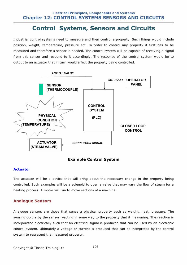
Electrical Principles, Components and Systems Chapter 12: CONTROL SYSTEMS SENSORS AND CIRCUITS
Copyright © Tinson Training Ltd
103
Control Systems, Sensors and Circuits
Industrial control systems need to measure and then control a property. Such things would include
position, weight, temperature, pressure etc. In order to control any property it first has to be
measured and therefore a sensor is needed. The control system will be capable of receiving a signal
from this sensor and respond to it accordingly. The response of the control system would be to
output to an actuator that in turn would affect the property being controlled.
Example Control System Actuator The actuator will be a device that will bring about the necessary change in the property being
controlled. Such examples will be a solenoid to open a valve that may vary the flow of steam for a
heating process. A motor will run to move sections of a machine.
Analogue Sensors
Analogue sensors are those that sense a physical property such as weight, heat, pressure. The
sensing occurs by the sensor reacting in some way to the property that it measuring. The reaction is
incorporated electrically such that an electrical signal is produced that can be used by an electronic
control system. Ultimately a voltage or current is produced that can be interpreted by the control
system to represent the measured property.
PHYSICAL CONDITION
(TEMPERATURE)
SENSOR (THERMOCOUPLE)
ACTUATOR (STEAM VALVE)
CONTROL SYSTEM
(PLC) CLOSED LOOP
CONTROL
OPERATOR PANEL
ACTUAL VALUE SET POINT
CORRECTION SIGNAL
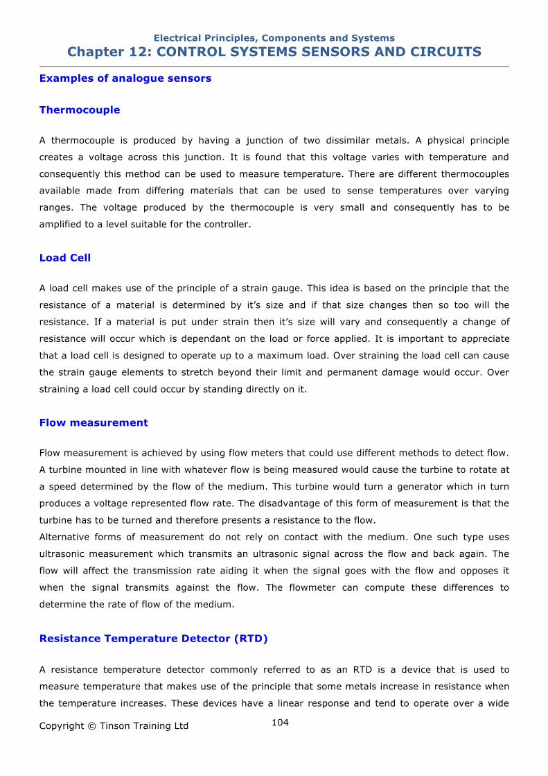
Electrical Principles, Components and Systems Chapter 12: CONTROL SYSTEMS SENSORS AND CIRCUITS
Copyright © Tinson Training Ltd
104
Examples of analogue sensors
Thermocouple A thermocouple is produced by having a junction of two dissimilar metals. A physical principle
creates a voltage across this junction. It is found that this voltage varies with temperature and
consequently this method can be used to measure temperature. There are different thermocouples
available made from differing materials that can be used to sense temperatures over varying
ranges. The voltage produced by the thermocouple is very small and consequently has to be
amplified to a level suitable for the controller.
Load Cell A load cell makes use of the principle of a strain gauge. This idea is based on the principle that the
resistance of a material is determined by it’s size and if that size changes then so too will the
resistance. If a material is put under strain then it’s size will vary and consequently a change of
resistance will occur which is dependant on the load or force applied. It is important to appreciate
that a load cell is designed to operate up to a maximum load. Over straining the load cell can cause
the strain gauge elements to stretch beyond their limit and permanent damage would occur. Over
straining a load cell could occur by standing directly on it.
Flow measurement Flow measurement is achieved by using flow meters that could use different methods to detect flow.
A turbine mounted in line with whatever flow is being measured would cause the turbine to rotate at
a speed determined by the flow of the medium. This turbine would turn a generator which in turn
produces a voltage represented flow rate. The disadvantage of this form of measurement is that the
turbine has to be turned and therefore presents a resistance to the flow.
Alternative forms of measurement do not rely on contact with the medium. One such type uses
ultrasonic measurement which transmits an ultrasonic signal across the flow and back again. The
flow will affect the transmission rate aiding it when the signal goes with the flow and opposes it
when the signal transmits against the flow. The flowmeter can compute these differences to
determine the rate of flow of the medium.
Resistance Temperature Detector (RTD)
A resistance temperature detector commonly referred to as an RTD is a device that is used to
measure temperature that makes use of the principle that some metals increase in resistance when
the temperature increases. These devices have a linear response and tend to operate over a wide
Electrical Principles, Components and Systems Chapter 12: CONTROL SYSTEMS SENSORS AND CIRCUITS
Copyright © Tinson Training Ltd
105
temperature range. They are categorised by their resistance at 0˚C. Typical elements used are
Nickel (Ni), Copper (Cu) but Platinum (Pt) is most commonly used for it’s wide temperature range,
accuracy and stability.
Thermistors Thermistors (thermally sensitive resistors) are similar to RTDs in that they are electrical resistors
whose resistance changes with temperature. Thermistors are manufactured from metal oxide
semiconductor material which is encapsulated in a glass or epoxy bead.
Thermistors have a very high sensitivity, making them extremely responsive to changes in
temperature. For example, a 2252 ! thermistor has a sensitivity of -100 !/°C at room temperature.
In comparison, a 100 ! RTD has a sensitivity of 0.4 !/°C. Thermistors also have a low thermal
mass that results in fast response times, but are limited by a small temperature range.
Thermistors have either a negative temperature coefficient (NTC) or a positive temperature
coefficient (PTC). The first has a resistance which decreases with increasing temperature and the
latter exhibits increased resistance with increasing temperature.
Proximity Sensors
Introduction The sensing of the presence of a material is known as proximity detection. There are several forms
of proximity detectors all of which are industrially important and feature to a considerable extent in
automated equipment. The main use for proximity detectors range from the simple counting of
objects by detecting their presence to checking for faulty assembly and ensuring that objects are
positioned correctly for a subsequent operation.
Microswitches The simplest form of proximity detection is touch detection, using a microswitch, often connected to
a probe, to sense the position of an object. This has significant advantages in that it is not affected
by the type of material, but does have the drawback that it is only confined to objects that have
sufficient mass to operate the mechanism and for objects not to be damaged by being touched.
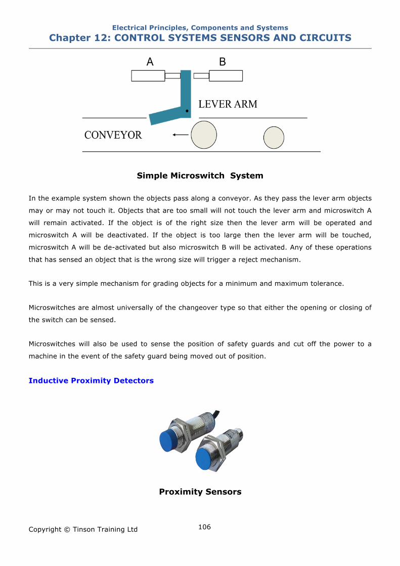
Electrical Principles, Components and Systems Chapter 12: CONTROL SYSTEMS SENSORS AND CIRCUITS
Copyright © Tinson Training Ltd
106
Simple Microswitch System In the example system shown the objects pass along a conveyor. As they pass the lever arm objects
may or may not touch it. Objects that are too small will not touch the lever arm and microswitch A
will remain activated. If the object is of the right size then the lever arm will be operated and
microswitch A will be deactivated. If the object is too large then the lever arm will be touched,
microswitch A will be de-activated but also microswitch B will be activated. Any of these operations
that has sensed an object that is the wrong size will trigger a reject mechanism.
This is a very simple mechanism for grading objects for a minimum and maximum tolerance.
Microswitches are almost universally of the changeover type so that either the opening or closing of
the switch can be sensed.
Microswitches will also be used to sense the position of safety guards and cut off the power to a
machine in the event of the safety guard being moved out of position.
Inductive Proximity Detectors
Proximity Sensors
Electrical Principles, Components and Systems Chapter 12: CONTROL SYSTEMS SENSORS AND CIRCUITS
Copyright © Tinson Training Ltd
107
Inductive proximity detectors consist of a coil which is mounted close to the sensing face of the
device through which an alternating current is passed. This in turn creates a magnetic field in the
area close to the sensing face. If a metal object comes into close proximity with the sensor eddy
currents are created within that object. An eddy current is a current that is created due to
electromagnetic induction. This eddy current circulating within the metal creates a magnetic field
which reacts against the field created by the sensor and is capable of being detected. The change is
usually designed to operate a switched output. The output switch action is predominantly normally
open (NO), although a few types are normally closed (NC).
The overwhelming advantage of the inductive proximity switch is that no part of the switch needs to
touch the object being sensed. Their disadvantage is that they sense metallic objects only and with
a sensitivity that depends upon the type of metal used. The sensitivity is quoted in terms of the
average sensing distance for an object of mild steel. Most inductive proximity sensors are DC
operated , with the choice of current sink or current source. A current source will pass current into a
load; a current sink will accept current to earth from a load. Current ratings are in the region 100-
200mA at DC voltage levels of 5-30V.
Several inductive sensors will have a tell tale LED to indicate that sensing is occurring. This makes
setting up the device easier since the load can and should be disconnected at this time.
Another useful feature of inductive proximity sensors is their repetition rate that is typically in the
order of 200Hz to 2kHz. Inductive sensors are more expensive than microswitches but carry the
advantage of not having to make contact with the object being sensed.
Capacitive Proximity Sensors Capacitive sensing makes use of the stray capacitance that exists between a metal plate and earth.
This quantity can be altered by the presence of a non conducting material as well as earthed or
isolated conducting material. A bridge or resonant circuit detection method can be used, although
the resonant circuit is more common since stray capacitance is usually very small. A noticeable
feature is that the detectable range is much higher than inductive types. Both DC and AC types are
available.
Hall Effect Sensors The Hall effect was discovered in 1879 by Edwin Hall. It was discovered that when a conductor is
placed in a magnetic field and has current passed through it at a right angle to the field, a voltage
will be developed across the other ends of the material.
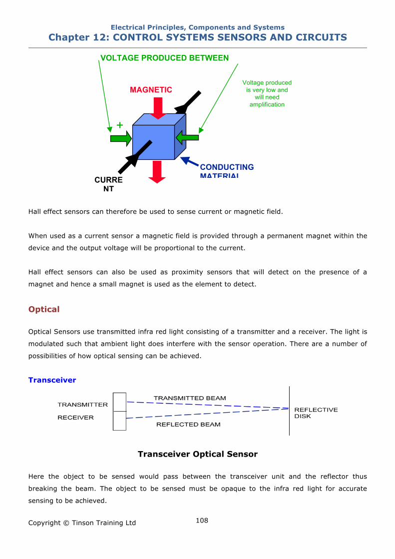
Electrical Principles, Components and Systems Chapter 12: CONTROL SYSTEMS SENSORS AND CIRCUITS
Copyright © Tinson Training Ltd
108
Hall effect sensors can therefore be used to sense current or magnetic field.
When used as a current sensor a magnetic field is provided through a permanent magnet within the
device and the output voltage will be proportional to the current.
Hall effect sensors can also be used as proximity sensors that will detect on the presence of a
magnet and hence a small magnet is used as the element to detect.
Optical Optical Sensors use transmitted infra red light consisting of a transmitter and a receiver. The light is
modulated such that ambient light does interfere with the sensor operation. There are a number of
possibilities of how optical sensing can be achieved.
Transceiver
Transceiver Optical Sensor
Here the object to be sensed would pass between the transceiver unit and the reflector thus
breaking the beam. The object to be sensed must be opaque to the infra red light for accurate
sensing to be achieved.
MAGNETIC
CURRENT
CONDUCTING MATERIAL
VOLTAGE PRODUCED BETWEEN
+
Voltage produced is very low and
will need amplification
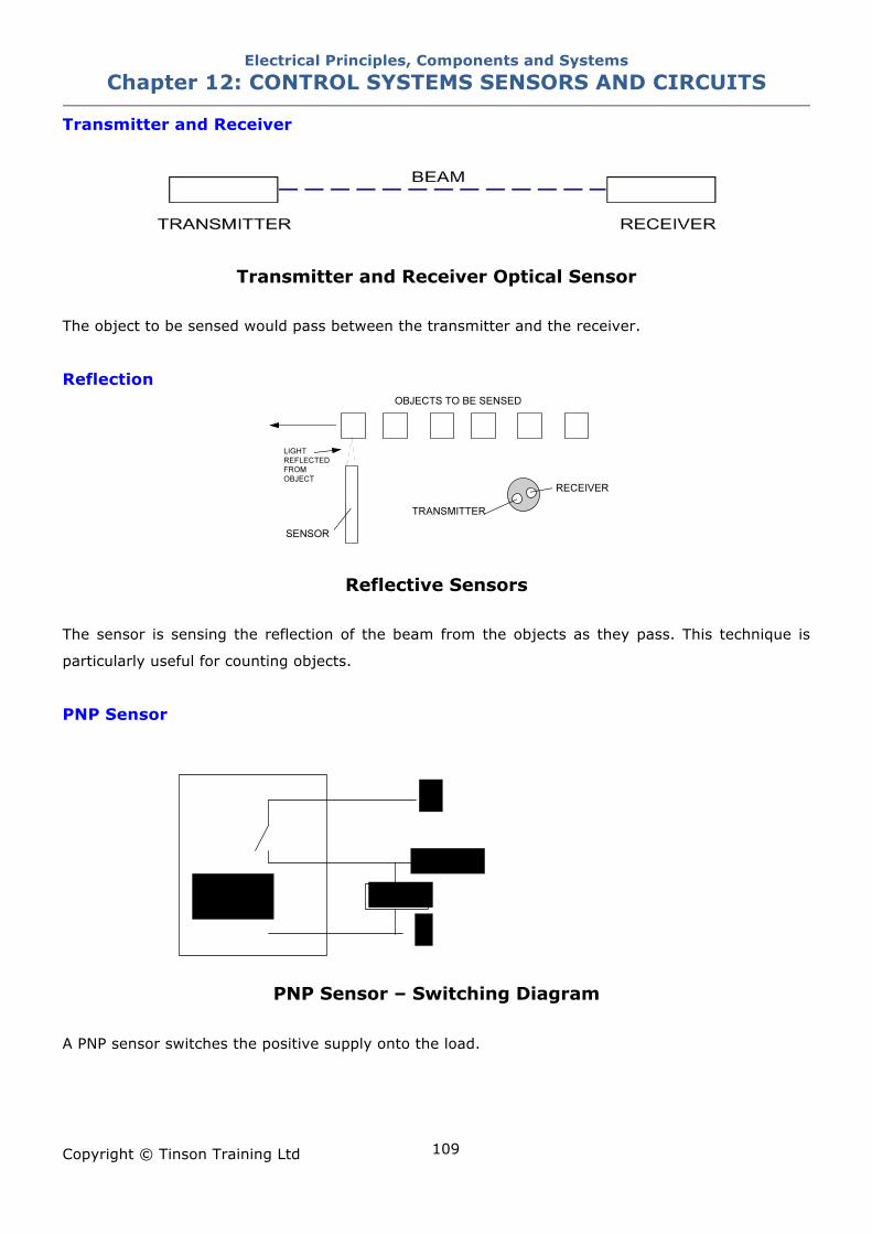
Electrical Principles, Components and Systems Chapter 12: CONTROL SYSTEMS SENSORS AND CIRCUITS
Copyright © Tinson Training Ltd
109
Transmitter and Receiver
Transmitter and Receiver Optical Sensor
The object to be sensed would pass between the transmitter and the receiver.
Reflection
Reflective Sensors
The sensor is sensing the reflection of the beam from the objects as they pass. This technique is
particularly useful for counting objects.
PNP Sensor
PNP Sensor – Switching Diagram
A PNP sensor switches the positive supply onto the load.
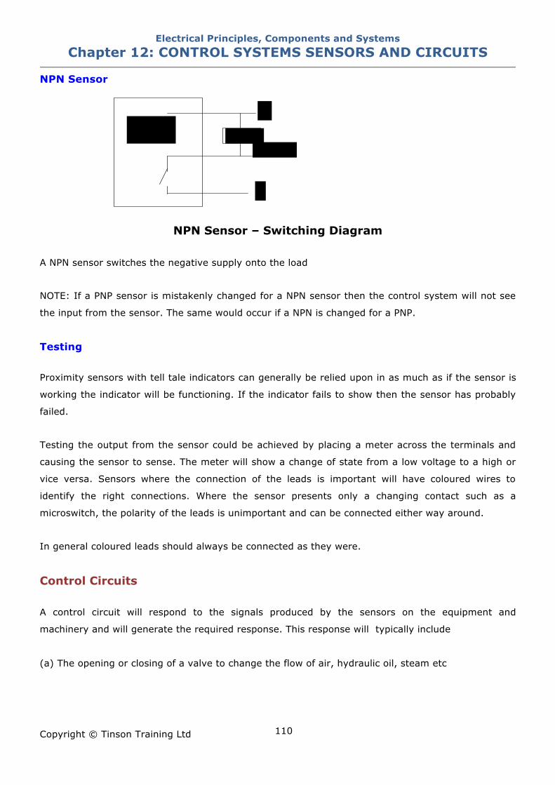
Electrical Principles, Components and Systems Chapter 12: CONTROL SYSTEMS SENSORS AND CIRCUITS
Copyright © Tinson Training Ltd
110
NPN Sensor
NPN Sensor – Switching Diagram
A NPN sensor switches the negative supply onto the load
NOTE: If a PNP sensor is mistakenly changed for a NPN sensor then the control system will not see
the input from the sensor. The same would occur if a NPN is changed for a PNP.
Testing Proximity sensors with tell tale indicators can generally be relied upon in as much as if the sensor is
working the indicator will be functioning. If the indicator fails to show then the sensor has probably
failed.
Testing the output from the sensor could be achieved by placing a meter across the terminals and
causing the sensor to sense. The meter will show a change of state from a low voltage to a high or
vice versa. Sensors where the connection of the leads is important will have coloured wires to
identify the right connections. Where the sensor presents only a changing contact such as a
microswitch, the polarity of the leads is unimportant and can be connected either way around.
In general coloured leads should always be connected as they were.
Control Circuits A control circuit will respond to the signals produced by the sensors on the equipment and
machinery and will generate the required response. This response will typically include
(a) The opening or closing of a valve to change the flow of air, hydraulic oil, steam etc
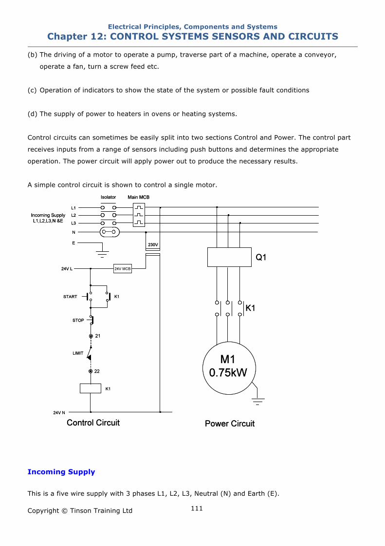
Electrical Principles, Components and Systems Chapter 12: CONTROL SYSTEMS SENSORS AND CIRCUITS
Copyright © Tinson Training Ltd
111
(b) The driving of a motor to operate a pump, traverse part of a machine, operate a conveyor,
operate a fan, turn a screw feed etc.
(c) Operation of indicators to show the state of the system or possible fault conditions
(d) The supply of power to heaters in ovens or heating systems.
Control circuits can sometimes be easily split into two sections Control and Power. The control part
receives inputs from a range of sensors including push buttons and determines the appropriate
operation. The power circuit will apply power out to produce the necessary results.
A simple control circuit is shown to control a single motor.
Incoming Supply
This is a five wire supply with 3 phases L1, L2, L3, Neutral (N) and Earth (E).
Electrical Principles, Components and Systems Chapter 12: CONTROL SYSTEMS SENSORS AND CIRCUITS
Copyright © Tinson Training Ltd
112
Main Isolator
A three pole isolator that physically disconnects all three live phases
Main Circuit Breaker
This will be rated at the appropriate value for all equipment within the system.
Transformer
A 230V / 24V step down transformer is used to create the 24VAC control voltage. Protection in the
form of MCBs may be placed in the primary and secondary circuits.
24V Main Circuit Breaker
This will be rated to ensure that the 24V transformer cannot be overloaded.
Control Circuit
The control circuit shown is a simple Stop / Start Circuit. Contactor K1 is energised when the motor
is required to run and is controlled by the Start and Stop buttons, a limit switch and the auxiliary of
the contactor. When the start push button (PB) is pressed the supply is put onto the coil of the
contactor thus energising it. When K1 energises the auxiliary contact will close across the start PB
which means that the start PB can be released and the contactor will remain energised. This is
referred to as a latching circuit with the auxiliary contact being known as a latching or holding
contact. The motor will now continue to run. The motor is stopped through the control by one of two
possibilities
The STOP PB is pressed
The End Limit Switch is reached. This limit switch is positioned at the physical end of travel that the
motor is allowed to drive to.
Both of these will open and remove the supply from the coil of the contactor which will de-energise
and the motor will stop.
The Limit Switch is on the equipment and is therefore external to the control panel. This is shown by
terminating connectors 21 and 22 and the dotted line to the limit switch. Dotted lines mean that
those items are external to the panel.
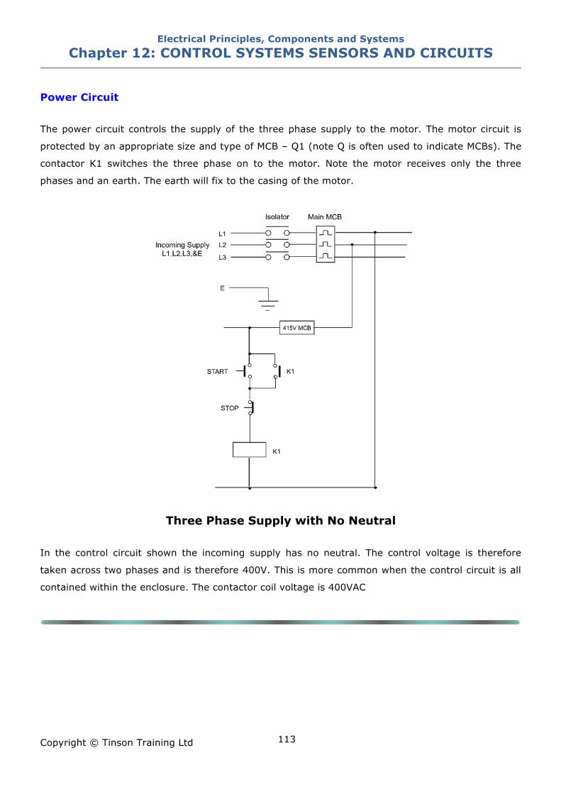
Electrical Principles, Components and Systems Chapter 12: CONTROL SYSTEMS SENSORS AND CIRCUITS
Copyright © Tinson Training Ltd
113
Power Circuit
The power circuit controls the supply of the three phase supply to the motor. The motor circuit is
protected by an appropriate size and type of MCB – Q1 (note Q is often used to indicate MCBs). The
contactor K1 switches the three phase on to the motor. Note the motor receives only the three
phases and an earth. The earth will fix to the casing of the motor.
Three Phase Supply with No Neutral
In the control circuit shown the incoming supply has no neutral. The control voltage is therefore
taken across two phases and is therefore 400V. This is more common when the control circuit is all
contained within the enclosure. The contactor coil voltage is 400VAC
Electrical Principles, Components and Systems Chapter 12: CONTROL SYSTEMS SENSORS AND CIRCUITS
Copyright © Tinson Training Ltd
114
ON LINE EXERCISE
Click here to access Chapter 12 Control Systems - On Line Exercises
Electrical Principles, Components and Systems Chapter 13: PRINCIPLES OF INVERTERS
Copyright © Tinson Training Ltd
115
Chapter 13
Principles of Inverters At the end of this section you will have an understanding of
• motor speed control • principle of operation of an inverter • control signals • parameters
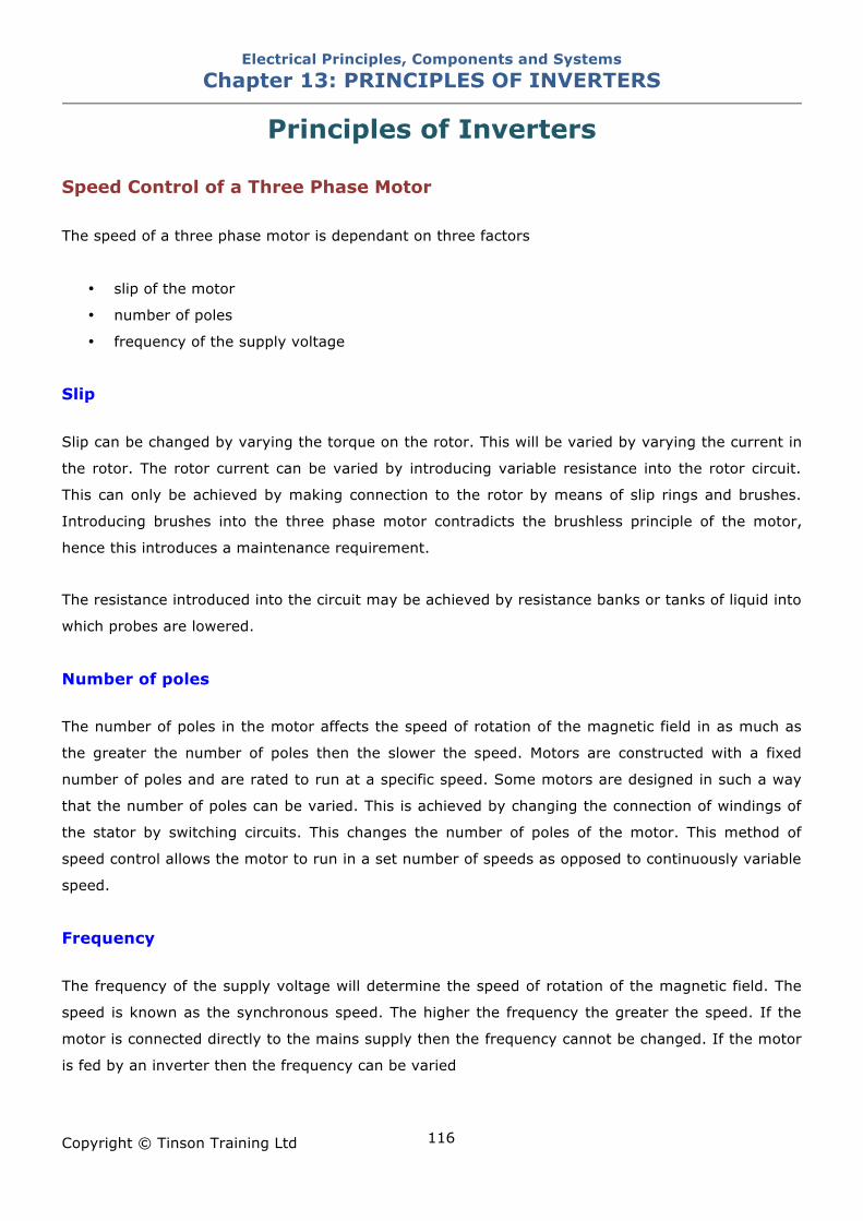
Electrical Principles, Components and Systems Chapter 13: PRINCIPLES OF INVERTERS
Copyright © Tinson Training Ltd
116
Principles of Inverters Speed Control of a Three Phase Motor The speed of a three phase motor is dependant on three factors
• slip of the motor
• number of poles
• frequency of the supply voltage
Slip Slip can be changed by varying the torque on the rotor. This will be varied by varying the current in
the rotor. The rotor current can be varied by introducing variable resistance into the rotor circuit.
This can only be achieved by making connection to the rotor by means of slip rings and brushes.
Introducing brushes into the three phase motor contradicts the brushless principle of the motor,
hence this introduces a maintenance requirement.
The resistance introduced into the circuit may be achieved by resistance banks or tanks of liquid into
which probes are lowered.
Number of poles The number of poles in the motor affects the speed of rotation of the magnetic field in as much as
the greater the number of poles then the slower the speed. Motors are constructed with a fixed
number of poles and are rated to run at a specific speed. Some motors are designed in such a way
that the number of poles can be varied. This is achieved by changing the connection of windings of
the stator by switching circuits. This changes the number of poles of the motor. This method of
speed control allows the motor to run in a set number of speeds as opposed to continuously variable
speed.
Frequency The frequency of the supply voltage will determine the speed of rotation of the magnetic field. The
speed is known as the synchronous speed. The higher the frequency the greater the speed. If the
motor is connected directly to the mains supply then the frequency cannot be changed. If the motor
is fed by an inverter then the frequency can be varied
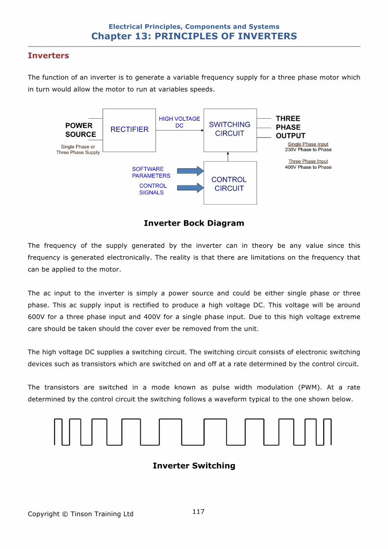
Electrical Principles, Components and Systems Chapter 13: PRINCIPLES OF INVERTERS
Copyright © Tinson Training Ltd
117
Inverters The function of an inverter is to generate a variable frequency supply for a three phase motor which
in turn would allow the motor to run at variables speeds.
Inverter Bock Diagram
The frequency of the supply generated by the inverter can in theory be any value since this
frequency is generated electronically. The reality is that there are limitations on the frequency that
can be applied to the motor.
The ac input to the inverter is simply a power source and could be either single phase or three
phase. This ac supply input is rectified to produce a high voltage DC. This voltage will be around
600V for a three phase input and 400V for a single phase input. Due to this high voltage extreme
care should be taken should the cover ever be removed from the unit.
The high voltage DC supplies a switching circuit. The switching circuit consists of electronic switching
devices such as transistors which are switched on and off at a rate determined by the control circuit.
The transistors are switched in a mode known as pulse width modulation (PWM). At a rate
determined by the control circuit the switching follows a waveform typical to the one shown below.
Inverter Switching
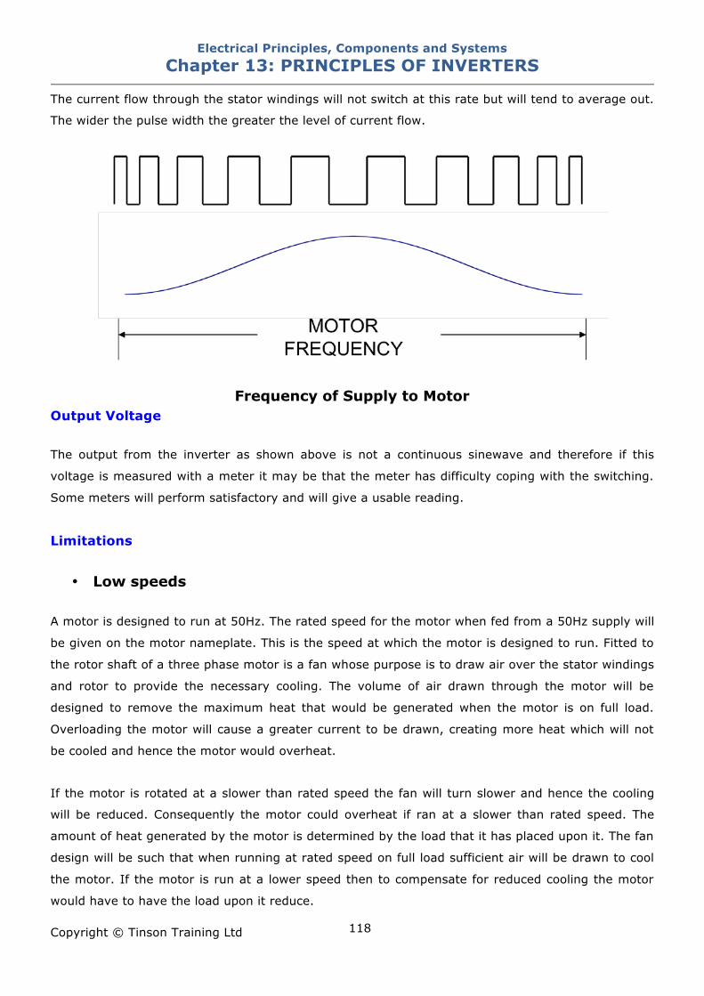
Electrical Principles, Components and Systems Chapter 13: PRINCIPLES OF INVERTERS
Copyright © Tinson Training Ltd
118
The current flow through the stator windings will not switch at this rate but will tend to average out.
The wider the pulse width the greater the level of current flow.
Frequency of Supply to Motor Output Voltage The output from the inverter as shown above is not a continuous sinewave and therefore if this
voltage is measured with a meter it may be that the meter has difficulty coping with the switching.
Some meters will perform satisfactory and will give a usable reading.
Limitations
• Low speeds A motor is designed to run at 50Hz. The rated speed for the motor when fed from a 50Hz supply will
be given on the motor nameplate. This is the speed at which the motor is designed to run. Fitted to
the rotor shaft of a three phase motor is a fan whose purpose is to draw air over the stator windings
and rotor to provide the necessary cooling. The volume of air drawn through the motor will be
designed to remove the maximum heat that would be generated when the motor is on full load.
Overloading the motor will cause a greater current to be drawn, creating more heat which will not
be cooled and hence the motor would overheat.
If the motor is rotated at a slower than rated speed the fan will turn slower and hence the cooling
will be reduced. Consequently the motor could overheat if ran at a slower than rated speed. The
amount of heat generated by the motor is determined by the load that it has placed upon it. The fan
design will be such that when running at rated speed on full load sufficient air will be drawn to cool
the motor. If the motor is run at a lower speed then to compensate for reduced cooling the motor
would have to have the load upon it reduce.
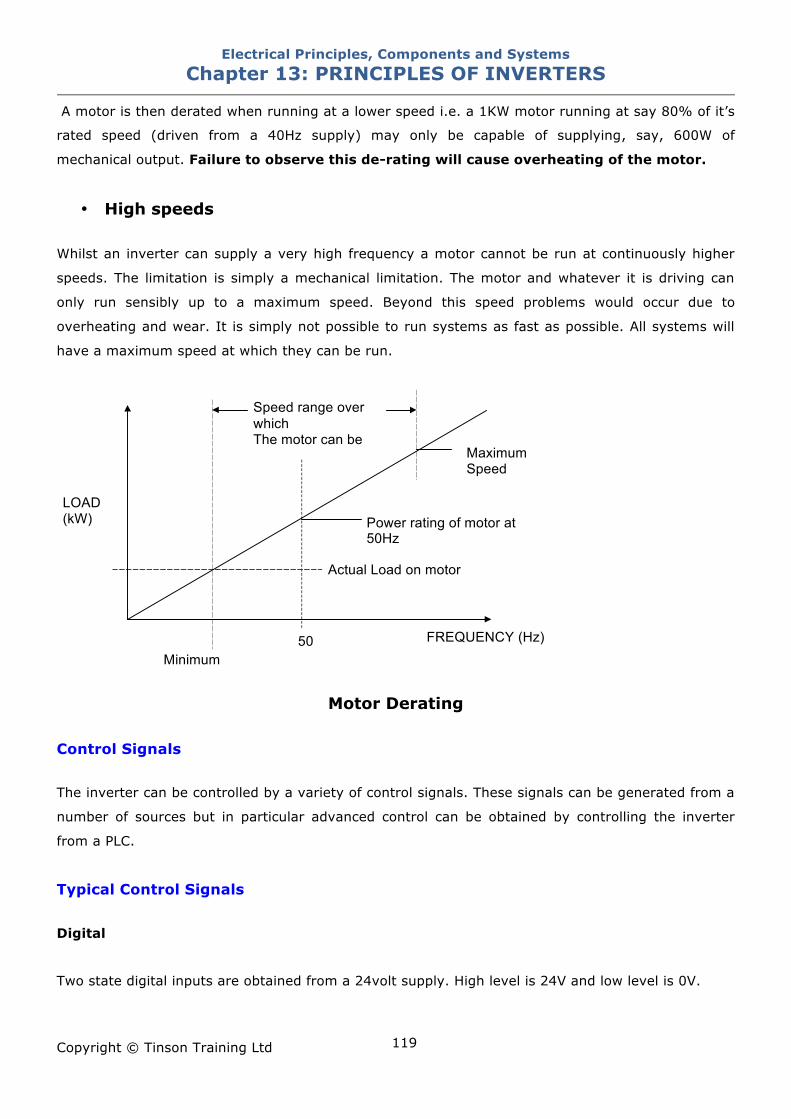
Electrical Principles, Components and Systems Chapter 13: PRINCIPLES OF INVERTERS
Copyright © Tinson Training Ltd
119
A motor is then derated when running at a lower speed i.e. a 1KW motor running at say 80% of it’s
rated speed (driven from a 40Hz supply) may only be capable of supplying, say, 600W of
mechanical output. Failure to observe this de-rating will cause overheating of the motor.
• High speeds
Whilst an inverter can supply a very high frequency a motor cannot be run at continuously higher
speeds. The limitation is simply a mechanical limitation. The motor and whatever it is driving can
only run sensibly up to a maximum speed. Beyond this speed problems would occur due to
overheating and wear. It is simply not possible to run systems as fast as possible. All systems will
have a maximum speed at which they can be run.
Motor Derating
Control Signals The inverter can be controlled by a variety of control signals. These signals can be generated from a
number of sources but in particular advanced control can be obtained by controlling the inverter
from a PLC.
Typical Control Signals Digital
Two state digital inputs are obtained from a 24volt supply. High level is 24V and low level is 0V.
LOAD (kW)
FREQUENCY (Hz) 50
Power rating of motor at 50Hz
Actual Load on motor
Minimum
Maximum Speed
Speed range over which The motor can be
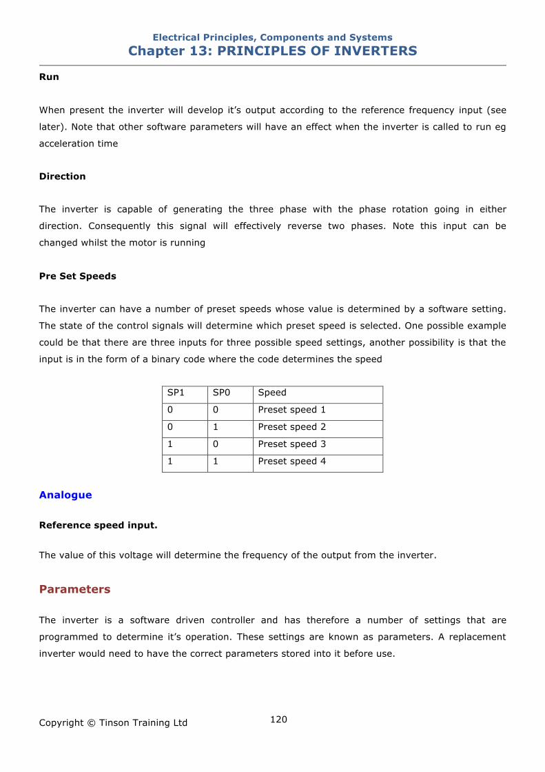
Electrical Principles, Components and Systems Chapter 13: PRINCIPLES OF INVERTERS
Copyright © Tinson Training Ltd
120
Run
When present the inverter will develop it’s output according to the reference frequency input (see
later). Note that other software parameters will have an effect when the inverter is called to run eg
acceleration time
Direction
The inverter is capable of generating the three phase with the phase rotation going in either
direction. Consequently this signal will effectively reverse two phases. Note this input can be
changed whilst the motor is running
Pre Set Speeds
The inverter can have a number of preset speeds whose value is determined by a software setting.
The state of the control signals will determine which preset speed is selected. One possible example
could be that there are three inputs for three possible speed settings, another possibility is that the
input is in the form of a binary code where the code determines the speed
SP1 SP0 Speed
0 0 Preset speed 1
0 1 Preset speed 2
1 0 Preset speed 3
1 1 Preset speed 4
Analogue Reference speed input.
The value of this voltage will determine the frequency of the output from the inverter.
Parameters The inverter is a software driven controller and has therefore a number of settings that are
programmed to determine it’s operation. These settings are known as parameters. A replacement
inverter would need to have the correct parameters stored into it before use.
Electrical Principles, Components and Systems Chapter 13: PRINCIPLES OF INVERTERS
Copyright © Tinson Training Ltd
121
Some examples of parameters
Current limit
The output current from the inverter is limited by the size of the output transistors. A parameter can
be set which will determine the maximum current that would be drawn before the inverter trips
Speed
It is likely that the inverter has a number of preset speeds that may be triggered by hardware
inputs. E.g. two inputs SP0 and SP1would have corresponding parameter settings to determine
these speeds.
Maximum frequency
To prevent a motor turning at a speed that may be too high, a maximum limit can be set so that the
output from the inverter will not go beyond that value.
Minimum frequency
To prevent a motor running at a too lower speed there can be set a minimum frequency that the
inverter will output. Frequencies below this value will not be output from the inverter
Acceleration time
When first starting an acceleration limit can be set to prevent the motor accelerating too fast. This
limit will be time and will be the time from 0Hz to maximum frequency set by the maximum
frequency parameter.
Deceleration time
To prevent the motor from slowing down too fast a deceleration limit can be set which will be the
time from maximum frequency to 0Hz
NOTE: Setting a small amount of acceleration and deceleration time is very useful to
remove harsh starting and stopping of the motor. This can reduce the wear on the drive
system
Electrical Principles, Components and Systems Chapter 13: PRINCIPLES OF INVERTERS
Copyright © Tinson Training Ltd
122
Motor Connections
If an inverter is fed from a single phase supply then the DC level produced internally is around
300V. If the inverter is fed from a three phase supply then the internal DC is around 600V. As a
result of this the output voltage of the inverter will change.
A single phase inverter (one fed from a single phase supply) will produce an output of 240V between
phases
A three phase inverter ( one fed from three phase supply) will produce an output voltage of 415V
between phases.
Consequently the connection of the motor will change. If the motor is intended to be connected in
star when connected direct on line (the windings require 240V across them) the following
connections would be made.
A motor driven by a single phase inverter will have to be connected in DELTA
A motor driven from a three phase inverter will have to be connected in STAR
A large power motor that is intended to be connected in Delta (the windings require
415V) could not be driven by a single phase inverter.
Electrical Principles, Components and Systems Chapter 13: PRINCIPLES OF INVERTERS
Copyright © Tinson Training Ltd
123
ON LINE EXERCISE
Click here to access Chapter 13: Inverters - On Line Exercises
Electrical Principles, Components and Systems Chapter 14: ELECTRICAL SAFETY
Copyright © Tinson Training Ltd
124
Chapter 14
Electrical Safety At the end of this section you will have an understanding of
• how injury is caused through electric shock
• the levels of current sufficient to cause harm
• all electrical dangers
• first aid treatment
• safe working practices
• the principles and importance of earthing
Electrical Principles, Components and Systems Chapter 14: ELECTRICAL SAFETY
Copyright © Tinson Training Ltd
125
Electrical Safety
The Dangers of Electricity Most people think of electricity as being dangerous by virtue of it’s ability to produce electric shock.
However there are many other dangers which include
(a) Electric shock
(b) Electric burn
(c) Fires of electrical origin
(d) Electric arcing
(e) Explosions started or caused by electricity
1. Electric Shock
Electric shock is the effect on the nervous system of passing electricity through the human body.
The current affects the normal control of the body muscles and the effects of this vary from a mild
tingling sensation to death.
Effects of Electric Shock Definition of Electric Shock
“A stimulation of nerve with a resulting contraction of muscles and feeling of concussion”
Whenever the human body comes into contact with a live electrical supply, (a voltage), then there is
a possibility that a circuit will be formed and that current will flow through the body, Current flowing
through the body produces the effect known as electric shock. The current may take multiple routes
through the body with differing intensities in various parts of the body. These will be difficult to
predict.
The minimum effect is the sensation of tingling or vibration. This may not be painful and if the
current flow ceases then the person is unlikely to suffer any problem. Higher levels of current would
cause a sensation that would be painful. If the levels are high enough muscles within the body will
contract and spasm producing a locked muscle in a state of contraction (technically referred to as
tetanus). This will induce severe pain within the individual. Violent muscle spasms can break or
dislocate bones.
Electrical Principles, Components and Systems Chapter 14: ELECTRICAL SAFETY
Copyright © Tinson Training Ltd
126
When current flows through a resistance heat is produced and therefore it is possible that the victim
suffers burns. These burns may be more apparent at the points of contact due to increased
resistance at these points. Generally the smaller the area of contact the greater the burning will be.
If current flows through greater areas of the body there is an increased possibility that internal
organs of the body will suffer from the affects of being burnt. Burns to internal organs such as the
liver or kidneys could cause failure of these organs.
When current flows through the heart and is of sufficient size it may affect and cause a disturbance
to the rhythm of the heart beat. Larger current levels can cause the heart to go into ventricular
fibrillation. This is uncoordinated contraction of the cardiac muscles in the ventricles in the heart
making them tremble rather than contract properly. If this condition continues for more than a few
seconds blood flow will cease and death may occur within a few minutes. Similarly if current passes
through the respiratory organs this may cause paralysis of the respiratory system and the victim
stops breathing. If either of the two problems are not rectified the victim dies.
Blood clots can occur in the smaller veins and arteries. Damage to the smaller vessels is often
followed by amputation.
There is also the possibility of damage to the central nervous system which can remain as a
permanent disability.
There are a range of progressive condition that potentially could occur some time after the shock
with potential lesions in the spinal cord or brain.
Temporary affects may include unconsciousness, amnesia and transient paralysis of the limbs.
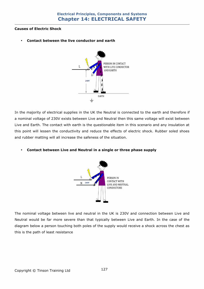
Electrical Principles, Components and Systems Chapter 14: ELECTRICAL SAFETY
Copyright © Tinson Training Ltd
127
Causes of Electric Shock
• Contact between the live conductor and earth
In the majority of electrical supplies in the UK the Neutral is connected to the earth and therefore if
a nominal voltage of 230V exists between Live and Neutral then this same voltage will exist between
Live and Earth. The contact with earth is the questionable item in this scenario and any insulation at
this point will lessen the conductivity and reduce the effects of electric shock. Rubber soled shoes
and rubber matting will all increase the safeness of the situation.
• Contact between Live and Neutral in a single or three phase supply
The nominal voltage between live and neutral in the UK is 230V and connection between Live and
Neutral would be far more severe than that typically between Live and Earth. In the case of the
diagram below a person touching both poles of the supply would receive a shock across the chest as
this is the path of least resistance
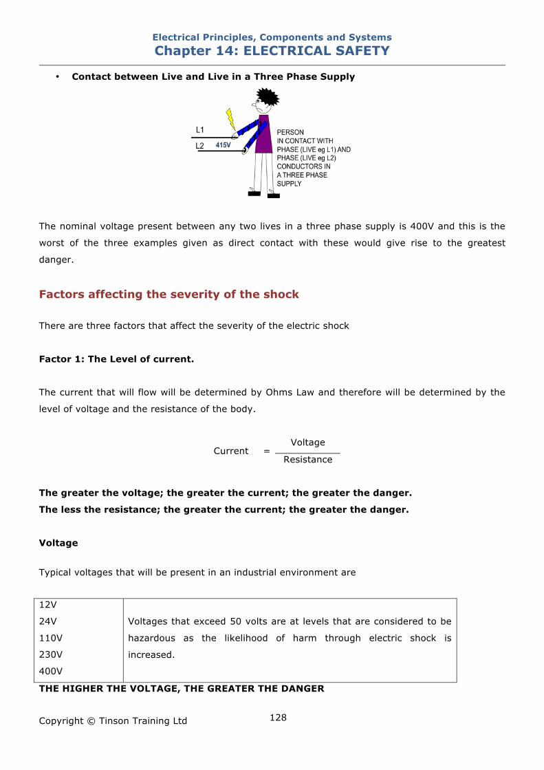
Electrical Principles, Components and Systems Chapter 14: ELECTRICAL SAFETY
Copyright © Tinson Training Ltd
128
• Contact between Live and Live in a Three Phase Supply
The nominal voltage present between any two lives in a three phase supply is 400V and this is the
worst of the three examples given as direct contact with these would give rise to the greatest
danger.
Factors affecting the severity of the shock
There are three factors that affect the severity of the electric shock
Factor 1: The Level of current.
The current that will flow will be determined by Ohms Law and therefore will be determined by the
level of voltage and the resistance of the body.
Voltage Current =
Resistance
The greater the voltage; the greater the current; the greater the danger.
The less the resistance; the greater the current; the greater the danger.
Voltage
Typical voltages that will be present in an industrial environment are
12V
24V
110V
230V
400V
Voltages that exceed 50 volts are at levels that are considered to be
hazardous as the likelihood of harm through electric shock is
increased.
THE HIGHER THE VOLTAGE, THE GREATER THE DANGER
Electrical Principles, Components and Systems Chapter 14: ELECTRICAL SAFETY
Copyright © Tinson Training Ltd
129
THE PUBLIC ELECTRICITY SUPPLY IN THE UK IS RATED AT 230V AND SHOULD ALWAYS BE
CONSIDERED AS POTENTIALLY FATALLY DANGEROUS.
Body Resistance
This body resistance varies according to
• the physical condition of the body
• age
• situation
• weather
It is not possible to predict the resistance of the body and therefore it is not possible to predict
exactly what will happen to the victim. Body resistance will vary with the amount of moisture. A
person is generally at greater risk in a damp or humid environment but perspiration can also
contribute to this moisture
Effects of the levels of current
Current in mA Effect
0.5 – 2.0 Threshold of perception with mild tingling
2-10 Painful sensation increasing with current
10-25 Cramp and inability to let go. Increase in blood pressure. Danger of asphyxiation
from respiratory muscular contraction
15-80 Sever muscular contraction sometimes involving bone fracture. Increased blood
pressure. Loss of consciousness from heart and/or respiratory failure
Over 80 Burns at the point of contact. Death from ventricular fibrillation
IT TAKES VERY LITTLE CURRENT TO CAUSE HARM !!
Increased currents will flow when the person is in good contact with earth or earthed equipment and
/ or when the person is in damp or wet conditions.
Electrical Principles, Components and Systems Chapter 14: ELECTRICAL SAFETY
Copyright © Tinson Training Ltd
130
Factor 2: The route that the current takes
The route that the current takes through the body will be determined by the points of contact
although as previously stated will be unpredictable.
If a person brushes the back of their hand across a supply then the current flow could be across the
hand and could be quite high and therefore result in burns but may not be fatal. If the points of
contact are, say, from hand to hand then the current flow would be across the chest and could be
through the heart.
Factor 3: The time for which the current flows.
The longer that the current flows for, the more harm is done. Certainly burning will continue for the
period of current flow and therefore heat and burning will increase. A person who makes contact for
a very short period of time may well tolerate a high current for that time. This problem is
highlighted when a person touches a supply but the hand and arm muscles spasm and the person
grips hold of the supply. This is out of control of the victim but the effect would be to lengthen the
time for which the current is flowing.
If a person is found in contact with an electrical supply, in the process of receiving electric shock and
is unable to let go of the conductor it is imperative to disconnect the source of the supply
immediately. The longer this situation exists the more harm will come to the victim.
If the source of the supply cannot quickly be recognised then another method should be used to
physically remove the person from the supply. This could be in the form of using an insulated item
(piece of wood) to ‘knock or push’ the person away from the supply.
AC versus DC
DC (direct current) is more likely to induce (tetanus) the freezing of the body and cause an
individual to be locked onto an electrical supply thus prolonging the ‘shock’ with greater risk of
injury.
AC is more likely to cause fibrillation of the heart. A stopped heart has a greater chance of starting
and recovering whereas fibrillation is a condition that is not so easy to recover from.
Electrical Principles, Components and Systems Chapter 14: ELECTRICAL SAFETY
Copyright © Tinson Training Ltd
131
2. Electric Burns Electricity passing through any resistance liberates heat energy. The element of an electric fire for
example has resistance to the flow of current and heats up as a consequence. In the same way,
human tissue resists the flow of electric current and the heat liberated causes burns. Such burns are
commonly associated with electric shock and often occur at the point of contact with the source of
electricity.
In certain circumstances it is possible to suffer electrical burns without being in contact with an
electrical source. High powered radio transmitters and microwave ovens, for example, can produce
electrical burns due to high frequency electromagnetic waves.
3. Electrical Explosion
This literally means blowing a piece of electrical equipment apart due to electrical overload. A 12V
car headlight, for example, will explode if mains voltage is connected across it.
4. Explosion Initiated by Electricity
Certain vapours, gases and fine dusts may explode if triggered by even tiny electric sparks.
Examples are petrol, ether, methane, flour dust and talcum powder.
5. Arcing
The air is normally a good insulator, but under certain circumstances this insulation is broken down
and sparks jump across air gaps. This is known as arcing. The most spectacular arcing is lightning,
but you can see the effect quite clearly when you connect up a car battery. Arcing has it’s own
particular dangers
a) electrical burns
b) ultra violet radiation - this gives symptoms similar to that of sunburn. The
radiation from an arc welder can be particularly dangerous to the eyes.
c) infra red heat or heat radiation - this will burn in the same way as putting
your hand close to an electric fire
d) burns due to molten metal particles which often accompany arcing
6. Fire Caused by Electricity
Fires present a number of dangers. The most obvious is burning. But smoke or toxic fume inhalation
are at least as dangerous. The main causes of fire are
Electrical Principles, Components and Systems Chapter 14: ELECTRICAL SAFETY
Copyright © Tinson Training Ltd
132
a) overheating of cables and electrical equipment due to the passage of too
much current
b) current leaking due to poor or inadequate insulation
c) overheating of inflammable materials placed too close to electrical equipment
d) the ignition of flammable materials by arcing, sparking or the scattering of
hot particles from electrical equipment
Action in the Event of Electric Shock Break contact with the supply by switching off, removing plug or by wrenching cable free. If this
should not be possible, stand on some insulating material, such as dry wood or rubber and break
contact by pushing the casualty free. In a place of work a First Aider should be summoned in the
event of a person suffering from electric shock.
Treatment for Electric Shock Reference should be made to an appropriate First Aid manual
• St Johns Ambulance
• St Andrews Ambulance Association
• The British Red Cross Society
Slight Shock
• Reassure the casualty and make them comfortable
• If in doubt refer to a medical practitioner
• Report the accident to the appropriate personnel
Burns
• Cool the tissue with cold water or other non flammable fluid close to hand
• Remove any smouldering clothing. Clothing that has caught fire but has cooled need not be
removed
• Remove anything of a constrictive nature; rings, bangles, belts and boots
• Reassure the casualty
• Dress wounds to prevent infection
• Give sips of fluid to the casualty if conscious
• If the casualty is severely burned arrange for them to be taken to hospital without delay
Electrical Principles, Components and Systems Chapter 14: ELECTRICAL SAFETY
Copyright © Tinson Training Ltd
133
• Report the accident to the appropriate personnel
Abrasions
• Clean and dress the wound to prevent further infection
• Reassure the casualty
• Arrange for medical help if necessary
• Report the accident to the appropriate personnel
Casualty Unconscious but breathing
• Loosen clothing about the neck, chest, and waist and place casualty in the recovery position
• Keep a constant check on breathing and pulse
• Arrange for medical help if necessary
• Report the accident to the appropriate personnel
Electrical Principles, Components and Systems Chapter 14: ELECTRICAL SAFETY
Copyright © Tinson Training Ltd
134
Safe Working Practices Introduction Electricity is a killer. Make no mistake.
Death or injury can occur if you work on a piece of electrical equipment and you
• are not adequately trained in the dangers of working on such equipment
• do not have the necessary knowledge of electricity and the equipment being worked on
• are careless and negligent
• do not observe safety precautions
Remember that you do not only endanger yourself but also others. Causing death or suffering to
others can not only be traumatic but could also have severe legal implications as a result of a breach
of health and safety law.
Be extremely vigilant, disciplined and thorough. Do not take short cuts even if you are instructed to
or under pressure from others. It is you who could be responsible should something go wrong.
Working on Live Systems Making tests on live equipment
Electrical circuits may need to be tested live with the power applied. The Electricity at Work
Regulations 1989 does make allowances for this activity by stating that equipment can be live when
work is being carried out if it is unreasonable for it to be dead. Certain aspects of fault finding do
require the system to be live. This is a hazardous situation that could result in a fatality. Remember
if you can make an equivalent test with the circuit dead that method should be used in preference to
a live circuit test.
Before making any tests on a live circuit you must
• BE AWARE OF ALL THE VOLTAGES THAT YOU CAN ENCOUNTER WHILST WORKING
ON A SYSTEM.
Electrical Principles, Components and Systems Chapter 14: ELECTRICAL SAFETY
Copyright © Tinson Training Ltd
135
Typically 12V DC
24V DC
110V AC
230V AC
400V AC
• BE AWARE OF THE VOLTAGES THAT MAY BE GENERATED WITHIN A CIRCUIT THAT
MAY BE HIGHER THEN AN INCOMING SUPPLY VOLTAGE
Typically through step up transformers
• AT ALL TIMES YOU MUST BE FULLY ALERT TO THE PARTS THAT YOU ARE TOUCHING
Avoid leaning on parts
Be totally vigilant concerning any part that you touch for support
• ENSURE THAT ANY TOOLS AND EQUIPMENT THAT YOU USE ARE IN GOOD WORKING
CONDITION AND OF THE CORRECT TYPE AND STANDARD FOR THE TASK BEING
UNDERTAKEN
• IF IT IS APPROPRIATE DISCONNECT POWER, CONNECT THE TEST INSTRUMENT IN
SUCH A WAY THAT IT CAN BE OPERATED HANDS FREE. POWER CAN BE
RECONNECTED AND THE INSTRUMENT READ WITHOUT CONTACT. BEFORE
REMOVING THE INSTRUMENT DISCONNECT THE POWER.
• IF A CIRCUIT IS INTERRUPTED TO MAKE A TEST ENSURE THAT IT IS RECONNECTED
CORRECTLY.
Note connections before removal if necessary
• ALWAYS ENSURE THAT EARTHS ARE CONNECTED
Any error that you make may endanger the lives of others.
Electrical Principles, Components and Systems Chapter 14: ELECTRICAL SAFETY
Copyright © Tinson Training Ltd
136
Parts replacement on live systems
There are very rare situations where parts would be disconnected, removed and replaced on a
system whilst it is live. These would need to be have been identified in advance, thorough risk
assessments carried out and very special procedures would need to be in place.
IN VIRTUALLY ALL SCENARIOS POWER WOULD BE DISCONNECTED FROM A CIRCUIT
BEFORE DISCONNECTING, REMOVING AND REPLACING PARTS.
Electrical Isolation
The way in which the electrical supply is connected to the equipment will affect the certainty of
whether the supply is disconnected. Equipment fed from a connector such as plug can easily be
observed as being disconnected and there ought to be little doubt that the equipment being worked
on is disconnected from the supply. Switchable isolators can sometimes be difficult to locate or
identify. These isolators should be easily accessible and clearly marked indicating the equipment to
which it relates.
Isolation
The term isolation is defined here as disconnecting the supply and ensuring that it stays
disconnected for the duration of the work being carried out. This is clearly to prevent inadvertent
switching on of the supply at a time when the person working on the equipment is not aware. A
typical scenario could be that the person working on the equipment leaves the work area (perhaps
to collect parts or tools) and during the absence someone turns the equipment back on. It is hard to
believe but there is always a possibility that someone with inadequate knowledge may indeed switch
the supply on whilst the person is working.
Precautions should be taken to prevent this reconnection of the supply during this time. Such
precautions could include the use of lockable isolators which can be locked in the ‘off’ position. The
person working on the equipment uses a padlock to lock the supply off and they hold the key to that
padlock. In some instances where several people are working on equipment, the use of clasps that
allow the padlocks of all those working to be fitted is good practice.
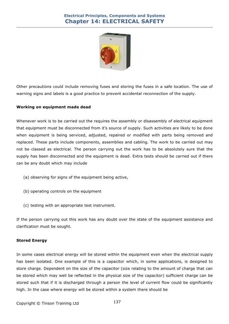
Electrical Principles, Components and Systems Chapter 14: ELECTRICAL SAFETY
Copyright © Tinson Training Ltd
137
Other precautions could include removing fuses and storing the fuses in a safe location. The use of
warning signs and labels is a good practice to prevent accidental reconnection of the supply.
Working on equipment made dead
Whenever work is to be carried out the requires the assembly or disassembly of electrical equipment
that equipment must be disconnected from it’s source of supply. Such activities are likely to be done
when equipment is being serviced, adjusted, repaired or modified with parts being removed and
replaced. These parts include components, assemblies and cabling. The work to be carried out may
not be classed as electrical. The person carrying out the work has to be absolutely sure that the
supply has been disconnected and the equipment is dead. Extra tests should be carried out if there
can be any doubt which may include
(a) observing for signs of the equipment being active,
(b) operating controls on the equipment
(c) testing with an appropriate test instrument.
If the person carrying out this work has any doubt over the state of the equipment assistance and
clarification must be sought.
Stored Energy
In some cases electrical energy will be stored within the equipment even when the electrical supply
has been isolated. One example of this is a capacitor which, in some applications, is designed to
store charge. Dependent on the size of the capacitor (size relating to the amount of charge that can
be stored which may well be reflected in the physical size of the capacitor) sufficient charge can be
stored such that if it is discharged through a person the level of current flow could be significantly
high. In the case where energy will be stored within a system there should be
Electrical Principles, Components and Systems Chapter 14: ELECTRICAL SAFETY
Copyright © Tinson Training Ltd
138
(a) warning labels indicating this and
(b) an automatic means for this to be discharged when the power is removed
Replacing faulty items
• POWER SHOULD ALWAYS BE REMOVED BEFORE ANY PART IS DISCONNECTED
• IDENTIFY THE METHOD OF ISOLATING A MACHINE FROM IT’S SUPPLY
Test the supply with a meter to ensure no voltage is present (having first established that the
test instrument is working correctly)
• ADEQUATE PRECAUTIONS SHOULD BE TAKEN TO ENSURE THAT THE SUPPLY
CANNOT INADVERTENTLY BE RECONNECTED
Lock the isolator in the off position if this has been the method of disconnection. If the
isolation method is done by removing a plug give some consideration to preventing the plug
from being re-inserted by someone else.
• BE AWARE OF ANY VOLTAGES THAT WILL REMAIN IN A CIRCUIT WHEN THE MAINS
POWER IS REMOVED
Specifically on capacitors that have been charged with high voltage DC
• NOTE CONNECTIONS BEFORE THEY ARE REMOVED
If necessary verify connections with a schematic diagram
• NOTE ANY DAMAGE TO CABLES OR OTHER COMPONENTS
Signs of overheating
Cut / damaged insulation
• WHEN POWER IS RECONNECTED OBSERVE FOR ANY SIGNS OF A PROBLEM
Electrical Principles, Components and Systems Chapter 14: ELECTRICAL SAFETY
Copyright © Tinson Training Ltd
139
Smoking
Sparking
Malfunction of machine
NOTE IF YOUR BUSINESS / COMPANY / EMPLOYER HAS A SPECIFIC ISOLATION
PROCEDURE THIS SHOULD BE ADHERED TO AT ALL TIMES.
Earthing The purpose of Earthing
In the United Kingdom the neutral of the supply is usually connected to earth. If therefore there is
230V between Live and Neutral there will be 230 V between Live and any earthed point. This in itself
creates a danger as a person may well be in contact with earth (unless they are deliberately
insulated from earth with good rubber soled shoes or standing on rubber matting) and they would
therefore only need to make one point of contact with the Live.
Wherever a live supply is in the vicinity of exposed electrical conductors (eg pipes, cabinets, chassis
etc) the exposed conductors must be earthed. Without this earth it could be possible for a live
conductor to inadvertently come into contact with the metal thus making it live. This would, of
course, be a lethal hazard for anybody to come into contact with, since it would not be expected
that the metalwork would present a danger. With the metalwork earthed any contact from a live
source would cause over-current and the operation of the protective device such as fuse or circuit
breaker. The resistance to earth through this path should be very low such that a large current tries
to flow and the protective device (fuse or circuit breaker) operates almost simultaneously. For this
reason the earth connection should be very securely made ensuring that solid contact is made with
bare metal. It may well be necessary to ensure that any paint has been removed to enhance this
contact. If for any reason this connection is removed it should be replaced before the equipment is
turned on.
What not to earth.
The answer is simply a human body when it has made contact with a live supply. Since a body will
normally be in contact with earth to some degree (i.e. standing on the ground) if that person
touches a live supply a circuit will be formed with the path to earth. The better the earth connection
the lower the resistance of the path and consequently the greater the current. It is therefore useful
to inhibit the connection to earth wherever this is feasible. This can be achieved using thick rubber
Electrical Principles, Components and Systems Chapter 14: ELECTRICAL SAFETY
Copyright © Tinson Training Ltd
140
soled shoes or rubber mats. Avoid making good connections by wearing earth straps or holding
earthed conductors.
Electrical Principles, Components and Systems Chapter 14: ELECTRICAL SAFETY
Copyright © Tinson Training Ltd
141
ON LINE EXERCISE
Click here to access Chapter 14: Electrical Safety - On Line Exercises
Electrical Principles, Components and Systems Chapter 15: CABLES AND PROTECTION
Copyright © Tinson Training Ltd
142
Chapter 15
Cables and Protection At the end of this section you will have an understanding of
• the factors affecting the choice of cables
• the principles of protection
• the operation of fuses
• the operation of miniature circuit breakers
• the operation of residual current circuit breakers
Electrical Principles, Components and Systems Chapter 15: CABLES AND PROTECTION
Copyright © Tinson Training Ltd
143
Cables and Protection Cables and Cable Ratings There is huge range of cables available to be used within any electrical system from the distribution
of electrical supplies overground and underground, distribution of electrical supplies within buildings
(industrial, commercial, business and residential), wiring of electrical control systems, carrying
electrical data, signals from sensors etc. For any specific application there are factors that need to
be taken into account to help decide the most appropriate cable for the task. In electrical control
systems the most common cable found will be copper pvc insulated stranded cable.
Conductor Cross Sectional Area The greater the cross sectional area the more current a cable will be capable of passing.
Insulation Some type of insulation will be damaged at temperatures where no damage would occur to others.
For example a p.v.c insulated cable at 2.5 square mm will be rated at 24A whereas the same size of
mineral insulated conductor will be rated at 43A
Ambient Temperature If the cable is installed in a hot environment it will not be able to dissipate the heat as easily as it
would in cooler surroundings and will operate at higher temperatures.
Type of Protection In the event of a fault or overload, the speed at which the protection device operates may vary
depending upon the type of device used. The longer it takes a device to operate the greater the
increase in temperature. Cables protected by rewireable fuses will be rated lower than those
protected by HBC fuses or circuit breakers.
Grouping Cables run together will not be able to radiate the heat and conduct as freely as if they were run
separately. Cables run in groups are rated lower than those ran singularly.
Electrical Principles, Components and Systems Chapter 15: CABLES AND PROTECTION
Copyright © Tinson Training Ltd
144
Disposition The physical area in which the cables lay may affect the ability to radiate heat. For example cables
laid in moist earth will radiate heat more readily than one laid in air.
Type of Sheath If the cable is protected with an outer sheath for protection purposes this will hinder the ability to
radiate heat.
Contact with Thermal Insulation A cable laid in an area surrounded by thermal insulation will not be able to radiate heat and will
need to be rated lower.
General Guidelines Cabling can be observed for signs of damage. Damage may constitute physical damage such as a
cable being trapped with the insulation cut. This may expose the conductor with the possibility of
coming into contact with another conductor or human limbs. Generally damaged cables should be
replaced with a cable of the same rating and type. Overheating of cables may be observed by
damage to the insulation. Again extensive overheating can damage the insulation to the extent that
the conductor is exposed. If overheating has occurred the cause should be ascertained.
Overheating may occur when
• a motor has seized or become jammed
• the cable is the wrong size
• the ambient temperature has risen significantly
• there has been a short circuit
In all instances of cable overheating the cause should be rectified such that it does not occur again.
Preparing Cables for Termination
Whatever type of cable is being used the cable ends are terminated at a connector whether that it is
plug, socket, terminal rail, equipment or component terminals. Correct and safe preparation of
cables is important. The main aspect of cable preparation is to remove outer and inner insulation
such that bare conductor is exposed for insertion into a terminal.
Electrical Principles, Components and Systems Chapter 15: CABLES AND PROTECTION
Copyright © Tinson Training Ltd
145
Removing Outer Insulation or Sheath
The use of the correct tool for removing the outer sheath is helpful to prevent any damage to the
insulation of the cores. This tool has a cutter which is applied with sufficient pressure to cut the
outer sheath but not the inner cores. If any damage occurs to the inner core insulation the end
should be cut off and the process restarted.
Removing Inner Core Insulation When removing insulation from cores to expose the conductor it is important not to damage the
inner conductor. Stranded cable should not lose strands through this insulation stripping process. If
any damage occurs to the conductors the ends should be cut off and the process restarted. Correct
wire strippers should be used to help with this process.
Electrical Principles, Components and Systems Chapter 15: CABLES AND PROTECTION
Copyright © Tinson Training Ltd
146
Introduction to Over Current Protection Electrical systems need to be protected electrically from overheating due to excessive current flow
which in turn will cause
• fires and a risk to human life
• damage to equipment
• damage to cabling
Any current excessive in nature with regard to a specific situation can cause a conductor to become
hot. Such overheating can continue until serious risks of injury and death are very real. The
overheating of any conductor can give rise to fires which can lead to catastrophic situations and
multiple casualties and deaths. It is this risk to human life that is the overriding factor in ensuring
that excessive currents cannot flow in any conductor in an electrical system. The Electricity at Work
Regulations 1989 state that ALL conductors in an electrical systems have to be protected from
excessive current.
Secondary to the risk to life is the potential damage to equipment that can occur as a result of
excessive current.
For a variety of reasons electrical equipment can develop problems which result in damage to
equipment which might otherwise have been prevented. In a simple example it might be that the
movement of a motor is hindered by an obstacle that has fallen. The motor will attempt to drive
against this object and draw more current in an attempt to do so. This extra current could then
cause the cables and the motor to overheat. This overheating can only continue for so long until a
serious problem develops. Serious problems occur when materials melt due to excessive
temperatures. Such materials are the insulation on the windings of motors or transformers. This will
short out sections of a coil, which in turn will lower the coil resistance and create further current and
further overheating. Obviously this destruction escalates until sections of the winding melt. During
this process, the whole of the body of the unit become increasingly hot and due to expansion
moving parts may cease. Ultimately the results of overheating have caused serious and expensive
problems. Cables themselves will suffer when excessive currents are allowed to pass. The
overheating will cause in the first instance the insulation to melt and finally the conductor in the
cable to melt. Quite simply it is far better to prevent this build up of excessive current and prevent
this damage.
Protection is easily achieved by breaking the supply to a circuit when overcurrent is detected.
Electrical Principles, Components and Systems Chapter 15: CABLES AND PROTECTION
Copyright © Tinson Training Ltd
147
Fuses A fuse operates by disconnecting the supply through melting the fuse element
Fusing Factor A fuse will have to pass, without problem, the normal operating current of the circuit. This will be
termed the current rating of the fuse. The fuse should be capable of passing this current indefinitely.
The minimum fusing current will be the current that will cause the fuse to melt.
Minimum Fusing Current The Ratio
Current Rating is known as the Fusing Factor
Principle of Action Every conductor is heated to a greater or less extent by the passage of current through it, the
heating increasing with the square of the current and the resistance of the conductor.
E.g. If the resistance of a cable doubles the heat doubles. If the current through a cable doubles the
heat will quadruple
If part of a circuit is reduced in cross sectional area it will, in normal circumstances, run hotter than
the main part of the circuit. On the occurrence of an excessive current it will heat up much more
quickly than the remainder of the circuit. If matters are arranged so that the reduced section melts
when excessive current occurs, the molten metal is vaporised and an arc results. If the arc is
extinguished the circuit is broken. A fuse is normally designed to carry out these operations which is
commonly called blowing a fuse.
Anti surge fuses Anti surge fuses are designed to withstand a higher than normal current for a limited period of time
before blowing. These are used in some electronic equipment when there may be a high surge
current at switch on. During this time this is acceptable and it would be impractical for the fuse to
blow. After this initial surge the current settles down to the normal operating current and currents
continuously above this need to be prevented. In other words the surge current is acceptable for
short period but not for sustained periods. The element of these fuses is constructed from a spring
like coil attached to the fuse wire within the tube. A typical example of surge protection is ten times
the current for 10mS.
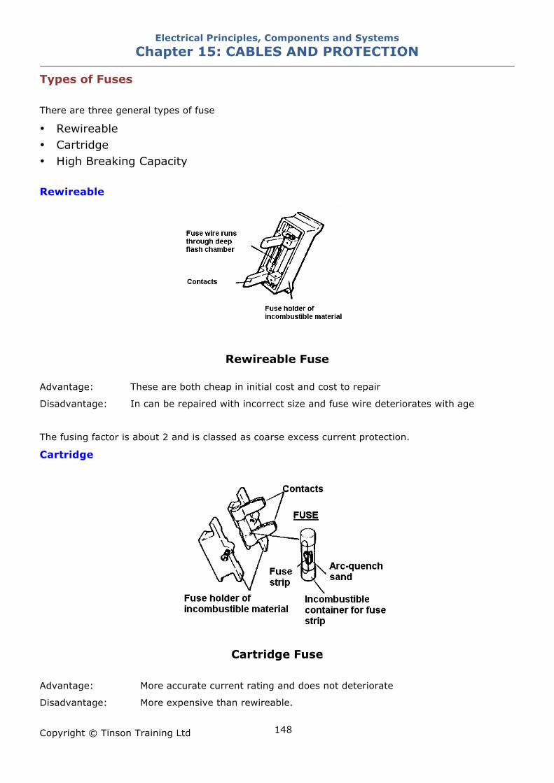
Electrical Principles, Components and Systems Chapter 15: CABLES AND PROTECTION
Copyright © Tinson Training Ltd
148
Types of Fuses There are three general types of fuse
• Rewireable • Cartridge • High Breaking Capacity Rewireable
Rewireable Fuse
Advantage: These are both cheap in initial cost and cost to repair
Disadvantage: In can be repaired with incorrect size and fuse wire deteriorates with age
The fusing factor is about 2 and is classed as coarse excess current protection.
Cartridge
Cartridge Fuse
Advantage: More accurate current rating and does not deteriorate
Disadvantage: More expensive than rewireable.
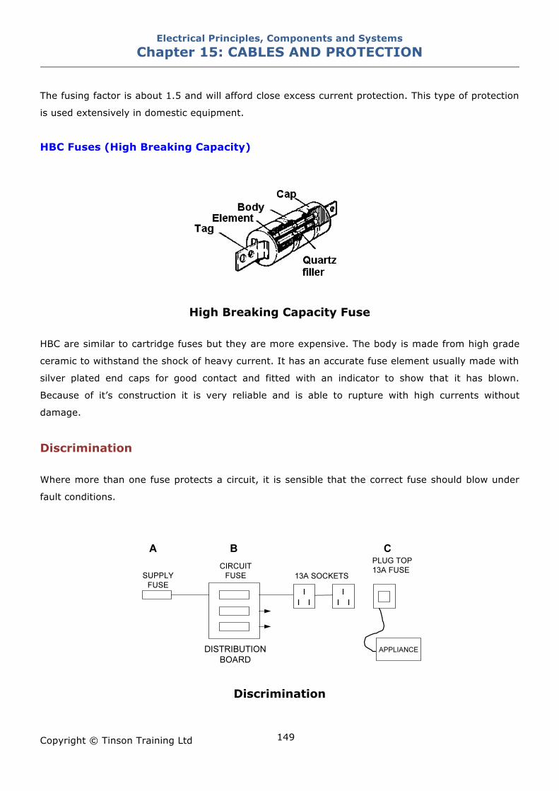
Electrical Principles, Components and Systems Chapter 15: CABLES AND PROTECTION
Copyright © Tinson Training Ltd
149
The fusing factor is about 1.5 and will afford close excess current protection. This type of protection
is used extensively in domestic equipment.
HBC Fuses (High Breaking Capacity)
High Breaking Capacity Fuse HBC are similar to cartridge fuses but they are more expensive. The body is made from high grade
ceramic to withstand the shock of heavy current. It has an accurate fuse element usually made with
silver plated end caps for good contact and fitted with an indicator to show that it has blown.
Because of it’s construction it is very reliable and is able to rupture with high currents without
damage.
Discrimination Where more than one fuse protects a circuit, it is sensible that the correct fuse should blow under
fault conditions.
Discrimination
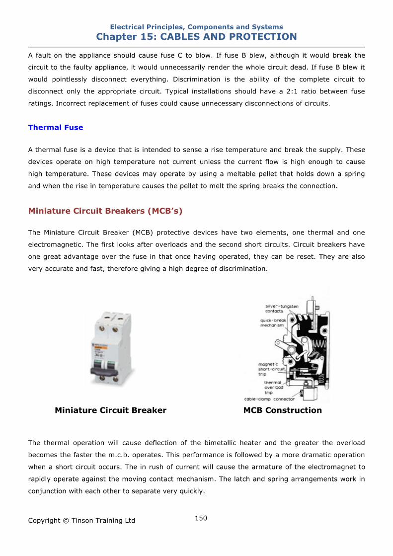
Electrical Principles, Components and Systems Chapter 15: CABLES AND PROTECTION
Copyright © Tinson Training Ltd
150
A fault on the appliance should cause fuse C to blow. If fuse B blew, although it would break the
circuit to the faulty appliance, it would unnecessarily render the whole circuit dead. If fuse B blew it
would pointlessly disconnect everything. Discrimination is the ability of the complete circuit to
disconnect only the appropriate circuit. Typical installations should have a 2:1 ratio between fuse
ratings. Incorrect replacement of fuses could cause unnecessary disconnections of circuits.
Thermal Fuse
A thermal fuse is a device that is intended to sense a rise temperature and break the supply. These
devices operate on high temperature not current unless the current flow is high enough to cause
high temperature. These devices may operate by using a meltable pellet that holds down a spring
and when the rise in temperature causes the pellet to melt the spring breaks the connection.
Miniature Circuit Breakers (MCB’s) The Miniature Circuit Breaker (MCB) protective devices have two elements, one thermal and one
electromagnetic. The first looks after overloads and the second short circuits. Circuit breakers have
one great advantage over the fuse in that once having operated, they can be reset. They are also
very accurate and fast, therefore giving a high degree of discrimination.
Miniature Circuit Breaker MCB Construction
The thermal operation will cause deflection of the bimetallic heater and the greater the overload
becomes the faster the m.c.b. operates. This performance is followed by a more dramatic operation
when a short circuit occurs. The in rush of current will cause the armature of the electromagnet to
rapidly operate against the moving contact mechanism. The latch and spring arrangements work in
conjunction with each other to separate very quickly.
Electrical Principles, Components and Systems Chapter 15: CABLES AND PROTECTION
Copyright © Tinson Training Ltd
151
Operating Characteristics
The rated value of the MCB is the value of current that they circuit breaker can pass indefinitely ie a
10A breaker will pass 10A forever.
A circuit breaker will trip when the current reaches a value for a period of time. The values of
current that would cause instantaneous operation of the circuit breaker is shown in the tables. It can
be seen that the type B is the most sensitive with type D being the least. Therefore circuits with
equipment that take large surge currents at switch on would use Type D, whereas equipment with
not so large surge currents would take Type C and equipment and circuits with the least value of
surge current would use Type B. Equipment that takes a large surge currents as normal operation
do not want to trip circuit breakers at start up and therefore Type C and D are used in these
applications.
Reference to BS EN 60898 Type B Circuit Breakers would give the following information in relation to
the tripping time versus level of current.
10A Breaker
Lowest value to trip the breaker is approx 18A and would trip after 10,000 secs (167 minutes)
20A would give a tripping time of 150secs
30A would give a tripping time of 35 secs
40A would give a tripping time of 20secs
Instantaneous tripping would occur at a current level of 50A
The higher the level of current flowing then the shorter the tripping time.
The tables shown state the instantaneous tripping times for Types B,C and D circuit breakers.
The following tables are used for illustrative purposes only to further explain the principles of circuit
breakers and should not be used for reference purposes. Consult the appropriate standard for
reliable and current data.
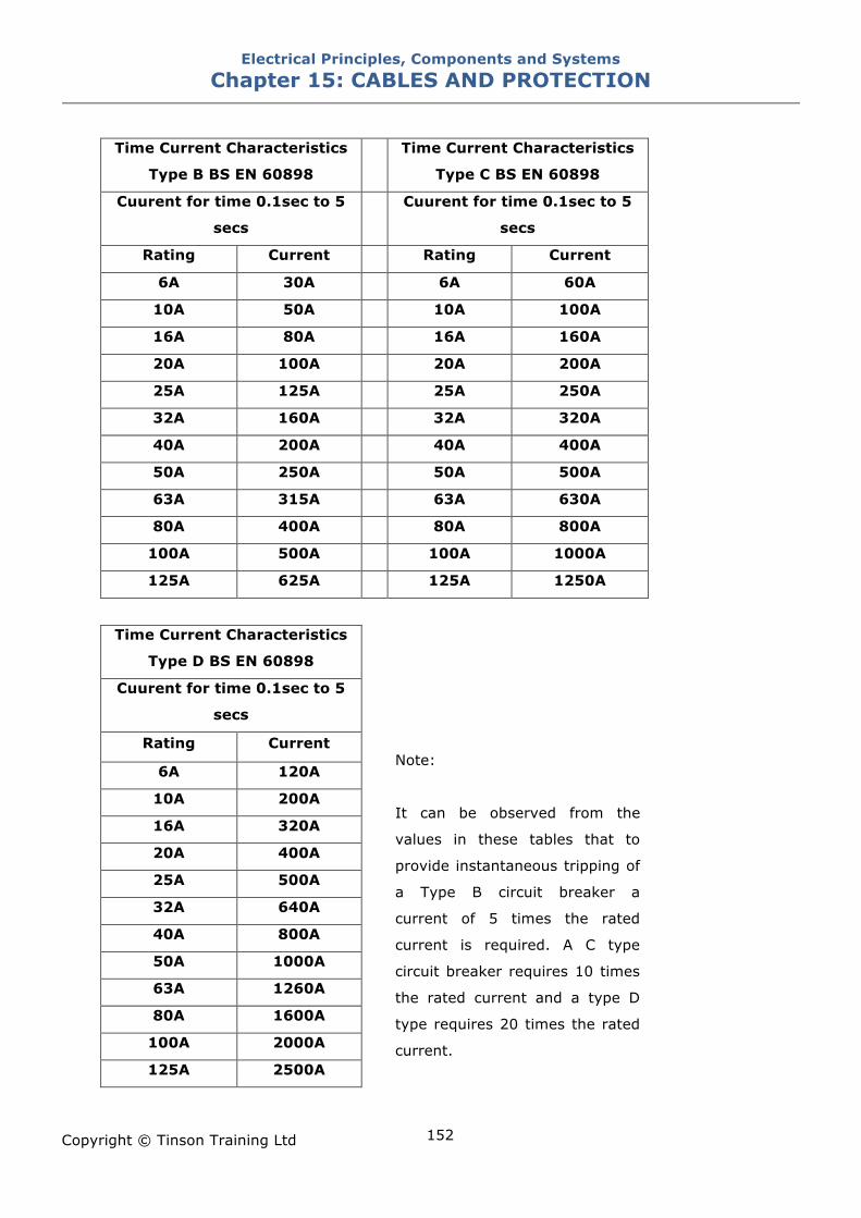
Electrical Principles, Components and Systems Chapter 15: CABLES AND PROTECTION
Copyright © Tinson Training Ltd
152
Time Current Characteristics
Type B BS EN 60898
Time Current Characteristics
Type C BS EN 60898
Cuurent for time 0.1sec to 5
secs
Cuurent for time 0.1sec to 5
secs
Rating Current Rating Current
6A 30A 6A 60A
10A 50A 10A 100A
16A 80A 16A 160A
20A 100A 20A 200A
25A 125A 25A 250A
32A 160A 32A 320A
40A 200A 40A 400A
50A 250A 50A 500A
63A 315A 63A 630A
80A 400A 80A 800A
100A 500A 100A 1000A
125A 625A 125A 1250A
Time Current Characteristics
Type D BS EN 60898
Cuurent for time 0.1sec to 5
secs
Rating Current
6A 120A
10A 200A
16A 320A
20A 400A
25A 500A
32A 640A
40A 800A
50A 1000A
63A 1260A
80A 1600A
100A 2000A
125A 2500A
Note:
It can be observed from the
values in these tables that to
provide instantaneous tripping of
a Type B circuit breaker a
current of 5 times the rated
current is required. A C type
circuit breaker requires 10 times
the rated current and a type D
type requires 20 times the rated
current.
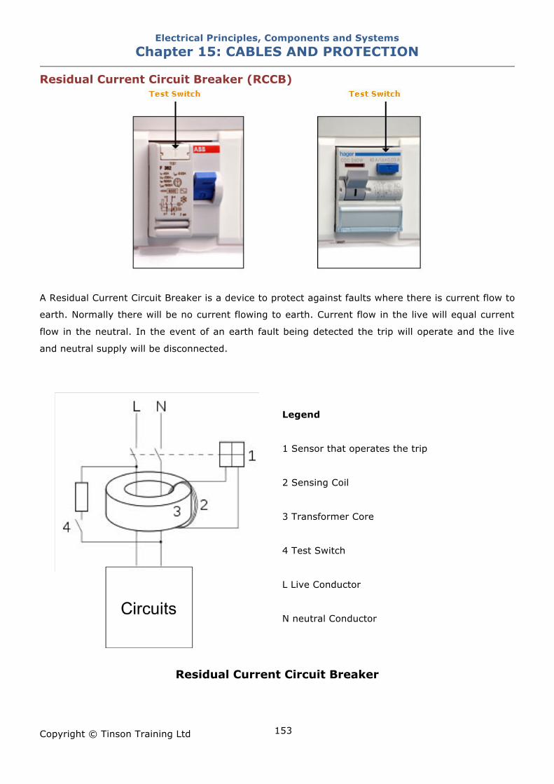
Electrical Principles, Components and Systems Chapter 15: CABLES AND PROTECTION
Copyright © Tinson Training Ltd
153
Residual Current Circuit Breaker (RCCB)
A Residual Current Circuit Breaker is a device to protect against faults where there is current flow to
earth. Normally there will be no current flowing to earth. Current flow in the live will equal current
flow in the neutral. In the event of an earth fault being detected the trip will operate and the live
and neutral supply will be disconnected.
Legend
1 Sensor that operates the trip
2 Sensing Coil
3 Transformer Core
4 Test Switch
L Live Conductor
N neutral Conductor
Residual Current Circuit Breaker
Electrical Principles, Components and Systems Chapter 15: CABLES AND PROTECTION
Copyright © Tinson Training Ltd
154
Current flows along the live and neutral and in a healthy situation the live current equals the neutral
current in size but at any moment in time the currents are flowing in opposite directions. The result
is that there is no residual magnetism, the transformer does not magnetise and the sensing coils is
not excited. As soon as the live and neutral currents differ, the magnetic field from the live and
neutral current are no longer equal and there is residual magnetism I the transformer core. This
magnetism is sensed by the sensing coil and the breaker trips. The test switch causes an imbalance
by diverting some current away from the live sensing section through the resistor and back along
the neutral. The test switch is therefore a ‘live test’ that the device is functioning correctly.
This device would not offer protection in the event of an overload where phase and neutral currents,
although high are equal. These devices would offer protection where any conducting path occurs
between live conductors and earth. Such a condition would occur when a live conductor is touched
by a human who is standing on earth.
These devices would offer protection for leakage currents in the order of 5 - 30mA.
IMPORTANTLY LESS THAN A POTENTIALLY LETHAL LIMIT OF 50mA.
In some applications it is possible for leakage to earth to occur as a natural effect of that system
and therefore sensitive RCDs would result in ‘nuisance’ unwanted tripping. In these circumstances
RCDs with a higher tripping current (100mA or more) would need to be used. This does result in a
compromise between safety and effective system operation.
An RCCB (Residual Current Circuit Breaker) is a device without overcurrent protection.
An RCBO is a device with overcurrent protection included
Electrical Principles, Components and Systems Chapter 15: CABLES AND PROTECTION
Copyright © Tinson Training Ltd
155
ON LINE EXERCISE
Click here to access Chapter 15: Cables and Protection - On Line Exercises
Electrical Principles, Components and Systems Chapter 16: FAULT FINDING TECHNIQUES
Copyright © Tinson Training Ltd
156
Chapter 16
Fault Finding Techniques At the end of this section you will have an understanding of
• Fault finding techniques on electrical systems
Electrical Principles, Components and Systems Chapter 16: FAULT FINDING TECHNIQUES
Copyright © Tinson Training Ltd
157
Fault Finding Techniques
General Electrical fault finding on industrial equipment relies upon a number of factors
• a knowledge of the equipment
• a basic knowledge of electrical systems
• access to adequate test equipment
• a logical approach to fault finding
Generally each fault that may occur on an electrical system will exhibit it’s own symptoms and the
remedies would be specific to the fault. Assuming that the first three of the above requirements
have been satisfied a logical and safe approach to fault finding is essential.
• Ascertain exactly what is the symptom of the fault. Be careful not to rely upon what someone
else believes is the problem. Listen carefully to the symptoms with an open mind.
• Once the symptoms of the fault are clear and if necessary demonstrated apply your
knowledge of the equipment to ascertain where the fault could or could not lie.
• Look for any obvious signs of problems. Many, many faults are brought about by very simple
problems. These often involve objects falling and obstructing moving parts. Whilst avoiding
wasting time randomly looking for problems, spare some time looking for the obvious.
Complex systems do not fail too often. Avoid assuming that the section you do not
understand must be the faulty one.
Terminology
Symptom : How the fault shows itself
Fault: What has actually gone wrong.
Cause: The reason the fault occurred.
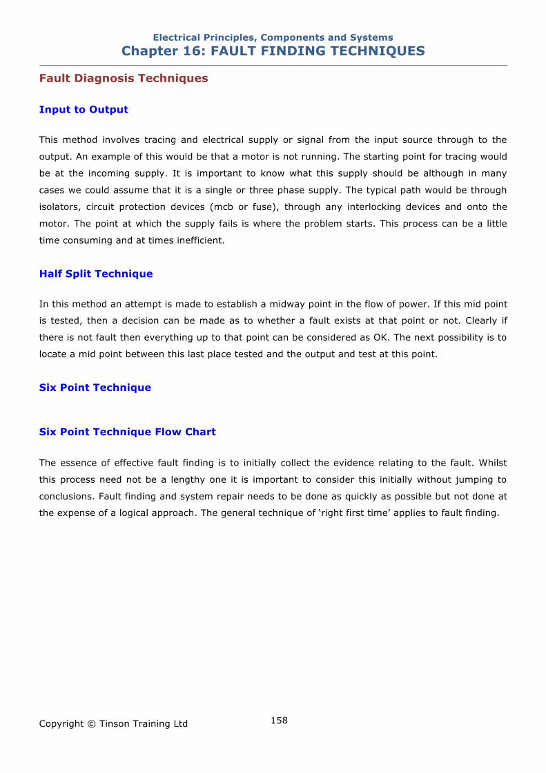
Electrical Principles, Components and Systems Chapter 16: FAULT FINDING TECHNIQUES
Copyright © Tinson Training Ltd
158
Fault Diagnosis Techniques Input to Output This method involves tracing and electrical supply or signal from the input source through to the
output. An example of this would be that a motor is not running. The starting point for tracing would
be at the incoming supply. It is important to know what this supply should be although in many
cases we could assume that it is a single or three phase supply. The typical path would be through
isolators, circuit protection devices (mcb or fuse), through any interlocking devices and onto the
motor. The point at which the supply fails is where the problem starts. This process can be a little
time consuming and at times inefficient.
Half Split Technique In this method an attempt is made to establish a midway point in the flow of power. If this mid point
is tested, then a decision can be made as to whether a fault exists at that point or not. Clearly if
there is not fault then everything up to that point can be considered as OK. The next possibility is to
locate a mid point between this last place tested and the output and test at this point.
Six Point Technique Six Point Technique Flow Chart
The essence of effective fault finding is to initially collect the evidence relating to the fault. Whilst
this process need not be a lengthy one it is important to consider this initially without jumping to
conclusions. Fault finding and system repair needs to be done as quickly as possible but not done at
the expense of a logical approach. The general technique of ‘right first time’ applies to fault finding.
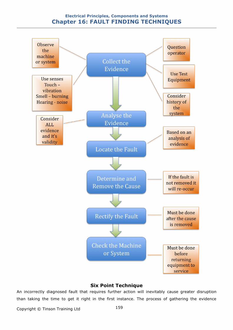
Electrical Principles, Components and Systems Chapter 16: FAULT FINDING TECHNIQUES
Copyright © Tinson Training Ltd
159
Six Point Technique An incorrectly diagnosed fault that requires further action will inevitably cause greater disruption
than taking the time to get it right in the first instance. The process of gathering the evidence
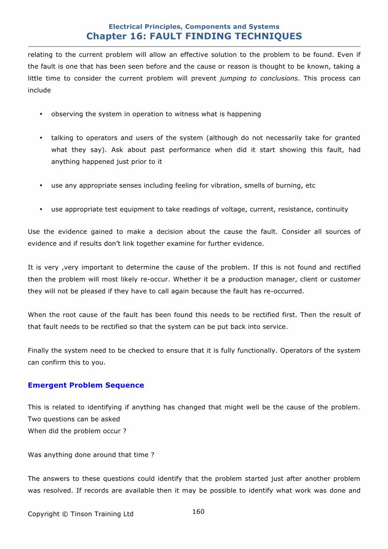
Electrical Principles, Components and Systems Chapter 16: FAULT FINDING TECHNIQUES
Copyright © Tinson Training Ltd
160
relating to the current problem will allow an effective solution to the problem to be found. Even if
the fault is one that has been seen before and the cause or reason is thought to be known, taking a
little time to consider the current problem will prevent jumping to conclusions. This process can
include
• observing the system in operation to witness what is happening
• talking to operators and users of the system (although do not necessarily take for granted
what they say). Ask about past performance when did it start showing this fault, had
anything happened just prior to it
• use any appropriate senses including feeling for vibration, smells of burning, etc
• use appropriate test equipment to take readings of voltage, current, resistance, continuity
Use the evidence gained to make a decision about the cause the fault. Consider all sources of
evidence and if results don’t link together examine for further evidence.
It is very ,very important to determine the cause of the problem. If this is not found and rectified
then the problem will most likely re-occur. Whether it be a production manager, client or customer
they will not be pleased if they have to call again because the fault has re-occurred.
When the root cause of the fault has been found this needs to be rectified first. Then the result of
that fault needs to be rectified so that the system can be put back into service.
Finally the system need to be checked to ensure that it is fully functionally. Operators of the system
can confirm this to you.
Emergent Problem Sequence
This is related to identifying if anything has changed that might well be the cause of the problem.
Two questions can be asked
When did the problem occur ?
Was anything done around that time ?
The answers to these questions could identify that the problem started just after another problem
was resolved. If records are available then it may be possible to identify what work was done and
Electrical Principles, Components and Systems Chapter 16: FAULT FINDING TECHNIQUES
Copyright © Tinson Training Ltd
161
maybe inspection of that work could reveal a problem. Such problems might be that an incorrect
part has been fitted or fitted incorrectly.
Typical Electrical Problems and their Remedies Volt Drops When current flows through a resistance there will be a voltage developed across that resistance.
That will result in a volt drop from the voltage prior to the resistance.
Volt Drops
Poor Connections The greater the resistance, the greater the volt drop. If there is no resistance there will no volt drop.
All conductors will have resistance and cables ideally will have zero resistance. Connections within a
supply line could be a source of resistance. Poor connections will definitely be a source of resistance.
A bad connection results in a reduction of cross sectional area of the conductor. A screw terminal
that is not fastened tightly will not make adequate contact with the conductor and reduce the area
of contact. The volt drop can be measured by measuring the voltage (with respect to the common
line 0V or ground) before the connection and after the connection. The reduced voltage will be
observed after the connection.
Remedy Improve the connection. This may be achieved by simple tightening the screw terminal. It may also
be necessary to remove the cable and inspect the stripped end. Ensure that the cable end is
stripped and that the exposed area of the conductor is good. If the cable is stranded ensure that
there are all the strands available. If the cable is solid ensure that the cable is good and not
damaged. In both cases, if necessary, cut off the poor end and re-strip the cable. Insert the stripped
end completely in to the terminal and tighten the screw securely. Afterwards re-measure the volt
drop. Ideally this should be zero.
Electrical Principles, Components and Systems Chapter 16: FAULT FINDING TECHNIQUES
Copyright © Tinson Training Ltd
162
High Current Higher than normal currents will give volt drops greater than expected. A high current will occur
when there is a fault in the equipment that is being supplied. Under these circumstances it would be
advisable to check the current being supplied to the equipment. If it is possible to determine the
normal current then this can be compared with the measured current. The remedy under these
circumstances is to replace the faulty equipment.
Loss of Supply Control equipment will have a main feed, which in many cases will be three phase. From this three
phase, other supplies will be obtained e.g. single phase at 230V or 110V or DC. In the event of the
loss of a supply it is necessary to know from where this supply is obtained. Typically it should be
feasible to work backwards from this supply towards the source eventually finding the point where
the supply fails.
Remedy
Supplies will be disconnected through isolators, circuit breakers, fuses and control equipment such
as contactors and relays.
Isolators Switched Off Locate the isolator and switch on
Circuit breakers and fuses These will have operated for a reason and it will be necessary to establish the reason. Replacing
fuses and resetting breakers may in some cases solve the problem but it must always be considered
“why did this protection device operate”.
There are three possible outcomes when replacing or resetting a protection device.
1. The device immediately trips again. The fault is permanently on the circuit and has to be
rectified. This can be achieved by isolating equipment to see if the fault disappears when a
device has been disconnected.
Check resistance of the line using a multimeter or insulation tester
Electrical Principles, Components and Systems Chapter 16: FAULT FINDING TECHNIQUES
Copyright © Tinson Training Ltd
163
2. The device holds but trips again some time later. The current could be greater than it’s
intended value and the circuit breaker or fuse is responding to this high level of current by
tripping out after the elapsed time according to the operating characteristics of the device.
Measuring the current with a clamp meter could help identify this situation. If the current is
not at a high value then the problem can be intermittent. Talk to operators to see if any
common patterns arise when the problem occurs. Make notes on the situation for others to
see should this problem keep occurring. Intermittent problems can take some time to resolve
and if other people (other shifts) may well be encountering this problem it is useful to work
from common information.
3. The device is reset and does not trip again. It is not necessary to be concerned about this
situation if it does not happen again.
Failed Sensors Sensors being electronic devices can fail periodically. It is likely that the tell tale indication will fail to
illuminate when the device fails. Testing of the device can be done by using a meter and checking
the signal lead. Invariably by checking between the signal wire and ground and looking for a change
of state when the sensor is activated. Typically the variation of signal level will be between the two
supply voltages. E.g. a sensor may in it’s inactivated state give out an output of say 24V and when
sensing it falls to 0V, or vice versa. It this test reveals no change of state then it might be necessary
to check any intermediate interconnections. In some instances the sensor may have a cable and
connector assembly which can be tested for continuity.
Failed Contactors / Relays Switching devices such as relays can fail with coil going open circuit. To check the relay operation it
may be necessary first to check the coil voltage. If the coil voltage is present but the relay is not
operating then it can be assumed that the contactor/relay has failed. Coils can be checked with a
meter set on resistance.
Failed Motors All Motors
Check Bearings
Check for windings smelling of burning.

Electrical Principles, Components and Systems Chapter 16: FAULT FINDING TECHNIQUES
Copyright © Tinson Training Ltd
164
Check winding continuity and impedance/resistance (balance if necessary)
Check insulation between windings and winding to earth/case.
DC Motors
Check for the following
General Visual Inspection
• Look for obvious signs of sparking, overheating or burning
• Examine the windings for local overheating
Run the machine and watch the commutator
Excessive sparking indicates many possible faults such as
• Wrong brush position or pressure
• Brushes spaced incorrectly around the commutator
• Brushes misaligned
• Interpole polarity incorrect
• Incorrect grade or type of brush
• Dirt under brushes or on segments
• Projecting commutator segments
• Commutator flats
• Out balance or eccentricity
• Unequal air gaps
Examine the surface of the commutator.
Blackened or burning may indicate faults such as
• Faulty commutation
• Oil on the segments
• Corrosive atmosphere
• Bad joints or open circuit armature coil
Examine the brush flexibles for signs of burning that may indicate
• Wrong distribution current
• Broken strands in the brush flexible
Electrical Principles, Components and Systems Chapter 16: FAULT FINDING TECHNIQUES
Copyright © Tinson Training Ltd
165
• Brushes sticking in their boxes
• Wrong spacing of brush box supports
• Mixed grade of brushes
• Corrosion, loose screws or leads too short
With the machine running, listen for chattering which may be caused by
• Projecting separators
• Flats on the commutator
• Unbalanced armature
• Commutator eccentric or oval
• Wrong grade or type of brush
AC Motors
• Examine carefully the end windings of all wound rotors and stators. On small machines the
wire may only be anchored by varnish or an adhesive. A loose wire may vibrate and lead to a
breakdown.
• Ensure that all wires are adequately secured. On large machines, elaborate supporting
arrangements are made.
• Check the security of packing blocks, wedges and other components
• Look for damage or deterioration of insulation, especially at the end slots
• Look for obvious signs of overheating and arcing e.g. discoloration and melted metal.
• Examine joints carefully looking for cracks. It may be possible to feel the movement at the
joint.
Failed Solenoids Solenoids will fail when the coil goes open circuit. If the control voltage is present but the solenoid
does not operate it can be assumed faulty. A continuity test can be performed on the coil. This
should normally read low resistance.
Electrical Principles, Components and Systems Chapter 16: FAULT FINDING TECHNIQUES
Copyright © Tinson Training Ltd
166
Electrical Principles, Components and Systems Chapter 16: FAULT FINDING TECHNIQUES
Copyright © Tinson Training Ltd
167
ON LINE EXERCISE
Click here to access Chapter 16: Fault Finding Techniques - On Line Exercises
Electrical Principles, Components and Systems APPENDIX A
Copyright © Tinson Training Ltd
168
Appendix A
Electricity at Work Regulations 1989
The Electricity at Work Regulations 1989 were made under the Health and Safety at Work Act 1974
and reinforce the requirements of the HASAWA with respect to the use of electricity.
The 1989 regulations apply to employers, the self employed and employees, all of whom will be
responsible where matters are within their control.
A summary of the responsibilities called for under the 1989 regulations are given against the
relevant regulation number.
4(1) to ensure at all times that the electrical system is of such construction as to make it safe
4(2) the electrical system is maintained so that it remains safe
4(3) that no person is in danger whilst using, operating, maintaining, or working near such a
system
4(4) that any equipment provided for the purpose of protecting persons at work, on or near
electrical equipment, shall be suitable for that purpose, shall be maintained and shall be
properly used
5 that the system has sufficient strength and capability for any short circuit currents,
overload currents and voltage surges etc. That can foreseeable occur
6 the equipment is suitable for any environmental conditions to which it may be reasonably
and foreseeable be exposed
Electrical Principles, Components and Systems APPENDIX A
Copyright © Tinson Training Ltd
169
7 all conductors that can give rise to a danger to be insulated, protected or suitable placed so
as not to cause a danger
8 precautions to be taken either by earthing or other suitable means to prevent a danger
when any conductor (other than a circuit conductor) becomes charged (has a voltage on
it); the earthing conductor being capable of carrying any fault current without danger
10 that every joint and connection in a system is mechanically and electrically suitable so as
not to prevent a danger
11 that where necessary protection is provided to disconnect any excess current before danger
can occur
12 that provision is made for cutting off the supply or isolating equipment as may be
necessary to prevent danger
13 when equipment and conductors are made dead, suitable precautions must be taken to
ensure that do not become electrically charged
14 that no person shall be allowed to work on or near any live conductor where a danger
could arise unless:
a) it is unreasonable in all circumstances for the equipment or conductor to be
dead and
b) it is reasonable in all circumstances for that person to be at work on or near it while it
is live
15 that there is adequate working space, access and lighting for working on or near an
electrical system
16 that no person is engaged in any work or activity unless they are competent for the duties
they have to perform
Electrical Principles, Components and Systems APPENDIX B
Copyright © Tinson Training Ltd
170
Appendix B
The IEE Wiring Regulations (BS 7671 – 2008)
The IEE Wiring Regulations is the British standard that covers the safe design, installation and
testing of electrical installations in building systems. In addition the regulations define special
locations as
• Bathrooms
• Swimming Pools
• Hot Air Saunas
• Construction Sites
• Horticultural and Agricultural Locations
• Restrictive Conductive Locations
• Caravan and Camping Parks
• Marinas
• Exhibition shows and stands
• Solar Photo Voltaic Supply Systems
• Mobile and Transportable Units
• Caravans and Motor Caravans
• Amusement Devices, Fairgrounds and Circuses
Electrical Principles, Components and Systems APPENDIX B
Copyright © Tinson Training Ltd
171
• Floor and Ceiling Heating Systems
In the most simple form the wiring regulations are concerned with the following
• Use of good workmanship.
• Use of approved equipment and materials.
• Ensure that the correct type, size and current carrying capacity of cables are used.
• Ensure equipment is suitable for the maximum power demanded of it.
• Make sure conductors are insulated and sheathed or protected if necessary, or are placed in
a position to prevent danger.
• Joints and connections should be properly constructed to be mechanically and electrically
sound
• Always provide over current protection for every circuit in an electrical installation and ensure
that protective devices are suitably chosen for their location and duty that they have to
perform.
• Where there is a chance of metalwork becoming live owing to a fault, it should be earthed
and the circuit concerned should be protected by an over current device or a Residual
Current Device.
• Ensure that all necessary bonding of services is carried out.
• Do not place a fuse, or a switch or a circuit breaker unless it is a linked switch or circuit
breaker in an earthed neutral conductor. The linked type must break all line conductors.
• All single pole switches must be wired in the line conductor only.
• A readily accessible means of isolation must be provided so that all voltages may be cut off
from an installation or any of it’s circuits.
• All motors must have a readily accessible means of disconnection.
Electrical Principles, Components and Systems APPENDIX B
Copyright © Tinson Training Ltd
172
• Ensure that any item of equipment which may normally need operating or attending by
persons is accessible and easily operated.
• Any equipment required to be installed in a situation exposed to weather or corrosion, or in
explosive or volatile environments, should be of the correct type for such adverse conditions.
• Before adding to or altering an installation ensure that such work will not impair any part of
the existing installation and that the existing installation is in a safe position to accommodate
the addition.
• After completion of an installation or alteration to an installation, the work must be inspected
and tested, so far as reasonably practical, that the fundamental requirements for safety have
been met.
It is worth noting that although the wiring regulations are not statutory they may be used to claim
compliance with statutory regulations such as the Electricity at Work Regulations, Health and Safety
at Work Act and Part P of the building regulations.
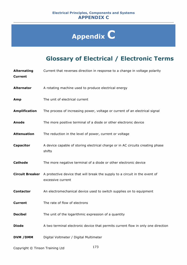
Electrical Principles, Components and Systems APPENDIX C
Copyright © Tinson Training Ltd
173
Appendix C
Glossary of Electrical / Electronic Terms
Alternating
Current
Current that reverses direction in response to a change in voltage polarity
Alternator A rotating machine used to produce electrical energy
Amp
The unit of electrical current
Amplification The process of increasing power, voltage or current of an electrical signal
Anode The more positive terminal of a diode or other electronic device
Attenuation The reduction in the level of power, current or voltage
Capacitor A device capable of storing electrical charge or in AC circuits creating phase
shifts
Cathode The more negative terminal of a diode or other electronic device
Circuit Breaker A protective device that will break the supply to a circuit in the event of
excessive current
Contactor An electromechanical device used to switch supplies on to equipment
Current The rate of flow of electrons
Decibel The unit of the logarithmic expression of a quantity
Diode A two terminal electronic device that permits current flow in only one direction
DVM /DMM Digital Voltmeter / Digital Multimeter
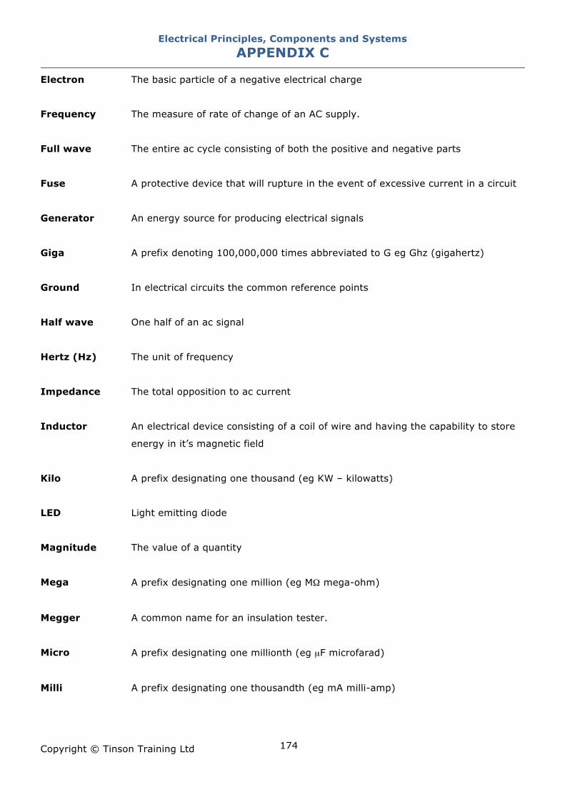
Electrical Principles, Components and Systems APPENDIX C
Copyright © Tinson Training Ltd
174
Electron The basic particle of a negative electrical charge
Frequency The measure of rate of change of an AC supply.
Full wave The entire ac cycle consisting of both the positive and negative parts
Fuse A protective device that will rupture in the event of excessive current in a circuit
Generator An energy source for producing electrical signals
Giga A prefix denoting 100,000,000 times abbreviated to G eg Ghz (gigahertz)
Ground In electrical circuits the common reference points
Half wave One half of an ac signal
Hertz (Hz) The unit of frequency
Impedance The total opposition to ac current
Inductor An electrical device consisting of a coil of wire and having the capability to store
energy in it’s magnetic field
Kilo A prefix designating one thousand (eg KW – kilowatts)
LED Light emitting diode
Magnitude The value of a quantity
Mega A prefix designating one million (eg M! mega-ohm)
Megger A common name for an insulation tester.
Micro A prefix designating one millionth (eg µF microfarad)
Milli A prefix designating one thousandth (eg mA milli-amp)
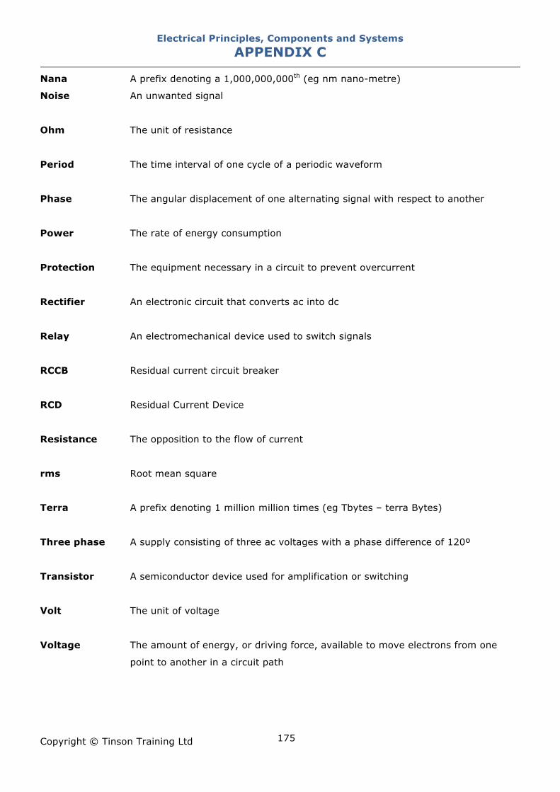
Electrical Principles, Components and Systems APPENDIX C
Copyright © Tinson Training Ltd
175
Nana A prefix denoting a 1,000,000,000th (eg nm nano-metre)
Noise An unwanted signal
Ohm The unit of resistance
Period The time interval of one cycle of a periodic waveform
Phase The angular displacement of one alternating signal with respect to another
Power The rate of energy consumption
Protection The equipment necessary in a circuit to prevent overcurrent
Rectifier An electronic circuit that converts ac into dc
Relay An electromechanical device used to switch signals
RCCB Residual current circuit breaker
RCD Residual Current Device
Resistance The opposition to the flow of current
rms Root mean square
Terra A prefix denoting 1 million million times (eg Tbytes – terra Bytes)
Three phase A supply consisting of three ac voltages with a phase difference of 120º
Transistor A semiconductor device used for amplification or switching
Volt The unit of voltage
Voltage The amount of energy, or driving force, available to move electrons from one
point to another in a circuit path
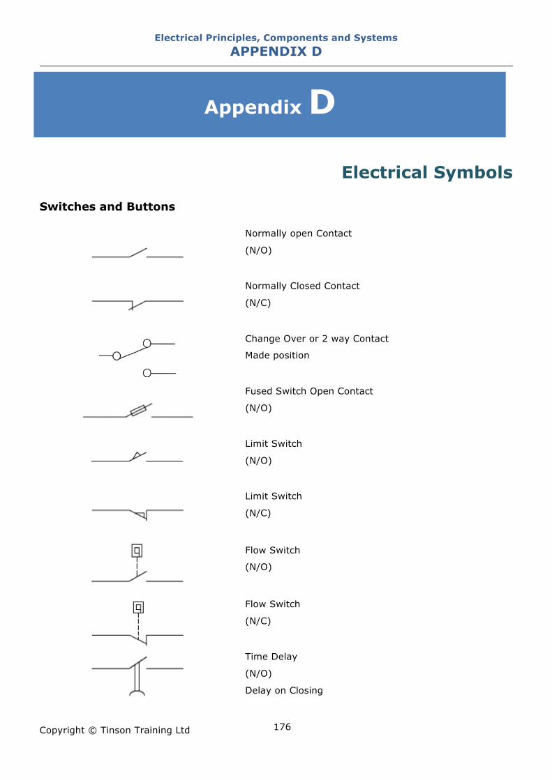
Electrical Principles, Components and Systems APPENDIX D
Copyright © Tinson Training Ltd
176
Appendix D
Electrical Symbols
Switches and Buttons
Normally open Contact
(N/O)
Normally Closed Contact
(N/C)
Change Over or 2 way Contact
Made position
Fused Switch Open Contact
(N/O)
Limit Switch
(N/O)
Limit Switch
(N/C)
Flow Switch
(N/O)
Flow Switch
(N/C)
Time Delay
(N/O)
Delay on Closing
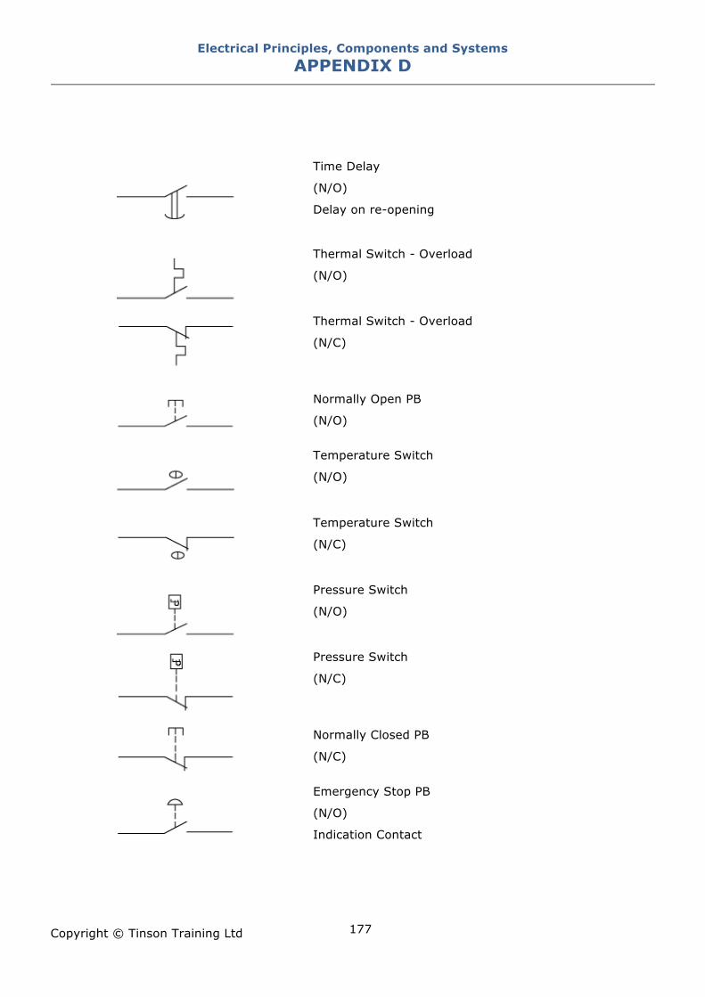
Electrical Principles, Components and Systems APPENDIX D
Copyright © Tinson Training Ltd
177
Time Delay
(N/O)
Delay on re-opening
Thermal Switch - Overload
(N/O)
Thermal Switch - Overload
(N/C)
Normally Open PB
(N/O)
Temperature Switch
(N/O)
Temperature Switch
(N/C)
Pressure Switch
(N/O)
Pressure Switch
(N/C)
Normally Closed PB
(N/C)
Emergency Stop PB
(N/O)
Indication Contact
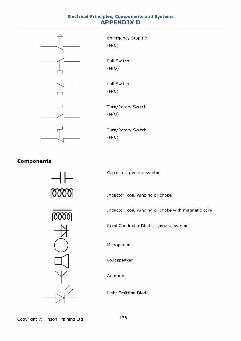
Electrical Principles, Components and Systems APPENDIX D
Copyright © Tinson Training Ltd
178
Emergency Stop PB
(N/C)
Pull Switch
(N/O)
Pull Switch
(N/C)
Turn/Rotary Switch
(N/O)
Turn/Rotary Switch
(N/C)
Components
Capacitor, general symbol
Inductor, coil, winding or choke
Inductor, coil, winding or choke with magnetic core
Semi Conductor Diode - general symbol
Microphone
Loudspeaker
Antenna
Light Emitting Diode
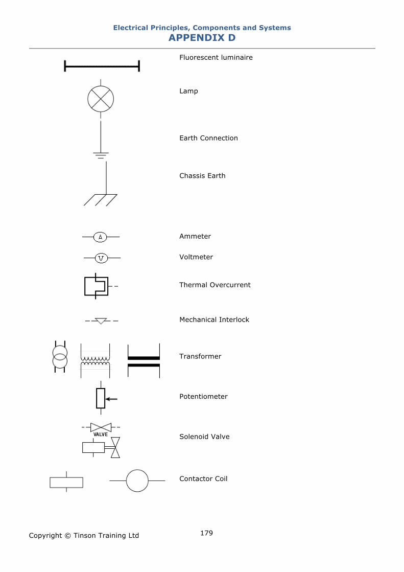
Electrical Principles, Components and Systems APPENDIX D
Copyright © Tinson Training Ltd
179
Fluorescent luminaire
Lamp
Earth Connection
Chassis Earth
Ammeter
Voltmeter
Thermal Overcurrent
Mechanical Interlock
Transformer
Potentiometer
Solenoid Valve
Contactor Coil
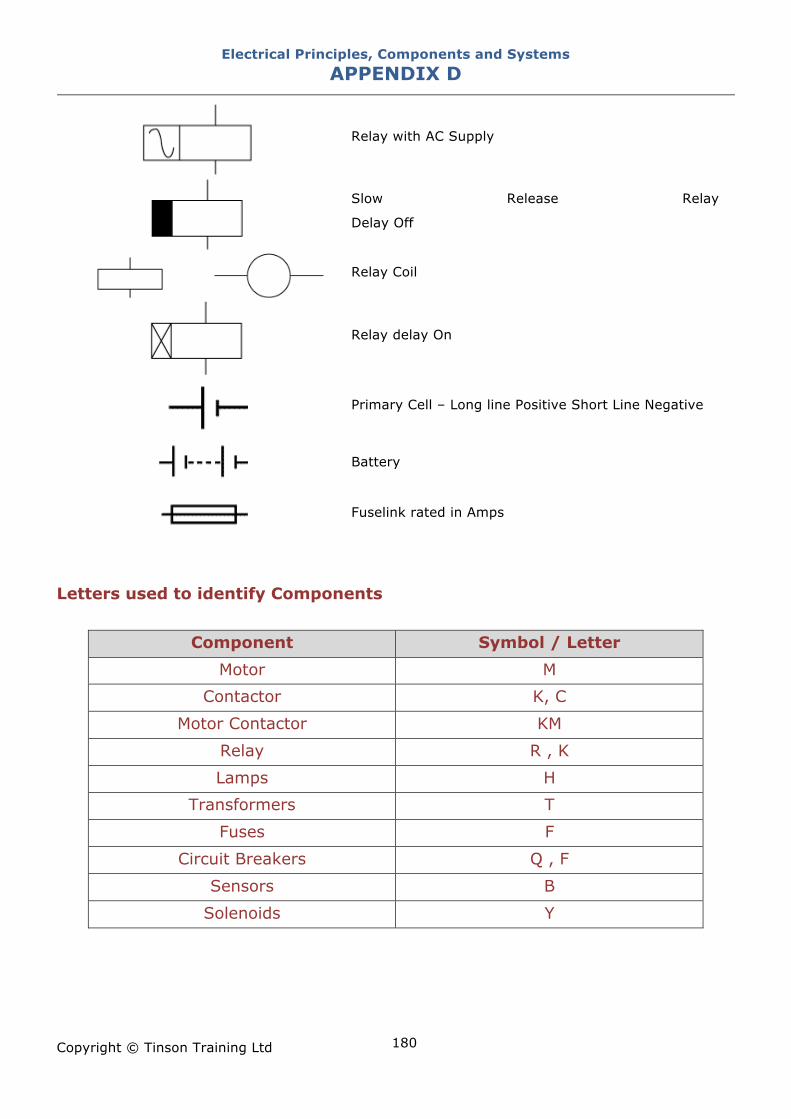
Electrical Principles, Components and Systems APPENDIX D
Copyright © Tinson Training Ltd
180
Relay with AC Supply
Slow Release Relay
Delay Off
Relay Coil
Relay delay On
Primary Cell – Long line Positive Short Line Negative
Battery
Fuselink rated in Amps
Letters used to identify Components
Component Symbol / Letter
Motor M
Contactor K, C
Motor Contactor KM
Relay R , K
Lamps H
Transformers T
Fuses F
Circuit Breakers Q , F
Sensors B
Solenoids Y
Electrical Principles, Components and Systems APPENDIX E
Copyright © Tinson Training Ltd
181
Appendix E
Index of Protection (Ingress Protection) IP
Rating EN 60529 outlines an international classification system for the sealing effectiveness of enclosures of
electrical equipment against the intrusion into the equipment of foreign bodies (i.e. tools, dust,
fingers) and moisture. This classification system utilizes the letters "IP" ("Ingress Protection" or
“Index of Protection” ) followed by two or three digits. (A third digit is optional. An "x" is used for
one of the digits if there is only one class of protection; i.e. IPX4 which addresses moisture
resistance only.)
The standard aims to provide users more detailed information than vague marketing terms such as
"waterproof".
For example, an electrical socket rated IP22 is protected against insertion of fingers and will not be
damaged or become unsafe during a specified test in which it is exposed to vertically or nearly
vertically dripping water. IP22 or IP2X are typical minimum requirements for the design of electrical
accessories for indoor use.
Degrees of Protection - First Digit
The first digit of the IP code indicates the degree that persons are protected against contact with
moving parts (other than smooth rotating shafts, etc.) and the degree that equipment is protected
against solid foreign bodies intruding into an enclosure.
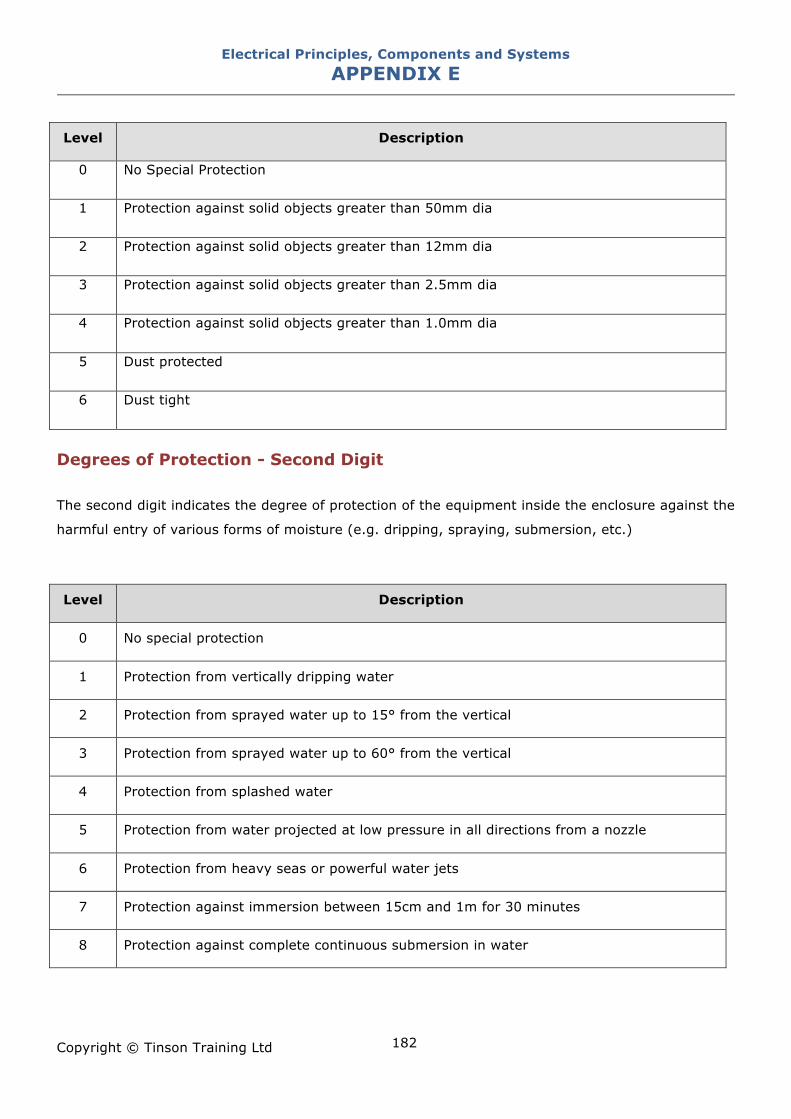
Electrical Principles, Components and Systems APPENDIX E
Copyright © Tinson Training Ltd
182
Level Description
0 No Special Protection
1 Protection against solid objects greater than 50mm dia
2 Protection against solid objects greater than 12mm dia
3 Protection against solid objects greater than 2.5mm dia
4 Protection against solid objects greater than 1.0mm dia
5 Dust protected
6 Dust tight
Degrees of Protection - Second Digit
The second digit indicates the degree of protection of the equipment inside the enclosure against the
harmful entry of various forms of moisture (e.g. dripping, spraying, submersion, etc.)
Level Description
0 No special protection
1 Protection from vertically dripping water
2 Protection from sprayed water up to 15° from the vertical
3 Protection from sprayed water up to 60° from the vertical
4 Protection from splashed water
5 Protection from water projected at low pressure in all directions from a nozzle
6 Protection from heavy seas or powerful water jets
7 Protection against immersion between 15cm and 1m for 30 minutes
8 Protection against complete continuous submersion in water
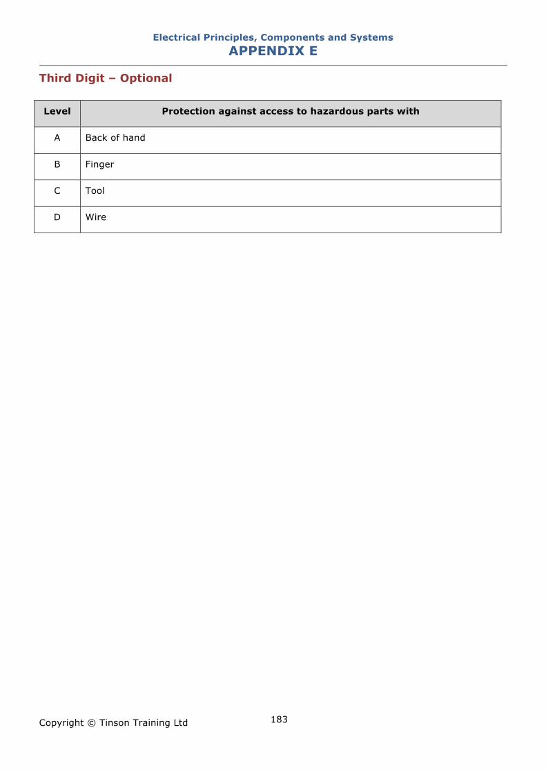
Electrical Principles, Components and Systems APPENDIX E
Copyright © Tinson Training Ltd
183
Third Digit – Optional Level Protection against access to hazardous parts with
A Back of hand
B Finger
C Tool
D Wire
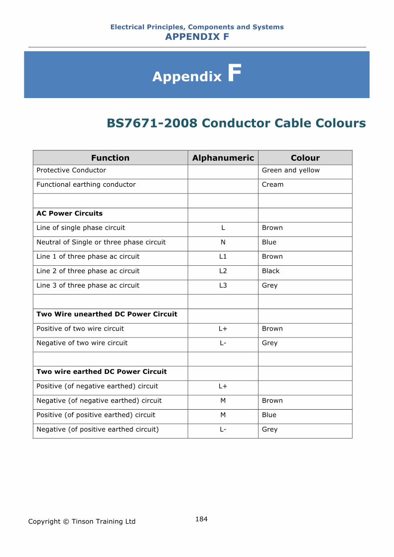
Electrical Principles, Components and Systems APPENDIX F
Copyright © Tinson Training Ltd
184
Appendix F
BS7671-2008 Conductor Cable Colours
Function Alphanumeric Colour
Protective Conductor Green and yellow
Functional earthing conductor Cream
AC Power Circuits
Line of single phase circuit L Brown
Neutral of Single or three phase circuit N Blue
Line 1 of three phase ac circuit L1 Brown
Line 2 of three phase ac circuit L2 Black
Line 3 of three phase ac circuit L3 Grey
Two Wire unearthed DC Power Circuit
Positive of two wire circuit L+ Brown
Negative of two wire circuit L- Grey
Two wire earthed DC Power Circuit
Positive (of negative earthed) circuit L+
Negative (of negative earthed) circuit M Brown
Positive (of positive earthed) circuit M Blue
Negative (of positive earthed circuit) L- Grey
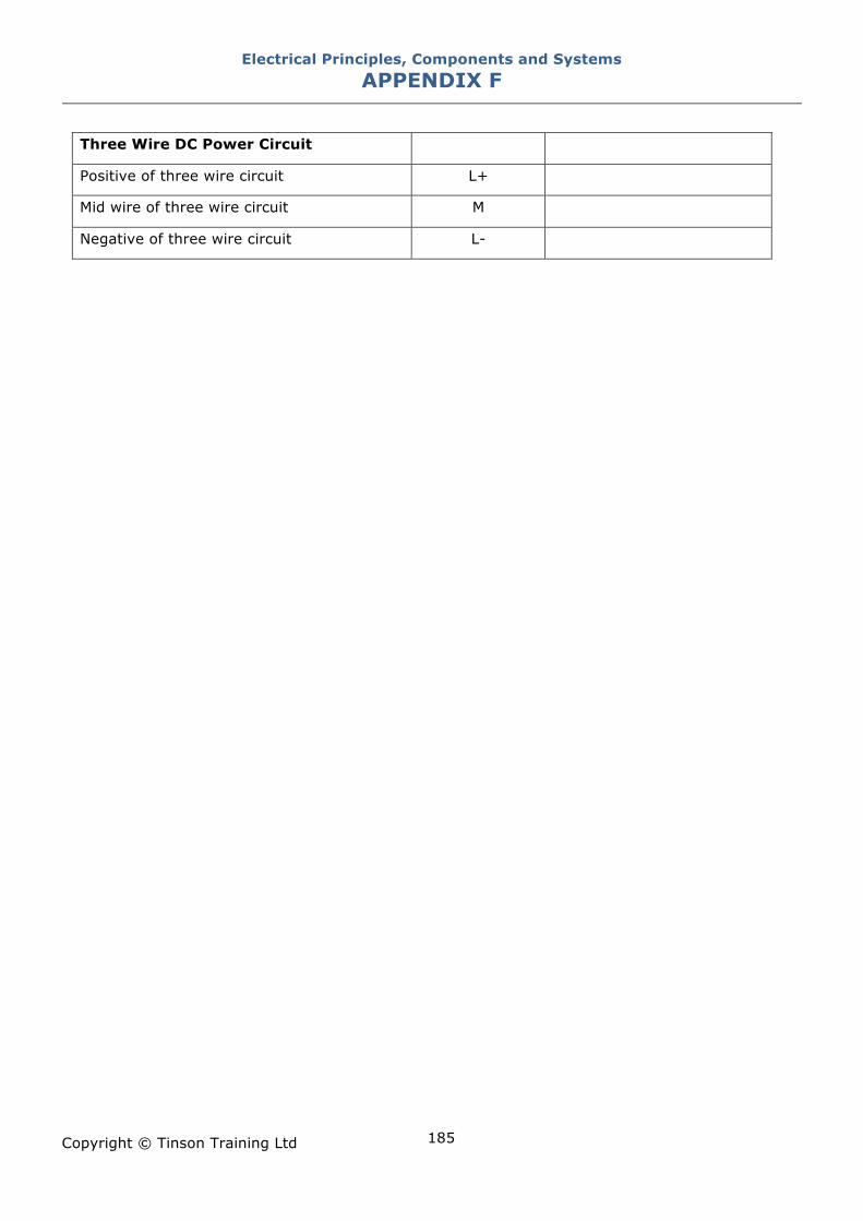
Electrical Principles, Components and Systems APPENDIX F
Copyright © Tinson Training Ltd
185
Three Wire DC Power Circuit Positive of three wire circuit L+ Mid wire of three wire circuit M Negative of three wire circuit L-
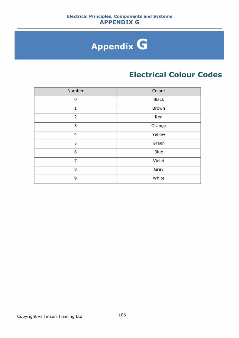
Electrical Principles, Components and Systems APPENDIX G
Copyright © Tinson Training Ltd
186
Appendix G
Electrical Colour Codes
Number Colour
0 Black
1 Brown
2 Red
3 Orange
4 Yellow
5 Green
6 Blue
7 Violet
8 Grey
9 White
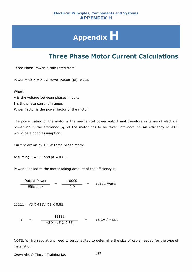
Electrical Principles, Components and Systems APPENDIX H
Copyright © Tinson Training Ltd
187
Appendix H
Three Phase Motor Current Calculations Three Phase Power is calculated from
Power = "3 X V X I X Power Factor (pf) watts
Where
V is the voltage between phases in volts
I is the phase current in amps
Power Factor is the power factor of the motor
The power rating of the motor is the mechanical power output and therefore in terms of electrical
power input, the efficiency (#) of the motor has to be taken into account. An efficiency of 90%
would be a good assumption.
Current drawn by 10KW three phase motor
Assuming # = 0.9 and pf = 0.85
Power supplied to the motor taking account of the efficiency is
Output Power 10000
Efficiency =
0.9 = 11111 Watts
11111 = "3 X 415V X I X 0.85
11111 I =
"3 X 415 X 0.85 = 18.2A / Phase
NOTE: Wiring regulations need to be consulted to determine the size of cable needed for the type of
installation.
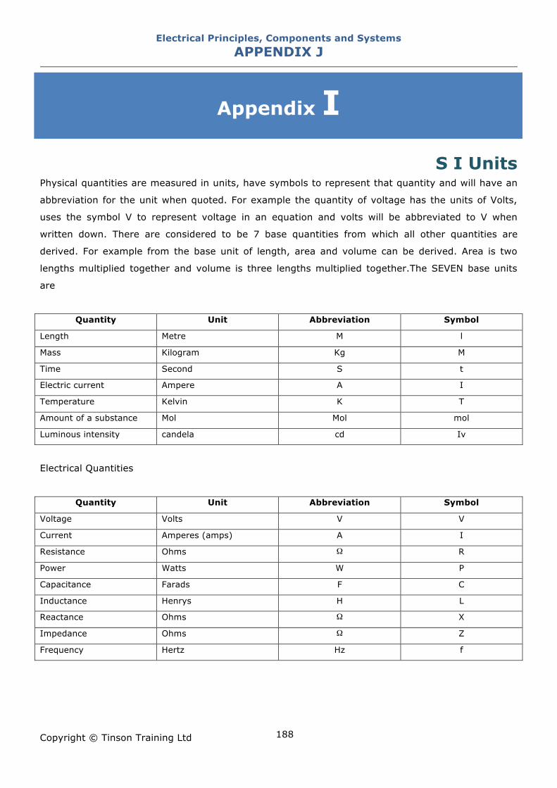
Electrical Principles, Components and Systems APPENDIX J
Copyright © Tinson Training Ltd
188
Appendix I
S I Units Physical quantities are measured in units, have symbols to represent that quantity and will have an
abbreviation for the unit when quoted. For example the quantity of voltage has the units of Volts,
uses the symbol V to represent voltage in an equation and volts will be abbreviated to V when
written down. There are considered to be 7 base quantities from which all other quantities are
derived. For example from the base unit of length, area and volume can be derived. Area is two
lengths multiplied together and volume is three lengths multiplied together.The SEVEN base units
are
Quantity Unit Abbreviation Symbol
Length Metre M l
Mass Kilogram Kg M
Time Second S t
Electric current Ampere A I
Temperature Kelvin K T
Amount of a substance Mol Mol mol
Luminous intensity candela cd Iv
Electrical Quantities
Quantity Unit Abbreviation Symbol
Voltage Volts V V
Current Amperes (amps) A I
Resistance Ohms ! R
Power Watts W P
Capacitance Farads F C
Inductance Henrys H L
Reactance Ohms ! X
Impedance Ohms ! Z
Frequency Hertz Hz f