electromagnetic clutch-brake combinations intorq 14.800–14 · electromagnetic clutch-brake...
TRANSCRIPT
Electromagnetic clutch-brake combinationsINTORQ 14.800 – 14.867
setting the standard
7.5 – 120 Nm

4 ❚ CBC en 5/2005
Clutch-brake combinations
Electromagnetic clutch-brake combinations have been
enjoying market success for a number of years. They are
used in all areas of mechanical engineering when a
production sequence has to be synchronised. As the drive
runs continuously with the clutch rotor, the energy from
the upstream drive can be used to accelerate the output.
INTORQ 14.105/115 series electromagnetic clutches
and brakes are used in these clutch-brake combinations.
They are switched alternately in order to accelerate or
decelerate the output shaft. Torque transmission is
achieved using friction.
As well as the basic versions with free drive and output
shafts and hollow shafts, clutch-brake combinations are
also available with built-on three-phase AC motors and with
helical or worm gearboxes mounted at the output end. The
drives can be used in either a horizontal or vertical
mounting position. Using preassembled units significantly
reduces design costs for new developments and the time
spent on mounting.
Friction clutches and brakes are subject to a certain
amount of wear which is dependent on the switching
energy used. Automatic adjusting devices (which are
susceptible to faults) are no longer required, thanks to the
wear resistant, asbestos-free friction linings used.
Air gap compensation can be carried out quickly and
without disassembling the clutch-brake combination thanks
to patented wear adjustment.
The low moments of inertia of the wear-resistant armature
elements permit high switching frequencies and good
positioning accuracy which can be increased still further if
required, using the high-speed switchgear that is available.
Features❚ Five frame sizes from 7.5 to 120 Nm
❚ Asbestos-free friction linings
❚ Patented air gap adjustment can be performed externally
without disassembling the combination
❚ Operating times of the clutch and the brake do not
overlap
❚ A backlash-free version can be supplied on request
❚ Two shaft and two hollow shaft diameters as well as two
flange diameters in IEC dimensions are available for each
frame size
❚ Two axis heights are available for each frame size
❚ Insulation class B
❚ Dimensioned for 100% duty
❚ IP 44 enclosure, higher degrees of protection on request
❚ Rated voltage 24 V DC, other voltages on request
❚ Variable terminal box position; standard position is on
left when looking at the drive end
❚ VDE (Association of German Electrotechnical Engineers)
0580
Brake stator
Armature plate Rotor
Clutch stator
DriveOutput
sair
Product information
CBC en 5/2005 ❚ 5
Clutch-brake combinations
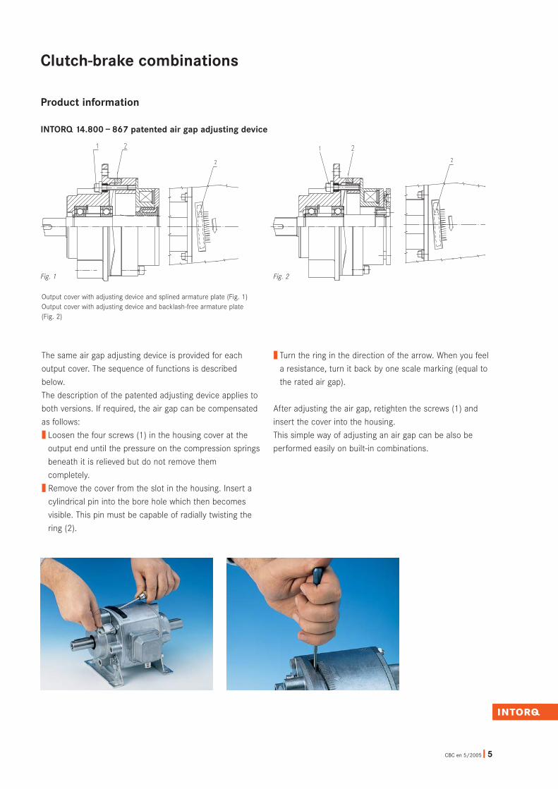
The same air gap adjusting device is provided for each
output cover. The sequence of functions is described
below.
The description of the patented adjusting device applies to
both versions. If required, the air gap can be compensated
as follows:
❚ Loosen the four screws (1) in the housing cover at the
output end until the pressure on the compression springs
beneath it is relieved but do not remove them
completely.
❚ Remove the cover from the slot in the housing. Insert a
cylindrical pin into the bore hole which then becomes
visible. This pin must be capable of radially twisting the
ring (2).
❚ Turn the ring in the direction of the arrow. When you feel
a resistance, turn it back by one scale marking (equal to
the rated air gap).
After adjusting the air gap, retighten the screws (1) and
insert the cover into the housing.
This simple way of adjusting an air gap can be also be
performed easily on built-in combinations.
Output cover with adjusting device and splined armature plate (Fig. 1)Output cover with adjusting device and backlash-free armature plate (Fig. 2)
Fig. 1 Fig. 2
Product information
INTORQ 14.800 – 867 patented air gap adjusting device

INTORQ 14.800. 06. 10. 1
Type
Frame size
Output-end version
Drive-end version
Variants
6 ❚ CBC en 5/2005
Clutch-brake combinations
TypeINTORQ 14.800 – clutch-brake combinations
without motor
INTORQ 14.810 – clutch-brake combinations
with motor
Output-end version10 – free output shaft, without foot, without flange
11 – free output shaft, with foot, without flange
12 – free output shaft, without foot, with flange
13 – free output shaft, with foot, with flange
20 – with hollow shaft, without foot, without flange
21 – with hollow shaft, without foot, with flange
22 – with hollow shaft, with foot, without flange
23 – with hollow shaft, with foot, with flange
Drive-end version1 – splined armature plate, free drive shaft
2 – splined armature plate, free drive shaft and flange
3 – splined armature plate, hollow shaft, B5 flange
4 – splined armature plate, hollow shaft, B14 flange
6 – backlash-free diaphragm armature plate,
free drive shaft
7 – backlash-free diaphragm armature plate,
free drive shaft and flange
8 – backlash-free diaphragm armature plate,
hollow shaft, B5 flange
9 – backlash-free diaphragm armature plate,
hollow shaft, B14 flange
VariantsClutch/brake voltage
Shaft diameter/bore diameter/flange diameter/foot
height/terminal box position
Motor:
Power – voltage
Speed – frequency
Degree of protection
For available motor frame sizes, see page 11.
Type codeINTORQ 14.800 – 14.810
8 ❚ CBC en 5/2005
Clutch-brake combinations
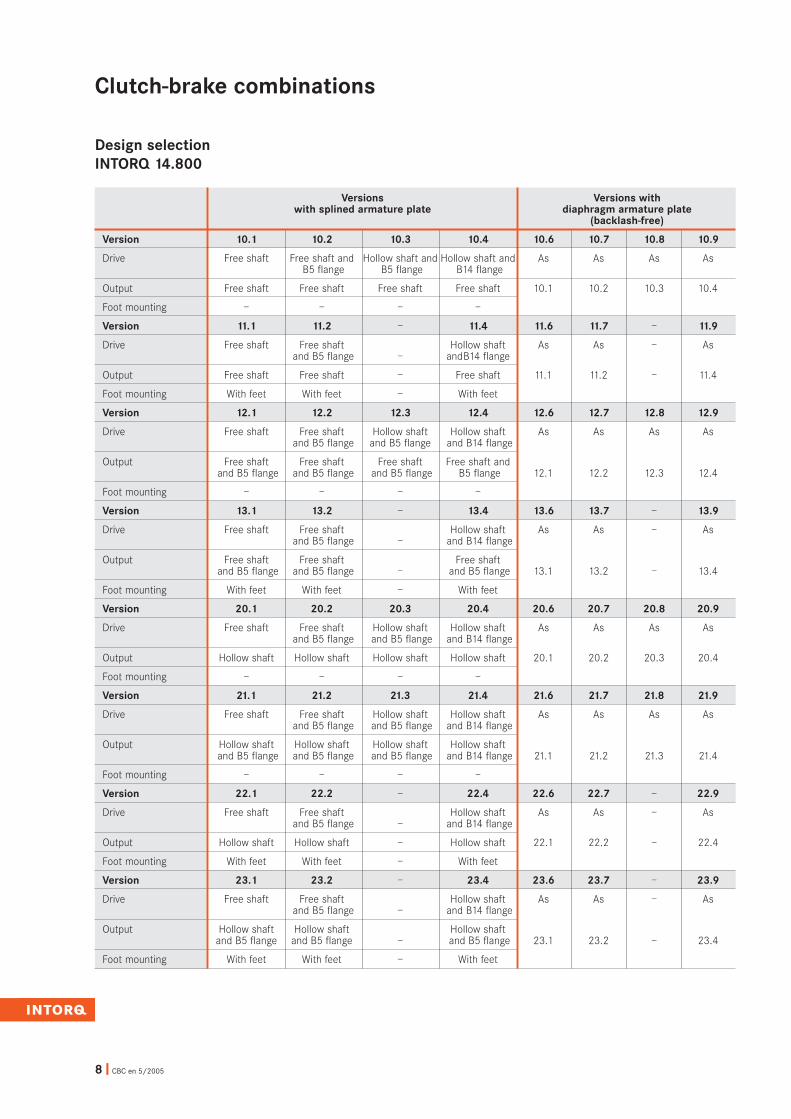
Design selectionINTORQ 14.800
Versions Versions withwith splined armature plate diaphragm armature plate
(backlash-free)
Version 10.1 10.2 10.3 10.4 10.6 10.7 10.8 10.9
Drive Free shaft Free shaft and Hollow shaft and Hollow shaft and As As As AsB5 flange B5 flange B14 flange
Output Free shaft Free shaft Free shaft Free shaft 10.1 10.2 10.3 10.4
Foot mounting – – – –
Version 11.1 11.2 – 11.4 11.6 11.7 – 11.9
Drive Free shaft Free shaft Hollow shaft As As – Asand B5 flange – and B14 flange
Output Free shaft Free shaft – Free shaft 11.1 11.2 – 11.4
Foot mounting With feet With feet – With feet
Version 12.1 12.2 12.3 12.4 12.6 12.7 12.8 12.9
Drive Free shaft Free shaft Hollow shaft Hollow shaft As As As Asand B5 flange and B5 flange and B14 flange
Output Free shaft Free shaft Free shaft Free shaft andand B5 flange and B5 flange and B5 flange B5 flange 12.1 12.2 12.3 12.4
Foot mounting – – – –
Version 13.1 13.2 – 13.4 13.6 13.7 – 13.9
Drive Free shaft Free shaft Hollow shaft As As – Asand B5 flange – and B14 flange
Output Free shaft Free shaft Free shaftand B5 flange and B5 flange – and B5 flange 13.1 13.2 – 13.4
Foot mounting With feet With feet – With feet
Version 20.1 20.2 20.3 20.4 20.6 20.7 20.8 20.9
Drive Free shaft Free shaft Hollow shaft Hollow shaft As As As Asand B5 flange and B5 flange and B14 flange
Output Hollow shaft Hollow shaft Hollow shaft Hollow shaft 20.1 20.2 20.3 20.4
Foot mounting – – – –
Version 21.1 21.2 21.3 21.4 21.6 21.7 21.8 21.9
Drive Free shaft Free shaft Hollow shaft Hollow shaft As As As Asand B5 flange and B5 flange and B14 flange
Output Hollow shaft Hollow shaft Hollow shaft Hollow shaftand B5 flange and B5 flange and B5 flange and B14 flange 21.1 21.2 21.3 21.4
Foot mounting – – – –
Version 22.1 22.2 – 22.4 22.6 22.7 – 22.9
Drive Free shaft Free shaft Hollow shaft As As – Asand B5 flange – and B14 flange
Output Hollow shaft Hollow shaft – Hollow shaft 22.1 22.2 – 22.4
Foot mounting With feet With feet – With feet
Version 23.1 23.2 – 23.4 23.6 23.7 – 23.9
Drive Free shaft Free shaft Hollow shaft As As – Asand B5 flange – and B14 flange
Output Hollow shaft Hollow shaft Hollow shaftand B5 flange and B5 flange – and B5 flange 23.1 23.2 – 23.4
Foot mounting With feet With feet – With feet

CBC en 5/2005 ❚ 9
Clutch-brake combinations
Output Drive
INTORQ 14.800.òò.10.1(6) Page 18
Output Drive
INTORQ 14.800.òò.10.4(9) Page 22
Output Drive
INTORQ 14.800.òò.11.4(9) Page 22
Output Drive
INTORQ 14.800.òò.12.3(8) Page 20
Output Drive
INTORQ 14.800.òò.13.2(7) Page 18
Output Drive
INTORQ 14.800.òò.20.2(7) Page 24
Output Drive
INTORQ 14.800.òò.10.2(7) Page 18
Output Drive
INTORQ 14.800.òò.11.1(6) Page 18
Output Drive
INTORQ 14.800.òò.12.1(6) Page 18
Output Drive
INTORQ 14.800.òò.12.4(9) Page 22
Output Drive
INTORQ 14.800.òò.13.4(9) Page 22
Output Drive
INTORQ 14.800.òò.20.3(8) Page 26
Output Drive
INTORQ 14.800.òò.10.3(8) Page 20
Output Drive
INTORQ 14.800.òò.11.2(7) Page 18
Output Drive
INTORQ 14.800.òò.12.2(7) Page 18
Output Drive
INTORQ 14.800.òò.13.1(6) Page 18
Output Drive
INTORQ 14.800.òò.20.1(6) Page 24
Output Drive
INTORQ 14.800.òò.20.4(9) Page 28
◊ ◊ ◊ ◊
◊ ◊
◊ ◊
◊ ◊
◊ ◊
◊ ◊
◊
◊
◊
◊
◊
◊
◊
◊
◊
◊
◊ ◊
◊ ◊
◊ ◊
◊ ◊
◊ ◊
◊ ◊
Overview of types

10 ❚ CBC en 5/2005
◊ ◊ ◊ ◊
◊ ◊
◊ ◊
◊ ◊
◊ ◊
◊
◊
◊
◊
◊
◊
◊◊
◊
◊
◊ ◊
◊ ◊
◊ ◊
◊ ◊
◊ ◊
Output Drive
INTORQ 14.800.òò.21.1(6) Page 24
Output Drive
INTORQ 14.800.òò.21.2(7) Page 24
Output Drive
INTORQ 14.800.òò.21.3(8) Page 26
Output Drive
INTORQ 14.800.òò.21.4(9) Page 28
Output Drive
INTORQ 14.800.òò.22.1(6) Page 24
Output Drive
INTORQ 14.800.òò.22.2(7) Page 24
Output Drive
INTORQ 14.800.òò.22.4(9) Page 28
Output Drive
INTORQ 14.800.òò.23.1(6) Page 24
Output Drive
INTORQ 14.800.òò.23.2(7) Page 24
Output Drive
INTORQ 14.800.òò.23.4(9) Page 28
Output Drive
INTORQ 14.810.òò.10.3(8) Page 20
Output Drive
INTORQ 14.810.òò.10.4(9) Page 22
Output Drive
INTORQ 14.810.òò.11.4(9) Page 22
Output Drive
INTORQ 14.810.òò.12.3(8) Page 20
Output Drive
INTORQ 14.810.òò.12.4(9) Page 22
Output Drive
INTORQ 14.810.òò.13.4(9) Page 22
Clutch-brake combinations
Overview of types
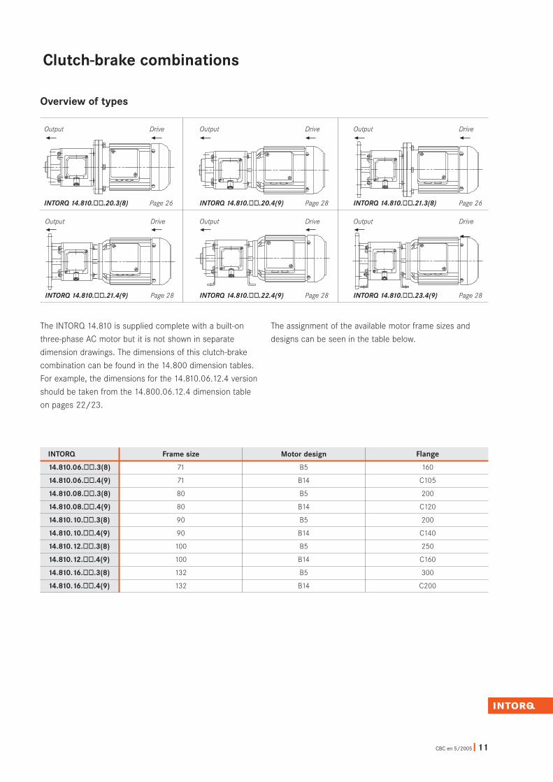
The INTORQ 14.810 is supplied complete with a built-on
three-phase AC motor but it is not shown in separate
dimension drawings. The dimensions of this clutch-brake
combination can be found in the 14.800 dimension tables.
For example, the dimensions for the 14.810.06.12.4 version
should be taken from the 14.800.06.12.4 dimension table
on pages 22/23.
The assignment of the available motor frame sizes and
designs can be seen in the table below.
CBC en 5/2005 ❚ 11
◊ ◊ ◊ ◊
◊ ◊◊◊
◊ ◊
◊◊
Output Drive
INTORQ 14.810.òò.20.3(8) Page 26
Output Drive
INTORQ 14.810.òò.20.4(9) Page 28
Output Drive
INTORQ 14.810.òò.21.3(8) Page 26
Output Drive
INTORQ 14.810.òò.21.4(9) Page 28
Output Drive
INTORQ 14.810.òò.22.4(9) Page 28
Output Drive
INTORQ 14.810.òò.23.4(9) Page 28
INTORQ Frame size Motor design Flange
14.810.06.òò.3(8) 71 B5 160
14.810.06.òò.4(9) 71 B14 C105
14.810.08.òò.3(8) 80 B5 200
14.810.08.òò.4(9) 80 B14 C120
14.810.10.òò.3(8) 90 B5 200
14.810.10.òò.4(9) 90 B14 C140
14.810.12.òò.3(8) 100 B5 250
14.810.12.òò.4(9) 100 B14 C160
14.810.16.òò.3(8) 132 B5 300
14.810.16.òò.4(9) 132 B14 C200
Clutch-brake combinations
Overview of types

12 ❚ CBC en 5/2005
Clutch-brake combinations
Dimensioning
Selecting the frame sizeDimensioning is carried out in accordance with VDI
Guideline 2241.
Symbols used in calculations:
MK Rated torque of the clutch or brake in Nm
Mload Load torque in Nm
Ma Acceleration or deceleration torque in Nm
Mreq Required torque in Nm
P Drive power in kW
∆no Initial relative speed of the clutch or brake in rpm
Jload Moment of inertia of all output components
reduced to the clutch shaft in kgm2
t3 Slipping time in seconds during which there is a
relative movement between the drive and output if
the clutch or brake is closed
t11 Engagement delay time in seconds, i.e. the time
from switching the voltage on to experiencing an
increase in torque
t12 Torque rise time in seconds, i.e. the time from the
start of the torque increase until rated torque MK is
reached
t1 Engagement time in seconds, i.e. the sum
of t11 + t12
t2 Disengagement time in seconds, i.e. the time from
switch-off until 10% of characteristic torque MK is
reached
K Safety factor � 2
Q Calculated switching energy per switching cycle in J
QE Max. permissible switching energy for one
switching operation in J, in accordance with the
table on page 18
Qperm Max. permissible switching energy in J
Sh Operating frequency in rph, i.e. the number of
working cycles distributed evenly over the time
period
ZNA Number of switching operations until readjustment
The required frame size is dimensioned essentially in
accordance with the required torques or braking torques.
The inertias to be accelerated or braked (moments of
inertia), the relative speeds, the acceleration or
deceleration times, the required operating frequencies and
the desired service life should all be included in the
calculation. The ambient conditions for the site of use of
housing clutches should be known. Such conditions would
include, for example, extraordinary ambient temperatures,
extremely high air humidity and dust accumulation.
Friction surfaces must always be kept free of oil andgrease.

Acceleration and delay timeIf the rated torque is specified and the moment of inertia
and load torque are both known, the acceleration or delay
time can be determined as follows:
Load typesIn practice, the following load types mainly occur:
❚ Dynamic and static loadThe majority of applications belong to this mixed
category, as a dynamic load is present in addition to a
static load torque in most cases.
The required frame size is usually calculated using the
clutch or acceleration process.
❚ Purely dynamic loadA purely dynamic load is present when flywheels, rolls or
similar are to be accelerated or decelerated and the
static load torque is negligible.
CBC en 5/2005 ❚ 13
Clutch-brake combinations
Dimensioning
Safety factorIn order to achieve the required transmission security even
in extreme operating conditions, the calculated torque is
multiplied by safety factor K. The value of K is determined
by the operating conditions.K � 2
Mreq =Jload · ∆n0 · K
9.55 · $t3 - t12%2
Ma =Jload · ∆n0
9.55 · $t3 - t12%2
Mreq = Jload · ∆n0 � Mload · K
9.55 · $t3-t12%2
T I
t3 =Jload · ∆n0
�t12
9.55 · (MK � Mload) 2
–Mload = engage clutch or accelerate
+Mload = brake or decelerate
Mreq. = (Ma � Mload) · K � MK
Mreq = Ma · K � MK
Estimated required torque or frame sizeIf only the drive power to be transmitted is known, the
required torque or braking torque can be determined as
follows:
+Mload = engage clutch or accelerate
–Mload = brake or decelerate
Mreq = 9550 P · K � MKn

$ %
Selected clutch-brake combination:
INTORQ 14.800.10.11.1
With MK = 30 Nm
Calculation of the available switching energy per switching
cycle:
t12— assuming 0.03 s2
ExampleThe following technical data is known for a packaging
machine's positioning mode:
14 ❚ CBC en 5/2005
Thermal loadWhen dimensioning clutches and brakes, other important
factors to be taken into account are the switching energy
per switching cycle and the operating frequency. The
available switching energy per switching cycle (engaging
the clutch and braking) is calculated using the formula
below:
The permissible friction energy per switching cycle at a
given operating frequency can be taken from the diagram
on page 16. If the friction energy per switching cycle is
known, the permissible operating frequency can also be
taken from the diagram.
Q = Jload · ∆n0
2 ·
182.5
Jload = 0.01 kgm2 total
Mload = 6 Nm
∆no = 700 rpm
t3 =0.15 s
Sh = 4000 switching operations per hour
Ma = 6.1 Nm Mreq = (Ma � Mload) · K = (6.1 � 6) · 2 Mreq = 24.2 Nm
Ma =Jload · ∆n0
2 0.01 · 700
9.55 · $t3 –t12 %
=9.55 · (0.15 – 0.03)
2
Q = 0.01 · 7002
182.5 ·
Ordering exampleINTORQ 14.800.10.11.1
24 V DC, shaft Ø 19 mm/19 mm
$ %MK MK
MK � Mload MK � Mload�
Q = Jload · ∆n0
2 ·
182.5 $ %MK MK
MK � Mload MK � Mload� Q = 55.9 J30 30
30 � 6 30 � 6�
See the diagram (page 16) for Sperm depending on the
calculated switching energy.
The required operating frequency is permissible at the
calculated switching energy for the selected frame
size (10).
Clutch-brake combinations
Dimensioning

CBC en 5/2005 ❚ 15
Operating timesThe operating times listed in the tables apply to switching
on the DC side with a rated air gap and warm coil.
These are mean values whose leakage depends on the
rectification type and the air gap Sair.
Time concepts when engaging anddisengagingt11 = Delay timet12 = Rise time of torquet1 = Engagement timet2 = Disengagement time:t2 brake ; t11 clutcht2 clutch ; t11 brake
Exci
tatio
nEx
cita
tion
Rate
d to
rque
On
Off
On
Off
Clutch
0.1 MK 0.1 MK
Brake
Time t
Time t
Time t
Frame size INTORQ 14.800/810/852 to 867 and 14.137/138
E clutch E brake
t11 ≈ t2 t12 t1 t12 t1
06 20 35 55 25 45
08 25 70 95 30 55
10 35 85 120 50 85
12 50 120 170 75 125
16 65 145 210 85 150
Operating times in milliseconds
t2 t2
t11t11 t12
t1
Dimensioning
Clutch-brake combinations

16 ❚ CBC en 5/2005
Clutch-brake combinations
Selection table
❚ Standard voltage 24 V DC❚ 1) MK, in relation to = 100 rpm❚ 2) At 20°C
INTORQ MK1) P20
2) nmax QE Moments of inertia14.800 – 867 Nm W rpm J J x 10-5, kgm2
Armature Frame 14.105 Clutch Brake Rotor Armature Outputdesign size 14.115 plate shaft
06 7.5 15 11.5 3.6 x 10³ 11.9 4.2 0.7
With splined 08 15 20 16 6 x 10³ 26.6 13.9 2.4
armature 10 30 28 21 3000 10 x 103 78 41.4 6.5
plate 12 60 35 28 16 x 103 226 120 15.8
16 120 50 38 25 x 103 630 378 64
With 06 7.5 15 11.5 3.6 x 10³ 11.9 6.5 1.2
backlash-free 08 15 20 16 6 x 10³ 26.6 25.3 3.7
armature 10 30 28 21 3000 10 x 103 78 82.1 10.2
plate 12 60 35 28 16 x 103 226 241 23.3
16 120 50 38 25 x 103 630 800 85
INTORQ 14.800/810/852 ÷ 867 and 14.137/138
Perm
issi
ble
switc
hing
ene
rgy
Qpe
rm[J]
Operating frequency Sh [h-1]
Sizes

CBC en 5/2005 ❚ 17
Clutch-brake combinations
These values can be converted to other service lives and
speeds with the aid of the diagram. However, you should
ensure that force Fr max is not exceeded. If additional axial
forces are present, please inform us of them so that we
can perform a recalculation.
Shaft loads
The radial forces specified in the table relate to the centre
of the shaft ends. Fr max is the maximum permissible radial
force in relation to the shaft strength.
Force Frated underlies a bearing service life of
Lh = 10,000 hours at n = 1500 rpm.
Example:Frame size 08
Speed n = 500 rpm
Service life Lh = 5000 hoursF = 425 · 1.8 = 765 N < Fr max. = 900 N
F Permissible radial force in N
Fr max. Max. permissible radial force in N,
in relation to shaft strength
Frated Permissible radial force in N for Lh = 10,000 h
and n = 1500 rpm
k Correction factor from diagram
Frame Force Forcesize Fr max. [N] Frated [N]
06 600 325
08 900 425
10 1300 590
12 1900 870
16 2300 1350
INTORQ 14.800 INTORQ 14.810
Cor
rect
ion
fact
or
F = Frated · k � Fr max.
Speed n [rpm]
Lh=2000Lh=5000Lh=10,000Lh=20,000
500 1000 1500 2000 2500 3000
3.0
2.5
2.0
1.5
1.0
0.5

18 ❚ CBC en 5/2005
Clutch-brake combinations
Dimensions
Free drive and output shafts
Keyways to DIN 6885/1Centring to DR DIN 332
Output Drive
Feet Flange
Frame a b b3 c e f i s msize kg
06 100 80 85 3 115 10041.5
7 0.248.5
08 120 105 110 3 140 13055
9 0.365
10 140 130 140 4 165 16070
9 0.480
12 160 150 160 5 184 18082
11 0.792
16 185 185 195 6 215 22397.5
13 1.2117.5
Frame a2 b2 c1 c2 e2 f2 s2 msize j7 kg
140 95 115 3 0.406
160 11012 10
130 3.59
0.5
160 110 130 9 0.508
200 13012 9
1653.5
11.5 0.7
200 130 165 3.5 11 0.810
250 18022 15
215 4 13.5 1.1
200 130 165 3.5 11 0.812
250 18022 15
215 4 13.5 1.1
250 180 215 1.316
300 23022 15
2654 13.5
2.0
Clutch Brake b1 e1 d1 f1 g1 g2 h i1 k1 l1 s1 m
Frame MK P20 h8 k6 kgsize
Nm W W
11 63 35 183 2306 7.5 15 11.5 52 67
1410 90 89
71 42 197 30M6 3
14 71 42 230 3008 15 20 16 65 90
1910 112 95
80 52 250 40M8 4.5
19 80 62 280 4010 30 28 21 78 115
2419 140 110
90 72 300 50M10 8
24 100 72 324 5012 60 35 28 78 115
2820 167 136
112 82 344 60M10 13
28 112 82 380 6016 120 50 38 98 145
3820 210 158
132 102 420 80M12 25
INTORQ 14.800.òò.11.1(6) basic version

CBC en 5/2005 ❚ 19
Clutch-brake combinations
Dimensions
Free drive and output shafts
Order dataGeneral – Type designation with specification of frame
size and rated voltage
Diameters of drive and output shafts
If required – Diameters of drive and output flanges
Foot height
Backlash-free armature plate
[value in brackets in the type designation]
INTORQ Feet Drive B5 flange Output B5 flange
14.800.òò.10.1[6] – – –
14.800.òò.10.2[7] – ö –
14.800.òò.11.1[6] ö – –
14.800.òò.11.2[7] ö ö –
14.800.òò.12.1[6] – – ö
14.800.òò.12.2[7] – ö ö
14.800.òò.13.1[6] ö – ö
14.800.òò.13.2[7] ö ö ö
M16x1.5

20 ❚ CBC en 5/2005
Clutch-brake combinations
Dimensions
Drive, hollow shaft, B5 flange – free output shaft
Keyways to DIN 6885/1Keyways to DIN 6885/1JS9Centring to DR DIN 332
Output Drive
INTORQ 14.800.òò.10.3[8] basic version
Output flange
Frame a2 b2 c1 c2 e2 f2 s2 msize j7 kg
140 95 115 3 0.406
160 11012 10
130 3.59
0.5
160 110 130 9 0.508
200 13012 9
1653.5
11.5 0.7
200 130 165 3.5 11 0.810
250 18022 15
215 4 13.5 1.1
200 130 165 3.5 11 0.812
250 18022 15
215 4 13.5 1.1
250 180 215 1.316
300 23022 15
2654 13.5
2.0
Clutch Brake
Frame MK P20 a3 b1 b3 c3 d1 d3 e1 e3 f1 f3 g1 g2 i1 k3 l1 l3 s1 s3 g msize
Nm W W h8 H9 k6 G7 kg
140 95.2 11 11 115 35 146 23 M806 7.5 15 11.5
16052
110.210
14 1467
13010 4 90 89
42 153 3040 M6
109 2.5
160 110.2 14 14 130 42 184 30 M808 15 20 16
20065
130.214
19 1990
16510 4 112 95
52 194 4050 M8
11.59 4.5
200 130.2 19 19 165 4 62 217 40 M1010 30 28 21
25078
180.213
24 24115
21519
5140 110
72 227 5060 M10
13.59 7.5
200 130.2 24 24 165 4 72 251 50 M1012 60 35 28
25078
180.216
28 28115
21520
5167 136
82 261 6070 M10
M1211 12
250 180.2 28 28 215 82 294 6016 120 50 38
30098
230.220
38 38145
26520 5 210 158
102 314 8080 M12 M12 11 22

CBC en 5/2005 ❚ 21
Clutch-brake combinations
Dimensions
Drive, hollow shaft, B5 flange – free output shaft
Order dataGeneral – Type designation with specification of frame
size and rated voltage
Diameter of drive hollow shaft
Diameter of drive flange
Diameter of output shaft
If required – Diameter of output flange
Backlash-free armature plate
[value in brackets in the type designation]
INTORQ Drive B5 flange Output B5 flange
14.800.òò.10.3[8] ö –
14.800.òò.12.3[8] ö ö

22 ❚ CBC en 5/2005
Clutch-brake combinations
Dimensions
Drive, hollow shaft,B14 flange – free output shaft
Keyways to DIN 6885/1Keyways to DIN 6885/1JS9Centring to DR DIN 332
Output Drive
INTORQ 14.800.òò.11.4[9] basic version
Clutch Brake
Frame MK P20 a4 b1 b4 c4 d1 d4 e1 e4 f1 f4 g1 g2 h i1 k4 l1 l4 s1 s4 g msize
Nm W W h8 H9 k6 G7 kg
11 11 63 35 152 2306 7.5 15 11.5 105 52 70.2 5.5
14 1467 85 10 3 90 89
71 42 159 3050 M6 7 9 3
14 14 71 42 186 3008 15 20 16 120 65 80.2 7
19 1990 100 10 4 112 95
80 52 196 4058 M8 7 9 4.5
19 19 80 62 225 4010 30 28 21 140 78 95.2 8
24 24115 115 19 4 140 110
90 72 235 5070 M10 9 9 8
24 24 100 72 261 5012 60 35 28 160 78 110.2 8
28 28115 130 20 4 167 136
112 82 271 6080 M10 9 11 13
28 28 112 82 309 6016 120 50 38 200 98 130.2 10
38 38145 165 20 5 210 158
132 102 329 8097 M12 12 11 24
Output flange
Frame a2 b2 c1 c2 e2 f2 s2 msize j7 kg
140 95 115 3 0.406
160 11012 10
130 3.59
0.5
160 110 130 9 0.508
200 13012 9
1653.5
11.5 0.7
200 130 165 3.5 11 0.810
250 18022 15
215 4 13.5 1.1
200 130 165 3.5 11 0.812
250 18022 15
215 4 13.5 1.1
250 180 215 1.316
300 23022 15
2654 13.5
2.0
Feet
Frame a b b3 c e f i s msize kg
41.506 100 80 85 3 115 100
48.57 0.2
5508 120 105 110 3 140 130
659 0.3
7010 140 130 140 4 165 160
809 0.4
8212 160 150 160 5 184 180
9211 0.7
97.516 185 185 195 6 215 223
117.513 1.2
Frame size 06, 08, 10

CBC en 5/2005 ❚ 23
Clutch-brake combinations
Order dataGeneral – Type designation with specification of frame
size and rated voltage
Diameter of drive hollow shaft
Diameter of output shaft
If required – Diameter of output flange
Foot height
Backlash-free armature plate
[value in brackets in the type designation]
INTORQ Feet Output B5 flange
14.800.òò.10.4[9] – –
14.800.òò.11.4[9] ö –
14.800.òò.12.4[9] – ö
14.800.òò.13.4[9] ö ö
Dimensions
Drive, hollow shaft, B14 flange – free output shaft

24 ❚ CBC en 5/2005
Dimensions
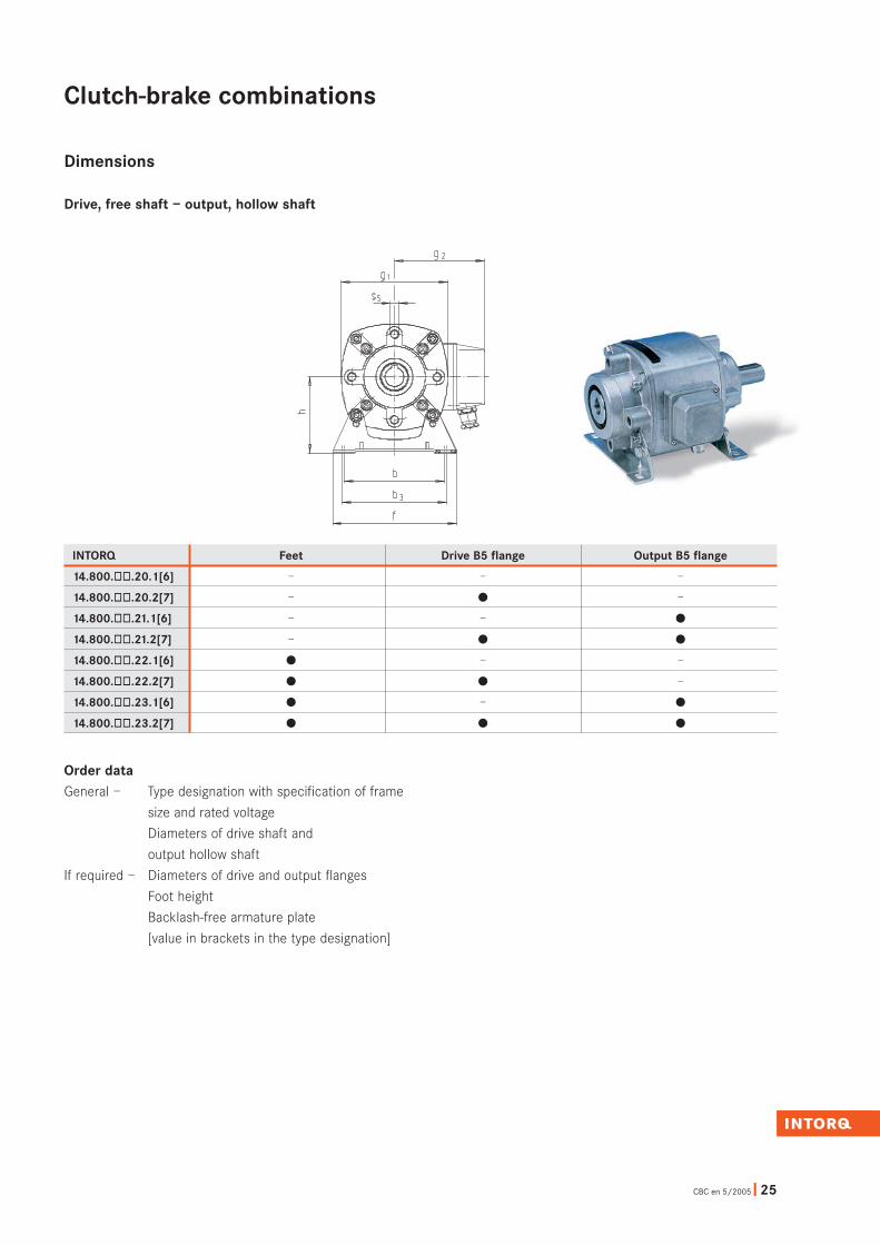
Drive, free shaft – output, hollow shaft
Keyways to DIN 6885/1Keyways to DIN 6885/1JS9Centring to DR DIN 332
Output Drive
Feet Drive flange Output flange
Frame a2 b2 c1 c2 e2 f2 s2 msize j7 kg
140 95 115 3 0.406160 110
12 10130 3.5
90.5
160 110 130 9 0.508200 130
12 9165
3.511.5 0.7
200 130 165 3.5 11 0.810250 180
22 15215 4 13.5 1.1
200 130 165 3.5 11 0.812250 180
22 15215 4 13.5 1.1
250 180 215 1.316300 230
22 15265
4 13.52.0
INTORQ 14.800.òò.22.1[6] basic version
Clutch Brake
Frame MK P20 b1 b5 d1 d5 e1 e5 f1 f5 g1 g2 h i1 i5 k1 l1 l5 s1 s5 msize
Nm W W h8 h8 k6 G7 kg
11 11 63 35 162 23 2306 7.5 15 11.5 52 52
14 1467 67 10 10 90 89
71 4214
169 30 30M6 M6 2.8
14 14 71 42 205 30 3008 15 20 16 65 65
19 1990 90 10 10 112 95
80 5217
216 40 40M8 M8 4.5
19 19 80 62 237 40 4010 30 28 21 78 86
24 24115 115 19 17 140 110
90 7217
247 50 50M10 M10 8
24 24 100 72 273 50 5012 60 35 28 78 98
28 28115 115 20 20 167 136
112 8220
283 60 60M10 M10 13
28 28 112 82 324 60 6016 120 50 38 98 120
38 38145 145 20 21 210 158
132 10225.5
344 80 80M12 M12 25
Frame a b b3 c e f i i6 s msize kg
41.506 100 80 85 3 115 10048.5
7 0.2
5508 120 105 110 3 140 13065
9 0.3
7010 140 130 140 4 165 16080
9 0.4
8212 160 150 160 5 184 18092
11 0.7
97.516 185 185 195 6 215 223117.5
13 1.2
Frame a5 b6 c5 c6 e6 f6 s6 msize H9 kg
140 95.2 115 0.406160 110.2
13 15130
4 90.5
160 110.2 130 M8 0.508200 130.2
14 18165
411.5 0.7
200 130.2 165 4 M10 0.810250 180.2
13 18215 5 13.5 1.1
200 130.2 165 4 M10 0.812250 180.2
16 21215 5 M12 1.1
250 180.2 215 1.316300 230.2
20 27265
5 M122.0
Clutch-brake combinations
CBC en 5/2005 ❚ 25
Order dataGeneral – Type designation with specification of frame
size and rated voltage
Diameters of drive shaft and
output hollow shaft
If required – Diameters of drive and output flanges
Foot height
Backlash-free armature plate
[value in brackets in the type designation]
INTORQ Feet Drive B5 flange Output B5 flange
14.800.òò.20.1[6] – – –
14.800.òò.20.2[7] – ö –
14.800.òò.21.1[6] – – ö
14.800.òò.21.2[7] – ö ö
14.800.òò.22.1[6] ö – –
14.800.òò.22.2[7] ö ö –
14.800.òò.23.1[6] ö – ö
14.800.òò.23.2[7] ö ö ö
Dimensions
Drive, free shaft – output, hollow shaft
Clutch-brake combinations

26 ❚ CBC en 5/2005
Dimensions
Drive, hollow shaft, B5 flange – output, hollow shaft
Keyways to DIN 6885/1JS9 Output Drive
INTORQ 14.800.òò.20.3[8] basic version
Clutch Brake
Frame MK P20 a3 b3 b5 c3 d3 d5 e3 e5 f3 f5 g1 g2 i5 k3 l3 l5 s3 s5 msize
Nm W W H9 h8 G7 G7 kg
140 95.2 11 11 115 23 M806 7.5 15 11.5
160 110.252 10
14 14 13067 5 10 90 89 14 125 40
30 10M6 2.5
160 110.2 14 14 130 30 M808 15 20 16
200 130.265 14
19 19 16590 4 10 112 95 17 159 50
40 11.5M8 4.5
200 130.2 19 19 165 4 40 M1010 30 28 21
250 180.286 13
24 24 215115
517 140 110 17 174 60
50 13.5M10 7.5
200 130.2 24 24 165 4 50 M1012 60 35 28
250 180.298 16
28 28 215115
520 167 136 20 201 70
60 M12M10 12
250 180.2 28 28 215 6016 120 50 38
300 230.2120 20
38 38 265145 5 21 210 158 25.5 238 80
80M12 M12 22
Output flange
Frame a5 b6 c5 c6 e6 f6 s6 msize H9 kg
140 95.2 115 0.406160 110.2
13 15130
4 90.5
160 110.2 130 M8 0.508200 130.2
14 18165
411.5 0.7
200 130.2 165 4 M10 0.810250 180.2
13 18215 5 13.5 1.1
200 130.2 165 4 M10 0.812250 180.2
16 21215 5 M12 1.1
250 180.2 215 1.316300 230.2
20 27265
5 M122.0
Clutch-brake combinations

CBC en 5/2005 ❚ 27
Order dataGeneral – Type designation with specification of frame
size and rated voltage
Diameter of drive hollow shaft
Diameter of drive flange
Diameter of output hollow shaft
If required – Diameter of output flange
Backlash-free armature plate
[value in brackets in the type designation]
INTORQ Drive B5 flange Output B5 flange
14.800.òò.20.3[8] ö –
14.800.òò.21.3[8] ö ö
Dimensions
Drive, hollow shaft, B5 flange – output, hollow shaft
Clutch-brake combinations

28 ❚ CBC en 5/2005
Dimensions
Drive, hollow shaft, B14 flange – output, hollow shaft
Clutch Brake
Frame MK P20 a4 b4 b5 c4 d4 d5 e4 e5 f4 f5 g1 g2 h i5 k4 l4 l5 s4 s5 msize
Nm W W H9 h8 G7 G7 kg
11 11 63 2306 7.5 15 11.5 105 70.5 52 5.5
14 1485 67 3 10 90 89
7114 131 50
307 M6 2.8
14 14 71 3008 15 20 16 120 80.2 65 7
19 19100 90 4 10 112 95
8017 161 58
407 M8 4.5
19 19 80 4010 30 28 21 140 95.2 86 8
24 24115 115 4 17 140 110
9017 182 70
509 M10 8
24 24 100 5012 60 35 28 160 110.2 98 8
28 28130 115 4 20 167 136
11220 211 80
609 M10 13
28 28 112 6016 120 50 38 200 130.2 120 10
38 38165 145 5 21 210 158
13225.5 253 97
8012 M12 24
Keyways to DIN 6885/1JS9 Output Drive
INTORQ 14.800.òò.22.4[9] basic version
Output flangeFeet
Frame a b b3 c e f i6 s msize kg
06 100 80 85 3 115 100 20.5 7 0.2
08 120 105 110 3 140 130 30 9 0.3
10 140 130 140 4 165 160 27 9 0.4
12 160 150 160 5 184 180 31 11 0.7
16 185 185 195 6 215 223 41.5 13 1.2
Frame size 06, 08, 10
Frame a5 b6 c5 c6 e6 f6 s6 msize H9 kg
140 95.2 115 0.406160 110.2
13 15130
4 90.5
160 110.2 130 M8 0.508200 130.2
14 18165
411.5 0.7
200 130.2 165 4 M10 0.810250 180.2
13 18215 5 13.5 1.1
200 130.2 165 4 M10 0.812250 180.2
16 21215 5 M12 1.1
250 180.2 215 1.316300 230.2
20 27265
5 M122.0
Clutch-brake combinations

CBC en 5/2005 ❚ 29
INTORQ Feet Output B5 flange
14.800.òò.20.4[9] – –
14.800.òò.21.4[9] – ö
14.800.òò.22.4[9] ö –
14.800.òò.23.4[9] ö ö
Order dataGeneral – Type designation with specification of frame
size and rated voltage
Diameter of drive hollow shaft
Diameter of output hollow shaft
If required – Diameter of output flange
Foot height
Backlash-free armature plate
[value in brackets in the type designation]
Dimensions
Drive, hollow shaft, B14 flange – output, hollow shaft
Clutch-brake combinations

50 ❚ CBC en 5/2005
Accessories
INTORQ 14.640.10.048 EDS 48 electronic dual switch
Application areaUsing 24 V standard excitation to switch:
❚ Clutch-brake combinations
❚ Other coils which are switched on the DC side in
alternating or parallel operation
The EDS 48 electronic dual switch is ideal for controlling
two coils.
FeaturesThe EDS 48 electronic dual switch contains the complete
power supply for a 24 V DC voltage coil and can be
operated using control voltages (e.g. from a PLC) or pulses.
A pulse at the START input switches the clutch on until a
pulse at the STOP input switches the clutch off and the
brake on. A program switch can be used to preselect the
type of brake to be controlled (electromagnetic or spring-
applied brake).
Note:When using spring-applied brakes, the transformer power
must be dimensioned for the sum of the clutch and braking
powers.
Delay times can be set on two potentiometers to prevent
clutches and brakes that do not have a common armature
element working in opposition. The input electronics are
potential-free and isolated from the power section by an
optocoupler.
For safety reasons, the clutch is always set to “off” and the
brake to “on” following mains connection or the closing of
switch a1. The device is able to execute the first start
command (clutch ON) approximately one second later. If a
start command is already present at the input before the
mains connection is made, the brake remains switched on
until a new start command is sent.
If required, switch a1 can serve as an “emergency-off”
switch.
EDS 48 dimensions
Technical dataStandard excitation 24 V
Input voltage 230 V, 50/60 Hz
Coil voltage 24 V
Max. coil power: With EDS 48 type 14.640.10.048 50 W
Max. operating frequency: Up to35 W Five switching
operations/s
Up to 50 W Two switching
operations/s
Connectable coils Two units
Max. control current at 24 V 10 mA approx.
Auxiliary supply at terminals 30 and 31 15 V
Max. current of the auxiliary supply 30 mA
Max. delay time 250 ms
Control pulses ≥ 3 ms
EDS 48 weight 1.8 kg
Control options❚ PLC (programmable logic controller)
❚ Contacts
❚ NPN (PNP) proximity switch
❚ NPN (PNP) photoelectric barriers
3550
6.5
4.550 100
10030
130“
“
“
“”
”
“ “
“
“
“ “
””

CBC en 5/2005 ❚ 51
Accessories
INTORQ 14.640.10.048 EDS 48 electronic dual switch
Connection examplesControl via continuous signals
Switching via contact
Fig. 1
Switching via optocoupler
Fig. 2
Switching via proximity switch
Fig. 3
Switching via PLC
Fig. 4
Pressing the a2 switch turns the brake “off” and the clutch
“on” (start), if a1 is not closed. If a2 is opened, the clutch
switches “off” and the brake “on” (stop). The first start
command is executed no earlier than approximately
1 second after the mains voltage is switched on or after a1
is opened.
This example is as Fig. 1, but an optocoupler or a transistor
is used instead of a contact.
This example is as Fig. 1, but a PNP proximity switch is
used instead of a contact.
Colours: bk. = black/bl. = blue/br. = brown
Proximity switch damped = clutch “on”/brake “off”
Proximity switch free = brake “on”/clutch “off”
In this example, a PLC with a control voltage of 10 to 30 V
is used for control.
Control voltage “on” = clutch “on”/brake “off”
Control voltage “off” = brake “on”/clutch “off”
CautionThe cables to the coil must not short-circuit or have a
conductive connection to earth (electrical bonding), the
PEN conductor or other coils.

52 ❚ CBC en 5/2005
Accessories
INTORQ 14.640.10.048 EDS 48 electronic dual switch
Connection examplesControl via pulses
Switching via contacts
Fig. 1
Switching via optocoupler
Fig. 2
Switching via proximity switch
Fig. 3
Example of pulse control
Fig. 4
Pressing switch a2 switches the clutch “on” (start), if a1 is
not closed. The pulse must be ≥ 3 ms and is saved until
switch a3 is closed for at least 3 ms (stop). If a3 remains
closed and switch a2 gives the start command, the brake
switches “off” and the clutch “on”.
This example is as Fig. 1, but an optocoupler or transistors
are used instead of contacts.
This example is as Fig. 1, but NPN proximity switches (e.g.
type 14.666.03.001, three-wire version) are used instead of
contacts.
Colours: bk. = black/bl. = blue/br. = brown
A cutting blade is driven by a cam.
Proximity switch a3 (type 14.666.03.001) should cause it
to stop automatically after one revolution following the
start pulse. The start command is issued via switch a2.
Clutch ≥ 3 ms
Brake ≥ 3 ms
Engage clutch
≥ 3 ms
≥ 3 ms
Brake
Brake
Engage clutch≥ 3 ms
≥ 3 ms
Start
Stop
Shears

CBC en 5/2005 ❚ 53
Accessories
E clutch – E brake version
Two
spar
k su
ppre
ssor
sIN
TORQ
14.
198.
00.0
1-24
VBrake coil
Clutch coil
Clutch is energised to engageBrake is energised to engage
INTORQ 14.198.00.0ò universal spark suppressorThe universal spark suppressor limits the induced voltages
which occur when switching off all clutches and brakes on
the DC side to safe values. Otherwise, these induced
voltages might damage coils and switches. Therefore, VDE
0580 requires appropriate protective measures to avoid
excessive switch-off surges and overvoltages.
Four versions of the universal spark suppressor are
available for the following voltage ranges:
DC switchingThe performance of both the clutch and brake coils must
be taken into account when dimensioning a transformer
rectifier.
DC switching means short switch-on and switch-off times,
but requires a spark suppressor to protect the contacts
against high induced voltages during switch-off.
DC switching
Connection example
Type Coil voltage Coil powerU Pmax
INTORQ 14.198.00.01 24 V – 50 V 110 W
INTORQ 14.198.00.02 50 V – 120 V 110 W
INTORQ 14.198.00.03 120 V – 200 V 110 W
INTORQ 14.198.00.04 200 V – 250 V 110 W

54 ❚ CBC en 5/2005
Accessories
DEG and DOSS high-speed switchgear
High-speed operation with INTORQ14.621.14.(16)òòò DEG double European deviceWorking in conjunction with DEG high-speed switchgear,
the clutch-brake combinations achieve excellent
positioning accuracy.
The 24 V coils on the housed clutches can be connected
to the DEG device on a 220 V/240 V mains.
The coil current (two coils up to a maximum of 100 W) is
switched by semiconductors and is free of wear; DEG
devices are controlled via auxiliary contacts, control
voltages or proximity sensors.
DEG high-speed switchgear is dimensioned as a constant
current source. The rated current flows in the solenoids
regardless of whether the coil is cold or warm. The torque
remains the same whether the operating status is cold or
warm.
We supply DEG high-speed switchgear as built-in units.
Control with one contact Control with PLC or control voltageControl with two contacts
DOSS double high-speed switchgearINTORQ 14.621.13.òòò
We recommend the DOSS double high-speed switchgear
for applications in which start/stop pulses are used for
control.
The switchgear mentioned above can be found in our
“Electronic Switchgear and Accessories” catalogue which
is available on request.
Connection examples
INTORQ14.621.14.(16)òòò INTORQ 14.621.13.òòò

CBC en 5/2005 ❚ 55
Our customers can reach us at any time from
anywhere in the world. We work with Lenze's
network of worldwide sales offices and
Service Centres.
Our helpline (008000 24 46877) will provide
you with expert advice, 24 hours a day,
365 days a year.
Information about our products, catalogues
and Operating Instructions can be found at
www.intorq.de.
Contact Lenze Service Centres and sales
partners via the Lenze website at
www.Lenze.com.
INTORQ – Sales andservice around the world

INTORQ GmbH & Co. KG
Postfach 1103
D-31849 Aerzen
Wülmser Weg 5D-31855 Aerzen
Tel +49(0)5154/9539-01Fax +49(0)5154/9539-10E-mail [email protected]
setting the standard
www.intorq.de
1304
1807
Su
bjec
t to
tec
hnic
al a
ltera
tions
❚Pr
inte
d in
Ger
man
y 5.
2005
en
❚5 4
3 2
1