electron accelerators for radiation processing
TRANSCRIPT

“Low energy electron beams for industrial and environmental applications” EuCARD-2 Workshop with Industry
8-9 December 2016, Warsaw Poland
Electron accelerators for radiation processing - reliability and
economical aspects
Z. ZimekCentre for Radiation Research and TechnologyInstitute of Nuclear Chemistry and Technology,
Warsaw, [email protected]

2
Accelerator technology for radiation processing

Up to 3.000 accelerators have been build for radiation processing (total number of accelerators applied in science, medicine and industry amounts approximately 30.000).
Accelerator technology development is based now on new constructions and new components, what leads to progress in:
Accelerator technology perfection (higher electrical efficiency, cost reduction);
Reliability according to industrial standards; Accelerators for MW power beam level; Compact accelerator constructions; Very low energy, powerful accelerators.

Industrial application of electron acceleratorsPolymer modification
Flame resistant cablesThermo-shrinkable productsCuring of tire cordFoam sheetsArtificial leatherFilms for coatings and packaging
Sterilization/ Disinfection
Sterilization of medical productsPreservation of spices, foodDisinfection of grains
Environmentalprotection
Flue gas purificationWater/wastewater treatment
Others Curing/coating of wood, paper etc.SemiconductorsCeramic composites

Penetration [g/cm2] =0.37(Energy [MeV]-0.2)for one side treatment and equal entrance and exit doses
Productivity [kg/h] = 3600 x Power [kW] xUtilization efficiency/Dose [kGy]
Average beam power
Electron energy
Although there are many different types of accelerators offering a wide range of performances ratings, only few would be suitable for particular application (Marshall R. Cleland, 1992).
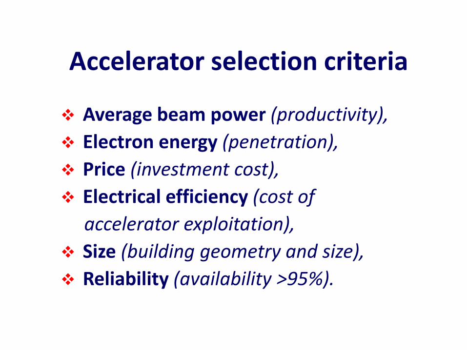
Accelerator selection criteria
Average beam power (productivity),
Electron energy (penetration),
Price (investment cost),
Electrical efficiency (cost of
accelerator exploitation),
Size (building geometry and size),
Reliability (availability >95%).

Electron accelerators for radiation processing (current ratings)
Accelerator type Parameter
Direct DC
UHF 100 - 200
MHz
Linear microwaves 1.3–9.3 GHz
Av. Beam current
Energy range
Beam power
Electrical efficiency
<2 A
0.05–5 MeV
~500 kW
60 – 80 %
<100 mA
0.3–10 MeV
700 kW
20 – 50 %
<30 mA
2–10 MeV
150 kW
10 – 20 %

Direct accelerators(transformer type)

Direct accelerators: principle of operation
−
+U
Vacuum envelope
Cathode
Electron gun
Anode
Beam exit window

Permanent sealed, compact ebeamaccelerators
Guaranteed 8000 operatinghours. High voltage of 80 to 300 kV. Beam intensity variation typically +/-5 % (specification +/- 10 %).
Hermetically sealed by brazing and welding. Can be refurbished by milling out frame with window foil and welding in new one.
ebeam Technologies,
Switzerland

RPC
“BroadBeam®”

Typical data for EC-scan 120kVAccelerating voltage: 80 – 120 keVBeam current 0 - 200 mA Working width: max 600 mm Throughput: 9000 kGy m/min at 150 keVWeb speed: 10 – further m/min

ELECTRON-BEAM ACCELERATORS FOR NEW APPLICATIONS
Operating characteristics EC-beam - Acceleration voltage 75 - 250 kV - Electron current 0 - 2000 mA - Working width 400 - 3000 mm - Throughput 14000 kGy m/min - Distribution of dosage over working width < 10 % - No gas cooling of the electron exit window necessary.

ESI – “EZCure®“
100 – 300 keV
ESI CB-300
Energy Science Inc.

ELV 12 coreless transformer accelerator
Electron energy 1 MeVBeam power 400 kWFrequency 1000 HzOne power supply Three scanners
BINP, Russia

ELV 12 corelesstransformeraccelerator
Facility forwastewatertreatment

Pomorzany Power Station (Poland)Radiation facility for flue gas treatment (SO2 and NOx
removal): 270 000 Nm3/h; 0.8 MeV; 4 x 300 kW
Total beam power 1200 kW

MOBILE ACCELERATOR SYSTEM
eb-TECH

Resonance cavity accelerators
single pass or multi-pass systems

Single cavity accelerators: principle of operation
„ILU” type family „Rhodotron” type family

ILU type accelerators, BINP, Russia
Ratings ILU-6 ILU-8* ILU-10 ILU-12**
ILU-14**
ElectronEnergy
0.5-2.5 MeV
0.8-1 MeV
4-5 MeV
5 MeV 7.5 – 10 MeV
Beam Power
20 kW 20 kW 50 kW 100/300 kW
100 kW
*Local shield weight 76t
**Multi cavity system

ILU 6 electronaccelerator at
pilot plant radiation facility
INCT, Poland
Energy 0.5-2.0 MeVBeam power up to 25 kWPulse duration 0.4 msRepetition rate up to 60 HzScan width 980 mmFrequency 127 MHz
Scanner
Resonator

ILU-10 in Radpol SA, Poland, 2008
Energy 5 MeV; beam power 50 kW;
Treatment of polymer pipes (heat shrinkable tubes);
Treatment of cables and wires;
Movable accelerator between two technological lines.

ILU 12
Coupling cell
1 – vacuum tank, 2 – copper toroidal cavity, 3 – magnetic lens, 4 – ion pumps, 5 – grid-cathode unit, 6 – outlet device, 7– coupling loop support, 8 – vacuum capacitor, 9 – RF generators.
ILU 10

Energy, MeV 10 7.5
Accelerating structureefficiency, %
61 77
Total efficiency, % 26 32
ILU 14 accelerator 10 MeV, 100 kW at sterilization facility, Russia
A.Bryazgin, INP, Russia
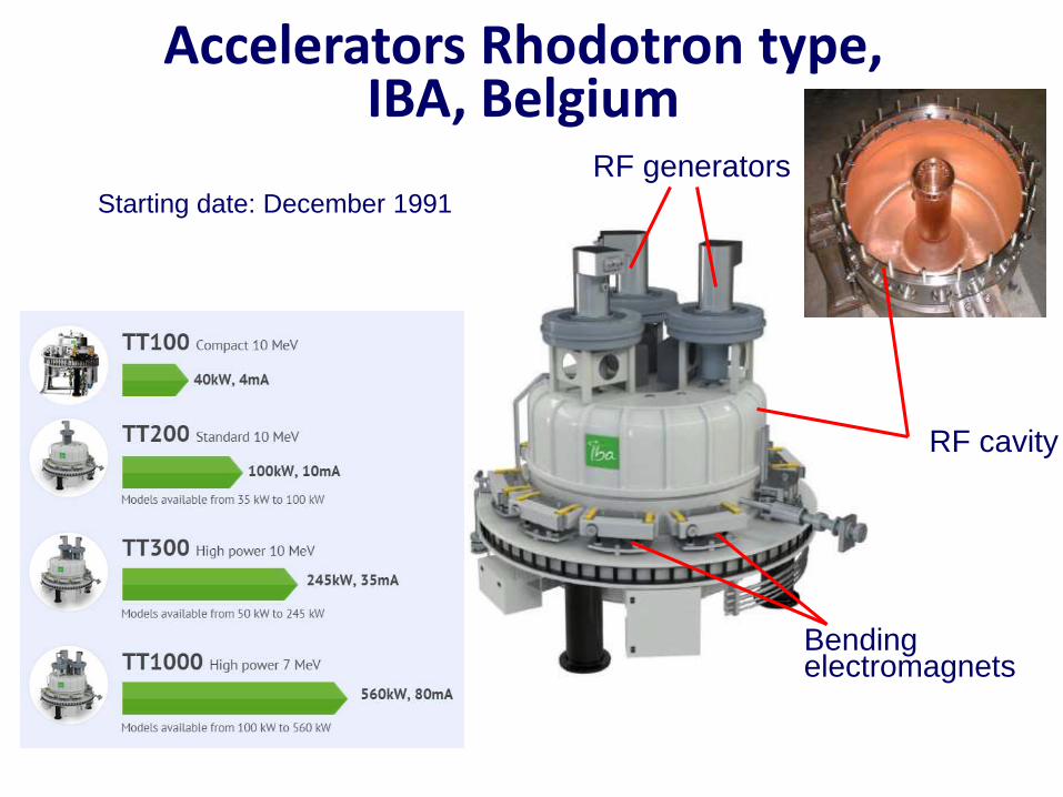
Accelerators Rhodotron type, IBA, Belgium
RF cavity
RF generators
Bending electromagnets
Starting date: December 1991

RHODOTRONTT 300,
IBA, USA
Electron energy:
5-7 MeV
Beam power:
200 kW
EB and X-ray options

Rhodotron: design and operation principles
Parallel operation
X-ray
EB
M. Abs, J. Brison, P. Dethier, IBA

RHODOTRON, TT1000, IBA
7 MeV, 560 kWSwitzerland
X-Ray (Dose 25 kGy)product density 0.15 gr/cc, Productivity 560 kW; 7 MeV,
15.5 m³/h,8000/rok (9% for service)
124,000 m³.Gamma equivalent 4.4 MCi gamma Co60.

Linear electron accelerators

Linear accelerator
with traveling wave
Peb = E xIav
Ip x τ = Iav x 1/F
Peb – beam powerE – electron energyIav – av. beam currentIp – pulse beam currentF – repetition rate
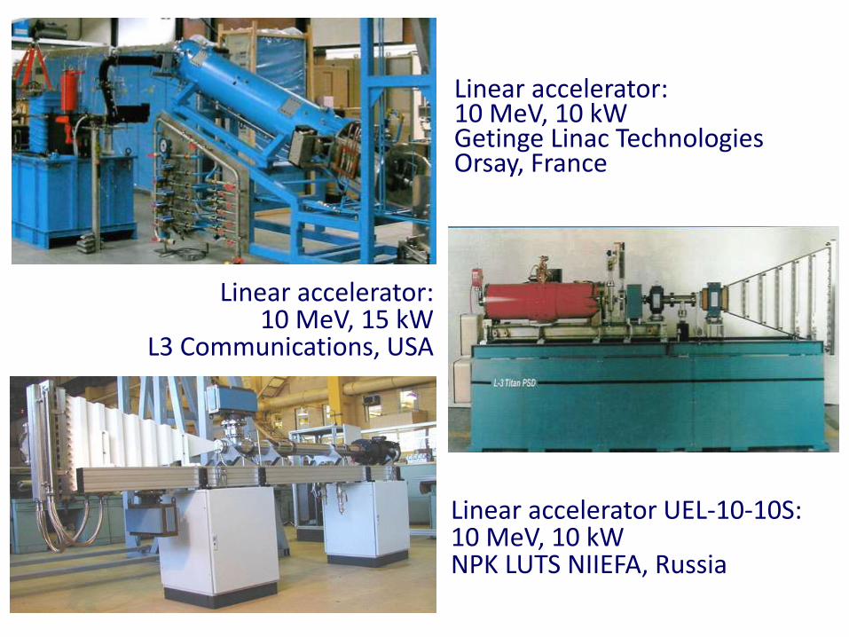
Linear accelerator UEL-10-10S: 10 MeV, 10 kW NPK LUTS NIIEFA, Russia
Linear accelerator: 10 MeV, 10 kW Getinge Linac TechnologiesOrsay, France
Linear accelerator: 10 MeV, 15 kW
L3 Communications, USA

The main features: Horizontally located accelerator, monorail conveyor, Two sides irradiation during one pass, Radiation shielding: concrete blocks (volume 360 m3);
facility spot: ~240 m2, Solid-state modulators for klystron and electron gun,
power line <75 kW, Control of electron energy, beam current and scan length, Throughput: 20-30 kGy; 55 boxes/h (40 x 40 x 60 cm3, 19 kg).
10 MeV, 10 kW linac
CoRAD, St Petersburg, Russia

Radiation sterilization facility, 10 MeV, 15 kW, INCT, Poland
Elektronika 10/10, „Torij”, Russia

New accelerator developments for
radiation processing

eFFAG – compact CW recirculating electron accelerator
(Fixed-Field Alternating Gradient)
Injectionorbit
Extractionorbit
50 keV to 9 MeV compactring with injection and extraction orbits.Outer radius <50 cm
FFAGs
- Fixed magnetic fields like cyclotron,
- Separated components,
- Synchrotron-like dynamics.C. Johnstone, 2014
Permanent magnets based on ceramic ferrites:
SmCo5 or NdFeB could be used.

37
Compact, 1 m diameter, transportable,High current – 1-2 mA,No power supplies for magnets,Inexpensive components.
A single 100-200 keV cavity (as in cyclotron),45-90 acceleration turns,Duty cycle: 1ns/10 ns ~10%,Space charge limited to ~109 electrons/RF bunch For 100 MHz cavity (10 ns bunch spacing),Electron energy 9 MeV, Beam current 1.6 mA, Average beam power ~140 kW.
Market case for compact CW effags

Beam energy: 1 MeVBeam current: 25 mAMaximum beam power: 25 kWDimensions: 0.5x0.9x1.4 m Gun/klystron HV: 15 kVPower consumption: ~75 kWElectrical efficiency: ~33%
Compact CW linac for radiation technologies
CW multi-beam
klystron KU-399A
D.S. Yurov et al.,
RuPAC 2012

Superconducting Radio Frequency compact, high power, electron
linac 2-40 MeV, 100 kW 1 2 3
4
5
6
7
1. Electron gun
2. Superconducting linac
3. Bending magnet
4. Scanning magnet
5. Output chamber
6. Microwave power
7. Helium cryoplant
NIOWAVE Inc.
350 MHz, 3 accelerating gaps
Electron bunch length 5 ps

Reliability/availability of industrial accelerators
40

RELIABILITY: PROBABILITY that a system can perform its intended function for a specified time interval under stated conditions.
High reliability is required when repair of sensitive sub-components are long (or difficult)
AVAILABILITY: fraction of TIME during which a system meets its specification.
High availability is required if continuous service is priority.
41

Low availability
Prototype accelerator construction (limited exploitation experience),
Parameters on the edge of present limits (unproven working conditions),
Components with limited life time (magnetron)
Difficulties in spare parts availability (limited access),
Poor accelerator reliability (improper design and poor quality components).
42

Quality requirements
Quality of components and subsystems,
Design quality,
Quality of exploitation and servicing.
Parallel efforts are necessary regarding: components, design, exploitation and servicing quality to achieve suitable accelerator availability (reliability). Share reliability experience policy is also needed.
43

Reliability chain
Designquality
Compo-nents quality
Qualifiedoperation
Qualifiedmain-
tenance
Successful
exploitation
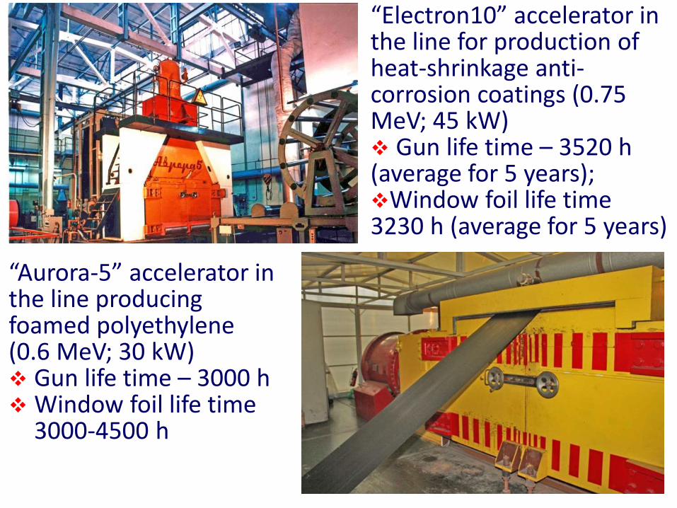
“Aurora-5” accelerator in the line producing foamed polyethylene (0.6 MeV; 30 kW) Gun life time – 3000 h Window foil life time
3000-4500 h
“Electron10” accelerator in the line for production of heat-shrinkage anti-corrosion coatings (0.75 MeV; 45 kW) Gun life time – 3520 h(average for 5 years);Window foil life time3230 h (average for 5 years)

Exploitation of accelerator facility
Irradiation (95-98%), Regular maintenance activity (per day, week, ½ year), Servicing due to unexpected break downs.
Maintenance and service principles
Personnel qualification, In house activity (maintenance and servicing), Service provided by accelerator manufacturer.
Maintenance procedures
Regular replacement of water and air filters, Regular replacement of belts, hoses, lubricants, Vibration/frequency analysis of rotating
equipment (3 months cycle), IR detection of electrical connections (3 years cycle),
Cleaning of HV cables and components (½ year),
Repair procedures
Fault detection and diagnosis process, Preparation time needed to start the repair, Fault correction, Post-repair parameters verification, Restart of the system.

Second hand accelerators
Safe industrial electron accelerators operation in extended period of exploitation became a question after 30 years long period in service. It is due to sometime second hand accelerators are offered on the market. The evaluation should be performed to establish critical parameters like:Accelerator reliability (availability), Access to the spare parts and cost of accelerator
servicing, Safety interlocks condition and reliability, Quality of cables, wires and rubber tubes which are
irradiated by scattered radiation (in some cases replacement is needed in 10-15 years intervals).

Long accelerators exploitation
Positive answer on above topics may allow on successful accelerator exploitation in extended period of time. Such evaluation should be repeated in 2-5 years period to avoid rapid change in accelerator availability.
More conservative direct (transformer) accelerator construction is better suited for longer exploitation period to compare with microwave linacs where microwave components with limited life period are applied. Progress in development of microwave components creates difficulties in access to old fashioned spare parts.

Economical aspects
49
Cost reduction is one of the key factors of successful radiation technology implementation.
Annual cash flow projections are common techniques used for analyses of economic option.
Economical analysis based on annual fixed and variable costs evaluation is very useful to recognize accelerator facility economical condition.
50

15 %30 %20 %5 %
10 %10-20 %
10 %3/5 %
~120 %
Ki = 2,2 Kacc
Estimated investment costs referred to electron accelerator price
Shielding walls, ventilation Building with armature Technological equipment Process control system Design and permission Installation and validation Amortization (10 years) Service costs (fixed/variable)
Total

Annual amortization costs
Ka = Ki {i /[ 1 – (1 + i)-n]}where:Ki – investment costs,i – capital interest [%], n – facility usefulness [years],
for: i = 8 %; n = 15 years Ka = Ki 0,117
for: i = 8 %; n = 5 years Ka = Ki 0,25
Amortization is the process of decreasing for an amount over a period
52

Capital costs (investment)Direct costs The preparation of the stand; Construction of the building; Technological equipment;…
53
Indirect costs Project management; Facility design; Reserve;…

Exploitation costsVariable costs Labor (exploitation, supervision); Electricity, water, pressured air, others; Spare parts;…Fixed costs:
Administrative costs with overheads;
Security, amortization, credit;
Taxes including land tax;
…54

619
350 260 216
0
200
400
600
800
1 2 3 4
Number of Shifts
Co
st
Ra
te in
US
D/h
55
Cost rate of one beam hour

Factors influence pay back period
Scenario Description Pay back period in years
Postulated According to plan
5
Low service cost -20 % 8
Higher work time 4800 h/year 4
Lower work time 3200 h/year 7
Low efficiency -20 % 6
Higher investment cost +10 % 6
Delayed start up 3 months 656

In general, electron beam technology seems to have the low operating cost despite its moderate to high capital costs. The high capital cost of technology may be compensated by its relatively low annual operating costs.
Full set of technical information should be collected to describe accelerator quality and evaluate the risk connected with certain accelerator design. Disadvantages and advantages should be discussed in details to optimize a final decision regarding accelerator selection.
57

CONCLUSIONSCharacteristics steps can be recognized in the past of
accelerator development. Present stage of accelerator technology perfection includes: cost effectiveness, reliability, compactness and introduction of MW beam power level.
Demands coming from growing fields of radiation processing technology implementation have a strong impact on R&D process of accelerator technology.
Any practical accelerator construction must be compromise between size, efficiency and cost.
The electrical efficiency is important parameter for high power accelerators. Special attention should be devoted to optimize electrical energy consumption for accelerator and auxiliary equipment installed in radiation facility.

The most important tool for each application is not the accelerator but the beam. Radiation facility must satisfy the beam specifications for a given application.
Initial capital cost, operating cost and reliability of the radiation facility play an crucial role in any industrial (for-profit) applications.
Users are always interested in lower total cost, so new technologies to increase the return on investment are always welcome.
New systems must be proven in an industrial confirmed acceptance, so introduction of a new accelerator technology can require a number of years for widespread market penetration.
Increasing application of high energy accelerator for sterilization of medical products due to increased cost and shortage of Co-60.

Increasing interest to X-Rays processing.Major industrial accelerator producers are located in USA,
Russia, Japan, France and Belgium. Several other countries including Poland are capable to produce accelerators on limited scale.
The R&D program of accelerator technology perfection is tightly connected to progress in development of advanced technology in many branches of technical activity (power components, control systems).
New accelerators constructions can frequently offer better economic and technical characteristics but only long time operation can revile weak points of certain accelerator construction in practical industrial conditions
The progress in accelerator technology is not a quick process but can be easily noticed in longer time scale.

Prospects for Future Expansion
Many beneficial effects of radiation processing have been demonstrated:
The development of polymeric materials with new properties by application different materials.
Reduction of environmental pollution by degradation toxic compounds in air, water and soil.
Cracking crude oil to increase the yield of lighter compounds which are the most valuable products.
Increased sale of irradiated foods to reduce the use of toxic chemicals to control insects, and to reduce the risk of disease.
Recovery of rare metals, such as scandium from effluents of hot spring by radiation grafted fiber absorbent (radiation grafted fibers for recovery of uranium from sea water).
Radiation degradation of natural polymers, such as chitosan, starch and carrageenan to produce plant growth promoter and super water absorbent for improving agriculture.

Thank you
for your attention