electronic devices active filters · of active filters are: low pass filter, high pass filter, band...
TRANSCRIPT

ET Training
Electronic Devices Active Filters Instructor: H.Pham Email: [email protected]
0
f = 1/T
T
distance 0
time
Wavelength =V/F
Where V=3x10⁸ m/s
And F=hz


ET Training
Electronic Devices Active Filters Instructor: H.Pham Email: [email protected]
+
Time domain (Oscilloscope )
Pure of 1 kHz square-wave
Frequency domain (Spectrum Analyzer)
Picture of 1 kHz square-wave

ET Training
Electronic Devices Active Filters Instructor: H.Pham Email: [email protected]
A 1 kHz square wave
500 milliV/Div
200 usec/Div
On the oscilloscope
A 1 kHz square wave
100 milliV/Div
That shows on the spectrum analyzer

ET Training
Electronic Devices Active Filters Instructor: H.Pham Email: [email protected]
10/25/2018 5
• Filters are circuits that are capable of passing signals with certain selected frequencies while rejecting signals with other frequencies. This property is called selectivity.
• Active filters use transistors or op-amps combined with passive RC, RL or RCL circuits. The active devices provide voltage gain , and the passive circuits provide frequency selectivity. The four basic categories of active filters are: low pass filter, high pass filter, band pass filter, band stop filter (Notch filter )
1. LOW PASS FILTER
0 dB
fc f
Av(dB)=Vo/Vi
BW=Band Width
Ideal Response
-3 dB
0 dB
fc
Slope=-20dB/decade
10fc f
BW=Band Width
Av(dB)=Vo/Vi
Practical Response
ET Training
Electronic Devices Active Filters Instructor: H.Pham Email: [email protected]
10/25/2018 6
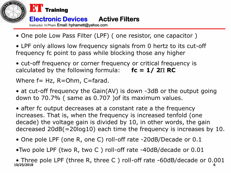
• One pole Low Pass Filter (LPF) ( one resistor, one capacitor )
• LPF only allows low frequency signals from 0 hertz to its cut-off frequency fc point to pass while blocking those any higher
• cut-off frequency or corner frequency or critical frequency is calculated by the following formula: fc = 1/ 2 RC
Where f= Hz, R=Ohm, C=farad.
• at cut-off frequency the Gain(AV) is down -3dB or the output going down to 70.7% ( same as 0.707 )of its maximum values.
• after fc output decreases at a constant rate a the frequency increases. That is, when the frequency is increased tenfold (one decade) the voltage gain is divided by 10, in other words, the gain decreased 20dB(=20log10) each time the frequency is increases by 10.
• One pole LPF (one R, one C) roll-off rate -20dB/Decade or 0.1
•Two pole LPF (two R, two C ) roll-off rate -40dB/decade or 0.01
• Three pole LPF (three R, three C ) roll-off rate -60dB/decade or 0.001
ET Training
Electronic Devices Active Filters Instructor: H.Pham Email: [email protected]
10/25/2018 7
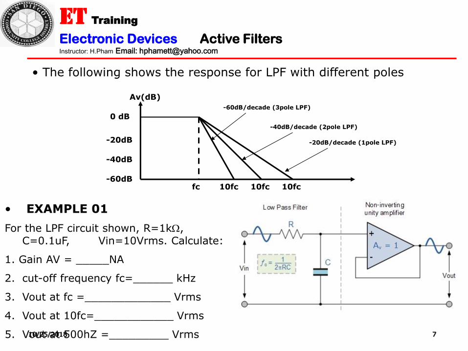
• The following shows the response for LPF with different poles
0 dB
fc
Av(dB)
-20dB/decade (1pole LPF)
10fc 10fc 10fc
-40dB/decade (2pole LPF)
-60dB/decade (3pole LPF)
-20dB
-40dB
-60dB
• EXAMPLE 01
For the LPF circuit shown, R=1k, C=0.1uF, Vin=10Vrms. Calculate:
1. Gain AV = _____NA
2. cut-off frequency fc=______ kHz
3. Vout at fc =_____________ Vrms
4. Vout at 10fc=____________ Vrms
5. Vout at 500hZ =_________ Vrms

ET Training
Electronic Devices Active Filters Instructor: H.Pham Email: [email protected]
10/25/2018 8
• EXAMPLE 02
For the LPF circuit shown, Given Vin= 2.5Vrms. Calculate:
1. Gain AV = (1 + R2/R1): ____ 2. cut-off frequency fc=____ Hz
3. Vout max =______ Vrms 4. Vout at fc=______Vrms
5. Vout at 10fc =_____Vrms
fc
Vomax
0.707xVomax
0.1xVomax
0.01xVomax
Vo AV(db)
10fc 100fc 20log10=10dB 20log0.707=-3dB
20log0.1=-20dB 20log0.01=-40dB
___dB
___dB
___dB
___dB
Complete AV(dB )

ET Training
Electronic Devices Active Filters Instructor: H.Pham Email: [email protected]
10/25/2018 9
2. ACTIVE HIGH PASS FILTER ( HPF )
• Pass any frequencies higher than cut-off frequency ( fc )
• Cut-off frequency formula is the same as LPF: fc = 1 / 2 R C
-3 dB
0 dB
fc fc/10 f
BW=Band Width
Or pass band
Av(dB)=Vo/Vi
HPF Response
-20 dB
-40 dB
• EXAMPLE 03
For the HPF circuit shown, Given Vin= 2.0Vrms, R=910,C=0.1uF. Calculate:
1. Gain AV = ____ 2. cut-off frequency fc=_____ kHz
3. Vout at fc =_____ Vrms 4. Vout at fc/10=______Vrms
5. Vout at 100hZ =________Vrms

ET Training
Electronic Devices Active Filters Instructor: H.Pham Email: [email protected]
10/25/2018 10
3. ACTIVE HIGH PASS FILTER ( HPF ) using Inverting Amplifier
• EXAMPLE 04
For the HPF circuit shown, Given Vin= 1.5Vrms, R1=1k, R2=2.7k,
C=10nF.Calculate:
1. Gain AV = ____ 2. cut-off frequency fc=_____ kHz
3. Vout max =______ Vrms 4. Vout at fc =_________Vrms
5. Vout at 1.59kHz =________Vrms

ET Training
Electronic Devices Active Filters Instructor: H.Pham Email: [email protected]
10/25/2018 11
4. Two Poles ACTIVE HIGH PASS FILTER ( HPF )
• 2 resistors R3, R4 and two capacitors C1, C2
• If R3=R4 and C1=C2 then cut-off frequency is FC = 1 / 2 RC

ET Training
Electronic Devices Active Filters Instructor: H.Pham Email: [email protected]
10/25/2018 12
5. BAND PASS FILTER (BPF ) 5. BAND PASS FILTER (BPF )

ET Training
Electronic Devices Active Filters Instructor: H.Pham Email: [email protected]
10/25/2018 13
5. BAND PASS FILTER RESPONSE
• Pass frequencies higher Fl and less than fH
• BW (bandwidth) = fH – fL fcenter=squareRoot ( f1xf2 )
• The quality Q=fcenter/BW
• Quality Q controls the roll-off rate and the bandwidth of the filter

ET Training
Electronic Devices Active Filters Instructor: H.Pham Email: [email protected]
10/25/2018 14

ET Training
Electronic Devices Active Filters Instructor: H.Pham Email: [email protected]
10/25/2018 15
6. BAND STOP (Notch) FILTER RESPONSE
• Pass frequencies less than Fl and higher than fH

ET Training
Electronic Devices Active Filters Instructor: H.Pham Email: [email protected]
10/25/2018 16

ET Training
Electronic Devices Active Filters Instructor: H.Pham Email: [email protected]
10/25/2018 17