electronic multimeter - radionerdsradionerds.com/images/c/c6/tm-11-5511.pdf · department of the...
TRANSCRIPT

DEPARTMENT OF THE ARMY TECHNICAL MANUAL
ELECTRONIC
MULTIMETER
TS.SOSjU
DEPARTMENT OF THE ARMY • J UNE 1951

DEPARTMENT OF THE ARMY TECHNICAL MANUAL
TM 11-5511
ELECTRONIC
MULTIMETER
TS-SOS/U
DEPARTMENT OF THE ARMY •
United States GOfiernmmt Printing Office
Washington: /95/
JUNE 1951

DEPARTMENT OF THE ARMY WASHINGTON 25, D. C., 8 Jwne 1951
TM 11-5511 is published for the information and guidance of all concerned.
[AG 413.6 (1 Jun 51)]
By ORDER OF THE SECRETARY OF THE ARMY :
OFFICIAL: J. LA WTON COLLINS WM. E. BERGIN Ohief of Staff, United States Army MajO?' General, USA Acting The Adjutant General
DISTRIBUTION:
Tech Svc (2) except 11 (65) ; Arm & Svc Bd (1) ; AFF Bd (ea Svc Test Sec) (1); AFF (5) ; AA Comd (2); OS Maj Comd (5) ; Base Comd (5); MDW (5); Log Comd (5); A (20); CHQ (2) ; FC (2); Sch (2) except 11 (25); Gen Dep (2); Dep 11 (20) except Sig Sec, Gen Dep (10) ; Tng Div (2) j PE (10), OSD (2) ; Lab 11 (5) ; 4th & 5th Ech Maint Shops 11 (3); Two (2) copies to each of the following TjO & E's: 11-107; 11-127; 11-500 CA, CB, CC; 11-587; 11-592; 11-597; SPECIAL DISTRIBUTION.
For explanation of distribution formula, see .SR 310-90-1.

CONTENTS
Paragraph Page
CHAPTER 1. INTRODUCTION. Section I. General.
Scope ......... .......... .............. .. .. ......... :... ........ .. ...... ......... ...... .... 1
Forms and records ...................... .. .......................... 2
II . Description and data. General ...................................... ..................... ......... ......... .. .. 3 3 Table of components parts ...... .. ... ................ ......... 4 4 Component parts, description and location 5 4 Accessory equipment .......... ..................... ....... 6 6 Technical characteristics ...... .................................... 7 6 Packaging data ....................... ... ..... .......... .... ......... ... 8 7
CHAPTER 2. OPERATING INSTRUCTIONS. Section I. Service upon receipt of equipment.
II.
Unpacking and checking new equipment... ... Unpacking and checking used or
recondition equipment .... ..................... ............... . Repacking .................................................................... .. ...... . . Location ..... ..................... .................................................... .
Controls and instruments . Controls ................................ .......................................... . Meter .......... .. ... ............................. . Panel connections .................. ................ .... ................... .
Ill. Operation under usual conditions. Preliminary start ing procedure ... .............. ............ . Measuring and reading doc voltages .............. . Measuring and reading a-c voltages ......... ..... . Measuring and reading resistance,
and adjusting ohms scale .... ..... . Stopping procedure .. .......... .. ... ... .. ............................... . Purpose and use of equipment
performance checklist .. .. ............. ..... .... .. .. ........... . Equipment performance checklist ...... ...... .
IV. Operation under unusual conditions. General .: ... ....... ..................................................................... . Batteries .... .... .................................................................... .
9 9
10 10 11 10 12 11
13 11
14 12 15 12
16 12 17 14 18 15
19 15 20 16
21 16 :i2 18
23 20 24 20

CHAPTER 3. MAINTENANCE INSTRUCTIONS. Paragraph Page
Sec/ion I. Lubrication and preservation. Lubrication ........................................................................... 25 21 Weatherproofing ............................. ..... .......................... 26 21 Rustproofing and painting ......... ...... .......... ........... 27 21
/I. Preventive maintenance services. Definition and importance of
preventive maintenance .. .. ..................... .............. 28 22 General preventive maintenance techniques 29 22 Specific preventive maintenance techn iques 30 22 Preventive maintenance checklist ................. ....... 31 23
CHAPTER 4. FIELD MAINTENANCE INSTRUCTIONS.
Sec/ion I. Theory of operation. Scope and application ........................................ ....... . 32 27 Block diagram ................................................... . 33 27 Power supply ............. ....................................................... . 34 29 Amplifier ........ .................................. ........ .. ......................... . 35 30 Indicating meter .... .......................................................... . 36 32 Switch section ................................................... ................. . 37 32 D -c probe .................................... ... ...................................... . 38 35 A-c probe ........................................... .. ........................... ..... . 39 35
II. Prerepair procedures. Tools, materials, and test equipment .. ......... . 40 37 Power requirements .................................................... . 41 37 Inspection ..................................................... ................. ....... . 42 37 Removal of pluck-out parts .................... ........ ....... . 43 38 Stripping ............. ........................................ ................. ........ .. . 44 39 Cleaning ................... ... ........................................ ..... .... ..... . 45 41
/II. Trouble location. Preliminary procedure .................................. ....... ...... . 46 42 Trouble-shooting procedures ............................. . 47 42 Gas checks ......................... .. ...................... ..................... ... . 48 43 General precautions ..................................................... . Trouble-shooting chart ............. ................ .......... : ... .. .. .
49 43 50 44
IV. Calibration procedures. General ........ .................................... ............... .......... .. ............ . 51 58 Setting zero controls ................................. .................... . 52 58 Replacement of a-c probe assembly ................. . 53 59
ii

Paragraph Page
v. Refinishing. Appearance .............................. .. . .... ................. 54 Refinishing after repair .. ............. ............ ...... 55
CHAPTER 5. SHIPMENT AND LIMITED STOUAGE AND DEMOLITION TO PREVENT ENEMY USE.
Section l. Shipment and storage.
61 61
Removal from service . . .... 56 63 Repacking for shipment or limited sto rage 57 63
II. Demolition to prevent enemy use.
Methods of demolition ..... .. .... ... . ... .. 58 63
D estruction of components ........... ..... .................... 59 64
APPENDIX I.
II.
UEFEUENCES
IDENTIFICATION TABLE OF PAUTS FOU ELECTUONIC MVLTIMETER TS·505 IV
INDEX ................................... .. .................. .. ....... ............... .
65
67
75
iii

f ill 5!1 11 - 1
Figllre I. Electronic MII/tim etc,. TS-505/U.
iv
CHAPTER I
INTRODUCTION
Section I. GENERAL
1. Scope
a. These instructions are published for the information and guidance ()f the personnel to whom this equipment is issued. They contain a physical description of the equipment; information on operation, organizational maintenance, theory, and field maintenance; instructions for removing the equipment from service and repacking for shipment or limited storage; and instructions for demolishing the equipment to prevent enemy use. These instructions apply only to Electronic Multimeter TS-505jU.
b. Appendix I contains a list of references, including supply catalogs, technical manuals on associated equipment, and other available publications applicable to the equipment. Appendix II contains an identification
table of parts.
2. Forms and Records
The following standard forms will be used for reporting unsatisfactory conditions of equipment, or improper preservation, packaging, packing, marking, loading, stowage, or handling thereof.
a. DD Form 6, Report of Damaged or Improper Shipment (Reports Control Symbols CS GLD-66 (Army), Sand A-70-6 (Navy), and AFMC-U2 (Air Force», will be filled out and forwarded as prescribed in
SR 745-45-5 (Army), NAV DEPT SERIAL 85POO (Navy), and AFR
71-4 (Air Force). b. DA AGO Form 468, Unsatisfactory Equipment Report (Reports
Control Symbol CS GLD-247), will be filled out and forwarded tv the Office of the Chief Signal Officer as prescribed in SR 700-45-5.
1

c. AF Form 54, Unsatisfactory Report, will be filled out and forwarded to Commanding General, Air Material Command, Wright-Patterson Air
Force Base, Dayton, Ohio, as prescribed in SR 700-4 5-5 and AFR 65 -26.
d. Use other forms and records as authorized.
Section II. DESCRIPTION AND DATA
3. General
a. DESCRIPTION OF ELECTRONIC MULTIMETER. (1) Electronic Mu lti
meter TS-505 / U is a general purpose a-c (alternating-current) and d-c ( direct-current) vacuum-tube voltmeter and a d-c ohmmeter. It is a selfcontained unit.
(2) The cover of the multimeter is attached with four spring catches (fig. 2). Two sets of test leads for use with the multi meter are contained ill the cover. The handle may be pivoted and locked into position to act as a stand , thus permitting the operator to place the multimeter at a
comfortable viewing angle (fig. 2) . Six screws are used to attach the
rear cover of the multimeter. These screws serve as legs which protect the meter case when it is placed in a horizontal position.
(3) The multimeter is made completely watertight by means of two
peripheral rubber gaskets (on the back and on the front of the front panel); by rubber gaskets behind the meter and the battery cover; and
by 0 rings, or washers, behind the potentiometers, the switches, the binding posts, and the pilot light indicator jewel.
b. PURPOSE AND USE. Electronic Multimeter TS-505 / U is used when testing electronic equipment. It permits the measurement of a-c and d-c
vo ltage and resistance over relatively wide ranges. c. EQUIPMENT FEATURES. (1) Voltag: s and resistances a re measured
by a specially ca librated milliammeter. The d -c and a-c voltages are read
on the outer arc (black) of the sca le (fig. 3). The resistance sca le is the second largest arc (green) . The zero center d-c scale is the third .large~ t
arc (blue). The 0- to 2-volt a-c range is the innermost arc (purple) . The meter is hermetically sealed .
(2) There are nine d-c voltage ranges which permit measurement of voltages from .05 to 1,000 volts. The appropriate voltage range is selecred with the RANGE switch . The input resistance is 20 megohms on :tll
d-c voltage ranges except the 1,000-volt range; for the 1,000-vo lt range, the input resistance is increased to 50 megohms.
(3) There are seven a-c voltage ranges which permit measurement of voltages from .0 5 to 200 volts. The appropriate voltage range i~ selected with the RANGE switch. The input capacity is 2 uuf (micromicrofarads)
2

shunted by a resistance greater than 6 megohms over the audio range. The maximum input is 200 volts rms (root mean square). The a-c voltage measurement is accurate from 30 cps (cycles per second) to 500 mc/ s (megacycles per second) . The multi meter is a peak-indicating voltmeter. Note, however, that the meter scale is calibrated to read rms volts, and it will indicate correctly for a sine wave input only. Refer to paragraph 39b for information concerning the effect of nonsinusoidal voltages.
( 4) The ohmeter permits the measurement of resistances from 1 ohm to 1,000 megohms. There are seven resistance ranges with midscale readings of 30 ohms and multiples thereof. The highest resistance range can be used to measure insulation resistance.
(5) The zero center doc scale permits the measurement of doc voltage of unknown polarity. The appropriate polarity to be determined depends on probe polarity and on which direction the meter needle deflects (+d c if the meter needle swings to the right and - d c if the meter needle swings to the left) . If accuracy greater than that obtainable on the zero center scale is desired, the FUNCTION switch may be set to the appropriate polarity. The voltage may then be read on the outer scale. The zero center doc scale may be used in alining the discriminators of frequencymodulated receivers.
Al.Ll GATOR CUPS
DRAWN ALUM INUM FRONT COVER
Figl/re 2 . Elecll"01iic Mlfltimeter TS-505/ U, with halldle locked ill position.
953287 0 - 51-- 2 3

4. Tahle of C'omponent Parts
Component Length \X' idth Depth Volume \,Iei.ht I ,n. ) (in. ) lin. ) (cu (I) lib)
Electronic Multimeter TS-505/U containin~: 10 9V2 6V4 .34 15
1 milliammeter. Flange : 2
4V2 Body:
3Ys 2 test leads (red). 48
2 test leads (black) . 4B
4 alligator clips. 2 7/ 16 5/ 16
1 pilot light (6.3 v, .15 amp).
4 fuses (3AG, 1 amp). IV-! V-! B tubes.
No/e. This list is for general information only . See appropriate publications for information pertaining to requisition of spare parts.
5. Component Parts, Description and Location
Electronic Multimeter TS-505jU is self-contained in an aluminum case which has a die-cast front panel.
a. FRONT PANEL. The front panel (fig. 3) includes the following: (I) A compartment for storing both the doc probe and the a-c line
cord. (2) A compartment for storing the a-c probe. (3) A 0- to I-rna (milliampere) meter calibrated for the vanous
ranges. (4) Three binding-post type terminals for test leads. These binding
posts are labeled OHMS, COMMON, and CASE. A rectangular slot in the binding posts will accept pin jacks, spade lugs, or wire.
(5) A FUNCTION switch for switching the meter on when the 1\ C, +0 C, +0 C, - 0 C, or OHMS position is selected. This switch also turns the power off in the OFF position. The pointer on the bar knob indicates the function selected.
(6) A RANGE switch for selecting the proper voltage or resistance range. The pointer on the bar knob indicates the range selected.
(7) An ohmmeter adjusting control (OHM AD]) to compensate for the decrease of the ohmmeter battery voltage.
4

w CD o Q: Q.VI
U'" ,...J OU
o Q: o U
...J o Q:
tz o u
w'" z:O _...J ...JQ.
w CD 0 Q: Q.
u
" w CD 0 Q: Q.
-.i '" '" '" ~ ..::.
::::) '-
'" c 'I' '" h
~ " . ~ ~ ~ .~
'" c t " i:i:l ,.;., ~ ;::
.e.-J.:.,
(8) A zero adjustment control (ZERO AD]) to set the meter to zero. (9) A pilot light which lights when the FUNCTION switch IS In
any position except OFF. (10) A battery cover which covers the battery compartment. (11) A multiplier mount to hold the a-c probe multiplier. This mount
5

has a threaded screw to match that of the 10-to I-voltage multiplier whith is used to increase the range of a-c measurements.
b. TEST LEADS. (1) Two sets of test leads are supplied with the multimeter. (A set of test leads consists of two leads: 1 red, 1 black.) One set is used with the binding posts, the other is a spare set. To lise the test leads, ,onnect the short tip test plugs to the appropriate binding posts . The long prods are used to make contact with the circuit or component under test. The test leads are stored on the front cover of the
multimeter. (2) Four alligator clips are supplied with the test leads. The alligato r
clips can be slipped over the ends of the test prods. With the alligator clips in place, the test prods can be attached to the point being measured without the necessity of holding the test prod.
6. Accessory Equipment
No accessories are supplied with Electronic Multimeter TS-505/U. The multimeter is entirely self-contained.
7. Technical Characteristics
Voltage range .... .............................. ....... 0 to 1,000 volts dc, 0 to 200 volts ac rms, 0 to +- 500 volts dc (zero center scale).
Ohmmeter range.. .... ..... .. ........ . ..... 0 to 1,000 megohms. Number of ranges. . .. ................. nine doc voltage ranges (0 to 2, 0 to
4, 0 to 10, 0 to 20, 0 to 40, 0 to 100, 0 to 200, 0 to 400, 0 to 1,000) ; seven a-c voltage ranges (0 to 2, 0 to 4, 0 to 10, 0 to 20, 0 to 40, o to 100, 0 to 200); nine zero center doc voltage ranges (- 1 to +1, -2 to +2, -5 to +5, - 10 to + 10, - 20 to + 20, - 50 to + 50, - 100 to + 100, - 200 to + 200,
6
- 500 to + 500); seven resistance ranges (0 to 1,000 ohms with 30-ohm center scale; 0 to 10,000 ohms with 300-ohm center scale; 0 to 100,-000 ohms with 3,000-ohm center scale; 0 to 1 megohm with 30,000-ohm center scale; 0 to 1 {) megohms

Numbet of tubes Types of tubes
with 300,OOO-ohm center scale; 0 to 100 megohms with 3-megohm center scale; 0 to 1,000 megohms with 30-megohm center scale) .
......... eight.
Probe.......... ..... . ........ l-RMA No. 5935. Amplifier........................ . . ... . 2-type 6AU6. Regulator... ... .... . 2-type NE-32. Meter outpuL......... . ..................... l-type 12A T7. Diode balancing ..... ........................ ..... . I-type 6AL5. Rectifier.... ... . ........................ . .. ... ....... 1-type 6X4.
A-c line voltage inpuL.... . ...... 100 to 130 volts, 50 to 1,600 cps. A-c power input................. . ..................... approximately 20 va (volt-amperes) . Battery supply .. .. .. . .... 2-BA-30 (1Y2 volts) for ohmmeter. Accuracy............. ................... .. ... .. .. .. +4)f- of full scale on d-c vo ltage;
Frequency range .. ............ . Input impedance ....... .
Indicating meter ..................... .
8. Packaging Data
6% of full scale for a-c sinusoidal input from 30 cps to 500 mc/ s; ±4 of ohmmeter arc length on ohms scale . . 30 cps to 500 mc/ s.
. .. at least 6 megohms shunted by 2 uu~ at af (audio frequencies); 50 megohms on 1,000 volts d-c range, and l:. 500 volts d-c range; 20 megohms on a ll other d-c ranges.
. .. . .1 rna de for full-scale deflection.
Ele(tronic Multimeter TS-505 / U is individually wrapped in a waterproof, fiberboard container and packed in a fiberboard packing case (fig. 4). The dimensions and weight of the multimeter packaged complete with tubes and technica l literature are shown in the table below.
Lcn~th Width Depth Vo lume Shiping wt. Component (i n. ) (in. ) (in. ) (eu (t) (Ib)
Electronic Multimeter TS·505 / U with tubes and test leads. 13 13 111'4 1.09 23
7

WATER TAPE:-------~==--~..:::
F'BROUS PROTECTIY'[ CUSHIONING
CORRUGATED 80)( -----"0""'"
MOISTURE - YAPORPROOF BARRIER
CORRUGATEO 80X-----'1 ....
CORRUOATED 'HIPPING ----<" CARTON
·r,..+--++-Hl'----- OESICCANT
'---- CORRUGAT[O 80)(
Figure 4. Electronic Mllilimeter TS-JOJ/U. fJackillg details.
8

CHAPTER 2
OPERATING INSTRUCTIONS
Section I. SERVICE UPON RECEIPT OF EQUIPMENT
9. Unpacking and Checking New Equipment
a. GENERAL. Equipment may be shipped in oversea packing cases, in domestic packing cases, and, sometimes, in its own carrying case. When new equipment is received, select a location where the equipment may be unpacked without exposure to the elements and which is convenient to
the permanent or semipermanent installation of the equipment. Use care
when unpacking or handling the equipment. It is a precision measuring instrument, and mishandling will make the set inaccurate or inoperative.
b. STEP-BY-STEP INSTRUCTIONS FOR UNPACKING AND CHECKING. Be
careful when unpacking the equipment. Avoid thrusting tools into the interior of the container. Follow the steps outlined below when unpacking
the multimeter. (1) Place the packing case (fig. 4) in a convenient location where it
may be opened easi ly. (2) Cut the cloth binding which seals the exterior carton in such a
manner as to leave the carton undamaged. Open the carton. Remove the
inner corrugated box and open it. 0) Lift the moisture-vaporproof barrier from the carton. Open the
side of the carton and pull out the inner carton. (4) Carefully cut the tape sealing the inner fiberboard box so that
the carton wi ll not be damaged. Open the carton. Remove the inner
corrugated box and open it. (5) Remove the cushioning and desiccant from the inner fiberboard
box.
(6) Carefully lift the mult imcter from the inner carton and place it
on a solid table or workbench .
9

(7) Place the clIshioning and the cartons into the outer carton for
future use. They can be used again when the muItimeter is repacked
for storage or shipment (ch. 5) . (8) Check the contents against the master packing slip and against
the list of component~ in paragraph 4. The test leads will be found on the front cover.
c. INSPECTION. (1) Inspect the multimeter thoroughly. Make sure that it has not been damaged in shipment or during unpacking. Inspect
the ca rrying handle to see that it swings freely on the p ivot point and will lock in position (fig. 2) to support the meter in an inclined position.
(2) Check the four catches on the front cover. Remove the front cover
by unfastening the catches. Caution: Do not try to open the catches with your fingers . The springs
are very strong and the sudden opening of the catch may cut your finger". Insert a screw driver between the catch and the case and use it as a lever.
Keep your fingers away from the vicinity of the catches. Hold one hand on top of the cover when releasing catches to prevent cover from being thrown by catch springs.
(3) The multimeter is shipped with the tubes installed. See that the tubes are seated firmly in their sockets only if the mul'iflleler is inoperative. To inspect the tubes, the back cover must be removed. Refer to paragraph 42a for instructions.
(4) If inspection discloses that the multimeter has been damaged, fill out the proper forms and forward them through channels (par. 2).
Note. Electronic Multimeter TS-505!U has been moistureproofed and fungipro()f~d . Do not remove any of the protective lacquer coating.
10. Unpacking and Checking Used or
Reconditioned E;quipment
a. Follow the instructions in paragraph 9 for unpacking and checking the multi meter.
b. Check the used or reconditioned equipment for tags or other indi cations pertaining to changes in the wiring of the equipment. If any changes in wiring have been made, note the change in this instruction book, preferably on the schematic diagram.
c. Check the operating controls for ease of rotation .
II. Repacking
Before reshipping to any distant point, disconnect and remove the equipment from service and repack it in the same manner as it was originally. Reverse the procedure discussed in paragraph 9 for repacking.
10
12. Location
a. Place the multimeter on a flat bench or fi.rm base close to an a-c outlet. There must be no strain or kinks in the line cord.
b. The multimeter is designed for use on a 100- to l30-volt, 50- to 1,600-cps power source. Do nol plug il into any olber power JOllree. Do not plug the multimeter into the line before performing the operations outlined in paragraph 16.
Section II. CONTROLS AND INSTRUMENTS
13. Controls (fig. 3 )
a. FUNCTION SWITCH (Sl). This is a six-position switch which is used to select any desired function. In addition, the switch controls the a-c input to the multimeter. The switch has stops at the extreme clockwise and counterclockwise positions. Detents on all settings insure that the switch will snap into position.
(1) The extreme counterclockwise setting is the OFF position. (2) The first clockwise position is the OHMS position. (3) The second clockwise position is the + D C volts position. ( 4) The third clockwise position is the ± D C volts position. (5) The fourth clockwise position is the - D C volts position. (6) The fifth (extreme) clockwise position is the A C volts position. Caution: Do not try to force the switch beyond the OFF position in
a counterclockwise direction, or beyond the A C position in a clockwise direction. This switch is not continuously rotatable.
b. RANGE SWITCH (S2). This is a nine-position switch . The RANGE switch selects the various voltage or resistance ranges which are specified in paragraph 7. The switch is continuously rotatable. A detent at each setting insures that the switch will snap into position.
c. ZERO ADJUSTMENT CONTROL. (1) The ZERO AD] control (RIO) is used to set the meter (M1) to zero on the -+- D C, - D C, or A C range and to mIdscale when the zero center ±. DC voltmeter IS used.
(2) On the OHMS setting of the FUNCTION switch, the . ZERO AD] control will set the meter to zero when a short is placed between the OHMS and COMMON binding posts . The zero setting is made with no input voltage applied and with the doc probe connected to the COMMON binding posts on the doc settings and the a-c probe connected to the COMMON binding post on the a-c settings.
d. OHMS ADJUSTMENT CONTROL. The OHM AD] (R3) control is used to set the meter (M1) to 00 (infinity) on the resistance scale. This
953287 0 - 51-3 II

adjustment is made without any resistance being connected between the OHMS and COMMON binding posts. This conttol permits the compensation for variations in battery voltage due to the aging of the batteries.
14. Meter
Meter Ml is a specially calibrated milliammeter. It permits the measure. ment of voltage and resistance. The features of the meter are specified in paragraph 3c( 1) .
15. Panel Connection8
Connections to the binding posts are made with the test leads supplied. The binding posts have rectangular slots which will accept the tip jacks of the test leads. The test lead is held in place by turning the cap clockwise. Use only enough torque to keep the test lead from slipping out of place. Too much torque will strip the threads or clamp down so hard that it will not be possible to open the .binding post.
a. CASE BINDING POST. The CASE binding post is electrically connected to both the case and chassis of the multimeter. Before placing the multimeter in operation, connect the CASE binding post to a good ground.
b. COMMON BINDING POST. The COMMON binding post is used in conjunction with the doc probe, OHMS binding post, or a-c probe at frequencies lower than .5 mc/s. Refer to paragraph 18a(2) for a discussion of voltage measurements above .5 mc/s.
(1) To measure doc voltage, conn.xt the tip jack of a test lead to the • COMMON binding post. Connect the other end of the test lead and the doc probe to the unknown voltage.
(2) To measure a-c voltage, connect the tip jack of a test lead to the COMMON binding post. Connect the other end of the test lead and the a-c probe to the unknown voltage.
(3) To measure resistance, insert test leads into the OHMS and COMMON binding posts and connect these leads to the unknown resistor.
c. OHMS BINDING POST. The OHMS binding post is used in conjunction with the COMMON binding post to measure resistance.
Section III. OPERATION UNDER USUAL CONDITIONS
16. Preliminary Starting Procedure
Before using Electronic Multimeter TS-505!U, carefully read the instructions covering its use. Obey all calltions. The adjustments outlined below
12

constitute the adjustments necessary to permit the multimeter to function efficiently.
a. Remove the front cover of the multimeter by opening the four catches (see caution, par. 9c).
h. Check the voltage and the frequency of the power source into which Electronic Multimeter TS-505/U will be plugged. The voltage must be between 100 and 130 volts and the frequency must be between 50 to 1,600 cycles.. If the voltage and the power source are correct, remove the line cord from the compartment and plug it into the a-c socket.
c. See that the FUNCTION switch (Sl) is in the OFF position. Operate the switch clockwise to any desired position. The pilot light on the front panel should glow.
d. Allow the multimeter to warm up for at least 3 minutes . e. The test leads may be connected while the muItimeter is warming
up. Remove a set of test leads from the front cover and connect them to binding post OHMS and COMMON. Set the FUNCTION switch to the + D C volts position.
j. While the muItimeter is warming up, the indicator pointer will drift rapidly. This is normal. When the indicator pointer has stopped drifting, it will probably be near, but not at, zero volts. To adjust the indicator pointer to zero, connect the d-c probe to the COMMON terminal, place the RANGE switch at the 2V position, and then rotate the ZERO AD] control.
g. Turn the FUNCTION switch to the ±D C position. The pointer on the meter should be at midscale within plus or minus one division. If the pointer is within these limits, set it to midscale by rotating the ZERO AD] control. Make this adjustment with the d-c probe connected to the COMMON terminal and with the RANGE switch in the 2V position. If the meter pointer is not within the stated limits, refer to paragraph 52b through j for corrective measures.
h. Turn the FUNCTION switch to the -D C position. The meter pointer should read zero. If it does not, refer to paragraph 48 for adjustment.
i. Turn the FUNCTION switch to the OHMS position. Operate the RANGE switch to any resistance range. The indicator pointer should
deflect to full scale.
(1) If no deflection is obtained, see that the batteries are in place. The batteries are located under the battery cover on the front panel. To remove the battery cover, unscrew the six screws holding the cover in position. Observe polarity when inserting the batteries (par. 19c). If the indicator pointer deflects in a negative direction while the FUNCTION
13

•
switch is set in the OHMS position, the batteries are probably reversed. (2) Rotate the OHM AD] control (R3) to set the meter to read full
scale (00) . Connect the two leads from termin:lis OHMS and COMMON together. The meter pointer should now indicate zero. If the meter pointer does not indicate zero on the scale, reset it by operating the ZERO AD] control. Recheck 00 setting; readjust to this setting, if necessary, by operating OHM AD] control.
Note. Electronic Multimeter TS-505/ U is shipped without batteries. Batteries must ~e ordered through regular supply channels.
j. Turn the FUNCTION switch to the A C position. The indicator pointer. should read to within one division of zero. This reading should be made with the a-c probe connected to the COMMON terminal. If the meter pointer is not within the above limits, refer to paragraph 52m through p for corrective measures.
k. The meter has now been adjusted and measurements may be made with it.
17. Measuring and Reading D-c Voltages
4. MEASURING D-C VOLTAGES_ (1) To measure doc voltage, set the FUNCTION switch to an appropriate doc position, select the proper range with the RANGE switch, and connect the doc probe and a test lead from the COMMON binding post to the unknown voltage.
(2) Connect the common lead to the unknown voltage at the end nearest to ground potential. If the magnitude of the voltage under test is not known, operate the RANGE switch to the 1000V position. Turn the switch counterclockwise, one step at a time, until the largest on-scale deflection of the meter pointer is obtained.
(3) If the meter pointer deflects below ~ero, turn the FUNCTION switch to - D C position if it was previously at + D C and to + D C position if it was previously at - D C.
( 4) The FUNCTION switch may be set to -+- D C position to determine whether the voltage under measurement is positive .or negative. When that is determined, it may be set to the appropriate polarity. Note that the maximum voltage that can be measured on the -+- D C scale is 500 volts.
b. READING D-C VOLTAGES. Both positive and negative doc voltages are read on the largest arc on the meter (fig. 3). The zero center scale is read on the third arc from the top. Note tryat voltages to the right of zero center are positive voltages while those to the left of zero center are negative voltages. The maximum voltage that can be measured on the zero center scale is 500 volts.
14

18. Measuring and Reading A-c Voltages
a. MEASURING A-C VOLTAGES. (1) To measure a-c voltages, remove the a-c probe from its compartment and attach the tip of the probe to the circuit under measurement. Turn the RANGE switch to the appropriate voltage position. Turn the FUNCTION switch to position A C. Connect a test lead from the COMMON binding post to the low potential side of the unknown voltage.
(2) When high-frequency voltage measurement is to be made (above .5 mc/ s), use the shell of the a-c probe in place of the connection to the COMMON binding post. Keep the connection to the shell short especially when the frequency approaches and exceeds 10 mc/ s. At frequencies over 50 mc/ s, make the connection to the shell of the probe so that it contacts as much of the shell as possible near the tip end of the a-c probe.
Caution: The maximum allowable input to the a-c probe is 200 volts rms. Excess voltage may puncture the input capacitor (Cl).
b. READING A-C VOLTAGES. All a-c voltages except those in the 0- to 2-volt range are read on the same scale as the doc voltages (outer arc). When the RANGE switch is operated to the 2V position, the voltages are read on the 0 to 2.0 ACV scale (bottom arc) (fig. 3).
No/e. The meter is calibrated to read the rms value of a sine wave or .707 of the peak voltage of a complex wave.
19. Measuring and Reading Resistance,
and Adjusting Ohms Scale
a. MEASURING RESISTANCE. (1) To measure resistance, turn FUNCTION switch to the OHMS position. Connect test leads to the OHMS and COMMON binding posts. Adjust for the maximum scale reading ( 00) of the ohmmeter by rotating the OHM AD J control. Short the test leads and rotate the ZERO AD J control until the meter pointer is in the zero position. This adjustment compensates ' for the resistance of the test leads . The test leads can now be disconnected and the full-scale reading readjusted if necessary.
(2) Connect the unknown resistor across the test leads and read the resistance measurement on the meter.
(3) In making resistance measurements of components which are not connected directly to ground, connect the test lead from the COMMON binding post to the end of the unknown resistance which is closest to
ground. For example, in measuring the plate load resistor of an amplifier, connect the COMMON binding-post test lead to the end nearest B+ and the OHMS binding-post test lead to the end nearest the plate.
b. READING RESISTANCE. Resistance is read on the second arc from
15

the top of the meter. The resistance is determined by both the position of the RANGE switch and the meter reading. For example, if the meter reading is 30 and the RANGE switch is set at RX10K, the resistance is 30 times 10,000, or 300,000 ohms.
c. ADJUSTING FOR FULL DEFLECTION. (1) If it is not possible to get the meter to read 00 with the OHM AD] control fully clockwise, it will be necessary to replace the batteries.
(2) To · replace the batteries, remove the six screws (fig. 3) which hold the battery cover to the chasis . Remove the batteries and replace them with fresh ones. Be sure that the polarity is correct. The positive contact (+) at the bottom of the battery holder should contact the positive battery terminal of one battery. The negative contact (-) at the bottom of the other battery . holder should contact the case of the other batt~ry. With the batteries in place, replace the battery cover. Be sure that the rubber gasket is in place. Fasten the battery cover by tightening the six screws.
20. Stopping Procedure
a. Rotate the RANGE switch to the 1000V position. b. Rotate the FUNCTION switch to the extreme counterclockwise
position (OFF). c. Remove the a-c plug from the power source. d. If no immediate use for the meter is contemplated, put the test
leads on the cover, replace the a-c probe, d-c probe, and a-c line cord ill their respective compartments. Replace the front cover and close· the catches. Cover the multi meter to protect the meter and to prevent a carelessly dropped tool from breaking the instrument.
21. Purpose and Use of Equipment Performance Checklist
a. GENERAL. The equipment performance checklist (par. 22) will help the operator to determine whether Electronic Multimeter TS-505jU is functioning properly. The checklist gives the item to be checked, the action or condition under which it is to be checked, the norm~l indications of correct operation, and the corrective measures. The checklist describes the operations which may be performed by the operator.
b. ACTION OR CONDITION. For some items, the information given in the Action or condition column consists of setting various switches and controls under which the items are checked. For other items, it represents an action that must be taken to secure a given condition in order to check the normal indication given in the Normal. indication column.
c. NORMAL INDICATION. The normal indications listed include the
16

visible signs that the operator shou ld find when he checks the items. In meter readings, the meter indications are given. Apply the recommended corrective measures if the indications are not normal.
d. CORREClWE MEASURES. When normal indications are not present, the operator may perform the corrective measures listed without turning in the equipment for repairs. If the. multimeter is completely inoperative or if the recommended corrective measures do not yield results, turn over the equipment to a repairman as soon as possible. Trollble-sbootillg alld repair sbould be performed only by qualified repair personnel. If the situation requires that service be maintained and the multimeter is not entirely inoperative, keep it in operation as long as possible.
17

• ~ c:= 22. Equipment Performance Checklist
Switch setting Item No. I FUNCTION I RANGE Action or condition Normal indication Corrective measure
2
3
4
:;
OFF.
+D C.
+D C.
+D C.
+D C. -D C. ±D C.
Any.
Any.
Any.
Proper position of meter pointer I Pointer should be within % I Replace meter (Ml) and returr with no power applied to division of zero on meter. defective meter for repair. instruments.
Plug into a-c socket and turn I Pilot light should glow. instrument on.
Check pilot lamp. See instruc tions in paragraph 42a for removing back cover.
Warm up. Meter should de/lect rapidly\ See paragraph 52b through f. and gradually settle to zero.
2V. ISet meter pointer to zero with I Rotation of ZERO AD] should\ See paragraph 52b throllgh f. d-c probe connected to COM- set pointer to zero. MON.
Depends on IApply d-c voltage to d-c probe. I Meter should indicate voltage. I See paragraph 52r. applied voltage.

'" "', c.>
"" rn ..., o I "',
I
~ IC
22. Equipment Performance Checklist (contd)
I~m N o. Switch setting
Action or condition FUNCTION RANGE
6 AC. 2V. Set meter pointer to zero with a·c probe connected to COM-MON. .
7 AC. Depends on Apply a-c voltage to a-c probe. applied voltage.
S OHMS Depends on Connect resistor to OHMS and resistor COMMON. selected.
9 OFF Any. Turn meter off.
--
Normal indic.tJon Corrective measure
Rotation of ZERO AD] should See paragraph 52m through p. set. pointer to ' zero, .
Meter should indicate voltage. See para~raph 52u through z.
Meter should indicate resistance See paragraph 52t. of resistor.
Pi lot light goes out. Replace defective snap switch .
-

Section IV. OPERATION UNDER UNUSUAL CONDITIONS
23. General
Electronic Multimeter TS-505/U is made to operate under all unusual conditions, such as extreme heat, cold, humidity, or sand conditions, without utilizing any special precautionary measures. However, the dry batteries (BA-30) used with this equipment wi ll fail under conditions of extreme cold.
24. Batteries
If special low-temperature batteries are substituted for the BA-30, no special measures whatsoever need be taken. If type BA-30 batteries are used, they must be protected against the cold by preheating, and must be placed in a bag lined with kapok, an imal skins, or woolen clothing to prevent heat loss.
20
CHAPTER 3
MAINTENANCE INSTRUCTIONS
Section I. LUBRICATION AND PRESERVATION
25. Lubrication
No lubrication is required on Electric Multimeter TS-505 jU. The rotating parts are so constructed that further lubrication is unnecessary.
26. Weatherproofing
Electronic Multimeter TS-505jU is completely sealed and is impervious to all foreign matter. The multimeter therefore requires no special weatherproofing maintenance. For further information, refer to paragraph 23 and the note at the end of paragraph 31.
27. Rustproofing and Painting
a. Whenever the finish on the case and cover has been badly scarred or damaged, touch up the bared surface to prevent rust and corrosion. Clean the scarred surface down to the bare metal. Use #000 sandpaper to obtain a bright, smooth finish. For severe rust, use Solvent, dry-cleaning (SO) to soften the rust and then use sandpaper to remove the rust.
Caution: Do not use steel wool or emery cloth instead of sandpaper. Minute particles of conducting material may enter the cabinet and cause shorting or grounding of circuits.
b. Before repainting, touch up bared metal parts with a primer coat and allow them to dry. When a touch-up is needed, apply paint with a small brush. Do not remove any electrica l parts to accomplish the painting .
. Paint used will be authorized and consistent with existing regulations .
21

Section II. PREVENTIVE MAINTENANCE SERVICES
28. Definition and Importance of Preventive Maintenance
a. DEFINITION. Preventive maintenance is work performed on equipment (usually when the equipment is not in use ) to keep it in good working order so that break-downs and needless interruptions in servk:e will be kept to a minimum. Preventive maintenance differs from trouble
shooting and repair since its ohject is to prevent breakdowns and the resulting need for trouble shooting and repair.
b. IMPORTANCE. Since the failure or ineffic;ient operMion of even one
item may cause the break-down of an entire system, the importance of preventive maintenance is at once apparent. Operators must maintain equipment placed in their charge in such condition that it will work at
top efficiency at all times .
29. General Preventive Maintenance Techni«Jues
a. Use #0000 sandpaper to remove corrosion. b. Use a clean, dry, lint-free cloth or a dry brush for cleaning, (1) If necessary, except for electrical contacts, moist~n the cloth gr
brush with solvent (SO); then wipe the parts dry with a doth. (2) Clean electrical contacts with a cloth moi~tel1ed with c;lrbon
tetrachloride; then wipe them dry with a dry cloth. c. For further information on general preventive maintenance; tecp
nlques, refer to TB SIG 123.
30. Specific Preventive Maintenance Techniques
The electrical components of Electronic Multimetef TS-50§/U require routine preventive maintenance to keep the instrument operating at peak efficiency. Hit-and-miss methods are not sati~factory . For this reason
l only
allthorized preventive mail1tel1ance should be practiced, find the instructions given here are to be j.Ised as a gj.lide for personnel !Issigned to such ~ervice.
Caution, Do not ti,ghten screws, nuts, ancj bolts beyond the pressure for which they are desi~ned. Overtightel1in~ will result in bent, brpken, or otherwis~ damaged parts and strippecj thread~.
4, When possible, p~rform all wo;k with tl)e instrument discpnnected frol1'\ the power line and any other e9uipment.
b. Check for overheating of components. If any component, other than the tubes, becomes so hot that it cannot be touched, the temperatj.lre is too high and the cause should be investigated .
c. Visual inspection is the most important operation in prFentive maifl-
22

/
tenance because it may be the first indication that repairs or adjustments are required. A careful observer will not overlook minor signs of trouble since valuable time and effort will be saved if they are corrected before a major break-down occurs. A maintenance man should be thoroughly f :imiliar with the normal operations of the instrument to be able to recognize signs of a defective instrument.
(1) Carefully examine all parts of the equipment, noting state of cleanliness, placement of wires, and any signs of overheating as indicated by discoloration of the affected part. Note the general condition of resistors, capacitors, switches, and wiring.
(2) Look for loose or broken connections, loose mountings or parts, and cut, frayed, or peeling insulation on wiring.
(3) Examine all recesses for accumulation of dust or dirt especially between connecting terminals. Keep parts, connections, and terminals free of dirt and corrosion. In tropical and high humidity locations, look for fungus growth ancj mildew.
( 4) Examine all tubes to see that they are seated properly in their sockets and check all mounting screws and nuts to see that they are tight. Whenever a loose connection is tightened, it should be moistureproofed and fungi proofed by applying varnish with a small brush.
31. Preventive Maintenance Checklist
The following checklist is a summary of the preventive maintenance operations to be performed on Electronic Multimeter TS-505jU. For best performance of the instrument, follow the procedure specified in the checklist at least as frequently as called for. Preventive maintenance should be done in accordance with the techniques detailed in paragraph 30. Do not use gasoline as a cleaning fluid; do not smoke near inflammable liquids.
No/e. Because the multimeter is of sealed construction and is impervious to the entry of dirt, dust, etc., limit all routine preventive maintenance to items which do not require remova l of the panel and chassis assembly from the case. Design of the unit is such that disassembly shou ld be attempted only when performance is definite ly fau lty or where specified.
23

31. Preventive Maintenance Checkli8t (contd)
Item No.
2
3
4
6
7
8
24
What to check
FUNCTION switch .
W hen to check
D aily .
ZERO AD] and Daily. OHM AD].
RANGE switch. Daily.
Knobs. Daily.
Test leads. Daily.
A-c line cord. Daily .
Binding posts Monthly. OHMS, COMMON, CASE.
D-c probe. Monthly .
How to check
Set switch to ea<;h position. Wobble switch and see whether the indicator pointer returns to position. If action is not positive, send multimeter to depot for repair.
Rotate slowly and evenly. Watch indicator pointer for uneven movement which indicates dirt or wear. Send multimeter to depot for repair.
Check action of switch by rotating slowly and evenly. See that switch snaps into detents.
Check for looseness on shaft; tighten set screws.
Inspect visually for breaks and worn spots.
Inspect visually for breaks and worn spots.
Gently grip base of binding post between fingers and try to rotate. If it rotates tighten nut inside.
Apply voltage to cable (connect to OHMS bind
ing post) and gently pull wire; meter pointer should not fluctuate. If it does, send multimeter to depot for repair .
Precautions
Do not strip threads; do not break insulators.

I' I 31. Preventive Maintenance Checklist (contd)
Item What to check When
No. to check How to check
9 Test leads. Monthly . Connect between OHMS binding post and COM-MON binding post and gently pull wire; if meter pointer does not remain at zero, check for open wire or poor con-tact between wire and test prod or tip jack.
10 Meter. Monthly. Apply voltage to doc probe (touch to OHMS bind-ing post), and suddenly remove doc probe. Meter pointed should return to zero smoothly and with-out sticking. If meter sticks, send multimeter to depot for repair.
11 A-c probe cable. Monthly. Apply a-c voltage to probe and twist cable slightly. If meter pointer fluctu-ates, send multimeter to depot for repair.
12 A-c line cord Monthly. Wiggle plug in socket an'd and plug. gently tug wire while
holding plug in socket, Pilot light should not flicker. If it does, clean blades of plug with # 0000 sandpaper; tight-en screws which hold the wire; tighten cable clamps.
13 Nuts and Monthly. Tighten screws (on ex-screws. terior) with screw driver.
Precautions
Meter should be at zero with no applied voltage.
When making these tests make sure that the socket into which 'cable is plugged is not at fault.
Do not strip threads.
25

31. Preventive Maintenance Checklist (contd)
Item No.
14
15
16
17
18
What to check When
to check
Case and cover. Monthly.
Tubes.
Sockets.
Transformer.
Capacitors.
Semiannually .
Semiannually.
Semiannually.
Annually.
How to check
Clean away all dust and corrosion. Use brush and solvent (SD). Repaint scratched areas.
Check for quality on tube tester. Check for gas current (par. 48). Replace if necessary.
Clean off dust. Rock tubes back and forth slightly and note whether meter pointer fluctuates. If it does, check for poor contact on tube pins. Tighten socket contacts or return to depot.
Precautions
High voltage exists inside meter. Clean sockets with instrument disconnected. Use only one hand when wiggling tube.
Tighte.\ mounting nuts . Do not strip threads.
Clean off dust from terminals. Look for oil leaks on C8 and C9. If oil is found, return to depot for replacement. Look for broken case or leads on other capacitors. If these are found, return to depot for replacement.
Note. Wherever the continuity of the moistureprooling and fungiprooling has been destroyed, restore it by applying a new coating with a small brush.
26

CHAPTER 4
FIELD MAINTENANCE INSTRUCTIONS
Section I. THEORY OF OPERATION
32. Scope and Application
This chapter contains information for field maintenance applicable to all phases of repair. It outlines the repair procedures necessary to recondition the- equipment, the methods of locating and clearing troubles which are disclosed, and the method of calibrating the multimeter. The amount of repair to be performed by any particular unit having field or depot maintenance responsibilities is limited, in these instructions, only by two things: the tools and test equipment available and the skill of the assigned personnel.
33. Block Diagram The block diagram (fig. 5) illustrates the main circuit components of the multimeter. They are: a power supply, an a-c probe, a doc probe, a switch section, an amplifier, and an indicating meter.
a. POWER SUPPLY. The power supply furnishes the necessary operating potentials to the amplifier portion of the instrument. Two 1 Vrvolt dry cells (BA-30) are included as part of the power supply. These dry cells supply voltage to the ohmmeter circuit. .
b. AMPLIFIER. The amplifier receives the input voltage at a high impedance and converts it to the same voltage at a low impedance. This output voltage is then applied to the indicating meter.
c. INDICATING METER. The indicating meter is a 0- to 1-ma movement with the appropriate scales (fig. 3) printed on the face.
d. D-C PROBE. The doc probe is a test prod with a built-in isolating resistor to prevent capacitive loading of the circuit under measurement.
e. A-C PROBE. The a-c probe (figs. 11, 20, and 21) consists oi ,1
diode mounted in a holder. In addition, there is a coupling capacitor, a coupling resistor, and bypass capacitors. The diode acts as a rectifier which changes the applied ac to de. The dc is then applied to the
!l(i:l2R70- 51- -5 27

= E5
E4
r----------------------l I I
SELECTOR SWITCH
(5 I)
RANGE SWITCH
(52)
AMPLIFIER (V 3, V 4, V 5, .. 1-... -----,
V 6, V 7)
---1-IOHM510 E I
I I I I I I I I I I I I I I
ICOMMONlo--E
-2--------f-----
E3 ICA5Elo
BALANCING DIODE (V 2)
OHMMETER BATTERY
POWER SUPPLY
(V 8)
________ J A-C
POWER LINE
PI
TM 5511-5
Figure 5. Ele(troni( Mullimlter TS·505/U, blo(k diagram.

amplifier and indicated on the meter. Because of its construction, the input resistance is high (in. excess of 6 megohms) over the audio range, and the input capacity is low (2 uuf) . The a-c probe can be used from 30 cps to 500 mc/ s.
f· SwrrCH SECTION. (1) The RANGE switch (S2) is used to select the proper range on voltage or resistance measurements .
. (2) The FUNCTION switch (S1) is used to select the . desired function. In the extreme counterclockwise position (OFF), the switch turns the instrument off.
g. TERMINALS. (1) The OHMS and COMMON terminals are used in the measurement of resistance.
(2) The CASE terminal is a connection to the cover and chassis of the multi meter. It permits grounding the instrument so that the influence of external fields is negligible.
34. Power Supply
a. Figure 6 is a simplified schematic diagram of the power supply. It includes a co'nventional full-wave rectifier using a 6X4 tube (V8) to supply 310 volts at 12 ma for the amp lifi er plate supply. The power
supply is designed to operate over a frequency range of 50 to 1,600 cps and takes approximately 20 va at 115 volts.
b. The power transformer (T1) steps up the line voltage (115 volts nominal) to 500 voits. This voltage is applied to the plates of tube V8.
Transformer T1 also steps down the line voltage to 6.3 volts for the:! heaters of the tubes and for the pilot light (E13). The function of the electrostatic shield is to bypass power line basb to ground so that the operation of the meter is not affected.
c. The output of the rectifier (V8) is filtered by C8, C9, and R42. Note that this supply differs from conventional power supplies in th:lt the center tap of the high-voltage winding is not connected to the common bus. With respect to the common bus, the positive voltage i~
I (i5 volts dc and the center tap of Tl is -103 volts de. d. Fuses F1 and F2 are placed in the primary of transformer T1 to
prevent damage to the transformer in the event that abnormal currents are required from it. These fuses are rated at 1 ampere.
e. Switch S1, section 7, is a DPST (double-pole, single-throw) snap switch. It is used to turn the instrument on or off. It is part of switch 31 and is actuated when S1 is rotated clockwise to turn the instrument on.
f. Pilot light E13 indicates whether the instrument is on. The light
i5 filtered through a colored lens.
29

r-::;;:'--I-~~ ,,,,,......--.- TO PLATE OF V 5
~--+--+---~"'-'----+----1- TO R " ,R 40,
NOTE ' RESISTORS ARE IN OHMS . ~~~~--~-----To lcOMMON I
Figure 6. Power JlJPp/y, sim/J/ifi ed schematic diagram.
35. Amplifier
R 41
TM 5511-6
a. The amplifier portion of the multi meter consists of tubes V3, V 4, V5, V6, and V7. The operation of the amplifier will be understood more easily after an analysis of the circuit in figure 7. If the coupli~g batteries are removed, the screen g rid, plate, and cathode of one tube are so phased with the corresponding elements in the other tube that the two tubes will act as a multivibrator. Since the circuit is in a state of oscillation, infinite gain . is theoretically available from the amplifier because any minute voltage would be greatly amplified. However, the circuit cannot be used in this manner because it would be much too unstable. 1£ the coupling batteries are replaced, it is seen that the action from plate to grid is degenerative. Under these conditions, the ouput voltage will be equal to the input voltage, thus maintaining a high input resistance and 'at the same time yielding the low output resistance necessary to operate the meter. The magnitude of the voltage from the coupling battery should be such as to give the proper bias to the tube.
INPUT VOLTAGE
30
REGENERATION CONTROL
/
OUTPUT METER
+
TM 55 11-7
Figure 7. Simplified cirCllit illustrating amptifier operation.
•

b. The circuit in figure 8 is. a simplified version of the circuit label / which is found in Electronic Multimeter TS-505j U. The coupling batteries
in figure 7 have been replaced by tubes V5, V6, and V7. Using tube V5 for coupling permits the operation of the plates of tubes V3 and V 4 without any loading. Loading would occur if neon glow lamps V6 and V7 were connected directly to the plates of tubes V3 and V4. The neon glow lamps provide a low resistance coupling from tube V5 to the meter. Resistors R9 and Rll determine the gain of tubes V3 and V4. Resistor R12 sets the amplifier gain to unity. Resistors R40 and R41 provide a resistance across which the output voltage is developed. Resistor R13 is the biasing resistor for tubes V3 and V 4.
INPUT VOLTAGE
OUTPUT COUPLING
V5 12AH
MI
Figure 8. Amplifier, sim/Jlified schematic.
+
TM 5511-8
c. The actual schematic diagram of the amplifier in the multi meter (fig. 9) is the same as that in figure 8 with the addition of several
31

components. Resistor RIO is used to adjust the zero setting of the meter. Resistor RI4 is a coarse zero adjustment to allow for large variations in the characteristics of tubes V3 and V 4 and to set the multimeter within the range 'of resistor RIO. Note that the negative point of the power s:lpply is not connected directly to one terminal of the input voltage under measurement. In figures 7, 8, and 9, the schematic indicates an open circuit in the grid of V3; actually, a resistor appears across this grid at all times. In figure 9, the indicating meter is not shown because the output is first applied to the switch before going to the meter.
+
6.3V A C VOL TMETER RANGE SINITCH NOTE : (S2 SECTION I )
UNLESS OTHERW I SE SHOWN. RE SISTORS ARE IN OHMS. TM55 11 - 9
Figure 9. Electronic Mullim eter TS-505/U, amplifier schematic.
36. Indicating Meter
The indicating instrument is a 0- to I-rna basic movement with the appropriate scales printed on the face . Because of the circuit arrangement, the meter will not be' damaged if a reasonable overload is placed on the instrument.
37. Switch Section
Figure 10 is a simplified schematic of the switches. a. FUNCTION SWITCH. The FUNCTION switch turns the multimeter
32

off and also selects the desired function. In the OHMS position, section 1 of SI connects the OHMS terminal to the grid of tube V3 (fig. 22); at the other positions, the grid of tube V3 is connected to a resistor of the precision attenuator (RI5, R16, R18 through R24) through section 4A of S2. Section 2A of SI connects the doc probe to the input of the precision attenuator (R 15) at the + D C, ± D C, or - D C settings and disconnects the attenuator at the OHMS position. At A C, the rectified output of the a-c probe is applied to the input of the precision attenuator through sections 2B and 2A of S1. Section 2 of SI is broken into two parts to permit resistor R 1 7 to be paralleled with resistor R 15 in the 0 to 4 volts a-c position to improve the linearitY of the a-c probe. Section 3 of S1 shorts out the contact potential of the balancing dione (V2) at all except the A C setting of the FUNCTION switch. Sections 5 and 6 of SI connect the proper terminal of the in4icating meter to the COMMON terminal. At the OHMS, + D C, and r D C settings, the negative terminal of the meter is connected to the COMMON terminal. At - D C and A C the positive terminal is connected to the COMMON terminal. At the OHMS setting, section 5 of SI puts resistor R3 in series with resistor R4 to allow for the increased voltage applied to the grid of tube V3 from the batteries. At the A C setting, section 6 of SI selects resistor R5 instead of resistor R4 to permit a calibration control on the A C ranges. Section 4 of SI applies .5 rna through meter Ml on the + D C ranges so that the meter will read midscale.
b. RANGE SWITCH. The RANGE switch (section 3, 4A, and 4B of S2) performs the function of selecting the appropriate resistor (R15 through R24) for voltage measurements. Section 2 of S2 selects the proper resistors (R32 through R38) for resistance measurements. The resistors (R25 through R31) of section 1 of S2 are used in conjunction \'lith balancing diode (V2) to buck out the contact potential of the
a-c probe. (1) Resistors RD, R16, and R18 through R24 comprise a precision
attenuator to select a known fraction of the input voltage before it is applied to the amplifier. Section 3 of S2 shorts out resistor R23 on all ranges except at the 1000V setting so that the sum of resistors R15, R16, R18, R19, R20, R21, R22, and R24 totals 15 megohms. With the 5-megohm resistor (R2) in the doc probe, the total input resistance is' 20 megohms on all doc ranges except at the 1000V setting. At the 1000V setting, the short circuit across resistor R23 is removed and the input resistance increases to 50 megohms. .
(2) The ohmmeter resistors R32 through R38, in conjunction with batteries BA-l and BA-2, comprise a shunt type ohmmeter. Essentially,
33

,----------r=========::: TO PIN NO. 1 OF V 4
A- C PROBE ---- -----+--------, 5 ' T jT --.. ' ~ ;/" ~" " r--y---r-SECTION I / / /
SECTION 28 SECTION 3
SECTION <1 SECTION 6
D-C PR OBE +---+--!--'\/V'\r-'
34
SECTION I
~
~
~ RXIDO
~ RXIOOO
~ R XI K
~ R XI I(
f400Vl ~
Irooovi o. c
." '00
.,. " .,. '0 K
.,. 300 I(
." 3 MEG
A ,. 30 MEG
A 24
" NOTEI
UNLESS OTHERWISE SHOWN, RESISTORS ARE IN OHMS.
H23 30 MEG
Figure 10. Mullimeler swilches, simplified diagram.

the amplifier reads the voltage drop across the unknown resistor placed between OHMS and COMMON. For example, with the RANGE switch set at RXiOK and no resistor connected between OHMS and COMMON, the meter is set to read 00 with resistor R3, which applies 3 volts to the grid of tube V3. If an unknown resistor of 300,000 ohms is placed between OHMS and COMMON, half the battery voltage will appear across resistor R36 and half · will appear across the unknown resistor. Thi~ will cause the meter to read midscale which corresponds to 300,000 ohms when the RANGE switch is set at RXiOK.
(3) The bank of resistors R25 through R3i is an attenuator for the contact potential of tube V2. A diode such as Vi or V2 will have a doc output voltage without input voltage applied because of contact potential in the tube. This voltage amounts to about V2 to 1 volt depending on the tube type. If the balancing diode V2 were not used, then at the low voltage settings of the RANGE switch a minimum voltage would be applied to the amplifier and would indicate on the meter. Tube V2 in conjunction with resistors R25 through R3i applies an equal voltage to tube V 4, thus bucking out this contact potential. Resistor R39 is used to set the bucking potential equal to the contact potential of tube Vl. Since the contact potential is a function of the filament voltage, the balancing diode will tend to keep the indicator pointer at zero as the line voltage is varied.
38. D-c Probe
The doc probe consists of a special test prod contammg resistor R2 . The placement of resistor R2 at the point of measurement prevents capacitive loading of the voltage under measurement. The tip is of the solderless type designed to aC':ommodate an alligator clip.
39. A-c Probe
a. The a-c probe (figs. 11 , 20, and 21) consists of a diode mounted in a special holder to enable the probe to make accurate measurements at high frequencies. The a-c probe (fig. 11) consists of a diode (VI) connected in the circuit as a shunt half-wave rectifier, an input coupling capacitor (0), an input resistor (R1), and bypass capacitors (C2 and C3). Because of the high value of the input resistor (15 megohms) and the input capacitor (6,000 uuf), the diode is essentially a peak indicating rectifier. The scale of the instrument is calibrated to read rms volts for a sine wave input. For nonsinusoidal input voltages, the instr!lment reads .707 of the peak value. Diode V2 (6AL5) acts as a balancing diode and is used to buck out the contact potential of VI with no input applied
053287 0-51-6 35

to the a-c probe (fig. 10). This balancing is accomplished by rotating resistor R39 until zero deflection on the meter is attained with the probe connected to the COMMON binding post. At high frequencies, it is important to make connections to the voltage under measurement with very short leads. Above 10 mc/ s, contact should' be made to as much an area as possible near the head end of the probe.
b. As mentioned in subparagraph a above, the diode responds to the peak of the voltage applied for measurement and is calibrated to read the rms value of a sine wave input. If the input wave form is not sinusoidal, the meter will not read correctly, but can be used to determine the peak value of the positive applied input. Therefore, if the input is known to be other than a sine wave, multiply the scale reading by 1.414 to obtain the peak value. For any random phase distribution of harmonic components in the applied wave form, the maximum error will not exceed the sum of the percentages of. the harmonics. For example, if the input'voltage has a harmonic content of 5 percent, the error in the reading may be anywhere from - 5 to + 5 percent.
E5 ,---------l A-C PROBE -rl V I I
I C I 5935 I 6,000
I I I I I I I .---If----t-, +-- 6 . 3V A C
I
I '---i:-7'~.- ~lc~O~M~M~O~N~1 I ~ : : I I
I " \' NOTE:L____ _ ___ _ .. _ .... __
10 S I SECTION 2B
CAPACITORS ARE IN UUF. TM 5511-11
Figure 11. A-c- probe, schemat;' diagram.
36

Section II. PREREPAIR PROCEDURES
40. Tools, Materials, and Test Equipment
The following tools, materials and test equipment are needed for performing the prerepair procedures listed in this section:
Item Stock No.
Common hand tools.
Clean, lint-free cloth. 6Z1989 Sandpaper #0000. 6Z7500-0000 Solvent, dry-cleaning (SD). 6G1914 Small Brush TL-72. 6Z1372 Soldering Iron TL-117. 6R24617 Solder, Rosin Core M-31. 6N7531 Alcohol (for removing excess rosin) . 6G16.1 Multimeter TS-352/U, 20,000 ohms per volt. 3F4325-352 Two ll/2-volt dry cells (BA-30). 3A-30 Tube Puller TL-201. 6R7442 Tube Tester 1-177. 3F5700-l77
41. Power Requirements
A power source of 100 to 130 volts, 50 to 1,600 cps)must be available. Two dry cells (BA-30) are required to supply voltage to the ohmmeter circuit of the multimeter.
42. Inspection
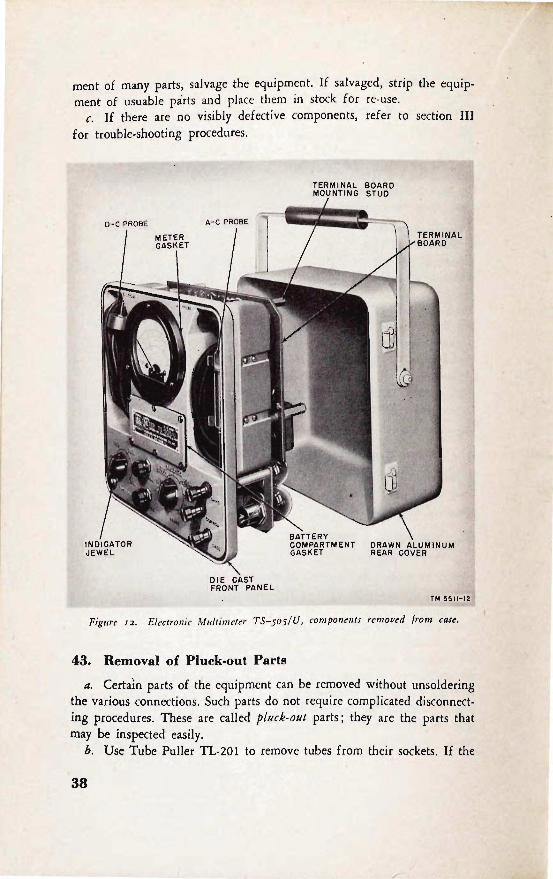
a. Make a visual inspection of the equipment when it is turned in for repair. To inspect the interior, remove the six screws on the back cover and slide the instrument out of the cover (fig. 12).
Caution: Do not lose the 0 rubber sea ling rings. Get a small box tc hold the screws and the 0 rings.
b. Analyze the extent of the necessary repair and determine whether the condition warrants repair. Two factors must be considered : whether
the replacement and· repair of major parts justifies the expense involved and the urgency of returning the equipment to service. If there is an urgent need for the equipment and a replacement is not available, the expense involved would b~ justified. If there is no urgent need and the repair involved would amount to a rebuilding operation with the replace-
37
"
ment ~f many parts, salvage the equipment. If salvaged, strip the equipment of usuable parts and place them in stock for re·use.
c. If there are no visibly defective components, refer to section III for trouble-shooting procedures.
PANEL
TERMINAL BOARD MOUNTING STUD
ERY COMPARTMENT GASKe:T
TM 5511-12
Figure 12. Electroll ic Mu/limeler TS- 505 / U, compollellts removed from case.
43. Removal of Pluck-out Parts
a. Certain parts of the equipment can be removed without unsoldering the various connections. Such parts do not require complicated disconnecting procedures. These are called plllck-out parts; they are the parts that may be inspected easily.
b. Use Tube Puller TL-20! to remove tubes from their sockets. If the
38

.t ~
TERMINAL BOARD MOUNTIN<i STUD
V
V
va
R26 R28 R30
SPARE DIODE ASS EMBLY
FUS ES
TUBE AN D TRAN SFORMER SHE LF
TERM I NAL BOARD
I
Figllre I J . Electronic MII/timeta TS- 505/ U. rear view.
Rl 3 R40 R41 R4
II
Rl2
R9
R1
R4 2
R5
R39
Rl4
C6
C4
C9
C7
V4
tubes are removed with the fingers, make sure that the tubes have cooled sufficiently, then, pull up the tube. Do not rock the tube or jiggle it in its socket if it can be extracted by a direct upward pull. Rock it genlly if it does not release easily. Jiggling a tube in its socket during removal spreads the contacts . Label each tube as soon as it is removed so that it
can be replaced later in the proper socket. · Inspect the tubes for cracks ir. glass and base and for bent and broken prongs.
44. Stripping
Many of the components of Electronic MuItimeter TS-505 / U may be
39

RI7
RI8
X6
Figure 14.
52 RANGE SWITCti
('.l. . ~~Ht-- ~~NCTION SWITCH
Electronic MlIltimeta TS-505/ U, showing tIIbc alld transformer s/ldf removed.
salvaged if it is decided that the equipment will not be repaired (figs. 13, 14, and 15).
a. The terminal board (fig. 13) can be removed by unfastening the four studs which hold it in place. Remove defective components on the t!!rminal board and place the board in stock for re-use.
b. In the event that the terminal board is broken, capacitors Cs and C9, resistors R5, RS, R1 4, and R39, and the battery holders should be salvaged if they are in good condition (fig. 15). In general, the fixed rfsistors mounted on the board are not worth salvaging because the leads would be too short. However, salvage the precision resistors R4 and R24 through R3S even though the leads are short so that some precision resistors are readily available for replacement.
c. The metal shelf containing the transformer, tubes, tube sockets, pilot light, pilot light socket, . and tube shields should be placed in stock if it is in good condition. If the transformer and tube sockets are undamaged, unfasten the shelf (fig. 14) by removing the two screws and "the two studs which hold it in place. Place the Complete unit, including cables, in stock for future use. If the metal deck is so badly bent that it cannot be salvaged, remove transformer (T1), pilot light, pilot socket, and tube sockets and place them in stock for .re-use.
d. Meter Ml , a-c probe, doc probe~ switches SI and S2, battery cover,
40

"
WATERPROOF SEAL
Figllre IS·
WASHER COMPRESSION METER NUT
Electronic Multimeter TS-soS/ U, top VIew showing tinder side of terminal board.
line cord and plug, resistors R3 and RIO, and binding post EI, E2, and E3 are all located ,on the front panel. Place these components in stock for re-use if they are in good condition. Be careful not to lose the insulators for the binding posts, the rubber gaskets, and the 0 rings.
e. The front and rear covers may be placed in stock if they are in good condition. Note that the cables in the unit have enough slack (fig. 15) so that they may be cut close to the soldered end and re-used,
45. Cleaning
If the seal has been broken, thorough cleaning of the muitirneter may be necessary to insure optimum performance by preventing corrosion, rust, and dust from damaging parts or causing arc-over or low-resistance leak-
41

age between high-voltage points and ground. Before starting on repairs, thoroughly clean the interior of the multimeter with a small brush or cloth and solvent (SD). Before placing any salvaged components in stock, clean them carefully.
Section III. TROUBLE LOCATION
46. Preliminary Procedure
a. Before attempting to locate trouble in Multimeter TS-505 j U, carefully inspect the equipment to be sure that there is no mechanical binding of switches which might cause damage to the equipment. Rotate switches S 1 and S2 to see that they are mechanically sound (no broken decks ). The detent action and the stops on switch Sl should be positive (no 360 0 rotat ion). Switch S2 should permit continuous rotation.
b. Make a visual inspection of the equipment for any signs of damage such as loose mounting screws, nuts, bolts, loose or poorly soldered connections, overheated resistors, damaged insulation, and exposed wiring which causes shorts with other wiring, terminals, or ground . The fastening nuts which hold the switches on the front panel and the binding posts should be tight.
c. Use an ohmmeter to check, if .a short circuit is indicated.
47. Trouble-shooting Procedures
a. GENERAL. The first step in servicing a defective instrument is to sectionalize the fault. Sectionalization means tracing the fault to the circuit responsible for the abnormal operation of the equipment. The second step is to localize the fault. Localization means tracing the fault tv the defective part. Many faults, such as burned-out resistors, tubes, shorted transformers, leaky capacitors, or broken wires can often be located by sight, smell, or hearing. The majority of faults, however, must be localized by checking resistance and voltage.
b. SECTIONALIZATION. Careful observation of the performance of the multimeter on the various ranges may aid in sectionalizing the trouble. Through this inspection alone, the repairman may frequently discover the trouble or determine the circuit in which the trouble exists. For example, if the operation of the multimeter is normal in OHMS, + D C, -+- 0 C, and - D C, but refuses to operate Qn A C, it is evident that the fault lies in the a-c portion of the multimeter. Obviously further attempts at sectionalizing the trouble should be made with the FUNCTION switch in the A C position. Paragraph 22 lists the normal performance of the multimeter switches.
42

c. LOCALIZATION. After the trouble has been sectionalized, the next step is to locate the specific component, or components, responsible for the improper operation of the multimeter. In the example cited in subparagraph b above, the fault might lie in a defective FUNCTION switch, a nonfunctioning a-c probe, broken a-c probe cable, or some similar portion of the equipment. Refer to the theory of operation (pars. 32 through 39), the schematic diagram (fig. 22), the trouble-shooting chart (par. 50), and the resistance and voltage charts (figs. 16 and 17) for information which will aid in the location of the source of trouble.
48. Gas Checks
a. . The proper operation and performance of the multimeter is dependent upon a set of tubes wh1ch are capable of sat1sfactory performance. Small var1at1ons 1n tube character1stics are overcame by res1stor R14, prov1ded that the tubes are not gassy. Thus, 1t 1s necessary to check for gas 1n the tubes. Tubes V3 and V4 are affected most cr1t1cally by gas w1th1n the1r envelopes.
b. Check for gas Py performing the following procedure: (1) Plug the multimeter into the power line socket (100 to 130
volts, 50 to 1,600 cps) . Turn the FUNCTION switch to +D C position and allow the multimeter to warm up for about 10 or 15 minutes.
(2) Set ZERO AD] resistor RIO to its mechanical center. Connect doc probe to COMMON binding post. Set RANGE switch to 2V position.
(3) Loosen locknut on resistor R14. ( 4) Rotate resistor R 14 until the indicator pointer is within Yz divi
sion of the zero position. Wait approximately 1 minute between settings since the action of this control is sluggish.
(5) Tighten the locknut on resistor R14; be careful not to disturb the sett1ng of the meter po1nter and the sett1ng of the control. '
(6) Set the meter needle to zero position with ZERO AD J resistor. (7) Place a short circuit across capacitor C6. The shift of the meter
needle should be less than 1 dIvIsIon. (8) If the shift is greater than 1 division, allow the multimeter to
operate for several hours. Then repeat the steps of subparagraphs 1 through 7 above. If the shift is still greater than 1 division, replace tubes V3 and V4. Check the replacements by performing the steps of subparagraphs 1 through 7 above.
49. General Precautions
W.benever the multimeter is serviced, observe the following precautions carefully:
a. Before un soldering a part, note the position of the leads. If the
43

I
part, such as a transformer, has a number of connections, tag each of the leads to it. Whenever possible, tag each lead of every part removed. The multimeter may then be accurately rewired using the schematic diagram.
b. Be careful not to damage other leads by pulling or pushing them
out of the way. c. Do not allow drops of solder to fall into the multimeter, since they
may cause short circuits. d. A carelessly soldered connection may create a new fault. It is very
important to make well-soldered joints because a poorly soldered joint is one of the most difficult faults to find. Use alcohol and a small brush to remove excess rosin from joints.
e. After the multimeter has been repaired, go over all new parts with moistureproof and fungi proof varnish.
f. A systematic procedure should be developed in checking the multimeter. Follow the calibration procedures in paragraphs 51 and 52, using the trouble-shooting chart (par. 50), and make the necessary repairs until the meter calibrates properly.
50. Trouble-8hooting Chart
a. GENERAL. The following chart is supplied as an aid in locating trouble in the multimeter. The chart lists the symptoms which the repairmen may observe either visually or audibly, while making a few simple tests. The chart also indicates haUl to localize trouble quickly to a particular stage or circuit. Once the trouble has been localized to a stage or circuit, a tube check and voltage and resistance measurements of this stage or circuit should ordinarily be sufficient to isolate the defective part. Normal resistance and voltage measurements are given in figures 16 and 17. Capacitor and resistor color codes are shown in figures 18 and 19.
44

.... ~
h. TROUBLE-SHOOTING CHART FOR MULTIMETER TS-505;U.
Switch position SI S2
1. Any except OFF.
Any.
Abnormal indication
Pilot light does not go on; no movement of meter; line voltage normal.
Probabl. fault
a. A-c line plug is not properly inserted in socket.
b. Burned-out fuse Fl, F2. .. Defective a-c line cord. d. Defective snap switch, 51,
section 7. e. Defective transformer, Tl. f. Short across filament wind-
ing of transformer Tl. g . Pilot lamp burned out.
R.medial action
a. Insert correctly.
b. Replace defective fuse. c. Replace or repair line cord . d. Replace or. repair switch.
e. Replace transformer. f. Locate and remove short.
I g . Replace E 13.

--~ b. TROUBLE-SHOOTING CHART FOR MULTIMETER TS-505/U (contd)
Switch position 51 52
3. +D C. 2V
4. +D C. a. IOOOV.
b. 400V.
c. 200V.
Abnormal indication
Meter pointer is near zero but cannot be adjusted to zero with RIO.
Meter drifts until off scale.
Probable fault Remedial action
g. No voltage at cathode of g. Check VB and TI; replace VB. if defective.
a. RI4 defective. a. Replace RI4.
b. RIO defective. b. Replace RIO. e. Line voltage too high or too c. Apply correct line voltage.
low. d. Defective tube, V3 through I d. Replace defective tube.
V7. e. R9, RII, open or shorted. e. Replace defective resistor.
a. R24 open (grid of V3 to COMMON binding post should measure 75,000 ohms) ; dirty or open contact on S2.
b. Same probable fault as sub· paragraph a above.
e. R22 open (grid of V3 to COMMON binding post should measure 150,000 ohms) ; dirty or open contact on S2.
a. Replace R24; clean contact.
b. Same remedy a~ subparagraph a above.
c. Replace R22; clean contact.

If6 "'-l
SI Switch position
S2
d. lOOV.
e. 40V.
/. 20V.
g. lOY.
h. 4V.
Abnormal indication
d.
e.
t·
g.
h.
Probable fault Remedial action
R21 open (grid of V3 to d. Replace R21 ; clean contact. COMMON binding post should measure 300,000 ohms) ; dirty or open con· tact on 52 .
R20 open (grid of V3 to e. Replace R20; clean contact. COMMON binding post should measure 750,000 ohms) ; dirty or open con-tact on 52 .
Rl9 open (grid of V3 to t· Replace R19; clean contact. COMMON binding post should measure 1.5 meg-ohms) ; dirty or open con-tact on 52.
RIB open (grid of V3 to g. Replace RIB; clean contact. COMMON binding post should measure 3.0 meg-ohms) ; dirty or open con-tact on 52.
Rl6 open (grid of V3 to h. Replace R 16; clean contact. COMMON binding post should measure 7.5 meg-ohms) ; dirty or open con-tact on 52.
-

t b. TROU BLE-SHOOTING CHART FOR MULTIMETER T S-505/U (contd)
Switch position Abnormal indication Probable fault Remedial action I
SI $2 I
i. 2V. I. R15 open (grid of V3 to I. Replace R15; clean contact. COMMON binding post should measure 15 meg-ohms) ; dirty or open con· tact on S2.
j
~ . +D C. 2V. Application of 2V ±1% to a. R4 has the wrong value. a. Replace R4. I
meter results in error greater I than 4%.
b. R12 open. h. Replace R12 .
". Resistors R1 5 through R24 ". Find wrong resistor or reo are not within 1 % of cor- sistors and replace. reet value.
d. Meter (M1) error greate« d. Replace meter. than ± 2%.
6. + D c. 400V. Apply approximately 400 v to R23 short-circuited. Locate short circuit and' repair. d·c probe and then turn switch S2 to 1000V position. Meter does not read 400 von 1000V range.
7. ±D C. See item 4 above. Meter drifts until off scale. See item 4 above. See item 4 above.
8. ±D C. Any. Meter pointer not at midscale. a. R8 set incorrectly. a. Refer to paragraph 52g, h, i, and j .
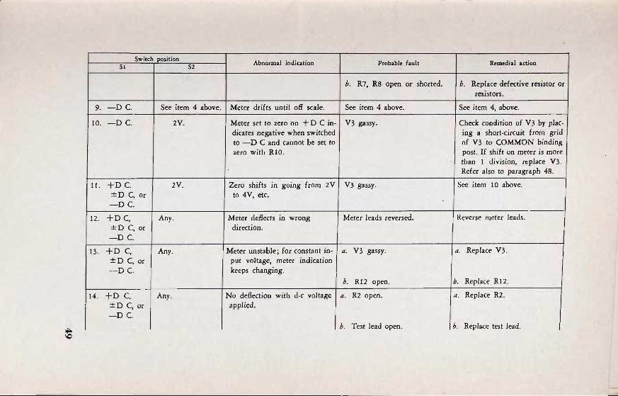
Switch position Abnormal indication Probable fault Remedial action
SI S2
h. R7, R8 open or shorted. h. Replace defective resistor or resistors.
9. -OC See item 4 above. Meter drifts until off scale. See item 4 above. See item 4, above.
10. -OC 2V. Meter set to zero on + 0 C in· V3 gassy. Check condition of V3 by plac. dicates negative when switched ing a short-circuit from grid to -0 C and cannot be set to of V3 to COMMON binding zero with RIO. post. If shift on meter is more
than 1 division, replace V3 . Refer also to paragraph 48.
11. +0 C 2V. Zero shifts in going from 2V V3 gassy. See item 10 above. ±o C, or to 4V, etc. -OC
12. +0 c, Any. Meter deflects in wrong Meter leads reversed. Reverse meter leads. ±O C, or direction. -0 C
13 . +0 C, Any. Meter unstable; for constant in· a. V3 gassy. a. Replace V3. ±O C, or put voltage, meter indication -OC keeps changing.
h. R12 open. h. Replace R12 .
14. +0 C. Any. No deflection with d·c voltage a. R2 open. a. Replace R2. ±O C, or applied.
•
-0 C . h. Test lead open. h. Replace test lead.
~

~ b. TROUBLE-SHOOTING CHART FOR MULTIMETER TS-505jU (cQntd)
I Switch position Abnormal indication
51 52 Probable fault Remedial action
15. +D C, Any. Application of low frequency a. C4 open. a. Replace C4. ±D C, or (approx 30 cps) to d-c pro~ - D C. causes meter pomter to vibrate. b. C6 open. b. Replace C6.
16. OHMS. Any. Batteries in place, no deflection. Short between OHMS and Locate and remove short. COMMON binding posts.
17. OHMS. Any. Batteries in place, no deflection. Batteries improperly inserted Insert properly, observings , (positive or negative termi· polarity.
nals of battery connected to· gether.)
18. OHMS. Any. Meter pointer drifts upscale. No batteries. Insert batterie~. observing polarity.
19. OHMS. Any. Meter pointer deflects against Batteries inserted with polarity Reverse batteries, observing left hand stop. reversed. polarity.
20. OHMS. a. RXl. Meter drifts upscale. a. R32 open. a. Replace R32. b. RXIO b. R33 open. b. Replace R33. c. RXIOO. c. R34 open. c. Replace R34. d. RXIOOO d. R35 open. d. Replace R35. e. RXI0K. e. R36 open. e. Replace R36. f. RXIOOK f. B37 open. f· Replace R37. g. RXIMEG. g. R38 open. g. Replace R38.

CIl ~
21.
22.
23.
24.
25.
26.
SI
OHMS.
OHMS.
AC
AC
AC
AC
Switch position
- Any.
Any.
2V.
Any.
Any.
Any.
S2 Abnormal indication
Full clockwise rotation of OHM AD] does not bring meter pointer to infinity.
Full counterclockwise rotation of OHM AD] does not bring meter pointer below infinity.
Meter cannot be set to zero with RIO or R39 (no input voltage to a-c probe).
No meter deflection with ac applied to a-c probe.
Meter deflects with d-c voltage applied to a-c probe.
R5 will not adjust meter for calibrating.
Probable fault Remedial action
a. Low battery voltage. a. Replace batteries.
h. R3 defective. h. Replace R3 .
a. Wrong batteries. a. Replace with BA-30.
h. R3 defective. h. Replace R3. c. See item 20. c. See item 20.
a. R 1 open or shorted, or of a. Replace with spare diode incorrect value. asseIRbly.
h. R25 through R31 open or h. Find incorrect resistor and shorted, or of incorrect replace. value.
a. Cl open. a. Replace with a-c probe shell.
h. VI burned out. h. Replace with spare diode assembly.
c. Defective ·a-c probe cable. c. Replace a-c probe cable.
CI defective. Replace a-c probe shell.
R5 open or shorted. Replace R5.

-~ h. TROUBLE-SHOOTING CHART FOR MULTlMETER TS-505/U (contd)
Switch position Abnormal indication Probable fault Remedial action 51 52
27. AC. Any. Meter deflects positive with no a. V2 inoperative. a. Replace with V2. input voltage; rotation of R39 has no effect.
b. R25 through R3I open or b. Locate defective resistor or shorted, or of incorrect resistors and replace. value.
Co R39 defective. c. Replace R39.
28. AC. Any. Meter deflects negative with no a. VI inoperative. a. Replace with spare diode input voltage; rotation of R39 assembly. has no effect.
b. Filament lead to VI open. b. Repair a-c probe cable. c. RI open. c. Replace with spare diode
assembly. d. R39 defective. d. Replace R39.
29. AC. Any. Meter deflects positive with no a. Shields on a-c probe cable a. Replace a-c probe cable. input voltag~; indication on defective. meter varies as hand is brought near case or a-c probe.
b. Pick-up on case. b. Connect CASE to a good ground.
i 30. AC. Any. Application of low-frequency a-c C4 open. Replace C4. voltage gives lower deflection t.hen high-frequency voltage_
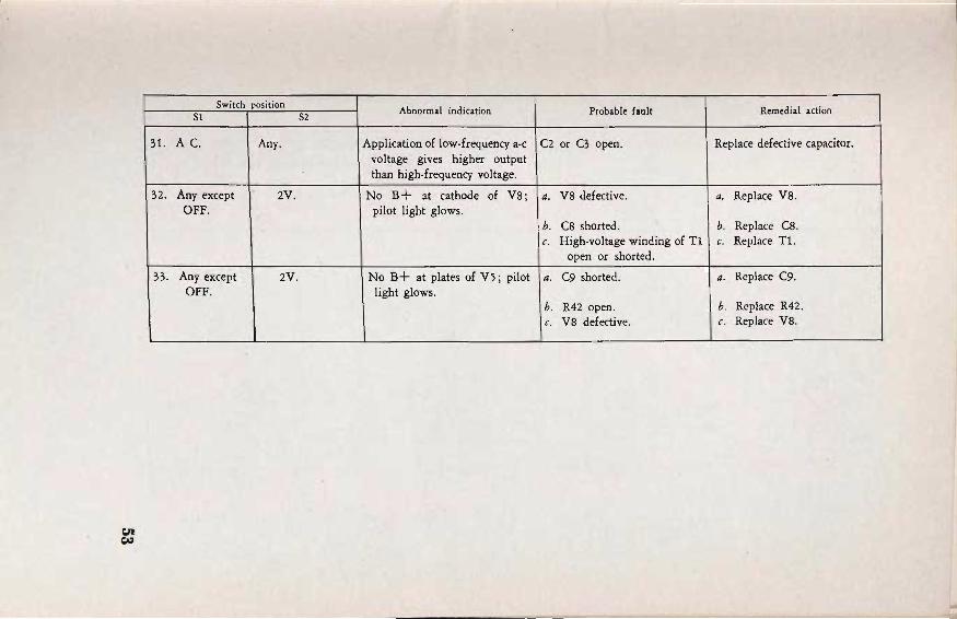
c:n ~
Switch position S1
31. A C. Any.
32. Any except 2V. OFF.
33. Any except 2V. OFF.
S2 Abnormal indication
Application of low· frequency a-c voltage gives higher output than high-frequency voltage.
No B+ at cathode of V8; pilot light glows.
No B+ at plates of V5 ; pilot light glows.
- -
Probable fault Remedial action
C2 or C3 open. Replace defective capacitor.
a. V8 defective. a. Replace VB.
h. CS shorted. b. Replace CS. L High-voltage winding of Tl c. Replace T1.
open or shorted.
a. C9 shorted. a. Replace C9.
h. R42 open. h. Replace R42. c. V8 defective. c. Replace V8.

• II
~
V7 0 VB NE-32 6X4
,,~ -@oo '~oo o 30. 12 K <Xl 21 7 <Xl n 3 22
12 K 600 r@ .... '"
V6 V5
~·U' NE- 32 12 AT1
00 -@.' 0 <Xl e 0 <Xl 7 0
<Xl <Xl
<Xl .2
<Xl
0
NOTES I. ALL SOCKETS VIEWED FROM BOTTOM 2. ALL POTENTIOMETE~S AT MECHANICAL CENTER 3 . RANGE SWITCH AT 2V POSITION; FUNCTION SWITCH
AT +DC POSITION. 4.MEASUREMENTS MADE BETWEEN DESIGNATED POINTS
AND COMMON BINDING POST 5. UNLESS OTHERWISE SPECIFIED, RESISTORS ARE IN OHMS.
TI
V2 6AL5 ' .. ~~oo 5 •
.2 4~7 3MEG o 32.
3MEG 1,450
V3 <Xl 6AU6 <Xl
'.~m o 3 21
93K 15 MEG
Figure 16. Eleclronic Multimeter TS-505/U, lube sockel resi.rtallce diagram.
0
/ / / / \or-O
V4 <Xl 6AU6 <Xl
"'~'" o 3 2 I
93K 1,450
0
TM 55/1-16

.~ :);,JJ
~
..._----------.,.--------------------.,---------------'1 -S.3Y AC
V7 ' KE-"'32 0 0-E&-,,,
V6 HE-32
V8 "6'X4
' 25OV 'All '
W5 ~.AC·· 12 AT7 ~165V
58V
,I
m-E&-o 56
58V .6.3V .AC ,! ______ -J.!
o HOTES
I. ALL SOCKETS 'VIEWED FRO .. 80TTOM 2.ALL POTE-NTlO"E'TEIfS AT ."E'CHA·HIC'AL 'llEN'fE'R 3 .ALL '''E~URE''ENTS .. ADE WITH 20, OOO-OH"S-PER-VOLI ' If£'TElI 4. ALL .. EASURE .. ENTS ARE DC EXCEPT AS OTHER-WISE NOTED 5. RANGE SWITCH AT 2 V POSITION', FUNCTION SWITCH 'AT +llC "PU SI'I'ION
Y2 -6~'5
o
;t.6:3.V I DO:ri .~ ,V ~o
D 3 2 I
6:3V'A'C i
~5V 0
V-3 6'AU,6
S'6Y~
S.2V:A'C
U
v :S8'V '~S6!O'
~.-2lI AI)
o
"~'V
I.25V
~O
<0
OV
6 .... EASURE .. ENTS .. ADE ,sE·TWE£N DESIGNATED POINTS .AND COII .. ON ;BINDING ·P'OS.T 7. LINE VOL1"AC;-E 115V AC
,T" -s51t- ~7
Frgure 'n. 'Electro"ic Mufti-meter ·rrs·'YOY/'[], 'tube ', oc'kel :vdft4gf! ,iJiagram.

=
=~= "Vly~'~;"'G
to}"G,,,,.Gt,111 .st ' ,ClU!ttS
'''OfoIT
=~= ~~.
CAPACITOR COLOR CODES
CJ
4-00T COLOR CODING I~ '1OG.'
B
CJ
111["" 5 - 00T COLOR COOING
r-----------~--~C.r-------------------_,
=
... oo -... ...... ''''Oo ..... .... 'I'OltT '114'" ."'fIt ..... IILY[ II 1110 ""-0tII
D
IN .. 1III1C,4- ,,1otO C:U"IIIIC-OttLlC11II1C ,
~
'00 ," ... ~...... 000
~o: ""DO .00
RMA COLOR CODE FOR TUBULAR CERAMIC-DIELECTRIC CAPACITORS
, ~
'00 .... -,.
000 .... .00 DO
' 00 100 >00
:: ... :gg 000 ,.-tOO
JAN 6-00T COLOR CODES FOR:
F MICA-DIELECTRIC CAPACITORS +
G
CERAMIC-DIELECTRIC CAPAciTORS **
=
=
H NOTES
III 1M[ "lY[II 001 'Df.Io"t'(5 h", """h~I~10 ~rsU~~O:f~;;.o ~.ClU HI JaN fl.t
I TMt .LACIt ClOt IDCIII""[' 1101' ,,",U" tNQ
~'=T~:.o l~"ClU St[ J4,. l1'1>(.
'UIltolt.D .'TI, COOt _Y1: 1t"' ,1<fQ 01 '-00 (""[111 011 001 cOOt ,.... ~D'OIt .'to IU,I~·L[
!t401k.-ltt.OI e.a
Figure 18. Capacitor color codes.
56
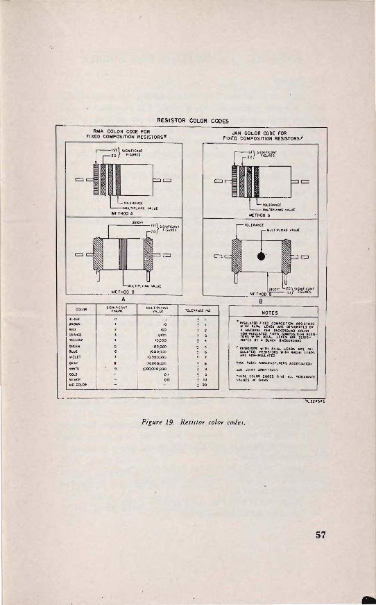
=
RESISTOR COLOR CODES
RMA COLOR CODE FOR JAN COLOR CODE FOR FIXED COMPOSITION RESISTORS. FIXED COMPOSITION RESISTORSf
j
TOL[IIA ... C[
MULtiPLYING VAlU[
I)IETHOD A
t800T) IST}5 "
=
IGNlnCANT r'GuAts
=c
r-15f} SIGNIFICAN T 20 "GuAU
pp
1-..'0I"(A4,,,(;(
""'---- IoIUltIPL't'ING VALU[
Jr.IETHOO A
r-TOL["ANC(
rIolUlTIPL'f'IHG VAtuE
= c~ p ~
= =c .t· p=
COlOA
BLA'K
BROWN
REO
OR''''' VELLOW
OF/UN
BLUE
VIOL(t
CiAAY
WHI T[
00t.0 SILV!R
NO COLOR
'-MULT ip!'flNG VALV
METHOD e A
SIGNIFI'ANT fIGuR(
IoIULflPL'!' ING VALUe
'0
'00 ',000
'0,000
100,000
',000,000 10,000,000
100,000,000
IPOO,OOO,ooo 0' 00'
! • ! , ! • ! T .. ! , t , !" 10
'0
~0}5'j""'''"T METHOO 1ST IGUAtS
B
NOTES
" IHSlILATEO nato COMPO$ITlOH R[SISTORS WITH .... '''L lUDS ARC OlSICiNlT[O 1'1' " HATUlt"l TAN 8ACII(;"OONO COLOR NOH-INSULAT(() fll([O COUIflOSITION III[SISTOilS W,TH AXIAL lUDS .IIE DesIGNATeo 111' " 8I..A," eACKGROUND
, "[SISTORS WITH AXIAL lUDS UIE IHSULAT[D It(SISTOlilS WITH A~I 'L LCAOS ARE NOH-INSuLAT(O
A .. A RAI)IO MANUrACTURHIS ASSOCIATION
JAN JOI NT A""'V - NAVV
THEs[ COlOR C.OOES GivE ALL RESISTANCE VALUES 1111 OHMS
Pigure 19. ResiJlor color codes.
57

Q • IV CALIBRATION PROCEDURES ~ecfloll •
51. General
Electronic Multimeter TS-505f(J is calibrated during manufacture. a. ~fter calibration, resistors R3, R5, lU8, llnd R39 are locked in p~ac~. Recalibration Is not required unless the tubes are replaced, or It IS definitely known that adjustments must be made. For example, recalibration is required if operating the ZERO ADJ control does not bring the meter pointer to the zero position on the meter despite the fact that control is available ,
b.. The calibration controls arQ illustrated in figures 13, 14, and 15.
52. Settillg Zero Control8
a. Plug the multi meter into the power line socket (100 to 130 volts, 50 to 1 ,600 cp~). Turn the FUNCTION switch to + D C and allow the rnultimeter to warm up for about 10 to 15 minutes.
b. Set ZERO ADJ resistor RIO to its mechanical center. Connect the d-c probe to the COMMON binding post. Operate the RANGE switch to the 2V position.
c, Loosen the locknut on resistor R14. d, Rotate resistor R14 until the meter pointer is within V2 division
of the zero position. Wait approximately 1 minute between the settings since' the action of this control is sluggish.
e. Tighten the locknut on resistor R14. Be careful not to disturb the setting of the control.
f, Set the meter pointer to the zero position by operating the ZERO ADJ resistor.
g. Operate the FUNCTION switch to the -+- 0 C position. h. Loosen the locknut on resistor R8. I. Rotate resistor R8 until the meter pointer is at midscale. j. Tighten the locknut on resistor R8. Be careful not to disturb the
setting of the control. k. Operate the FUNCTION switch to the - D C position. The meter
pointer hould be within 1 division of zero. If the meter pointer is outide the r~ge of control by the ZERO ADJ resistor, refer to paragraph 48
{or correcttve procedure. I. Operate the FUNCTION switch to the OHMS position. The meter
pointer hould read upscale. Adjust the meter pointer to 00 by operating the OHM AD] control R3.
m. Operate the FUNCTION switch to the A C position. 11. Loosen the locknut on resistor R39.
58

o. Adjust resistot RI8 until the meter pOlhter is in the zero position. p. 'tighten the locknut on resistor 1t39. Be careful not to dlsttlro the
setting of the control. 1. Operate the FUNctION switth to the D C posititln. Operate the
RANGE switch to the 2V position. r. Apply 2 volts -1- I percent to the d-c probe. The meter pointet
should read within 4 percent. If the ertor is greater than this, check the resistance of resistors R4, and Rl5 through R24. Check the accuracy df meter MI against a standard. •
s. Repeat the step in subparagraph r above for each range with appropriate voltages.
t. Operate the FUNCTION switch to the OHMS position. Check the accuracy of the ohms calibration by using standard resistors known to be accurate within 1 percent. It the teading on the meter is not within 4 percent of full scale (total scale arc), check resistors R32 through R38.
u. Operate the FUNCTION switch to the A C position. Operate the RANGE switch to the 10V position.
v. Loosen the locknut on resistor R5. w. Apply 10 volts ~ 1 percent at 400 cps, to the ao..c probe.
The 400 cps must have--less than .5 percent distortion. x. Rotate resistor R5 until the meter pointer reads full scale. y. Repeat the step in subparagraph w above, on the other ranges
with appropriate voltages. The teadings should be within ±6 percent. z. Tighten the locknut on resistor R5 . Be carelul not to disturb the
setting of ,the control.
53. Replacement of A-c Probe Assembly a. Because of the mechanical difficulties 'and special techniques needed
to replace the tube in the a-c probe (fig. 20) repair of this component is not recommended. Instead, if capacitor CI is defective, replace the a-c probe shell. If diode VI or resistor RI is defective, replace with a spare diode assembly.
b. To replace the a-c probe shell: (1) With one hand, grasp the diode assembly retaining screw (fig. 20)
to prevent it from turning; with the other hand, loosen the waterproof sealing nut.
Caution: Do not use tools on these parts. The fingers of your hand should be sufficient.
(2) Loosen the diode assembly retaining screw. The a-c probe shell wi ll separate from the rest of the assembly.
(3) Replace the defective a-c probe shell with a good unit. (4) Tighten the diode assembly 'retaining screw.
59
(5) Tighten the waterproof sealing nut. ' . Caution: Do not attempt to disassemble the a-c probe without first
loosening the waterproof sealing nut. Failure to do this may result in a broken tube. In assembling the a-c probe, the waterproof sealing nut should be tightened last.
c. To replace the spare diode assembly: (1) With one hand, grasp the diode assembly retammg screw to
prevent it from turning; with the other hand, loosen the waterproof sealing nut.
(2) Loosen the diode assembly retaining screw. The a-c probe shell will separate from the rest of the assembly.
(3) Slip the waterproof sealing nut, washer, waterproof seal, diode assembly retaining screw, and insulator over the a-c probe cable (fig. 21)
to permit access to the tube base. (4) Carefully unsolder the cable from the tube base. Tag the cable
leads to permit identification when resoldering. (5) Remove a spare diode assembly from the rear of the multimeter
and carefully solder the leads from the cable to the spare diode assembly. (6) Replace . the a-c probe shell and tighten the diode assembly
retaining screw. (7) Tighten the waterproof sealing nut. Caution: Observe the cautions in subparagraph b above. d. To replace the a-c probe cable; (1) Repeat the steps in subparagr.aph b (1) through (4) above at the
a-c probe end of the cable. Put the waterproof sealing nut, washer, waterproof seal, diode assembly retaining screw, and insulator on the new cable in the order shown in figure 21.
(2) Repeat the steps in subparagraph b( 6) and (7) above. (3) Remove the' sealing nut, washer, and . waterproof seal at the multi
meter end of the cable. An open-end wrench may be used on the sealing nut.
(4) Unsolder the cable leads from the terminal board. Tag the cable leads to permit identification when resoldering.
(5) Put the sealing nut, washer, and waterproof seal (in the order named) on the new cable . .
(6) Solder the new cable to the terminal board. (7) Tighten the sealing nut with an open-end wrench. Note. Order replacements immediately for any parts of the I-C probe which are
replaced.
60

MOLDED POLYSTYRENE
~~:fClf8~~AININ G LL
DIODE ASSEMBLY RETAINING SCREW
WATERPROOF PROBE SEALING NUT CABLE
Figlll'~ 20. A-c {7rob~.
Section V. REFINISHING 54. Appearance
d. GENERAL. Check all metal surfaces for appearance and condition of the finish. From a protective and durability standpoint, the finish should show no decided wear and should not be chipped or scratched to show any bare metal. Refinish surfaces where the finish has been removed completely or worn th rough or where it has been removed as a result of sanding or scratch brushing. Retouch such surfaces if the bare spots are restricted to small areas, but if the bare or damaged spots cover large areas, completely refinish the en.tire part. Discolored, spotted, stained, or faded surfaces are permissible provided the original finish is intact.
b. FINISHING PROCEDURES. After sanding or scratch brushing, retouch affected surfaces to match the original finish . Apply one coat of clear lacquer to parts having a bright metal finish. Apply one coat of enamel to painted surfaces. Do not apply lacquer to surfaces which might affect the mechanical or electrical function of the equipment.
55. Refinishing After Repair
After repairing Electronic Mu ltimeter TS-505 / U, repaint any unprotected surfaces. If any components in the multimeter have been replaced, repaired, or resoldered, moistureproof and fungi proof the component with varnish. After the varn ish has dried, p lace the unit in the back cover and tighten with the holding screw. Be careful not to strip the threads.
61

I I (I· - - - -I .1.
a-. ~
MULTIPLIER A-C PROBE SHELL
DIODE ASSEMBLY RETAIN ING SCREW
Figure 21. Exploded view 01 a-c probe.
WATERPROOF SEAL
. WATERPROOF SEALING NUT
HI 5511-19

CHAPTER 5
SHIPMENT AND LIMITED STORAGE AND DEMOLITION TO PREVENT ENEMY USE
Section I. SHIPMENT AND STORAGE
Note. The circumstances involved in shipment and storage vary, and therefore no definite procedure for repacking can be given. The following instructions are recommended as a guide for preparing Electronic Multimeter TS-5051U for transportation and storage.
56. Removal from Service
a. Disconnect the multimeter from the power supply. h. Place the probes into' their respective compartments. Place the
power cord into its compartment. c. See that all tubes are seated firmly in their sockets. d. Fasten the covers in place.
57. Repacking for Shipment or Limited Storage
a. The exact procedure in repacking for shipment or limited storage depends on the material available and the conditions under which the equipment is to be shipped or stored. Refer to paragraph 9b and figure 4, and follow the instructions in reverse order.
b. Whenever possible, place a dehydrating agent such as silica gel inside the equipment. Protect the equipment with a waterproof pa~er barrier. Seal the seams of the paper barrier with a waterproof sealmg compound or tape. Pack the protected equipment in a padded fiberboard box.
Section II. DEMOLITION TO PREVENT ENEMY USE
58. Methods of Demolition a. SMASH. Use sledges, axes, handaxes, pickaxes, 'hammers, crowbars,
heavy tools.
63 •

b. CUT. Use axes, handaxes, machetes. c. BURN. Use gasoline, kerosene, oil, flame throwers, incendiary
grenades. d. EXPLODE. Use firearms, grenades, 1NT. e. DISPOSE . Bury in slit trenches, fox holes, other holes; scatter. Do
not throw in streams; the multimeter is waterproof and will float. Note. Use anything immediately available for destruction oj this
equipment.
59. Destruction of Components
When ordered by your commander, destroy all equipment to prevent its being used or salvaged by the enemy.
a. Smash (par. S8a) the meter, tubes, resistors, switches, and capacitors. b. Cut (par. 58b) cords and wiring. c. Burn (par. 58c) cords, resistors, capacitors, coils, wiring, office
recorcis, and technical manual. d. Bend the case, cover, and panel. e. Bury or scatter (par. S8e) all remaining parts of the equipment.
DESTROY EVERYTIDNG
64

APPENDIX I
REFERENCES
Note. For availability of items listed, check SR 310-20-3 for field manuals, training circulars, training aids, Army training programs, JANAP's, Tables of Organization and Equipments (T IO&E), Tables of Allowances (T/ A), and Tables of Basic Allowances (T/BA) . Check SR 310-20-4 for technical manuals, technical bulletins, s'lpply bulletins, modification work orders, and Changes. Check Departfllent of the Army Catalog SIG 1 for Signal Corps supply catalo.g pamphlets.
1. Army Regulations
ABo 380-5
2. Supply Publications
SB 11.6
sa 11-47
SB 11-76
Safeguarding Military Information.
Dry Battery Supply Data.
Preparation and Submission of Requisitions foc Signal Corps Supplies.
Signal Corps Kit and Materials for Moisture and Fungi-Resistant Treatment.
3. Technical ManuQls Qn Test Equipment
TM U-3Q3 TM 11-321
TM 11-472
TM 11-261? TM 11-2626 TM 11-2627
Test Sets I-56-C, -D, -H, and -J. Technical Manual for Test Set
1-,6-E. Repflir and Calibration of Electrical
Measuring Instruments. Voltohmmetcr 1-166, Test Unit 1-176. Tube Tester 1-177.
4. Painting, Preserving, and Lubdcation
TB SIG 13
TM 9-2851
MoistureproQfing find Fungiproofing Signal CQrps Equipment.
Painting Instructions for Field Use.
65

Decontamination 5. D econtamination. TM 3-220
6. Demolition Explosives and Demolitions. FM 5-25
k . 17 and Packing Instructions
7. Pac agIne NS VY PACKAGING SPEClFlCATIO . .
a. JOINT ARMy-NA Desiccants, AChvated. JAN-D-169 General Specification . JAN-P-100 Boxes; Wood, N ailed. JAN-P-I06A Preservation , Methods of. JAN-P-1l6 Barrier-Materials, Waterproof, JAN-P-125 Flexible.
JAN-P-13 1
b. U. S. ARMY SPECIFICATION.
100-2E
100-14A
Barrier Material; Moisture-Vaporproof, Flexible.
Marking Shipments by Contractors (and Signal Corps Supplement thereto) .
Army-N avy General Specification for Packaging and Packing for Overseas Shipment.
c. SIGNAL CORPS INSTRUCTIONS. 720-7 Standard Pack. 726-15 Interior Marking.
8. Other Publications
SR 310-20-3
SR 310-20-4
66
Index of Army Tr~ining Publications (Field Manua s, T raining Circulars, Firing Tables and Charts, Army Training Programs, Mobilization Training P rograms, Graphic Training Aids, Joint-Army-Navy-Air Force Publications, and Combined Communications Board Publication) .
Index of T echnical Manuals, Technical Regulations, Technical Bulletins, Supply Bulletins, Lubrication Orders, Modification Work Orders,

TB SIG 123
TM 11-490 TM 11-453 TM 11-455 TM 11-660 TM 11-4000
TM 38-650
Tables of Organization and Equipment, Reduction Tables, Tables of Allowances, Tables of Organization, Tables of Equipment, -and Tables of Basic Allowances.
Preventive Maintenance Practices for Ground Signal Equipment.
Electrical Fundamentals. Shop Work. Radio Fundamentals. Introduction to Electronics. Trouble Shooting and Repair of
Radio Equipment. Basic Maintenance Manual.
APPENDIX II
IDENTIFICATION TABLE OF PARTS FOR
ELECTRONIC MULTIMETER TS.505/U
Note. The fact that a part is listed in this table is not sufficient basis for requisitioning the item. Requisitions must cIte :tn authorized basis, such as T/O&E, T/ A, SIG 6, SIG 7&8, SIG 7-8-10, SIG 10, list of allowances of expendable material, or anot~er authorized supply basis. The Department of the Army Supply Catalog applicable to the equipment covered in this instruction book is SIG 7&8-TS-~05lU. For an index of available catalogs in the Signal portion of the Department of the Army Supply Catalog, see the latest issue of SIG I, Introduction and Index.
67

~ Identification Table of Parts for Electronic MuJtimeter TS·505jU (contd)
Rei symbol
BA-l, BA-2
Cl C2, C3
C4
O,C6
C7
C8, C9
ClO
Name of part and description
ELECTRONIC MULTIMETER TS-505 IU: electronic type, ID vac, 50 to 1600 cyc; 0 to 1000 v dc in 9 steps, 0 to 500 v dc wi 0 ctr in 9 steps, 0 to 200 v ac in 7 steps, 0 to 1000 meg in 7 steps.
BATTERY: JAN type BA-30; IY] v ; specification JAN B18A.
CABLE, power : 2 # If! A WG stranded condo
CABLE, power: a-c probe cable ; 3 # 18 A WG stranded copper cond; 16 # 30 A WG strands; 300 v working; Specialty Packing part No. 123E-1-F.
CAPACITOR, fixed; ceramic ; 6000 uuf ; part of ac probe assembly .
CAPACITOR, fixed : ceramic ; 1000 uuf +100% -0; 200 vdcw; Specialty Packing part No . 123E-1-5.
CAPACITOR, fixed : paper ; .01 uf ±20%; 1000 vdcw; JAN type No. CN43AI03M.
CAPACITOR, fixed: paper; .01 uf ± 20%; 400 vdcw; JAN type No. CN30E103M.
CAPACITOR, fixed: paper; .02 uf ± 20%; 200 vdcw; JAN type No. CN22E203M.
CAPACITOR, fixed: paper; 2 uf ±1O%; 600 vdcw; JAN type No. CPBBIEF205K.
CAPACITOR, fixed: ceramic; .0001 uf ±20%; 500 vdcw; Erie part No. GP2-331-100 ± 10. .
Function of part
Measures a-c and doc voltages and resistances of electronic equipment over relatively wide ranges.
Supplies voltage to ohmmeter section.
Connects multimeter to a-c power source.
Connects test prod assembly to multimeter.
Input coupling capacitor.
Bypass rf in a-c probe.
Bypasses ac.
Same as C4 .
Same as C4.
Filter power supply.
High frequency bypass.
Signal Corps stock No.
3F4325-505
3A30
1 B818.14
IB3018-3.8
30AI-287
30A10-450
30AI0-437
3DA20-246
30B2-143
309100-2119
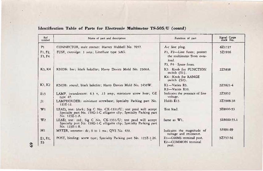
Q'\ \C
Identification Tahle of Parts for Electronic MuItimeter TS·505/U (contd) .
Ref symbol
PI
Fl, F2, F3,F4
K3,K4
Kl, K2
E13
}l
WI
W2
Ml
El, E2, I E3
Name of part and description
CONNECTOR, male contact: Harvey Hubbell No. 7057.
FUSE, cartridge: 1 amp; Littelfuse type 3AG.
KNOB: bar; black bakelite; Harry Davies Mold No. 2300A.
KNOB: round; black bakelite; Harry Davies Mold No. 1450W.
LAMP, incandescent: 6.3 v, .15 amp; miniature screw base; GE type 47.
LAMPHOLDER: miniature screwbase; Specialty Packing part No. 123E·12.
LEAD, test: black; Sig C No. CX-1331/U; test prod will accept Specialty part No. 150G·1-C alligator clip; Specialty Packing part No. 123E-I-A.
LEAD, test: red; Sig C · No. CX-1331/U; test prod will accept Specialty put No. 150G-1·C alligator clip; Specialty Packing part No. 123E-1-B.
METER, ammeter: dc; 0 to 1 rna ; QVS No. 450.
POST, binding: screw type; Specialty Packing part No. 123E-1-26.
Function of part
A-c line plug.
F1, F2-Line fuses; protect the multimeter 'from overload.
F3. F4-Spare fuses.
K3-Knob for FUNCTION switch (SI).
K4-Knob for RANGE switch (S2).
KI-Varies R3. K2-Varies RlO. Indicates the presence of line
voltage. Holds E13.
Test lead.
Same as Wi.
Indicates the magnitude of voltage and resistance.
EI-OHMS terminal post. E2-COMMON terminal
post.
Signal Corps stock No.
6Z1727
3Z1926
2Z5838
2Z5821-4
2Z5952
2Z59!l!l-3!l
3EBOOO-53
3EBOOO·53.1
3FB91-B9
3Z737-56

------------------------------~------------------------------~--------------------------
~ Identification Table of Parts for Electronic Multimeter TS·505jU (contd)
Ref symbol
E4
E5
Rl
R2
R3
R4
R5
R7
R8
R9, Rll
Nam~ of part and d~scription
PROD, test: red; plastic body; contains R2; Specialty Packing part
No. 123E-I-2. PROD ASSEMBLY, test: ac probe; consists of ac probe shell, diode
assembly. waterproof sealing nut, washer, waterproof seal, diode assembly retaining screw, and insulator.
RESISTOR, fixed : composition 15 meg ±5%; Y2 w; JAN type No. RC20BFI56J; part of a-c probe assembly.
RESISTOR, fixed: composition; 5 meg ± '12%; '12 w; Wilkor
Products type CP Y2. RESISTOR, variable: composition; 2500 ± 20%; 2 w; Specialty
Packing part No. 123E-I-66. RESISTOR, fixed: composition; 1450 ohms ±Y2%; '12 w; Wilkor
Products type CPS Y2. RESISTOR, variable: composition; 2500 ohms ± 20%"; 2 w; Specialty
Packing part No. 123E-I-67.
RESISTOR, fixed: composition; 100,000 ohms ± 10%; I w; JAN type No. RC30BFl04K.
RESISTOR, variable: composition; 50,000 ohms ± 20%; 2 w; Specialty Packing part No. 123E-I-65.
RESISTOR, fixed: 150,000 ohms ± 5·%; '12 w; JAN type No. RC20BFI54J.
Function of part
E3-CASE terminal post.
D-c probe.
A-c probe and rectifies a-c voltage.
Load resistor for a-c probe.
D-c probe isolation resistor.
OHM ADJ resistor_
D-c calibration resistor.
A-< calibration resistor.
Zero center current limiting resistor.
Zero center calibration resistor.
R9-V3 plate load resistor. RJ I-V4 plate load resistor.
Signal Corps stock No.
3F3705-12.2
3F3705-20
3Z6805-44
3Z7325-43
3Z6450-32
3Z7325-44
3RC30BFI04K
3Z7450-140
3RC20BFI54J

~ ~
Identification Tahle of Parts for Electronic MuJtimeter TS·SOS/ U (coold)
Ref symbol
RIO
R12
R13
R14
R15
R16
Rl7A, Rl7B
R18
R19
R20
R21
Name of part and description
RESISTOR, vaflable: cum posItIOn ; 25,000 ohms ± 20%; 2 w; Specialty Packing part No. 123E-I-112.
RESISTOR, fixed: composition; 200,000 ohms ± 5%; Y2 w; JAN type No. RC20BF204].
RESISTOR, fixed: composition; 82,000 ohms ±5%; Y2 w; JAN type No. RC20BF823].
RESISTOR, variable: wire wound; 6 ohms; ± 10%; w; JAN type No. RAI5AISD6ROAK.
RESISTOR, fixed: composition.; 7.5 meg ±Y2%; Y2 w; Wilkor Products type CPL Y2.
RESISTOR, fixed: composition; 4.5 meg ±Y2%; Y2 w; Wilkor Products type CP Y2'
RESISTOR, fixed: composition; consists of two 18 meg ±5%; \4 w; JAN type No. RClOBFI86J.
RESISTOR, fixed: composition; 1.5 meg ±Y2%; Y2 w; Wilknr Products type CPS Y2 .
RESISTOR, fixed: composition; 750,000 ohms ±Y2%; Y2 w; Wilkor Products type CPS Y2 '
RESISTOR, fixed : composition; 450,000 ohms ±Y2%; Y2 w; Wilkor Products type CPS Y2 .
RESISTOR, fixed: composition; 150,000 ohms ± Y2%; Y2 w; Wilkor Products type CPS Y2.
Function of part
2ERO ADJ resistor.
Regeneration control resistor.
Bias resistor for V3 and V 4.
Coarse zero adjustment.
Voltage dropping resistor of doc attenuator.
Voltage dropping resistor of doc attenuator.
Four-volt, a-c linearity compensating resistor.
Voltage dropping resistor of doc attenuator.
Same as R18.
Same as Rl8.
Same as R18.
Signal Corps stock No.
327425-99
3RC20BF204]
3RC20BF823J
327006-13
326807E5-2
326804E5-1
3RClOBF186J
3Z6801E5-6
3Z6775-40
3Z6745-l5
3Z67l5-88

~ Identification Table of Parts for Electronic Multimeter TS·505/ U (contd)
Ref Name of part and description Function of part Signal Corps symbol stock No.
R22, RESISTOR, fixed: composition; 75,000 ohms ± Y2%; Y2 w; Wilkor Same as R18. 3Z6675-109 R24 Products type CPS Y2.
R23 RESISTOR, fixed : composition; 30 meg ±W%; I w; Wilkor Same as R18. 3Z6830-2
Products type CP 1.
R25 RESISTOR, fixed: composition; 2.5 meg ± 1%; Y2 w; Wilkor Voltage dropping resistor of 3Z6802E5-1
Products type CP Y2. diode balancing attenuator.
R26 RESISTOR, fixed: composition; 1.5 meg ± 1'%; Y2 w; Wilkor Same as R25. 3Z680IE5-3
Products type CP Y2 . • R2 7 RESISTOR, fixed: composition; 500,000 ohms ±I%; Y2 w; Wilkor Same as R25. 3Z6750-117
Products type CP Y2. R28 RESISTOR, fixed: composition; 250,000 ohms ± 1%; Y2 w; Wilkor Same as R25. 3Z6725-87
Products type CP Y2. R29 RESISTOR, fixed: composition ; 150,000 ohms ±I%; Y2 w; Wilkor Same as R25 . 3Z6715-82
Products type CP Y2. R30, RESISTOR, fixed: composition; 50,000 ohms ± 1%; Y2 w; Wilkor Same as R25. 3Z6650-216
R31 Products type CP Y2. R32 RESISTOR, fixed: composition; 30 ohms ±1%; 1 w; Wilkor Ohmmeter resistor for RX I . 3Z6003-76
Products type CP 1.
R33 RESISTOR, fixed: composition 300 ohms ± 1%; Y2 w; Wilkor Ohmmeter resistor for RX 10. 3Z6030- 136
Products type CPS 12. R34 RESISTOR, fixed: composition; 3000 ohms ± 1 %; 12 w ; Wilkor Ohmmeter resistor for 3Z6300-224
Products type CPS 12. RXI00.

.... ~
Identification Tahle of Parls for Electronic Muitimeler TS·505/ U (conld)
Ref symbol
R35
R36
R37
R3B
R39
R40, R41
R42
X2,X3, X4,X8
X5 X6,X7
SI
Name of part and description
RESISTOR, fixed: composition; 30,000 ohms ± 1 %; Y2 w; Wilkor Products type CPS Y2.
RESISTOR, fixed: composition; 300,000 ohms ± 1 %; Y2 w; Wilkor Products type CPS 1/ 2 .
RESISTOR, fixed : composition: 3 meg ±1%;·Y2 w; Wilkor Products type CP 1f2.
RESISTOR, fixed: composition; 30 meg ± 1 %; 1 w; Wilkor Products type CP I.
RESISTOR, variable: composition; 5 meg ± 20%; 2 w; Specialty Packing part No. 123E-I-43.
RESISTOR, fixed: composition; 22,000 ohms ±5%; 1 w; JAN type No. RC30BF223].
RESISTOR, fixed: composition; 3300 ohms ± 10%; 1 w; JAN type No. RC30BF332K.
SOCKET, tube: 7-pin miniature; JAN type No. TSE7T!01.
SOCKET, tube: 9-pin miniature; JAN type No. TSE9T101. SOCKET, tube: 2-contact bayonet ; Dial Light Co No. 6S-7.
SWITCH, rotary: 6 pole, 6 posItIOns; 3 laminated bakelite decks; Specialty Packing part No. 123E-I-7 1.
Function of pa rt
Ohmmeter resistor for RXlOOO.
Ohmmeter resistor for RXIOK.
Ohmmeter resistor for RXIOOK.
Ohmmeter resistor for RXIMEG.
A-c zero adjustment resistor.
R40- Load resistor for V6. R41 - Load resistor for V7.
B + filter resistor.
X2-Holds V2. X3-Holds V3. X4-Holds V4. XB-Holds VB.
Holds V5. X6-Holds V6. X7-Holds V7.
On-off switch and function selector.
Sign.! Corps stock No.
3Z6630-121
3Z6730-54
3Z6803-33
3Z6830-1
3Z7499-5 .21
3RC30BF223J
3RC30BF332K
2Z8677.94
2Z8679.30 2Z8672.79
3Z9825-62.500
-

"'-l Identification Tahle of Parts for Electronic Multimeter TS·505. U (contd) .p:.
Ref Nlme of part and descripti on Function of p:!:t symbo l
52' SWITCH, rotary : 4 po le, 9 positions; 2 laminated bake lite decks; R~nge se lector sw itch. Specialty Packing part No. 123E·I-72.
TI TRANSFORMER, power: fi lament and plate type ; input 115 v, Power supply transformer. 50 to 1600 eye, single-ph ; 2 output windings; seed No. I, 6.3 v at 2V2 amp, ~ecd No.2, 500 v at 15 rna CT; 3000 v insulation primary to core and primary and seed; hermetically sealed meta l case; Specialty Packing part No. 12 3E·I-75.
VI TUBE, electron: part of diode assembly io a·c probe; RMA 5935. D iode rectifier.
V2 T UBE, elect ron: type 6ALS. Balancing diode.
V 3, V4 T U BE, electron: type 6AU6. Input coupling tubes.
V5 TUBE, electron: type 12AT7. Output coupling tubes.
V6, V7 TUBE, electron: type NE-32 . Voltage regulator tubes .
VB TUBE, electron: type 6X 4. Rectifies power supply.
SIgnal Corps stock No.
3Z9R25·(,250 1 I
2Z% 13.(,(i4
2J(,AL5W
2J6AU6
2J12AT7
2)991
2J(,X4

INDEX
A Paragraph Page
A-c line cord, location A-c probe : Sa
Description ............................ ............. ,................ . ....... ........... . Location ............ ......... ......... ..................................... .. 33e
Replacement Theory of operation ................................ .
A-c voltages, measuring and reading .......... .. Accessory equipment Alligator clips. (See Clips, alligator.) Amplifier:
Sa
53 39 18
............ ...... 6
Description .................. .. . .................... ... ...... .. ........ ........... 33b Theory of operation ............................................... .................. ................ 35
Army regulations .. ................ ............ · .................................. .. .. ........ .... app I,
B Binding posts . (See CASE binding post, COMMON
binding post, and OHMS binding post.)
Calibration ....... CASE binding post:
C
.............. .. .. 51
Description ........ .. .................... .. .... ........................................... ... Sa
Use ....... ..... ............... ........... ....................... .. 15a, 33g
Catches, for multimeter cover ................................................ ............. 3a, 9c Checking new equipment .................... ............................. 9
Cleaning multimeter ................................ .. ....................................... .. ...... 45 Clips, alligator ................................ ........... ......................... 5c COMMON binding post:
4
27
4
59 35 15 6
27
30 65
58
5 12, 29
2, 10
9 4 1
6
Description ..................................................................... .. .. . . ................. Sa 4 Use ....... ..................... .. ......... .. ....... ........ .. ........ .. .
Components: .. .... 15a, 33g 12, 29
Description and location ........... ................. .. ... 5 Table ........... .. .... .. .......................................................................................... ........ .. 4
D Dc- probe:
Description ..................... ......................... ............................... : ........................ 33d
4 4
27
75

Paragraph Page Location ..................................................................................................................... 5a 4 Theory of operation ....................................... ................................................ 38 35
D-c voltages, measuring and reading ...................................................... 17 14 Decontamination ...................................... ................................................. ipp I, 5 66
. Demolition ...................................................... .................................. .. 58, app I, 6 63, 66
E Electronic multimeter. (See Multimeter.) Equipment performance checklist:
List ................................. ............. ...... ........................................ .................................. 22 18 Purpose and use ................................................................................................ 21 16
F . Forms and records ..................... ........................................................................... 2 1
FUNCTION switch : Description ..................................................................... ..... .. .................... 13, 33f 11, 29 Theory of operation ............................................... ................................ ...... .. 37a 32 Use .......................... ..................... ........................................................... .. .................. 5a 4
G Gas checks, for tubes ....................................... ................................................ 48 43
I Identification table of parts .............................................. .................... app II 69 Inspection of equipment ................................................................................ 42 37
L Lubrication ............................................. ....................... .... ...... .. .. ...... 25, app I, 4 21, 65
M Manuals, technical, on test equipment ........................ ............... app I, 3 67 Materials, for repairs .............................. ..... _....... ................................... ..... ...... 40 37 Measurement of-
A-c voltages ................................................................... ................... .. .. ..... ............. 18 15 D-c voltages ........ .. ........................................ .......... ....................... ..................... .... 17 14 Resistances ....................... ........... .......... ........................ ...................... ................... .. 19 15
Meter: Description ............................................................ .......................................... 14, 33c 12, 27 Location ......... ......... ........ ................... ....... ............................................................ .. . 5a 4
Scales ............................. ... .................................. .................................. ... ... .. ...... 3c, 36 2, 32
Multimeter: Calibration .......................................... ......................... ........................................ . 51 58 Cleaning ................................................................ ............................. .................... . 45 41 Description ..................................................... ..... ..................... .......................... . 3a 2
76

· Paragraph EqUIpment features ............... ........................................... .............................. 3c
Gas checks ................................................. ............. ................................................ 48 Identification table of parts ... ...................................................... app II Inspection .... ..... .............................................. .. .. ... .. ............................................... 42 Location .... . .......... ..... ............... ....... . .... .. ........ ... ......... . ... ........ ........ ... ... 12
Maintenance ....... ................. .. ................................................................... 30 Operation under:
Unusual conditions ............................................ ............... ................ 23, 24 Usual conditions ....................... ............................................................. 16-22
Page
2 43 67 37 11
22
20 12-19
Painting ................................................................. ................ ...... 27 , app I, 4 21 , 65 Power requirements .......................................... .... ......................................... 4 1
Preliminary starting procedure ........... ................................................. 16
Purpose and use ....... ........................................................ ... ... .... ....................... 3b Refinishing ............... :...................................................... ....... ........... ... ................ 54
Multimeter-( contd) Removal from service ........ .. ......................................................... 56 Repacking ... .. ................... .............................................. ........................................ 11
Rustproofing and painting ................................................ .................... .. .. 27 Stopping procedure ................... .. ...................... .......................................... .. 20
Stripping ............... ...................................... ......... ................................................... 44 Technical characteristics ............ ............................................................... 7 Theory of operation :
A-c p robe ............... ....................... ... .... ... ...................................... ................... 39
Amplifier ............................................................................................................ 35 BloCk diagram ......................................... ......... ........................................... 33 D-c probe ............................................ ..... ............... .. ....................................... 38 Meter ...... .... ................................................................. .......................................... 36
Power supply ..................... ........................................................................... 34 Scope and application .... .. ..................... .......... .... ...... ............................ 32 Switch section ............................................................ .......................... _........ 37
Trouble-shooting: Chart ............................................................................. ........................................ 50 Procedures .......... ............... .. ..................... .... .................................................. 47
Unpacking ........................... .......................... ... ....................................................... 9 Weatherproofing .......................................... .......................... ......................... ... 26
o Ohmmeter :
Range ............................. ......................................... .............. . ........... ............ . Scale ............................................................ .............................................................. . Use .. _ .................................... .... ...................... ........................................................... .
7
3c
5a
37 12
2
61
63 10
21
16
39 6
35 30
27 35 32 29 27 32
44 42
9 21
6 2
4
77

Paragraph Page Ohms adjustment control . .................................................. .... ........... 13d 11
OHMS .binding post: DescnptlOn ............................................. 5a 4 Use ..... ......... ...... . ....... .. ....... ...... ............................................. ... 15c, 33g 12, 29
Ohms scale, adjustment ... ......... ................ .. ................. .............. 19 15
P Packaging and packing instructions ........ .................... app I, 7
Packaging data ................... ...... . ... . ...... ............................ 8 Painting ........... .... ................................. ....................... ... 27, app I, 4 Pilot light, use ..... .............. ..... . ...... ............. ...................... .. .. .. ................... 5a Power requirements .................................................................... .... ........ 41 Power supply :
Description .. .. .. ..... ...... ............... .. ........... .............. ....................... .. ....... ............... 33a
Theory of operation ....................... ... ... .... .. .................... .. ............ ......... .... . 34 Preven:tiv~ maintenance :
Checklist ........ .... ..... .. ..... ... 31 Definition and importance Techniques:
............. ........ 28
. General .. ........ .... .... ......... .... ........ ............... ...... .. ................ ..... ........ ...... .... ... .. .. . 29 Specific ........... ......................................... .. ....... ................ .. .. .. ........ ...... ... ... 30
Probe. (See A-c probe or D-c probe.)
R RANGE switch:
66 7
21, 65 4
37
27 29
23 22
22 22
Description ......................... ................................... ... ........ ......... ... ... .. ........... 13b, 33/ ' 11, 29 Theory of operation ........................... ............................. ............ .. ............... . 37b 33 Use .... ... .. ....... ..... .. ............................................ ... ............ .......... ... .... .............. . 5a 4
Ranges, number of ...... ...................... .. .......... .. 7 6 Reading:
A-c voltages ..... ........................................ .......... .. ........... ........ ...... .. .. ..... ............. 18 22
14 15
D-c voltages ................. ............ ............... ............ ........... .. ....... ... .......... .. .......... 17 Resistances .. .................. ........ .. .......................................... ................................... 19
Records and forms ......................................... . ....... ................. .. Refinishing multimeter .. .......... .. ......... ......... ....... .. ...................................... .
Resistance:
2
53b
1
59
Measuring and reading ........... ....... ........... .. ............. ....... .. ....... ..... ....... .... 19 15 Ranges .. .. .. ............................. ..... ...... .... ........... ... ..... ... .................. .... .. .. ................. 3c 2
S Scales of meter .............................. .. ......... . Scope of manual .................... .. ............. . .................. .... ............... ....................... .
78
3c 1
2
1

Paragraph Page Starting procedure, preliminary .............................................................. 16 12
Stripping multimeter ...... ......................... .. ......................................................... 43 38 Supply publications .... ... ..... .. .................... ......... .. ........................ ..... app I, 2 65 Switch:
Function. (See FUNCTION switch.) Range. (See RANGE switch.)
T Technical characteristics of multimeter .......... ...... ................................ 7 6 Terminals .......................... .. .. ..................................................................................... 33g 29 Test equipment .................................. ......................................... ........ .. ............ ........ 40 37 Theory of operation of multimeter: .
A-c probe .................. ....................................................... .. ... ............. .......... .......... 39 35 Amplifier ....................... ..... ........... : ......................................... ................................ . 35 . 30 Block diagram ........................ .......... ........................................ ........................... 33 27 D-c probe ................ ....................... .. .. ........ ............... ....................... ........... .. .. ....... 38 35 Meter ................................................................................................................. ......... 36 32 Power supply ......................... ......................... .................................. ................. 34 29 Scope and application ................................................................................... 32 27 Switch section ............................................... .... ................................................. 37 32
Tools, for repairs ............................. ................ .. ...... ..... ......................................... 40 37 Trouble shooting:
Chart ....................... ......................... ... : ................................................. ...................... 50 44 Gas checks .... .. ...................................................................................................... 48 43 General precautions ....................................................................................... 49 43 Preliminary procedures .......... ..................................... .................................. 46 42 Procedures .... ...... ... ............................................... ................... ................. _ ............ 47 42
T ubes : . Number ................................ .. ................................................................................... 7 6
Types ...................................... ................................ ................. ... .. .. ......................... 7 6
U Unpacking ...... .......................... .................................................................................. 3b 2 Use of multimeter ............................................... ........ ............................................ 9 9
v Voltage:
A-c, measuring and reading ................................... ................................. 18 15 D-c, measuring and reading ............................................ .......... ............ ... 17 14 Ranges:
A-c ............................ .. .............. .............. .. ........................... .................................... 3c 2 Characteristics ................................................................................................ 7 6
79

Paragraph D-c ........................................................................................................................ 3c Zero center scale 3c
W
Page 2
2
Weatherproofing ............................................................................... ....................... 26 21
Z Zero adjustment control:
Description ......................................................................................... ........ .. ..... 13c 11 Setting ........................................................................................................................ 52 58 Use ..................................................................................................... ;. ....................... 5a 4
80 * u. S. GOVERNMENT PRINTING OfFICE : 0 - 1951

f~
2 2
1
1 8 ·
11
r-c~-V-7l Ip:~~E I +H .006 UF 5935 I
E5 I I UHF
ro:n ~
RI
\'SMEG
I C 2 .001
LU.:J:.-
FUNCTION ON OFF POSITION
FUNCTION 4rD· ~· 1 5. -D. C. 6. A. C.
1 NPUT COUPLING
OUTPUT COUPLING V·S 12AT7
C~----~l-------~J:===Jt===:t==========t==========l:::l::::::::~~~~=F::::~==~~~~¥:--t:~======:!~~~~~~~ VOLTAGE REGULATOR ~ E I .0f8F Lt----~========t::::1:t_-+--__t7.t!!..-_, N~~32 ICOMMONI E 2 VOL TAGE
E3 REGULATOR
EmID 0.:...:;.",. R 31 50 K V-7 ..L ----~~---+--:..---...... NE'32
RANGE ON 2V-RXI POSITION
S 2A
R 29 ISOK
/ R 23 R 2S R 26
R 28 250K
R 27 SOOK
R 32 /
30 MEG / 2.S MEG I.S MEG
/ 1 / 3M
L __ ~ 3 __ ~ ___ ~~ __ --.1. __ _ ~ _' - -.-1 . .----. RANGE
R 38
30 MEG
BALANCING 010 E
TBA I BA 2
-to
SI 7 6,3V 2.SA
TM 5SI1-22
Figurl: 22. Electronic },{lIllimeter TS·505/U, schematic diagram.
81
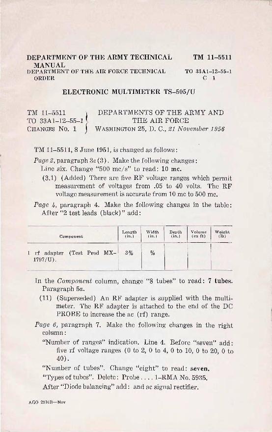
DEPARTMENT OF THE ARMY TECHNICAL MANUAL
TM 11-5511
DEPARTMENT OF THE AIR FORCE TECHNICAL ORDER
TO 33Al-12-55-1 C 1
ELECTRONIC MULTIMETER TS-505/U
TM 11-5511 } DEPARTMENTS OF THE ARMY AND TO 33Al-12-55-1 THE AIR FORCE CHANGES No.1 WASHINGTON 25, D. C., 2 1 November 1956
1
TM 11-5511, 8 June 1951, is changed as follows :
Page 2, paragraph 3c (3). Make the fo llowing changes: Line six. Change "500 mc/ s" to read: 10 mc. (3.1) (Added) There are five RF voltage ranges which permit
measurement of voltages from .05 to 40 volts. The RF voltage measurement is accurate from 10 mc to 500 mc.
Page 4, paragraph 4. Make the following changes in the table: After "2 test leads (black)" add:
L en g th \ Width
I Depth I Vo lu m e I W e ig ht
Componen t (in. ) ( in. ) (in . ) ( cu ftl (Ib)
rf adapter (Test Prod MX- 3% % 1797 / U) .
In the Component column, change ·"8 tubes" to read: 7 tubes. Paragraph 5a.
(11) (Superseded) An RF adapter is supplied with the multimeter . The RF adapter is attached to the end of the DC PROBE to increase the ac (rf) range.
Page 6, paragraph 7. Make the following changes in the right column: "Number of ranges" indication. Line 4. Before "seven" add:
five rf voltage ranges (0 to 2, 0 to 4, 0 to 10, 0 to 20, 0 to 40) .
"Number of tubes". Change "eight" to read: seven. "Types of tubes". Delete: Probe .... 1-RMA No. 5935. After "Diode balancing" add: and ac signal rectifier.
AGO 2n10ll- Nov

DC PROBE AND RF PROBE COMPARTMENT
DC PROBE C'LIPS
DC PROBE CABLE ' ,
Bi>.TTERY COVER
[IDj ADJ, CONTROL
([UNCTION] SWITCH
PI LOT LIGHT INDICATOR ~1ti'J~L JEWEL ~
GASKET METER
" -IZERoj '~.-:"II""."RF~'ADAPTER,--, • _ -~ , ADJ. CONTROL ~Jru
ro:c:Fblrr] SW I T C H
AC PROBE AND AC LI NE CORD CO MPARTM ENT
TM5511-CI_1
Figu1"e 3. (Superseded) Elect1"onic Multimetm" TS-505/ U, j?'ont panel.
11. Re packing (Superseded)
a. Before repacking the multimeter for storage or shipment, re
move it from service. (1) Remove the battery cover (fig. 3) from the front panel of
the multimeter. (2) Remove the batteries from the battery compartment. (3) Clean the battery compartment (par. 30c (3.1» if neces
sary and replace the battery cover.
b. Repack the multimeter in. the same manner as it was originally packed by reversing the unpackmg procedure (par. 9).
2
Page 11, paragraph 12b. Add the following after the last sentence: Place two batteries (BA-30) in the battery compartment (par.
19c) . Page 12, paragraph 15b. Make the following changes:
Line 3. Change ".5 mc/ s" to read: 10 me. Delete the last sentence. (1.1) (Added) To measure RF voltages, connect the tip jacket of
a test lead to the COMMON binding post (fig. 3). Connect the RF adapter to the end of the DC PROBE. Connect the other end of the RF adapter and the COMMON test lead
AGO 2910B
probe across the unknown voltage. Connect the alligator clip lead of the RF adapter to the low potential point on the equipment under test.
Page 15, paragraph 18a. (2) (Superseded) For RF voltage measurements (above 10
mc) refer to paragraph 18.1.
18.1 Reading and Measuring RF Voltages (Added)
Note. The procedures specified in this paragraph apply to measurement of RF voltages from 10 mc to 500 mc.
a. Reading RF Voltages. Read the RF voltages on the dc voltage scale of the meter (fig. 3). The most accurate readings are obtained when the meter pointer is within the upper one-third portion of the dc voltage scale.
b. Zeroing Meter for RF Measu1"ements. (1) Perform the starting operations outlined in paragraph 16. (2) Turn the FUNCTION switch to the +DC position. (After
the multimeter has warmed up, the meter pointer will probably be near, but not at, zero scale reading.)
(3) Turn the RANGE switch to the 2V-RX1 position. (4) Hold the DC PROBE and the COMMON probe tips to
gether, and turn the ZERO ADJ. control until the meter pointer indicates exactly 0 volt.
c. Measuring RF Voltages. (1) Turn the RANGE switch to a higher voltage scale than the
voltage to be measured. If the magnitude of the voltage to be measured is unknown, turn the RANGE switch to the 40V -RX10K position. If necessary, the RANGE switch can be rotated to a lower scale. This procedure will protect the multimeter from a severe overload which might damage the meter movement when measuring RF voltages.
Caution: Do not attempt to measure RF voltages greater than 40 volts rms. The RF adapter will be damaged if greater voltages are applied.
(2) Connect the DC PROBE tip to the end of the RF adapter. (3) Connect the alligator clip lead of the RF adapter to the
low potential point of the voltage to be measured. (Do not add extra length to the alligator clip lead; extra length will cause RF loop effects.)
(4) Connect the RF adapter tip to the high potential side of the RF voltage to be measured.
AGO 2910B 3
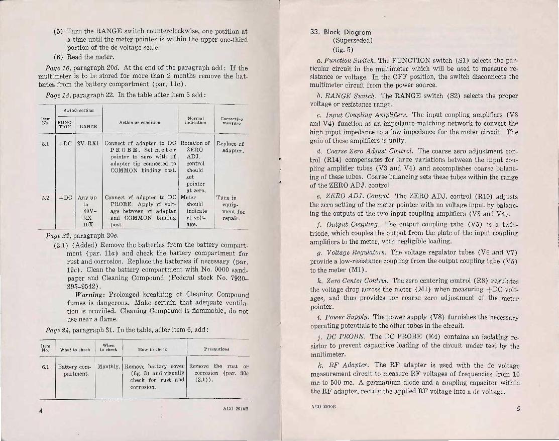
(5) Turn the RANGE switch counterclockwise, one position at a time until the meter pointer is within the upper one-third portion of the dc voltage scale.
(6) Read the meter.
Page 16, paragraph 20d. At the end of the paragraph add : If the multimeter is to be stored for more than 2 months remove the batteries from the battery compartment (par. lla).
Page 18, paragraph 22. In the table after item 5 add : _.
Switch setting
Item Normn) COl'rective No. FUNC- Action Or condition indication measlIre
TION RANGE
5.1 +DC 2V-RX1 Connect rf adapter to DC Rotation of Replace rf PROBE. Set met e I' ZERO adapter. pointer to zero with rf ADJ. adapter tip connected to control COMMON binding post. should
set pointer at zero.
5.2 +DC Any up Connect rf adapter to DC Meter Turn in to PROBE. Apply rf volt- should equip-40V- age between rf adapter indicate ment for RX and COMMON binding rf volt- repair. lOX post. age.
Page 22, paragraph 30c.
(3.1) (Added) Remove the batteries from the battery compartment (par. lla) and check the battery compartment for rust and corrosion. Replace the batteries if necessary (par. 19c). Clean the battery compartment with No. 0000 sandpaper and Cleaning Compound (Federal stock No. 7930-395-9542) .
Warning: Prolonged breathing of Cleaning Compound fumes is dangerous. Make certain that adequate ventilation is provided. Cleaning Compound is flammable; do not use near a flame.
Page 24, paragraph 31. In the table, after item 6, add:
Item When No. Wha t to check to check How to check P recautions
6.1 Battery com- Monthly. Remove battery covel' Remove the rust 01'
partment. (fig. 3) and visually corrosion (par. 30c check for rust and (3.1)) . corrosion.
4 AGO 2910B
33. Block Diagram (Superseded) (fig. 5)
a. Function Switch. The FUNCTION switch (Sl) selects the particular circuit in the multimeter which will be used to measure resistance or voltage. In the OFF position, the switch disconnects the multimeter circuit from the power source.
b. RANGE Switch. The RANGE switch (S2) selects the proper voltage or resistance range.
c. Input Coupling Amplifiers. The input coupling amplifiers (V3 and V 4) function as an impedance-matching network to convert the high input impedance to a low impedance for the meter circuit. The gain of these amplifiers is unity.
d. Coarse Z e1"O Adjust Cont1"ol. The coarse zero adjustment control (R14) compensates for large variations between the input coupling amplifier tubes (V3 and V4) and accomplishes coarse balancing of these tubes. Coarse balancing sets these tubes within the range of the ZERO ADJ. control.
e. ZERO ADJ. Control. The ZERO ADJ. control (RIO) adjusts the zero setting of the meter pointer with no voltage input by balancing the outputs of the two input coupling amplifiers (V3 and V 4) .
f. Output Coupling. The output coupling tube (V5) is a twintriode, which couples the output from the plate of the input coupling amplifiers to the meter, with negligible loading.
g. Voltage Regulators. The voltage regulator tubes (V6 and V7) provide a low-resistance coupling from the output coupling tube (V5) to the meter (M1).
h. Zero Center Control. The zero centering control (R8) regUlates the voltage drop across the meter (M1) when measuring +DC voltages, and thus provides for coarse zero adjustment of the meter pointer.
i. Powe'r Supply. The power supply (V8) furnishes the necessary operating potentials to the other tubes in the circuit.
j. DC PROBE. The DC PROBE (E4) contains an isolating resistor to prevent capacitive loading of the circuit under test by the multimeter.
k. RF Adapte?". The RF adapter is used with the dc voltage measurement circuit to measure RF voltages of frequencies from 10 me to 500 me. A germanium diode and a coupling capacitor within the RF adapter, rectify the applied RF voltage into a de voltage.
AGO 2910B 5
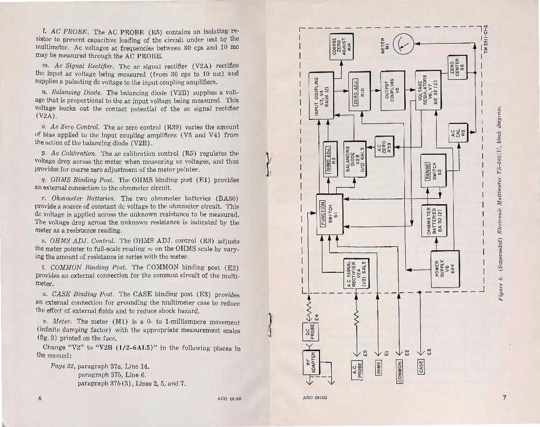
l. AC PROBE. The AC PROBE (E5) contains an isolating resistor to prevent capacitive loading of the circuit under test by the multimeter. Ac voltages at frequencies between 30 cps and 10 mc may be measured through the AC PROBE.
m. Ac Signal R ectifie?". The ac signal rectifier (V2A) rectifies the input ac voltage being measured (from 30 cps to 10 mc) and supplies a pulsating dc voltage to the input coupling amplifiers.
n. Balancing Diode. The balancing diode (V2B) supplies a voltage that is proportional to the ac input voltage being measured. This voltage bucks out the contact potential of the ac signal rectifier (V2A).
o. Ac ZeTO Control. The ac zero control (R39) varies the amount of bias applied to the input coupling amplifiers (V3 and V 4) from the action of the balancing diode (V2B).
p. Ac Calibration. The ac calibration control (R5) regulates the voltage drop across the meter when measuring ac voltages, and thus provides for coarse zero adjustment of the meter pointer.
q. OHMS Binding Post. The OHMS binding post (El) provides an external connection to the ohmmeter circuit.
r. Ohmmeter Batteries. The two ohmmeter batteries (BA30) provide a source of constant dc voltage to the ohmmeter circuit. This dc voltage is applied across the unknown resistance to be measured. The voltage drop across the unknown resistance is indicated by the meter as a resistance reading.
s. OHMS ADJ. Control. The OHMS ADJ. control (R3) adjusts the meter pointer to full-scale reading 00 on the OHMS scale by varying the amount of resistance in series with the meter.
t. COMMON Binding Post. The COMMON binding post (E2) provides an external connection for the common circuit of the multimeter.
u. CASE Binding Post. The CASE binding post (E3) provides an external connection for grounding the multimeter case to reduce the effect of external fields and to reduce shock hazard.
v. Mete?". The meter (Ml) is a 0- to I-milliampere movement (infinite damping factor) with the appropriate measurement scales (fig. 3) printed on the face.
Change "V2" to "V2B (1/2-6AL5)" in the following places in the manual:
6
Page 32, paragraph 37a, Line 14. paragraph 37b, Line 6. paragraph 37b (3), Lines 2,5, and 7.
AGO 2910n
r----1 Lr./ l-
(J')O(J')
I n:n:::>v C5~3cr
I u <t
I J I (!) z :J 0.. @ ~ ::>v-
O>CD U 00::> I-><t :::> CD 0.. ~
.. ~§~-I z ~(J')
~ (J')
I I I I I I L ___ _
>
V Lr./
'm [ill ~o on:
0..
0:: Lr./
11.1-o::~
° «
AGO 2910B
~2 ~ 0:: Lr./ N
t
-- -- -
n:
~ Lr./ .... -Lr./::E ::E
I-(!) ::>~
f-+ 0.....J1t) r--. 1-0..> ::>:::> 00
u r-
- _. -----i N , • I
U
~ -
-(J') n: Lr./O ~
(!)I-r-- N <t<t>-
~3ti~ ~~>Lr./
0:: Z
•
0:: 0Lr./ n:1-<Xl Lr./zn: NLr./
u
j
...........
1= It)
I~ ( I I I I I I
I I I
f-----~ -------1
7

Page 34, Figure 10. Change "a-c probe" to "ac signal rectifier" in the following places
in the manual.
Page 32, paragraph 37a, Line 9 and 12. paragraph 37b, Line 7.
Page 42, paragraph 47c. Line 5, after "nonfunctioning".
Page 32, paragraph 37b (3). In lines 2 and 9 change "VI" to read: V2A (1/2-6AL5).
Page 35, paragraph 39.
a. (Superseded) The AC PROBE (fig. 22) contains a resistor (Rl) mounted in the holder. The resistor prevents capacitive loading of the circuit under test by the multimeter. The ac circuit, consisting of a diode (V2B, 1/ 2-6AL5) connected in the circuit as a half-wave rectifier and input coupling capacitor (C2), and an input resistor (R45), permits accurate measurements up to 10 mc. Because of the high value of the input resistor (15 megohms) and the input capacitor (10,000 /J:jJ-f), the diode is essentially a peak rectifier. Diode V2A (1/ 2-6AL5) acts as a balancing diode and is used to oppose the contact potential of diode V2B with no input signal applied to the AC PROBE. This balancing is accomplished by rotating resistor R39 until zero deflection on the meter is attained, with the AC PROBE tip connected to the COMMON binding post.
39.1 RF Voltage Measurement Circuit (Added)
a. Except for the addition of the RF adapter (fig. 11), the RF voltage measurement circuit is the same as the dc measurement circuit described in paragraph 37.
b. When in use, the RF adapter is connected to the DC PROBE. The RF adapter functions as a half-wave rectifier to convert the RF voltage being measured to a pulsating dc voltage.
CI .0001 R46 TO
< ,', I ~ , , PROBE B.2MEG
E4
GERMANIUM DIODE
CRI IN70
TM5511-CI-3
Figtt1'e 11. (Superseded) RF acla1Jte1', schematic diag1·am.
8 AGO 2910B
;.
Page 37, paragraph 42a. At the end of the second sentence delete "(fig. 12)".
Page 38, figure 12. Rescinded.
Page 61, figure 20. Rescinded.
Page 62, figure 21. Rescinded.
Page 39, figure 13. Add the following Note: NOTE: SP ARE DIODE ASSEMBLIES ARE NOT SUPPLIED WITH
THE TS- 505/U.
Page 44, paragraph 50b. Make the following changes in the table: After item 15 add:
Switch position Probable Remedial
Abnormal indication fa ult action 81 I 82
15.1 Any up to No deflection of meter pointer a. Capacitor a. Replace
+ DC. 40V- (with rf adapter connected Clopen rf adapt-
RXI0K. to DC PROBE, and rf volt- or short- er. age up to 40 volts, 10 mc to ed. 500 mc applied). b. German- b. Replace
ium diode rf adapt-CRlopen er. or short-ed.
c. Resistor c. Replace R46 open. rf adapt-
er.
Item 31. Delete. Make the following changes in the Probable fault column: Item 23a. Change "Rl" to read: Resistor R45. Items 24a and 25. Change "Cl" to read: Capacitor C2. Items 24b and 28a. Change "VI" to read: Tube V2. Make the following changes in the Remedial action column: Item 23a. Change "with spare diode assembly" to read:
resistor R45. Items 24a and 25. Change "a-c probe assembly" to read:
capacitor C2. Items 24b and 28a. Change "with spare diode assembly" to
read: tube V2. Item 28b. Delete. Item 28c. Change "with spare diode assembly" to read:
resistor Rl.
AGO 2910B 9

DC PROBE CABLE
METER --.._;=
4J2
AC li NE CORD
TM 6511-CI-4
Figure 15. (Superseded) Elect?·onic Multimeter TS-505 / U, unde?· side of te?·minal board.
Page 54, figure 16. On tube socket V2 6AL5 make the following changes:
Pin 1. Change "1,450" to read: O. Pin 7. Change "3 MEG" to read: INFINITY.
Page 55, figure 17. On tube socket V2 6AL5 make the following changes :
Pin 1. Change "0" to read: -.2V. Pin 2. Change "-.5V" to read: -.25V.
Page 59, paragraph 53. Rescinded.
Page 63, paragraph 56a.
a.1. (Added) Remove the batteries from the compartment (par. lla).
Page 67. Appendix II. Rescinded.
10 AGO 2910B

0
ci. Q) ()
os rot
~ '" '" -.j'
'" c5 p.; 0
'" 0
'" '" -.j' 0 N
'"
---- -------"/1--- - - - -----:;;r / I r-----------------~~----------------------------~~------~----------------,
I .- -y I 1.--21----/ 1
- -- - - -- -- 71
.-- __ 2' ____ / I
.,,,, ,X" .AA
R9RI0 'RII r -1
~ PROBE
~ PROBE
~ ,- __ ....J
E5 RI 220
R2
,-, I 5 MEG -,
~ ir 1 ___ ...J
E4
CI R46 TO .0001 8.2MEG ~ lo.c , PROBE]
?~~I:l'A'-:~f,~--~r-" E4
.. 1~~6 /'
RF ADAPTER
I .L-:-: _9_"~':/ 1 I : ~~tJ,[Y: i I ""V 3 I I : .A® 3 : I
I ~-~ f I ~ f ~---.--'-f-, II 2 ') I 2 I )
I SEf;~~~ I II II SECTION 2 II
FRONT
L-~--~~--I-t Y I y/
, ~ / I
1 J 5 I
I I 9" I
i-}~}-3 1 I I I II f 2 I
~ I SECTION 3 I 1,.-: I FRONT
I / I I ,
c' ® I R45 . I:: (Ef::: : I fr)i("-:- I
R3 2,500
10HMS] ADJ. ~
R4 1,450 1 t / I I ~ I '
I ~~~_\ t{ 4 I g~ I 8 \ J,,/ I I 8~Js.,< :
10 ~[ : 15 ~~G I : C 0 ... I II FUN~~'ON I 12 'j1--+-7,-+---..JVv\'-~ : ~ f I : I 10 ~2f I II R5
00 (SEE NOTES SE~~'2~ I I I SECTION 2 : 1 ' 1 2~
I 3,4,6 ) L ______ J L __ ~~R __ _.J I I -~C
~~~EG I SECT ION 3 I CAL R7 lOOK
R8 SOK
ZERO .~NTER
150K 25K 150K INPUT IZERO ADJ.I INPUT
COUPLING COUPLING
V3 R 12 6~~6
~ ______ 6+A_U_61J Fri21-":: -_,~ "~ I '~ • ~..J ~ -- I 7r-- 7
C6 ,01
L--
I 1
C7 .02
RI3 82K
EE~I ______________ -!r-~~~j~----~--------r~~ ______ -r ____________ -t===3==E===E====I=L==-==-===~iEA=~==-==-]:J======~---J [OHMS] ~ /
(COMMO~ ~~ ______ ------------------/~~--------1rll----------l-------------~---r----~~-----------t-t--i---~------+-~-J~---1~::::==============+=~--r_------_tt_t_1 E2
OUTPUT
COUPLING vs
12AT7
/ /
/
/ /
/ / C4
~ _______ -..--+_~.O~I~ i' .--- __ 2L_ - -- 1 ~
CS .01
S2
[@ill (SEE NOTE S
3,5,6)
I RI8 @ I " R~ I I S R 16 R 15 ,,5 OK R30
I MEG 4.SMEG JE~ I "-. 5~K
:~~gK 7 54 3 ~l: I ; "~-2~5 --32~ I \ I ~.\, , 1
I R20 < .... © I I 9 .... ",,'" I I I 450K :. 9 .... " +- I ~.
R29 150K
R28 2S0K
R39 S MEG
L-__ -l--+< AC ZERO
BALANCING
DJ~~EF ,t"'" ~ I
I
6~7 --
I
NOTES :
AC SIGNAL RECTIFIER
V2A (t)6AL5
• . ..,.. VOLTAGE
'----1 REGULATORS ~ R40 R41 22K<" V6 V7 .... 22K
r NE-32 NE-32 r
J
I SI / TI 3 1
SECTION 4 / F I iW~-+-------'
~ I~ 155".o~VDC ~8;:;9
~ !f:6.3V _'+1_ .......... 6 ....
I ~ t~~ 17 I II .... , , ..... 17 I L-----_~-__+-J '- I I R25 ,t I
I 12 " R23 I 13 15 ', 30MEG I ~E~ I~ 15
II " -"v- I R21 R22 ' ~ R26 R27
I. UNLESS OTHERWISE INDICATED, RESISTANCES ARE IN OHMS, CAPACITANCES ARE IN UFo
2. c==J INDICATES EOUIPMENT MARKING. 3, IFUNCTIONI SWITCH SI AND IRANGEI SWITCH S2 ARE VIEWED FROM REAR. SECTIONS DESIGNATED I ARE CLOSEST TO KN08.
4 , IFUNCTIONI SWITCH SI IS SHOWN IN IQIT] POSITION.
5. IRANGI] SWITCH S2 IS SHOWN IN 12V-RX] POSITION.
;;MP i~5AMP (-:L -=--) "*' /7
R42 3,300 A' '"
150K 75K I I 1.5MEG 500K
I SECTION 2 I ~ A
I ' I StCTl ON I
I REAR I ~ '"", I , FRONTA
6. SWITCH POSITIONS AND CONTACTS MADE:
[fUNCTIONI I RANGE I SI S2
CONTACTS MADE SWITCH
CONTACTS MADE RECTIFIER V8 I ~ :1 I i !iR
?; .;:~ib ~~2 SWITCH SECTION I SECTION I SECTION 2 SECTION 2 SECTION 3 SECTION 3 POSITION SECTION I SECTION I SECTION 2 5 ECTION 2
PI 115V
50-1600 CP S
6X4 RI4 6
COARSE ZERO
ADJUST
2 P ? 9 If :~...-----J\/V\,-,t : V8 EI3 V2 VS V3 V4
I I R35"-. E 4 I ~ I I 30K 8 " ~
I 0~ II I I ~,/ 2 -~ I ~ ~~r.-~~1~8~ ____ ~
I 16 '- I I R';~ 10 .... , " '- I 300 K 't \ I IS , I I .A 12
I SECTION 2 I' I I 'VR~7 >'4
L ___ ~ONT ___ J ~ I 3 MEG ~ 3~ t~G
~ I SECTION I L ___ ~~ __ J
POSITION FRONT REAR FRONT REAR
[Q0 10HMSI 2, 3
2, 3
I +D.C· I 2, 5 4,6 2, 5 - 2 , 7 I, 8
::l I sD.C·1 2, 7 4, 8
I - D. C. I 2,9 4,10 2,9
[g] 2, II 4,12, I
Figure 22. (Superseded) Electronic Multimeter TS-505/U, schematic diagram.
FRONT REAR FRONT REAR FRONT REAR
12V-RXI I 9, II 18,2 15, 16 I 2, I
2, 3 1,4 14V- RX101 9, 13 18,4 IS, 16 I 2, 3,4
2, 5 1,6 I,OV-R X 1001 9, 15 18, 6 15, 16 12 ,5
2, 7 1,8 120V-RX 10001 9, 17 18, 8 15, 16 12,7
2,9 1,10 140V-RXIOKI 9, I 18, 10 15, 16 12,9
2, II I, 12 IIOOV-RX IOOKI 9, 3 18, 12 IS, 16 12, II
1200V-R X I MEG I 9, 5 18,14 15, 16 12,13
1400V- D.C.ONLY I I S, 16 12, IS
11000V-D.C.ONLy l 12, 17
TM 5511 -CI- 5

[AG 413.6 (8 Nov 56) J
By ORDER OF THE SECRETARIES OF THE ARMY AND THE AIR FORCE:
MAXWELL D. TAYLOR, Geneml, United States A1'1ny,
OFFICIAL: Chief of Staff. JOHN A. KLEIN,
Mafor Gene1"al, United States Army, The Adfutant General.
N. F . TWINING, OFFICIAL: Chief of Staff, United States Air Force.
E. E . TORO, Colonel, United States Ai1' Force,
Air Adfutant Gen81"al.
AGO 2910B 11

=.
Distribution:
12
Active A?"'Iny:
CNGB (1) ASA (3) Tec Svc, DA (1) except
CISGO (30) Tec Svc Bd (1) Hq CONARC (5) CON ARC Bd (Incl ea test
sec) (1) Army AA Cornd (2) OS Maj Cornel (5) OS Base Comd (5) Log Comd (5) MDW (1) Armies (5) Corps (2) Inf Div (2) Armd Div (2) Ft & Cp (2) Sp Wpn Comd (2) Army Cml Cen (9) USMA (5) Gen & Br Svc Sch (5) ex
cept Sig Sch (25) Gen Depot (2) except
Atlanta Gen Depot (none)
Sig Sec, Gen Depot (10) SigDepot (17) US Army Tng Cen (2) PSYWAR Cen (5) POE (OS) (2) Trans Terminal Comd (2) Army Terminal (2)
OS Sup Agencies (2) WRAMC (5) Army Elct PG (1) Aberdeen PG (5) Jefferson PG (5) Redstone Arsenal (5) Sig Fld Maint Shops (3) Sig Lab (5) ACS (3) Mil Dist (1) Units org under fol TOE:
5-278R (2) 5-500R (AA- AD) (2) 9- 510R (2) 11-7C (2) 11-15C (2) 11-16C (2) 11-18C (2) 11-57C (2) 11-127R. (2) 11-128C (2) 11- 500R (2) 11-557C (2) 11- 587R (2) 11- 592R (2) 11-597R (2) 32- 51R (2) 32-55R (2) 32-56R (2) 32-57R (2) 32- 500R (2) 33-67R (2)
NG: State AG (6); units-same as Active Army except allowance is one copy per unit.
USAR: None. For explanation of abbreviations used, see SR 320-50- 1.
U. S, GOVERNMENT PRINTING OFFICE: 1956-400517
AGO 2910B

TM 11-5511 TO 33Al-12-55-1
·C 3
DEPARTMENT OF THE ARMY TECHNICAL MANUAL
DEPARTMENT OF THE AIR FORCE TECHNICAL ORDER
ELECTRONIC MULTIMETER TS-505/U
TM 11-5511 ) TO 33A1-12-55-1 CHANGES No. 3
DEPARTMENTS OF THE AL~Y AND THE AIR FORCE
WASHINGTON 25, D.C., ~8 July 1960
TM 11-5511/TO 33A1-12-55-1, 8 June 1951, is changed as follows:
Note. The parenthetical reference to previous changes (example: ("page 10 of C 1"» indicates that pertinent material was published in the changes.
Page 15, paragraph 18a. Make the following changes: Heading. Add the following warning notice below the heading:
Warning: If line voltage measurements are to be made, a potential hazard will exist unless the multimeter case is grounded to an external ground.
Subparagraph a(1). Add the following note after the subparagraph:
Note. Erratic meter indications may occur when the multimeter is set to the low ac voltage range. Ground the case of the multimeter to an external ground to eliminate this problem.
Page 16, paragraph 19. Add subparagraph d after - subparagraph 0:
d. Limitations and Qualifioation of Resistanoe Readings. (1) Misinterpretation of resistance readings obtained with
Electronic Multimeter TS-505/U can result in unnecessary repairs to equipment, because resistors are mistakenly reported faulty.
(2) The tolerance prescribed for the TS-505/U is ±4 percent of arc length. The ±4 percent of arc length does not result in a +4 percent resistance value reading. The possibh indicated resistance of any resistor can be determined by using a computing device similar to that shown in figure 4.1. Figure 4.1 shows that a resistor rated at exactly 30 ohms could produce a reading on t11e TS-505/U between 25.5 and 35.5 ohms, with only 4 percent meter tolerance. If the resistor has a tolerance of +10 percent, the meter reading obtained will be between 22.7 and 38.1 ohms as shown in figure 4.2.
-These changes supersede C 2, 27 October 1958.
TAGO 71lB-Aug. 570478'-60 1

2
OH MS SCALE
RESISTOR WITH 0 TOLERANCE
SHADED AREA INDICATES POSSIBLE READINGS DUE TO METER TOLERANCE ,±4% OF ARC LENGTH
TM5511-C3-1
Figtlre 4.1. (Added) Oomptttinu device, indicating mete1' toZe1·ance.
(3) A computing device similar to the one illustrated in figure 4.3 and calibrated as shown can be constructed of cardboard.
" '1'he center scale can then be made to rotate and the device used as an aid for determining the limits between which a resistor tested with Electronic Multimeter TS- 505/U is acceptable. The following examples show the step-by-step procedure for using the computing device.
Examples: 1. Calculation for ± O-percent resistor. a. Place ± 0 line at 30 on the ohms scale. b. Read the ohms value, two divisions above and below ±o. c. These readings are 25.5 ohms and 35.5 ohms (fig. 4.1).
TAGO 7UB

LOWER LIMIT READING DUE TO RESISTOR VALUE RESISTOR TOLERANCE t 10% IjUPPER LIMIT READING DUE TO
RESISTOR TOLERANCE ~ 10% LOWER LIMIT READING DUE \ UPPER LIMIT READING DUE TO RESISTOR PLUS METER TO RESISTOR PLUS METER rOLERANCE TOLERANCE
\, ~\ -,;f.<-...J... j
TM5511·C3·2
FiUlt1"e 1.:13 .• (A.clclecl) Oomputing clevice, inclicatinu metel· and resistance tolemnce.
2. Calculation for ± 10-percent resistor. H.. Compute resistor extremes. b. These extremes are 27.0 ohms and 33.0 ohms. c. Set ±O line to 27.0 ohms on the ohms scale and read the
ohms value, two divisions to left of ± O. d. This reading is 22.7 ohms (fig. 4.2). e. Set ± 0 line to 33.0 ohms on the ohms scale and read
ohms value two divisions to right of ±O. f. This reading is 38.1 ohms (fig.4.2).
Page 133, pa.ra.graph 300. Add the following caution after subparagraph (4).
Caution: Damage to switch contacts and wiring can result from Iealdng batteries. Inspect the batteries at least once each month or oftener during hot weather.
Page 136, paragraph 31, item No. 15, "Precautions" column. (As changed by C 2, 27 Oct 58) Add the following: For proper operation of Multimeter TS-505/U, the two glow tubes (voltage regulator tubes TAGO 711B 3

TM55fl-C3-3
F'ig!t1'O 4,3, (Aclcled.) Oomputing d.evice fOl' d.etermining limits of acceptabiUtv for ,'es'isto1'8 tested. with Electl'ol1ic MulUmetel' 7'S-505/U.
V6 and V7) must be installed so that the outer spiral electrode glows during operation. To accomplish this, plug the power cord into an appropriate ac power source and operate the FUNCTION switch to OHMS. 'Wait the required warmup time, and then check to see that the oute1' spiral electrodes of both tubes are glowing. If the inne1' electrode of either tube is glowing, remove that tube, rotate it 1800
, and replace it in the socket. Page 44, paragraph 50. (As changed by C 2, 27 Oct 58) After
su bpara,graph a, add: Note, Before making resistance measurements in a defective TS- 505/U, dIs
connect the ac power source aud remove the two BA- 30 batteries from the battery compartment,
Page 55, figure 17 (page 10 of C 1). (As changed by C 2,27 Oct 58) At pin 1 of tube socket V2 6AL5, change "-.2V" to read: O.
Page 6"/. Appendix II was deleted by C 2, 27 Oct 58.
" TAGO 711B

By ORDER OF THE SECRETARmS OF 'l'HE AnllIY AND THE Am FORCE:
OFFICIAL:
R. V. LEE, Major Geneml, United States A1'my,
The Adjutant Gene1'al.
L. L. LEMNITZER, Gene1'al, United States A 1'1nY,
Ohief of Staff·
THOMAS D. WHITE, OFFICIAL: Ohief of Staff, United States Ai?' Force.
J. L. TARR, Oolonel, United States Ai?, F01'ce,
D,t?'ector O'f Administrative Se?'Vices.
TAGO 711B

DISTRIBUTION: Active Army:
To be distributed in accordance with DA Form 12-7 requirements for TM 11 Series (UNCL) plus the fOllowing additional formula:
USASA (2) 11-07 CNGB (1) 11-98 Def Atomic Spt Agcy (5) 11- 117 ~'ech St!, DA. (1) except OSigO 11-155
(18) 11-157 USA Abn & Elct Bd (1) 11-158 USA ATB (1) 11-500 (Tms AA-AE) US ARA.DOOM (2) 11-555 US ARADCOM Rgn (2) 11-557 MDW (1) 11-558 Seventh US ArlUY (5) 11-587 EUSA. (5) 11-592 Corps (2) 11-597 JBUSMO (2) 11-608 Units organized under following
TOE's: (2 copies each) 1-7 1-17 1-37 1-67 1-107 5- 8 5-278 5-500 (Tms AA-AD) 5-600 5-605 6-100 6-101 6-300 6-301 6-315 6- 316 6- 630 7 7-52 9- 217 9-510 11-5 11-6 11-7 11-8 11-15 11- 16 11-38
17 17-51 20-51 29-55 29-56 29-57 32-51 32-55 32-56 32-57 32-500 33-56 33- 57 (Tms AA-AO) 39- 51 39- 52 39-61 44- 12 44-101 44--435 44--437 44-445 44-446 44-447 44---"148 44-535 44-537 44-544 44-545 44-546 44-547
11-55 44-548 11-56 44-549 11-57 55-157 11-58
NO: State AG (3); UnIts-Same as Active ~rmy except all copy to each unit. owance is one
USAR: None. For explanation of abbeviatlons used, see AR 320- 50.
TAGO TUB u.s. GOVERNMENT PRtNTlHC; OFFICE: 1110