electronic shear pin model esp 1 & 2 - zener · esp product warranty zener electric warrant the...
TRANSCRIPT

ELECTRONIC SHEAR PIN MODEL ESP 1 & 2
INSTRUCTION MANUAL
ESP Product Warranty
Zener Electric warrant the Electronic Shear Pin against defective workmanship and materials for a period of 24 months from the date of despatch. Such defects will be rectified free of charge for both labour and material, at Zener Electric premises subject to: 1. Zener Electric customer raising an order upon Zener for service and/or repairs, subject to a warranty claim. The order is to state particulars of the model and serial number, the date of original purchase and invoice/delivery docket number. 2. All damage resulting from incorrect installation or use other than in accordance with the instruction manuals issued by Zener Electric is excluded from this warranty. 3. The warranty being rendered invalid if the product is misused or if any unauthorised alteration, modification or substitution of any part of the product be made or the serial number of the product is defaced or altered. 4. The cost of transportation (both ways) is to be met by the owner if it is necessary to return the product, or any part of it, to Zener Electric’s premises. 5. A charge being accepted by the owner for travelling time and expenses incurred in connection with warranty service at the user's site as requested by the owner. 6. If the product was not purchased from Zener Electric directly, then a warranty claim must be lodged with the original supplier in the first instance. Repairs will not be effected by Zener Electric unless approved by the original supplier. Goods not of our own manufacture incorporated in our supply or sold by us, carry their makers warranty. 7. Goods returned for claim under warranty will be accepted on the condition that should the claim be rejected than all costs, including inspection, will be charged to the customer's account. 8. Zener Electric is not liable for any consequential loss

Scope This document is a guide for the installation and operation of the Electronic Shear Pin 1 and 2. The ESP 2 has the same functionality as the ESP 1, but provides additional features which are identified throughout the manual. All warnings and recommendations should be followed and in case of uncertainty, please contact Zener Electric.
Receiving Inspect the ESP for shipping damage. If any damage is found report it to the carrier immediately. Do not attempt to operate the ESP if any obvious damage exists.
Caution
Read this manual completely before connecting and operating this equipment.
Warning This equipment must always be applied, installed and used in a safe manner, in accordance with the various regulations and accepted good practices covering industrial safety. It should not be used as "stand alone" protection in applications where there exists the possibility of personal injury or property damage in the event of a mechanical or electrical malfunction of any part of the machine or system.

Zener Electric Pty Ltd ELECTRONIC SHEAR PIN MODEL ESP1 & 2
INSTRUCTION MANUAL IM00064B Page 1
TABLE OF CONTENTS
Section Page
1. General .....................................................................................2
1.1 Features - ESP1 & 2 .........................................................2 1.2 Additional Features - ESP 2 ..............................................2 1.3 Terminal Functions............................................................2
2. Specifications............................................................................3
3. Matching to different motor sizes ..............................................4
3.1 Non-standard Motor Matching...........................................4
4. Installation.................................................................................9
4.1 Mechanical Installation ......................................................9 4.2 Electrical Installation .........................................................9
Figure 1. 3Phase connection diagram ..........................10 Figure 2. 1Phase connection diagram ..........................11 Figure 3. CT Model 701 connection diagram................12
5. Commissioning .......................................................................13
5.1 Setting up........................................................................13 5.2 Functional Test................................................................14
6. Operation ................................................................................15
7. Maintenance ...........................................................................15
7.1 Load Measurement Calibration .......................................15 7.2 Phase Loss/under voltage Trip Calibration......................15

Zener Electric Pty Ltd ELECTRONIC SHEAR PIN MODEL ESP1 & 2
INSTRUCTION MANUAL IM00064B Page 2
1.0 General Information
1.1 Features - ESP 1 & 2 The Electronic Shear Pin model ESP 1 & 2 monitors the current drawn by an A.C. induction motor in a manner that closely approximates the torque output of the motor. Should the output torque of the motor exceed a preset point for a preset length of time, the Electronic Shear Pin will trip, disconnecting the motor from its electrical supply. A starting time delay circuit is provided to prevent a trip condition arising while the motor is accelerating to normal running speed. Light emitting diodes are provided to indicate the status of all internal functions. An internal test signal has been provided for initial calibration of the trip point and for use as a convenient functional test of the entire trip system. 1.2 Additional Features - ESP 2 The Electronic Shear Pin model ESP 2 provides additional features as follows: • Motor Under Voltage - adjustable under voltage trip point which can be enabled or disabled during the start time. • Phase Loss Protection - can be enabled or disabled during the start time. 1.3 Terminal Functions L and N : Power to run the Electronic Shear Pin, 240 VAC +/-10%, 50/60 Hz. Interrupt this power supply to reset the unit remotely. RT1 and RT2 : Apply power (240 VAC) to these terminals to signal the Electronic Shear Pin that the motor has been started. The start time delay is started as power is applied to these terminals. SH1 and SH2 : Connections for the secondary of the current transformer monitoring motor current. It must be a 5 Amp secondary type, polarity is unimportant but the current transformer must be fitted to the motor lead connected to terminal L1. L1, L2 and L3 : These terminals connect to the motor voltage to give the Electronic Shear Pin a phase reference to use in assessing the motor load. In 3 phase applications, phase rotation doesn't matter, but the current transformer must be fitted to the motor lead connected to L1. In single phase applications use only terminals L1 and L2.

Zener Electric Pty Ltd ELECTRONIC SHEAR PIN MODEL ESP1 & 2
INSTRUCTION MANUAL IM00064B Page 3
Relay Contacts : These contacts provide the signal to stop the motor when a trip occurs. The relay is de-energised during normal running and energises when a trip occurs. Note that this relay also energises when the RESET switch on the Electronic Shear Pin is operated.
2.0 Specifications
Power Supply 240 VAC, +/- l0%, 50/60 Hz.
Motor Voltage 200 to 440VAC.
Motor Size Any
Motor Type Single or 3 phase induction
Current Transformer Type 5A secondary, 5VA
Current Transformer Secondary In phase component:
Motor Load Meter Scale 0 to 150%
Internal Test Signal 0 to 150%
Trip Point Range 0 to 150%
Trip Time Delay 0.15 to 20 seconds
Motor Start Time 0.15 to 20 seconds
Relay Contact Ratings 240 VAC, 2A (resistive load)
Ambient Temperature Range 0 to 50 degrees Celsius
Enclosure IP00
ESP 2 Only
Undervoltage Trip Selectable, -5% to 20%
Phase Loss Selectable, loss of phase protection

Zener Electric Pty Ltd ELECTRONIC SHEAR PIN MODEL ESP1 & 2
INSTRUCTION MANUAL IM00064B Page 4
3.0 Matching to Different Motor Sizes Adaptation of the Electronic Shear Pin to a specific motor rating is achieved by the selection of an appropriate current transformer and the adjustment of four range selection switches. The switches are provided to "fill in" the gaps between standard current transformer ratios. For motors of modern design, in standard metric frames, Table 1 page 5 permits current transformer selection and switch setting with sufficient accuracy for most purposes. Should it be desired to use the Electronic Shear Pin with a motor not listed in Table 1 then proceed to section 3.1. Note: The range selection switches are located at the front of the Electronic Shear Pin near the terminal strip. These switches are closed by pressing the button above the number and opened by pressing the button below the number. More information about the location and setting of the range selection switches (SWA1 to SWA4) can be found on Pages 10 or 11.
3.1 Non-standard Motor Matching Stage 1: To select a suitable current transformer, calculate the values of A as shown below with an initial value of C = 1. If a standard current transformer with a primary current rating between A and B is available, use it with a single wire through the hole in the centre of the transformer (1 primary turn). If no standard current transformer falls between A and B, increase the value of C (to 2, 3, 4 etc) until it does. This value of C is the number of primary turns to use in the current transformer. A current transformer of the toroidal type will have to be used if more than 1 primary turn is required. The current transformer used must have a 5 Amp secondary winding. Other types should not be used. A = 1.25 x MOTOR FULL LOAD AMPS x FULL LOAD POWER FACTOR x C B = 2 x MOTOR FULL LOAD AMPS x FULL LOAD POWER FACTOR x C Note: For motors having full load current ratings between about 0.5 and 3 Amps, the Z701 transformer is available. For the Z701 Current Transformer, the primary current ratings can be read from the table in Figure 3 on page 12.

Zener Electric Pty Ltd ELECTRONIC SHEAR PIN MODEL ESP1 & 2
INSTRUCTION MANUAL IM00064B Page 5
Table 1: Matching the ESP1 to motor size (Nominal full load ratings at 415V, 3 phase, 4 pole motors)
MOTOR RATINGS POWER CURRENT TRANSFORMER SWITCH SETTINGS
kW AMPS FACTOR TYPE PRIMARY TURNS 1 2 3 4
0.18 0.56 0.75 Z701 CONN.A O O O C 0.25 0.72 0.76 Z701 CONN.A C O O C 0.37 1.03 0.76 Z701 CONN.B C C O O 0.75 1.79 0.8 Z701 CONN.E O C O O 1.1 2.2 0.84 Z701 CONN.F O C O C 1.5 3.4 0.82 50/5 10 O O C C 2.2 4.78 0.83 50/5 7 O O C C 3 6.44 0.83 50/5 7 C C O O 4 8.1 0.83 50/5 4 O O C O 5.5 10.8 0.85 50/5 3 O O C C 7.5 14.4 0.85 50/5 3 C C O O 11 20.2 0.86 50/5 2 C O C O 15 26.7 0.88 75/5 2 O C C O 18.5 33.2 0.85 50/5 1 O C O O 22 40.5 0.83 50/5 1 C O O C 30 55.2 0.83 75/5 1 O C C O 37 67.2 0.84 75/5 1 C C O C 45 76.1 0.88 100/5 1 C O O O 55 95.7 0.86 150/5 1 O O C O 75 129 0.86 150/5 1 C C O O 90 155 0.86 200/5 1 C O O O 110 189 0.86 300/5 1 O O C O 132 225 0.87 300/5 1 C O O O O = switch open C = switch closed

Zener Electric Pty Ltd ELECTRONIC SHEAR PIN MODEL ESP1 & 2
INSTRUCTION MANUAL IM00064B Page 6
Stage 2: Having chosen a suitable current transformer evaluate the value of S. S = MOTOR FULL LOAD AMPS x FULL LOAD POWER FACTOR x 5 x PRIMARY TURNS CURRENT TRANSFORMER RATED PRIMARY AMPS Your answer should be a number between 2.5 and 4.0. If it is outside this range you have probably made an error in the current transformer selection calculations in stage 1. Example: We have a 15 kW motor with full load current of 27 Amps at 0.88 power factor. For C = 1 A = 1.25 x 27 x 0.88 x 1 = 29.7 B = 2 x 27 x 0.88 x 1 = 47.52 There is no current transformer available with a primary rating between A and B so we will try C = 2. For C = 2 A = 1.25 x 27 x 0.88 x 2 = 59.4 B = 2 x 27 x 0.88 x 2 = 95.4 A 75/5 toroidal current transformer is suitable with the motor lead passed through the transformer twice (C = 2). We now calculate a value for S to determine the range switch settings. S = 27 x 0.88 x 5 x 2 = 3.17 75 Use S = 3.2 in table 2 as this is the nearest value. Stage 3: Select the appropriate line in table 2 for the value of S that you have just calculated and set the switches of switch SWA (range selection switch) to the positions indicated.

Zener Electric Pty Ltd ELECTRONIC SHEAR PIN MODEL ESP1 & 2
INSTRUCTION MANUAL IM00064B Page 7
Table 2 : Range selection switch SWA
S SWA 1 2 3 4 2.5 O O O O 2.6 O O O C 2.7 O O C O 2.8 O O C C 2.9 O C O O 3.0 O C O C 3.1 O C C O 3.2 O C C C 3.3 C O O O 3.4 C O O C 3.5 C O C O 3.6 C O C C 3.7 C C O O 3.8 C C O C 3.9 C C C O 4.0 C C C C
O = Switch Open C = Switch Closed Note: The range selection switches are located at the front of the Electronic Shear Pin near the terminal strip. These switches are closed by pressing the button above the number and opened by pressing the button below the number. More information about the location and setting of the range selection switches (SWA1 to SWA4) can be found on Page 10 or 11.

Zener Electric Pty Ltd ELECTRONIC SHEAR PIN MODEL ESP1 & 2
INSTRUCTION MANUAL IM00064B Page 8
Stage 4: ESP 2 Only The settings for switch SWB should be selected from Table 3, Table 4 and Table 5 below. Switch SWB (located at the right of the lower card) selects the motor voltage and the phase loss/under voltage trip points. Switch B also permits the under voltage trip function to be ignored during the start time of the motor if required.
Table 3 : Range selection switch SWA
Motor voltage SWB-1 415V, 3 phase C 240V, 1 phase O
Table 4: Protection During Start Time
Protection During Start Time SWB-2 No undervoltage or phase loss O Undervoltage or phase loss C
Table 5: Under voltage trip point
Trip Level SWB-1 Open SWB-1 Closed SWB-3 SWB-4 (240V 1 phase) (415V 3 phase) Nominal -5% 229 396 C C Nominal -10% 216 374 C O Nominal -15% 204 353 O C Nominal -20% 194 335 O O
C switch closed O switch open
Note: Switch B is located near the right hand edge of the lower card of the Electronic Shear Pin. The individual switches are closed by pressing the button above the number and opened by pressing the button below the number. More information about the location and setting of the range selection switches SWA and SWB can be found on page 10 or 12.
Zener Electric Pty Ltd ELECTRONIC SHEAR PIN MODEL ESP1 & 2
INSTRUCTION MANUAL IM00064B Page 9
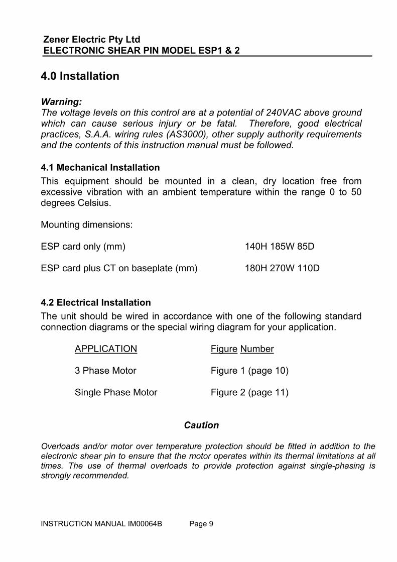
4.0 Installation Warning: The voltage levels on this control are at a potential of 240VAC above ground which can cause serious injury or be fatal. Therefore, good electrical practices, S.A.A. wiring rules (AS3000), other supply authority requirements and the contents of this instruction manual must be followed.
4.1 Mechanical Installation This equipment should be mounted in a clean, dry location free from excessive vibration with an ambient temperature within the range 0 to 50 degrees Celsius. Mounting dimensions: ESP card only (mm) 140H 185W 85D ESP card plus CT on baseplate (mm) 180H 270W 110D
4.2 Electrical Installation The unit should be wired in accordance with one of the following standard connection diagrams or the special wiring diagram for your application. APPLICATION Figure Number 3 Phase Motor Figure 1 (page 10) Single Phase Motor Figure 2 (page 11)
Caution
Overloads and/or motor over temperature protection should be fitted in addition to the electronic shear pin to ensure that the motor operates within its thermal limitations at all times. The use of thermal overloads to provide protection against single-phasing is strongly recommended.

Zener Electric Pty Ltd ELECTRONIC SHEAR PIN MODEL ESP1 & 2
INSTRUCTION MANUAL IM00064B Page 10
Figure 1: Typical Connection for 3 phase motors Notes: 1) Remote reset optional; for automatic reset use a N/O contact of M 2) CT (see Table 1) must be fitted to motor phase connected to terminal L1 3) See section 3.0 for set up procedure of range selector switch SWA 4) Area enclosed by dotted line is only applicable to ESP 2
Zener Electric Pty Ltd ELECTRONIC SHEAR PIN MODEL ESP1 & 2
INSTRUCTION MANUAL IM00064B Page 11
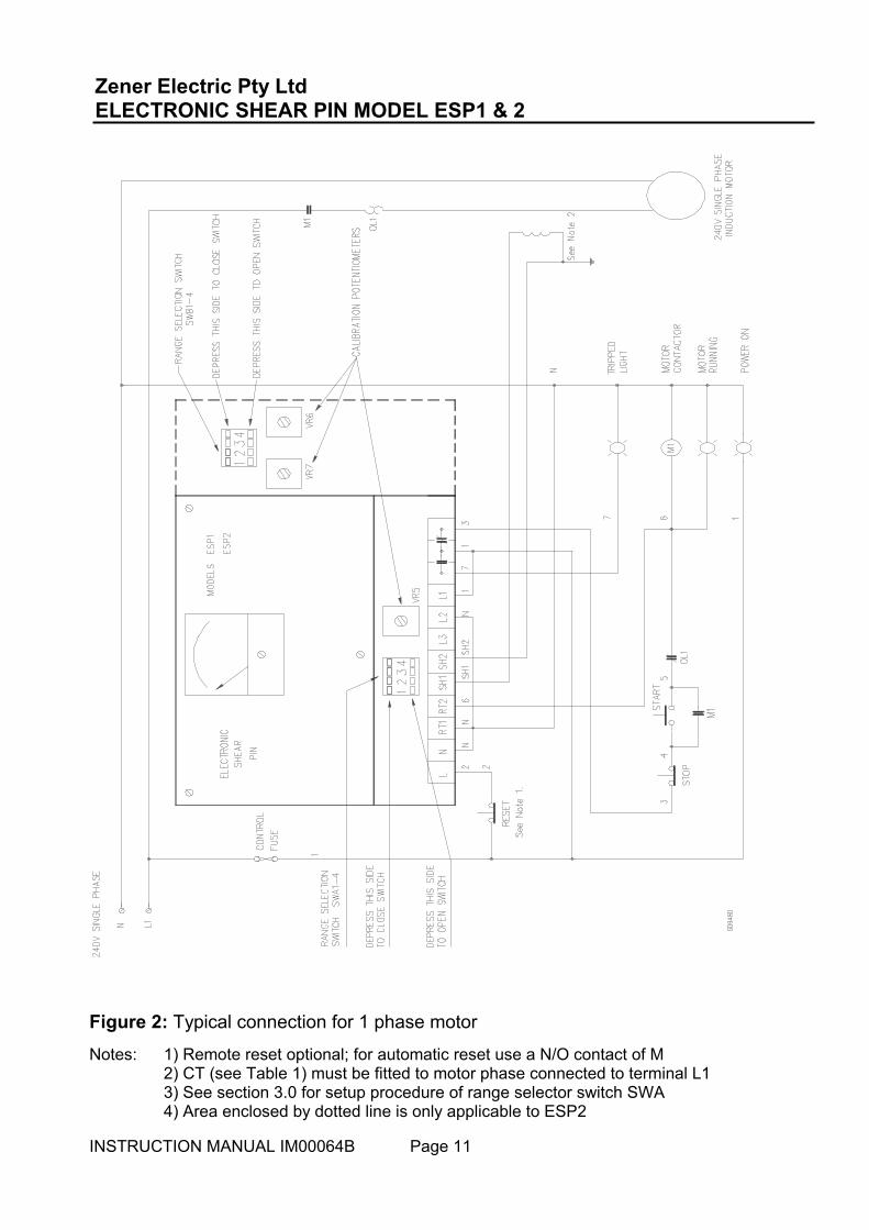
Figure 2: Typical connection for 1 phase motor
Notes: 1) Remote reset optional; for automatic reset use a N/O contact of M 2) CT (see Table 1) must be fitted to motor phase connected to terminal L1 3) See section 3.0 for setup procedure of range selector switch SWA 4) Area enclosed by dotted line is only applicable to ESP2

Zener Electric Pty Ltd ELECTRONIC SHEAR PIN MODEL ESP1 & 2
INSTRUCTION MANUAL IM00064B Page 12
Figure 3: Current Transformer Model 701 connection diagram

Zener Electric Pty Ltd ELECTRONIC SHEAR PIN MODEL ESP1 & 2
INSTRUCTION MANUAL IM00064B Page 13
5.0 Commissioning
5.1 Setting up The procedure below details the method to be followed to set the various adjustments on the Electronic Shear Pin to working positions. If you do not know the normal running conditions for the motor to be protected by the Electronic Shear Pin, the following may be a useful guide for initial set up figures which could be modified in the light of experience with the particular installation. Stage 1: Set the START TIME to about 50% (to give about 10 seconds starting time). Stage 2: Set the SET POINT adjustment fully clockwise. Stage 3: Set the TRIP DELAY adjustment to about 50% of it's travel (to give about 6 seconds trip delay time). Stage 4: Ensure that the current transformer and range selection switch positions have been correctly selected in accordance with section 3.0 of this manual. Stage 5 (ESP 2 Only): Ensure that the motor voltage and phase loss/under voltage trip options have been correctly selected in accordance with section 3.0 on Page 8. Stage 6: With power applied to the system, but the motor not running, observe that the green POWER ON indicator is illuminated. Stage 7: Press the TEST switch (located on the left side of the unit) down to the SET position and set the adjacent TEST LOAD adjustment to give an indication on the meter corresponding to the desired trip point. Stage 8: With the TEST switch still in the SET position, rotate the SET POINT adjustment counter-clockwise to just cause the associated yellow indicator to light. Stage 9: Release the TEST switch and observe that the SET POINT indicator light goes out. Stage 10: Press the TEST switch to the SET position again and observe that the SET POINT indicator lights and, after a short delay, the red TRIP DELAY light also comes on.

Zener Electric Pty Ltd ELECTRONIC SHEAR PIN MODEL ESP1 & 2
INSTRUCTION MANUAL IM00064B Page 14
Stage 11: Rotate the TRIP DELAY adjustment and repeat previous step until the desired trip delay is achieved. Stage 12: Isolate the motor from it's supply. Do not remove power from terminals L1, L2 or L3 (L1 or L2 for single phase motors). Turning off the motor at it's local isolator switch is suitable. Stage 13: Energise the motor contactor by pressing the motor start button (this provides power to terminals RT1 and RT2) and observe that the START TIME indicator lights for a short time (about 6 seconds). The Electronic Shear Pin will not be tripped by the high starting currents of the motor during the start time. Stage 14: Press the motor stop button to reset the start timer. Stage 15: Rotate the START TIME adjustment (clockwise will give a longer time) and repeat the previous two steps until the desired start time is achieved. If the start time is set too short, the ESP 1 may trip and it will be necessary to press the RESET switch before proceeding. Stage 16: Re-connect the motor. Calibration of the ESP is now complete.
5.2 Functional Test With the motor running, the trip system may be tested as follows: Stage 1: Press the TEST switch (located on the left hand side of the unit) down to the SET position. Rotate the TEST LOAD adjustment to give a meter indication of the load value that you wish to simulate. Stage 2: Press the TEST switch upwards into the TRIP position and, provided the load you have simulated exceeds the SET POINT, the unit will trip after the TRIP DELAY time disconnecting the motor from its supply. Stage 3:The unit may be reset by operating the external reset button (if fitted) or by depressing the RESET switch located on the right hand side of the unit.

Zener Electric Pty Ltd ELECTRONIC SHEAR PIN MODEL ESP1 & 2
INSTRUCTION MANUAL IM00064B Page 15
6.0 Operation The Electronic Shear Pin, being fully automatic, requires no attention during normal operation. Should an overload occur and the unit trip, disconnecting the motor, operation may be restored by removing the cause of the overload, resetting the unit by means of either the RESET switch on the unit or an external reset button and then re-starting the motor.
7.0 Maintenance The Electronic Shear Pin requires no regular maintenance other than to occasionally check for oil and/or dust build-up which should be removed with a suitable FREON based aerosol cleaner. Also, check that all terminals are tight. However, should you wish to confirm or check the internal calibration of the unit proceed as follows:
7.1 Load Measurement Calibration Stage 1: Set all contacts of switch A to the "on" (closed) position. Stage 2: Connect a 240VAC single phase supply to terminals L and L1 (active) and to N and L2 (neutral). Stage 3: Apply a current of exactly 4.0A RMS to terminals SH1 and SH2 (in phase with the voltage applied to L1 and L2) and adjust the calibration potentiometer (located adjacent to the range selection switches) to cause the % MOTOR LOAD meter to read 100%.
7.2 Phase Loss/under voltage Trip Calibration (ESP 2 Only) Note: A high input impedance meter (> 10 MΩ) must be used. Stage 1: Set SWB-1, SWB-3 and SWB-4 to the off (open) position. Set SWB-2 to the on (closed) position. Stage 2: Connect a 240Vac single phase supply to terminals L (active) and to N (neutral).

Zener Electric Pty Ltd ELECTRONIC SHEAR PIN MODEL ESP1 & 2
INSTRUCTION MANUAL IM00064B Page 16
Stage 3: Connect an adjustable voltage (around 240Vac) single phase supply to terminals L1 (active) and to L2 (neutral). Start with this voltage at 240Vac and decrease until the trip relay RL1 operates and the trip light flashes. If this does not occur at about 194Vac, adjust VR7 slightly and re-test. Stage 4: After successful completion of stage 3, measure the voltage at the test point TP2 (pin 10 of IC6) when RL1 has just operated. It should be approximately +4.7Vdc. Terminal SH1 is common. Stage 5: Close SWB-1 and, without altering the input test voltage, adjust VR6 to reduce the voltage measured in stage 4 by a factor of 2.66. Example: If +4.7Vdc was measured in stage 4, adjust VR6 for 1.77Vdc: 4.7/2.66 = 1.77Vdc Procedure complete..

DELIVERY ADDRESS 366 Horsley Road MILPERRA NSW 2214 AUSTRALIA
POSTAL ADDRESS PO Box 4462 MILPERRA DC NSW 1891 AUSTRALIA
Tel: +61-2-9795 3600 Fax: +61-2-9795 3611 Email: [email protected]