electronic speed controller for bldc and pmsm three … · electronic speed controller for bldc and...
TRANSCRIPT

April 2017 DocID030508 Rev 1 1/29
www.st.com
UM2197 User manual
Electronic speed controller for BLDC and PMSM three phase brushless motor
Introduction The STEVAL-ESC001V1 evaluation board is based on the STM32F303 microcontroller, L6398 driver and STL160NS3LLH7 power MOSFETs. It is an electronic speed controller (ESC) designed to drive a single three phase brushless motor (BLDC/PMSM), performing a sensorless FOC algorithm with speed regulation and active braking function. This unit can accept commands from an external unit for driving and monitoring a flight control board, for instance. For this purpose, several communication bus interfaces (UART, CAN, I²C) are available.
The board includes a BEC 5 V circuit and embeds an overcurrent/overvoltage and thermal protection circuit. Its form factor renders it suitable for small and light R/C vehicles and its motor current capability meets the power requirements of larger vehicles like professional drones.
Figure 1: STEVAL-ESC001V1 evaluation board

Contents UM2197
2/29 DocID030508 Rev 1
Contents
1 Main features ................................................................................... 5
1.1 Target application .............................................................................. 5
2 Description....................................................................................... 6
2.1 STEVAL-ESC001V1 hardware overview .......................................... 8
2.1.1 STEVAL-ESC001V1 top side components ........................................ 8
2.1.2 STEVAL-ESC001V1 bottom side components .................................. 9
2.1.3 Board dimensions (29.1 x 58 mm) ................................................... 10
2.2 Communication, programming and command interfaces ................ 10
2.3 STM32 pinout for motor control ....................................................... 11
3 Initializing and using the STEVAL-ESC001V1 ESC board .......... 13
4 Schematic diagrams ...................................................................... 19
5 Bill of materials .............................................................................. 23
6 Revision history ............................................................................ 28

UM2197 List of tables
DocID030508 Rev 1 3/29
List of tables
Table 1: Main STM32 pinout for motor control ......................................................................................... 11 Table 2: Input/output terminals ................................................................................................................. 12 Table 3: Relationship between the STEVAL board SWD pinout and SWD on ST-Link/V2 programmer . 13 Table 4: Document revision history .......................................................................................................... 28

List of figures UM2197
4/29 DocID030508 Rev 1
List of figures
Figure 1: STEVAL-ESC001V1 evaluation board ........................................................................................ 1 Figure 2: STEVAL-ESC001V1 target applications ..................................................................................... 5 Figure 3: System structure overview .......................................................................................................... 7 Figure 4: Typical quadcopter architecture .................................................................................................. 7 Figure 5: STEVAL-ESC001V1 block diagram ............................................................................................ 8 Figure 6: Top side features ......................................................................................................................... 8 Figure 7: Bottom side features .................................................................................................................. 10 Figure 8: STEVAL-ESC001V1 board dimensions (not including capacitors) ........................................... 10 Figure 9: UART TX/RX (3v3 level) ............................................................................................................ 11 Figure 10: STEVAL-ESC001V1 connection for MCU programming ........................................................ 13 Figure 11: Sample SWD configuration on IAR tool .................................................................................. 14 Figure 12: STEVAL-ESC001V1 input/output connection ......................................................................... 15 Figure 13: ST MC Workbench .................................................................................................................. 15 Figure 14: ST MC Workbench – electrical motor parameters .................................................................. 16 Figure 15: ST MC Workbench – startup parameters ................................................................................ 17 Figure 16: IAR tool select, compile and upload ........................................................................................ 18 Figure 17: PWM input signal for motor speed regulation ......................................................................... 18 Figure 18: STEVAL-ESC001V1 ciruit schematic (1 of 4) ......................................................................... 19 Figure 19: STEVAL-ESC001V1 ciruit schematic (2 of 4) ......................................................................... 20 Figure 20: STEVAL-ESC001V1 ciruit schematic (3 of 4) ......................................................................... 21 Figure 21: STEVAL-ESC001V1 ciruit schematic (4 of 4) ......................................................................... 22

UM2197 Main features
DocID030508 Rev 1 5/29
1 Main features
3 phase driver board for BLDC/PMSM motors with discrete N-channel 30 V, 160 A STripFET™ H7 Power MOSFETs
48-pin STM32 with FPU ARM® Cortex®-M4 MCU with 128 Kbytes Flash, 72 MHz CPU, MPU, CCM, 12-bit ADC 5 MSPS, PGA, comparators
Nominal operating voltage range: 3S-6S Li-Po battery DC voltage level (11.1 V up to 22.2 V)
Maximum RMS output current: 20 Arms
Output peak current: 30 A
BEC available (5 V, 0.5 A for supplying external board; e.g., flight control board)
Designed for field oriented control (FOC) in sensorless mode
Supported by ST motor control software development kit (SDK)
Ready to use with ST motor profiler
3-shunt mode supported for motor current sensing
Cross conduction protection based on L6398 driver
Overcurrent and overvoltage protection feature (OCP/OVP)
Thermal measuring and overheating protection with on-board NTC
Horizontal bus capacitors for low profile
CAN, UART, I²C, SWD and PWM connectors available
Fully populated board conception with test points for DAC, GPIOs, PWM signals, motor current feedback and CAN
User LEDs (green and red)
Target applications: motor driving for R/C vehicles, UAV drone, electric car etc.
PCB type and size:
PCB material: FR-4
Multi-layer architecture
Dimensions: 29.1 mm x 58 mm
RoHS compliant
1.1 Target application
Motor driving for remote control vehicles, UAV drones, electrical cars and boats, etc.
Figure 2: STEVAL-ESC001V1 target applications

Description UM2197
6/29 DocID030508 Rev 1
2 Description
The STEVAL-ESC001V1 electronic speed controller (ESC) evaluation board drives a single three phase brushless motor with very high performance in sensorless mode (without position sensor).
It is designed to provide fast and efficient propulsion for remote control applications like electric cars, boats and drones and is capable of low and very high speed regulation and strong dynamic response under different load conditions.
An external signal via a communication bus between the board and a generic central unit sets the speed regulation reference and another signal reports the status of the system, including faults, which the central unit can use to trigger corrective events.
The same 6Step (or trapezoidal) control algorithm (often with no shunt resistors) drives the many different ESCs offering various motor current, size and input voltages for remote control applications.
A more sophisticated control algorithm is used in the STEVAL-ESC001V1, based on field oriented control (FOC); it features:
better torque control
motor current regulation in case of fast load change
vibration reduction
active braking function
better efficiency
noise reduction
a real-time monitor of the rotor speed
energy recovery during the deceleration
The typical system architecture pictured below shows individual ESC boards connected to single brushless motors in a quadcopter system. An external Li-Po battery powers the four boards and a wired bus carries communication between each board and an external unit such as a flight control board.

UM2197 Description
DocID030508 Rev 1 7/29
Figure 3: System structure overview
Figure 4: Typical quadcopter architecture
Description UM2197
8/29 DocID030508 Rev 1
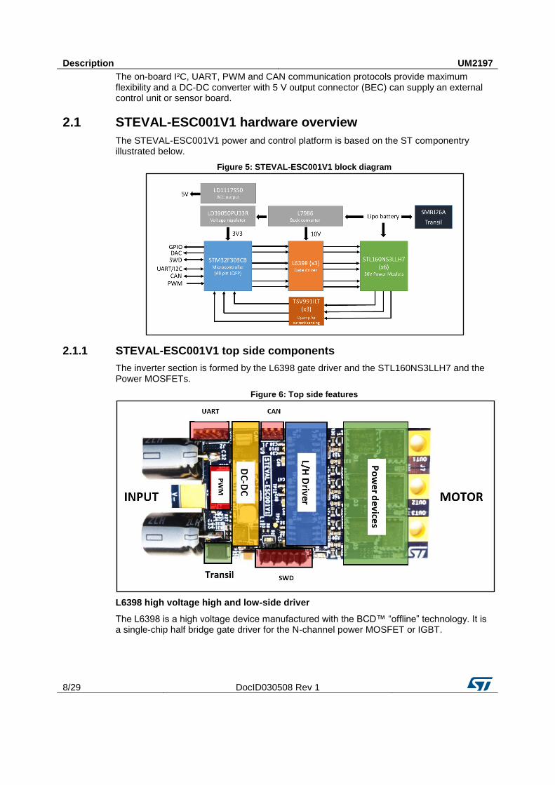
The on-board I²C, UART, PWM and CAN communication protocols provide maximum flexibility and a DC-DC converter with 5 V output connector (BEC) can supply an external control unit or sensor board.
2.1 STEVAL-ESC001V1 hardware overview
The STEVAL-ESC001V1 power and control platform is based on the ST componentry illustrated below.
Figure 5: STEVAL-ESC001V1 block diagram
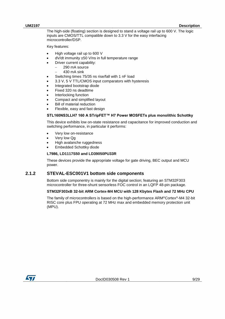
2.1.1 STEVAL-ESC001V1 top side components
The inverter section is formed by the L6398 gate driver and the STL160NS3LLH7 and the Power MOSFETs.
Figure 6: Top side features
L6398 high voltage high and low-side driver
The L6398 is a high voltage device manufactured with the BCD™ “offline” technology. It is a single-chip half bridge gate driver for the N-channel power MOSFET or IGBT.
UM2197 Description
DocID030508 Rev 1 9/29
The high-side (floating) section is designed to stand a voltage rail up to 600 V. The logic inputs are CMOS/TTL compatible down to 3.3 V for the easy interfacing microcontroller/DSP.
Key features:
High voltage rail up to 600 V
dV/dt immunity ±50 V/ns in full temperature range
Driver current capability:
290 mA source
430 mA sink
Switching times 75/35 ns rise/fall with 1 nF load
3.3 V, 5 V TTL/CMOS input comparators with hysteresis
Integrated bootstrap diode
Fixed 320 ns deadtime
Interlocking function
Compact and simplified layout
Bill of material reduction
Flexible, easy and fast design
STL160NS3LLH7 160 A STripFET™ H7 Power MOSFETs plus monolithic Schottky
This device exhibits low on-state resistance and capacitance for improved conduction and switching performance, in particular it performs:
Very low on-resistance
Very low Qg
High avalanche ruggedness
Embedded Schottky diode
L7986, LD1117S50 and LD39050PU33R
These devices provide the appropriate voltage for gate driving, BEC output and MCU power.
2.1.2 STEVAL-ESC001V1 bottom side components
Bottom side componentry is mainly for the digital section; featuring an STM32F303 microcontroller for three-shunt sensorless FOC control in an LQFP 48-pin package.
STM32F303xB 32-bit ARM Cortex-M4 MCU with 128 Kbytes Flash and 72 MHz CPU
The family of microcontrollers is based on the high-performance ARM®Cortex®-M4 32-bit RISC core plus FPU operating at 72 MHz max and embedded memory protection unit (MPU).

Description UM2197
10/29 DocID030508 Rev 1
Figure 7: Bottom side features
2.1.3 Board dimensions (29.1 x 58 mm)
Figure 8: STEVAL-ESC001V1 board dimensions (not including capacitors)
2.2 Communication, programming and command interfaces
The STEVAL-ESC001 features these communication interfaces:
CAN port (J1): comes with an on-board transceiver; the J1 connector includes 3V3 and GND pins.
UART/I²C port (J2): normally used for serial communication between the ESC board and a PC; ST MC Workbench can be connected with the STM32, adding an external circuit (requires USB/RS232 converter-3v3 level)

UM2197 Description
DocID030508 Rev 1 11/29
Figure 9: UART TX/RX (3v3 level)
PWM signal input (J3): connects with an external board (e.g., flight control unit), to receive commands; the signal level (at 3v3) sets the motor speed according to the Ton duration (i.e., 1060 µs for min. speed and 1860 µs for max. speed). Other pins are for GND and a +5Vdc power line to supply an external board
SWD debug port (J4): provides the SWD connection between the STM32 and ST-LINK programmer; other pins like 3V3 and GND are available.
2.3 STM32 pinout for motor control
Table 1: Main STM32 pinout for motor control
Pin Default Signal Solder Bridge
1 VBAT 3V3
2 PC13/TAMP/RTC TP4
3 PC14 N.C.
4 PC15 N.C.
5 PF0/OSC-IN OSC 8Mhz
6 PF1/OSC-OUT OSC 8Mhz R4
7 NRST RESET
8 VSSA/VREF- GND
9 VDDA/VREF+ 3V3
10 PA0-WKUP Curr_fdbk1
11 PA1 Curr_fdbk2
12 PA2 Curr_fdbk3
13 PA3 Temperature feedback
14 PA4 VREF, DAC1, TP8 R6 N.M.
15 PA5 DAC2, TP9
16 PA6 N.C.
17 PA7 Vshunt_1_filtered
18 PB0 Vshunt_2_filtered
19 PB1 TIM1_CH3N
20 PB2 STATUS
21 PB10 N.C.
22 PB11 Vshunt_3_filtered
23 VSS1 GND
Description UM2197
12/29 DocID030508 Rev 1
Pin Default Signal Solder Bridge
24 VDD1 3V3
25 PB12 PHASE_1
26 PB13 VBUS R5
27 PB14 PHASE_2
28 PB15 PHASE_3
29 PA8 TIM1_CH1
30 PA9 TIM1_CH2 R51
31 PA10 TIM1_CH3
32 PA11 TIM1_CH1N
33 PA12 TIM1_CH2N
34 PA13 SWDIO
35 VSS2 GND
36 VDD2 3V3
37 PA14 SWCLK
38 PA15 INPUT
39 PB3 N.C.
40 PB4 TP3
41 PB5 N.C.
42 PB6 USART1_TX/I2C1_SCL
43 PB7 USART1_RX/I2C1_SDA
44 BOOT0 BOOT0 R3
45 PB8 CAN_RX
46 PB9 CAN_TX
47 VSS
48 VDD
Table 2: Input/output terminals
Screw Terminal Function
J5/J6 Li-Po battery power input (3S-6S)
J7 3-PH Motor connector
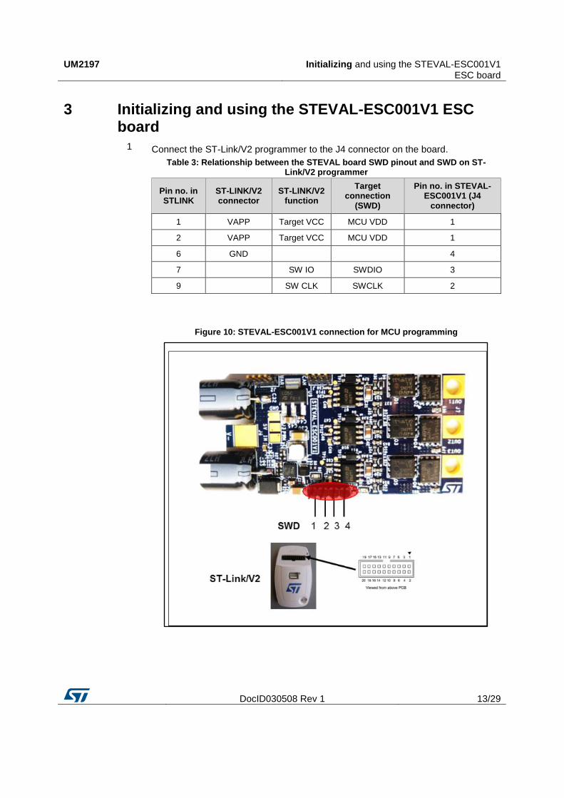
UM2197 Initializing and using the STEVAL-ESC001V1 ESC board
DocID030508 Rev 1 13/29
3 Initializing and using the STEVAL-ESC001V1 ESC board
1 Connect the ST-Link/V2 programmer to the J4 connector on the board.
Table 3: Relationship between the STEVAL board SWD pinout and SWD on ST-Link/V2 programmer
Pin no. in STLINK
ST-LINK/V2 connector
ST-LINK/V2 function
Target connection
(SWD)
Pin no. in STEVAL-ESC001V1 (J4
connector)
1 VAPP Target VCC MCU VDD 1
2 VAPP Target VCC MCU VDD 1
6 GND
4
7
SW IO SWDIO 3
9
SW CLK SWCLK 2
Figure 10: STEVAL-ESC001V1 connection for MCU programming

Initializing and using the STEVAL-ESC001V1 ESC board
UM2197
14/29 DocID030508 Rev 1
2 Set the SWD interface in the IDE tool
Figure 11: Sample SWD configuration on IAR tool
3 Solder the three motor wires U,V,W at the motor connector with no particular color sequence.
As shown in Figure 12: "STEVAL-ESC001V1 input/output connection", the right side is for the motor connection with three pads provided for soldering.
4 Solder the PWM input at J3 connector.
The INPUT pin level must not exceed 3V3.

UM2197 Initializing and using the STEVAL-ESC001V1 ESC board
DocID030508 Rev 1 15/29
5 Connect the STEVAL-ESC001V1 with a Li-Po battery (or DC power supply: min 3S – max 6S) with the right polarity and turn ON.
The input connector has two large pads for soldering: the top layer for GND and bottom for Vdc+. A transil device prevents damage in case of reverse polarity.
Figure 12: STEVAL-ESC001V1 input/output connection
6 Verify if the green led is turned on.
7 Open ST MC
Figure 13: ST MC Workbench

Initializing and using the STEVAL-ESC001V1 ESC board
UM2197
16/29 DocID030508 Rev 1
8 Fill in the motor parameters
Figure 14: ST MC Workbench – electrical motor parameters
UM2197 Initializing and using the STEVAL-ESC001V1 ESC board
DocID030508 Rev 1 17/29
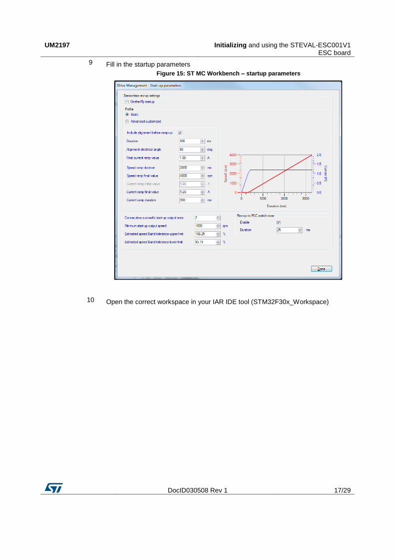
9 Fill in the startup parameters
Figure 15: ST MC Workbench – startup parameters
10 Open the correct workspace in your IAR IDE tool (STM32F30x_Workspace)

Initializing and using the STEVAL-ESC001V1 ESC board
UM2197
18/29 DocID030508 Rev 1
11 Select the STM32303C-EVAL_SINGLEDRIVE project configuration (blue arrow), compile the source code and upload the binary to the MCU (red arrow)
Figure 16: IAR tool select, compile and upload
12 Generate a PWM signal at 490 Hz and duty cycle between 1060 µs and 1860 µs
The ESC is not armed (no driving signals generated) if the duty cycle is lower than 1060 µs.
If the motor is already started, a blank time of 1500 ms on the PWM signal switches the system off (ESC turned OFF).
Figure 17: PWM input signal for motor speed regulation
13 The motor starts to rotate between the minimum and maximum speed.

UM2197 Schematic diagrams
DocID030508 Rev 1 19/29
4 Schematic diagrams Figure 18: STEVAL-ESC001V1 ciruit schematic (1 of 4)
CAN_RX
CAN_TX
+3.3V
+3.3V
+3.3V
+3v3
V-
J1CAN
1234
R2120
C1100nF
U1
SN65HVD230
D1
GND2
VCC3
R4
VREF5CANL6CANH7RS8
R10
TP1
CAN_TX
1
TP2
CAN_RX1

Schematic diagrams UM2197
20/29 DocID030508 Rev 1
Figure 19: STEVAL-ESC001V1 ciruit schematic (2 of 4)
PP
M fro
m F
C u
nit
US
AR
T1
_R
X/I2
C1
_S
DA
US
AR
T1
_T
X/I2
C1
_S
CL
CA
N_
RX
CA
N_
TX
SW
CL
K
INP
UT
US
AR
T1
_R
X/I2
C1
_S
DA
US
AR
T1
_T
X/I2
C1
_S
CL
SW
CL
KS
WD
IO
SW
DIO
INP
UT
+3
.3V
+3
.3V
+3
.3V
+3
.3V +
3.3
V
+3
.3V
+3
.3V
+3
.3V
TIM
1_
CH
2N
PH
AS
E_
1
PH
AS
E_
2P
HA
SE
_3
VB
US
VR
EF
TIM1_CH3N
TIM
1_
CH
1T
IM1
_C
H2
TIM
1_
CH
3
ST
AT
US
+3
v3
TIM
1_
CH
1N
V-
Cu
rr_fd
bk3
Vshunt_1_filteredVshunt_2_filtered
Vshunt_3_filtered
Cu
rr_fd
bk2
Cu
rr_fd
bk1
Te
mp
era
ture
fee
db
ack
+5
V
ST
AT
US
R4
22
0
C1
31
00
nF
R7
51
0
TP
5P
hU
1
J4
SW
D1 2 3 4
R5
0
D1
RE
D
C6
4.7
u
TP
4
1
TP
3 GP
IO11
C1
01
00
nF
C1
11
nF
C2
10
0n
F
R3
10
k
C3
1n
FC
41
nF
TP
6P
hV
1
TP
8
DAC_OUT
1
C7
10
nF
J2
UA
RT
1 2 3 4
U2
ST
M3
2F
30
3C
BT
7
PA414
PA515
PA616
PA717
PB220
PB1021
PB1122
VSS123
PB541 PB642 PB743 BOOT044 PB845 PB946
PB
13
26
PB
14
27
PB
15
28
PA
82
9P
A9
30
PA
12
33
PA
13
34
VS
S2
35
VD
D2
36
PC
14
3
PC
15
4
PF
0/O
SC
-IN5
PF
1/O
SC
-OU
T6
NR
ST
7
VB
AT
1
PA
21
2
PA
10
31
VSS47
PA313
PA
11
32
VDD48
PC
13
/TA
MP
/RT
C2
VS
SA
/VR
EF
-8
VD
DA
/VR
EF
+9
PA
0-W
KU
P1
0
PA
11
1
PB018
PB119
VDD124
PB
12
25
PA1437 PA1538 PB339 PB440
R8
51
0
TP
7P
hW
1
J3
PW
MIN
PU
T1 2 3
C9
1u
F
X1
8M
Hz
TP
9
DAC_OUT2
1
C5
10
0n
F
R6
0N
.M
D2
GR
EE
N
C8
10
0n
F
C1
21
00
nF
PA
12
-VL
PB
13
-B
US
V
GN
D
GN
D
PB1-WL
PA
8-U
HP
A9
-VH
PA
10
-WH
PA
11
-UL
PA
2-
Ph
WP
A1
-P
hV
PA
0-
Ph
U

UM2197 Schematic diagrams
DocID030508 Rev 1 21/29
Figure 20: STEVAL-ESC001V1 ciruit schematic (3 of 4)
for
inte
rnal com
para
tor
OC
P c
ircuit
Vsh
unt_
3_G
ND
Vsh
unt_
2_G
ND
Vsh
unt_
1_G
ND
Ext
ern
al o
p-a
mp
0.5
V
3V
3
3V
3
3V
3
3V
33
V3
3V
3
3V
3
3V
3
Vsh
un
t_1
Vsh
un
t_2
_filte
red
Vsh
un
t_2
Vsh
un
t_3
_filte
red
Vsh
un
t_3
Vsh
un
t_1
_filte
red
VR
EF
V-
Vsh
un
t_1
Cu
rr_
fdb
k1
Cu
rr_
fdb
k2
Vsh
un
t_2
Cu
rr_
fdb
k3
Vsh
un
t_3
+3
v3
C1
8
10
0n
F
C1
41
00
nF
R2
13
.4k
1%
R2
23
.4k
1%
-+
U5
TS
V9
91
ILT
3
2
14
5
C2
6N
.M.1
00
pF
C1
9
10
0n
F
C1
61
5n
F6
.3V
R2
51
3k
1%
R2
0 78
7
R1
97
87
R1
26
80
R1
16
80
R1
7 78
7
R1
48
06
01
%R
16
80
60
1%
R1
58
06
01
%
R1
06
80
R1
83
.4k
1%
R2
41
3k
1%
R1
35
.9K
C2
5N
.M.1
00
pF
-+
U3
TS
V9
91
ILT
3
2
14
5
C2
2
68
0p
F1
0V
C2
1
68
0p
F1
0V
C2
3
10
0n
F
-+
U4
TS
V9
91
ILT
3
2
14
5
C1
71
5n
F6
.3V
R2
31
3k
1%
C2
0
68
0p
F1
0V
C2
4N
.M.1
00
pF
C1
51
5n
F6
.3V
R9
33
K

Schematic diagrams UM2197
22/29 DocID030508 Rev 1
Figure 21: STEVAL-ESC001V1 ciruit schematic (4 of 4)
VBU
S
PO
WER S
EC
TIO
N
SH
UN
T R
ESIS
TO
R
AU
X P
OW
ER S
UPPL
Y
BEC
5V, 0
.5A PH
ASE S
EN
SIN
G C
IRC
UI
T
smal
l sig
nal
LPS4
018-
333M
R Coilc
raft
33uH
/0.5
A38Vm
ax
1MH
z
0.5
A
DN
G_
3_
tn
uh
sV
DN
G_
2_
tn
uh
sV
Vsh
unt_
1_G
ND
VIN
+
VBU
S
Vsh
unt
_1
Vsh
unt
_2
Vsh
unt
_3
+5V
VIN
+
TIM
1_C
H2
TIM
1_C
H2N
TIM
1_C
H3
TIM
1_C
H3N
TIM
1_C
H1
TIM
1_C
H1N
+10V +10V +10V
Vsh
unt
_2
V+
+5V
Vsh
unt
_1
Vsh
unt
_3
PH
AS
E_2
PH
AS
E_3
PH
AS
E_1
V-
+10V
+3v3
V+
+10V
+3v3
V-
Tem
per
atu
re feedbac
k
+3v3
C49
470nF
X7R
D9
BAT30KF
ILM
R66
0.0
10
3W
R37
100
D11
STP
S0560Z
12
R56
4.0
2k1%
C50
1uF
X7R
U9
LD
1117S
50T
R
Vo
ut
2
GN
D
1
Vin
3
C36
27pF
D4
STP
S0560Z
12
J6 CO
N1
1
R36
1
R31
300
1%
C29
10uF
,50V
+C35
330uF
,35V
C47
100pF
R27
62
R59
100
C45
10uF
TP
14
TP
CH
3
1
Q1
STL160N
S3LLH
7
R46
1
R33
100
TP
13
TP
CH
2N
1
R67
0.0
10
3W
R35
56
C53
100pF
R52
33k
1%
TP
11
TP
CH
1N
1
U7
L6398D
TR
LIN
1
HIN
2
VC
C3
GN
D4
LV
G5
OU
T6
HV
G7
BO
OT
8
R65
4.7
k
Q2
STL160N
S3LLH
7
C40
470nF
X7R
R58
1
R29
34.
8k
1%
R62
169K
1%
C27
3.9
nF
C37
4.7
nF
R55
56
C46
1uF
R34
10k
C48
100pF
TP
12
TP
CH
2
1
Q6
STL160N
S3LLH
7
R30
56
C56
100nF
C42
1uF
X7R
L1
33uH
C38
100pF
C41
10nF
R38
10k
J7Moto
r
123
R45
100
R26
4.7
k1%
R50
100
R68
18K
1%
C51
10nF
C44
100nF
C34
100nF
100V
R61
10k
D6
BAT30KF
ILM
D7
BAT30KF
ILM
C58
10nF
R39 0
C31
1uF
X7R
Q4
STL160N
S3LLH
7
C39
100pF
R53
33k
1%
R57
4.0
2k1%
D13
BAT30KF
ILM
C57
100nF
TP
10TP
CH
1
1
R44
56
Q5
STL160N
S3LLH
7
C33
100nF
100V
R49
56
R54
33k
1%
R28 0
D5
SM
BJ2
6A-
TR
R42
100
R63
NTC
10K
21
R47
10k
U11
L6398D
TR
LIN
1
HIN
2
VC
C3
GN
D4
LV
G5
OU
T6
HV
G7
BO
OT
8
+
C32
330uF
,35V
C55
100nFR
41
0
C43
1uF
D10
BAT30KF
ILM
C28
220nF
D14
BAT30KF
ILM
R51
10k
R40
56
D12
BAT30KF
ILM
U8
LD
39050PU
33R
PG
3E
N1
VIN
6N
C5
VO
UT
4
GN
D1
2
GN
D
7
Q3
STL160N
S3LLH
7
D8
STP
S0560Z
12
R48
0
R64
0.0
10
3W
C54
470nF
X7R
C52
100pF
C60
4.7
nF10V
U6
L7986T
R
OU
T2
2
Fsw
7
GN
D8
FB
6
EN
4
CO
MP
5
SY
NC
3
VC
C9
9
EP
11
VC
C10
10
OU
T1
1
R60
4.0
2k1%
R32
8.2
k
D3
STP
S1L40M
12
J5 CO
N1
1
U10
L6398D
TR
LIN
1
HIN
2
VC
C3
GN
D4
LV
G5
OU
T6
HV
G7
BO
OT
8
TP
15
TP
CH
3N
1
C30
22uF
25V
C59
10nF
10V
R43
10k
OU
T1
VBU
S_S
ENS
OU
T1
OU
T3
OU
T2
OU
T3
OU
T2
UM2197 Bill of materials
DocID030508 Rev 1 23/29
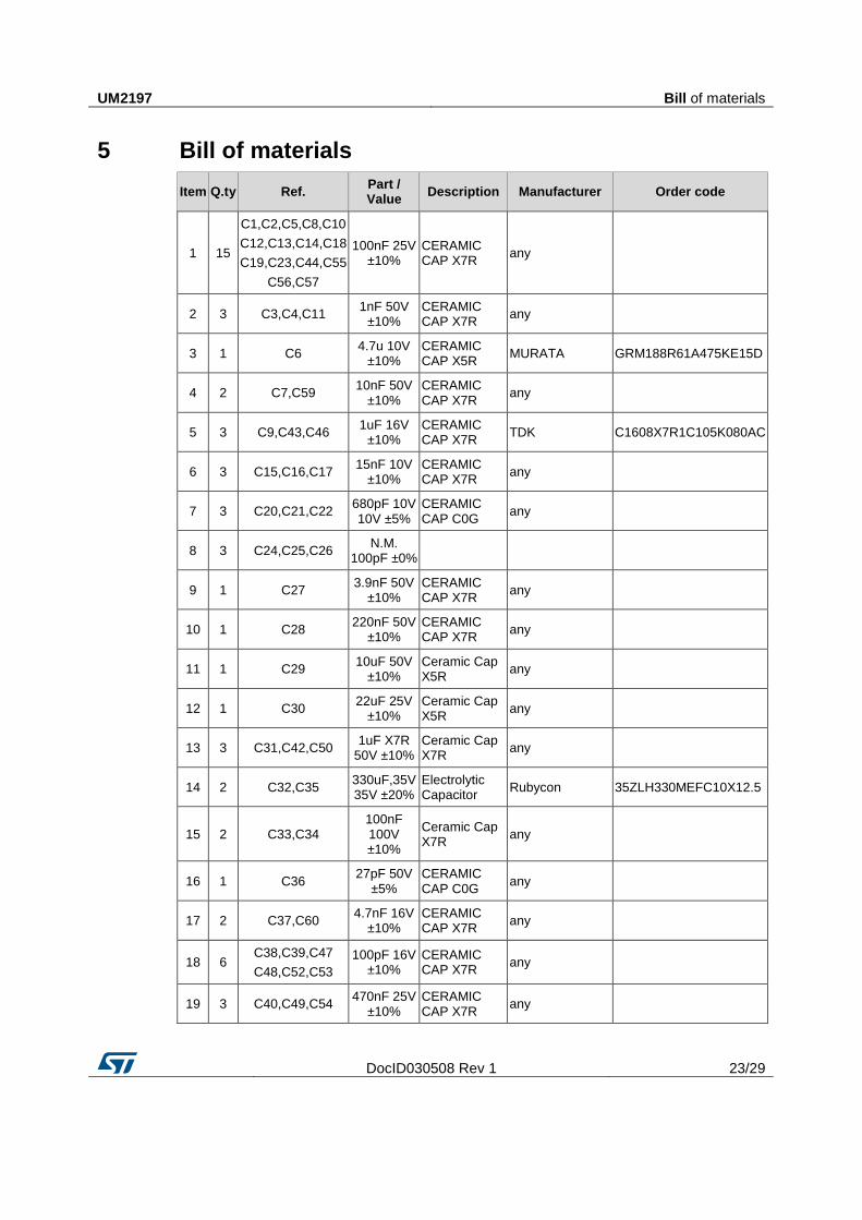
5 Bill of materials
Item Q.ty Ref. Part / Value
Description Manufacturer Order code
1 15
C1,C2,C5,C8,C10
C12,C13,C14,C18
C19,C23,C44,C55
C56,C57
100nF 25V ±10%
CERAMIC CAP X7R
any
2 3 C3,C4,C11 1nF 50V
±10% CERAMIC CAP X7R
any
3 1 C6 4.7u 10V
±10% CERAMIC CAP X5R
MURATA GRM188R61A475KE15D
4 2 C7,C59 10nF 50V
±10% CERAMIC CAP X7R
any
5 3 C9,C43,C46 1uF 16V
±10% CERAMIC CAP X7R
TDK C1608X7R1C105K080AC
6 3 C15,C16,C17 15nF 10V
±10% CERAMIC CAP X7R
any
7 3 C20,C21,C22 680pF 10V 10V ±5%
CERAMIC CAP C0G
any
8 3 C24,C25,C26 N.M.
100pF ±0%
9 1 C27 3.9nF 50V
±10% CERAMIC CAP X7R
any
10 1 C28 220nF 50V
±10% CERAMIC CAP X7R
any
11 1 C29 10uF 50V
±10% Ceramic Cap X5R
any
12 1 C30 22uF 25V
±10% Ceramic Cap X5R
any
13 3 C31,C42,C50 1uF X7R
50V ±10% Ceramic Cap X7R
any
14 2 C32,C35 330uF,35V 35V ±20%
Electrolytic Capacitor
Rubycon 35ZLH330MEFC10X12.5
15 2 C33,C34 100nF 100V ±10%
Ceramic Cap X7R
any
16 1 C36 27pF 50V
±5% CERAMIC CAP C0G
any
17 2 C37,C60 4.7nF 16V
±10% CERAMIC CAP X7R
any
18 6 C38,C39,C47
C48,C52,C53
100pF 16V ±10%
CERAMIC CAP X7R
any
19 3 C40,C49,C54 470nF 25V
±10% CERAMIC CAP X7R
any

Bill of materials UM2197
24/29 DocID030508 Rev 1
Item Q.ty Ref. Part / Value
Description Manufacturer Order code
20 3 C41,C51,C58 10nF 100V
±10% CERAMIC CAP X7R
any
21 1 C45 10uF 25V
±10% MURATA GRM21BR61E106KA73L
22 1 D1
LED standard - SMD - RED
Lite-on LTST-C193KRKT-5A
23 1 D2
LED standard - SMD - GREEN
Lite-on LTST-C193KGKT-5A
24 1 D3 40V 1A
LOW DROP POWER SCHOTTKY RECTIFIER
ST STPS1L40M
25 3 D4,D8,D11 60V/0.5A ST POWER SCHOTTKY DIODE
ST STPS0560Z
26 1 D5
Transil ST SMBJ26A-TR
27 7 D6,D7,D9,D10
D12,D13,D14 30V, 0.3A
ST SCHOTTKY DIODE
ST BAT30KFILM
28 2 J1,J2
CAN, UART: 4 WAYS STRIP LINE - MALE 1.27mm
any
29 1 J3
PWM INPUT: 3 way wires welding
30 1 J4
SWD: 4-way strip line - male 2.54mm
any
31 2 J5,J6
CON1 - Input power connector: 1-way wire welding
32 1 J7
Motor Connetor: 3-way wire welding
33 1 L1 33uH 0.5A Power Inductor
Coilcraft LPS4018-333MRB
34 6 Q1,Q2,Q3
Q4,Q5,Q6 30V, 160A
Power Mosfets
ST STL160NS3LLH7
35 6 R1,R5,R28
R39,R41,R48
0 62.5mW ±5%
SMD RESISTOR
ANY ANY
UM2197 Bill of materials
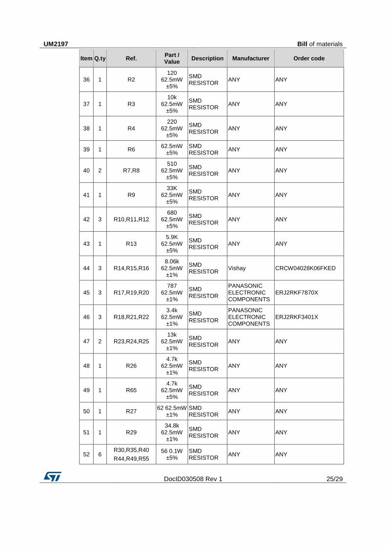
DocID030508 Rev 1 25/29
Item Q.ty Ref. Part / Value
Description Manufacturer Order code
36 1 R2 120
62.5mW ±5%
SMD RESISTOR
ANY ANY
37 1 R3 10k
62.5mW ±5%
SMD RESISTOR
ANY ANY
38 1 R4 220
62.5mW ±5%
SMD RESISTOR
ANY ANY
39 1 R6 62.5mW
±5% SMD RESISTOR
ANY ANY
40 2 R7,R8 510
62.5mW ±5%
SMD RESISTOR
ANY ANY
41 1 R9 33K
62.5mW ±5%
SMD RESISTOR
ANY ANY
42 3 R10,R11,R12 680
62.5mW ±5%
SMD RESISTOR
ANY ANY
43 1 R13 5.9K
62.5mW ±5%
SMD RESISTOR
ANY ANY
44 3 R14,R15,R16 8.06k
62.5mW ±1%
SMD RESISTOR
Vishay CRCW04028K06FKED
45 3 R17,R19,R20 787
62.5mW ±1%
SMD RESISTOR
PANASONIC ELECTRONIC COMPONENTS
ERJ2RKF7870X
46 3 R18,R21,R22 3.4k
62.5mW ±1%
SMD RESISTOR
PANASONIC ELECTRONIC COMPONENTS
ERJ2RKF3401X
47 2 R23,R24,R25 13k
62.5mW ±1%
SMD RESISTOR
ANY ANY
48 1 R26 4.7k
62.5mW ±1%
SMD RESISTOR
ANY ANY
49 1 R65 4.7k
62.5mW ±5%
SMD RESISTOR
ANY ANY
50 1 R27 62 62.5mW
±1% SMD RESISTOR
ANY ANY
51 1 R29 34.8k
62.5mW ±1%
SMD RESISTOR
ANY ANY
52 6 R30,R35,R40
R44,R49,R55
56 0.1W ±5%
SMD RESISTOR
ANY ANY

Bill of materials UM2197
26/29 DocID030508 Rev 1
Item Q.ty Ref. Part / Value
Description Manufacturer Order code
53 1 R31 300
62.5mW ±1%
SMD RESISTOR
ANY ANY
54 1 R32 8.2k
62.5mW ±1%
SMD RESISTOR
ANY ANY
55 6 R33,R37,R42
R45,R50,R59
100 0.1W ±5%
SMD RESISTOR
ANY ANY
56 6 R34,R38,R43
R47,R51,R61
10k 0.1W ±5%
SMD RESISTOR
ANY ANY
57 3 R36,R46,R58 1 0.125W
±5% SMD RESISTOR
ANY ANY
58 3 R52,R53,R54 33k 0.1W
±1% SMD RESISTOR
ANY ANY
59 3 R56,R57,R60 4.02k
62.5mW ±1%
SMD RESISTOR
ANY ANY
60 1 R62 169K
62.5mW ±1%
SMD RESISTOR
ANY ANY
61 1 R63 NTC 10K
±1% NTC Thermistor
TDK NTCG103JF103F
62 3 R64,R66,R67 0.01 3W
±1%
10 mohm SHUNT RESISTOR
Bourns CRA2512-FZ-R010ELF
KOA Speer TLR3APDTE10L0F50
63 1 R68 18K
62.5mW ±1%
SMD RESISTOR
ANY ANY
64 1
TP1,TP2,TP3,TP4
TP5,TP6,TP7,TP8
TP9,TP10,TP11
TP12,TP13,TP14
TP15
±0% TEST POINT: SMD PAD 1 mm
65 1 U1
CAN transceiver
TI SN65HVD230D
66 1 U2
32bit MCU ST STM32F303CBT7
67 3 U3,U4,U5
Rail-to-rail input/output 20 MHz GBP operational amplifiers
ST TSV991ILT
68 1 U6
3 A step-down switching regulator
ST L7986TR
69 3 U7,U10,U11
High voltage high and low-side driver
ST L6398D

UM2197 Bill of materials
DocID030508 Rev 1 27/29
Item Q.ty Ref. Part / Value
Description Manufacturer Order code
70 1 U8
Low Drop Voltage Regulator
ST LD39050PU33R
71 1 U9
Low Drop Voltage Regulator
ST LD1117S50TR
72 1 X1
Resonators 8Mhz
Murata Electronics
CSTCE8M00G55-R0

Revision history UM2197
28/29 DocID030508 Rev 1
6 Revision history Table 4: Document revision history
Date Version Changes
07-Apr-2017 1 Initial release.

UM2197
DocID030508 Rev 1 29/29
IMPORTANT NOTICE – PLEASE READ CAREFULLY
STMicroelectronics NV and its subsidiaries (“ST”) reserve the right to make changes, corrections, enhancements, modifications , and improvements to ST products and/or to this document at any time without notice. Purchasers should obtain the latest relevant information on ST products before placing orders. ST products are sold pursuant to ST’s terms and conditions of sale in place at the time of order acknowledgement.
Purchasers are solely responsible for the choice, selection, and use of ST products and ST assumes no liability for application assistance or the design of Purchasers’ products.
No license, express or implied, to any intellectual property right is granted by ST herein.
Resale of ST products with provisions different from the information set forth herein shall void any warranty granted by ST for such product.
ST and the ST logo are trademarks of ST. All other product or service names are the property of their respective owners.
Information in this document supersedes and replaces information previously supplied in any prior versions of this document.
© 2017 STMicroelectronics – All rights reserved