electronically managed suspension tmc introduction system overview sensors and control mechanisms...
TRANSCRIPT
ELECTRONICALLY MANAGED SUSPENSION
tmc
• introduction• system overview• sensors and control mechanisms• checking procedures
ELECTRONICALLY MANAGED SUSPENSION
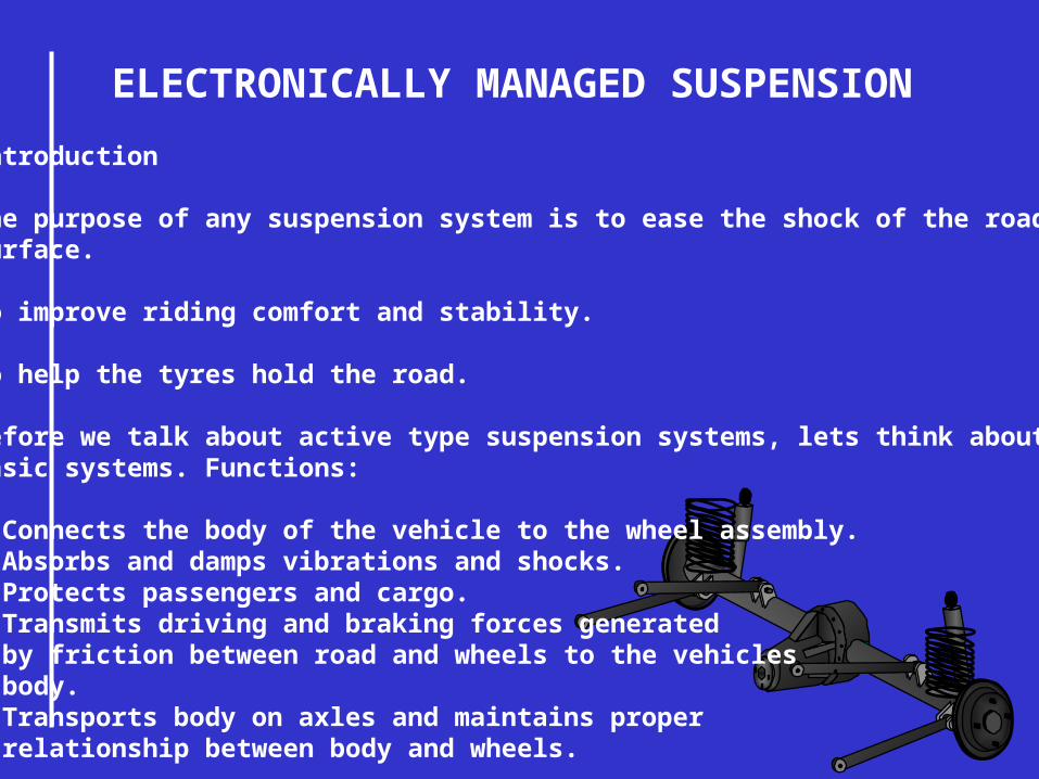
Introduction
The purpose of any suspension system is to ease the shock of the roadsurface.
To improve riding comfort and stability.
To help the tyres hold the road.
Before we talk about active type suspension systems, lets think about somebasic systems. Functions:
• Connects the body of the vehicle to the wheel assembly.• Absorbs and damps vibrations and shocks.• Protects passengers and cargo.• Transmits driving and braking forces generated by friction between road and wheels to the vehicles body.• Transports body on axles and maintains proper relationship between body and wheels.

ELECTRONICALLY MANAGED SUSPENSION
Shock Absorbers - Purpose
To improve ride handling and comfort by quicklydamping oscillations of the springs (up and downmovement).
Help tyres hold the road better.
TIME
AMPLITUDE
With shockabsorbers.
Without shockabsorbers.

ELECTRONICALLY MANAGED SUSPENSION
Action of the shockabsorber and springs.

ELECTRONICALLY MANAGED SUSPENSION
On electronic systems shock absorbers must reconcile 2 requirements.
1 = passenger comfort, for which dampening should be soft (85% of use).2 = performance dampening that should be hard.

ELECTRONICALLY MANAGED SUSPENSION

ELECTRONICALLY MANAGED SUSPENSION
Shock Absorber
Spring
Lower Wishbone
Upper Wishbone
ELECTRONICALLY MANAGED SUSPENSION
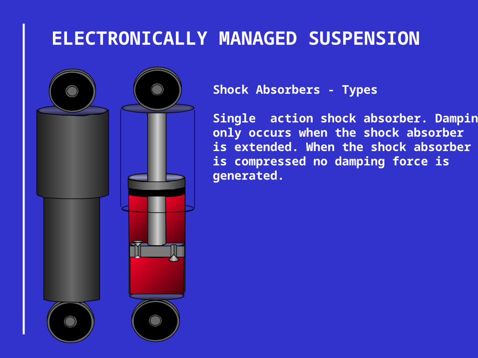
Shock Absorbers - Types
Single action shock absorber. Dampingonly occurs when the shock absorberis extended. When the shock absorberis compressed no damping force isgenerated.

ELECTRONICALLY MANAGED SUSPENSION
Orifice
Valve
Fluid

ELECTRONICALLY MANAGED SUSPENSION
Valve is now open, fluid flows from thelower chamber through the now openvalve and the orifice.
The flow resistance of the fluid movingthrough the orifice creates a dampingforce.

ELECTRONICALLY MANAGED SUSPENSION
Multi action shock absorbers.
Damping occurs when the shockabsorber is extended and whenit is compressed.

ELECTRONICALLY MANAGED SUSPENSIONTwin tube shockabsorbers.
Cylinder divided bypressure tube and outertube into working chamber(inner cylinder) andreservoir chamber (innerchamber).
When the piston is forceddown, oil which isincompressible flowsthrough a check valve anddamps the descent of thepiston. This process isreversed during rebound.As the plunger enters thecylinder an equivalentamount of oil enters the reservoir between the jacketand the cylinder.

ELECTRONICALLY MANAGED SUSPENSION
Gas filled shock absorbers:
Charged with mainly Nitrogen gas.
There are 2 main types:
Low pressure - 142 to 213 psi.
High pressure - 284 to 427 psi.
The smaller the check valves thestiffer the shock absorber.
The larger the valves the softerthe shock absorber.

ELECTRONICALLY MANAGED SUSPENSION
Normal

ELECTRONICALLY MANAGED SUSPENSION
Dive - braking

ELECTRONICALLY MANAGED SUSPENSION
Pitch - acceleration

ELECTRONICALLY MANAGED SUSPENSION
Pitching can also occur when the vehicle has gone over a hump orobstacle in the road and continues to oscillate.

ELECTRONICALLY MANAGED SUSPENSION
The roll caused by an evasivemanoeuvre or rapid lane changing.

ELECTRONICALLY MANAGED SUSPENSION
Normal Dive - braking
Pitch - acceleration
Roll
Pitching
ELECTRONICALLY MANAGED SUSPENSION
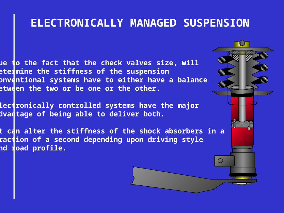
Due to the fact that the check valves size, willdetermine the stiffness of the suspension conventional systems have to either have a balancebetween the two or be one or the other.
Electronically controlled systems have the majoradvantage of being able to deliver both.
It can alter the stiffness of the shock absorbers in a fraction of a second depending upon driving styleand road profile.

ELECTRONICALLY MANAGED SUSPENSION
How does it work?
The twin tube shock absorber contains the following:
• Hollow plunger.
• Actuator.
• 16,000 rpm miniature electric motor.
• Reduction gear train, ratio 46 : 1.
• Torque limiter to cut power to the motor.
• Rotary valve.

ELECTRONICALLY MANAGED SUSPENSION
Channel closed damping is heavy.
SPORT position.
Actuator, rotates clockwise andanti clockwise.

ELECTRONICALLY MANAGED SUSPENSION
Channel open damping is soft.
COMFORT position.
Actuator, rotates clockwise andanti clockwise.

ELECTRONICALLY MANAGED SUSPENSION
ElectronicControlUnit
Steering angle sensor
Inputs for system requirements.
Outputs from the control unit.
Yaw / pitch sensor
Brake pressure switch
Pedal potentiometer
Vehicle speed sensor
Damper motor o/s/f
Drivers selector switch
Damper motor n/s/r
Damper motor o/s/r
Damper motor n/s/f

ELECTRONICALLY MANAGED SUSPENSION
The speed sensor is an inductive device.
PERMANENTMAGNET
SOFT IRON COREWINDING
It is a tiny alternator thatproduces an AC waveform.
ELECTRONICALLY MANAGED SUSPENSION
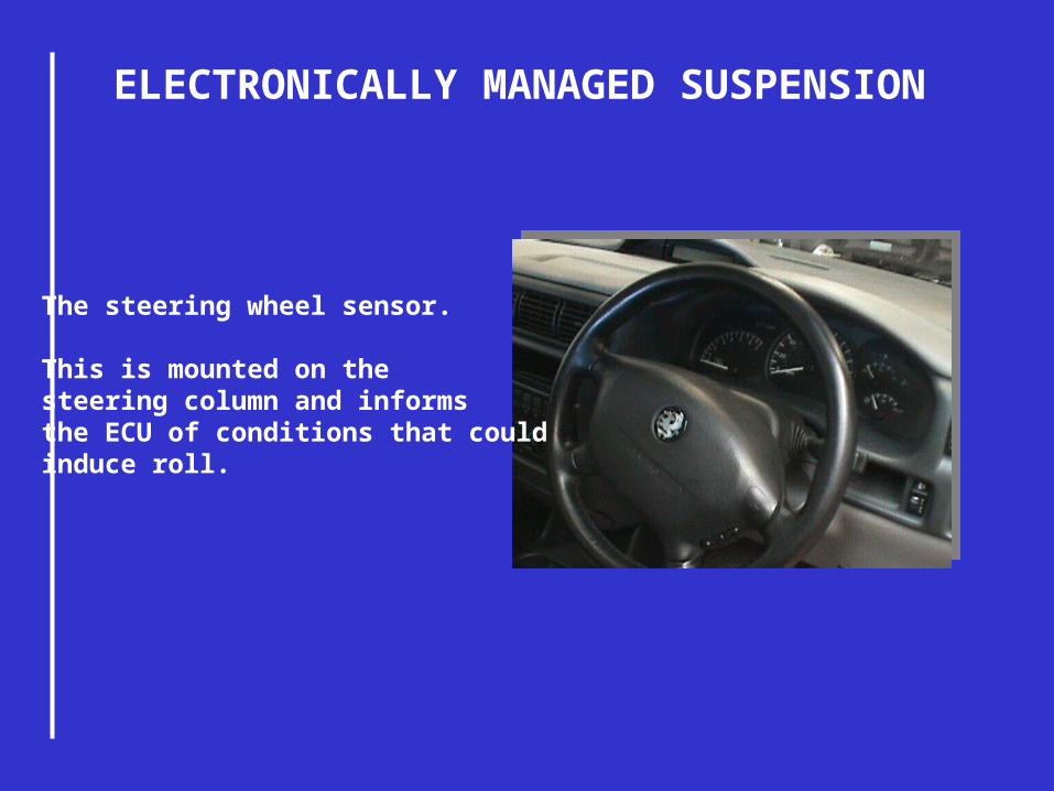
The steering wheel sensor.
This is mounted on the steering column and informsthe ECU of conditions that couldinduce roll.

ELECTRONICALLY MANAGED SUSPENSION
The steering wheel sensor. This measures the steering wheel angle and the speed in which it is rotated.
It consists of a Phonicwheel fitted to thesteering column.
The sensor itself consistsof 2 LED’s and 2 phototransistors.
The phonic wheelturns with the steering wheel andblocks or allowsthe light through tothe transistors.

ELECTRONICALLY MANAGED SUSPENSION
Yaw /pitch sensor - this measures suspension movement that mayinduce pitching or yawing movement.
Its mounted on the front sub - frame and connected by a link to the anti - swaybar.
During suspension travel the anti sway bar actuates the link. The link drivesa notched phonic wheel that blocks or allows through light from 4 LED’s.
The trim height iscalculated from thesuccession of signals.
SBY - LED’s

ELECTRONICALLY MANAGED SUSPENSION
The trim height iscalculated from thesuccession of signals.
SBY - LED’s
Yaw / Pitch sensor.

ELECTRONICALLY MANAGED SUSPENSION
Pedal potentiometer.
This evaluates the risk of front end lift ordive.
It delivers 2 types of information:
•The rate which the pedal is being operated.
•The amplitude of any acceleration or deceleration.

ELECTRONICALLY MANAGED SUSPENSION
The brake pressure sensor limits dive.
It consist of a switch that when the pressure exceeds 15 bars it opensthe circuit.
What does the ECU do with this information?
The ECU has basic maps programmedinto it’s memory with reference pointsfor all the sensors.

ELECTRONICALLY MANAGED SUSPENSION
What does the ECU do with this information?
Steering Angle Angular Velocity of the Steering Wheel
KM/H KM/H
O O/S

ELECTRONICALLY MANAGED SUSPENSION
KM/H KM/H
Body Height Amplitude of acceleration
H
5
4
3
O/S

ELECTRONICALLY MANAGED SUSPENSION
KM/H KM/H
Amplitude and rate of deceleration Braking pressure
O/S Bar
15

ELECTRONICALLY MANAGED SUSPENSION
Consider the reference point for the steering wheel angle. It defines2 zones a green zone and a blue zone.
Steering Angle
KM/H
O The vehicle enters a largeradius bend at 90km/h anda steering angle of 90°.
The point P is in the green zonenormal ride dampening.
15
5
90
P
15
5
90
P
The vehicle is travellingat the same speed but nowenters a sharp bend witha steering angle of 15°.It is now in the blue zone.
Sport position.

ELECTRONICALLY MANAGED SUSPENSION
The ECU sends asignal 150 m/s longto the shock absorberswhen point P is in theblue zone.
The valves of the4 shock absorbersclose changingto the sport position.

ELECTRONICALLY MANAGED SUSPENSION
These valves remainclosed for as long aspoint P stays in theblue zone.
When the ECUsenses a stablecondition for atleast 2 seconds itsends a signal 300 m/s long whichcloses the actuatorsin the shocks.
If a fault is detectedin the systems theECU forces all the valvesclosed - sport position.