electrostatic aspects: charging up effects of dielectrics
TRANSCRIPT

Electrostatic aspects: charging up effects of dielectricsBo Yu
Workshop on the LEM/Thick GEM cryogenic utilization in pure Argon over large detection surfaces
April 6-7, 2020

Outline
• Effect of charging up of insulator surfaces in ProtoDUNE SP - Drift field irregularities near field cage
• Space charge effect in dual phase LArTPC- Ion back flow fraction in DUNE DP LArTPC- Distortion in a DUNE DP geometry
• Other surface charging possibilities- Negative ion buildup on surface?
4/7/2020 Bo Yu | Charging up Effects2

Slide Title
• Click to edit Master text styles- Second level
• Third level- Fourth level
• Fifth level
4/7/2020 Bo Yu | Charging up Effects3
From: https://indico.fnal.gov/event/19354/contribution/1/material/slides/0.pdf

ProtoDUNE SP Field Cage
4/7/2020 Bo Yu | Charging up Effects4
The end wall field cage is constructed from a vertical stack of 4 modules, each has two horizontal fiberglass box beams (black) 152mm wide. There are also 70mm wide bands of UHMWPE caps (white) separating the vertical field cage electrodes.
3 such triplets of insulating surfaces run along the entire drift length.

FEA of the Field Lines Near the End Wall Field Cage
• This model is a quarter of a drift volume. The volume is filled with a positive charge distribution. The insulators are modeled as rectangular blocks with boundary condition of no E field normal to the surfaces, a result of a fully charged up condition.
• The field line plot clearly shows the triplet wavy pattern at the boundary of the drift volume.
• Even though these triplets appear as a “distortion” in drift field, they are actually close to the correct drift path without the space charge effect.
• On a LEM, the insulating surfaces inside the LEM holes will get charged up. How stable (in time) is the charge density on the surface determines the gain stability of the LEM.
• Will we see some hysteresis in the LEM gain after repeated calibration laser beam exposure?
4/7/2020 Bo Yu | Charging up Effects5

Estimated Electric Field Variation from Ar39 in a 12mx12m LArTPC Cross Section without Ion Back Flow
E = 500V/cmAr39: 1bq/kgMean energy loss: 220 keVRecombination survival: 2/3Max charge density near cathode: 2.1nC/m3
Maximum transverse distortion: ~ 5cm
Maximum E field distortion: 1%
This is essentially a single phase LArTPC with a single vertical drift
4/7/2020 Bo Yu | Charging up Effects6
Cathode
Anode
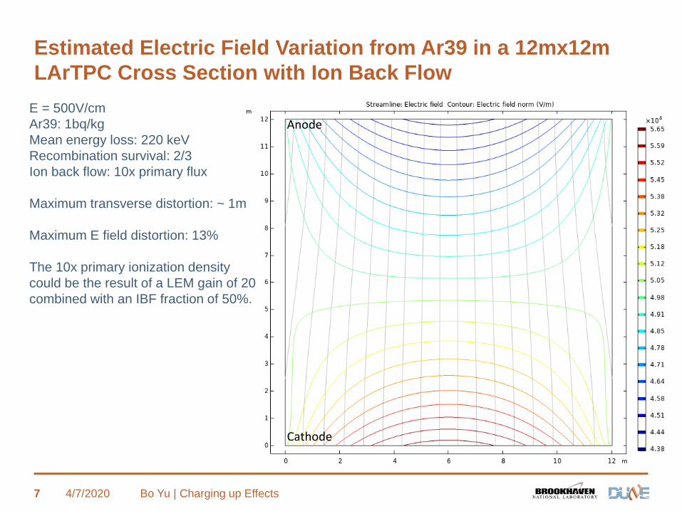
Estimated Electric Field Variation from Ar39 in a 12mx12m LArTPC Cross Section with Ion Back Flow
E = 500V/cmAr39: 1bq/kgMean energy loss: 220 keVRecombination survival: 2/3Ion back flow: 10x primary flux
Maximum transverse distortion: ~ 1m
Maximum E field distortion: 13%
The 10x primary ionization density could be the result of a LEM gain of 20 combined with an IBF fraction of 50%.
4/7/2020 Bo Yu | Charging up Effects7
Cathode
Anode

E Field Simulation of a DP LEM
4/7/2020 Bo Yu | Charging up Effects8
A 3D model of a small section of the drift, extraction, LEM, CRP region.
Extraction grid(10mm below LEM)
Liquid gas interface
LEM (0.5mm holes @ 0.8mm pitch, 1mm thick)
CRP 2kV/cm
30kV/cm
3kV/cm
2kV/cm
0.5kV/cm
A 2D cut plane near the front face of the model is plotted in the following slides.DP cross section view
From S. Murphy

Field Lines Around the DP LEM
4/7/2020 Bo Yu | Charging up Effects9
Electron drift lines coming from the drift region
About ½ of the LEM holes never see electrons coming from the drift region.
Primary ionization electron paths superimposed on the overall field lines
CRP
LEM
Liquid surface
Extraction grid
0.5kV/cm
2kV/cm
3kV/cm
2kV/cm

How Many Ions Are Collected by the LEM?
4/7/2020 Bo Yu | Charging up Effects10
Due to the unfavorable collection to extraction field ratio (2:3), a fraction (1/3?) of the electrons lands on the upper surface of the LEM, therefore not contributing to the CRP signal.
Electron multiplication occurs mostly in the blue region (with some broadening due to diffusion) inside the LEM holes. Only electrons in the narrower red channels reach the CRP and therefore contributing to the readout signal, and the apparent gain.
Diffusion of electrons and ions will alter their actual drift paths from these ideal lines (much less effective for ions).
Assuming the gain of the LEM is defined by the collected electrons reaching the CRP, the ions created by these electrons will follow the red lines down, and unlikely to be collected by the lower surface of the LEM: 100% IBF
Red lines are those reaching CRP
Blue lines are coming from the drift volume.

How Many Ions Does the Extraction Grid Block?
4/7/2020 Bo Yu | Charging up Effects11
Since the extraction to drift field ratio is 4:1, one could expect on average ¾ of the ions are blocked by the wire grid.
However, in this case, the electrons coming from the drift volume below, and contributing to the signal on CRP are in the purple region. The positive ions created by these signal electrons are also restricted in the purple region. As one can see, the field lines in the purpose region DO NOT reach the extraction wires: 100% transparency for the positive ions.
Diffusion of ions will alter their actual drift paths from these ideal lines. But this deviation is not expected to be significant during the 1cm travel from the LEM to the extraction grid.
It appears that the majority of the positive ions generated by electrons contributing to the CRP signals will flow back to the drift volume, therefore contributing to the space charge problem.
Red lines are those reaching CRP
Blue lines are coming from the drift volume.

Interaction of Ion and Liquid Flow
4/7/2020 Bo Yu | Charging up Effects12
I have not seen a CFD of the DP FD cryostat. The closest study I can find is this plot from Erik Voirin on a LBNE 33kt design, in which the cathodes are wire mesh with little impact on the liquid flow. The red bands represents regions where the liquid flow velocity is close to 8mm/s, the ion drift velocity @ 500V/cm field. The two blue circles indicate the region with possible stalled ion movement. On the other hand, the center of the cryostat should have reduced space charge build up due to the downward flow of the liquid.
If the flow pattern is stable, one could expect significant charge buildup in these regions
The center of the drift volume will see less charge buildup due to the increase in effective ion drift velocity

Positive Ion Space Charge Distortion vs Drift Length
4/7/2020 Bo Yu | Charging up Effects13
Based on a simple 2D model

What Happen to the Negative Ions?
4/7/2020 Bo Yu | Charging up Effects14
• Impurities in the LAr capture a fraction of the primary electrons. If the electron life time is poor, most of the electrons will be captured and form negative ions. These negative ions drift up toward the LEM.
• But can the negative ions be extracted into the gas phase by the 3kV/cm extraction field? Can the electron be striped off the ion and pulled into the gas by the extraction field?
• If the answers are NO for both questions, we have a problem:• The negative ions will build up at the liquid surface until their
self repulsive force push them to the field cage/cryostat wall. An equilibrium is reached, but the surface charge density will likely to be very non-uniform over the liquid surface.
• This non-uniform negative surface charge will distort the electron drift path, change the extraction field (reduce the field in the liquid, increase the field in the gas), alter the gas gain in the LEM.
• This effect has not been reported. Possibly because it is not obvious in a small detector.

Summary
• We have seen clear evidences of charge accumulation on insulating surfaces and the LAr bulk during the ProtoDUNE SP operation.
• The space charge effect is expected to be about 2 orders of magnitude less in the DUNE FD due to the underground siting. For the SP TPC, it is barely noticeable. However, in the DP TPC, the space charge distortion will be severe, due to the 12m drift length, and the high ion back flow.
• The possible stalling of ion drift by LAr convection flow could cause local E field variations, and make the E field distortion time dependent.
• We need better understanding of the behavior of the ions (+/-) on the liquid gas interface. Dedicated tests are needed.
4/7/2020 Bo Yu | Charging up Effects15