elg4139: power diodes and power transistorsrhabash/elg4139l311.pdf · the thyristor • thyristor,...
TRANSCRIPT

ELG4139: Power Diodes and Power Transistors
Selection Criteria
Voltage Rating
Current Rating
Switching Speeds
On-State Voltage
Switching Frequency
Transistor or Diode
Magnetic Components
Capacitor Selection
Thyristors; Power Diodes; Power Bipolar Transistors (BJTs) Power Metal Oxide Semiconductor Field Effect Transistors (MOSFETs);
Insulated Gate Bipolar Transistors (IGBTs); Gate Turn-Off Thyristors (GTOs)
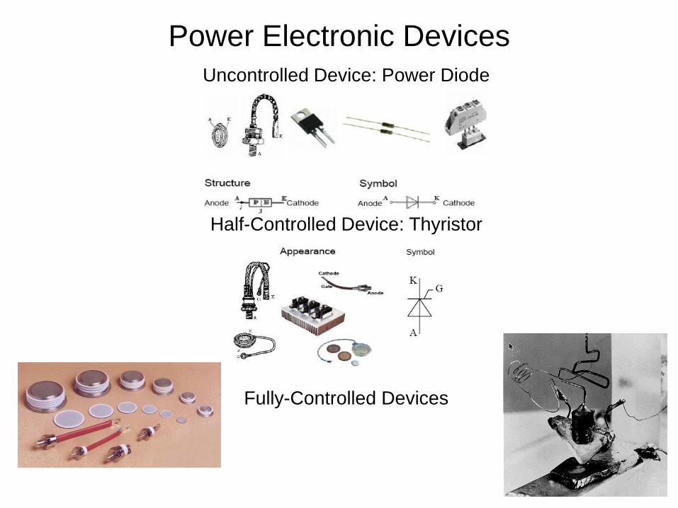
Power Electronic Devices
Uncontrolled Device: Power Diode
Half-Controlled Device: Thyristor
Fully-Controlled Devices
The Thyristor
• Thyristor, a three terminal, four layers solid state
semiconductor device, each layer consisting of alternately N-
type or P-type material, for example P-N-P-N, that can handle
high currents and high voltages, with better switching speed
and improved breakdown voltage .
• The name ‘thyristor’, is derived by a combination of the capital
letters from THYRatron and transISTOR.
• Thyristor has characteristics similar to a thyratron tube which
is a type of gas filled tube used as a high energy electrical
switch and controlled rectifier.
• From the construction view point, a thyristor (pnpn device)
belongs to transistor (pnp or npn device) family.
• This means that the thyristor is a solid state device like a
transistor and has characteristics similar to that of a thyratron
tube.
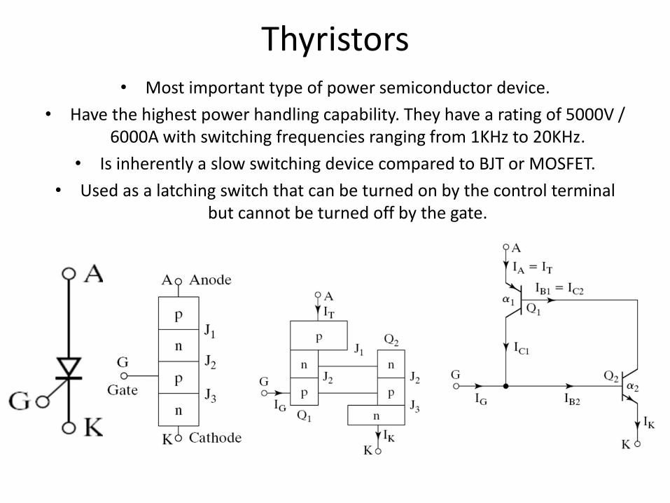
Thyristors • Most important type of power semiconductor device.
• Have the highest power handling capability. They have a rating of 5000V / 6000A with switching frequencies ranging from 1KHz to 20KHz.
• Is inherently a slow switching device compared to BJT or MOSFET.
• Used as a latching switch that can be turned on by the control terminal but cannot be turned off by the gate.

Methods of Thyristor Turn-on
• Thermal Turn-on.
• Light.
• High Voltage.
• Gate Current.
• dv/dt.

Thyristor Family Members
• SCR: Silicon Controlled Rectifier
• DIAC: Diode on Alternating Current
• TRIAC: Triode for Alternating Current
• SCS: Silicon Control Switch
• SUS: Silicon Unilateral Switch
• SBS: Silicon Bidirectional Switch
• SIS: Silicon Induction Switch
• LASCS: Light Activated Silicon Control Switch
• LASCR: Light Activated Silicon Control Rectifier
• SITh: Static Induction Thyristor
• RCT: Reverse Conducting Thyristor
• GTO: Gate Turn-Off Thyristor
• MCT: MOSFET Controlled Thyristor
• ETOs: Emitter Turn ON Thyristor

The Thyristor: Structure and Model
P 1
A
G
K
N 1
P 2 P 2
N 1
N 2
a)
NPN
PNP
A
G
K
I G
I K
I c2
I c1
I A
V 1
V 2
b)
Structure
Equivalent circuit
Equivalent
circuit
R
NPN
PNP
A
G
S
K
E G
I G
E A
I K
I c2
I c1
I A
V 1
V 2
Equivalent circuit: A pnp transistor and an npn
transistor interconnected together
Positive feedback
Trigger
Can not be turned off by control
signal
Half-controllable
I c1=α1 IA + I CBO1 (1-1)
I c2= α2 IK + I CBO2 (1-2)
IK=IA+IG (1-3)
IA=Ic1+Ic2 (1-4)
(
I I I
) 1 2 1
CBO2 CBO1 G 2 A
I ( 1-5 )
SCR
2N3668
ANODE
CATHODE
GATE

Silicon Controlled Rectifier Industrially SCRs are applied to produce DC voltages for motors from
AC line voltage. As rectifier, they can be half-wave rectifiers and full-
wave rectifier.

Typical Fully-Controlled Devices Gate- Turn-Off Thyristor: GTO
Major difference from conventional thyristor: The gate
and cathode structures are highly inter-digitated , with
various types of geometric forms being used to layout
the gates and cathodes.
R
NPN
PNP
A
G
S
K
E G
I G
E A
I K
I c2
I c1
I A
V 1
V 2

Triac
Resembles a bidirectional thyristor; allows full-wave control using a single device often used with a
bidirectional trigger diode (a diac) to produce the necessary drive pulses this breaks down at a particular
voltage and fires the triac.

Application: DC Motor Driver
• DC motor speed generally depends on a combination of
the voltage and current flowing in the motor coils and the
motor loads or braking torque.
• The speed of the motor is proportional to the voltage,
and the torque is proportional to the current.
• A rectifier is one or more diodes arranged for converting AC to DC.
• The current used to drive the DC motor typically comes from:
Fixed voltage: Battery; Voltage regulator.
Adjustable voltage: PWM current source; Silicon controlled rectifier modulated AC source.

DC Motors Current Drives

DC Motors Current Drives

Power Transistors
• MOSFET: Metal Oxide Semiconductor Field Effect Transistor
• (Below few hundreds voltages; Switching frequencies in excess of 100 kHz)
• IGBT: Insulated Gate Bipolar Transistor (Very large voltage; current and power extending MW; switching below few tens of kHz)
• IGCT: Integrated Gate Controlled Thyristor (Utility applications of few MWs).
• GTO: Gate-Turn Off Thyristor (Utility applications of few MWs).
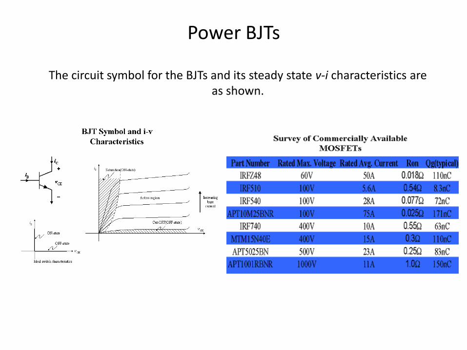
Power BJTs
The circuit symbol for the BJTs and its steady state v-i characteristics are as shown.

Power BJTs
16
As shown in the i-v characteristics, a sufficiently large base current results in the device being fully ON. This requires that the control circuit to
provide a base current that is sufficiently large so that
where hFE is the dc current gain of the device
FEh
CIBI
BJTs are current-controlled devices, and base current must be supplied continuously to keep them in the ON state: The dc current
gain hFE is usually only 5-10 in high-power transistors. BJTs are available in voltage ratings up to 1400V and current ratings
of a few hundred amperes.
BJT has been replaced by MOSFET in low-voltage (< 500V) applications
BJT is being replaced by IGBT in applications at voltages above 500V
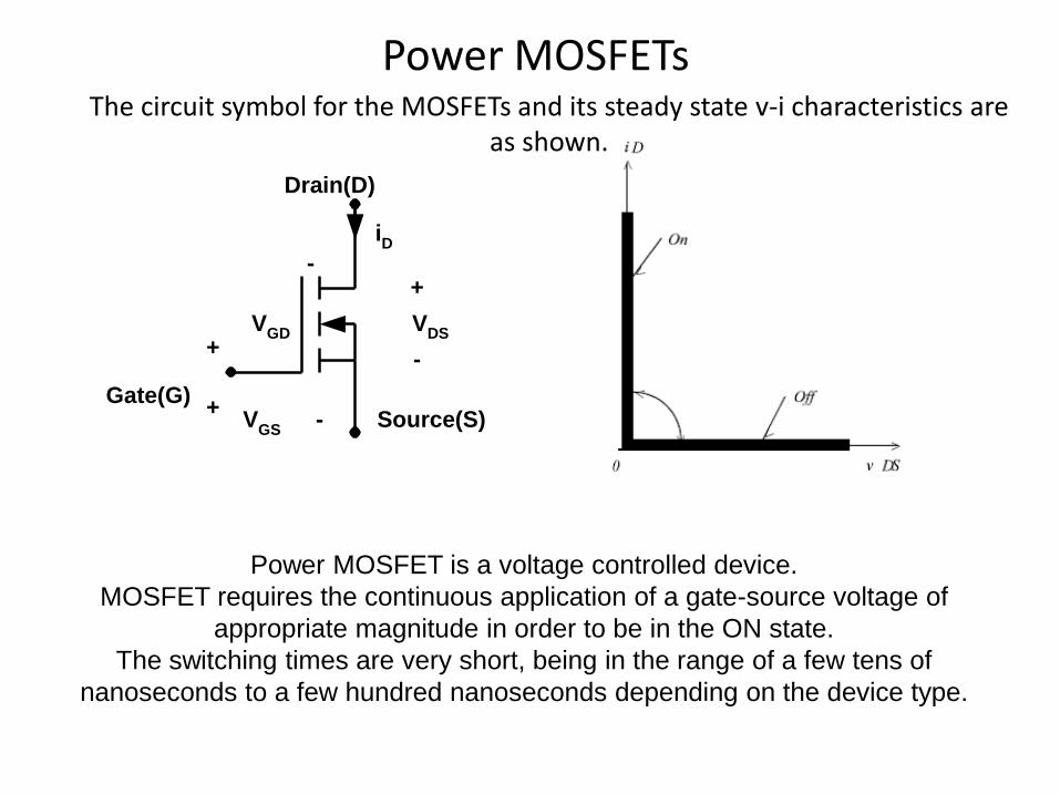
Power MOSFETs
+-
iD
Gate(G)Source(S)
VDS
VGD
+-
+-
Drain(D)
VGS
The circuit symbol for the MOSFETs and its steady state v-i characteristics are as shown.
Power MOSFET is a voltage controlled device.
MOSFET requires the continuous application of a gate-source voltage of
appropriate magnitude in order to be in the ON state.
The switching times are very short, being in the range of a few tens of
nanoseconds to a few hundred nanoseconds depending on the device type.

MOSFETS
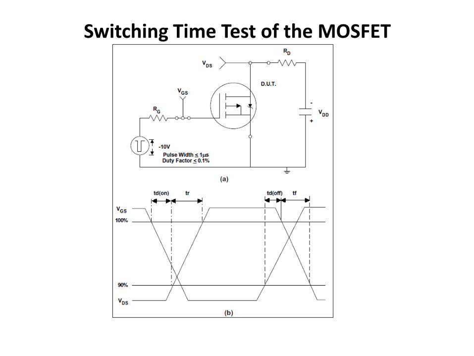
Switching Time Test of the MOSFET

IGBTs The circuit symbol for the IGBTs and its steady state v-i characteristics are as
shown. The IGBT has some of the
advantages of the MOSFET
and the BJT combined.
Similar to the MOSFET, the
IGBT has a high impedance
Gate, which requires only a
small amount of energy to
switch the device.
Like the BJT, the IGBT has a
small ON-state voltage even
in devices with large blocking
voltage ratings (for example,
VON is 2-3V in a 1000-V
device).
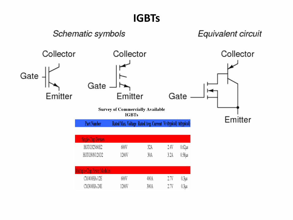
IGBTs
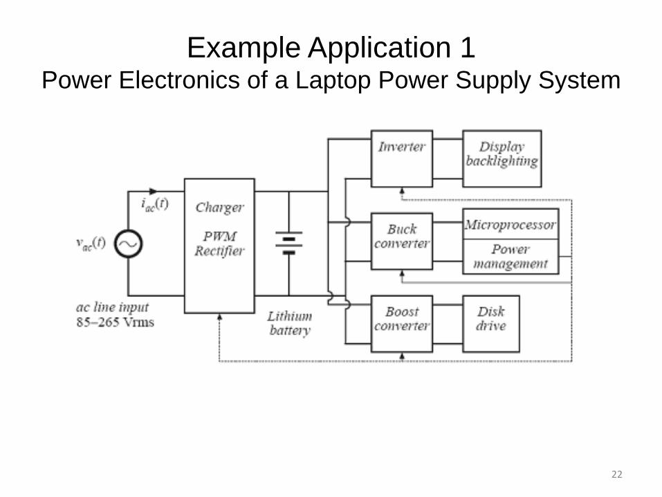
Example Application 1 Power Electronics of a Laptop Power Supply System
22
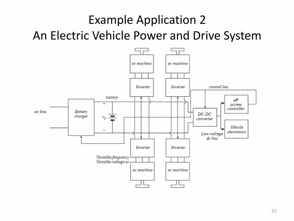
Example Application 2 An Electric Vehicle Power and Drive System
23

Transient Protection of Power Devices
dt
dv
Snubber circuit limits
as well as voltage and peak current in a switching device to safe specified limits!
dt
dv
,
dt
di
Switching device’s
Rating is significant during the switching device (thyristor) turn-OFF process. Voltage can increase very rapidly to high levels. If the rate rise is excessive, it may cause damage to the device.
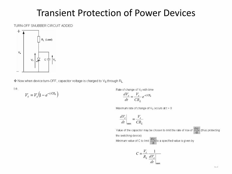
Transient Protection of Power Devices
25

Assignment in the Lab • Use Multisim to investigate the speed of an n-channel enhanced mode
MOSFET (IRF530N) in response to an input of 500 kHz, 50% duty cycle, 12 Vpeak, load = 6 ohm, Vcc = 12 V.