em-900 series electric guns - nordsonemanuals.nordson.com/adhesives/english_manuals/1034108.pdf ·...
TRANSCRIPT

NORDSON CORPORATION DULUTH, GEORGIA USAwww.nordson.com
This document contains important safety informationBe sure to read and follow all safety information in thisdocument and any other related documentation.
EM-900 Series Electric Guns
Customer Product ManualPart 1034108_04
Issued 8/11

Part 1034108_04 � 2011 Nordson CorporationAll rights reserved
For CE Declaration, refer to equipment documentation.
Nordson Corporation welcomes requests for information, comments, and inquiries about its products. General informationabout Nordson can be found on the Internet using the following address: http://www.nordson.com.
Address all correspondence to:
Nordson CorporationAttn: Customer Service11475 Lakefield Drive
Duluth, GA 30097
Notice
This is a Nordson Corporation publication which is protected by copyright. Original copyright date 2003.No�part�of�this�document may be photocopied, reproduced, or translated to another language without the prior written
consent of Nordson�Corporation. The�information�contained in this publication is subject to change without notice.
Trademarks
AccuJet, AeroCharge, Apogee, AquaGuard, Asymtek, Automove, Baitgun, Blue Box, Bowtie, CanWorks, Century, CF, CleanSleeve, CleanSpray, ColorMax,Color‐on‐Demand, Control�Coat, Coolwave, Cross‐Cut, cScan+, Dispensejet, DispenseMate, DuraBlue, DuraDrum, Durafiber, DuraPail, Dura‐Screen,Durasystem, Easy�Coat, Easymove Plus, Ecodry, Econo‐Coat, e.DOT, EFD, Emerald, Encore, ESP, e stylized, ETI ‐ stylized, Excel 2000, Fillmaster,
FlexiCoat, Flex‐O‐Coat, Flow Sentry, Fluidmove, FoamMelt, FoamMix, Fulfill, GreenUV, HDLV, Heli‐flow, Horizon, Hot Shot, iControl, iDry, iFlow, Isocoil,Isocore, Iso‐Flo, iTRAX, Kinetix, LEAN�CELL, Little�Squirt, LogiComm, Magnastatic, March, Maverick, MEG, Meltex, Microcoat, Micromark, MicroSet,
Millennium, Mini Squirt, Mountaingate, Nordson, Optimum, Package of Values, Pattern View, PermaFlo, PicoDot, Porous�Coat, PowderGrid, Powderware,Precisecoat, PRIMARC, Printplus, Prism, ProBlue, Prodigy, Pro‐Flo, ProLink, Pro‐Meter, Pro‐Stream, RBX, Rhino, Saturn, Saturn with rings, Scoreguard,Seal Sentry, Select�Charge, Select�Coat, Select Cure, Signature, Slautterback, Smart‐Coat, Solder Plus, Spectrum, Speed‐Coat, SureBead, Sure Coat,
Sure‐Max, Sure Wrap, Tracking�Plus, TRAK, Trends, Tribomatic, TrueBlue, TrueCoat, Ultra, UpTime, u‐TAH, Vantage, VersaBlue, Versa‐Coat, VersaDrum,VersaPail, Versa‐Screen, Versa‐Spray, Watermark, and When you expect more. are registered trademarks of Nordson Corporation.
Accubar, Advanced Plasma Systems, AeroDeck, AeroWash, AltaBlue, AltaSlot, Alta Spray, Artiste, ATS, Auto‐Flo, AutoScan, Axiom, Best Choice, Blue Series, Bravura, CanPro, Champion, Check Mate, ClassicBlue, Classic IX, Clean�Coat, Cobalt, Controlled Fiberization, Control�Weave, ContourCoat,
CPX, cSelect, Cyclo‐Kinetic, DispensLink, Dry Cure, DuraBraid, DuraCoat, DuraPUR, Easy Clean, EasyOn, EasyPW, Eclipse, e.dot+, E‐Nordson, Equalizer,EquiBead, FillEasy, Fill�Sentry, Flow Coat, Fluxplus, Get Green With Blue, G‐Net, G‐Site, IntelliJet, iON, Iso‐Flex, iTrend, Lacquer Cure, Maxima, Mesa,
MicroFin, MicroMax, Mikros, MiniBlue, MiniEdge, Minimeter, Multifill, MultiScan, Myritex, Nano, NexJet, OmniScan, OptiMix, OptiStroke, Partnership+Plus,PatternJet, PatternPro, PCI, Pinnacle, Plasmod, Powder�Pilot, Powder Port, Powercure, Process Sentry, Pulse Spray, PURBlue, PURJet, Ready Coat,
RediCoat, Royal Blue, Select�Series, Sensomatic, Shaftshield, SheetAire, Smart, Smartfil, SolidBlue, Spectral, SpeedKing, Spray Works, Summit, SureFoam,Sure�Mix, SureSeal, Swirl�Coat, TAH, ThruWave, Trade�Plus, Trilogy, Ultra FoamMix, UltraMax, Ultrasaver, Ultrasmart, Universal, ValueMate, Versa, Vista,
Web Cure, and 2�Rings (Design) are�trademarks of Nordson�Corporation.
Designations and trademarks stated in this document may be brands that, when used by third parties for their own purposes, could lead to violation of the owners' rights.

Table of Contents i
Part 1034108_04� 2011 Nordson Corporation
Safety 1. . . . . . . . . . . . . . . . . . . . . . . . . . . . . . . . . . . . . . . . . . . . . . . . . . . . . .Safety Alert Symbols 1. . . . . . . . . . . . . . . . . . . . . . . . . . . . . . . . . . . . . . . . . .Responsibilities of the Equipment Owner 2. . . . . . . . . . . . . . . . . . . . . . . . .
Safety Information 2. . . . . . . . . . . . . . . . . . . . . . . . . . . . . . . . . . . . . . . . . .Instructions, Requirements, and Standards 2. . . . . . . . . . . . . . . . . . . .User Qualifications 2. . . . . . . . . . . . . . . . . . . . . . . . . . . . . . . . . . . . . . . . .
Applicable Industry Safety Practices 3. . . . . . . . . . . . . . . . . . . . . . . . . . . .Intended Use of the Equipment 3. . . . . . . . . . . . . . . . . . . . . . . . . . . . . . .Instructions and Safety Messages 3. . . . . . . . . . . . . . . . . . . . . . . . . . . .Installation Practices 3. . . . . . . . . . . . . . . . . . . . . . . . . . . . . . . . . . . . . . . .Operating Practices 4. . . . . . . . . . . . . . . . . . . . . . . . . . . . . . . . . . . . . . . .Maintenance and Repair Practices 4. . . . . . . . . . . . . . . . . . . . . . . . . . .
Equipment Safety Information 4. . . . . . . . . . . . . . . . . . . . . . . . . . . . . . . . . .Equipment Shutdown 4. . . . . . . . . . . . . . . . . . . . . . . . . . . . . . . . . . . . . . .
Relieving System Hydraulic Pressure 5. . . . . . . . . . . . . . . . . . . . . . .De‐energizing the System 5. . . . . . . . . . . . . . . . . . . . . . . . . . . . . . . . .Disabling the Guns 5. . . . . . . . . . . . . . . . . . . . . . . . . . . . . . . . . . . . . . .
General Safety Warnings and Cautions 5. . . . . . . . . . . . . . . . . . . . . . . .Other Safety Precautions 7. . . . . . . . . . . . . . . . . . . . . . . . . . . . . . . . . . . .First Aid 8. . . . . . . . . . . . . . . . . . . . . . . . . . . . . . . . . . . . . . . . . . . . . . . . . . .
Safety Labels and Tags 8. . . . . . . . . . . . . . . . . . . . . . . . . . . . . . . . . . . . . . .
Description 10. . . . . . . . . . . . . . . . . . . . . . . . . . . . . . . . . . . . . . . . . . . . . . . . . .
Installation 11. . . . . . . . . . . . . . . . . . . . . . . . . . . . . . . . . . . . . . . . . . . . . . . . . . .Mounting the Gun 11. . . . . . . . . . . . . . . . . . . . . . . . . . . . . . . . . . . . . . . . . . . .Connecting the Hose 12. . . . . . . . . . . . . . . . . . . . . . . . . . . . . . . . . . . . . . . . . .Making the Electrical Connections 13. . . . . . . . . . . . . . . . . . . . . . . . . . . . . .Preparing for Operation 14. . . . . . . . . . . . . . . . . . . . . . . . . . . . . . . . . . . . . . .Setting the Gun Temperature 14. . . . . . . . . . . . . . . . . . . . . . . . . . . . . . . . . . .Adjusting the Module Stroke 14. . . . . . . . . . . . . . . . . . . . . . . . . . . . . . . . . . .
To adjust the module stroke: 14. . . . . . . . . . . . . . . . . . . . . . . . . . . . . . .
Maintenance 15. . . . . . . . . . . . . . . . . . . . . . . . . . . . . . . . . . . . . . . . . . . . . . . .Recommended Maintenance Schedule 15. . . . . . . . . . . . . . . . . . . . . . . . . .Cleaning Nozzles 15. . . . . . . . . . . . . . . . . . . . . . . . . . . . . . . . . . . . . . . . . . . . .Servicing a Saturn Filter 16. . . . . . . . . . . . . . . . . . . . . . . . . . . . . . . . . . . . . . .
Troubleshooting 17. . . . . . . . . . . . . . . . . . . . . . . . . . . . . . . . . . . . . . . . . . . . . .
Repair 24. . . . . . . . . . . . . . . . . . . . . . . . . . . . . . . . . . . . . . . . . . . . . . . . . . . . . .Replacing a Module 24. . . . . . . . . . . . . . . . . . . . . . . . . . . . . . . . . . . . . . . . . . .
Remove a Module 24. . . . . . . . . . . . . . . . . . . . . . . . . . . . . . . . . . . . . . . . . .Install a Module 25. . . . . . . . . . . . . . . . . . . . . . . . . . . . . . . . . . . . . . . . . . . .
Replacing a Coil and Housing Assembly 26. . . . . . . . . . . . . . . . . . . . . . . . .Replacing a Module Component 27. . . . . . . . . . . . . . . . . . . . . . . . . . . . . . . .
Disassemble the Module 27. . . . . . . . . . . . . . . . . . . . . . . . . . . . . . . . . . . .Reassemble the Module 28. . . . . . . . . . . . . . . . . . . . . . . . . . . . . . . . . . . .
Replacing the Coil Connector 29. . . . . . . . . . . . . . . . . . . . . . . . . . . . . . . . . .Blocking a Module Port 30. . . . . . . . . . . . . . . . . . . . . . . . . . . . . . . . . . . . . . . .Replacing a Heater 31. . . . . . . . . . . . . . . . . . . . . . . . . . . . . . . . . . . . . . . . . . .Replacing an RTD 32. . . . . . . . . . . . . . . . . . . . . . . . . . . . . . . . . . . . . . . . . . . .Replacing a Nozzle 33. . . . . . . . . . . . . . . . . . . . . . . . . . . . . . . . . . . . . . . . . . .

Table of Contentsii
Part 1034108_04 � 2011 Nordson Corporation
Parts 34. . . . . . . . . . . . . . . . . . . . . . . . . . . . . . . . . . . . . . . . . . . . . . . . . . . . . . .Gun Assemblies 35. . . . . . . . . . . . . . . . . . . . . . . . . . . . . . . . . . . . . . . . . . . . . .
EM‐901 35. . . . . . . . . . . . . . . . . . . . . . . . . . . . . . . . . . . . . . . . . . . . . . . . . . .EM‐902 35. . . . . . . . . . . . . . . . . . . . . . . . . . . . . . . . . . . . . . . . . . . . . . . . . . .EM‐903 35. . . . . . . . . . . . . . . . . . . . . . . . . . . . . . . . . . . . . . . . . . . . . . . . . . .EM‐904 35. . . . . . . . . . . . . . . . . . . . . . . . . . . . . . . . . . . . . . . . . . . . . . . . . . .
Gun Parts 36. . . . . . . . . . . . . . . . . . . . . . . . . . . . . . . . . . . . . . . . . . . . . . . . . . .Replacement Modules for EM‐900 Guns 38. . . . . . . . . . . . . . . . . . . . . . . . .Module Rebuild Kits 39. . . . . . . . . . . . . . . . . . . . . . . . . . . . . . . . . . . . . . . . . .Heater and RTD Kits 41. . . . . . . . . . . . . . . . . . . . . . . . . . . . . . . . . . . . . . . . . .Filter Kits 41. . . . . . . . . . . . . . . . . . . . . . . . . . . . . . . . . . . . . . . . . . . . . . . . . . . .Driver Cable Assemblies 42. . . . . . . . . . . . . . . . . . . . . . . . . . . . . . . . . . . . . .EM Series Gun Drivers 42. . . . . . . . . . . . . . . . . . . . . . . . . . . . . . . . . . . . . . . .Extrusion Nozzles 43. . . . . . . . . . . . . . . . . . . . . . . . . . . . . . . . . . . . . . . . . . . .
Straight Nozzles 43. . . . . . . . . . . . . . . . . . . . . . . . . . . . . . . . . . . . . . . . . . .Right‐Angle Nozzles, One Orifice 43. . . . . . . . . . . . . . . . . . . . . . . . . . . . .Right‐Angle Nozzles, Two Orifices 44. . . . . . . . . . . . . . . . . . . . . . . . . . . .Button Nozzles 44. . . . . . . . . . . . . . . . . . . . . . . . . . . . . . . . . . . . . . . . . . . .Insert Nozzles 45. . . . . . . . . . . . . . . . . . . . . . . . . . . . . . . . . . . . . . . . . . . . .
Swirl Nozzles 46. . . . . . . . . . . . . . . . . . . . . . . . . . . . . . . . . . . . . . . . . . . . . . . .Swirl Nozzles 46. . . . . . . . . . . . . . . . . . . . . . . . . . . . . . . . . . . . . . . . . . . . . .Controlled Fiberization (CF) Nozzle 46. . . . . . . . . . . . . . . . . . . . . . . . . . .
Swirl Adapter Kit 47. . . . . . . . . . . . . . . . . . . . . . . . . . . . . . . . . . . . . . . . . . . . .Hose Adapter Fittings 47. . . . . . . . . . . . . . . . . . . . . . . . . . . . . . . . . . . . . . . . .
Technical Data 48. . . . . . . . . . . . . . . . . . . . . . . . . . . . . . . . . . . . . . . . . . . . . .Specifications 48. . . . . . . . . . . . . . . . . . . . . . . . . . . . . . . . . . . . . . . . . . . . . . . .Module Performance 48. . . . . . . . . . . . . . . . . . . . . . . . . . . . . . . . . . . . . . . . . .Resistance Values 49. . . . . . . . . . . . . . . . . . . . . . . . . . . . . . . . . . . . . . . . . . . .
Gun RTD Resistance 49. . . . . . . . . . . . . . . . . . . . . . . . . . . . . . . . . . . . . . .Gun Heater Resistance 49. . . . . . . . . . . . . . . . . . . . . . . . . . . . . . . . . . . . .Module Coil Resistance 50. . . . . . . . . . . . . . . . . . . . . . . . . . . . . . . . . . . . .Hose Heater Resistance (in Ohms) 50. . . . . . . . . . . . . . . . . . . . . . . . . . .
Wiring Diagrams 51. . . . . . . . . . . . . . . . . . . . . . . . . . . . . . . . . . . . . . . . . . . . .Dimensions 53. . . . . . . . . . . . . . . . . . . . . . . . . . . . . . . . . . . . . . . . . . . . . . . . . .

EM-900 Series Electric Guns 1
Part 1034108_04� 2011 Nordson Corporation
EM-900 Series Electric Guns
Safety Read this section before using the equipment. This section containsrecommendations and practices applicable to the safe installation, operation,and maintenance (hereafter referred to as “use”) of the product described inthis document (hereafter referred to as “equipment”). Additional safetyinformation, in the form of task‐specific safety alert messages, appears asappropriate throughout this document.
WARNING! Failure to follow the safety messages, recommendations, andhazard avoidance procedures provided in this document can result inpersonal injury, including death, or damage to equipment or property.
Safety Alert Symbols
The following safety alert symbol and signal words are used throughout thisdocument to alert the reader to personal safety hazards or to identifyconditions that may result in damage to equipment or property. Comply withall safety information that follows the signal word.
WARNING! Indicates a potentially hazardous situation that, if not avoided,can result in serious personal injury, including death.
CAUTION: Indicates a potentially hazardous situation that, if not avoided,can result in minor or moderate personal injury.
CAUTION: (Used without the safety alert symbol) Indicates a potentiallyhazardous situation that, if not avoided, can result in damage to equipmentor property.

EM-900 Series Electric Guns2
Part 1034108_04 � 2011 Nordson Corporation
Responsibilities of the Equipment Owner
Equipment owners are responsible for managing safety information, ensuringthat all instructions and regulatory requirements for use of the equipment aremet, and for qualifying all potential users.
Safety Information � Research and evaluate safety information from all applicable sources,
including the owner‐specific safety policy, best industry practices,governing regulations, material manufacturer's product information, andthis document.
� Make safety information available to equipment users in accordance with
governing regulations. Contact the authority having jurisdiction forinformation.
� Maintain safety information, including the safety labels affixed to the
equipment, in readable condition.
Instructions, Requirements, and Standards � Ensure that the equipment is used in accordance with the information
provided in this document, governing codes and regulations, and bestindustry practices.
� If applicable, receive approval from your facility's engineering or safety
department, or other similar function within your organization, beforeinstalling or operating the equipment for the first time.
� Provide appropriate emergency and first aid equipment.
� Conduct safety inspections to ensure required practices are being
followed.
� Re‐evaluate safety practices and procedures whenever changes are
made to the process or equipment.
User Qualifications
Equipment owners are responsible for ensuring that users:
� receive safety training appropriate to their job function as directed by
governing regulations and best industry practices
� are familiar with the equipment owner's safety and accident
prevention policies and procedures
� receive, equipment‐ and task‐specific training from another qualified
individual
NOTE: Nordson can provide equipment‐specific installation,operation, and maintenance training. Contact your Nordsonrepresentative for information
� possess industry‐ and trade‐specific skills and a level of experience
appropriate to their job function

EM-900 Series Electric Guns 3
Part 1034108_04� 2011 Nordson Corporation
� are physically capable of performing their job function and are not
under the influence of any substance that degrades their mentalcapacity or physical capabilities
Applicable Industry Safety Practices
The following safety practices apply to the use of the equipment in themanner described in this document. The information provided here is notmeant to include all possible safety practices, but represents the best safetypractices for equipment of similar hazard potential used in similar industries.
Intended Use of the Equipment � Use the equipment only for the purposes described and within the limits
specified in this document.
� Do not modify the equipment.
� Do not use incompatible materials or unapproved auxiliary devices.
Contact your Nordson representative if you have any questions onmaterial compatibility or the use of non‐standard auxiliary devices.
Instructions and Safety Messages � Read and follow the instructions provided in this document and other
referenced documents.
� Familiarize yourself with the location and meaning of the safety warning
labels and tags affixed to the equipment. Refer to Safety Labels and Tagsat the end of this section.
� If you are unsure of how to use the equipment, contact your Nordson
representative for assistance.
Installation Practices � Install the equipment in accordance with the instructions provided in this
document and in the documentation provided with auxiliary devices.
� Ensure that the equipment is rated for the environment in which it will be
used and that the processing characteristics of the material will not createa hazardous environment. Refer to the Material Safety Data Sheet(MSDS) for the material.
� If the required installation configuration does not match the installation
instructions, contact your Nordson representative for assistance.
� Position the equipment for safe operation. Observe the requirements for
clearance between the equipment and other objects.
� Install lockable power disconnects to isolate the equipment and all
independently powered auxiliary devices from their power sources.
� Properly ground all equipment. Contact your local building code
enforcement agency for specific requirements.
� Ensure that fuses of the correct type and rating are installed in fused
equipment.
� Contact the authority having jurisdiction to determine the requirement for
installation permits or inspections.

EM-900 Series Electric Guns4
Part 1034108_04 � 2011 Nordson Corporation
Operating Practices � Familiarize yourself with the location and operation of all safety devices
and indicators.
� Confirm that the equipment, including all safety devices (guards,
interlocks, etc.), is in good working order and that the requiredenvironmental conditions exist.
� Use the personal protective equipment (PPE) specified for each task.
Refer to Equipment Safety Information or the material manufacturer'sinstructions and MSDS for PPE requirements.
� Do not use equipment that is malfunctioning or shows signs of a potential
malfunction.
Maintenance and Repair Practices � Perform scheduled maintenance activities at the intervals described in
this document.
� Relieve system hydraulic and pneumatic pressure before servicing the
equipment.
� De‐energize the equipment and all auxiliary devices before servicing the
equipment.
� Use only new factory‐authorized refurbished or replacement parts.
� Read and comply with the manufacturer's instructions and the MSDS
supplied with equipment cleaning compounds.
NOTE: MSDSs for cleaning compounds that are sold by Nordson areavailable at www.nordson.com or by calling your Nordson representative.
� Confirm the correct operation of all safety devices before placing the
equipment back into operation.
� Dispose of waste cleaning compounds and residual process materials
according to governing regulations. Refer to the applicable MSDS orcontact the authority having jurisdiction for information.
� Keep equipment safety warning labels clean. Replace worn or damaged
labels.
Equipment Safety Information
This equipment safety information is applicable to the following types ofNordson equipment:
� hot melt and cold adhesive application equipment and all related
accessories
� pattern controllers, timers, detection and verification systems, and all
other optional process control devices
Equipment Shutdown
To safely complete many of the procedures described in this document, theequipment must first be shut down. The level of shut down required varies bythe type of equipment in use and the procedure being completed.

EM-900 Series Electric Guns 5
Part 1034108_04� 2011 Nordson Corporation
If required, shut down instructions are specified at the start of the procedure.The levels of shut down are:
Relieving System Hydraulic Pressure
Completely relieve system hydraulic pressure before breaking any hydraulicconnection or seal. Refer to the melter‐specific product manual forinstructions on relieving system hydraulic pressure.
De‐energizing the System
Isolate the system (melter, hoses, guns, and optional devices) from all powersources before accessing any unprotected high‐voltage wiring or connectionpoint.
1. Turn off the equipment and all auxiliary devices connected to theequipment (system).
2. To prevent the equipment from being accidentally energized, lock andtag the disconnect switch(es) or circuit breaker(s) that provide inputelectrical power to the equipment and optional devices.
NOTE: Government regulations and industry standards dictate specificrequirements for the isolation of hazardous energy sources. Refer to theappropriate regulation or standard.
Disabling the Guns
All electrical or mechanical devices that provide an activation signal to theguns, gun solenoid valve(s), or the melter pump must be disabled beforework can be performed on or around a gun that is connected to a pressurizedsystem.
1. Turn off or disconnect the gun triggering device (pattern controller, timer,PLC, etc.).
2. Disconnect the input signal wiring to the gun solenoid valve(s).
3. Reduce the air pressure to the gun solenoid valve(s) to zero; then relievethe residual air pressure between the regulator and the gun.
General Safety Warnings and Cautions
Table 1 contains the general safety warnings and cautions that apply toNordson hot melt and cold adhesive equipment. Review the table andcarefully read all of the warnings or cautions that apply to the type ofequipment described in this manual.
Equipment types are designated in Table 1 as follows:
HM = Hot melt (melters, hoses, guns, etc.)
PC = Process control
CA = Cold adhesive (dispensing pumps, pressurized container, andguns)

EM-900 Series Electric Guns6
Part 1034108_04 � 2011 Nordson Corporation
Table 1 General Safety Warnings and Cautions
EquipmentType Warning or Caution
HM
WARNING: Hazardous vapors! Before processing any polyurethanereactive (PUR) hot melt or solvent‐based material through a compatibleNordson melter, read and comply with the material's MSDS. Ensurethat the material's processing temperature and flashpoints will not beexceeded and that all requirements for safe handling, ventilation, firstaid, and personal protective equipment are met. Failure to comply withMSDS requirements can cause personal injury, including death.
HM
WARNING: Reactive material! Never clean any aluminum componentor flush Nordson equipment with halogenated hydrocarbon fluids.Nordson melters and guns contain aluminum components that mayreact violently with halogenated hydrocarbons. The use of halogenatedhydrocarbon compounds in Nordson equipment can cause personalinjury, including death.
HM, CA
WARNING: System pressurized! Relieve system hydraulic pressurebefore breaking any hydraulic connection or seal. Failure to relieve thesystem hydraulic pressure can result in the uncontrolled release of hotmelt or cold adhesive, causing personal injury.
HM
WARNING: Molten material! Wear eye or face protection, clothing thatprotects exposed skin, and heat‐protective gloves when servicingequipment that contains molten hot melt. Even when solidified, hot meltcan still cause burns. Failure to wear appropriate personal protectiveequipment can result in personal injury.
HM, PC
WARNING: Equipment starts automatically! Remote triggeringdevices are used to control automatic hot melt guns. Before working onor near an operating gun, disable the gun's triggering device andremove the air supply to the gun's solenoid valve(s). Failure to disablethe gun's triggering device and remove the supply of air to the solenoidvalve(s) can result in personal injury.
HM, CA, PC
WARNING: Risk of electrocution! Even when switched off andelectrically isolated at the disconnect switch or circuit breaker, theequipment may still be connected to energized auxiliary devices.De‐energize and electrically isolate all auxiliary devices beforeservicing the equipment. Failure to properly isolate electrical power toauxiliary equipment before servicing the equipment can result inpersonal injury, including death.
Continued...

EM-900 Series Electric Guns 7
Part 1034108_04� 2011 Nordson Corporation
General Safety Warnings and Cautions (contd)
Table 1 General Safety Warnings and Cautions (contd)
EquipmentType Warning or Caution
CA
WARNING: Risk of fire or explosion! Nordson cold adhesiveequipment is not rated for use in explosive environments and shouldnot be used with solvent‐based adhesives that can create an explosiveatmosphere when processed. Refer to the MSDS for the adhesive todetermine its processing characteristics and limitations. The use ofincompatible solvent‐based adhesives or the improper processing ofsolvent‐based adhesives can result in personal injury, including death.
HM, CA, PC
WARNING: Allow only personnel with appropriate training andexperience to operate or service the equipment. The use of untrainedor inexperienced personnel to operate or service the equipment canresult in injury, including death, to themselves and others and candamage to the equipment.
HM
CAUTION: Hot surfaces! Avoid contact with the hot metal surfaces ofguns, hoses, and certain components of the melter. If contact can notbe avoided, wear heat‐protective gloves and clothing when workingaround heated equipment. Failure to avoid contact with hot metalsurfaces can result in personal injury.
HM
CAUTION: Some Nordson melters are specifically designed toprocess polyurethane reactive (PUR) hot melt. Attempting to processPUR in equipment not specifically designed for this purpose candamage the equipment and cause premature reaction of the hot melt. Ifyou are unsure of the equipment's ability to process PUR, contact yourNordson representative for assistance.
HM, CA
CAUTION: Before using any cleaning or flushing compound on or inthe equipment, read and comply with the manufacturer's instructionsand the MSDS supplied with the compound. Some cleaningcompounds can react unpredictably with hot melt or cold adhesive,resulting in damage to the equipment.
HM
CAUTION: Nordson hot melt equipment is factory tested with NordsonType R fluid that contains polyester adipate plasticizer. Certain hot meltmaterials can react with Type R fluid and form a solid gum that canclog the equipment. Before using the equipment, confirm that the hotmelt is compatible with Type R fluid.
Other Safety Precautions

EM-900 Series Electric Guns8
Part 1034108_04 � 2011 Nordson Corporation
� Do not use an open flame to heat hot melt system components.
� Check high pressure hoses daily for signs of excessive wear, damage, or
leaks.
� Never point a dispensing handgun at yourself or others.
� Suspend dispensing handguns by their proper suspension point.
First Aid
If molten hot melt comes in contact with your skin:
1. Do NOT attempt to remove the molten hot melt from your skin.
2. Immediately soak the affected area in clean, cold water until the hot melthas cooled.
3. Do NOT attempt to remove the solidified hot melt from your skin.
4. In case of severe burns, treat for shock.
5. Seek expert medical attention immediately. Give the MSDS for the hotmelt to the medical personnel providing treatment.
Safety Labels and Tags
Figure 1 illustrates the location of the product safety labels and tags affixed tothe equipment. Table 2 provides an illustration of the hazard identificationsymbols that appear on each safety label and tag, the meaning of thesymbol, or the exact wording of any safety message.
2
14210049A
Figure 1 Safety labels and tags

EM-900 Series Electric Guns 9
Part 1034108_04� 2011 Nordson Corporation
Safety Labels and Tags (contd)
Table 2 Safety Labels and Tags
Item Part Description
1. 600 137 WARNING: Disconnect power and remove system pressure beforedisassembly or maintenance. Failure to follow these instructions mayresult in serious personal injury.
243 352 WARNING: Fire, injury, or equipment damage can result if cleanoutmaterials do not meet the following requirements:
1. Minimum flashpoint to be 550�F (288�C).
2. Liquid and vapor to be non-toxic at use temperature in equipment.
3. Chemical reactions with adhesive and equipment materials mustnot be violently heat producing.
4. Cleanout material must not corrode or otherwise weakenequipment materials.
600 103 CAUTION: This gun is RTD (resistance temperature detector)controlled. Prior to operation and before changing adhesive, consultinstruction manual for changing operating temperature. Failure tofollow instructions may result in personal injury or property damage.
243 352 CAUTION: This equipment is factory tested with Nordson type R fluidcontaining Polyester Adipate plasticizer. Certain adhesives may reactwith the type R fluid residue to form solid gum, which can be difficult toremove.
To avoid equipment damage, check with adhesive supplier regardingcompatibility and cleanout procedure before putting adhesive into thesystem.
5. WARNING: Risk of electrocution! Even when switched off and electricallyisolated at the disconnect switch or circuit breaker, the equipment maystill be connected to energized auxiliary devices. De-energize andelectrically isolate all auxiliary devices before servicing the equipment.Failure to properly isolate electrical power to auxiliary equipment beforeservicing the equipment can result in personal injury, including death.

EM-900 Series Electric Guns10
Part 1034108_04 � 2011 Nordson Corporation
Description EM‐900 electric guns are high‐speed, all‐electric guns designed for theprecision placement of hot melt adhesive. Each adhesive bead is depositedprecisely and independently through the electric dispensing modules(valves) positioned on the gun manifold. The manifold supplies adhesive toall the modules from a single hose.
Each module is an electric solenoid valve with a spring‐loaded armatureinside the adhesive chamber. The module stroke can be adjusted tooptimize performance and to balance the adhesive flow among modules.The module coils are either AC‐powered or operated via an electric gundriver. All module mounting locations on the manifold are electrically active,but each may be blocked off if a module is not needed.
The gun temperature is controlled by a resistance temperature detector(RTD). RTD overtemperature protection is provided by a 246 �C (475 �F)overtemperature thermoswitch.
Standard EM‐900 guns are available in standard entry, top entry, and lowprofile configurations and may have one to six modules. The guns may havetwo independently wired coil sets, allowing modules to be fired on differenttiming signals, or three or four independently wired coil sets, allowingmodules to be fired on three or four different timing signals. EM‐900 gunsare water‐resistant, utilizing a special cable and connector assembly to sealagainst moisture. A variety of standard nozzles are available.
4210048A
XXXXXXX
1
2
4
3
2
4
3
A B
Figure 2 Key Parts of an EM-900 Top Entry (A) and Standard Entry (B) Electric Gun
1. Module
2. Cordset
3. Manifold
4. Hose connector

EM-900 Series Electric Guns 11
Part 1034108_04� 2011 Nordson Corporation
Installation Guns are installed using the following six‐step process:
� mounting the gun
� connecting the hose
� making the electrical connections
� preparing for operation
� setting the gun temperature
� adjusting the module stroke
Mounting the Gun
Rigidly mount the gun close to the application surface. For carton sealingapplications, use a bracket that allows for height adjustment and installinsulating spacers and bolt washers, as shown in Figure 3. Adjust the gunheight so that the nozzle is as close to the application surface as possible.
NOTE: Nordson Corporation recommends using two insulating spacers oneach bolt. If space is limited, the insulating spacer between the bolt and themounting bracket may be eliminated.
NOTE: Refer to Dimensions under Technical Data at the end of this manualfor the gun dimensions.
4210050A0960454
1
3
2
Figure 3 Mounting the Gun for Carton Sealing Applications
1. Mounting bracket
2. Insulating spacers
3. Washer

EM-900 Series Electric Guns12
Part 1034108_04 � 2011 Nordson Corporation
Connecting the Hose
CAUTION! Risk of premature hose failure. Hoses must be supported toprevent excessive flexing and must not be pinched.
1. Properly support the hose and connect the hose to the hose connector onthe gun.
NOTE: If the hose cannot be properly positioned using the straight hoseconnector supplied with the gun, use a 45� or 90� adapter fitting. Referto Parts.
2. Connect the gun cordset to the hose and route the cordset away from anyhot surface, properly supporting the cordset cable.
4210051A
Cordset adapter
Temperature Controls
Coil Temperature
Figure 4 Connecting a hose (standard entry gun shown)
4210062A
TO HOSE
TO GUN
COIL 1
COIL 1
COIL 2
COIL 2
COIL 3
COIL 3
COIL 4
COIL 4
BLACK
RED
WHITE
GREEN
ORANGE
BLUE
BROWN
YELLOW
To Gun Driver
Figure 5 Splitter cable wiring information

EM-900 Series Electric Guns 13
Part 1034108_04� 2011 Nordson Corporation
Making the Electrical Connections
Make wiring connections at the melter and at the gun driver as applicable.Refer to the melter or gun driver manual for instructions. The following guncordset wiring diagrams are provided for your reference as needed. A 14‐pincordset connector is present on all gun models.
4210052A
GRN/YEL
BROWN (heater)
BROWN (heater)
BLACK (RTD)
BLACK (RTD)
YELLOW (Coil Set 1)
YELLOW (Coil Set 1)
HEATER
RTD
COIL 'A'
1
2
3
4
5
6
7
8
9
10
11
12
13
14
Figure 6 Wiring for EM-901 and EM-902 (EM-901 shown)
4210055A
1
2
3
4
5
6
7
8
9
10
11
12
13
14
GRN/YEL
BROWN (heater)
BROWN (heater)
HEATER
HEATER
RTD
COIL 'A'
COIL 'B'
COIL 'C'
COIL 'D'
BLACK (RTD)
BLACK (RTD)
YELLOW (Coil Set 1)
YELLOW (Coil Set 1)
Figure 7 Wiring for EM-903 and EM-904 (EM-904 shown)

4210007A
1
2
EM-900 Series Electric Guns14
Part 1034108_04 � 2011 Nordson Corporation
Preparing for Operation 1. Start the hot melt system and allow it to reach operating temperature.
Refer to the melter manual as needed.
2. Tighten the mounting bracket bolts.
3. Tighten all hydraulic fittings.
4. Remove the gun nozzles and flush adhesive through the guns. Refer tothe melter manual for the flushing procedure.
5. Reinstall the gun nozzles.
Setting the Gun Temperature
Use a pyrometer to periodically measure the operating temperature of thegun. Adjust the temperature of the gun at the melter or temperaturecontroller. Refer to melter or temperature controller manual as needed.
Adjusting the Module Stroke
Module stroke is the distance the armature must travel to open. The stroke isfactory‐set at 0.38 mm (0.015 in.), which is recommended for mostapplications. However, module stroke adjustment may be required if:
� A high‐viscosity adhesive is used. High‐viscosity adhesives may
require a longer stroke to achieve the desired flow rate.
� The flow rate among several modules is not balanced.
Before adjusting the module stroke, keep the following in mind:
� Increasing the stroke distance over 0.61 mm (0.024 in.) results in
poor operational reliability.
� Decreasing the stroke distance below 0.18 mm (0.007 in.) can result
in poor adhesive flow or cutoff.
To adjust the module stroke:
See Figure 8.
1. Loosen retaining nut (2) on the top of the module.
2. Using a screwdriver, carefully turn the guide tube (1) clockwise until thearmature needle stops against the seat.
3. Turn the guide tube one‐half turn counterclockwise to adjust the stroke to0.38 mm (0.015 in.).
4. While holding the guide tube stationary, tighten the retaining nut. Do notovertighten.
Figure 8 Module strokeadjustment
1. Guide tube
2. Retaining nut

EM-900 Series Electric Guns 15
Part 1034108_04� 2011 Nordson Corporation
Maintenance WARNING! Allow only personnel with appropriate training and experience tooperate or service the equipment. The use of untrained or inexperiencedpersonnel to operate or service the equipment can result in injury, includingdeath, to themselves and others, and damage to the equipment.
Use these procedures to properly maintain the gun. Attempting any othermaintenance procedures can result in improper system operation, equipmentdamage, or personal injury.
Recommended Maintenance Schedule
Table 3 provides a recommended maintenance schedule. The operatingenvironment will determine how often these steps should be performed.
Table 3 Recommended Maintenance Activities and Schedule
Maintenance Activity Daily Monthly As Needed*
Clean the outside surfaces of thegun
X
Check for leaks X X
Check the modules for foreignmaterial
X X
Clean nozzles (refer to CleaningNozzles)
X
Replace the filter (refer toReplacing a Filter)
X X
*Extra maintenance may be required for continuous‐duty operations.
Cleaning Nozzles
Gun nozzles may become clogged when char, a by‐product of overheatingthe hot melt, becomes lodged in the nozzle.
1. Heat the gun to application temperature.
2. Relieve system pressure and disable the gun. Refer to Safety.
3. See Figure 9. Remove the nozzles.
4293007A
Figure 9 Removing a nozzle

4204026A
EM-900 Series Electric Guns16
Part 1034108_04 � 2011 Nordson Corporation
WARNING! Risk of fire. Do not heat Nordson Type R fluid above 245 �C(475 �F). Use only an industrial grade, regulated, electrical heating devicethat is designed to heat industrial fluids. Personal injury or property damagecan result if Type R cleaning fluid is heated with an open flame or in anunregulated heating device.
CAUTION! Do not use a torch, high heat, or agressive solvents to cleanreduced‐cavity nozzles. Doing so will damage the nozzle O‐ring.
4. Soak the nozzles in Nordson Type R cleaning fluid that has been heatedabove the melting point of the hot melt.
5. Remove the nozzles from the cleaning fluid.
CAUTION! Use the correct size precision pin probe to clean Nordsonnozzles. The use of non‐precision or incorrectly sized probes may damagethe nozzle. The Nordson nozzle cleaning kit contains a variety of probesizes.
See Figure 10.
6. At the outlet of each nozzle, insert a correctly sized cleaning probe.
7. With a clean cloth, firmly grip the cleaning probe, then pull the probe outof the nozzle, wiping the probe clean.
8. Reinstall the nozzles. Tighten the nozzles to 4.5 N�m (40 in.‐lb).
Figure 10 Cleaning a nozzle
Servicing a Saturn Filter
Saturn filters are designed for easy service, eliminating the need to removethe entire assembly.
See Figure 11.
NOTE: If the filter element is completely contaminated and a replacement isnot available, the filter element can be left in place with the modificationslisted below. However, the filter screen and its support bracket are anintegral part of the filter cartridge. If the cage is removed, it cannot bere‐assembled into the filter cartridge.
1. Using pliers, pull the cartridge from the filter cartridge bung, and discardthe filter screen and cage.
2. Insert the hex element into the filter assembly and retighten. Restart thesystem.
Figure 11 Service a Saturn In-line Filter

EM-900 Series Electric Guns 17
Part 1034108_04� 2011 Nordson Corporation
Troubleshooting The following table lists the gun problems that are most likely to occur, thepossible causes of each problem, and steps for corrective action.
WARNING! Risk of personal injury. This equipment contains pressurized hotmelt material and high voltage circuits. Read the Safety information providedin this document before completing any troubleshooting procedure. Failure toobserve safety messages and hazard‐avoidance procedures can result inpersonal injury, including death.
Problem Possible Cause Corrective Action
1. No adhesive output Melter pump off Start the melter pump.
Poor electrical connections orincorrect wiring
Check all wires and wire terminationsin the hose heater, output connector,and RTD circuit and repair as needed.Refer to the wiring diagrams underTechnical Data. With the systempower off, disconnect the hosecordset from the melter and gun.Check for heater and sensorcontinuity. Also check each heater toensure a wire is not grounded.Replace the hose if there is nocontinuity or if a heater wire isgrounded.
Defective RTD Unplug the gun cordset and verify thatthe RTD connections are secure. Ifthe connections are secure, check thecontinuity of the RTD across the RTDpins on the cordset. If there is nocontinuity, replace the RTD. Refer tothe wiring diagrams and resistancedata under Technical Data asneeded.
Program switch on the driver inwrong position
Verify that the program switch is in theRUN position.
Defective coil Unplug the gun cord set and checkthe coil resistance across the coil pinson the cordset. Refer to the wiringdiagrams and resistance data underTechnical Data as needed.
Module stroke not properlyadjusted
Adjust the module stroke. Refer toAdjusting the Module Stroke underInstallation.
Continued...
EM-900 Series Electric Guns18
Part 1034108_04 � 2011 Nordson Corporation
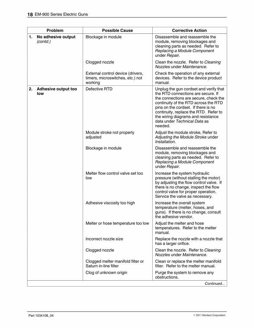
Problem Possible Cause Corrective Action
1. No adhesive output(contd.)
Blockage in module Disassemble and reassemble themodule, removing blockages andcleaning parts as needed. Refer toReplacing a Module Componentunder Repair.
Clogged nozzle Clean the nozzle. Refer to CleaningNozzles under Maintenance.
External control device (drivers,timers, microswitches, etc.) notworking
Check the operation of any externaldevices. Refer to the device productmanual.
2. Adhesive output toolow
Defective RTD Unplug the gun cordset and verify thatthe RTD connections are secure. Ifthe connections are secure, check thecontinuity of the RTD across the RTDpins on the cordset. If there is nocontinuity, replace the RTD. Refer tothe wiring diagrams and resistancedata under Technical Data asneeded.
Module stroke not properlyadjusted
Adjust the module stroke, Refer toAdjusting the Module Stroke underInstallation.
Blockage in module Disassemble and reassemble themodule, removing blockages andcleaning parts as needed. Refer toReplacing a Module Componentunder Repair.
Melter flow control valve set toolow
Increase the system hydraulicpressure (without stalling the motor)by adjusting the flow control valve. Ifthere is no change, inspect the flowcontrol valve for proper operation.Service the valve as necessary.
Adhesive viscosity too high Increase the overall systemtemperature (melter, hoses, andguns). If there is no change, consultthe adhesive vendor.
Melter or hose temperature too low Adjust the melter and hosetemperatures. Refer to the meltermanual.
Incorrect nozzle size Replace the nozzle with a nozzle thathas a larger orifice.
Clogged nozzle Clean the nozzle. Refer to CleaningNozzles under Maintenance.
Clogged melter manifold filter orSaturn in‐line filter
Clean or replace the melter manifoldfilter. Refer to the melter manual.
Clog of unknown origin Purge the system to remove anyobstructions.
Continued...

EM-900 Series Electric Guns 19
Part 1034108_04� 2011 Nordson Corporation
Troubleshooting (contd)
Problem Possible Cause Corrective Action
3. Adhesive output toohigh
Defective RTD Unplug the gun cordset and verify thatthe RTD connections are secure. Ifthe connections are secure, check thecontinuity of the RTD across the RTDpins on the cordset. If there is nocontinuity, replace the RTD. Refer tothe wiring diagrams under TechnicalData as needed.
Module stroke not properlyadjusted
Adjust the module stroke, Refer toAdjusting the Module Stroke underInstallation.
Melter flow control valve set toohigh
Decrease the system hydraulicpressure using the flow control valve.If there is no change, inspect the flowcontrol valve for proper operation.Service the valve as necessary.
Adhesive viscosity too low Decrease the overall systemtemperature (melter, hoses, andguns). If there is no change, consultthe adhesive vendor.
Melter or hose temperature toohigh
Adjust the melter and hosetemperatures. Refer to the meltermanual.
Incorrect nozzle size Replace the nozzle with a nozzle thathas a smaller orifice.
4. Erratic temperaturereadings
Incorrect system voltage Ensure that system voltages match.
CAUTION! The gun heater voltagemust match the hose voltage and thegun coil voltage must match thevoltage of the external control device.If these voltages do not match,serious damage will occur. Voltagespecifications are stamped on the gunnameplate cover.
Incorrect component wiring Check all wires and wire terminationsin the hose heater, output connector,and RTD circuit and repair as needed.Refer to the wiring diagrams underTechnical Data as needed.
Continued...

EM-900 Series Electric Guns20
Part 1034108_04 � 2011 Nordson Corporation
Problem Possible Cause Corrective Action
4. Erratic temperaturereadings (contd.)
Defective RTD Unplug the gun cordset and verify thatthe RTD connections are secure. Ifthe connections are secure, check thecontinuity of the RTD across the RTDpins on the cordset. If there is nocontinuity, replace the RTD. Refer tothe wiring diagrams under TechnicalData as needed.
5. Gun fails to heat Poor electrical connections Check all wires and wire terminationsin the hose heater, output connector,and RTD circuit and repair as needed.Refer to the wiring diagrams underTechnical Data as needed. With thesystem power off, disconnect thehose cordsets from the melter andgun. Check for heater and RTDcontinuity through the wires to gun.Also check each heater from wire toground to ensure that a wire is notgrounded. Replace the hose if thereis no continuity or if a heater wire isgrounded.
Incorrect system settings Verify system settings. Refer to themelter manual.
Defective heater or RTD Check the resistance of the RTD andheater across the appropriate pins onthe gun cordset. If the resistance isnot correct, replace the RTD orheater. Refer to the wiring diagramsand resistance data under TechnicalData as needed.
Failure in temperature control unit Check the operation of the melter ortemperature control unit. Refer to theappropriate product manual.
6. Gun overheats Incorrect system voltage Ensure that system voltages match.
CAUTION! The gun heater voltagemust match the hose voltage and thegun coil voltage must match thevoltage of the external control device.If these voltages do not match,serious damage will occur. Voltagespecifications are stamped on the gunnameplate cover.
Temperature settings too high Check the component temperaturesettings.
Continued...

EM-900 Series Electric Guns 21
Part 1034108_04� 2011 Nordson Corporation
Troubleshooting (contd)
Problem Possible Cause Corrective Action
6. Gun overheats(contd.)
Defective RTD Unplug the gun cordset and verify thatthe RTD connections are secure. Ifthe connections are secure, check thecontinuity and resistance of the RTDacross the RTD pins on the cordset. Ifthere is no continuity, replace theRTD. Refer to the wiring diagramsunder Technical Data as needed.
7. Gun heats slowly Incorrect system voltage Ensure that system voltages match.
CAUTION! The gun heater voltagemust match the hose voltage and thegun coil voltage must match thevoltage of the external control device.If these voltages do not match,serious damage will occur. Voltagespecifications are stamped on the gunnameplate cover.
Incorrect component wiring Check all wires and wire terminationsin the hose heater, output connector,and RTD circuit and repair as needed.Refer to the wiring diagrams underTechnical Data as needed.
Failed heater(s) Check the resistance of the heateracross the appropriate pins on thegun cordset. If the resistance is notcorrect, replace the heater. Refer tothe wiring diagrams and resistancedata under Technical Data asneeded.
8. Module seat leaks Module stroke not properlyadjusted
Adjust the module stroke. Refer toAdjusting the Module Stroke underInstallation.
Blockage in module Disassemble and reassemble themodule, removing blockages andcleaning parts as needed. Refer toReplacing a Module Componentunder Repair.
Continued...

EM-900 Series Electric Guns22
Part 1034108_04 � 2011 Nordson Corporation
Problem Possible Cause Corrective Action
9. Gun will not trigger -adhesive will notdispense
Gun not heating correctly See above.
Poor electrical connections Check all wires and wire terminationsin the hose heater, output connector,and RTD circuit and repair as needed.With system power off, disconnect thehose cordsets from the melter andgun. Check the heater and RTDcontinuity. Also check each heaterthrough wire to ensure the wire is notgrounded. Replace the hose if thereis no continuity or if a heater wire isgrounded.
Incorrect component wiring Check all wires and wire terminationsin the hose heater, output connector,and RTD circuit and repair as needed.Refer to the wiring diagrams underTechnical Data as needed.
Defective coil Unplug the gun cordset and check thecoil resistance across the coil pins onthe cordset. Refer to the wiringdiagrams and resistance data underTechnical Data as needed.
Module stroke not properlyadjusted
Adjust the module stroke. Refer toAdjusting the Module Stroke underInstallation.
Blockage in module or nozzle Disassemble and reassemble themodule, removing blockages andcleaning parts as needed. Refer toReplacing a Module Componentunder Repair.
Adhesive viscosity too high Increase the overall systemtemperature (melter, hoses, andguns). If there is no change, consultthe adhesive vendor.
External control device (drivers,timers, microswitches, etc.) notworking
Check the operation of the externalcontrol device. Ensure that the wiringconnections are correct. Refer to thedevice manual.
System not up to operatingtemperature
Allow system to heat. Refer to themelter manual for other relatedproblems.
Continued...

EM-900 Series Electric Guns 23
Part 1034108_04� 2011 Nordson Corporation
Problem Possible Cause Corrective Action
10. Poor adhesive cutoff Module stroke not properlyadjusted
Adjust the module stroke. Refer toAdjusting the Module Stroke underInstallation.
Blockage in module Disassemble and reassemble themodule, removing blockages andcleaning parts as needed. Refer toReplacing a Module Componentunder Repair.
Incorrect distance from substrate Verify mounting of the gun foradequate bead placement.
Incorrect nozzle type or size Some nozzles require extra warm‐uptime or have poor cutoff when the gunis mounted horizontally. Contact aNordson representative forassistance with the application.
System pressure incorrect Adjust pressure up or down untildesired performance is achieved.
Adhesive viscosity too high Increase the overall systemtemperature (melter, hoses, andguns). If there is no change, consultthe adhesive vendor.
Nozzle loose Verify that the nozzle is secure.Adjust or replace as needed.
External control device (drivers,timers, microswitches, etc.) notworking or operating incorrectly
Check the operation of the externalcontrol device. Refer to the devicemanual.
11. Excessive residue Nozzle leaking Clean or replace if necessary.
Incorrect nozzle type or size Some nozzles require extra warm‐uptime or have poor cutoff when the gunis mounted horizontally. Contact aNordson representative forassistance with the application.
Nozzle loose Verify that the nozzle is secure.Adjust or replace as needed.
Incorrect distance from substrate Verify mounting of the gun foradequate bead placement.

EM-900 Series Electric Guns24
Part 1034108_04 � 2011 Nordson Corporation
Repair Troubleshooting activities may identify needed repairs. Use these repairprocedures as appropriate. Refer to Parts for component part numbers.
WARNING! Allow only personnel with appropriate training and experience tooperate or service the equipment. The use of untrained or inexperiencedpersonnel to operate or service the equipment can result in injury, includingdeath, to themselves and others, and damage to the equipment.
WARNING! Read and follow all procedures as detailed in the Safety sectionbefore engaging in any repairs. Falure to do so can result in injury, includingdeath, to themselves and others, and damage the equipment.
CAUTION! Always disconnect the gun electrical connector when performingmaintenance to prevent accidental triggering.
Before proceeding with any maintenance procedure:
1. Electric System: Turn off the melter pump motor.Pneumatic System: Completely relieve the system hydraulic pressure.
2. Verify that the EM‐900 gun is positioned over a waste receptacle.
3. Electric System:
� Switch the gun head open several times using the TEST switch to
ensure that the pressure in the hose and gun head is relieved.
� Remove the electric power from the melter, and disconnect the
electric connector to the gun.
Pneumatic System:
� Disable the gun by turning off or disconnecting the gun from its
triggering device (pattern controller, timer, PLC, etc.).
Replacing a Module
Follow this procedure to replace a complete module. To replace a modulecomponent that requires complete disassembly and reassembly of themodule, refer to Replacing a Module Component. To replace only the coiland housing assembly, refer to Replacing the Coil and Housing Assembly.Refer to Parts for replacement module part numbers.
Remove a Module
See Figure 12.
1. De‐energize the system and disable the guns. Refer to Safety.
2. Remove the nozzle (5).

4210056A
12
3 4
5
6
EM-900 Series Electric Guns 25
Part 1034108_04� 2011 Nordson Corporation
3. Remove the screws (3) that secure the module to the manifold. If themodule is tightly clamped between other modules, loosen the adjacentmodules.
4. Grasp the module at the top and bottom and carefully pull the moduleaway from the gun to disconnect the coil pins (2). If the module resists,lightly tap the coil until the module breaks free.
CAUTION! Do not rotate module. Damage to pins may result.
5. Wipe off dripping adhesive from the manifold face. Do not allow theadhesive to drip into the electrical connector.
Install a Module
See Figure 12.
1. Ensure that the coil pin seal (1) is in place.
2. Ensure that the O‐ring (5) is in good condition and in place.
3. Engage the coil pins (2) in the connector block on the gun manifold andsecure the module with the screws (4) removed previously.
4. Energize the system and allow the module to warm up for 10 minutes.
5. After the module is at operating temperature, adjust the module stroke asneeded. Refer to Adjusting the Module Stroke under Installation.
Figure 12 Module replacement
1. Coil pin seal
2. Coil pins
3. Ground pin
4. Module screw
5. O‐ring
6. Nozzle

4210010A
0970442a
3
1
2
4
EM-900 Series Electric Guns26
Part 1034108_04 � 2011 Nordson Corporation
Replacing a Coil and Housing Assembly
Follow this procedure to replace only the coil and housing assembly on amodule. To replace a complete module, refer to Replacing a Module. Toreplace a module component that requires complete disassembly andreassembly of the module, refer to Replacing a Module Component. Refer toParts for coil and housing kit part numbers.
See Figure 13.
1. De‐energize the system and disable the guns. Refer to Safety.
2. Remove the module on which the coil and housing assembly are to bereplaced. Refer to To Remove a Module under Replacing a Module.
3. Remove the retaining nut (1).
4. Pull coil and housing assembly (2) away from the module body (3),sliding it up the guide tube (4).
5. Install the new coil and housing assembly in the module body, slipping itover the guide tube.
6. Install the retaining nut.
7. Install the module on the gun. Refer to To Install a Module underReplacing a Module.
Figure 13 Coil replacement
1. Retaining nut
2. Coil and housing assembly
3. Module body
4. Guide tube

4210011A
0970
478c
1
2
3
4
56
7
8
9
10
11
12
EM-900 Series Electric Guns 27
Part 1034108_04� 2011 Nordson Corporation
Replacing a Module Component
Follow these procedures to replace (or clean) a module component thatrequires complete disassembly and reassembly of the module. To replace acomplete module, refer to Replacing a Module . To replace only the coil andhousing assembly, refer to Replacing the Coil and Housing Assembly. Referto Parts for module rebuild kit part numbers.
Disassemble the Module
See Figure 14.
1. Heat the system to application temperature. The adhesive in the modulemust be molten for this procedure.
2. De‐energize the system and disable the gun. Refer to Safety.
3. Remove the module on which a component is to be replaced. Refer toRemove a Module under Replacing a Module.
4. Loosen the retaining nut (1).
CAUTION! Failure to back the armature off of the seat may damage both theseat and armature when the seat is reinstalled.
5. To back the armature off of the seat, turn the coil end of the guide tubecounterclockwise until it stops turning.
6. Pull the coil and housing (2) from module body (6).
7. Remove the seat (12), armature (10), and spring (9).
8. Clamp the module body in a vice.
CAUTION! Do not use pliers to turn the guide tube. Pliers will damage thefine threads and deform the tube wall.
9. With a screwdriver, turn the guide tube (8) clockwise until it comes loose(about 12 turns).
10. Push down on the top of the guide tube until it can be pulled free from thebottom of the module body.
11. As needed, clean the module components by placing them in a containerof Nordson Type R fluid heated to 245 �C (475�F). Allow thecomponents to soak for 10 minutes, then remove them and blow offexcess residue with an air gun or wipe them with a shop rag.
Figure 14 Module disassembly
1. Retaining nut
2. Coil and housing assembly
3. Coil pin seal
4. Coil pin
5. O‐ring
6. Module body
7. O‐ring
8. Guide tube
9. Spring
10. Armature
11. O‐ring
12. Seat

4210011A
0970
478c
1
2
3
4
56
7
8
9
10
11
12
EM-900 Series Electric Guns28
Part 1034108_04 � 2011 Nordson Corporation
Reassemble the Module
See Figure 15. Where applicable in this procedure, install new modulecomponents.
1. Lubricate a new O‐ring (5) and install it in the groove in the top of themodule body.
CAUTION! Failure to screw the guide tube fully into the module body willresult in damage to the armature and seat due to lack of stroke clearance.
2. Lubricate the top threads of the guide tube (8) with high temp silicone.Carefully pass the top threads through the O‐ring by rotating it clockwise.Push the guide tube through until the threads engage, and screw theguide tube fully into the module body.
3. Install the spring (9), armature (10), O‐ring (11), and seat (12). Lubricatethe O‐ring.
4. Install the coil and housing assembly (2) on the module body, slipping itover the guide tube. Note the location of the coil pins (4).
5. Install the retaining nut (1).
6. Lubricate and install the module body O‐ring (7). Replace the O‐ring ifthe existing one is worn or damaged.
7. Ensure that the coil pin seal (3) is in place.
8. Install the module on the gun. Refer to Install a Module under Replacinga Module.
Figure 15 Module reassembly
1. Retaining nut
2. Coil and housing assembly
3. Coil pin seal
4. Coil pin
5. O‐ring
6. Module body
7. O‐ring
8. Guide tube
9. Spring
10. Armature
11. O‐ring
12. Seat

4210057A
1
2
3 4
EM-900 Series Electric Guns 29
Part 1034108_04� 2011 Nordson Corporation
Replacing the Coil Connector
Follow this procedure to replace the electrical connector (terminal block) forthe module coil. Refer to Parts for the coil connector kit part number.
1. De‐energize the system and disable the gun. Refer to Safety.
2. Remove the module(s) from the gun. Refer to To Remove a Moduleunder Replacing a Module.
See Figure 16.
3. Place a shop cloth over the coil connector to prevent adhesive fromgetting into the connector. Replace the coil seal if it becomes damaged;otherwise, contamination of the connector will result.
4. Remove the manifold cover and gasket . If the gasket is broken, replaceit.
5. Loosen the connector socket screws and remove the wires.
6. Remove the connector mounting screws and then remove the connector.
7. If necessary, cut the connector wires back to the insulation and re‐stripthem to 4 mm (0.19 in.).
8. Insert the connector wires into the screw‐clamp sockets and tighten thescrews.
9. Press the connector into the slot in the manifold and reinstall themounting screws.
Figure 16 Coil connectorreplacement
1. Socket screw
2. Coil connector
3. Mounting screw
4. Wires
10. Check the screw‐clamp terminations and tighten as necessary.
11. Reinstall the gasket and manifold cover plate.

EM-900 Series Electric Guns30
Part 1034108_04 � 2011 Nordson Corporation
Blocking a Module Port
Unused module ports on the gun manifold may be covered by a blockingplate. Refer to Parts for the blocking kit part number.
See Figure 17.
1. De‐energize the system and disable the guns. Refer to Safety.
2. If applicable, remove the module from the port to be blocked off. Refer toTo Remove a Module under Replacing a Module.
3. Coat the blocking kit O‐rings (1, 2) with O‐ring lubricant.
4. Install the O‐rings (1, 2) on the inside of the blocking plate (3).
NOTE: The smaller O‐ring (1) seals the adhesive passage at the exit ofthe manifold. The larger O‐ring (2) surrounds the area that houses thecoil connector.
5. Use the screws (4) from the kit to secure the blocking plate to themanifold.
4210013A
21
3
4
Figure 17 Module blocking kit components
1. Small O‐ring
2. Large O‐ring
3. Blocking plate
4. Screw

4210058A
1
2
3
EM-900 Series Electric Guns 31
Part 1034108_04� 2011 Nordson Corporation
Replacing a Heater
Follow this procedure to replace a heater. Guns may have one to fourheaters, depending on their size. Refer to Parts for heater replacement kitpart numbers.
1. De‐energize the system and disable the gun. Refer to Safety.
2. Remove the manifold cover and gasket, and disconnect the heater wires(1).
3. Gently push the old heater (2) out of the manifold by inserting a rod in theheater bore on the back of the manifold (3).
4. Cut the new heater wires to match the length of the old heater wires.
5. Strip the new heater wires to 6 mm (0.250 in.).
6. Apply heater lubricant to the new heater and slide it into the heater bore.
7. Connect the heater wires to the terminal block.
NOTE: Refer to Technical Data at the end of this manual for wiringdiagrams.
8. Install the gasket and manifold cover.
Figure 18 Heater replacement
1. Heater wires
2. Heater
3. Manifold

4210059A
2
1
EM-900 Series Electric Guns32
Part 1034108_04 � 2011 Nordson Corporation
Replacing an RTD
To ensure proper temperature control, replace an RTD as a complete unit,with soldered gold contact pins and shielded wires. Refer to Parts for theRTD replacement kit part number.
1. Disconnect and lock out electrical power to the melter system.
2. Disconnect the gun electrical connector.
3. Access the gun electrical cavity.
4. Cut the leads of the defective RTD (1) approximately 25 mm (1 in.) fromthe RTD element (2).
5. Remove and discard the defective RTD element.
6. Strip about 6 mm (0.25 in.) of insulation from the old RTD leads.
7. Cut the heat shrink tubing from the kit in half (into two 25‐mm [1‐in.]pieces) and slide a piece of heat shrink tubing onto each of the oldRTD�leads.
8. Cut the new RTD leads about 50-76 mm (2-3 in.) from the RTD�elementand strip about 6 mm (0.25 in.) of the insulation from the new RTD leads.
9. Use a parallel wire splice to crimp the exposed wire of one old and onenew RTD lead together. Repeat for the other old and new RTD leads.
4201105A
RTD
2
1
3
4
Figure 19 Splicing RTD leads
1. Old RTD lead
2. Heat shrink tubing
3. Parallel wire splice
4. New RTD lead

4210017A
1
2
EM-900 Series Electric Guns 33
Part 1034108_04� 2011 Nordson Corporation
Replacing an RTD (contd)
10. Slide the heat shrink tubing over the splices and heat it to shrink thetubing around the splices.
11. Install the new RTD in the manifold.
12. If the knockout hole was used to remove the old RTD, seal it with asilicone sealant.
13. Route the RTD wires through the armored conduit and back shell. Pushthe gold pins into positions 4 and 5 on the back shell. Pull the pins intotheir final positions such that they click into place.
14. Reassemble the conduit and tighten the set screws. On water‐resistantguns, seal the set screws with a silicone sealant.
15. Inspect the gasket and replace it if it is damaged.
16. Install gasket and manifold cover.
Replacing a Nozzle
Follow this procedure to replace a nozzle. The adhesive in the system mustbe heated to application temperature before a nozzle is removed.
See Figure 20.
1. Heat the system to application temperature.
2. Relieve system pressure and disable the gun. Refer to Safety.
3. Use a a 17 mm (11/16 in.) wrench to hold the module seat (2) stationaryand use a 14 mm (9/16 in.) wrench to remove the nozzle (2).
4. Clean adhesive char from the face of the module seat.
5. Install the new nozzle.
Figure 20 Nozzle replacement
1. Module seat
2. Nozzle

EM-900 Series Electric Guns34
Part 1034108_04 � 2011 Nordson Corporation
Parts To order parts, call the Nordson Customer Service Center or your localNordson representative. Use these five‐column parts lists, and theaccompanying illustrations, to describe and locate parts correctly. Thefollowing chart provides guidance for reading the parts lists.
The number in the Item column corresponds to the circled item numberin the parts list illustration. A dash in this column indicates that the item isan assembly.
The number in the Part column is the Nordson part numberyou can use to order the part. A series of dashes indicatesthat the part is not saleable. In this case, you must ordereither the assembly in which the part is used or a service kitthat includes the part.
The Description column describes the part andsometimes includes dimensions or specifications.
The Note column contains letters that refer to notes atthe bottom of the parts list. These notes provide kitpart numbers and other key information.
The Quantity column tells you how many of the part isused to manufacture the assembly shown in the partslist illustration. A dash in this column indicates that theamount of the item required in the assembly is notquantifiable.
Item Part Description Quantity Note
— 0000000 Assembly A 1
1 000000 � Part of assembly A 2 A
2 ‐ ‐ ‐ ‐ ‐ ‐ � � Part of item 1 1
3 0000000 � � � Part of item 2 —
NS 000000 � � � � Part of item 3 2
NOTE A: Important information about item 1
AR: As Required
NS: Not Shown

EM-900 Series Electric Guns 35
Part 1034108_04� 2011 Nordson Corporation
Gun Assemblies
EM‐901
Part Number Description
1033392 Gun, EM‐901, SE, 120V HTR, 120VAC Coil, 120 OH
1033393 Gun, EM‐901, SE, 120V HTR, 120VDC Coil, 120 OH
1033395 Gun, EM‐901, SE, 200V HTR, 120VAC Coil, 120 OH
1033398 Gun, EM‐901, SE, 240V HTR, 120VAC Coil, 120 OH
1033399 Gun, EM‐901, SE, 240V HTR, 240VAC Coil, 120 OH
1033400 Gun, EM‐901, SE, 240V HTR, 120VDC Coil, 120 OH
1033401 Gun, EM‐901, SE, 240V HTR, 240VDC Coil, 120 OH
1033404 Gun, EM‐901, TE, 120V HTR, 120VAC Coil, 120 OH
1033406 Gun, EM‐901, TE, 200V HTR, 120VAC Coil, 120 OH
1033407 Gun, EM‐901, TE, 200V HTR, 200VAC Coil, 120 OH
1033412 Gun, EM‐901, TE, 240V HTR, 120VAC Coil, 120 OH
1033413 Gun, EM‐901, TE, 240V HTR, 240VAC Coil, 120 OH
1033414 Gun, EM‐901, TE, 240V HTR, 120VDC Coil, 120 OH
1033415 Gun, EM‐901, TE, 240V HTR, 240VDC Coil, 120 OH
EM‐902
Part Number Description
1033881 Gun, EM‐902, SE, 240V HTR, 120VAC Coil, 120 OH
1033882 Gun, EM‐902, SE, 240V HTR, 240VAC Coil, 120 OH
1033883 Gun, EM‐902, SE, 240V HTR, 120VDC Coil, 120 OH
1033884 Gun, EM‐902, SE, 240V HTR, 240VDC Coil, 120 OH
1033889 Gun, EM‐902, TE, 240V HTR, 240VAC Coil, 120 OH
EM‐903
Part Number Description
1033900 Gun, EM‐903, TE, 240V HTR, 240VDC Coil, 120 OH
1033890 Gun, EM‐903, SE, 240V HTR, 240VDC Coil, 120 OH
EM‐904
Part Number Description
1033885 Gun, EM‐904‐T‐LP‐SE, 1.0CTRS,CA 120VAC VLV
1033886 Gun, EM‐904‐T‐LP‐SE, 1.0CTRS,CA 240VAC VLV
1033887 Gun, EM‐904‐T‐LP‐SE, 1.0CTRS, 120VDC VLV
1033888 Gun, EM‐904‐T‐LP‐SE, 1.0CTRS, 240VDC VLV
1033902 Gun, EM‐904‐T‐LP‐TE, 1.0CTRS, 240VDC VLV
1033903 Gun, EM‐906, TE, 240VDC

EM-900 Series Electric Guns36
Part 1034108_04 � 2011 Nordson Corporation
Gun Parts
Item Part Description Quantity Note
1 986295 Screw, socket, 6‐32 X 1.25, BL 4
2 1036055 Cordset, water wash w/eyelet and RTD, EM‐901 1 A
2 1036129 Cordset, water wash w/eyelet and RTD, EM‐902,EM‐903, EM‐904, EM‐906
1 A
3 ------ Cable block 1
4 ------ Gasket with cutout 1
5 1022334 Terminal block, 2 pos 1
6 ------ Heater assy 1 A
7 972628 Connector, hose, 9/16‐18 1
8 ------ Manifold (side port shown) 1
9 ------ Gasket 1
10 ------ Cover 1
11 ------ Screw, but hd, socket, 6‐32 X 1/4, ZP, grade 5 7
12 ------ Module 1 B
13 ------ Spacer, .750 OD X .328 ID X .12 THK 4
14 983504 Washer, flat, E, .281 X .734 X .063, ZN 2
15 981222 Screw, hex, 1/4‐20 X 1.500, cap, ZN 2
16 ------ Socket, module ground pin 1
17 983102 Washer, lock, E, spt, #6, stl, ZN 1
18 ------ Screw, but. hd, soc, #4‐40 X .188, bl, G8 1
19 ------ Connector block assy, 3 pos 1
NOTE A: See Table 5 for RTD and Heater Assy order information
B: See Table 4 for Module order information

EM-900 Series Electric Guns 37
Part 1034108_04� 2011 Nordson Corporation
Gun Parts (contd)
1
2
3
54
11
19
1816
6
11
17
8
12
15
14
13
11
97
10
4210060A
Figure 21 Exploded View of EM-900 gun (EM-901 rear entry gun shown)

EM-900 Series Electric Guns38
Part 1034108_04 � 2011 Nordson Corporation
Replacement Modules for EM‐900 Guns
See Figure 22.
Table 4 Module and Module Parts
Item Part Description Quantity Note
1 1032414 Kit, module, EM‐900, 120 VAC — A
1032415 Kit, module, EM‐900, 200 VAC — A
1032416 Kit, module, EM‐900, 240 VAC — A
NOTE: The modules below require a DC Gun Driver for proper operation.
Item Part Description Quantity Note
1032417 Kit, module, EM‐900, 120 VDC — A
1032418 Kit, module, EM‐900, 200 VDC — A
1032419 Kit, module, EM‐900, 240 VDC — A
2 984444 Nut, lock, 3/8‐32 x 0.093 1
3 1029802 Kit, coil and housing assembly, 120 V 1
1029803 Kit, coil and housing assembly, 200 V 1
1029804 Kit, coil and housing assembly, 240 V 1
4 1027905 Seal, coil 1 B
5 940073 O‐ring, Viton, 0.145 ID x 0.070 W in. 1 B
NOTE A: Order this part for a complete replacement module.
B: This part is included in the coil and housing assembly kit (item 3).
4210018A
0980017
1
2
3
4
5
Figure 22 Module parts

EM-900 Series Electric Guns 39
Part 1034108_04� 2011 Nordson Corporation
Module Rebuild Kits
See Figure 23.
Item Part Description Quantity
— 1029811 Kit, module body —
1 984444 � Nut, lock, 3/8‐32 x 0.093 1
2 1027905 � Seal, coil 1
3 940121 � O‐ring, Viton, 0.364 ID x 0.070 W in. 1
4 ‐ ‐ ‐ ‐ ‐ ‐ � Body, module 1
5 981975 � Screw, socket, cap, 10‐32 x 1.125 in. 2
6 940073 � O‐ring, Viton, 0.145 ID x 0.070 W in. 1
— 1033136 Kit, guide tube —
1 984444 � Nut, lock, 3/8‐32 x 0.093 1
2 1027905 � Seal, coil 1
3 940121 � O‐ring, Viton, 0.364 ID x 0.070 W in. 1
6 940073 � O‐ring, Viton, 0.145 ID x 0.070 W in. 1
7 ‐ ‐ ‐ ‐ ‐ ‐ � Tube, guide 1
10 940133 � O‐ring, Viton, 0.426 ID x 0.070 W in. 1
— 1029809 Kit, armature and seat, AC —
1 984444 � Nut, lock, 3/8‐32 x 0.093 1
2 1027905 � Seal, coil 1
3 940121 � O‐ring, Viton, 0.364 ID x 0.070 W in. 1
5 981975 � Screw, socket, cap, 10‐32 x 1.125 in. 2
6 940073 � O‐ring, Viton, 0.145 ID x 0.070 W in. 1
8 987073 � Spring, compression, 0.75 x 0.13 x 0.02 in. 1
9 ‐ ‐ ‐ ‐ ‐ ‐ � Armature 1
10 940133 � O‐ring, Viton, 0.426 ID x 0.070 W in. 1
11 ‐ ‐ ‐ ‐ ‐ ‐ � Seat, with insert 1
— 1029810 Kit, armature and seat, DC —
1 984444 � Nut, lock, 3/8‐32 x 0.093 1
2 1027905 � Seal, coil pin 1
3 940121 � O‐ring, Viton, 0.364 ID x 0.070 W in. 1
5 981975 � Screw, socket, cap, 10‐32 x 1.125 in. 2
6 940073 � O‐ring, Viton, 0.145 ID x 0.070 W in. 1
8 ‐ ‐ ‐ ‐ ‐ ‐ � Spring, stainless, 8 lb 1
9 ‐ ‐ ‐ ‐ ‐ ‐ � Armature 1
10 940133 � O‐ring, Viton, 0.426 ID x 0.070 W in. 1
11 ‐ ‐ ‐ ‐ ‐ ‐ � Seat 1
Continued...

EM-900 Series Electric Guns40
Part 1034108_04 � 2011 Nordson Corporation
Item QuantityDescriptionPart
— 1029812 Kit, O‐rings and spring, AC —
3 940121 � O‐ring, Viton, 0.364 ID x 0.070 W in. 4
6 940073 � O‐ring, Viton, 0.145 ID x 0.070 W in. 4
8 987073 � Spring, compression, 0.75 x 0.13 x 0.02 in. 4
10 940133 � O‐ring, Viton, 0.426 ID x 0.070 W in. 4
— 1029813 Kit, O‐rings and spring, DC —
3 940121 � O‐ring, Viton, 0.364 ID x 0.070 W in. 1
6 940073 � O‐ring, Viton, 0.145 ID x 0.070 W in. 1
8 1027914 � Spring, stainless, 8 lb 1
10 940133 � O‐ring, Viton, 0.426 ID x 0.070 W in. 1
4210019A
0970441
1
2
3
4
5
6
7
8
9
10
11
Figure 23 Module rebuild kit parts

EM-900 Series Electric Guns 41
Part 1034108_04� 2011 Nordson Corporation
Heater and RTD Kits
Table 5 Heater and RTD Kits
Part Description Quantity Note
1029814 Kit, heater, EM‐901, 115 V, 150 W, 57.15�mm (2.25�in.) AR A
1029815 Kit, heater, EM‐901, 200 V, 150 W, 57.15�mm (2.25�in.) AR A
1029816 Kit, heater, EM‐901, 230 V, 150 W, 57.15�mm (2.25�in.) AR A
1029817 Kit, heater, EM‐902-904, 115 V, 150 W, 60.33�mm (2.375 in.) AR A
1029818 Kit, heater, EM‐902-904, 200 V, 150 W, 60.33�mm (2.375 in.) AR A
1029819 Kit, heater, EM‐902-904, 230 V, 150 W, 60.33�mm (2.375 in.) AR A
1029830 Kit, heater, EM‐902-904, 115 V, 200 W, 60.33�mm (2.375 in.) AR A
1029831 Kit, heater, EM‐902-904, 200 V, 200 W, 60.33�mm (2.375 in.) AR A
1029832 Kit, heater, EM‐902-904, 230 V, 200 W, 60.33�mm (2.375 in.) AR A
1018964 Kit, RTD replacement AR
NOTE A: All heater kits contain two heaters. Some guns require only one heater and some require four or more.
AR: As Required
Filter Kits
Part Description
1007033 Filter, Saturn, in‐line, 50 mesh assembly
1007233 Filter, Saturn, in‐line, 50 mesh, 45° assembly
1007230 Filter, Saturn, in‐line, 50 mesh, 90° assembly
1007036 Filter, Saturn, in‐line, 50 mesh, 2 pack
1007372 Filter, Saturn, in‐line, 50 mesh, 5 pack
1007034 Filter, Saturn, in‐line, 100 mesh assembly
1007234 Filter, Saturn, in‐line, 100 mesh, 45° assembly
1007231 Filter, Saturn, in‐line, 100 mesh, 90° assembly
1007037 Filter, Saturn, in‐line, 100 mesh, 2 pack
1007373 Filter, Saturn, in‐line, 100 mesh, 5 pack
1007035 Filter, Saturn, in‐line, 200 mesh assembly
1007235 Filter, Saturn, in‐line, 200 mesh, 45° assembly
1007232 Filter, Saturn, in‐line, 200 mesh, 90° assembly
1007038 Filter, Saturn, in‐line, 200 mesh, 2 pack
1007374 Filter, Saturn, in‐line, 200 mesh, 5 pack

EM-900 Series Electric Guns42
Part 1034108_04 � 2011 Nordson Corporation
Driver Cable Assemblies
Part Description Note
1046343 EM‐900 Series signal cable, 4.6 m (15 ft), 115V Standard Nordson Hose
1046344 EM‐900 Series signal cable, 9.1 m (30 ft), 115V Standard Nordson Hose
1032902 EM‐900 Series signal cable. 4.6 m (15 ft), 230V Standard Nordson Hose
1032904 EM‐900 Series signal cable, 9.1 m (30 ft), 230V Standard Nordson Hose
1032447 EM‐900 Series signal cable. 4.6 m (15 ft), 230V Nordson Water Wash Hose
1032448 EM‐900 Series signal cable, 9.1 m (30 ft), 230V Nordson Water Wash Hose
EM Series Gun Drivers
HD2A, HD2B, and HD4A gun drivers enhance the performance of automaticguns by producing extremely fast valve action for up to 8 guns per valvegroup. The HD gun drivers ensure precise adhesive deposition by deliveringhigh voltage DC power to the electric applicator coils, providing sharpercutoff and increased pattern placement accuracy. Contact a Nordsonrepresentative for information on ordering gun drivers.
Part Number Description
1029760 Gun Driver, HD‐2A
1029761 Gun Driver, HD‐2B
1029762 Gun Driver. HD‐4A
1033756 Gun Driver replacement kit (HD2A, HD4A)
1034536 Gun Driver replacement kit (HD2B)
1037842 Fuse replacement

EM-900 Series Electric Guns 43
Part 1034108_04� 2011 Nordson Corporation
Extrusion Nozzles
The following extrusion nozzles may be used with EM‐900 guns.
Straight Nozzles
See Figure 24. All straight nozzles have one orifice. In the following table,D�stands for the diameter of the orifice and L stands for the length of theadhesive passage (also known as the engagement).
Part Description Note
1026682 Nozzle, straight, 0.016 in. D/0.300 L
1026683 Nozzle, straight, 0.018 in. D/0.300 L
1026684 Nozzle, straight, 0.020 in. D/0.300 L
1026685 Nozzle, straight, 0.025 in. D/0.300 L
1026686 Nozzle, straight, 0.035 in. D/0.300 L
1026687 Nozzle, straight, 0.050 in. D/0.300 L
1026688 Nozzle, straight, 0.008 in. D/0.050 L
1026689 Nozzle, straight, 0.010 in. D/0.050 L
1026700 Nozzle, straight, 0.012 in. D/0.050 L
1026701 Nozzle, straight, 0.010 in. D/0.075 L
1026702 Nozzle, straight, 0.012 in. D/0.075 L
1026703 Nozzle, straight, 0.014 in. D/0.075 L
1026704 Nozzle, straight, 0.016 in. D/0.075 L
1026705 Nozzle, straight, 0.018 in. D/0.075 L
1026706 Nozzle, straight, 0.020 in. D/0.075 L
1026707 Nozzle, straight, 0.012 in. D/0.150 L
1026708 Nozzle, straight, 0.018 in. D/0.150 L
1026709 Nozzle, straight, 0.020 in. D/0.150 L
1026710 Nozzle, straight, 0.025 in. D/0.150 L
1026711 Nozzle, straight, 0.030 in. D/0.150 L
1026712 Nozzle, straight, 0.035 in. D/0.150 L
1026713 Nozzle, straight, 0.040 in. D/0.150 L
4210038A
Figure 24 Straight nozzle
Right‐Angle Nozzles, One Orifice

EM-900 Series Electric Guns44
Part 1034108_04 � 2011 Nordson Corporation
See Figure 25.
Part Description Note
1026728 Nozzle, right‐angle, one orifice, 0.012 in.
1026729 Nozzle, right‐angle, one orifice, 0.014 in.
1026730 Nozzle, right‐angle, one orifice, 0.016 in.
1026731 Nozzle, right‐angle, one orifice, 0.018 in.
1026732 Nozzle, right‐angle, one orifice, 0.020 in.
1026733 Nozzle, right‐angle, one orifice, 0.025 in.
1026727 Nozzle, right‐angle, one orifice, 0.028 in.
1026734 Nozzle, right‐angle, one orifice, 0.030 in.
1026735 Nozzle, right‐angle, one orifice, 0.040 in.
1027389 Kit, screw and washer A
NOTE A: Includes 10 screws and 10 washers.
4210039A
Figure 25 Right-angle nozzle, one orifice
Right‐Angle Nozzles, Two Orifices
See Figure 26.
Part Description Note
1026736 Nozzle, right‐angle, two orifices, 0.014 in.
1026737 Nozzle, right‐angle, two orifices, 0.016 in.
1026738 Nozzle, right‐angle, two orifices, 0.018 in.
1026739 Nozzle, right‐angle, two orifices, 0.020 in.
1026740 Nozzle, right‐angle, two orifices, 0.025 in.
1026741 Nozzle, right‐angle, two orifices, 0.030 in.
1026742 Nozzle, right‐angle, two orifices, 0.040 in.
1027389 Kit, screw and washer A
NOTE A: Includes 10 screws and 10 washers.
4210043A
Figure 26 Right-angle nozzle, two orifices
Button Nozzles

EM-900 Series Electric Guns 45
Part 1034108_04� 2011 Nordson Corporation
See Figure 27.
Part Description Note
1026714 Nozzle, button, single, 0.020 in., 30‐degree
1026715 Nozzle, button, dual, 0.012 in., 30‐degree
1026716 Nozzle, button, dual, 0.016 in., 30‐degree
1026717 Nozzle, button, dual, 0.016 in., 90‐degree
1026718 Nozzle, button, dual, 0.018 in., 30‐degree
1026719 Nozzle, button, dual, 0.018 in., 45‐degree
1026720 Nozzle, button, dual, 0.020 in., 30‐degree
1026721 Nozzle, button, dual, 0.020 in., 45‐degree
1026722 Nozzle, button, dual, 0.025 in., 45‐degree
1026723 Nozzle, button, dual, 0.025 in., 90‐degree
1026724 Nozzle, button, triple, 0.020 in., 30‐degree
1026725 Nozzle, button, triple, 0.025 in., 60‐degree
1026726 Nozzle, button, quadruple, 0.020 in., 90‐ and45‐degree
4210042A
Figure 27 Button nozzles
Insert Nozzles
See Figure 28.
Part Description Note
1026743 Nozzle, insert, 90‐degree dual, 0.012 in.
1026744 Nozzle, insert, 90‐degree dual, 0.014 in.
1026745 Nozzle, insert, 90‐degree dual, 0.016 in.
4210040A
Figure 28 Insert nozzle
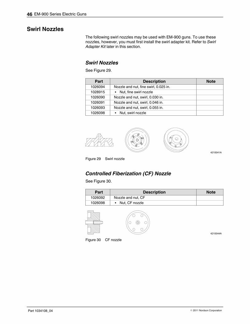
EM-900 Series Electric Guns46
Part 1034108_04 � 2011 Nordson Corporation
Swirl Nozzles
The following swirl nozzles may be used with EM‐900 guns. To use thesenozzles, however, you must first install the swirl adapter kit. Refer to SwirlAdapter Kit later in this section.
Swirl Nozzles
See Figure 29.
Part Description Note
1026094 Nozzle and nut, fine swirl, 0.025 in.
1028915 � Nut, fine swirl nozzle
1026090 Nozzle and nut, swirl, 0.030 in.
1026091 Nozzle and nut, swirl, 0.046 in.
1026093 Nozzle and nut, swirl, 0.055 in.
1026098 � Nut, swirl nozzle
4210041A
Figure 29 Swirl nozzle
Controlled Fiberization (CF) Nozzle
See Figure 30.
Part Description Note
1026092 Nozzle and nut, CF
1026098 � Nut, CF nozzle
4210044A
Figure 30 CF nozzle

EM-900 Series Electric Guns 47
Part 1034108_04� 2011 Nordson Corporation
Swirl Adapter Kit
See Figure 31. This kit can be used to adapt an EM‐900 gun for swirloperation.
Item Part Description Quantity Note
— 1026087 Kit, swirl, adapter, EM‐900 —
1 ‐ ‐ ‐ ‐ ‐ ‐ � Adapter, fluid 1
2 940161 � O‐ring, Viton, 0.614 ID x 0.070 W in. 1
3 1028848 � Collar, air 1
4 ‐ ‐ ‐ ‐ ‐ ‐ � Screw, socket, 4‐40 x 125 1
5 940101 � O‐ring, Viton, 0.239 ID x 0.070 W in. 1
6 971607 � Connector, 10‐32 x 1/4 in. 1
7 101887 � Clamp, tube, 0.228 in. 2
8 1028910 � Tubing, 1/4 OD x 1/8 ID in. 1.5
9 1028911 � Fitting, mini‐barb, 0.125 ID in. 1
10 ‐ ‐ ‐ ‐ ‐ ‐ � Seal, swirl adapter 1
11 ‐ ‐ ‐ ‐ ‐ ‐ � Adapter, swirl, EM‐900 1
12 900493 � Lubricant, O‐ring, high‐temperature —
13 222561 � Clamp, 1/4 Tee 1
4210037A
9 7
11
10 12
5
3
1
212
4
613
8
12
Figure 31 Swirl adapter kit parts
Hose Adapter Fittings

EM-900 Series Electric Guns48
Part 1034108_04 � 2011 Nordson Corporation
If a hose cannot be properly positioned using the straight hose connectorsupplied with the gun, then a 45� or 90� adapter fitting may be required.
Item Part Description Quantity
NS 1024081 Adapter fitting, hose, insulated, 45� —
NS 1023929 Adapter fitting, hose, insulated, 90� —
NS: Not Shown
Technical Data
Specifications Item Specification
Source voltage 100, 120, 200, or 240 VAC
NOTE: Only 240 VAC models are certified foruse in countries requiring CE approval.
Module coil voltage 100, 120, 200, or 240 VAC
NOTE: The module coil voltage must matchthe source voltage.
Module coil wattage 90 W
Heater wattage 150 W or 200 W cartridge heaters (number ofheaters depends on manifold size)
Mounting bolts Two 1/4‐20 bolts with insulators
Hose connections Male, 37 JIC, in no. 6, 8 and 10
Adhesive viscosity Maximum 25,000 centipoise
NOTE: For higher adhesive viscosities,consult your Nordson representative.
Warm‐up time 15 minutes
Operating pressure 3.4–55 bar (50–800 psi)
RTD 37–232 C (100–450 F)
T‐series solid state Accuracy depends on controller
Module Performance

EM-900 Series Electric Guns 49
Part 1034108_04� 2011 Nordson Corporation
Table 6 Module Performance by Power Source Using 1,000 cps Packaging Grade Adhesive
Performance Item AC PowerHD1 Driver or
DC�DriverHD2/4 Series Driver
Maximum cycle rate/minute forcontinuous firing
600 cpm 1800 cpm 6000 cpm
Maximum cycle rate/minute forshort bursts
600 cpm 3200 cpm 9600 cpm
Minimum pattern length 50 ms 15 ms 7 ms 2 ms 2 ms 1 ms
Minimum pattern gap 50 ms 15 ms 14 ms 2 ms 3 ms 1 ms
Minimum cycle time/continual 100 ms 20 ms 33 ms 2 ms 10 ms 2 ms
Pattern registration accuracy 15 ms 2 ms 0.5 ms
100 fpm (30 mpm) 7.62 mm (0.30�in.) 1.02 mm (0.04�in.) 0.25 mm (0.01�in.)
500 fpm (150 mpm) 38.1 mm (1.5 in.) 5.08 mm (0.2 in.) 1.27 mm (0.05 in.)
Adhesive pressure maximum 41 bar (600 psi) 55 bar (800 psi) 55 bar (800 psi)
Resistance Values
The following tables of minimum and maximum resistance (R) values areprovided for your reference as needed. Unless otherwise specified,resistance values are measured at 20 �C + 5 �C (68 �F + 10 �F).
Gun RTD Resistance
Temperature Ohms
0 �C (32 �F) 120
38 �C (100 �F) 150
66 �C (150 �F) 175
93 �C (200 �F) 200
121�C (250 �F) 227
149 �C (300 �F) 254
177 �C (350 �F) 282
204 �C (400 �F) 312
NOTE: The same RTD is used in the gun and the hose.
Gun Heater Resistance
Model VoltageHeater
QuantityHeater
WattageTotal
WattageOhms
EM‐901 240 1 150 150 369–399
EM‐902 240 2 150 300 182–211
EM‐904 240 2 150 300 182–211
NOTE: For guns with more than one heater, the resistance shown is forheaters wired in parallel.
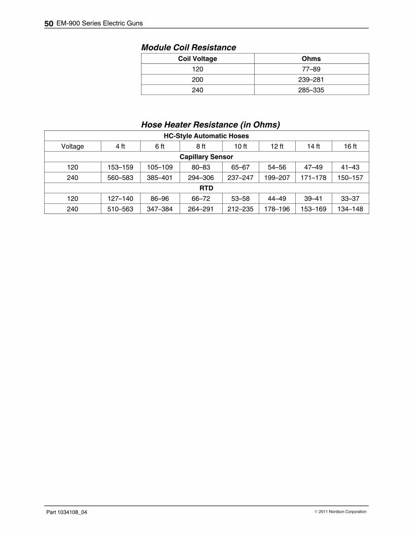
EM-900 Series Electric Guns50
Part 1034108_04 � 2011 Nordson Corporation
Module Coil Resistance
Coil Voltage Ohms
120 77–89
200 239–281
240 285–335
Hose Heater Resistance (in Ohms)
HC‐Style Automatic Hoses
Voltage 4 ft 6 ft 8 ft 10 ft 12 ft 14 ft 16 ft
Capillary Sensor
120 153–159 105–109 80–83 65–67 54–56 47–49 41–43
240 560–583 385–401 294–306 237–247 199–207 171–178 150–157
RTD
120 127–140 86–96 66–72 53–58 44–49 39–41 33–37
240 510–563 347–384 264–291 212–235 178–196 153–169 134–148

EM-900 Series Electric Guns 51
Part 1034108_04� 2011 Nordson Corporation
Hose Heater Resistance (in Ohms) (contd)
Handgun Hoses
Voltage 8 ft 12 ft 16 ft
L1 Hose, Capillary Sensor
120 80–83 54–56 41–42
240 293–305 199–207 150–156
L1 Hose, RTD
120 73–80 49–54 36–40
240 298–306 199–204 149
L4 Hose, Capillary Sensor
120 71–74 48–50 36–38
240 283–294 192–200 145–152
L4 Hose, RTD
120 75–79 45–52 37–39
240 298–315 199–209 149–157
SW4 Hose, RTD
120 75–79 49–52 37–39
240 298–314 199–209 149–157
Wiring Diagrams
4210061A
GREEN (GND)
YELLOW (COIL 1)
YELLOW (COIL 1)
BLACK (RTD)
BLACK (RTD)
BROWN (HTR)
BROWN (HTR)
11
22
33
44
55
66
77
88
99
1010
1111
1212
1313
1414
4
8
12 14
11
7
31
Count pins from left to right
Figure 32 Cordset Configuration for EM-900 14-Pin Connector

EM-900 Series Electric Guns52
Part 1034108_04 � 2011 Nordson Corporation
Wiring Diagrams (contd)
4210052A
GRN/YEL
BROWN (heater)
BROWN (heater)
BLACK (RTD)
BLACK (RTD)
YELLOW (Coil Set 1)
YELLOW (Coil Set 1)
HEATER
RTD
COIL 'A'
1
2
3
4
5
6
7
8
9
10
11
12
13
14
Figure 33 Wiring for EM-901
4210053A
1
2
3
4
5
6
7
8
9
10
11
12
13
14
GRN/YEL
BROWN (heater)
BROWN (heater)
BLACK (RTD)
BLACK (RTD)
YELLOW (Coil Set 1)
YELLOW (Coil Set 1)
HEATER
RTD
COIL 'A'
COIL 'B'
Figure 34 Wiring for EM-902

EM-900 Series Electric Guns 53
Part 1034108_04� 2011 Nordson Corporation
4210054A
1
2
3
4
5
6
7
8
9
10
11
12
13
14
GRN/YEL
BROWN (heater)
BROWN (heater)
BLACK (RTD)
BLACK (RTD)
YELLOW (Coil Set 1)
YELLOW (Coil Set 1)
HEATER
HEATER
RTD
COIL 'A'
COIL 'B'
COIL 'C'
Figure 35 Wiring for EM-903
4210055A
1
2
3
4
5
6
7
8
9
10
11
12
13
14
GRN/YEL
BROWN (heater)
BROWN (heater)
HEATER
HEATER
RTD
COIL 'A'
COIL 'B'
COIL 'C'
COIL 'D'
BLACK (RTD)
BLACK (RTD)
YELLOW (Coil Set 1)
YELLOW (Coil Set 1)
Figure 36 Wiring for EM-904
Dimensions

EM-900 Series Electric Guns54
Part 1034108_04 � 2011 Nordson Corporation

