emc celerra v5.0 windows clients product guide windows clients product guide p/n 300-006-488 ... the...
TRANSCRIPT
EMC CorporationCorporate Headquarters:
Hopkinton, MA 01748-9103
1-508-435-1000www.EMC.com
EMC® Celerra® MPFS over FC and iSCSIv5.0 Windows Clients
Product GuideP/N 300-006-488
REV A05
EMC Celerra MPFS over FC and iSCSI v5.0 Windows Clients Product Guide2
Copyright © 2007-2009 EMC Corporation. All rights reserved.
Published December 2009
EMC believes the information in this publication is accurate as of its publication date. The information is subject to change without notice.
THE INFORMATION IN THIS PUBLICATION IS PROVIDED “AS IS.” EMC CORPORATION MAKES NO REPRESENTATIONS OR WARRANTIES OF ANY KIND WITH RESPECT TO THE INFORMATION IN THIS PUBLICATION, AND SPECIFICALLY DISCLAIMS IMPLIED WARRANTIES OF MERCHANTABILITY OR FITNESS FOR A PARTICULAR PURPOSE.
Use, copying, and distribution of any EMC software described in this publication requires an applicable software license.
For the most up-to-date regulatory document for your product line, go to the Technical Documentation and Advisories section on EMC Powerlink.
For the most up-to-date listing of EMC product names, see EMC Corporation Trademarks on EMC.com.
All other trademarks used herein are the property of their respective owners.

EMC Celerra MPFS over FC and iSCSI v5.0 Windows Clients Product Guide 3
Preface
Chapter 1 Introducing EMC Celerra MPFS over FC and iSCSIOverview of EMC Celerra MPFS over FC and iSCSI .................. 18EMC Celerra MPFS architectures ................................................... 19
EMC Celerra MPFS over Fibre Channel................................. 19EMC Celerra MPFS over iSCSI ................................................ 21MPFS configuration summary................................................. 24
How EMC Celerra MPFS works..................................................... 28
Chapter 2 MPFS Environment ConfigurationConfiguration roadmap ................................................................... 30Implementation guidelines.............................................................. 32
Celerra with MPFS recommendations.................................... 32Storage configuration recommendations ............................... 34MPFS feature configurations.................................................... 35
MPFS installation and configuration process ............................... 37Configuration planning checklist............................................ 38
Verifying system components ......................................................... 40Required hardware components ............................................. 40Required software components ............................................... 43Verifying configuration............................................................. 43Verifying storage array requirements ..................................... 44Verifying the Fibre Channel switch requirements (FC configuration) ..................................................................... 45Verifying the IP-SAN switch requirements............................ 46Verifying the IP-SAN CLARiiON CX3 or CX4 requirements............................................................................... 47
Contents

EMC Celerra MPFS over FC and iSCSI v5.0 Windows Clients Product Guide4
Contents
Setting up the Celerra Network Server ......................................... 49Setting up the file system................................................................. 50
Before creating a file system .................................................... 50Creating a file system on a Celerra Network Server ............ 51
Enabling MPFS for the Celerra Network Server .......................... 57Configuring the CLARiiON using CLI commands ..................... 58
Best practices .............................................................................. 58Configuring the SAN and storage.................................................. 59
Installing the Fibre Channel switch (FC configuration) ...... 59Zoning the SAN switch (FC configuration)........................... 59Configuring the iSCSI-to-Fibre Channel bridge (iSCSI configuration)................................................................. 60Creating a security file on the Celerra Network Server....... 64CLARiiON iSCSI port configuration ...................................... 65Access Logix configuration...................................................... 66
Installing the MPFS software .......................................................... 68Before installing ......................................................................... 68Installing the MPFS software................................................... 69Operating MPFS through a firewall ....................................... 72
Configuring and accessing storage ................................................ 73Installing the Fibre Channel driver (FC configuration) ....... 73Installing and configuring the initiator (iSCSI configuration)................................................................. 76
Mapping an MPFS share to a network drive................................ 85
Chapter 3 Uninstalling or Upgrading MPFS SoftwareUninstalling the MPFS software..................................................... 92Upgrading the MPFS software ....................................................... 95
Attempting to install over existing MPFS software ............. 95Installing a later version of MPFS software........................... 96
Disabling an active MPFS software session.................................. 97
Chapter 4 MPFS Command Line InterfaceOverview of the command line interface.................................... 100mpfscopy.......................................................................................... 101mpfsctl -?.......................................................................................... 103mpfsctl config .................................................................................. 104mpfsctl disable ................................................................................ 105mpfsctl diskspeed ........................................................................... 106mpfsctl enable ................................................................................. 107mpfsctl inq ....................................................................................... 109

5EMC Celerra MPFS over FC and iSCSI v5.0 Windows Clients Product Guide
Contents
mpfsctl list ........................................................................................ 110mpfsctl reset ..................................................................................... 111mpfsctl stats ..................................................................................... 112mpfsctl version ................................................................................ 114mpfsinfo............................................................................................ 115mpfsinq............................................................................................. 116
Appendix A Error Messages and TroubleshootingMPFS messages sent to the event log........................................... 118Messages displayed in error message boxes ............................... 119Using Windows Event Viewer with MPFS.................................. 120
Log type: Warning ................................................................... 120Log type: Error ......................................................................... 120Log type: Information ............................................................. 120
Troubleshooting MPFS software ................................................... 125Confirming MPFS software installation ............................... 125Installing difficulties ................................................................ 126Uninstalling difficulties........................................................... 126
Appendix B Connecting CLARiiON CX3-40C iSCSI CablesiSCSI cabling .................................................................................... 128
Glossary
Index

EMC Celerra MPFS over FC and iSCSI v5.0 Windows Clients Product Guide6
Contents

EMC Celerra MPFS over FC and iSCSI v5.0 Windows Clients Product Guide 7
Title Page
1 Celerra unified storage with Fibre Channel ............................................... 202 Celerra gateway with Fibre Channel........................................................... 203 Celerra unified storage with iSCSI .............................................................. 214 Celerra unified storage with iSCSI (MDS-based) ...................................... 225 Celerra gateway with iSCSI .......................................................................... 226 Celerra gateway with iSCSI (MDS-based).................................................. 237 Configuration roadmap................................................................................. 318 Information window before Install.............................................................. 709 EMC MPFS Installer dialog box ................................................................... 7010 EMC MPFS is Installed dialog box .............................................................. 7111 Log On to Target dialog box......................................................................... 8112 Target Properties dialog box ........................................................................ 8213 Opening a Celerra Network Server to view possible shares .................. 8514 List of Available Shares ................................................................................. 8615 Selecting the MPFS Volume Properties....................................................... 8616 MPFS Properties window ............................................................................. 8717 Advanced Option Dialog window .............................................................. 8818 Global Options window................................................................................ 8919 Opening the Control Panel ........................................................................... 9220 Control Panel window................................................................................... 9321 Add or Remove Programs window............................................................. 9322 EMC MPFS Uninstall completed message window.................................. 9423 Previous installation detected window....................................................... 9524 EMC MPFS Installer window with Exit button active.............................. 9625 MPFS Properties window ............................................................................. 9726 Global Options window.............................................................................. 10427 Opening the Windows Event Viewer........................................................ 12128 Event Viewer window................................................................................. 12229 Selecting an Error message ......................................................................... 12230 Event Properties window............................................................................ 123
Figures
EMC Celerra MPFS over FC and iSCSI v5.0 Windows Clients Product Guide8
Figures
31 Up and down arrows on Event Properties window............................... 12432 Using mpfsctl version to verify MPFS software is installed.................. 12533 CLARiiON CX3-40C storage processor ports .......................................... 129

EMC Celerra MPFS over FC and iSCSI v5.0 Windows Clients Product Guide 9
Title Page
1 MPFS configuration summary ...................................................................... 242 Data Mover capacity guidelines.................................................................... 333 Prefetch and read cache requirements ......................................................... 344 MPFS executable files with Windows OS versions .................................... 695 Windows server firewall ports...................................................................... 726 Correct arraycommpath and failovermode settings .................................. 737 Windows command line interface commands ......................................... 1008 MPFS iSCSI error messages ........................................................................ 1189 MPFS FC error messages.............................................................................. 11810 Windows messages displayed in message boxes ..................................... 11911 CLARiiON SP iSCSI IP addresses............................................................... 128
Tables

EMC Celerra MPFS over FC and iSCSI v5.0 Windows Clients Product Guide10
Tables

EMC Celerra MPFS over FC and iSCSI v5.0 Windows Clients Product Guide 11
Preface
As part of an effort to improve and enhance the performance and capabilities of its product lines, EMC periodically releases versions of its hardware and software. Therefore, some functions described in this document may not be supported by all versions of the software or hardware currently in use. For the most up-to-date information on product features, refer to your product release notes.
If a product does not function properly or does not function as described in this document, contact your EMC representative.
Important Check the EMC Powerlink website, http://Powerlink.EMC.com, to ensure you have the latest versions of the MPFS software and documentation.
For software, open Support > Software Downloads and Licensing > Downloads C > Celerra MPFS Clients for Windows (Fibre Channel and iSCSI) and then select the necessary software for MPFS from the menu.
For documentation, open Support > Technical Documentation and Advisories > Software ~C~ Documentation > Celerra MPFS over Fibre Channel or Celerra MPFS over iSCSI.
Note: You must be a registered Powerlink user to download the MPFS software.
12 EMC Celerra MPFS over FC and iSCSI v5.0 Windows Clients Product Guide
Preface
Audience This document is part of the EMC Celerra MPFS documentation set, and is intended for use by Windows system administrators responsible for installing and maintaining EMC Celerra Windows servers.
Readers of this document are expected to be familiar with the following topics:
◆ EMC Symmetrix or CLARiiON storage system
◆ EMC Celerra Network Server
◆ CIFS protocol
◆ Operating environments to install the Windows server include:
• Windows 2000 Server (Fibre Channel only)
• Windows Server 2003
• Windows Server 2008
• Windows Server XP Professional (iSCSI only)
• Windows Vista
Note: In this document, Windows refers to Microsoft Windows 2000 Server (Fibre Channel only), Microsoft Windows Server 2003, Microsoft Windows Server 2008, Microsoft Windows XP Professional (iSCSI only), or Microsoft Windows Vista. Be sure to read the EMC Celerra MPFS for Windows Clients Release Notes for a complete listing of specific release information.
Relateddocumentation
Related documents include:
◆ EMC Celerra MPFS for Windows Clients Release Notes
◆ EMC Host Connectivity Guide for VMWare ESX Server
◆ EMC documentation for HBAs
CLARiiON storage system◆ Removing ATF or CDE Software before Installing other Failover
Software
◆ EMC Navisphere Manager Administrator’s Guide and online help
Symmetrix storage system◆ Symmetrix product manual
EMC Celerra MPFS over FC and iSCSI v5.0 Windows Clients Product Guide 13
Preface
Celerra Network Server◆ EMC Celerra Network Server Documentation CD
◆ Using MPFS on Celerra
All of these publications can be found on the EMC Powerlink website.
Powerlink The EMC Powerlink website provides the most up-to-date information on documentation, downloads, interoperability, product lifecycle, target revisions, and bug fixes. As a registered Powerlink user, you can subscribe to receive notifications when updates occur.
E-Lab InteroperabilityNavigator
The EMC E-Lab Interoperability Navigator tool provides access to EMC interoperability support matrices. After logging in to Powerlink, go to Support > Interoperability and Product Lifecycle Information > E-Lab Interoperability Navigator.
Conventions used inthis document
EMC uses the following conventions for special notices.
Note: A note presents information that is important, but not hazard-related.
CAUTION!A caution contains information essential to avoid data loss or damage to the system or equipment.
IMPORTANT!An important notice contains information essential to operation of the software.
WARNING
A warning contains information essential to avoid a hazard that can cause severe personal injury, death, or substantial property damage if you ignore the warning.
DANGER
A danger notice contains information essential to avoid a hazard that will cause severe personal injury, death, or substantial property damage if you ignore the message.
14 EMC Celerra MPFS over FC and iSCSI v5.0 Windows Clients Product Guide
Preface
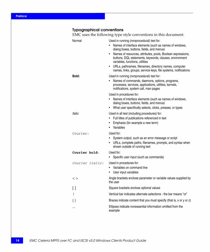
Typographical conventionsEMC uses the following type style conventions in this document:
Normal Used in running (nonprocedural) text for:• Names of interface elements (such as names of windows,
dialog boxes, buttons, fields, and menus)• Names of resources, attributes, pools, Boolean expressions,
buttons, DQL statements, keywords, clauses, environment variables, functions, utilities
• URLs, pathnames, filenames, directory names, computer names, links, groups, service keys, file systems, notifications
Bold: Used in running (nonprocedural) text for:• Names of commands, daemons, options, programs,
processes, services, applications, utilities, kernels, notifications, system call, man pages
Used in procedures for:• Names of interface elements (such as names of windows,
dialog boxes, buttons, fields, and menus)• What user specifically selects, clicks, presses, or types
Italic: Used in all text (including procedures) for:• Full titles of publications referenced in text• Emphasis (for example a new term)• Variables
Courier: Used for:• System output, such as an error message or script • URLs, complete paths, filenames, prompts, and syntax when
shown outside of running text
Courier bold: Used for:• Specific user input (such as commands)
Courier italic: Used in procedures for:• Variables on command line• User input variables
< > Angle brackets enclose parameter or variable values supplied by the user
[ ] Square brackets enclose optional values
| Vertical bar indicates alternate selections - the bar means “or”
{ } Braces indicate content that you must specify (that is, x or y or z)
... Ellipses indicate nonessential information omitted from the example
EMC Celerra MPFS over FC and iSCSI v5.0 Windows Clients Product Guide 15
Preface
Where to get help EMC support, product, and licensing information can be obtained as follows.
Product information — For documentation, release notes, software updates, or for information about EMC products, licensing, and service, go to the EMC Powerlink website (registration required) at:
http://Powerlink.EMC.com
Technical support — For technical support, go to EMC Customer Service on Powerlink. To open a service request through Powerlink, you must have a valid support agreement. Contact your EMC Customer Support Representative for details about obtaining a valid support agreement or to answer any questions about your account.
Your comments Your suggestions will help us continue to improve the accuracy, organization, and overall quality of the user publications. Send your opinion of this document to:
16 EMC Celerra MPFS over FC and iSCSI v5.0 Windows Clients Product Guide
Preface

Introducing EMC Celerra MPFS over FC and iSCSI 17
1Invisible Body Tag
This chapter provides an overview of EMC Celerra MPFS over FC and iSCSI and its architecture. The chapter includes the following topics:
◆ Overview of EMC Celerra MPFS over FC and iSCSI ................... 18◆ EMC Celerra MPFS architectures .................................................... 19◆ How EMC Celerra MPFS works ...................................................... 28
Introducing EMCCelerra MPFS over FC
and iSCSI
18 EMC Celerra MPFS over FC and iSCSI v5.0 Windows Clients Product Guide
Introducing EMC Celerra MPFS over FC and iSCSI
Overview of EMC Celerra MPFS over FC and iSCSI EMC® Celerra® Multi-Path File System (MPFS) over Fibre Channel (FC) lets Linux, Windows, UNIX, AIX, or Solaris servers access shared data concurrently over FC connections, whereas EMC Celerra MPFS over Internet Small Computer System Interface (iSCSI) lets servers access shared data concurrently over an iSCSI connection.
EMC Celerra MPFS uses common IP LAN topology to transport data and metadata for the EMC Celerra MPFS.
Without the MPFS file system, servers can access shared data using standard Network File System (NFS) or Common Internet File System (CIFS) protocols; the MPFS file system accelerates data access by providing separate transports for file data (file content) and metadata (control data).
For an FC-enabled server, data is transferred directly between the Windows server and storage array over a Fibre Channel SAN.
For an iSCSI-enabled server, data is transferred over the IP LAN between the Windows server and storage array for a unified storage or gateway configuration or through an iSCSi-to-Fibre Channel bridge for a unified storage (MDS-based) or gateway (MDS-based) configuration.
Metadata passes through the Celerra Network Server (and the IP network), which includes the NAS portion of the configuration.

EMC Celerra MPFS architectures 19
Introducing EMC Celerra MPFS over FC and iSCSI
EMC Celerra MPFS architecturesThere are two basic EMC Celerra MPFS architectures:
◆ EMC Celerra MPFS over Fibre Channel
◆ EMC Celerra MPFS over iSCSI
The FC architecture consists of two configurations:• Celerra unified storage with Fibre Channel (NS20FC, NS-120,
NS40FC, NS-480, or NS-960)
• Celerra gateway with Fibre Channel (NS40G, NS80G, NS-G2, NS-G8, or NSX with EMC CLARiiON® or EMC Symmetrix®)
The iSCSI architecture consists of four configurations:• Celerra unified storage with iSCSI (NS-120, NS40 for MPFS,
NS-480, or NS-960)
• Celerra unified storage with iSCSI (MDS-based) (NS20FC, NS-120, NS40FC, NS-480, or NS-960)
• Celerra gateway with iSCSI (NS40G, NS80G, NS-G2, NS-G8, or NSX with CLARiiON or Symmetrix)
• Celerra gateway with iSCSI (MDS-based) (NS40G, NS80G, NS-G2, NS-G8, or NSX with CLARiiON or Symmetrix)
Each is briefly described in this section.
EMC Celerra MPFS over Fibre Channel
The EMC Celerra MPFS over Fibre Channel architecture consists of the following:
◆ Celerra Network Server with MPFS — A network-attached storage device that is configured with an EMC Celerra Network Server with MPFS software
◆ Symmetrix or CLARiiON storage array◆ Windows server with MPFS software connected to a Celerra
Network Server through the IP LAN, Symmetrix, or CLARiiON storage arrays using Fibre Channel architecture
The following figures show the common Fibre Channel configurations. Figure 1 on page 20 shows the Celerra unified storage with Fibre Channel configuration where the Windows servers are connected to an NS20FC, NS-120, NS40FC, NS-480, or NS-960 using an IP switch and one or more FC switches. In a smaller configuration of one or two servers, the servers can be connected directly to the NS20FC or NS-120 without the use of Fibre Channel switches.

20 EMC Celerra MPFS over FC and iSCSI v5.0 Windows Clients Product Guide
Introducing EMC Celerra MPFS over FC and iSCSI
Figure 1 Celerra unified storage with Fibre Channel
Figure 2 on page 20 shows the Celerra gateway with Fibre Channel configuration. In this diagram, the Windows servers are connected to a CLARiiON or a Symmetrix storage array using an NS40G, NS80G, NS-G2, NS-G8, or NSX and IP switch or optional Fibre Channel switch.
Figure 2 Celerra gateway with Fibre Channel
IP switch
FC switch
FC
NFS/CIFS
NS20FC, NS-120, NS40FC,NS-480, or NS-960
MPFS data
Servers
CNS-001629
MPFS metadata
IP switch
NS40G, NS80G, NS-G2,NS-G8, or NSX
FC switch
FC
FC
NFS/CIFS
CLARiiON or Symmetrix
MPFS data
Servers
CNS-001097
MPFSmetadata
EMC Celerra MPFS architectures 21
Introducing EMC Celerra MPFS over FC and iSCSI
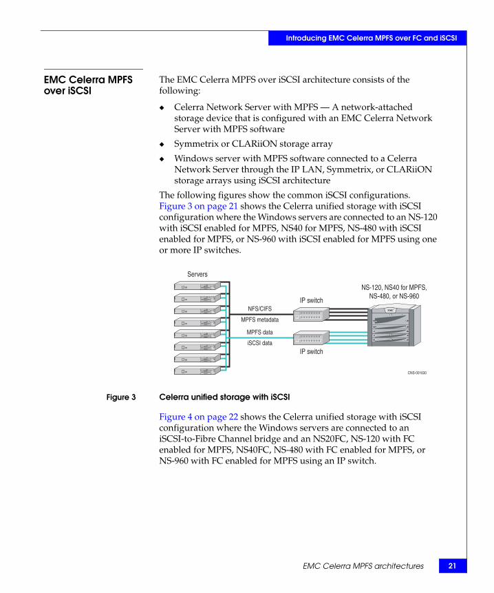
EMC Celerra MPFS over iSCSI
The EMC Celerra MPFS over iSCSI architecture consists of the following:
◆ Celerra Network Server with MPFS — A network-attached storage device that is configured with an EMC Celerra Network Server with MPFS software
◆ Symmetrix or CLARiiON storage array
◆ Windows server with MPFS software connected to a Celerra Network Server through the IP LAN, Symmetrix, or CLARiiON storage arrays using iSCSI architecture
The following figures show the common iSCSI configurations. Figure 3 on page 21 shows the Celerra unified storage with iSCSI configuration where the Windows servers are connected to an NS-120 with iSCSI enabled for MPFS, NS40 for MPFS, NS-480 with iSCSI enabled for MPFS, or NS-960 with iSCSI enabled for MPFS using one or more IP switches.
Figure 3 Celerra unified storage with iSCSI
Figure 4 on page 22 shows the Celerra unified storage with iSCSI configuration where the Windows servers are connected to an iSCSI-to-Fibre Channel bridge and an NS20FC, NS-120 with FC enabled for MPFS, NS40FC, NS-480 with FC enabled for MPFS, or NS-960 with FC enabled for MPFS using an IP switch.
IP switchNFS/CIFS
NS-120, NS40 for MPFS,NS-480, or NS-960
MPFS data
Servers
IP switch
CNS-001630
MPFS metadata
iSCSI data

22 EMC Celerra MPFS over FC and iSCSI v5.0 Windows Clients Product Guide
Introducing EMC Celerra MPFS over FC and iSCSI
Figure 4 Celerra unified storage with iSCSI (MDS-based)
Figure 5 on page 22 shows the Celerra gateway with iSCSI configuration where the Windows servers are connected to a CLARiiON or a Symmetrix storage array with an NS40G, NS80G, NS-G2, NS-G8, or NSX using one or more IP switches.
Figure 5 Celerra gateway with iSCSI
IP switchNFS/CIFS
NS20FC, NS-120, NS40FC,NS-480, or NS-960
MPFS data
Servers
CNS-001631
MPFS metadata
iSCSI data
iSCSI-to-FC bridgeFC
IP switch
NS40G, NS80G, NS-G2,NS-G8, or NSX
IP switch
FCNFS/CIFS
CLARiiON or Symmetrix
MPFS data
iSCSI data
Servers
CNS-001098
MPFSmetadata

EMC Celerra MPFS architectures 23
Introducing EMC Celerra MPFS over FC and iSCSI
Figure 6 on page 23 shows the Celerra gateway with iSCSI configuration where the Windows servers are connected to a CLARiiON or Symmetrix storage array with an iSCSI-to-Fibre Channel bridge and an NS40G, NS80G, NS-G2, NS-G8, or NSX using an IP switch.
Figure 6 Celerra gateway with iSCSI (MDS-based)
IP switch
NS40G, NS80G, NS-G2,NS-G8, or NSX
FC
FC
NFS/CIFS
CLARiiON or Symmetrix
MPFS data
MPFSmetadata
Servers
CNS-001108
iSCSI data
iSCSI-to-FC bridge

24 EMC Celerra MPFS over FC and iSCSI v5.0 Windows Clients Product Guide
Introducing EMC Celerra MPFS over FC and iSCSI
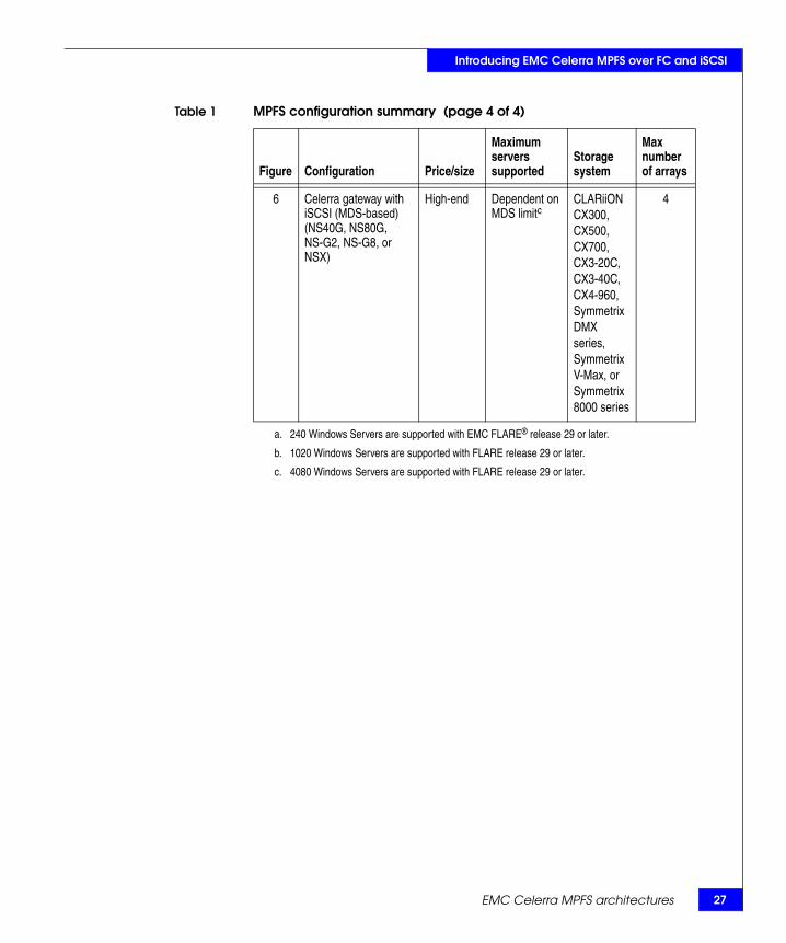
MPFS configuration summary
Table 1 on page 24 compares the MPFS configurations.
Table 1 MPFS configuration summary (page 1 of 4)
Figure Configuration Price/size
Maximum servers supported
Storage system
Max number of arrays
1 Celerra unified storage with Fibre Channel (NS20FC)
Entry-level 60 CLARiiON CX3-10F
1
Celerra unified storage with Fibre Channel (NS-120)
Entry-level 120a CLARiiON CX4-120
Celerra unified storage with Fibre Channel (NS40FC)
Midtier 120 CLARiiON CX3-40F
Celerra unified storage with Fibre Channel (NS-480)
Midtier 240b CLARiiON CX4-480
Celerra unified storage with Fibre Channel (NS-960)
High-end 500c CLARiiON CX4-960
2 Celerra gateway with Fibre Channel (NS40G, NS80G, NS-G2, NS-G8, or NSX)
High-end Dependent on CLARiiON and Symmetrix limitsa, b, c
CLARiiON CX300,CX500,CX700,CX3-20F, CX3-40F, CX4-120, CX4-240, CX4-480, CX4-960, Symmetrix DMX™ series, Symmetrix V-Max™ series, or Symmetrix 8000 series
4

EMC Celerra MPFS architectures 25
Introducing EMC Celerra MPFS over FC and iSCSI
3 Celerra unified storage with iSCSI (NS-120 with iSCSI enabled for MPFS)
Entry-level 120a CLARiiON CX4-120
1
Celerra unified storage with iSCSI (NS40 for MPFS)
Entry-level 120 CLARiiON CX4-120
Celerra unified storage with iSCSI (NS-480 with iSCSI enabled for MPFS)
Midtier 240b CLARiiON CX4-480
Celerra unified storage with iSCSI (NS-960 with iSCSI enabled for MPFS)
High-end 500c CLARiiON CX4-960
4 Celerra unified storage with iSCSI (MDS-based) (NS20FC)
Entry-level Dependent on MDS limita
CLARiiON CX4-120
1
Celerra unified storage with iSCSI (MDS-based) (NS-120 with FC enabled for MPFS)
Entry-level Dependent on MDS limita
CLARiiON CX4-120
Celerra unified storage with iSCSI (MDS-based) (NS40FC)
Midtier Dependent on MDS limit
CLARiiON CX3-40C
Celerra unified storage with iSCSI (MDS-based) (NS-480 with FC enabled for MPFS)
Midtier Dependent on MDS limitb
CLARiiON CX4-480
Celerra unified storage with iSCSI (MDS-based) (NS-960 with FC enabled for MPFS)
High-end Dependent on MDS limitc
CLARiiON CX4-960
Table 1 MPFS configuration summary (page 2 of 4)
Figure Configuration Price/size
Maximum servers supported
Storage system
Max number of arrays

26 EMC Celerra MPFS over FC and iSCSI v5.0 Windows Clients Product Guide
Introducing EMC Celerra MPFS over FC and iSCSI
5 Celerra gateway with iSCSI (NS40G, NS80G, NS-G2, NS-G8, or NSX)
Midtier Dependent on CLARiiON limitsa,b,c
CLARiiONCX300,CX500,CX700,CX3-20C, CX3-40C, CX4-120, CX4-240, CX4-480, or CX4-960
4
Celerra gateway with iSCSI (NS40G, NS80G, NS-G2, NS-G8, or NSX)
High-end Dependent on CLARiiON limitsa,b,c
CLARiiONCX300,CX500,CX700,CX3-20C, CX3-40C, CX4-120, CX4-240, CX4-480, CX4-960,Symmetrix DMX series, Symmetrix V-Max, or Symmetrix 8000 series
Table 1 MPFS configuration summary (page 3 of 4)
Figure Configuration Price/size
Maximum servers supported
Storage system
Max number of arrays
EMC Celerra MPFS architectures 27
Introducing EMC Celerra MPFS over FC and iSCSI
6 Celerra gateway with iSCSI (MDS-based) (NS40G, NS80G, NS-G2, NS-G8, or NSX)
High-end Dependent on MDS limitc
CLARiiONCX300,CX500,CX700,CX3-20C, CX3-40C, CX4-960, Symmetrix DMX series, Symmetrix V-Max, or Symmetrix 8000 series
4
a. 240 Windows Servers are supported with EMC FLARE® release 29 or later.
b. 1020 Windows Servers are supported with FLARE release 29 or later.
c. 4080 Windows Servers are supported with FLARE release 29 or later.
Table 1 MPFS configuration summary (page 4 of 4)
Figure Configuration Price/size
Maximum servers supported
Storage system
Max number of arrays

28 EMC Celerra MPFS over FC and iSCSI v5.0 Windows Clients Product Guide
Introducing EMC Celerra MPFS over FC and iSCSI
How EMC Celerra MPFS worksAlthough called a file system, the EMC Celerra MPFS is neither a new nor a modified format for storing files. Instead, the MPFS file system interoperates and uses the standard NFS and CIFS protocols to enforce access permissions. The MPFS file system uses a protocol called File Mapping Protocol (FMP) to exchange metadata between the Windows server and the Celerra Network Server.
All requests unrelated to file I/O pass directly to the NFS/CIFS layer. The MPFS layer intercepts only the open, close, read, and write system calls.
When a Windows server intercepts a file-read call, it sends a request to the Celerra Network Server asking for the file's location. The Celerra Network Server responds with a list of file extents, which the Windows server then uses to read the file data directly from the disk.
When a Windows server intercepts a file-write call, it asks the Celerra Network Server to allocate blocks on disk for the file. The Celerra Network Server allocates the space in contiguous extents and sends the extent list to the Windows server. The Windows server then writes data directly to disk, informing the Celerra Network Server when finished, so that the Celerra Network Server can permit other Windows servers to access the file.
The remaining chapters describe how to install, manage, and tune EMC Celerra Windows servers. The Using MPFS on Celerra technical module, located on the EMC Celerra Network Server Documentation CD and also available on Powerlink® at http://Powerlink.EMC.com, provides information on the Celerra Network Server MPFS commands.

MPFS Environment Configuration 29
2Invisible Body Tag
This chapter presents a high-level overview of configuring and installing the EMC Celerra MPFS.
Topics include:
◆ Configuration roadmap .................................................................... 30◆ Implementation guidelines............................................................... 32◆ MPFS installation and configuration process ................................ 37◆ Verifying system components .......................................................... 40◆ Setting up the Celerra Network Server........................................... 49◆ Setting up the file system.................................................................. 50◆ Enabling MPFS for the Celerra Network Server ........................... 57◆ Configuring the CLARiiON using CLI commands ...................... 58◆ Configuring the SAN and storage ................................................... 59◆ Installing the MPFS software ........................................................... 68◆ Configuring and accessing storage ................................................. 73◆ Mapping an MPFS share to a network drive ................................. 85
MPFS EnvironmentConfiguration

30 EMC Celerra MPFS over FC and iSCSI v5.0 Windows Clients Product Guide
MPFS Environment Configuration
Configuration roadmapFigure 7 on page 31 shows the roadmap for configuring and installing the EMC Celerra MPFS over FC and iSCSI architecture for both FC and iSCSI environments. The roadmap contains the topics representing sequential phases of the configuration and installation process. The descriptions of each phase, which follow, contain an overview of the tasks required to complete the process, and a list of related documents for more information.

Configuration roadmap 31
MPFS Environment Configuration
Figure 7 Configuration roadmap
!
MPFS installation and configuration process
Verifying system components
Setting up the file system
Installing the MPFS software
Implementation guidelines
Enabling MPFS for the Celerra Network Server
Setting up the Celerra Network Server
Configuring the SAN and storage
Configuring and accessing storage
Configuring the CLARiiON using CLI commands
Mapping an MPFS share to a network drive

32 EMC Celerra MPFS over FC and iSCSI v5.0 Windows Clients Product Guide
MPFS Environment Configuration
Implementation guidelinesThe following MPFS implementation guidelines are valid for all MPFS installations.
Celerra with MPFS recommendations
The following recommendations are described in detail in the EMC Celerra MPFS over iSCSI Applied Best Practices Guide and the Celerra Network Server Best Practices for Performance, which can be found at http://Powerlink.EMC.com:
◆ MPFS is optimized for large I/O transfers and may be useful for workloads with average I/O sizes as small as 16 KB. However, MPFS has been shown conclusively to improve performance for I/O sizes of 128 KB and greater.
◆ For best MPFS performance, in most cases, configure the Celerra volumes using a volume stripe size of 256 KB.
◆ EMC PowerPath® is supported, but is not recommended. Path failover is built into the Windows server. When using PowerPath, the performance of the MPFS system is expected to be lower. Knowledgebase article emc 165953 contains details on using PowerPath and MPFS.
◆ When MPFS is started, 16 threads are run, which is the default number of MPFS threads. The maximum number of threads is 128. If system performance is slow, gradually increase the number of threads allotted for the Data Mover to improve system performance. Add threads conservatively, as the Data Mover allocates 16 KB of memory to accommodate each new thread. The optimal number of threads depends on the network configuration, the number of Windows servers, and the workload.
Using MPFS on Celerra provides the procedures necessary to adjust the thread count and can be found on the EMC Celerra Network Server Documentation CD.

Implementation guidelines 33
MPFS Environment Configuration
128 TB Data Movercapacity
MPFS supports 128 TB total capacity per Data Mover. This larger Data Mover capacity allows a single 128 TB data access point through the Nested Mount File System (NMFS). Table 2 on page 33 lists the conditions and restrictions of the 128 TB Data Mover capacity.
Additional guidelines are listed below:
◆ EMC Celerra Replicator™ and Celerra SnapSure are not supported with the 128 TB Data Mover capacity. Existing snaps and replication sessions must be deleted when using MPFS with 128 TB Data Mover capacity. If you plan to use Celerra Replicator or Celerra SnapSure, the Data Mover capacity will be the same as the non-MPFS capacity limits.
◆ The 128 TB Data Mover capacity is only supported with MPFS running in an NS-960 or NSX environment.
◆ The Celerra Network Server must be configured for MPFS. However, CIFS, MPFS, and NFS servers can all connect to share file systems.
◆ Single file system size is limited to 16 TB.
◆ Performance is no different during data transfer or Data Mover bootup time when using 128 TB Data Movers from any other Data Mover capacity.
The EMC E-Lab™ Interoperability Navigator contains the latest Data Mover capacity information and MPFS-related restrictions.
Table 2 Data Mover capacity guidelines
MPFS with FC or ATA Conditions and restrictions NS-960 or NSX
Limit per Data Mover/Blade
Minimum NAS version required
5.5.31.x
Data Mover capacity 128 TB
Existing snaps and replication sessions
Must be deleted
New EMC SnapSure™ or replication sessions
Not supported

34 EMC Celerra MPFS over FC and iSCSI v5.0 Windows Clients Product Guide
MPFS Environment Configuration
Windows serverconfiguration
All Windows servers using the MPFS software require:
◆ At least one Fibre Channel connection or an iSCSI initiator connected to a SAN switch, or directly to a CLARiiON or Symmetrix storage array
◆ Network connections to the Data Mover
Note: When deploying MPFS over iSCSI on an NS-120, NS40 for MPFS, NS-480, or NS-960 unified storage configuration or a gateway configuration based on the iSCSI-enabled CLARiiON CX3 or CX4 series storage arrays, the CLARiiON iSCSI target is used. In all other MPFS over Celerra gateway with iSCSI implementations, the iSCSI target on the iSCSI-to-Fibre Channel bridge is used.
Storage configuration recommendations
Windows servers read and write directly from a storage system. This has several implications:
◆ FLARE release 26 or later should be used for best performance in new MPFS configurations. The EMC CLARiiON Best Practices for Fibre Channel Storage: FLARE Release 26 Firmware Update provides more details.
◆ All mounted MPFS file systems should be unmounted from the Windows server before changing any storage device or switch configuration.
Table 3 on page 34 lists the prefetch and read cache requirements.
Table 3 Prefetch and read cache requirements
Prefetch requirements Read cache Notes
Modest 50–100 MB 80% of the systems fall under this category.
Heavy 250 MB Requests greater than 64 KB and sequential reads from many LUNs expected over 300 MB/s.
Extremely heavy 1 GB 120 or more drives reading in parallel.

Implementation guidelines 35
MPFS Environment Configuration
MPFS feature configurations
The following sections describe the configurations for MPFS features.
iSCSI CHAPauthentication
The Windows server with MPFS software and the CLARiiON storage array support the Challenge Handshake Authentication Protocol (CHAP) for iSCSI network security.
CHAP provides a method for the Windows server and CLARiiON storage array to authenticate each other through an exchange of a shared secret (a security key that is similar to a password), which is typically a string of 12 to 16 bytes.
CAUTION!If CHAP security is not configured for the CLARiiON storage array, any computer connected to the same IP network as the CLARiiON storage array iSCSI ports can read from or write to the CLARiiON storage array.
CHAP has two variants — one-way and reverse CHAP authentication:
◆ In one-way CHAP authentication, CHAP sets up the accounts that the Windows server uses to connect to CLARiiON storage array. The CLARiiON storage array authenticates the Windows server.
◆ In reverse CHAP authentication, the CLARiiON storage array authenticates the Windows server and the Windows server also authenticates the CLARiiON storage array.
Because CHAP secrets are shared between the Windows server and CLARiiON storage array, the CHAP secrets must be configured the same on both the Windows server and CLARiiON storage array.
The CX-Series iSCSI Security Setup Guide contains detailed information regarding CHAP and can be found on the Powerlink website.
36 EMC Celerra MPFS over FC and iSCSI v5.0 Windows Clients Product Guide
MPFS Environment Configuration
VMware ESX(optional)
VMware is a software suite for optimizing and managing IT environments through virtualization technology. MPFS supports the Windows Server guest operating systems running on a VMware ESX Server.
The VMware ESX Server is a robust, production-proven virtualization layer that abstracts processor, memory, storage, and networking resources into multiple virtual machines (software representation of a physical machine) running side-by-side on the same server.
VMware is not tied to any operating system, giving customers a bias-free choice of operating systems and software applications. All operating systems supported by VMware are supported with both Celerra iSCSI and NFS protocols for basic connectivity. This allows several instances of similar and different guest operating systems to run as virtual machines on one physical machine.
To run a Windows Server guest operating system on a VMware ESX Server, the configuration must meet the following requirements:
◆ Run a supported version of the Windows operating system.
◆ Have the CLARiiON supported HBA hardware and driver installed.
◆ Be connected to each SP in each storage system directly or through a switch. Each SP must have an IP connection.
◆ Be on a TCP/IP network connected to both SPs in the storage system.
Currently the VMware ESX Server has the following limitations:
◆ Booting the guest Windows server off iSCSI is not supported.
◆ PowerPath is not supported.
◆ Virtual machines that run the Windows Server guest operating system must use iSCSI to access the CLARiiON storage arrays.
◆ The virtual machine can be stored on a VMware datastore (CLARiiON or Symmetrix storage array) and accessed by the VMware ESX Server using either Fibre Channel (ESX Server versions 3.0.1, 3.0.2, or 3.5.1) or iSCSI (ESX Server version 3.5.1).
The EMC Host Connectivity Guide for VMWare ESX Server contains information on how to configure iSCSI initiator ports and how VMware operates in a Windows environment. The VMware website at http://www.vmware.com also provides more information.

MPFS installation and configuration process 37
MPFS Environment Configuration
MPFS installation and configuration processThe MPFS configuration process involves performing tasks on various system components in a specific order.
Note: This document contains guidelines for installing and configuring MPFS with several options. Disregard steps that do not pertain to your environment.
To manually install and configure MPFS:
1. Collect installation and configuration planning information and complete the checklist:
a. Collect the IP network addresses, Fibre Channel port addresses, iSCSI-to-Fibre Channel bridge information, and CLARiiON storage array information.
b. Map the Ethernet and TCP/IP network topology.
c. Map the Fibre Channel zoning topology.
d. Map the virtual storage area network (VSAN) topology.
2. Install the MPFS software manually (on a native or VMware1 hosted Windows operating system):
a. Install the HBA driver (for FC configuration).
b. Install and configure the iSCSI (for iSCSI configuration).2
c. Start the iSCSI service (for iSCSI configuration).
d. Install the MPFS software.
e. Check the MPFS software configuration.
1. “VMware ESX (optional)” on page 36 provides information.2. Installing Celerra iSCSI Host Components provides details.

38 EMC Celerra MPFS over FC and iSCSI v5.0 Windows Clients Product Guide
MPFS Environment Configuration
Configuration planning checklist
Collect the following information before beginning the MPFS installation and configuration process.
Note: The use of dynamic host configuration protocol (DHCP) to obtain IP addresses is not supported. Static IP addresses must be used.
For an FC and iSCSI configuration:
❑ SP A IP address .....................................................................................
❑ SP A login name....................................................................................
❑ SP A password.......................................................................................
❑ SP B IP address ......................................................................................
❑ SP B login name.....................................................................................
❑ SP B password .......................................................................................
❑ Zoning for Data Movers.......................................................................
❑ First Data Mover LAN blade IP address or Data Mover IP address ...............................................................................................
❑ Second Data Mover LAN blade IP address or Data Mover IP address ...............................................................................................
❑ Control Station IP address or CS address..........................................
❑ LAN IP address (same as LAN Data Movers) ..................................❑ Windows server IP address on LAN..................................................
❑ VSAN name ...........................................................................................
❑ VSAN number (make sure it is not in use) .......................................
For an FC configuration:
❑ SP A FC port assignment or FC ports ................................................
❑ SP B FC port assignment or FC ports.................................................❑ FC switch name .....................................................................................
❑ FC switch password .............................................................................
❑ FC switch port IP address....................................................................❑ Zoning for each FC HBA port .............................................................❑ Zoning for each FC director ................................................................
MPFS installation and configuration process 39
MPFS Environment Configuration
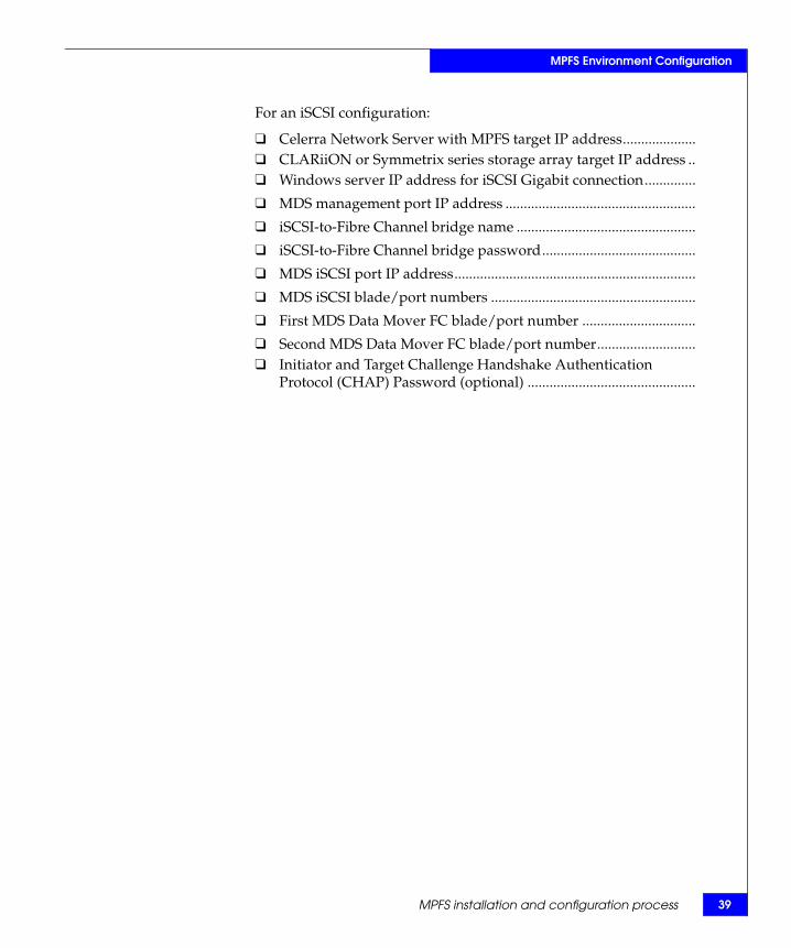
For an iSCSI configuration:
❑ Celerra Network Server with MPFS target IP address....................❑ CLARiiON or Symmetrix series storage array target IP address ..❑ Windows server IP address for iSCSI Gigabit connection..............
❑ MDS management port IP address ....................................................
❑ iSCSI-to-Fibre Channel bridge name .................................................
❑ iSCSI-to-Fibre Channel bridge password..........................................
❑ MDS iSCSI port IP address..................................................................
❑ MDS iSCSI blade/port numbers ........................................................
❑ First MDS Data Mover FC blade/port number ...............................
❑ Second MDS Data Mover FC blade/port number...........................❑ Initiator and Target Challenge Handshake Authentication
Protocol (CHAP) Password (optional) ..............................................

40 EMC Celerra MPFS over FC and iSCSI v5.0 Windows Clients Product Guide
MPFS Environment Configuration
Verifying system componentsMPFS environments require standard EMC Celerra hardware and software, with the addition of a few components that are specific to either FC or iSCSI configurations. This involves setting up an MPFS environment to verify that each of the previously mentioned components is in place and functioning normally. Each hardware and software component is discussed in the following sections.
Required hardware components
This section lists the MPFS configurations with the required hardware components.
MPFS Celerra unifiedstorage with Fibre
Channel configuration
The hardware components for an MPFS Celerra unified storage with Fibre Channel configuration are:
◆ A Celerra Network Server connected to an FC network and SAN
◆ An IP switch connected to the Celerra Network Server and the servers for data and metadata
◆ An FC switch with an HBA for each Windows server
“EMC Celerra MPFS over Fibre Channel” on page 19 contains more information.
MPFS Celerragateway with Fibre
Channel configuration
The hardware components for an MPFS Celerra gateway with Fibre Channel configuration are:
◆ A Celerra Network Server connected to an FC network and SAN◆ A fabric-connected storage system, either CLARiiON or
Symmetrix, with available LUNs◆ An IP switch connected to the Celerra Network Server and the
servers for data and metadata
◆ An FC switch with an HBA for each Windows server
“EMC Celerra MPFS over Fibre Channel” on page 19 contains more information.
Verifying system components 41
MPFS Environment Configuration
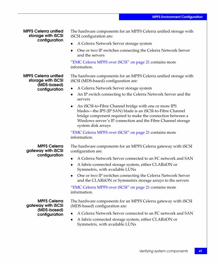
MPFS Celerra unifiedstorage with iSCSI
configuration
The hardware components for an MPFS Celerra unified storage with iSCSI configuration are:
◆ A Celerra Network Server storage system
◆ One or two IP switches connecting the Celerra Network Server and the servers
“EMC Celerra MPFS over iSCSI” on page 21 contains more information.
MPFS Celerra unifiedstorage with iSCSI
(MDS-based)configuration
The hardware components for an MPFS Celerra unified storage with iSCSI (MDS-based) configuration are:
◆ A Celerra Network Server storage system◆ An IP switch connecting to the Celerra Network Server and the
servers
◆ An iSCSI-to-Fibre Channel bridge with one or more IPS blades—the IPS (IP SAN) blade is an iSCSI-to-Fibre Channel bridge component required to make the connection between a Windows server’s IP connection and the Fibre Channel storage system disk arrays
“EMC Celerra MPFS over iSCSI” on page 21 contains more information.
MPFS Celerragateway with iSCSI
configuration
The hardware components for an MPFS Celerra gateway with iSCSI configuration are:
◆ A Celerra Network Server connected to an FC network and SAN◆ A fabric-connected storage system, either CLARiiON or
Symmetrix, with available LUNs◆ One or two IP switches connecting the Celerra Network Server
and the CLARiiON or Symmetrix storage arrays to the servers
“EMC Celerra MPFS over iSCSI” on page 21 contains more information.
MPFS Celerragateway with iSCSI
(MDS-based)configuration
The hardware components for an MPFS Celerra gateway with iSCSI (MDS-based) configuration are:
◆ A Celerra Network Server connected to an FC network and SAN◆ A fabric-connected storage system, either CLARiiON or
Symmetrix, with available LUNs

42 EMC Celerra MPFS over FC and iSCSI v5.0 Windows Clients Product Guide
MPFS Environment Configuration
◆ One or two IP switches connecting the Celerra Network Server to the servers
◆ An iSCSI-to-Fibre Channel bridge with one or more IPS blades—the IP SAN (IPS) blade is an iSCSI-to-Fibre Channel bridge component required to make the connection between a Windows server’s IP connection and the Fibre Channel storage system disk arrays
“EMC Celerra MPFS over iSCSI” on page 21 contains more information.
Note: A minimal working configuration should have at least one Gigabit Ethernet port per server. However, Fast Ethernet (100BaseT) is also supported. Using Fast Ethernet will limit the total throughput of the Windows server to a 12 MB/s theoretical limit.
A Windows server with MPFS software is required for all types of configurations.
Configuring GigabitEthernet ports
Two Gigabit Ethernet NICs, or a multiport NIC with two available ports, connected to isolated IP networks or subnets are recommended for each Windows server for iSCSI. For each Windows server for Fibre Channel, one NIC is required for CIFS and FMP traffic. For maximum performance, use:
◆ One port for the connection between the Windows server and the Data Mover for MPFS metadata transfer and CIFS traffic
Note: CIFS and FMP traffic must be on the same NIC port. This NIC must be first in the binding order as well.
◆ One port for the connection between the Windows server and the same subnet as the iSCSI discovery address dedicated to data transfer
Note: The second NIC for iSCSI must be on the same subnet as the discovery address.
Configuring and Managing EMC Celerra Networking provides detailed information for setting up network connections and is available on the Powerlink website.

Verifying system components 43
MPFS Environment Configuration
Required software components
The following software components are required for an MPFS configuration:
Note: The EMC Celerra MPFS for Windows Clients Release Notes provide a complete list of EMC supported operating system versions.
◆ Celerra Network Server NAS software version that supports either FC or iSCSI on Windows platforms
◆ Windows operating system version that supports HBAs or an iSCSI initiator
Note: The EMC E-Lab Interoperability Matrix lists the latest versions of Windows operating systems.
◆ MPFS software version 5.0 or later
◆ Windows iSCSI Initiator 2.03 or later
◆ Java Runtime Environment 1.5.0.11 or later to run the console applications
Verifying configuration
The next step in setting up MPFS is to verify whether each of the previously mentioned components is in place and functioning normally. If each of these components is operational, the “MPFS installation and configuration process” on page 37 provides more information.
Configure CIFS and start the services on the Celerra Network Server that will be used for MPFS connectivity.
Relateddocumentation
The following documents, available on the Powerlink website, provide additional information:◆ Configuring and Managing EMC Celerra Networking
◆ Managing Celerra Volumes and File Systems Manually
◆ Configuring Standbys on Celerra
◆ Configuring CIFS on Celerra

44 EMC Celerra MPFS over FC and iSCSI v5.0 Windows Clients Product Guide
MPFS Environment Configuration
Verifying storage array requirements
This section describes storage array requirements for an MPFS environment. The documents listed in “Related documentation” on page 45 detail storage array setup information.
Storage arrayrequirements
All CLARiiON storage arrays used within an MPFS environment must meet these requirements:
◆ Use only CX series storage arrays designed for MPFS file systems. The following models are supported:
• CX300
• CX500
• CX700
• CX3-10F
• CX3-20C/F
• CX3-40C/F
• CX3-80
• CX4-120
• CX4-240
• CX4-480
• CX4-960
◆ Ensure that all MPFS environments have file systems built on disks from only one type of storage system: either all Fibre Channel or all ATA drives.
◆ Ensure that MPFS does not use a file system spanning across two different storage array enclosures.
◆ Build Celerra LUNs using RAID 1, RAID 3, RAID 5, or RAID 6 only.
◆ Build Celerra Management LUNs using 4+1 RAID 5 only.
◆ Enable write cache.
◆ Use EMC Access Logix™.
◆ Run FLARE release 26 for high performance with NAS 5.5.31.x or later.
Note: As of the FLARE 24 release, the CX series (excluding the CX300i and CX500i) supports jumbo frames.
Verifying system components 45
MPFS Environment Configuration
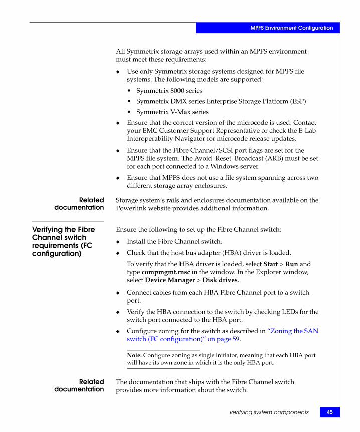
All Symmetrix storage arrays used within an MPFS environment must meet these requirements:
◆ Use only Symmetrix storage systems designed for MPFS file systems. The following models are supported:
• Symmetrix 8000 series
• Symmetrix DMX series Enterprise Storage Platform (ESP)
• Symmetrix V-Max series
◆ Ensure that the correct version of the microcode is used. Contact your EMC Customer Support Representative or check the E-Lab Interoperability Navigator for microcode release updates.
◆ Ensure that the Fibre Channel/SCSI port flags are set for the MPFS file system. The Avoid_Reset_Broadcast (ARB) must be set for each port connected to a Windows server.
◆ Ensure that MPFS does not use a file system spanning across two different storage array enclosures.
Relateddocumentation
Storage system’s rails and enclosures documentation available on the Powerlink website provides additional information.
Verifying the Fibre Channel switch requirements (FC configuration)
Ensure the following to set up the Fibre Channel switch:
◆ Install the Fibre Channel switch.
◆ Check that the host bus adapter (HBA) driver is loaded.
To verify that the HBA driver is loaded, select Start > Run and type compmgmt.msc in the window. In the Explorer window, select Device Manager > Disk drives.
◆ Connect cables from each HBA Fibre Channel port to a switch port.
◆ Verify the HBA connection to the switch by checking LEDs for the switch port connected to the HBA port.
◆ Configure zoning for the switch as described in “Zoning the SAN switch (FC configuration)” on page 59.
Note: Configure zoning as single initiator, meaning that each HBA port will have its own zone in which it is the only HBA port.
Relateddocumentation
The documentation that ships with the Fibre Channel switch provides more information about the switch.

46 EMC Celerra MPFS over FC and iSCSI v5.0 Windows Clients Product Guide
MPFS Environment Configuration
Verifying the IP-SAN switch requirements
The MPFS environment requires a Fibre Channel switch capable of iSCSI-to-Fibre Channel bridging. The following switch characteristics are required:
◆ A iSCSI-to-Fibre Channel bridge that supports the MPFS architecture.
◆ MPFS IP-SAN switches require specific firmware revisions for proper operation.
◆ Verify the SAN OS version with the E-Lab Interoperability Navigator for supported versions.
◆ Install one of the following iSCSI IPS (IP-SAN) modules:
• 8GE IPS blade
• 14FC/2/GE multi protocol services module
• 18FC/4/GE multi protocol services module
Note: The E-Lab Interoperability Navigator contains definitive information on supported software and hardware for Celerra network-attached storage (NAS) products.
Relateddocumentation
Specific IP-SAN switch documentation is a primary source of additional information.
The EMC Celerra MPFS for Windows Clients Release Notes provide a list of supported IP-SAN switches.
Verifying system components 47
MPFS Environment Configuration
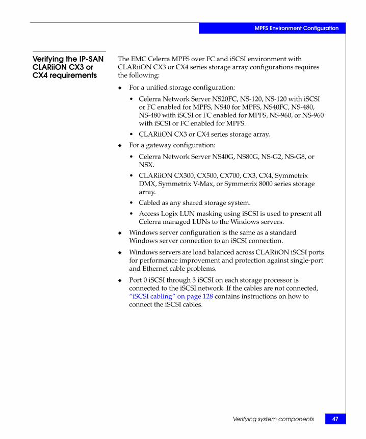
Verifying the IP-SAN CLARiiON CX3 or CX4 requirements
The EMC Celerra MPFS over FC and iSCSI environment with CLARiiON CX3 or CX4 series storage array configurations requires the following:
◆ For a unified storage configuration:
• Celerra Network Server NS20FC, NS-120, NS-120 with iSCSI or FC enabled for MPFS, NS40 for MPFS, NS40FC, NS-480, NS-480 with iSCSI or FC enabled for MPFS, NS-960, or NS-960 with iSCSI or FC enabled for MPFS.
• CLARiiON CX3 or CX4 series storage array.
◆ For a gateway configuration:
• Celerra Network Server NS40G, NS80G, NS-G2, NS-G8, or NSX.
• CLARiiON CX300, CX500, CX700, CX3, CX4, Symmetrix DMX, Symmetrix V-Max, or Symmetrix 8000 series storage array.
• Cabled as any shared storage system.
• Access Logix LUN masking using iSCSI is used to present all Celerra managed LUNs to the Windows servers.
◆ Windows server configuration is the same as a standard Windows server connection to an iSCSI connection.
◆ Windows servers are load balanced across CLARiiON iSCSI ports for performance improvement and protection against single-port and Ethernet cable problems.
◆ Port 0 iSCSI through 3 iSCSI on each storage processor is connected to the iSCSI network. If the cables are not connected, “iSCSI cabling” on page 128 contains instructions on how to connect the iSCSI cables.

48 EMC Celerra MPFS over FC and iSCSI v5.0 Windows Clients Product Guide
MPFS Environment Configuration
Relateddocumentation
The following Celerra installation guides provide more information about hardware installation:
◆ EMC Celerra NS20FC System (Single Blade) Installation Guide Addendum for MPFS
◆ EMC Celerra NS20FC System (Dual Blade) Installation Guide Addendum for MPFS
◆ EMC Celerra NS40 for MPFS System (Single Blade) Installation Guide Addendum for MPFS
◆ EMC Celerra NS40 for MPFS System (Dual Blade) Installation Guide Addendum for MPFS
◆ EMC Celerra NS40FC System (Single Blade) Installation Guide Addendum for MPFS
◆ EMC Celerra NS40FC System (Dual Blade) Installation Guide Addendum for MPFS

Setting up the Celerra Network Server 49
MPFS Environment Configuration
Setting up the Celerra Network ServerThe Celerra Network Server System Software Installation Guide contains information on how to set up the Celerra Network Server, which can be found on the Powerlink website.
50 EMC Celerra MPFS over FC and iSCSI v5.0 Windows Clients Product Guide
MPFS Environment Configuration
Setting up the file systemThis section describes what to do before creating a file system and how to create a file system.
Before creating a file system
This section provides guidelines for storage systems and file system build criteria.
Storage system
CAUTION!Ensure that the file systems used for MPFS do not contain both CLARiiON and Symmetrix LUNs. MPFS does not support a mixed storage environment.
Storage and file system characteristics are very important in high performance grid computing and virtualization environments.
File system build criteriaA properly built file system must:
◆ Use disk volumes from the same storage system.
Note: Do not use a file system spanning across two storage array enclosures. A file system spanning multiple storage systems is not supported even if the multiple storage systems are of the same type, CLARiiON or Symmetrix.
◆ Use disk volumes from the same disk type, all FC or ATA, not a mixture of FC and ATA.
◆ For best MPFS performance, in most cases, configure the Celerra volumes using a volume stripe size of 256 KB. Be sure to review the EMC Celerra MPFS over iSCSI Applied Best Practices Guide for detailed performance related information.
◆ In a Symmetrix environment, ensure that the Symmetrix Fibre Channel/SCSI port flag settings are properly configured for the MPFS file system; in particular, the ARB flag must be set. Your EMC Customer Support Representative configures these settings.

Setting up the file system 51
MPFS Environment Configuration
Creating a file system on a Celerra Network Server
This section describes how to configure, create, mount, and export file systems.
Make sure LUNs for the new file system are created optimally for MPFS. All LUNs must:◆ Be of the same RAID type ◆ Have the same number of spindles in each RAID group◆ Contain spindles of the same type and speed
In addition, make sure that all LUNs do not share spindles with: ◆ Other LUNs in the same file system◆ Another file system heavily utilized by high-I/O applications
Before creating the LUNs, ensure that the total usable capacity of all the LUNs within a single file system does not exceed 16 TB. The maximum number of LUNs tested that are supported in MPFS configurations per file system is 256. Ensure that the LUNs are accessible by the Data Movers through LUN masking, switch zoning, and VSAN settings.
Use this procedure to build or mount the MPFS file system on the Celerra Network Server:
1. Log in to the Celerra Network Server Control Station as NAS administrator.
2. Before building the file system, type the nas_disk command to return a list of disks not in use. Use this command syntax:
$ nas_disk -list | grep n | more
For example, type:
$ nas_disk -l

52 EMC Celerra MPFS over FC and iSCSI v5.0 Windows Clients Product Guide
MPFS Environment Configuration
The output is similar to this:
The first stripe alternate SP ownership A,B,A,B,A,B is displayed in bold text and the second stripe alternate SP ownership B,A,B,A,B,A is displayed in a shaded background. The two different stripes (A, B, A) and (B, A, B) are both in RAID group X, Y, and Z.
Note: Use Navicli or EMC Navisphere® Manager to determine which LUNs are on SP A and SP B.
id inuse sizeMB storageID-devID type name servers1 y 11263 APM00065101342-0000 CLSTD root_disk 1,22 y 11263 APM00065101342-0001 CLSTD root_disk 1,23 y 2047 APM00065101342-0002 CLSTD d3 1,24 y 2047 APM00065101342-0003 CLSTD d4 1,25 y 2047 APM00065101342-0004 CLSTD d5 1,26 y 2047 APM00065101342-0005 CLSTD d6 1,27 n 466747 APM00065101342-0010 CLSTD d7 1,28 n 466747 APM00065101342-0011 CLSTD d8 1,29 n 549623 APM00065101342-0012 CLSTD d9 1,210 n 549623 APM00065101342-0014 CLSTD d10 1,211 n 549623 APM00065101342-0016 CLSTD d11 1,212 n 549623 APM00065101342-0018 CLSTD d12 1,213 n 549623 APM00065101342-0013 CLSTD d13 1,214 n 549623 APM00065101342-0015 CLSTD d14 1,215 n 549623 APM00065101342-0017 CLSTD d15 1,216 n 549623 APM00065101342-0019 CLSTD d16 1,217 n 549623 APM00065101342-001A CLSTD d17 1,218 n 549623 APM00065101342-001B CLSTD d18 1,219 n 549623 APM00065101342-001C CLSTD d19 1,220 n 549623 APM00065101342-001E CLSTD d20 1,221 n 549623 APM00065101342-0020 CLSTD d21 1,222 n 549623 APM00065101342-001D CLSTD d22 1,223 n 549623 APM00065101342-001F CLSTD d23 1,224 n 549623 APM00065101342-0021 CLSTD d24 1,225 n 549623 APM00065101342-0022 CLSTD d25 1,226 n 549623 APM00065101342-0024 CLSTD d26 1,227 n 549623 APM00065101342-0026 CLSTD d27 1,228 n 549623 APM00065101342-0023 CLSTD d28 1,229 n 549623 APM00065101342-0025 CLSTD d29 1,230 n 549623 APM00065101342-0027 CLSTD d30 1,2

Setting up the file system 53
MPFS Environment Configuration
3. Create the first stripe. Use this command syntax:$ nas_volume -name <name> -create -Stripe
<stripe_size> <volume_set>,...
where:<name> = name of the volume<stripe_size> = size of the stripe<volume_set> = set of disks
For example, to create a stripe pair with a depth of 262144 bytes (256 KB), type:
# nas_volume -name s2_stripe1 -create -Stripe 262144 d9,d14,d11,d16,d17,d22
The output is similar to this:
id = 135name = s2_stripe1acl = 0in_use = Falsetype = stripestripe_size = 262144volume_set = d9,d14,d11,d16,d17,d22disks = d9,d14,d11,d16,d17,d22
Note: For best MPFS performance, in most cases, configure the Celerra volumes using a volume stripe size of 256 KB. Detailed performance-related information is available in the EMC Celerra MPFS over iSCSI Applied Best Practices Guide.
4. Create second stripe. Use this command syntax:$ nas_volume -name <name> -create -Stripe
<stripe_size> <volume_set>,...
where:<name> = name of the volume<stripe_size> = size of the stripe<volume_set> = set of disks
For example, to create a stripe pair with a depth of 262144 bytes (256 KB), type:
# nas_volume -name s2_stripe2 -create -Stripe 262144
d13,d10,d15,d12,d18,d19

54 EMC Celerra MPFS over FC and iSCSI v5.0 Windows Clients Product Guide
MPFS Environment Configuration
The output is similar to this:
id = 136name = s2_stripe2acl = 0in_use = Falsetype = stripestripe_size = 262144volume_set = d13,d10,d15,d12,d18,d19disks = d13,d10,d15,d12,d18,d19
5. Create the metavolume. Use this command syntax:$ nas_volume -name <name> -create -Meta <volume_name>
where:<name> = assigns this name to a file system<volume_name> = name of the volume
For example, type:
# nas_volume -name s2_metal -create -Meta s2_stripe1, s2_stripe2
The output is similar to this:
id = 137name = s2_meta1acl = 0in_use = Falsetype = metavolume_set = s2_stripe1, s2_stripe2disks =
d9,d14,d11,d16,d17,d22,d13,d10,d15,d12,d18,d19
6. Create the file system. Use this command syntax:$ nas_fs -name <name> -create <volume_name>
where:<name> = assigns this name to a file system<volume_name> = name of the volume
For example, type:
# nas_fs -name s2fs1 -create s2_meta1
The output is similar to this:
id = 33name = s2fs1acl = 0in_use = Falsetype = uxfsworm = compliance
Setting up the file system 55
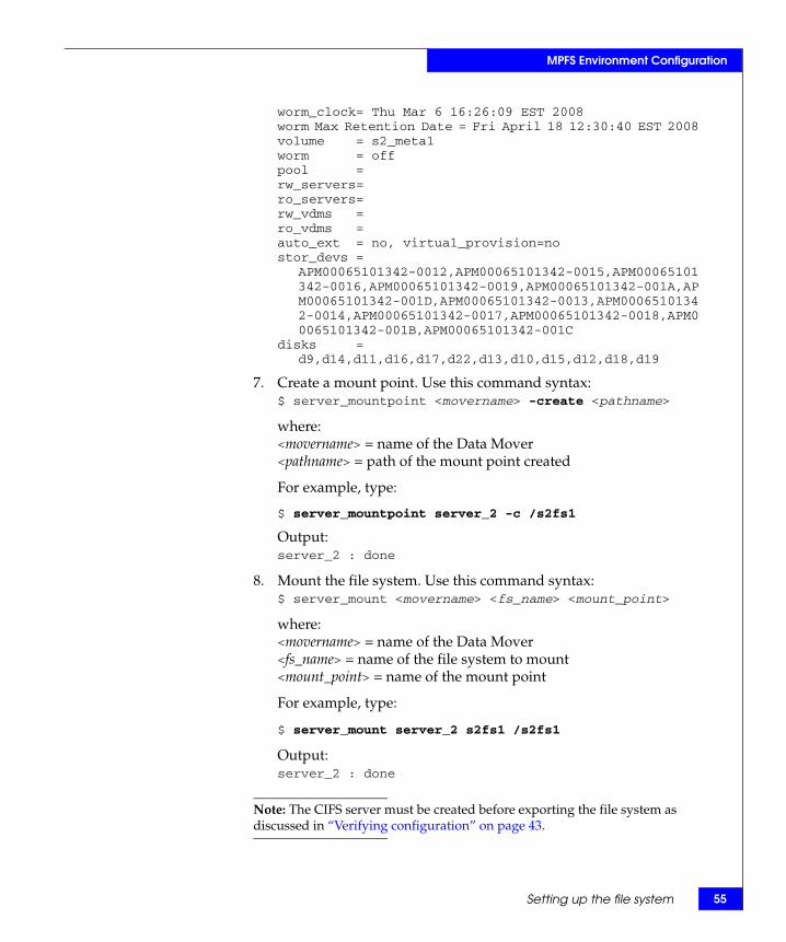
MPFS Environment Configuration
worm_clock= Thu Mar 6 16:26:09 EST 2008worm Max Retention Date = Fri April 18 12:30:40 EST 2008volume = s2_meta1worm = offpool = rw_servers= ro_servers= rw_vdms = ro_vdms = auto_ext = no, virtual_provision=nostor_devs =
APM00065101342-0012,APM00065101342-0015,APM00065101342-0016,APM00065101342-0019,APM00065101342-001A,APM00065101342-001D,APM00065101342-0013,APM00065101342-0014,APM00065101342-0017,APM00065101342-0018,APM00065101342-001B,APM00065101342-001C
disks = d9,d14,d11,d16,d17,d22,d13,d10,d15,d12,d18,d19
7. Create a mount point. Use this command syntax:$ server_mountpoint <movername> -create <pathname>
where:<movername> = name of the Data Mover<pathname> = path of the mount point created
For example, type:
$ server_mountpoint server_2 -c /s2fs1
Output:server_2 : done
8. Mount the file system. Use this command syntax:$ server_mount <movername> <fs_name> <mount_point>
where:<movername> = name of the Data Mover<fs_name> = name of the file system to mount<mount_point> = name of the mount point
For example, type:
$ server_mount server_2 s2fs1 /s2fs1
Output:server_2 : done
Note: The CIFS server must be created before exporting the file system as discussed in “Verifying configuration” on page 43.

56 EMC Celerra MPFS over FC and iSCSI v5.0 Windows Clients Product Guide
MPFS Environment Configuration
9. Export the file system. Use this command syntax:$ server_export <mover_name> -Protocol nfs -name
<name> -option <options> <pathname>
where:<movername> = name of the Data Mover<name> = assigns an alias for the <pathname><options> = options to include<pathname> = path of the mount point created
For example, type:
$ server_export server_2 -P nfs -name ufs1 /ufs1
Output:server_2 : done
Relateddocumentation
The following documents contain more information on building the MPFS file system and are available on the EMC Powerlink website:
◆ Celerra Network Server Command Reference Manual
◆ Configuring and Managing Celerra Networking
◆ Managing Celerra Volumes and File Systems Manually
◆ Using MPFS on Celerra

Enabling MPFS for the Celerra Network Server 57
MPFS Environment Configuration
Enabling MPFS for the Celerra Network ServerStart MPFS on the Celerra Network Server. Use this command syntax:
$ server_setup <movername> -Protocol mpfs -option <options>
where:<movername> = name of the Data Mover<options> = options to include
Type:$ server_setup server_2 -Protocol mpfs -option start
Output:server_2 : done
Note: Start MPFS on the same Data Mover you exported the file system using CIFS.

58 EMC Celerra MPFS over FC and iSCSI v5.0 Windows Clients Product Guide
MPFS Environment Configuration
Configuring the CLARiiON using CLI commandsThis section presents an overview of configuring the CLARiiON CX3 or CX4 array ports mounted on the CLARiiON storage array for Celerra gateway configurations. Use site-specific parameters for these steps.
The configuration of CLARiiON CX3 or CX4 array ports for Celerra gateway is done using the CLI commands.
Best practices To simplify the configuration and management of the Windows server, EMC recommends that the discovery addresses (IP addresses) and enabled targets for each Windows server be configured so that all the iSCSI target ports on the storage array are equally balanced to achieve maximum performance and availability. Balancing the load across all ports enables speeds up to 4 x 10 Gb/s per storage processor. If one of the iSCSI target ports fails, the other three will remain operational, so one-fourth of the Windows servers will fail over to the native NFS or CIFS protocol, but three-fourths of the Windows servers will continue operating at higher speeds attainable through iSCSI.
CLARiiON discovery sessions reveal paths to all four iSCSI ports on each storage processor. The ports are described to the iSCSI initiators as individual targets. Each of these connections creates another session. The current maximum number of initiator sessions or hosts per storage processor is 128 for the CLARiiON CX3, 256 for the CLARiiON CX4-120, 512 for the CLARiiON CX 4-240, 1024 for the CLARiiON CX4-480, and 4096 for the CLARiiON CX4-960. Without disabling other iSCSI targets, a CLARiiON cannot support more than 32 iSCSI initiators. To increase the number of achievable Windows servers for a Celerra gateway, disable access on each Windows server to as many as three out of four iSCSI targets per storage processor and ensure that the enabled iSCSI targets (CLARiiON iSCSI ports) match the storage group definition.

Configuring the SAN and storage 59
MPFS Environment Configuration
For Celerra gateway configurations, Access Logix LUN masking using iSCSI is used to present all Celerra managed LUNs to the Windows servers. The non-Celerra LUNs are protected from the iSCSI initiators. A separate storage group is created for MPFS initiators and all Celerra LUNs that are not Celerra Control LUNs are added to this group. At least one port from each SP should be enabled for each Windows server in this group.
In a gateway environment, iSCSI initiator names are used in providing the path in the storage group for the Windows server to access the iSCSI targets. Unique, known iSCSI names are required for using Access Logix software.
Configuring the SAN and storageThis section describes how to configure the SAN switch along with specific configuration information for Symmetrix and CLARiiON storage arrays.
Installing the Fibre Channel switch (FC configuration)
To set up the Fibre Channel switch, complete these tasks:
1. Install the Fibre Channel switch (if not already installed).
2. Connect cables from each HBA Fibre Channel port to a switch port.
3. Verify the HBA connection to the switch by checking the LEDs for the switch port connected to the HBA port.
Note: Configure zoning as single initiator, meaning that each HBA port will have its own zone in which it is the only HBA port.
Zoning the SAN switch (FC configuration)
This section presents an overview of configuring and zoning a Fibre Channel switch:
1. Record all attached port WWNs.
2. Log in to the iSCSI-to-Fibre Channel bridge or MDS Fibre Channel switch console using CLI commands or the Fabric Manager.
3. Create a zone for each Fibre Channel HBA port and its associated Fibre Channel Target.

60 EMC Celerra MPFS over FC and iSCSI v5.0 Windows Clients Product Guide
MPFS Environment Configuration
Relateddocumentation
The documentation that ships with the Fibre Channel switch contains additional information on installing or zoning.
Note: Configure the CLARiiON so that each target is zoned to an SP A and SP B port. Configure the Symmetrix so that it is zoned to a single Fibre Channel Director (FA).
Configuring the iSCSI-to-Fibre Channel bridge (iSCSI configuration)
This section presents an overview of configuring and zoning the iSCSI-to-Fibre Channel bridge for an iSCSI configuration. Use site-specific parameters for these steps.
When configuring the iSCSI-to-Fibre Channel bridge for an iSCSI configuration:
◆ The EMC Celerra MPFS over iSCSI configuration does not use the EMC Celerra iSCSI target feature. It relies on the iSCSI initiator and an IP-SAN compatible switch as the iSCSI target to bridge traffic to Fibre Channel. Use “Verifying the IP-SAN switch requirements” on page 46 to identify supported switch models.
◆ The MDS management port must be connected to a different LAN from the iSCSI ports. When properly configured, the iSCSI ports should not be able to ping the MDS management port.
◆ Configure zoning as a single initiator. Each zone entity will contain one initiator and one target HBA. Each server will also have its own zone.
The documents listed in “Related documentation” on page 56 provide additional information.
Enabling iSCSI on theMDS console (iSCSI
configuration)
To enable iSCSI on the MDS console:
1. Enable iSCSI and add the iSCSI interface to the VSAN:
switch # config t switch(config)# iscsi enableswitch(config)# iscsi interface vsan-membership
2. Import the Fibre Channel targets so the MDS console can communicate with the iSCSI initiator and set the authentication:
switch(config)# iscsi import target fcswitch(config)# iscsi authentication none

Configuring the SAN and storage 61
MPFS Environment Configuration
Configuring the MDSiSCSI port for Gigabit
Ethernet (iSCSIconfiguration)
Configure the MDS iSCSI port as a normal Gigabit Ethernet port:
switch(config)# interface GigabitEthernet2/1switch(config-if)# <port IP address> <subnet mask>switch(config-if)# iscsi authentication noneswitch(config-if)# no shutdownswitch(config-if)# exitswitch(config)# ip routingswitch(config)#
Note: The iSCSI-to-Fibre Channel bridge can also be configured and managed through the Fabric Manager GUI.
The EMC Celerra MPFS over iSCSI Applied Best Practices Guide describes best practices for configuring the MDS iSCSI port for Gigabit Ethernet and can be found on the Powerlink website.
Configuring the iSCSIport proxy and TCP
parameters (iSCSIconfiguration)
Configure the iSCSI-to-Fibre Channel bridge to act as a proxy initiator so that the CLARiiON storage array does not need to be configured with the World Wide Names (WWNs) for all the initiators:
1. Set the iSCSI-to-Fibre Channel bridge to act as a proxy initiator:
switch(config)# interface iscsi2/1switch(config-if)# switchport proxy-initiator switch(config-if)#
2. Set the TCP parameters:
switch(config-if)# tcp send-buffer-size 16384switch(config-if)# no shutdownswitch(config-if)# exitswitch(config)# exitswitch #
3. Retrieve the system-assigned www names by typing:
switch # show interface iscsi2/1
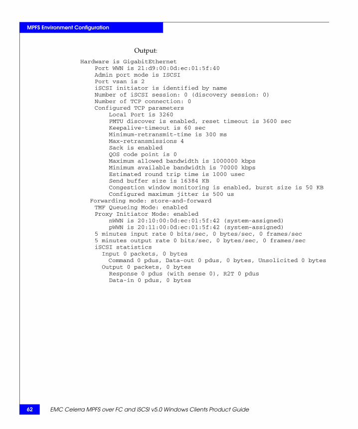
62 EMC Celerra MPFS over FC and iSCSI v5.0 Windows Clients Product Guide
MPFS Environment Configuration
Output:
Hardware is GigabitEthernet Port WWN is 21:d9:00:0d:ec:01:5f:40 Admin port mode is ISCSI Port vsan is 2 iSCSI initiator is identified by name Number of iSCSI session: 0 (discovery session: 0) Number of TCP connection: 0 Configured TCP parameters Local Port is 3260 PMTU discover is enabled, reset timeout is 3600 sec Keepalive-timeout is 60 sec Minimum-retransmit-time is 300 ms Max-retransmissions 4 Sack is enabled QOS code point is 0 Maximum allowed bandwidth is 1000000 kbps Minimum available bandwidth is 70000 kbps Estimated round trip time is 1000 usec Send buffer size is 16384 KB Congestion window monitoring is enabled, burst size is 50 KB Configured maximum jitter is 500 us
Forwarding mode: store-and-forward TMF Queueing Mode: enabled Proxy Initiator Mode: enabled nWWN is 20:10:00:0d:ec:01:5f:42 (system-assigned) pWWN is 20:11:00:0d:ec:01:5f:42 (system-assigned) 5 minutes input rate 0 bits/sec, 0 bytes/sec, 0 frames/sec 5 minutes output rate 0 bits/sec, 0 bytes/sec, 0 frames/sec iSCSI statistics Input 0 packets, 0 bytes Command 0 pdus, Data-out 0 pdus, 0 bytes, Unsolicited 0 bytes Output 0 packets, 0 bytes Response 0 pdus (with sense 0), R2T 0 pdus Data-in 0 pdus, 0 bytes
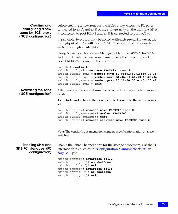
Configuring the SAN and storage 63
MPFS Environment Configuration
Creating andconfiguring a new
zone for iSCSI proxy(iSCSI configuration)
Before creating a new zone for the iSCSI proxy, check the FC ports connected to SP A and SP B of the storage array. In the example, SP A is connected to port FC4/2 and SP B is connected to port FC4/4.
In principle, two ports may be zoned with each proxy. However, the throughput of iSCSI will be still 1 Gb. One port must be connected to each SP for high availability.
Using Navicli or Navisphere Manager, obtain the pWWN for SP A and SP B. Create the new zone named using the name of the iSCSI port. PROXY2-1 is used in the example:
switch # config tswitch(config)# zone name PROXY2-1 vsan 2switch(config-zone)# member pwwn 50:06:01:60:10:60:20:35 switch(config-zone)# member pwwn 50:06:01:60:10:60:20:3eswitch(config-zone)# member pwwn 20:11:00:0d:ec:01:5f:42 switch(config-zone)# exit
Activating the zone(iSCSI configuration)
After creating the zone, it must be activated for the switch to know it exists.
To include and activate the newly created zone into the active zones, set:
switch(config)# zoneset name PROXIES vsan 2switch(config-zoneset)# member PROXY2-1switch(config-zoneset)# exitswitch(config)# zoneset activate name PROXIES vsan 2
Note: The vendor’s documentation contains specific information on these switches.
Enabling SP A andSP B FC interfaces (FC
configuration)
Enable the Fibre Channel ports for the storage processors. Use the FC interface data collected in “Configuration planning checklist” on page 38. Type:
switch(config)# interface fc4/2switch(config-if)# no shutdownswitch(config-if)# exitswitch(config)# interface fc4/4switch(config-if)# no shutdownswitch(config-if)# exit

64 EMC Celerra MPFS over FC and iSCSI v5.0 Windows Clients Product Guide
MPFS Environment Configuration
Adding a VSAN foriSCSI/FC and enabling
zones
Use the following example to add the iSCSI blade in slot 2, port 1 and Fibre Channel (FC) blade in slot 4, ports 2 and 4 to MDS VSAN 2. Then, enable the default zone to permit VSANs 1-4093:
1. Add a VSAN for iSCSI and Fibre Channel to the iSCSI-to-Fibre Channel bridge:
switch(config)# show vsan database switch(config-vsan-db)# vsan 2switch(config-vsan-db)# vsan 2 interface iscsi2/1switch(config-vsan-db)# vsan 2 interface fc4/4
switch(config-vsan-db)# vsan 2 interface fc4/2switch(config-vsan-db)# exit
2. Enable zones on the iSCSI-to-Fibre Channel bridge:
switch(config)# zone default-zone permit vsan 1-4093
3. Log off the iSCSI-to-Fibre Channel bridge or MDS Fibre Channel switch console:
switch(config)# exit
Creating a security file on the Celerra Network Server
A storage system will not accept a Secure CLI command unless the user who issues the command has a valid user account on the storage system. You can configure a Navisphere 6.X security file to issue Secure CLI commands on the server. Secure CLI commands require the servers (or the password prompt) in each command line; you do not need to provide these in the command line if you create a security file.
To create a security file:
1. Log in to the Celerra Network Server Control Station as NAS administrator.
2. If you use the same settings for the username and passwords, as done on the switch, type:
/nas/sbin/naviseccli -h <hostname:IP address> security -AddUserSecurity -scope 0 -user nasadmin -password nasadmin
Note: Specify the hostname as SP A or SP B.

Configuring the SAN and storage 65
MPFS Environment Configuration
3. If you are using a new CLARiiON storage array with NAS v5.5 and content running in non-secure mode, type:
/nas/sbin/naviseccli -h <hostname:IP address> security -AddUserSecurity -scope 0 -user emc -password emc
CLARiiON iSCSI port configuration
This section describes how to set up the CLARiiON storage array for an iSCSI configuration:
Note: The IP addresses of all storage arrays <hostname:IP address> can be found in the /etc/hosts file on the Celerra Control Station. If multiple arrays are used, EMC recommends registering them in the /etc/hosts file.
1. Use the following naviseccli command to configure iSCSI target hostname SP A, port IP address 0 on the storage array:
/nas/sbin/naviseccli -h <hostname:IP address> connection -setport -sp a -portid 0 -address <port IP address> -subnetmask <subnet mask> -gateway <gateway IP address>
It is recommended that you consult with your Network Manager to determine the correct settings before applying these changes. Changing the port properties may disrupt iSCSI traffic to all ports on this SP. Initiator configuration changes may be necessary to regain connections. Do you really want to perform this action (y/n)? y
2. Continue for SP A ports 1–3 and SP B ports 0–3:
/nas/sbin/naviseccli -h <hostname:IP address> connection -setport -sp a -portid 1 -address <port IP address> -subnetmask <subnet mask> -gateway <gateway IP address>
/nas/sbin/naviseccli -h <hostname:IP address> connection -setport -sp a -portid 2 -address <port IP address> -subnetmask <subnet mask> -gateway <gateway IP address>
/nas/sbin/naviseccli -h <hostname:IP address> connection -setport -sp a -portid 3 -address <port IP address> -subnetmask <subnet mask> -gateway <gateway IP address>
/nas/sbin/naviseccli -h <hostname:IP address> connection -setport -sp b -portid 0 -address <port IP address> -subnetmask <subnet mask> -gateway <gateway IP address>
66 EMC Celerra MPFS over FC and iSCSI v5.0 Windows Clients Product Guide
MPFS Environment Configuration
/nas/sbin/naviseccli -h <hostname:IP address> connection -setport -sp b -portid 1 -address <port IP address> -subnetmask <subnet mask> -gateway <gateway IP address>
/nas/sbin/naviseccli -h <hostname:IP address> connection -setport -sp b -portid 2 -address <port IP address> -subnetmask <subnet mask> -gateway <gateway IP address>
/nas/sbin/naviseccli -h <hostname:IP address> connection -setport -sp b -portid 3 -address <port IP address> -subnetmask <subnet mask> -gateway <gateway IP address>
Access Logix configuration
This section describes how to configure an Access Logix configuration, create storage groups, add LUNs, and set failovermode and the arraycommpath.
Setting failovermodeand the
arraycommpath usingAccess Logix
The naviseccli failovermode command enables or disables the type of trespass needed for the failover software. This method of setting -failovermode works for storage systems with Access Logix only.
To discover the current setting of failovermode, use the port-list-failovermode or port-list-all command:
CAUTION!Changing the failovermode setting may force the storage system to reboot. Changing the failovermode to the wrong value will make the storage group inaccessible to any connected server.
1. To set failovermode to 1 (unified storage only), type:
/nas/sbin/naviseccli -h <hostname:IP address> failovermode 1
WARNING: Previous Failovermode setting will be lost!DO YOU WISH TO CONTINUE (y/n)? y
2. To set arraycommpath to 1 (unified storage only), type:
/nas/sbin/naviseccli -h <hostname:IP address> arraycommpath 1

Configuring the SAN and storage 67
MPFS Environment Configuration
WARNING: Previous Arraycommpath setting will be lost!DO YOU WISH TO CONTINUE (y/n)? y
The above commands enable failovermode and arraycommpath for the storage system.
Creating storagegroups and adding
LUNs
This section describes how to create storage groups, add LUNS to the storage groups, and configure the storage groups.
The IP addresses of all storage arrays <hostname:IP address> can be found in the /etc/hosts file on the Celerra Control Station. If multiple arrays are used, EMC recommends registering them in the /etc/hosts file:
Note: Specify the hostname as SP A or SP B.
1. Create the storage group:
$ /nas/sbin/navicli -h <hostname:IP address> storagegroup -create -gname MPFS_Clients
2. Add LUNs to the storage group:
$ /nas/sbin/navicli -h <hostname:IP address> storagegroup - addhlu -gname MPFS_Clients -hlu 0 -alu 16
3. Continue for all LUNs:
$ /nas/sbin/navicli -h <hostname:IP address> storagegroup - addhlu -gname MPFS_Clients -hlu 1 -alu 17

68 EMC Celerra MPFS over FC and iSCSI v5.0 Windows Clients Product Guide
MPFS Environment Configuration
Installing the MPFS softwareThis section describes the requirements necessary before installing and how to install the MPFS software from Powerlink or the EMC MPFS for Windows Client CD.
Before installing Before installing the MPFS software, read the prerequisites for the Windows server and storage system, listed in this section.
❑ Verify that the Windows server on which you plan to install the MPFS software meets the MPFS configuration requirements specified in the EMC Celerra MPFS for Windows Clients Release Notes.
❑ Ensure that the Windows server has a network connection to the Data Mover on which the MPFS software resides and that you can contact the Data Mover.
❑ Ensure that the Windows server meets the overall system and other configuration requirements specified in the E-Lab Interoperability Navigator.
CAUTION!Install the Windows server before installing the Microsoft iSCSI Initiator. This will protect Celerra disks from being inadvertently overwritten.
CAUTION!Cancel the Initialize and Convert the Disk Wizard when starting the Disk Manager Microsoft Management Console.

Installing the MPFS software 69
MPFS Environment Configuration
Installing the MPFS software
To install the MPFS software:
1. Create a directory on the local machine for the MPFS software files.
2. Locate the Windows executable file on the EMC Powerlink website at http://Powerlink.EMC.com or on the EMC MPFS for Windows Client Software CD.
3. Download the executable file from Powerlink or from the EMC MPFS for Windows Client Software CD to the directory created in step 1.
4. Double-click the appropriate executable file as listed in Table 4 on page 69.
Table 4 MPFS executable files with Windows OS versions
OSService Pack Executable filea
Windows 2000 Serverb SP4 EMCmpfs.win.<version>.win32.Win2000.exe
Windows Server 2003 32 bit SP2 EMCmpfs.win.<version>.win32.Win2003.exe
Windows Server 2003 64 bit SP2 EMCmpfs.win.<version>.x64.Win2003.exe
Windows Server 2003 R2 32 bit SP2 EMCmpfs.win.<version>.win32.Win2003.exe
Windows Server 2003 R2 64 bit SP2 EMCmpfs.win.<version>.x64.Win2003.exe
Windows Server 2008 32 bit SP1 EMCmpfs.win.<version>.win32.Win2008.exe
Windows Server 2008 64 bit SP1 EMCmpfs.win.<version>.x64.Win2008.exe
Windows XP Professional 32 bitc SP3 EMCmpfs.win.<version>.win32.WinXP.exe
Windows XP Professional 64 bitc SP2 EMCmpfs.win.<version>.x64.WinXP.exe
Windows Vista 32 bit SP2 EMCmpfs.win.<version>.win32.Vista.exe
Windows Vista 64 bit SP2 EMCmpfs.win.<version>.x64.Vista.exe
a. Where <version> is the MPFS software version number.
b. Fibre Channel only.
c. iSCSI only.

70 EMC Celerra MPFS over FC and iSCSI v5.0 Windows Clients Product Guide
MPFS Environment Configuration
5. The Information window appears before the installation begins as shown in Figure 8 on page 70. Check that UDP ports 625–635 are not blocked by a firewall and click OK to start the installation.
Figure 8 Information window before Install
6. The EMC MPFS Installer dialog box appears as shown in Figure 9 on page 70.
Figure 9 EMC MPFS Installer dialog box
7. In the EMC MPFS Installer dialog box, type the install directory, if different from the default directory (C:\Program Files\EMC). Click Install.

Installing the MPFS software 71
MPFS Environment Configuration
8. When the installation is complete, the message shown in Figure 10 on page 71 appears.
Figure 10 EMC MPFS is Installed dialog box
9. Click Yes to restart the computer.
Note: Restart the Windows server after the MPFS software is installed.
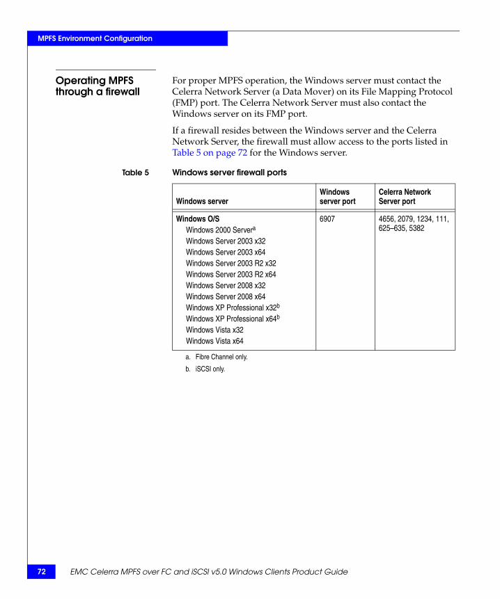
72 EMC Celerra MPFS over FC and iSCSI v5.0 Windows Clients Product Guide
MPFS Environment Configuration
Operating MPFS through a firewall
For proper MPFS operation, the Windows server must contact the Celerra Network Server (a Data Mover) on its File Mapping Protocol (FMP) port. The Celerra Network Server must also contact the Windows server on its FMP port.
If a firewall resides between the Windows server and the Celerra Network Server, the firewall must allow access to the ports listed in Table 5 on page 72 for the Windows server.
Table 5 Windows server firewall ports
Windows server Windows server port
Celerra Network Server port
Windows O/SWindows 2000 Servera
Windows Server 2003 x32Windows Server 2003 x64Windows Server 2003 R2 x32Windows Server 2003 R2 x64Windows Server 2008 x32Windows Server 2008 x64Windows XP Professional x32b
Windows XP Professional x64b
Windows Vista x32Windows Vista x64
6907 4656, 2079, 1234, 111, 625–635, 5382
a. Fibre Channel only.
b. iSCSI only.

Configuring and accessing storage 73
MPFS Environment Configuration
Configuring and accessing storageThis section describes how to install the Fibre Channel driver, the Microsoft iSCSI initiator, and add initiators to the storage group.
Note: EMC recommends to view the iSCSI disks using the Windows Device Manager. This method of viewing iSCSI disks will not expose the Celerra disks to Windows operations.
The arraycommpath and failovermode settings are used to see both active and passive paths concurrently. For a LUN failover, LUNs can be presented from active to passive path or passive to active path. Use arraycommpath and failovermode settings as described in Table 6 on page 73.
When using the MDS in proxy-initiator mode, the storage group should contain the WWN of the MDS proxy-initiator ports, not the Windows servers.
When using the CLARiiON CX3 or CX4 series storage array in an iSCSI configuration, the iSCSI initiator name, or IQN, is used to define the server, not a WWN.
Installing the Fibre Channel driver (FC configuration)
Install the Fibre Channel driver on the Windows server. The latest driver and qualification information is available on the Fibre Channel manufacturer’s website, the E-Lab Interoperability Navigator, or the documentation provided with the Fibre Channel driver.
Table 6 Correct arraycommpath and failovermode settings
Celerraports
Windows servers/ MDS proxy-initiators
Gateway units with Access Logiix
arraycommpath 0 1
failovermode 0 1
Unified storage, MPFS capable units
arraycommpath 0 1
failovermode 0 1

74 EMC Celerra MPFS over FC and iSCSI v5.0 Windows Clients Product Guide
MPFS Environment Configuration
Adding Fibre Channelhosts to the storage
group (FCconfiguration)
Use the following steps to view hosts in the storage group and add hosts to the storage group for SP A and SP B:
1. Use the following navicli command to list the hosts in the storage group:
$ /nas/sbin/navicli -h <hostname:IP address> port -list |grep "HBA UID:"
The output is similar to this:
HBA UID: 20:01:00:1B:32:20:D1:3A:21:01:00:1B:32:20:D1:3AHBA UID: 20:00:00:1B:32:00:D1:3A:21:00:00:1B:32:00:D1:3AHBA UID: 20:01:00:1B:32:20:B5:35:21:01:00:1B:32:20:B5:35HBA UID: 20:00:00:1B:32:00:B5:35:21:00:00:1B:32:00:B5:35
2. Use the following navicli command to add hosts to the storage group using this command syntax:
$ /nas/sbin/navicli -h <hostname:IP address> storagegroup -setpath -gname <gname> -hbauid <hbauid> -sp <sp> -spport <spport> -failovermode <failovermode> -arraycommpath <arraycommpath>
where:
For example:
$ /nas/sbin/navicli -h <xxx.xxx.xx.x> storagegroup -setpath -gname MPFS_Clients -hbauid 20:0a:00:0d:ec:01:53:82:20:09:00:0d:ec:01:53:82 -sp a -spport 0 -failovermode 1 -arraycommpath 1
<gname> = storage group name<hbauid> = WWN of proxy initiator<sp> = storage processor<spport> = port on SP<failovermode> = enables or disables the type of trespass
needed for failover software (1 = enable, 0 = disable)
<arraycommpath> = creates or removes a communication path between the host and the storage system (1 = enable, 0 = disable)

Configuring and accessing storage 75
MPFS Environment Configuration
3. Perform this command for SP A and SP B.
Note: The IP addresses of all storage arrays <hostname:IP address> can be found in the /etc/hosts file on the Celerra Control Station. If multiple arrays are used, EMC recommends registering them in the /etc/hosts file.
The output is similar to this:
list host wwn
$ /nas/sbin/navicli -h <hostname:IP address> storagegroup -stepath -gname MPFS_Clients -hbauid 20:0a:00:0d:ec:01:53:82:20:09:00:0d:ec:01:53:82 -sp a -spport 0 -failovermode 1 -arraycommpath 1
The recommended configuration is to have all HBAs on one host mapped to the same storage group.
Set Path to storage group MPFS_Clients (y/n)? y WARNING: Changing configuration options may cause the
array to stop functioningcorrectly. Failover-related Initiator settings for a
single host MUST BE CONSISTENTfor all paths from the host to the storage system. Please
verify after reconnect.Do you wish to continue (y/n)? y $ /nas/sbin/navicli -h <hostname:IP address> storagegroup
-stepath -gname MPFS_Clients -hbauid 20:0a:00:0d:ec:01:53:82:20:09:00:0d:ec:01:53:82 -sp a -spport 0 -failovermode 1 -arraycommpath 1
The recommended configuration is to have all HBAs on one
host mapped to the same storage group. Set Path to storage group MPFS_Clients (y/n)? y WARNING: Changing configuration options may cause the
array to stop functioningcorrectly. Failover-related Initiator settings for a
single host MUST BE CONSISTENTfor all paths from the host to the storage system. Please
verify after reconnect.Do you wish to continue (y/n)? y
76 EMC Celerra MPFS over FC and iSCSI v5.0 Windows Clients Product Guide
MPFS Environment Configuration
Installing and configuring the initiator (iSCSI configuration)
The Microsoft iSCSI Software Initiator User Guide, which is installed with the Microsoft iSCSI Initiator, provides detailed configuration information. Install and configure the iSCSI initiator by performing the following tasks:
◆ Install the Microsoft iSCSI Initiator.
◆ Register the initiator name with the Windows Registry.
◆ Configure the CHAP secret for reverse authentication (optional).
◆ Configure iSCSI discovery on the initiator.
◆ Log in to the iSCSI target.
Install the MicrosoftiSCSI Initiator (iSCSI
configuration)
To connect to the iSCSI targets on a Windows server, the server requires an iSCSI initiator. Celerra iSCSI supports the Microsoft iSCSI Software Initiator:
1. Download the latest Microsoft iSCSI Software Initiator from the Microsoft website.
2. Run the initiator executable.The Welcome to Microsoft iSCSI Initiator Setup Wizard dialog box appears.
3. Click Next.
4. In the Select Installation Folder dialog box, select Everyone, and then do one of the following:
• To accept the default installation folder, click Next.
• To use another folder for installation, click Browse to locate the folder, and then click Next.
5. In the Confirm Installation dialog box, click Next.
6. In the License Agreement dialog box, select I Agree,
7. Click Next.
8. In the Microsoft iSCSI Installation Program dialog box, click OK to install the complete iSCSI initiator.
9. In the End User License Agreement dialog box, click Agree to accept the terms of the license agreement.

Configuring and accessing storage 77
MPFS Environment Configuration
10. To complete the installation:
a. Click OK to close the installation confirmation message.
b. At the Microsoft iSCSI Initiator Information dialog box, click Next.
c. At the Installation Complete dialog box, click Close.
Register the initiatorname (iSCSI
configuration)
Complete this procedure for each iSCSI initiator that needs to connect to a Celerra Network Server. If the initiator’s iSCSI Qualified Name (IQN) is not written to the Windows Registry, iSCSI-aware applications might not find the initiator’s IQN:
1. Open the Microsoft iSCSI Initiator.
2. Click General to check the version shown.
3. In the Initiator Node Name Change window, leave the displayed initiator name unchanged. Click OK.
This procedure converts uppercase characters in the IQN to lowercase. The Celerra Network Server supports only lowercase IQNs.
Configure the CHAPsecret for reverse
authentication(optional)
To use reverse authentication for iSCSI sessions, configure the iSCSI initiator with a CHAP secret.
Before configuring the CHAP secretCHAP provides a method for iSCSI initiators and targets to authenticate one another by exchanging a shared secret or password. Because the secret is shared between the initiator and target, configure the same secret on both. The initiator and target systems maintain databases of CHAP entries:
◆ With regular CHAP, the target challenges the initiator for a CHAP secret.
◆ With reverse authentication, the initiator challenges the target for a CHAP secret.
The Microsoft iSCSI initiator supports only one secret per initiator.

78 EMC Celerra MPFS over FC and iSCSI v5.0 Windows Clients Product Guide
MPFS Environment Configuration
By default, targets on the server do not require CHAP authentication. Depending on the organization’s needs, a CHAP authentication may be required. CHAP authentication can be enabled at two different points of the iSCSI login:
◆ Discovery authentication: CHAP authentication is required before the initiator can contact the server to establish a discovery session during which the initiator tries to discover available targets. If discovery authentication is enabled on the iSCSI target, define the CHAP secret when configuring iSCSI discovery.
“Configure iSCSI discovery on the initiator (iSCSI configuration)” on page 78 provides the procedure.
◆ Session authentication: CHAP authentication is required before the initiator can establish a regular iSCSI session with the target. If session authentication is enabled on the server, the initiator must provide the CHAP secret when logging in to the iSCSI target.
“Log in to the iSCSI target (iSCSI configuration)” on page 80 provides the procedure.
Configuring the CHAP secretTo configure the CHAP secret:
1. In the Microsoft iSCSI Initiator, click General.
2. Click Secret.
3. In the CHAP Secret Setup window:
• Type a CHAP secret of 12 to 16 characters
or
• To clear the secret, click Reset.
4. Click OK.
Configure iSCSIdiscovery on the
initiator (iSCSIconfiguration)
Before the initiator can establish a session with a target, it must discover where targets are located and the names of the targets available. To obtain this information, the initiator uses the iSCSI discovery process. To configure iSCSI discovery:
1. In the Microsoft iSCSI Initiator, click Discovery.
2. In the Target Portals section, click Add.

Configuring and accessing storage 79
MPFS Environment Configuration
3. In the Add Target Portal dialog box, type the IP address of the target’s network portal. If the target uses a port other than 3260 (the default), type that port number in the Port field.
To ensure that the network is available, be sure to ping the target’s IP address before configuring it in the iSCSI initiator. If the server is unavailable, or if you type an invalid IP address, you receive the error Connection Failed.
4. Do you want to use forward CHAP authentication (where the target challenges the initiator)?
• If YES, continue with step 5.
• If NO, go to step 7.
CHAP authentication is optional only if the target does not require it. If the target requires authentication and you do not configure a forward CHAP secret on the initiator, the initiator cannot log in to the target. If the target does not require CHAP authentication, but the initiator offers it, the target complies with the initiator’s request. Configuring iSCSI Targets on Celerra provides more information about enabling CHAP authentication.
5. In the Add Target Portal screen, click Advanced.
6. In the Advanced Settings dialog box, do the following to type the CHAP secret:
a. Select CHAP logon information.
b. In the Target secret field, type the secret configured for the iSCSI target. Microsoft supports CHAP secrets of 12 to 16 characters only.
c. If you also want the initiator to authenticate the target for iSCSI discovery, select Perform mutual authentication. The optional task “Configuring the CHAP secret” on page 78 provides instructions for configuring reverse authentication on the initiator.
d. Click OK.
7. Click OK.

80 EMC Celerra MPFS over FC and iSCSI v5.0 Windows Clients Product Guide
MPFS Environment Configuration
Log in to the iSCSItarget (iSCSI
configuration)
After configuring the initiator with the target’s network portal, a list of available targets appears on the initiator’s Targets tab. To access the target’s LUNs, the initiator must log in to the target:
1. In the Microsoft iSCSI Initiator, click the Targets tab.
The list of available targets appears.
2. Select the target, and then click Log On.
The Log On to Target dialog box appears.
3. (Optional) If the target requires CHAP authentication, click Advanced.
In the Advanced Settings dialog box, do the following to type the CHAP secret:
a. Select CHAP logon information.
b. In the Target secret field, type the secret configured for the iSCSI target. Microsoft supports CHAP secrets of 12 to 16 characters.
c. If you want the initiator to authenticate the target for iSCSI discovery, select Perform mutual authentication. The optional task “Configuring the CHAP secret” on page 78 provides instructions for configuring reverse authentication on the initiator.
d. Click OK.
4. Select Automatically restore this connection when the system boots in the Log On to Target dialog box as shown in Figure 11 on page 81, and then click OK.

Configuring and accessing storage 81
MPFS Environment Configuration
Figure 11 Log On to Target dialog box
The initiator connects to the target.
5. To get information about the new session, right-click the target, and then select Details. The Target Properties dialog box as shown in Figure 12 on page 82 appears.

82 EMC Celerra MPFS over FC and iSCSI v5.0 Windows Clients Product Guide
MPFS Environment Configuration
6. Click the Sessions tab in the Target Properties dialog box as shown in Figure 12 on page 82.
Figure 12 Target Properties dialog box
7. To end one or more sessions, select the checkbox for each, and then click Log off.

Configuring and accessing storage 83
MPFS Environment Configuration
Adding initiators to thestorage group (iSCSI
configuration)
When using the iSCSI-to-Fibre Channel bridge in proxy-initiator mode, the storage group should contain the WWN of the MDS proxy-initiator ports, not the Windows servers.
When using the CLARiiON CX3 or CX4 storage array in an iSCSI gateway configuration, the iSCSI initiator name, or IQN, is used to define the server, not a WWN.
The IP addresses of all storage arrays <hostname:IP address> can be found in the /etc/hosts file on the Celerra Control Station. If multiple arrays are used, EMC recommends registering them in the /etc/hosts file.
Use the following navicli command to add initiators to the storage group using this command syntax:
$ /nas/sbin/navicli -h <hostname:IP address> storagegroup -setpath -gname <gname> -hbauid <hbauid> -sp <sp> -spport <spport> -failovermode <failovermode> -arraycommpath <arraycommpath>
where:
Note: Perform this command for each SP and for each MDS iSCSI proxy-initiator.
For example, type:
$ /nas/sbin/navicli -h <hostname:IP address> storagegroup -stepath -gname MPFS_Clients -hbauid iqn.1991-05.com.microsoft:xpsp2sysprep -sp a -spport 0 -failovermode 1 -arraycommpath 1
<gname> = storage group name<hbauid> = WWN of proxy initiator<sp> = storage processor<spport> = port on SP<failovermode> = enables or disables the type of trespass
needed for failover software (1 = enable, 0 = disable)
<arraycommpath> = creates or removes a communication path between the host and the storage system (1 = enable, 0 = disable)

84 EMC Celerra MPFS over FC and iSCSI v5.0 Windows Clients Product Guide
MPFS Environment Configuration
list host iqn$ /nas/sbin/navicli -h <hostname:IP address> port -list |grep "HBA UID:" |grep iqnHBA UID: iqn.1991-05.com.microsoft:xpsp2sysprep
$ /nas/sbin/navicli -h <hostname:IP address> storagegroup -stepath -gname MPFS_Clients -hbauid iqn.1991-05.com.microsoft:xpsp2sysprep -sp a -spport 0 -failovermode 1 -arraycommpath 1
The recommended configuration is to have all HBAs on one host mapped to the same storage group.
Set Path to storage group MPFS_Clients (y/n)? y
WARNING: Changing configuration options may cause the array to stop functioning
correctly. Failover-related Initiator settings for a single host MUST BE CONSISTENT
for all paths from the host to the storage system. Please verify after reconnect.
Do you wish to continue (y/n)? y
$ /nas/sbin/navicli -h <hostname:IP address> storagegroup -setpath -gname MPFS_Clients -hbauid iqn.1991-05.com.microsoft:xpsp2sysprep -sp b -spport 0 -failovermode 1 -arraycommpath 1
The recommended configuration is to have all HBAs on one host mapped to the same storage group.
Set Path to storage group MPFS_Clients (y/n)? y
WARNING: Changing configuration options may cause the array to stop functioning
correctly. Failover-related Initiator settings for a single host MUST BE CONSISTENT
for all paths from the host to the storage system. Please verify after reconnect.
Do you wish to continue (y/n)? y
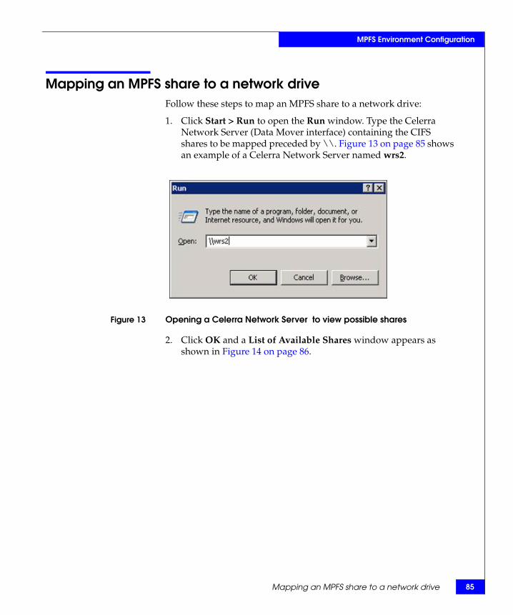
Mapping an MPFS share to a network drive 85
MPFS Environment Configuration
Mapping an MPFS share to a network driveFollow these steps to map an MPFS share to a network drive:
1. Click Start > Run to open the Run window. Type the Celerra Network Server (Data Mover interface) containing the CIFS shares to be mapped preceded by \\. Figure 13 on page 85 shows an example of a Celerra Network Server named wrs2.
Figure 13 Opening a Celerra Network Server to view possible shares
2. Click OK and a List of Available Shares window appears as shown in Figure 14 on page 86.

86 EMC Celerra MPFS over FC and iSCSI v5.0 Windows Clients Product Guide
MPFS Environment Configuration
Figure 14 List of Available Shares
3. Right-click the share to be mapped and select MPFS Volume Properties from the pop-up window as shown in Figure 15 on page 86. The MPFS Properties window is displayed in Figure 16 on page 87.
Figure 15 Selecting the MPFS Volume Properties

Mapping an MPFS share to a network drive 87
MPFS Environment Configuration
4. In the MPFS Properties window, select Enable MPFS to enable MPFS on a share.
Figure 16 MPFS Properties window
5. Optionally, select Persistent Connection to allow the driver to enable MPFS automatically when restarting the system and save the newly specified property values across restarts. If Persistent Connection is not selected, all property values revert to their default values when the server is restarted.
6. Optionally, select any of the share properties below:
• Flush policy — By default, the Windows server writes metadata updates asynchronously. Select Strict Flush Policy to cause the Windows server to flush after every write. Clear Strict Flush Policy to cause asynchronous flushing.
Asynchronous flushing (the default) provides superior performance and is preferable in most situations. Nevertheless, in certain situations use strict (synchronous) flushing. For example, select Strict Flush Policy when two collaborating applications, on two computers, require a high degree of serialization.
When multiple servers access the same MPFS file, their caches may get out of sync.
Use the Strict Flush Policy (synchronous flushing) if problems occur with multi-Windows server sharing.

88 EMC Celerra MPFS over FC and iSCSI v5.0 Windows Clients Product Guide
MPFS Environment Configuration
• Advanced — Click the Advanced button in Figure 16 on page 87 to open the Advanced Option Dialog window as shown in Figure 17 on page 88.
Figure 17 Advanced Option Dialog window
where:
Read ahead — The prefetching of data an application will request so it can be read from the disk drive into its read cache before the data is needed. Read ahead improves the performance of a read operation since the read speed increases if the file is read again. Read ahead is enabled by default.
Write behind — Stores data in a buffer that needs to be written to the disk drive and sends the data when the system is idle or after a certain amount of time has elapsed. This operation optimizes how the disk drive saves data from memory and increases the write speed. When write behind is enabled and the Windows server looses the SAN connection, the data no longer passes through to CIFS. Write behind now issues a new FMP request to synchronize data back to the Data Mover. Write behind is enabled by default.
Section size — The size of the data prefetched for a read ahead or stored for a write behind operation.The default section size is 1 MB.
Async Close Policy — Closes the file before sending data and waiting for an acknowledgement before sending more data. Async Close Policy is disabled by default.
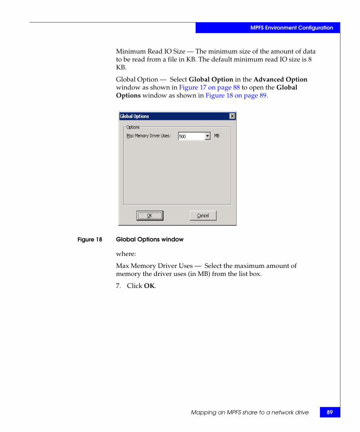
Mapping an MPFS share to a network drive 89
MPFS Environment Configuration
Minimum Read IO Size — The minimum size of the amount of data to be read from a file in KB. The default minimum read IO size is 8 KB.
Global Option — Select Global Option in the Advanced Option window as shown in Figure 17 on page 88 to open the Global Options window as shown in Figure 18 on page 89.
Figure 18 Global Options window
where:
Max Memory Driver Uses — Select the maximum amount of memory the driver uses (in MB) from the list box.
7. Click OK.
90 EMC Celerra MPFS over FC and iSCSI v5.0 Windows Clients Product Guide
MPFS Environment Configuration

Uninstalling or Upgrading MPFS Software 91
3Invisible Body Tag
This chapter describes how to uninstall, upgrade, and disable an active session of the MPFS software.
This chapter covers the following topics:
◆ Uninstalling the MPFS software ...................................................... 92◆ Upgrading the MPFS software......................................................... 95◆ Disabling an active MPFS software session ................................... 97
Uninstalling orUpgrading MPFS
Software
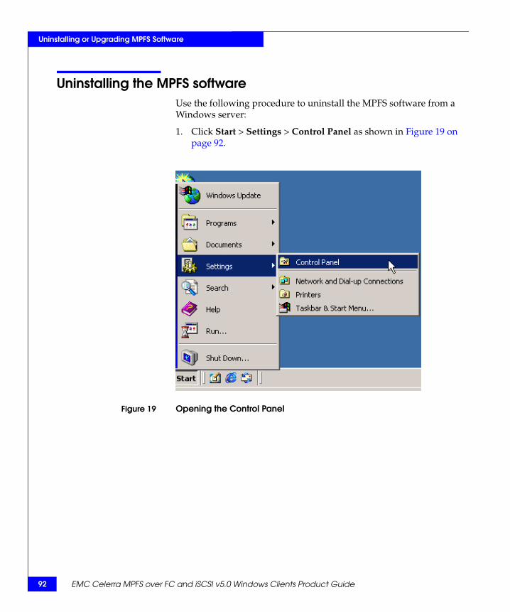
92 EMC Celerra MPFS over FC and iSCSI v5.0 Windows Clients Product Guide
Uninstalling or Upgrading MPFS Software
Uninstalling the MPFS softwareUse the following procedure to uninstall the MPFS software from a Windows server:
1. Click Start > Settings > Control Panel as shown in Figure 19 on page 92.
Figure 19 Opening the Control Panel
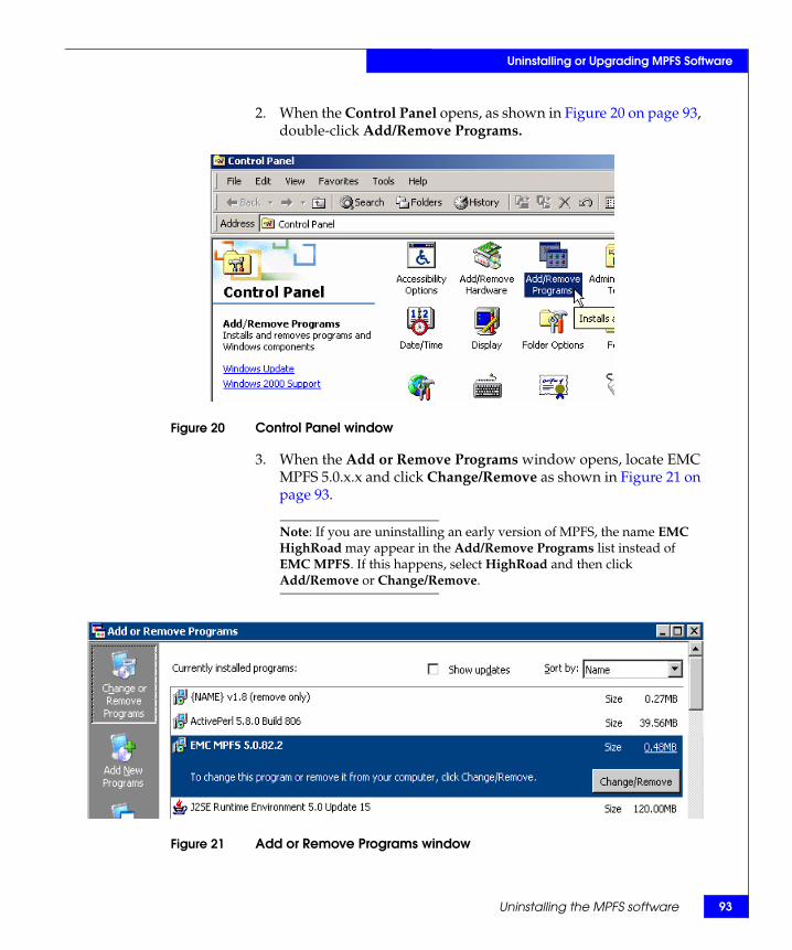
Uninstalling the MPFS software 93
Uninstalling or Upgrading MPFS Software
2. When the Control Panel opens, as shown in Figure 20 on page 93, double-click Add/Remove Programs.
Figure 20 Control Panel window
3. When the Add or Remove Programs window opens, locate EMC MPFS 5.0.x.x and click Change/Remove as shown in Figure 21 on page 93.
Note: If you are uninstalling an early version of MPFS, the name EMC HighRoad may appear in the Add/Remove Programs list instead of EMC MPFS. If this happens, select HighRoad and then click Add/Remove or Change/Remove.
Figure 21 Add or Remove Programs window

94 EMC Celerra MPFS over FC and iSCSI v5.0 Windows Clients Product Guide
Uninstalling or Upgrading MPFS Software
4. Once the MPFS software program has been uninstalled, the Uninstall completed message as shown in Figure 22 on page 94 is displayed.
Figure 22 EMC MPFS Uninstall completed message window
5. Click Yes to restart the Windows server.
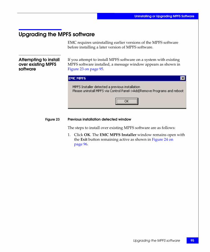
Upgrading the MPFS software 95
Uninstalling or Upgrading MPFS Software
Upgrading the MPFS softwareEMC requires uninstalling earlier versions of the MPFS software before installing a later version of MPFS software.
Attempting to install over existing MPFS software
If you attempt to install MPFS software on a system with existing MPFS software installed, a message window appears as shown in Figure 23 on page 95.
Figure 23 Previous installation detected window
The steps to install over existing MPFS software are as follows:
1. Click OK. The EMC MPFS Installer window remains open with the Exit button remaining active as shown in Figure 24 on page 96.

96 EMC Celerra MPFS over FC and iSCSI v5.0 Windows Clients Product Guide
Uninstalling or Upgrading MPFS Software
2. Click Exit.
Figure 24 EMC MPFS Installer window with Exit button active
3. Remove the existing MPFS software as described in “Uninstalling the MPFS software” on page 92. Then, restart the Windows server before attempting to install new MPFS software.
Installing a later version of MPFS software
To install a later version of MPFS software:
1. Uninstall the previous version of MPFS software as described in “Uninstalling the MPFS software” on page 92.
2. Install the new version of MPFS software as described in “Installing the MPFS software” on page 68.
Each of these steps includes an MPFS software restart as part of the procedure. Restarting is very important, so be sure to perform this step when instructed to do so.
Note: If upgrading from Fibre Channel to iSCSI, complete the environmental changes prior to installing the new MPFS software.

Disabling an active MPFS software session 97
Uninstalling or Upgrading MPFS Software
Disabling an active MPFS software sessionTo disable an active MPFS software session:
1. From My Computer, double-click the Celerra Network Server, and then right-click the share name.
2. Select MPFS Volume Properties from the menu.
The MPFS Properties window opens as shown in Figure 25 on page 97.
Figure 25 MPFS Properties window
3. Clear Enable MPFS and then click OK.

98 EMC Celerra MPFS over FC and iSCSI v5.0 Windows Clients Product Guide
Uninstalling or Upgrading MPFS Software

MPFS Command Line Interface 99
4Invisible Body Tag
This chapter describes the mpfs and mpfsctl commands, which are used on a Windows server to establish and terminate MPFS sessions and to set and display MPFS share properties. Topics covered are:
◆ Overview of the command line interface ..................................... 100◆ mpfscopy........................................................................................... 101◆ mpfsctl -? ........................................................................................... 103◆ mpfsctl config ................................................................................... 104◆ mpfsctl disable.................................................................................. 105◆ mpfsctl diskspeed ............................................................................ 106◆ mpfsctl enable................................................................................... 107◆ mpfsctl inq......................................................................................... 109◆ mpfsctl list ......................................................................................... 110◆ mpfsctl reset ....................................................................................... 111◆ mpfsctl stats ...................................................................................... 112◆ mpfsctl version ................................................................................. 114◆ mpfsinfo............................................................................................. 115◆ mpfsinq.............................................................................................. 116
Note: As an alternative to the command line interface, establish and terminate sessions and set MPFS share properties using the share’s Properties dialog box as described in Chapter 2, ”MPFS Environment Configuration.”
MPFS Command LineInterface
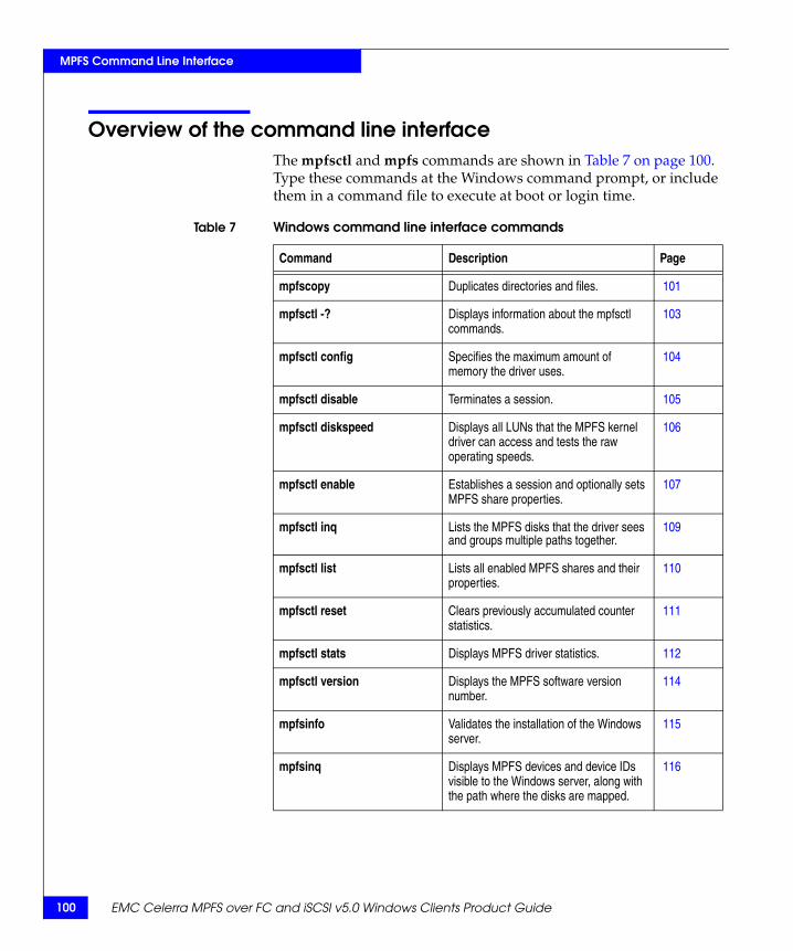
100 EMC Celerra MPFS over FC and iSCSI v5.0 Windows Clients Product Guide
MPFS Command Line Interface
Overview of the command line interfaceThe mpfsctl and mpfs commands are shown in Table 7 on page 100. Type these commands at the Windows command prompt, or include them in a command file to execute at boot or login time.
Table 7 Windows command line interface commands
Command Description Page
mpfscopy Duplicates directories and files. 101
mpfsctl -? Displays information about the mpfsctl commands.
103
mpfsctl config Specifies the maximum amount of memory the driver uses.
104
mpfsctl disable Terminates a session. 105
mpfsctl diskspeed Displays all LUNs that the MPFS kernel driver can access and tests the raw operating speeds.
106
mpfsctl enable Establishes a session and optionally sets MPFS share properties.
107
mpfsctl inq Lists the MPFS disks that the driver sees and groups multiple paths together.
109
mpfsctl list Lists all enabled MPFS shares and their properties.
110
mpfsctl reset Clears previously accumulated counter statistics.
111
mpfsctl stats Displays MPFS driver statistics. 112
mpfsctl version Displays the MPFS software version number.
114
mpfsinfo Validates the installation of the Windows server.
115
mpfsinq Displays MPFS devices and device IDs visible to the Windows server, along with the path where the disks are mapped.
116

mpfscopy 101
MPFS Command Line Interface
mpfscopyThe mpfscopy command is a tool used to duplicate source directories and files to multiple targets specified in the command line. This command uses multiple threads to perform large I/O operations to utilize the I/O characteristics of MPFS.
The mpfscopy command also acts as a test program to perform I/O operations and measure the total throughput of the file systems.
Syntax mpfscopy [-i ii] [-t tt] [-r] [-v] [-h] SOURCE DEST1 DEST2 ...
mpfscopy [-test type] [-i ii] [-s ss] [-v] [-h] FILE1 FILE2 ...
where:
-i ii specifies the size of each I/O operation. If not specified, the default is 1 MB. The size must align to 8K.
-t tt specifies the number of worker threads. If not specified, the default is eight threads.
-r copies the directories in order as specified.
-v run in verbose mode printing out additional information.
-h prints out the help information.
SOURCE specifies the source files or directories to be copied. This option accepts the wild card "*" designator.
DEST1 DEST2 specifies the destination where the source files or directories will be copied. Multiple destinations can be specified.
-test type indicates a test will be performed.
-s ss specifies the size of the files in MB. This option is only used for the write test. If not specified, the default is 1 GB.
FILE1 FILE2 specifies the files used for testing.

102 EMC Celerra MPFS over FC and iSCSI v5.0 Windows Clients Product Guide
MPFS Command Line Interface
Example 1 Copy a single file named mpfscopy.exe to the root directory of the D: drive:
mpfscopy mpfscopy.exe d:\Enumerating files...Start...
Done.
Elapsed time 0.168069 s Average throughput 1.162098 M/s
Example 2 Copy all the files and directories starting with "m" to drive G: and enable the verbose mode. The program will print out the filename of each file it is about to copy:
mpfscopy -r -v m* g:\Enumerating files...Start...mpfscopy.exempfsinfo.exeMSDOS.SYS
Done.
Elapsed time 0.355408 sAverage throughput 0.645715 M/s
Example 3 Start a write test with a 128 MB file and 1 MB of I/O:
mpfscopy -test w -i 1048576 -s 128 g:\test_file.tmp Generating file list... Start...
Done.
Elapsed time 4.343671 s Average throughput 29.468161 M/s
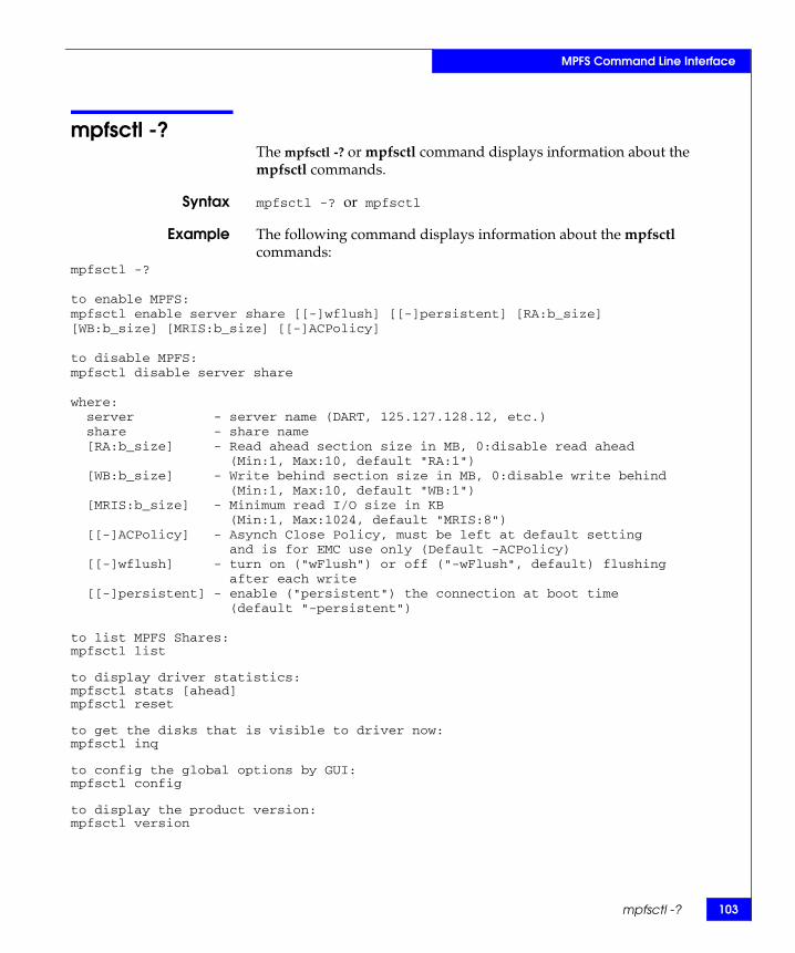
mpfsctl -? 103
MPFS Command Line Interface
mpfsctl -?The mpfsctl -? or mpfsctl command displays information about the mpfsctl commands.
Syntax mpfsctl -? or mpfsctl
Example The following command displays information about the mpfsctl commands:
mpfsctl -?
to enable MPFS: mpfsctl enable server share [[-]wflush] [[-]persistent] [RA:b_size][WB:b_size] [MRIS:b_size] [[-]ACPolicy]
to disable MPFS: mpfsctl disable server share
where:server - server name (DART, 125.127.128.12, etc.)share - share name[RA:b_size] - Read ahead section size in MB, 0:disable read ahead
(Min:1, Max:10, default "RA:1")[WB:b_size] - Write behind section size in MB, 0:disable write behind
(Min:1, Max:10, default "WB:1")[MRIS:b_size] - Minimum read I/O size in KB
(Min:1, Max:1024, default "MRIS:8")[[-]ACPolicy] - Asynch Close Policy, must be left at default setting
and is for EMC use only (Default -ACPolicy)[[-]wflush] - turn on ("wFlush") or off ("-wFlush", default) flushing
after each write[[-]persistent] - enable ("persistent") the connection at boot time
(default "-persistent")
to list MPFS Shares:mpfsctl list
to display driver statistics:mpfsctl stats [ahead]mpfsctl reset
to get the disks that is visible to driver now:mpfsctl inq
to config the global options by GUI:mpfsctl config
to display the product version:mpfsctl version

104 EMC Celerra MPFS over FC and iSCSI v5.0 Windows Clients Product Guide
MPFS Command Line Interface
mpfsctl configThe mpfsctl config command opens the Global Options window as shown in Figure 26 on page 104.
Syntax mpfsctl config
Example
Figure 26 Global Options window
where:
Max Memory Driver Uses: — Select the maximum amount of memory the driver uses (in MB) from the list box. Click OK to close the Global Options window.

mpfsctl disable 105
MPFS Command Line Interface
mpfsctl disableThe mpfsctl disable command terminates a session.
Syntax mpfsctl disable <server> <share>
where:
<server> = MPFS Celerra Network Server<share> = MPFS share on <server>
Example The following command terminates the session on the MPFS share named c2s3fs5 on the server named c2s3e0:
mpfsctl disable c2s3e0 c2s3fs5Request executed.

106 EMC Celerra MPFS over FC and iSCSI v5.0 Windows Clients Product Guide
MPFS Command Line Interface
mpfsctl diskspeedThe mpfsctl diskspeed command displays all LUNs that the mpfs kernel driver can access and tests the raw operating speeds.
Syntax mpfsctl diskspeed
Example The following command tested three out of three LUNs and displays their raw operating speeds:
mpfsctl diskspeed
MPFS kernel driver tested 3 out of 3 LUNs:0001874307271FA0-0003: 25 MB/s0001874307271FA0-0004: 23 MB/s0001874307271FA0-0005: 23 MB/s
Request executed.
mpfsctl enable 107
MPFS Command Line Interface
mpfsctl enableThe mpfsctl enable command establishes a session and optionally, sets properties on an MPFS share.
Syntax mpfsctl enable <server> <share> [[-]wflush] [[-]persistent] [RA:b_size] [WB:b_size] [MRIS:b_size] [[-]ACPolicy]
where:
<server> = MPFS Celerra Network Server <share> = MPFS share on <server>
[wflush] specifies synchronous flushing where the Windows server flushes metadata updates to the Celerra Network Server after every write.
[-wflush] specifies asynchronous flushing which provides superior performance, is preferable in most situations and is the default. However, in certain situations you may want to specify synchronous flushing. For example, specify synchronous flushing when two collaborating applications on two computers require a high degree of serialization.
[persistent] specifies that the connection to the server be retained across restarts.
[-persistent] specifies that the connection be terminated when the server is restarted. This is the default.
[RA: b_size] prefetches data an application will request to improve read operation performance.
[WB: b_size] stores data in a buffer that needs to be written to a disk drive and sends the data when the system is idle to improve the write speed.
[MRIS: b_size] is the minimum size of the amount of data that can be read from a file.
[-ACPolicy] closes the file before sending data and waits for an acknowledgement before sending more data.

108 EMC Celerra MPFS over FC and iSCSI v5.0 Windows Clients Product Guide
MPFS Command Line Interface
Example The following command establishes a session on the MPFS share named 12.345.6.78 on the server named s2_sh1, with synchronous flushing:
mpfsctl enable 12.345.6.78 s2_sh1 wflushRequest executed.

mpfsctl inq 109
MPFS Command Line Interface
mpfsctl inqThe mpfsctl inq command lists the MPFS disks visible to the driver and groups multiple paths together.
Syntax mpfsctl inq
Example The following command lists the MPFS disks that the driver sees and groups multiple paths together:
mpfsctl inq
WWN Celerra Signature60:06:01:60:2e:9b:1e:00:54:81:38:a4:bc:62:dc:11 HK1908073200170000-001760:06:01:60:2e:9b:1e:00:1a:47:c2:e9:a7:62:dc:11 HK1908073200170000-000860:06:01:60:1d:84:1e:00:52:c4:d4:ef:a7:62:dc:11 HK1908073200170000-001860:06:01:60:2e:9b:1e:00:3e:06:ec:f5:a7:62:dc:11 HK1908073200170000-000960:06:01:60:1d:84:1e:00:0e:fa:f4:fb:a7:62:dc:11 HK1908073200170000-001960:06:01:60:2e:9b:1e:00:a0:d9:09:02:a8:62:dc:11 HK1908073200170000-001060:06:01:60:1d:84:1e:00:40:e0:25:08:a8:62:dc:11 HK1908073200170000-002060:06:01:60:2e:9b:1e:00:10:d4:2e:0e:a8:62:dc:11 HK1908073200170000-001160:06:01:60:1d:84:1e:00:b0:da:4a:14:a8:62:dc:11 HK1908073200170000-002160:06:01:60:2e:9b:1e:00:d4:f3:d6:22:a8:62:dc:11 HK1908073200170000-001260:06:01:60:1d:84:1e:00:b2:0e:e7:28:a8:62:dc:11 HK1908073200170000-002260:06:01:60:2e:9b:1e:00:62:73:62:2f:a8:62:dc:11 HK1908073200170000-001360:06:01:60:1d:84:1e:00:a2:9f:a4:35:a8:62:dc:11 HK1908073200170000-002360:06:01:60:2e:9b:1e:00:42:a6:c0:3b:a8:62:dc:11 HK1908073200170000-001460:06:01:60:1d:84:1e:00:c6:5e:ce:41:a8:62:dc:11 HK1908073200170000-002460:06:01:60:2e:9b:1e:00:0c:03:e8:47:a8:62:dc:11 HK1908073200170000-001560:06:01:60:1d:84:1e:00:36:59:f3:4d:a8:62:dc:11 HK1908073200170000-002560:06:01:60:2e:9b:1e:00:54:bf:4f:54:a8:62:dc:11 HK1908073200170000-001660:06:01:60:1d:84:1e:00:12:4b:d2:5a:a8:62:dc:11 HK1908073200170000-0026

110 EMC Celerra MPFS over FC and iSCSI v5.0 Windows Clients Product Guide
MPFS Command Line Interface
mpfsctl listThe mpfsctl list command lists enabled MPFS shares and their properties.
The command displays the following information about each share:
◆ Server name
◆ Share name
◆ Minimal read IO size in KB
◆ Read ahead section size in MB
◆ Write behind section size in MB
◆ Flag settings for flush after every write (wflush is on or -wflush is off)
Syntax mpfsctl list
Example The following example shows an MPFS share enabled on server g10dvt17s601:
mpfsctl list...MPFS Share...
Server: g10dvt17s601, Share: svr6sh1Minimal read IO size: 8KBRead ahead section size: 1MB.Write behind section size: 1 MB.Flags: -wflushValid MPFS connection mapped to 2 disks=== End of List ===

mpfsctl reset 111
MPFS Command Line Interface
mpfsctl resetThe mpfsctl reset command clears previously accumulated counter statistics. Use the mpfsctl reset command to reset the counters to 0 before executing mpfsctl stats.
Syntax mpfsctl reset
Example The following command resets all statistic counters to 0:
mpfsctl reset
Request executed.
Output explanation
The output indicates the command was executed.

112 EMC Celerra MPFS over FC and iSCSI v5.0 Windows Clients Product Guide
MPFS Command Line Interface
mpfsctl statsThe mpfsctl stats command displays MPFS driver statistics.
<disk>, an optional argument, causes the display to include statistics on disk response time. To display disk response-time statistics, execute the mpfsctl stats disk command twice:
◆ The first execution of mpfsctl stats disk turns on a collection of disk response-time statistics.
◆ The second execution displays all activity, including disk response time, since the first execution of the mpfsctl stats disk command.
All subsequent executions of mpfsctl stats disk display all activity, including disk response time, since the previous execution of the command.
To turn off collection and display of disk response-time statistics, simply execute the mpfsctl stats command without the optional disk argument.
Syntax mpfsctl stats <disk>
where <disk> specifies collection and display of statistics on disk response time.
Example The following command displays all statistics including disk response-time statistics:
mpfsctl stats
MPFS Statistics since last query: Bytes Written = 15466496 Bytes Read = 0 Last FMP error = 00000000 Number of FMP errors = 0 Number of FMP OKs = 252 Number of FMP Fail Overs to CIFS = 0 Total requests optimized to CIFS = 0 Total requests passed to CIFS = 0

mpfsctl stats 113
MPFS Command Line Interface
Output explanation The output shows the following activity since the last execution of the mpfsctl stats command:
◆ Number of bytes written directly to the storage-system volume from the server using the FMP protocol: 15466496
◆ Number of bytes read directly from the storage-system volume to the server using the FMP protocol: 0
◆ Hexadecimal error code of the most recent FMP error: 00000000
◆ Total number of FMP errors: 0
◆ Total number of successfully completed I/O operations going directly to and from the disk using the FMP protocol: 252
◆ Total number of attempted FMP operations that failed over to CIFS: 0
◆ Total number of I/O requests optimized to CIFS: 0
◆ Total number of I/O requests passed to CIFS: 0
114 EMC Celerra MPFS over FC and iSCSI v5.0 Windows Clients Product Guide
MPFS Command Line Interface
mpfsctl versionThe mpfsctl version command displays the MPFS software version number.
Syntax mpfsctl version
Example The following command shows which version of the MPFS software is installed on the server:
mpfsctl version
5.0.82
Output explanation
The output displays the MPFS software version number.

mpfsinfo 115
MPFS Command Line Interface
mpfsinfoUse the mpfsinfo command to validate an Windows server installation by querying an FMP server (Celerra Data Mover) and validating that the Windows server can access all the disks required to use MPFS for each exported file system.
The user must have CIFS authorization to the server using the NETBIOS command net use \\server\share (net use /? contains help on the command) for the mpfsinfo.exe command to access the list of shares used by the server.
The user must supply the name or IP address of at least one FMP server. Multiple FMP servers may be specified, in which case the validation is done for the exported file systems on all the listed servers.
Syntax mpfsinfo [-v] <fmpserver>
where:
-v run in verbose mode printing out additional information.
<fmpserver> is the MPFS Celerra Data Mover.
Example The following command shows how to examine Data Mover qua90020:
# mpfsinfo -v qua90020
Output: qua90020 : S2_sh1 - OK APM000522050550000-0014 : OK APM000522050550000-0013 : OK APM000522050550000-0010 : OK APM000522050550000-0009 : OKqua90020 : S2_Sh_N - OK APM000522050550000-0020 : OK APM000522050550000-0019 : OKqua90020 : S2_sh3 - OK APM000522050550000-0014 : OK APM000522050550000-0013 : OK APM000522050550000-0010 : OK APM000522050550000-0009 : OKqua90020 : s2share_v - OK APM000522050550000-0020 : OK APM000522050550000-0019 : OK
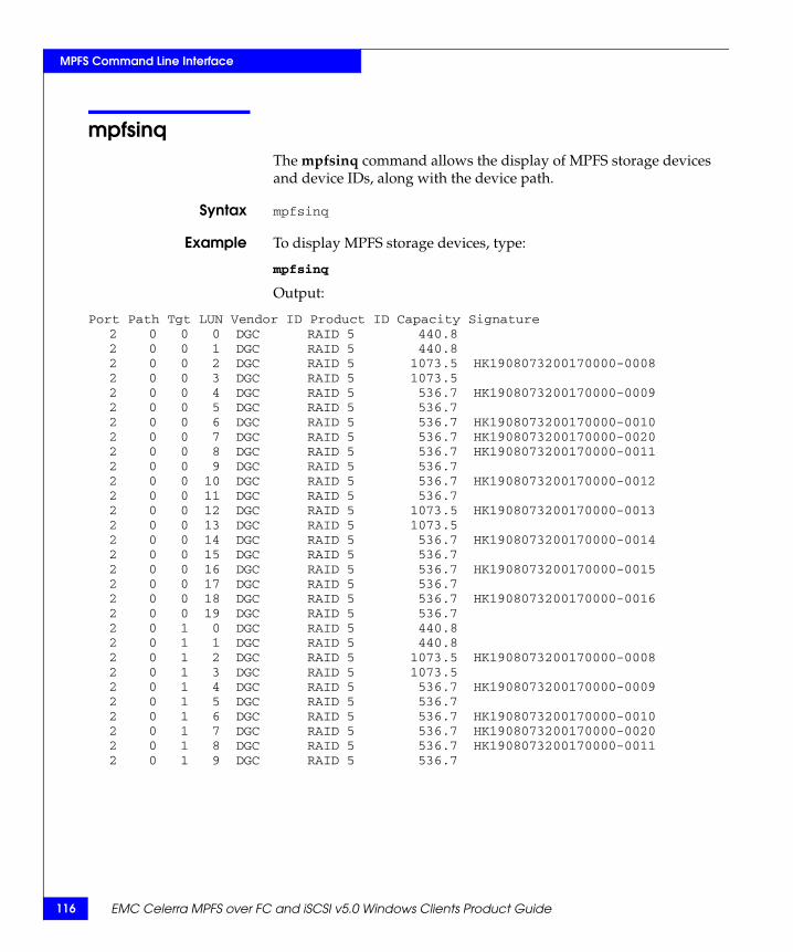
116 EMC Celerra MPFS over FC and iSCSI v5.0 Windows Clients Product Guide
MPFS Command Line Interface
mpfsinqThe mpfsinq command allows the display of MPFS storage devices and device IDs, along with the device path.
Syntax mpfsinq
Example To display MPFS storage devices, type:
mpfsinq
Output:
Port Path Tgt LUN Vendor ID Product ID Capacity Signature2 0 0 0 DGC RAID 5 440.82 0 0 1 DGC RAID 5 440.82 0 0 2 DGC RAID 5 1073.5 HK1908073200170000-00082 0 0 3 DGC RAID 5 1073.52 0 0 4 DGC RAID 5 536.7 HK1908073200170000-00092 0 0 5 DGC RAID 5 536.72 0 0 6 DGC RAID 5 536.7 HK1908073200170000-00102 0 0 7 DGC RAID 5 536.7 HK1908073200170000-00202 0 0 8 DGC RAID 5 536.7 HK1908073200170000-00112 0 0 9 DGC RAID 5 536.72 0 0 10 DGC RAID 5 536.7 HK1908073200170000-00122 0 0 11 DGC RAID 5 536.72 0 0 12 DGC RAID 5 1073.5 HK1908073200170000-00132 0 0 13 DGC RAID 5 1073.52 0 0 14 DGC RAID 5 536.7 HK1908073200170000-00142 0 0 15 DGC RAID 5 536.72 0 0 16 DGC RAID 5 536.7 HK1908073200170000-00152 0 0 17 DGC RAID 5 536.72 0 0 18 DGC RAID 5 536.7 HK1908073200170000-00162 0 0 19 DGC RAID 5 536.72 0 1 0 DGC RAID 5 440.82 0 1 1 DGC RAID 5 440.82 0 1 2 DGC RAID 5 1073.5 HK1908073200170000-00082 0 1 3 DGC RAID 5 1073.52 0 1 4 DGC RAID 5 536.7 HK1908073200170000-00092 0 1 5 DGC RAID 5 536.72 0 1 6 DGC RAID 5 536.7 HK1908073200170000-00102 0 1 7 DGC RAID 5 536.7 HK1908073200170000-00202 0 1 8 DGC RAID 5 536.7 HK1908073200170000-00112 0 1 9 DGC RAID 5 536.7

Error Messages and Troubleshooting 117
AInvisible Body Tag
This appendix describes Windows server error messages, informational messages, and references to troubleshooting documentation. This chapter includes the following topics:
◆ MPFS messages sent to the event log............................................ 118◆ Messages displayed in error message boxes................................ 119◆ Using Windows Event Viewer with MPFS................................... 120◆ Troubleshooting MPFS software.................................................... 125
Error Messages andTroubleshooting
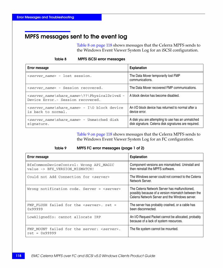
118 EMC Celerra MPFS over FC and iSCSI v5.0 Windows Clients Product Guide
Error Messages and Troubleshooting
MPFS messages sent to the event logTable 8 on page 118 shows messages that the Celerra MPFS sends to the Windows Event Viewer System Log for an iSCSI configuration.
Table 9 on page 118 shows messages that the Celerra MPFS sends to the Windows Event Viewer System Log for an FC configuration.
Table 8 MPFS iSCSI error messages
Error message Explanation
<server_name> - lost session. The Data Mover temporarily lost FMP communications.
<server_name> - Session recovered. The Data Mover recovered FMP communications.
<server_name\share_name>\??\PhysicalDriveX - Device Error.- Session recovered.
A block device has become disabled.
<server_name\share_name> - I\O block device is back to normal.
An I/O block device has returned to normal after a device error.
<server_name\share_name> - Unmatched disk signature.
A disk you are attempting to use has an unmatched disk signature. Celerra disk signatures are required.
Table 9 MPFS FC error messages (page 1 of 2)
Error message Explanation
BfxCommonDeviceControl: Wrong API_MAGIC value -> BFX_VERSION_MISMATCH!
Component versions are mismatched. Uninstall and then reinstall the MPFS software.
Could not Add Connection for <server> The Windows server could not connect to the Celerra Network Server.
Wrong notification code. Server = <server> The Celerra Network Server has malfunctioned, possibly because of a version mismatch between the Celerra Network Server and the Windows server.
FMP_FLUSH failed for the <server>. ret = 0x99999
The server has probably crashed, or a cable has been disconnected.
LowAlignedIo: cannot allocate IRP An I/O Request Packet cannot be allocated, probably because of a lack of system resources.
FMP_MOUNT failed for the server: <server>. ret = 0x99999
The file system cannot be mounted.

Messages displayed in error message boxes 119
Error Messages and Troubleshooting
“Using Windows Event Viewer with MPFS” on page 120 explains how to view these error messages within the Windows environment.
Messages displayed in error message boxesTable 10 on page 119 shows messages the MPFS file system displays in standard error message boxes.
SessionCleanUpApc for the server: <server>. CreateSession failed.
An attempt to reconnect to the server has failed.
SessionCleanUpApc for the server: <server>. Session created.
An attempt to reconnect to the server has succeeded.
Unable to match disk signatures. The Windows server was unable to locate or see one or more Celerra disks. The mpfsctl enable command fails.
Table 9 MPFS FC error messages (page 2 of 2)
Error message Explanation
Table 10 Windows messages displayed in message boxes
Error message Explanation
An incorrect version of WINSOCK.DLL has been found. Network operations may not operate correctly.
MPFS has found and loaded an out-of-date version of WINSOCK.DLL, a file used for initializing communication with the MPFS driver.
Windows sockets initialization failed. Windows socket initialization failed. MPFS could not load or initialize WINSOCK.DLL.
An error occurred while attempting to initialize the MPFS driver.
MPFS could not initialize the MPFS driver. The driver is not running.
120 EMC Celerra MPFS over FC and iSCSI v5.0 Windows Clients Product Guide
Error Messages and Troubleshooting
Using Windows Event Viewer with MPFSThe Windows Event Viewer System Log contains three System Log types: Warning, Error, and Information.
Log type: Warning A Warning log type may be caused by multiple issues. A few examples are:
◆ A network connection may have temporarily been lost.
◆ A Celerra Network Server experienced an error attempting to validate a Windows server's computer account.
◆ The Windows Time Service was not able to find a domain controller.
Log type: Error Examples of Error log type messages are described in Table 8 on page 118 and Table 9 on page 118.
Note: Error messages described are MPFS specific. Other Windows specific error messages may be displayed, some of which are shown in Table 10 on page 119.
Log type: Information
An Information log type may describe several kinds of events. Figure 31 on page 124 shows an example of an informational event.
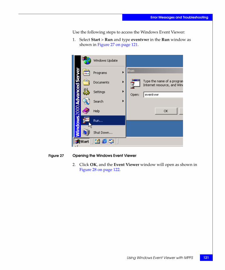
Using Windows Event Viewer with MPFS 121
Error Messages and Troubleshooting
Use the following steps to access the Windows Event Viewer:
1. Select Start > Run and type eventvwr in the Run window as shown in Figure 27 on page 121.
Figure 27 Opening the Windows Event Viewer
2. Click OK, and the Event Viewer window will open as shown in Figure 28 on page 122.

122 EMC Celerra MPFS over FC and iSCSI v5.0 Windows Clients Product Guide
Error Messages and Troubleshooting
Figure 28 Event Viewer window
3. To view an error in the System Log, double-click one of the Error icons listed under the Type column as shown in Figure 29 on page 122.
Figure 29 Selecting an Error message

Using Windows Event Viewer with MPFS 123
Error Messages and Troubleshooting
4. The Event Properties window opens and the selected error appears as shown in Figure 30 on page 123.
Figure 30 Event Properties window
Note: The sequence k2seqa31s8 in Figure 30 on page 123 is an example of a Celerra Network Server name. Server names will be different at each site.
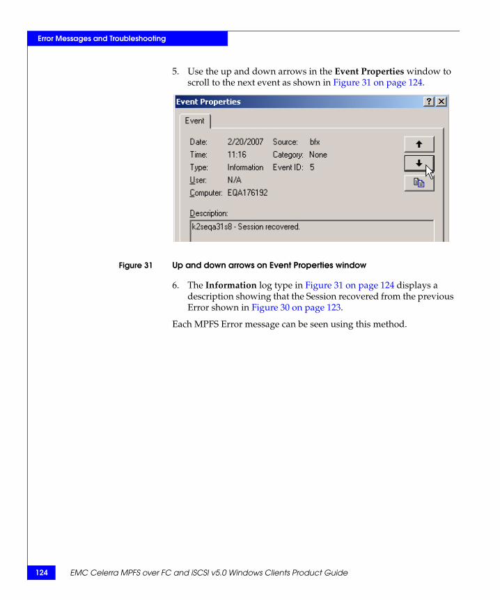
124 EMC Celerra MPFS over FC and iSCSI v5.0 Windows Clients Product Guide
Error Messages and Troubleshooting
5. Use the up and down arrows in the Event Properties window to scroll to the next event as shown in Figure 31 on page 124.
Figure 31 Up and down arrows on Event Properties window
6. The Information log type in Figure 31 on page 124 displays a description showing that the Session recovered from the previous Error shown in Figure 30 on page 123.
Each MPFS Error message can be seen using this method.

Troubleshooting MPFS software 125
Error Messages and Troubleshooting
Troubleshooting MPFS softwareThis section lists procedures, problems, causes, and solutions in troubleshooting the MPFS software.
Refer to the EMC Celerra MPFS for Windows Clients Release Notes for additional information on troubleshooting, known problems, and limitations.
Confirming MPFS software installation
After installing the MPFS software, verify that the software was loaded correctly:
1. Type mpfsctl version in the Command Prompt window to confirm that the MPFS software is properly installed as shown in Figure 32 on page 125.
Figure 32 Using mpfsctl version to verify MPFS software is installed
If the MPFS version number shown in Figure 32 on page 125 matches the version installed, the MPFS software was installed correctly.
2. If a message stating that the MPFS software is not installed appears, select Start > Settings > Control Panel and double-click Add or Remove Programs.
3. Uninstall the MPFS software.
4. Restart the Windows server.
5. Install the MPFS software.
6. Restart the Windows server.
7. Check the MPFS software version.

126 EMC Celerra MPFS over FC and iSCSI v5.0 Windows Clients Product Guide
Error Messages and Troubleshooting
Installing difficulties You may encounter the following problem during installation of the MPFS software.
Problem During installation, a message is displayed indicating you do not have proper access to install the service.
CauseYou lack administrative rights on the server on which you are installing the MPFS software.
SolutionLog in to the server with an administrative account and start the installation again.
Uninstalling difficulties
You may encounter the following problem during removal of the MPFS software.
Problem Locked files remain on the server after uninstalling the MPFS software.
CauseYou failed to restart the server after you uninstalled the MPFS software.
SolutionRestart the server and the locked files are removed.

Connecting CLARiiON CX3-40C iSCSI Cables 127
BInvisible Body Tag
After the components are installed in a cabinet and cabled, the next step is to connect the iSCSI ports on the CLARiiON CX3-40C-based storage array. If the cables are already connected, verify that they are connected properly and all of the connectors are fully seated. This appendix includes the following topic:
◆ iSCSI cabling ..................................................................................... 128
Connecting CLARiiONCX3-40C iSCSI Cables

128 EMC Celerra MPFS over FC and iSCSI v5.0 Windows Clients Product Guide
Connecting CLARiiON CX3-40C iSCSI Cables
iSCSI cablingThe CLARiiON CX3-40C has four 10/100 gigabit Ethernet ports (RJ45 connectors) for iSCSI I/O to a network switch or server NIC or HBA:
1. Before configuring the ports, record the network information for the ports in Table 11 on page 128.
2. Connect up to four copper Ethernet cables from iSCSI ports 0 iSCSI through 3 iSCSI, as shown in Figure 33 on page 129, on each SP to the iSCSI network.
Table 11 CLARiiON SP iSCSI IP addresses
Port IP Netmask Gateway
0 iSCSI (SP A)
_____ . _____ . _____ . _____ _____ . _____ . _____ . _____ _____ . _____ . _____ . _____
1 iSCSI (SP A)
_____ . _____ . _____ . _____ _____ . _____ . _____ . _____ _____ . _____ . _____ . _____
2 iSCSI (SP A)
_____ . _____ . _____ . _____ _____ . _____ . _____ . _____ _____ . _____ . _____ . _____
3 iSCSI (SP A)
_____ . _____ . _____ . _____ _____ . _____ . _____ . _____ _____ . _____ . _____ . _____
0 iSCSI (SP B)
_____ . _____ . _____ . _____ _____ . _____ . _____ . _____ _____ . _____ . _____ . _____
1 iSCSI (SP B)
_____ . _____ . _____ . _____ _____ . _____ . _____ . _____ _____ . _____ . _____ . _____
2 iSCSI (SP B)
_____ . _____ . _____ . _____ _____ . _____ . _____ . _____ _____ . _____ . _____ . _____
3 iSCSI (SP B)
_____ . _____ . _____ . _____ _____ . _____ . _____ . _____ _____ . _____ . _____ . _____

iSCSI cabling 129
Connecting CLARiiON CX3-40C iSCSI Cables
Figure 33 CLARiiON CX3-40C storage processor ports
+-
BE 0 BE 1 4 Fibre 5 Fibre
0 iSCSI 1 iSCSI 2 iSCSI 3 iSCSI
iSCSI ports
AC cord
EMC3533
Back end Fibre Channel ports
Front end Fibre Channel ports(CX3-40C only)
Power andfault LEDs
Service andSPS ports Management LAN
Service LAN

130 EMC Celerra MPFS over FC and iSCSI v5.0 Windows Clients Product Guide
Connecting CLARiiON CX3-40C iSCSI Cables
EMC Celerra MPFS over FC and iSCSI v5.0 Windows Clients Product Guide 131
Glossary
This glossary defines terms useful for MPFS administrators.
CCelerra MPFS over
iSCSIMulti-Path File System over iSCSI-based clients. MPFS client running an iSCSI initiator works in conjunction with an IP-SAN switch containing an iSCSI to SAN blade. The IP-SAN blade provides one or more iSCSI targets that transfer data to the SAN storage systems. See also Multi-Path File Systems (MPFS).
Celerra NetworkServer
EMC network-attached storage (NAS) product line.
ChallengeHandshake
AuthenticationProtocol (CHAP)
Access control protocol for secure authentication using shared passwords called secrets.
client Front-end device that requests services from a server, often across a network.
command lineinterface (CLI)
Interface for entering commands through the Control Station to perform tasks that include the management and configuration of the database and Data Movers and the monitoring of statistics for the Celerra cabinet components.
Common Internet FileSystem (CIFS)
File-sharing protocol based on the Microsoft Server Message Block (SMB). It allows users to share file systems over the Internet and intranets.

132 EMC Celerra MPFS over FC and iSCSI v5.0 Windows Clients Product Guide
Glossary
Control Station Hardware and software component of the Celerra Network Server that manages the system and provides the user interface to all Celerra components.
Ddaemon UNIX process that runs continuously in the background, but does
nothing until it is activated by another process or triggered by a particular event.
Data Mover In a Celerra Network Server, a cabinet component running its own operating system that retrieves files from a storage device and makes them available to a network client. This is also referred to as a blade. A Data Mover is sometimes internally referred to as DART because DART is the software running on the platform.
disk volume On Celerra systems, a physical storage unit as exported from the storage array. All other volume types are created from disk volumes.
Eextent Set of adjacent physical blocks.
Ffallthrough Fallthrough occurs when MPFS temporarily employs the NFS or CIFS
protocol to provide continuous data availability, reliability, and protection while block I/O path congestion or unavailability is resolved. This fallthrough technology is seamless and transparent to the application being used.
Fast Ethernet Any Ethernet specification with a speed of 100 Mb/s. Based on the IEEE 802.3u specification.
Fibre Channel Nominally 1 Gb/s data transfer interface technology, although the specification allows data transfer rates from 133 Mb/s up to 4.25 Gb/s. Data can be transmitted and received simultaneously. Common transport protocols, such as Internet Protocol (IP) and Small Computer Systems Interface (SCSI), run over Fibre Channel. Consequently, a single connectivity technology can support high-speed I/O and networking.

EMC Celerra MPFS over FC and iSCSI v5.0 Windows Clients Product Guide 133
Glossary
File Mapping Protocol(FMP)
File system protocol used to exchange file layout information between an MPFS client and the Celerra Network Server. See also Multi-Path File Systems (MPFS).
file system Method of cataloging and managing the files and directories on a storage system.
FLARE Embedded operating system in CLARiiON disk arrays.
Ggateway A Celerra network server that is capable of connecting to multiple
storage arrays, either directly (direct-connected) or through a Fibre Channel switch (fabric-connected).
Gigabit Ethernet Any Ethernet specification with a speed of 1000 Mb/s. IEEE 802.3z defines Gigabit Ethernet over fiber and cable, which has a physical media standard of 1000Base-X (1000Base-SX short wave, 1000Base-LX long wave) and 1000Base-CX shielded copper cable. IEEE 802.3ab defines Gigabit Ethernet over an unshielded twisted pair (1000Base-T).
Hhost Addressable end node capable of transmitting and receiving data.
IInternet Protocol (IP) Network layer protocol that is part of the Open Systems
Interconnection (OSI) reference model. IP provides logical addressing and service for end-to-end delivery.
Internet Protocoladdress (IP Address)
Address uniquely identifying a device on any TCP/IP network. Each address consists of four octets (32 bits), represented as decimal numbers separated by periods. An address is made up of a network number, an optional subnetwork number, and a host number.
Internet SCSI (iSCSI) Protocol for sending SCSI packets over TCP/IP networks.
iSCSI initiator iSCSI endpoint, identified by a unique iSCSI name, which begins an iSCSI session by issuing a command to the other endpoint (the target).

134 EMC Celerra MPFS over FC and iSCSI v5.0 Windows Clients Product Guide
Glossary
iSCSI target iSCSI endpoint, identified by a unique iSCSI name, which executes commands issued by the iSCSI initiator.
Llogical unit (LU) For iSCSI on a Celerra Network Server, a logical unit is an iSCSI
software feature that processes SCSI commands, such as reading from and writing to storage media. From a iSCSI host perspective, a logical unit appears as a disk device.
logical unit number(LUN)
Identifying number of a SCSI or iSCSI object that processes SCSI commands. The LUN is the last part of the SCSI address for a SCSI object. The LUN is an ID for the logical unit, but the term is often used to refer to the logical unit itself.
logical volume Logical devices aggregated and managed at a higher level by a volume manager.
Mmetadata Data containing structural information (such as access methods)
about itself.
metavolume On a Celerra system, a concatenation of volumes, which can consist of disk, slice, or stripe volumes. Also called a hyper volume or hyper. Every file system must be created on top of a unique metavolume.
mirrored pair Logical volume with all data recorded twice, once on each of two different physical devices.
mirroring Method by which the storage system maintains two identical copies of a designated volume on separate disks.
mount Process of attaching a subdirectory of a remote file system to a mount point on the local machine.
mount point Local subdirectory to which a mount operation attaches a subdirectory of a remote file system.
MPFS session Connection between an MPFS client and a Celerra MPFS Network Server.
MPFS share Shared resource designated for multiplexed communications using the MPFS file system.
EMC Celerra MPFS over FC and iSCSI v5.0 Windows Clients Product Guide 135
Glossary
Multi-Path File Systems(MPFS)
Celerra Network Server feature that allows heterogeneous servers with MPFS software to concurrently access, directly over Fibre Channel or iSCSI channels, shared data stored on a Symmetrix or CLARiiON storage array. MPFS adds a lightweight protocol called File Mapping Protocol (FMP) that controls metadata operations.
Nnested mount file
system (NMFS)File system that contains the nested mount root file system and component file systems.
nested mount filesystem root
File system on which the component file systems are mounted read-only except for mount points of the component file systems.
network-attachedstorage (NAS)
Specialized file server that connects to the network. A NAS device, such as Celerra Network Server, contains a specialized operating system and a file system, and processes only I/O requests by supporting popular file sharing protocols such as NFS and CIFS.
network file system(NFS)
Network file system (NFS) is a network file system protocol allowing a user on a client computer to access files over a network as easily as if the network as easily as if the network devices were attached to its local disks.
PPowerPath EMC host-resident software that integrates multiple path I/O
capabilities, automatic load balancing, and path failover functions into one comprehensive package for use on open server platforms connected to Symmetrix or CLARiiON enterprise storage systems.
RRedundant Array ofIndependent Disks
(RAID)
Method for storing information where the data is stored on multiple disk drives to increase performance and storage capacities and to provide redundancy and fault tolerance.
Sserver Device that handles requests made by clients connected through a
network.
136 EMC Celerra MPFS over FC and iSCSI v5.0 Windows Clients Product Guide
Glossary
small computersystem interface
(SCSI)
Standard set of protocols for host computers communicating with attached peripherals.
storage area network(SAN)
Network of data storage disks. In large enterprises, a SAN connects multiple servers to a centralized pool of disk storage. See also network attached storage (NAS).
storage processor (SP) Storage processor on a CLARiiON storage system. On a CLARiiON storage system, a circuit board with memory modules and control logic that manages the storage system I/O between the host’s Fibre Channel adapter and the disk modules.
Storage processor A(SP A)
Generic term for the first storage processor in a CLARiiON storage system.
Storage processor B(SP B)
Generic term for the second storage processor in a CLARiiON storage system.
stripe size Number of blocks in one stripe of a stripe volume.
Symmetrix RemoteData Facility (SRDF)
EMC technology that allows two or more Symmetrix systems to maintain a remote mirror of data in more than one location. The systems can be located within the same facility, in a campus, or hundreds of miles apart using fibre or dedicated high-speed circuits. The SRDF family of replication software offers various levels of high-availability configurations, such as SRDF/Synchronous (SRDF/S) and SRDF/Asynchronous (SRDF/A).
TTransmission Control
Protocol (TCP)Connection-oriented transport protocol that provides reliable data delivery.
Uunified storage A Celerra network server that is connected to a captive storage array
that is not shared with any other Celerra network servers and is not capable of connecting to multiple storage arrays.
VVirtual Storage
Network (VSAN)SAN that can be broken up into sections allowing traffic to be isolated within the section.

EMC Celerra MPFS over FC and iSCSI v5.0 Windows Clients Product Guide 137
AAccess Logix configuration 66adding Fibre Channel hosts to storage groups 74adding initiators to storage groups 83adding storage 67administering MPFS 99architecture
Celerra gateway with Fibre Channel 20, 40Celerra gateway with iSCSI 22, 41Celerra gateway with iSCSI (MDS-based) 23,
42Celerra unified storage with Fibre Channel
19, 40Celerra unified storage with iSCSI 21, 41Celerra unified storage with iSCSI
(MDS-based) 21, 41asynchronous flushing 87, 107authentication, CHAP 78
CCelerra gateway with Fibre Channel 20, 40Celerra gateway with iSCSI 22, 41Celerra gateway with iSCSI (MDS-based) 23, 42Celerra Network Server
configuring 51enabling MPFS 57setup 49
Celerra unified storage with Fibre Channel 19, 40Celerra unified storage with iSCSI 21, 41Celerra unified storage with iSCSI (MDS-based)
21, 41Celerra with MPFS configuration 32
Challenge Handshake Authentication Protocol (CHAP) 35, 78
CLARiiONbased array requirements 47configuring using CLI commands 58CX3-40C iSCSI cables 127iSCSI port configuration 65
command line interface. See mpfs commandscommand line interface. See mpfsctl commandscommands
mpfs copy 101mpfs info 115mpfs inq 116mpfsctl -? 103mpfsctl config 104mpfsctl disable 105mpfsctl diskspeed 106mpfsctl enable 107mpfsctl inq 109mpfsctl list 110mpfsctl reset 111mpfsctl stats 112mpfsctl version 114
comments 15configuration overview 30configuration planning checklist 38configuring
Celerra Network Server 32, 51storage 73storage access 58, 60zones 58, 60
configuring Gigabit Ethernet ports 42connecting to a server 107creating
Index

EMC Celerra MPFS over FC and iSCSI v5.0 Windows Clients Product Guide138
Index
a file system 51a security file 64
creating storage groups 67
Ddata mover capacity 33disabling active MPFS session 97disabling MPFS using mpfsctl disable 105displaying MPFS devices 116
Eenabling MPFS using mpfsctl enable 107enabling SP interfaces 63error messages 117establishing an MPFS session
using mpfsctl enable 107
FFibre Channel
driver installation 73switch installation 59switch requirements 45
File Mapping Protocol (FMP) 28file system
creation 51setup 50
firewall FMP ports 72flush policy, setting
through the Properties dialog box 87using mpfsctl enable 107
GGigabit Ethernet port configuration 42
II/O sizes 32installing
Fibre Channel switch 46MPFS software 70MPFS software, troubleshooting 126storage system 44
IP-SAN switch requirements 46iSCSI CHAP authentication 35iSCSI initiator
configure iSCSI discovery 78configure with CHAP 77configuring 76installing 76log into iSCSI target 80register 77
iSCSI proxy new zone 63iSCSI-to-Fibre Channel bridge configuration 60
MMDS iSCSI port configuration 61mpfs commands
mpfs copy 101mpfs info 115mpfs inq 116
MPFS configuration summary 24MPFS devices, displaying 116MPFS session
retaining properties 107starting
using mpfsctl enable 107stopping
through the Properties dialog box 97using mpfsctl disable 105
MPFS shareconnecting 107disconnecting 105enabling 87properties
listing 110retaining across restarts 87, 107setting 107
MPFS softwareconfirm installation 125disabling active MPFS session 97installation issues 126managing using mpfsctl commands 99uninstalling 92upgrading 95
MPFS threads 32mpfsctl commands
mpfs inq 109mpfsconfig 104mpfsctl -? 103mpfsctl disable 105mpfsctl enable 107

139EMC Celerra MPFS over FC and iSCSI v5.0 Windows Clients Product Guide
Index
mpfsctl list 110mpfsctl reset 111mpfsctl stats 112mpfsctl version 114mpfsdiskspeed 106
Ooverview of configuring MPFS 30
Ppersistent connection 87PowerPath support 32properties
listing 110retaining across restarts 87, 107setting 107
Rread cache requirements 34removing MPFS software, troubleshooting 126reverse authentication 78
Ssecret (CHAP) 78security file creation 64SendTargets discovery 78server, connecting to 107session
authentication 78retaining across restarts 107starting
using mpfsctl enable 107stopping
through the Properties dialog box 97using mpfsctl disable 105
software componentsCelerra Network Server NAS software 43Java Runtime Environment 43MPFS software 43Windows iSCSI Initiator 43
starting an MPFS session
using mpfsctl enable 107statistics, displaying 112stopping an MPFS session
through the Properties dialog box 97using mpfsctl disable 105
storage groupadd Fibre Channel hosts 74configuring 73
storage guidelines 34storage system
configuring 59installation 44requirements 44
synchronous flushing 87, 107system component verification 40
Ttroubleshooting 117
access to install MPFS software 126locked files on server 126MPFS software installation 125
Uuninstalling MPFS software 92uninstalling MPFS, troubleshooting 126upgrading MPFS software 95
Vversion number, displaying 114VMware ESX 36volume stripe size 32
WWindows server
configuration 34, 37installation 68Windows OS versions 69
Zzone activation 59

EMC Celerra MPFS over FC and iSCSI v5.0 Windows Clients Product Guide140
Index