emc compliance tech guide.pdf
TRANSCRIPT

7/27/2019 EMC Compliance Tech Guide.pdf
http://slidepdf.com/reader/full/emc-compliance-tech-guidepdf 1/40
EMC Compliant Installation
and Configuration for a
Power Drive System
Technical Guide No. 3Technical Guide No. 3

7/27/2019 EMC Compliance Tech Guide.pdf
http://slidepdf.com/reader/full/emc-compliance-tech-guidepdf 2/40
Technical Guide No.3 - EMC Compliant Installation & Configuration for a PDS 2

7/27/2019 EMC Compliance Tech Guide.pdf
http://slidepdf.com/reader/full/emc-compliance-tech-guidepdf 3/40
3 Technical Guide No.3 - EMC Compliant Installation & Configuration for a PDS
1 Introduction ..............................................................General .......................................................................This guide’s purpose ...................................................
The Directives concerning drives ...........................Who is the manufacturer? ......................................The responsibility of the manufacturer ...................OEM customer as a manufacturer .........................Panel builder or system integratoras a manufacturer ...................................................Definitions ...............................................................
Practical installations and systems ........................Earthing principles ..................................................Product-specific manuals .......................................
2 Definitions .................................................................Electromagnetic Compatibility (EMC) of PDS ............
Immunity .................................................................Emission .................................................................
Power Drive System ...................................................Types of equipment ....................................................
Component .............................................................
Components with direct function ............................Components without direct function .......................Apparatus & systems .............................................Installation ..............................................................CE marking for EMC ..............................................
Installation environments ............................................First Environment ...................................................Second Environment ..............................................Propagation ............................................................
The drive’s route to market .........................................
Unrestricted distribution.........................................Restricted distribution ............................................
EMC emission limits ..................................................
3 EMC solutions .........................................................General ......................................................................Solutions for EMC compatibility.................................
Emissions ..............................................................Conducted emission ..............................................Radiated emission .................................................
Clean and dirty side ...............................................RFI filtering ............................................................
Contents
5555555
66
667
888889
10
10111111111112121212
131313
15
1515151516
1717

7/27/2019 EMC Compliance Tech Guide.pdf
http://slidepdf.com/reader/full/emc-compliance-tech-guidepdf 4/40
Technical Guide No.3 - EMC Compliant Installation & Configuration for a PDS 4
Selecting the RFI filter ...........................................Installation of the RFI filter ....................................Drives in IT-networks .............................................Arc suppressors.....................................................Selection of a secondary enclosure ......................Holes in enclosures ...............................................HF earthing ............................................................HF earthing with cable glands ...............................HF earthing with conductive sleeve.......................360O earthing at motor end ....................................Conductive gaskets with control cables ................Installation of accessories .....................................Internal wiring ........................................................Control cables and cabling ....................................Power cables .........................................................Transfer impedance ...............................................Use of Ferrite rings ................................................
4 Practical Examples..................................................Simple installation ......................................................Example of By-pass system <100kVA ......................
Typical example of a 12-pulse drive ..........................Example of common DC bus fed sectional drive ......
5 Bibliography ............................................................
6 Index .........................................................................
1818191919212222232424
252627283030
323233
3436
37
38

7/27/2019 EMC Compliance Tech Guide.pdf
http://slidepdf.com/reader/full/emc-compliance-tech-guidepdf 5/40
5 Technical Guide No.3 - EMC Compliant Installation & Configuration for a PDS
This guide assists design and installation personnel whentrying to ensure compliance with the requirements of the EMCDirective in the user’s systems and installations when usingAC drives.
The purpose of this guide is to guide Original EquipmentManufacturers (OEM), system integrators and panelbuildersin designing or installing AC drive products and their auxiliarycomponents into their own installation and systems. Theauxiliaries include contactors, switches, fuses, etc. By followingthese instructions it is possible to fulfil EMC requirementsand give CE marking when necessary.
There are three directives which concern variable speeddrives. They are the Machinery Directive, Low Voltage Directiveand EMC Directive. The requirements and principles of theDirectives and use of CE marking is described in TechnicalGuide No. 2 “EU Council Directives and Variable SpeedDrives”. This document deals only with the EMC Directive.
The European Commission has published guidelines on the
application of the EMC Directive. These guidelines give thefollowing definition of a manufacturer: “This is the personresponsible for the design and construction of an apparatuscovered by the Directive with a view to placing it on the EEAmarket on his own behalf. Whoever modifies substantially anapparatus resulting in an “as-new” apparatus, with a view toplacing it on the EEA market, also becomes the manufacturer.”
According to EMC Directive (89/336/EEC) article 10part 1, the manufacturer is responsible for attaching the CE-mark to each unit. According to part 2 the manufacturer is
responsible for writing and updating the Technical ConstructionFile (TCF), if the TCF route is used.
It is well known that OEM customers sell equipment usingown trade marks or brand labels. Changing the trademark,brand label or the type marking is an example of modificationresulting in “as new” equipment.
Chapter 1 - Introduction
General
This guide’s purpose
The Directives concerning
drives
Who is the manufacturer?
The responsibility of
the manufacturer
OEM customer as a manufacturer

7/27/2019 EMC Compliance Tech Guide.pdf
http://slidepdf.com/reader/full/emc-compliance-tech-guidepdf 6/40
Technical Guide No.3 - EMC Compliant Installation & Configuration for a PDS 6
Definitions
Practical installations and
systems
Earthing principles
Frequency converters sold as OEM products shall beconsidered components (Complete Drive Module CDM orBasic Drive Module BDM). Apparatus is an entity and includes
any documentation (manuals) intended for the final customer.Thus, the OEM-customer has sole and ultimateresponsibility concerning EMC of equipment, and he shallissue a Declaration of Conformity and Technical ConstructionFile for the equipment.
ABB Industry Oy offers services to help OEM customers toissue a TCF and a DoC in order to CE mark the productaccording to the EMC Directive.
According to the EMC Directive, a system is defined as a
combination of several types of equipment, finished products,and/or components combined, designed and/or put togetherby the same person (system manufacturer) intended tobe placed on the market for distribution as a single functionalunit for an end-user and intended to be installed and operatedtogether to perform a specific task.
A panel builder or system integrator typically undertakes thiskind of work. Thus, the panel builder or system integrator hassole and ultimate responsibility concerning EMC of the system.He cannot pass this responsibility to a supplier.
In order to help panel builder/system integrator, ABB IndustryOy offers installation guidelines related to each product aswell as general EMC guidelines (this document).
The EMC Product Standard for Power Drive Systems, EN61800-3 (or IEC 61800-3) is used as the main standard forvariable speed drives. The terms and definitions defined inthe standard are also used in this guide.
This guide gives practical EMC examples and solutions whichare not described in product specific manuals. The solutionscan be directly used or applied by the OEM or panelbuilder.
The earthing and cabling principles of variable speed drivesare described in the manual “Grounding and cabling ofthe drive system”, code 3AFY 61201998. It also includes ashort description of interference phenomena.
Panel builder or
system integrator as a manufacturer
Introduction

7/27/2019 EMC Compliance Tech Guide.pdf
http://slidepdf.com/reader/full/emc-compliance-tech-guidepdf 7/40
7 Technical Guide No.3 - EMC Compliant Installation & Configuration for a PDS
Detailed information on the installation and use of products,cable sizes etc. can be found in the product specific manuals.This guide is intended to be used together with product specific
manuals.
Product-specific manuals
Introduction
7/27/2019 EMC Compliance Tech Guide.pdf
http://slidepdf.com/reader/full/emc-compliance-tech-guidepdf 8/40
Technical Guide No.3 - EMC Compliant Installation & Configuration for a PDS 8
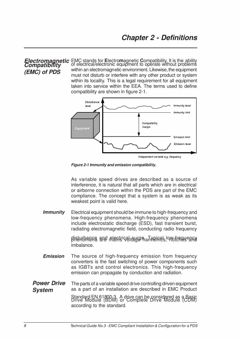
EMC stands for Electromagnetic Compatibility. It is the abilityof electrical/electronic equipment to operate without problemswithin an electromagnetic environment. Likewise, the equipmentmust not disturb or interfere with any other product or systemwithin its locality. This is a legal requirement for all equipmenttaken into service within the EEA. The terms used to definecompatibility are shown in figure 2-1.
As variable speed drives are described as a source ofinterference, it is natural that all parts which are in electricalor airborne connection within the PDS are part of the EMCcompliance. The concept that a system is as weak as itsweakest point is valid here.
Electrical equipment should be immune to high-frequency andlow-frequency phenomena. High-frequency phenomenainclude electrostatic discharge (ESD), fast transient burst,radiating electromagnetic field, conducting radio frequency
disturbance and electrical surge. Typical low-frequencyphenomena are mains voltage harmonics, notches andimbalance.
The source of high-frequency emission from frequencyconverters is the fast switching of power components suchas IGBTs and control electronics. This high-frequencyemission can propagate by conduction and radiation.
The parts of a variable speed drive controlling driven equipmentas a part of an installation are described in EMC Product
Standard EN 61800-3. A drive can be considered as a BasicDrive Module (BDM) or Complete Drive Module (CDM)according to the standard.
Electromagnetic Compatibility (EMC) of PDS
Emission
Chapter 2 - Definitions
Figure 2-1 Immunity and emission compatibility.
Power Drive System
Immunity
7/27/2019 EMC Compliance Tech Guide.pdf
http://slidepdf.com/reader/full/emc-compliance-tech-guidepdf 9/40
9 Technical Guide No.3 - EMC Compliant Installation & Configuration for a PDS
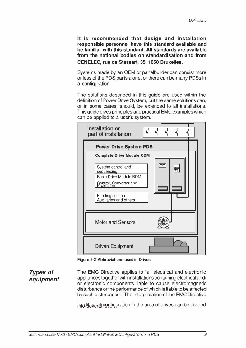
System control andsequencing
Basic Drive Module BDM
Control, Converter andProtection
Feeding sectionAuxiliaries and others
Motor and Sensors
Driven Equipment
It is recommended that design and installationresponsible personnel have this standard available andbe familiar with this standard. All standards are availablefrom the national bodies on standardisation and from
CENELEC, rue de Stassart, 35, 1050 Bruxelles.
Systems made by an OEM or panelbuilder can consist moreor less of the PDS parts alone, or there can be many PDSs ina configuration.
The solutions described in this guide are used within thedefinition of Power Drive System, but the same solutions can,or in some cases, should, be extended to all installations.This guide gives principles and practical EMC examples whichcan be applied to a user’s system.
The EMC Directive applies to “all electrical and electronicappliances together with installations containing electrical and/ or electronic components liable to cause electromagneticdisturbance or the performance of which is liable to be affectedby such disturbance”. The interpretation of the EMC Directive
for different configuration in the area of drives can be dividedinto several levels:
Figure 2-2 Abbreviations used in Drives.
Definitions
Types of equipment
7/27/2019 EMC Compliance Tech Guide.pdf
http://slidepdf.com/reader/full/emc-compliance-tech-guidepdf 10/40
Technical Guide No.3 - EMC Compliant Installation & Configuration for a PDS 10
Component In this context the interpretation of component can be dividedinto two main categories. The component can either deliver a‘direct function’ or not.
Direct function:Any function of the component itself, which fulfils the intended use, specified by the manufacturer in the instruction for use for an end user.
Components with a direct function can be divided into twosub-groups:
1) The direct function is available without further adjustment or connections other than simple ones, which can be
performed by any person not fully aware of the EMC implications. Such a component is an ‘apparatus’ and it is subjected to all provisions of the EMC Directive.
2) The direct function is not available without further adjustment or connections other than simple ones, which can be performed by any person not fully aware of the EMC implications. Such a component is not an ‘apparatus’.The only requirement for such a component is to provide it with instructions for use for the professional assembler or manufacturer of the final apparatus into which the
component will be incorporated. These instructions should help him to solve any EMC problems with his final apparatus.
If a component performs a direct function without furtheradjustment other than simple ones, the component isconsidered equivalent to apparatus (Case 1). Some variablespeed power drive products fall into this category, e.g. a driveinstalled into a cabinet or drive with enclosure and sold as acomplete unit (CDM). All provisions of the EMC Directive apply(CE-mark, Declaration of Conformity).
If a component performs a direct function that is not availablewithout further adjustment other than simple ones, it isconsidered as a component (Case 2). Some variable speedpower drive products fall into this category, e.g. basic drivemodule (BDM). These are meant to be assembled by aprofessional assembler (e.g. panel builder or systemmanufacturer) into a cabinet not in the scope of delivery ofthe manufacturer of the BDM. According to the EMC Directive,the requirement for the BDM supplier is to deliver instructionsfor installation and use.
According to the EMC Directive the system manufacturer orpanel builder is resonsible for CE-mark, Declaration ofConformity and Technical Construction File.
Components with
direct function
Definitions

7/27/2019 EMC Compliance Tech Guide.pdf
http://slidepdf.com/reader/full/emc-compliance-tech-guidepdf 11/40
11Technical Guide No.3 - EMC Compliant Installation & Configuration for a PDS
Components
without direct function
Components with no direct function are not considered asapparatus within the meaning of the EMC Directive. The EMCDirective does not apply to these. These components include
resistors, cables, terminal blocks, etc.
A finished product containing electrical and/or electroniccomponents and intended to be placed on the market and/ortaken into service as a single commercial unit.
Several items of apparatus combined to fulfil a specificobjective and intended to be placed on the market as a singlefunctional unit.
A combination of items of apparatus, equipment and/or
components put together at a given place to fulfil a specificobjective but not intended to be placed on the market as asingle functional unit.
A component with a direct function without further adjustmentthan simple ones needs to carry CE marking for EMC (Case 1).
A component with a direct function that is not available withoutfurther adjustment than simple ones does not need to carryCE marking for EMC (Case 2) .
Note: The products may carry CE marking for other directivesthan EMC.
Apparatus and systems must be CE marked.
Installations are required to satisfy various parts of the Directives,
but are not required to be CE marked.
The PDSs can be connected to either industrial or public powerdistribution networks. The environment class depends onthe way the PDS is connected to power supply. The
environment classes are First and Second Environment.
Apparatus and systems
Installation
CE marking for EMC
Figure 2-3 The CE mark.
Installation environments
Definitions
7/27/2019 EMC Compliance Tech Guide.pdf
http://slidepdf.com/reader/full/emc-compliance-tech-guidepdf 12/40
Technical Guide No.3 - EMC Compliant Installation & Configuration for a PDS 12
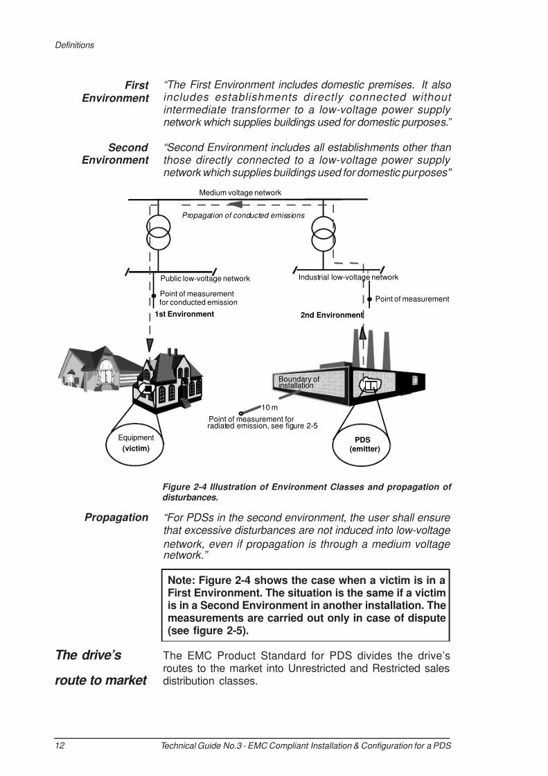
“The First Environment includes domestic premises. It also includes establishments directly connected without intermediate transformer to a low-voltage power supply network which supplies buildings used for domestic purposes.”
“Second Environment includes all establishments other than those directly connected to a low-voltage power supply network which supplies buildings used for domestic purposes"
“For PDSs in the second environment, the user shall ensure that excessive disturbances are not induced into low-voltage
network, even if propagation is through a medium voltage network.”
Note: Figure 2-4 shows the case when a victim is in aFirst Environment. The situation is the same if a victimis in a Second Environment in another installation. Themeasurements are carried out only in case of dispute(see figure 2-5).
The EMC Product Standard for PDS divides the drive’sroutes to the market into Unrestricted and Restricted salesdistribution classes.
First Environment
Second Environment
Figure 2-4 Illustration of Environment Classes and propagation of disturbances.
Definitions
Propagation
The drive’s
route to market
Medium voltage network
PDS
(emitter)
Equipment
(victim)
Point of measurementfor conducted emission
Point of measurement forradiated emission, see figure 2-5
10 m
Public low-voltage network
Boundary ofinstallation
Industrial low-voltage network
2nd Environment
Point of measurement
1st Environment
Propagation of conducted emissions

7/27/2019 EMC Compliance Tech Guide.pdf
http://slidepdf.com/reader/full/emc-compliance-tech-guidepdf 13/40
13 Technical Guide No.3 - EMC Compliant Installation & Configuration for a PDS
“Unrestricted distribution is a mode of sales distribution in which the supply of equipment is not dependent on the EMC competence of the customer or user for the application of drives".
Goods can be placed in service by a person skilled in theoperation of goods, but without any specific EMC experience.
“Restricted distribution is a mode of sales distribution in which the manufacturer restricts the supply of equipment to suppliers,customers or users who separately or jointly have technical competence in the EMC requirements of the application of
drives.”
This means that the goods require EMC competence to beput into service.
The EMC emission limits for PDS depend on the installationenvironment, type of power supply network and power of thedrive. Limits for certain conditions can be selected by usingthe following flow chart (see Figure 2-5).
Restricted distribution
EMC emission limits
Unrestricted distribution
Definitions

7/27/2019 EMC Compliance Tech Guide.pdf
http://slidepdf.com/reader/full/emc-compliance-tech-guidepdf 14/40
Technical Guide No.3 - EMC Compliant Installation & Configuration for a PDS 14
EN 61800-3EMC Product Standard for PDS
1st Environment(public low-voltage network)
Low Power1<25A
Medium Power1>25A
2nd Environment(industrial network)
Either Unrestrictedor Restricted distr.
No differenceby power
LIMITS UNDER CONSIDERATIONNote! In case of dispute, outside the boundary
of installation, limits for propagated disturbance
are as in opposite chart:
, if “outside” is in 1st environment
, if “outside” is in 2nd environment
CONDUCTED
RADIATED
In case of dispute, outside the boundary ofinstallation, limits for propagated disturbanceare as in opposite chart. In-situ measurementsshall be made outside the building where PDSis situated.
DISPUTEThe polluter solves
Disturbancein power portdBuV100
79736656
80
60
40
20
0
0.15 0.5 1 5 10 30 0.15 0.5 1 5 10 30
50
45
40
35
30
25
47
37
>25A (10 m)
<25A (10 m)
30 230
0 200 400 600 800 1000 0 200 400 600 800 1000
Frequency (MHz) Frequency (MHz)
DisturbancedBuV/m
Frequency (MHz) Frequency (MHz)
quasi peak
quasi peak
RestrictedDistribution
UnrestrictedDistribution
All powers
Figure 2-5 Emission limits for PDS.
Definitions
7/27/2019 EMC Compliance Tech Guide.pdf
http://slidepdf.com/reader/full/emc-compliance-tech-guidepdf 15/40
15 Technical Guide No.3 - EMC Compliant Installation & Configuration for a PDS
Chapter 3 - EMC Solutions
The solutions used to fulfil immunity and both radiated andconducted emission requirements are described in this chapter.
There are some basic principles which have to be followed whendesigning and using drive systems incorporating AC driveproducts. These same principles were used whenthese products were initially designed and constructed, wheresuch issues as printed circuit board layout, mechanical design,wire routing, cable entries and other special points were allconsidered in great detail.
This all is referred to as fully integrated EMC.
Drive products are normally immune to a majority ofdisturbances, otherwise they would be affected by their owndisturbances. So in this context only emissions need to behandled.
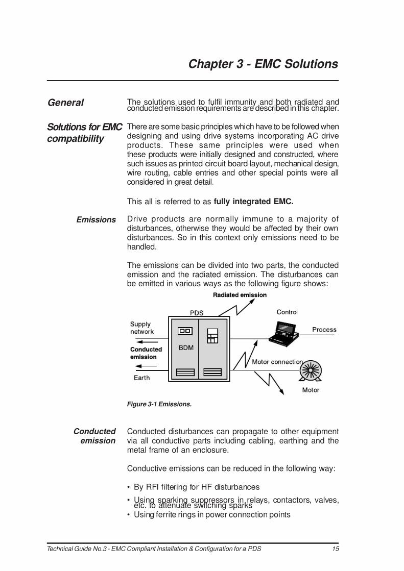
The emissions can be divided into two parts, the conductedemission and the radiated emission. The disturbances canbe emitted in various ways as the following figure shows:
Conducted disturbances can propagate to other equipmentvia all conductive parts including cabling, earthing and themetal frame of an enclosure.
Conductive emissions can be reduced in the following way:
• By RFI filtering for HF disturbances
• Using sparking suppressors in relays, contactors, valves,etc. to attenuate switching sparks
• Using ferrite rings in power connection points
General
Solutions for EMC compatibility
Emissions
Figure 3-1 Emissions.
Conducted emission

7/27/2019 EMC Compliance Tech Guide.pdf
http://slidepdf.com/reader/full/emc-compliance-tech-guidepdf 16/40
Technical Guide No.3 - EMC Compliant Installation & Configuration for a PDS 16
To be able to avoid disturbance through air, all parts of thePower Drive System should form a Faraday Cage againstradiated emissions. The PDS includes cabinets, auxiliaryboxes, cabling, motors, etc.
Some methods for ensuring the continuity of the Faraday Cageare listed as follows:
Enclosure:
• The enclosure must have an unpainted non-corrodingsurface finish at every point that other plates, doors, etc.make contact.
• Unpainted metal to metal contacts shall be usedthroughout, with conductive gaskets, where appropriate.
• Use unpainted installation plates, bonded to commonearth point, ensuring all separate metal items are firmlybonded to achieve a single path to earth.
• Use conductive gaskets in doors and covers. Coversshould be secured at not more than 100 mm intervalswhere radiation could escape.
• Separate radiative i.e. “dirty” side from the “clean side” bymetal covers and design.
• Holes in enclosure should be minimised.• Use materials with good attenuation e.g. plastic with
conductive coating, if a metal enclosure cannot be used.
Cabling & Wiring:
• Use special HF cable entries for high frequency earthing ofpower cable shields.
• Use conductive gaskets for HF earthing of control cableshield.
• Use shielded power and control cables. See product specificmanuals.
• Route power and control cables separately.• Use twisted pairs to avoid common mode disturbances.
• Use ferrite rings for common mode disturbances, if necessary.• Select and route internal wires correctly.
Installation:
• Auxiliaries used with CDMs should be CE marked productsto both EMC & Low Voltage Directives, NOT ONLY to LV-directive, unless they are not concerned, e.g. being with acomponent without a direct function.
• Selection and installation of accessories in accordancewith manufacturers’ instructions.
• 360° earthing at motor end. See product specific manuals.• Correct internal wiring methods.• Special attention must be given to earthing.
Radiated
emission
EMC Solutions

7/27/2019 EMC Compliance Tech Guide.pdf
http://slidepdf.com/reader/full/emc-compliance-tech-guidepdf 17/40
17 Technical Guide No.3 - EMC Compliant Installation & Configuration for a PDS
Note: When selecting equipment for a configuration it isessential to check that both radiated and conductedemissions have been taken into account.
The circuit before the point where supply power is connectedto the CDM and where the filtering starts, is referred to as theclean side. The parts of the BDM which can cause disturbancesare described as the dirty side.
Enclosed wall mounted drives are designed so that the circuitfollowed by output connection is the only dirty part. That isthe case if the installation instructions of the drive are followed.
To be able to keep the clean side “clean” the dirty parts areseparated into a Faraday Cage. This can be done either withseparation plates or with cabling.
When using separation plates the rules for enclosure holesare applicable (see section Holes in enclosures later in thischapter).
When the Faraday cage is formed by cabling, the rules forcabling must be applied (see sections on cabling and wiring in this chapter and follow the product specific instructions for
the drive).
The use of additional components, e.g. contactors, isolators,fuses, etc. in some cases makes it difficult to keep the cleanand the dirty side separate.
This can happen when contactors or switches are used incircuits to change over from clean to dirty side (e.g. by-pass).
Some examples of solutions are described in chapter 4,Practical Examples.
RFI filters are used to attenuate conducted disturbances in aline connecting point where the filter leads the disturbancesto earth.
RFI filters are needed when a PDS is connected to the publiclow-voltage network (First Environment, see chapter 2,Definitions ).
It is also recommended to use filters in industrial situations
(Second Environment), if there are potential victims in theneighbourhood and thus possible EMC problems, even though
Clean and dirty side
RFI filtering
EMC Solutions
7/27/2019 EMC Compliance Tech Guide.pdf
http://slidepdf.com/reader/full/emc-compliance-tech-guidepdf 18/40
Technical Guide No.3 - EMC Compliant Installation & Configuration for a PDS 18
the product standard does not currently give any limits forconducted emissions. That is the case in industrial estateswhere both heavy and light industry and offices are situated.
Figure 3-2 shows an example of integral, distributed filtering.Some drive products need a separate filter (see productspecific instructions).
An RFI filter is selected to attenuate the conducted disturbances.It is not possible to compare the disturbances measured froma source, and the insertion loss for a filter, as the measurementbase for the two items of information will not correspond.
It is always necessary to test a filter in conjunction with thesource of disturbance to ensure adequate attenuation.
Reliable HF/low impedance connections are essential toensure proper functioning of the filter, therefore the followinginstructions shall be followed.
• Filter shall be assembled on a metal plate with unpaintedconnection points all in accordance with filter manufacturer’sinstructions.
• The frames of the filter cubicle (if separate) and the drivecubicle shall be bolted together at several points. Paint
shall be removed from all connection points.• The input and output cables of the filter shall not run inparallel, and must be separated from each other.
Note: Filters cannot be used in floating network (IT-network) where there is high impedance or no physicalconnection between the phases and the earth.
Figure 3-2 Example of filtering integrated in drive module.
Selecting the RFI filter
Installation of the RFI filter
EMC Solutions
7/27/2019 EMC Compliance Tech Guide.pdf
http://slidepdf.com/reader/full/emc-compliance-tech-guidepdf 19/40
19 Technical Guide No.3 - EMC Compliant Installation & Configuration for a PDS
• The maximum length of the cable between the filter andthe drive must be according to the RFI-filter manufacturer'sinstructions.
• The filter must be earthed in accordance with the manu-
facturer’s instructions. Note that the cable type and sizeare critical.
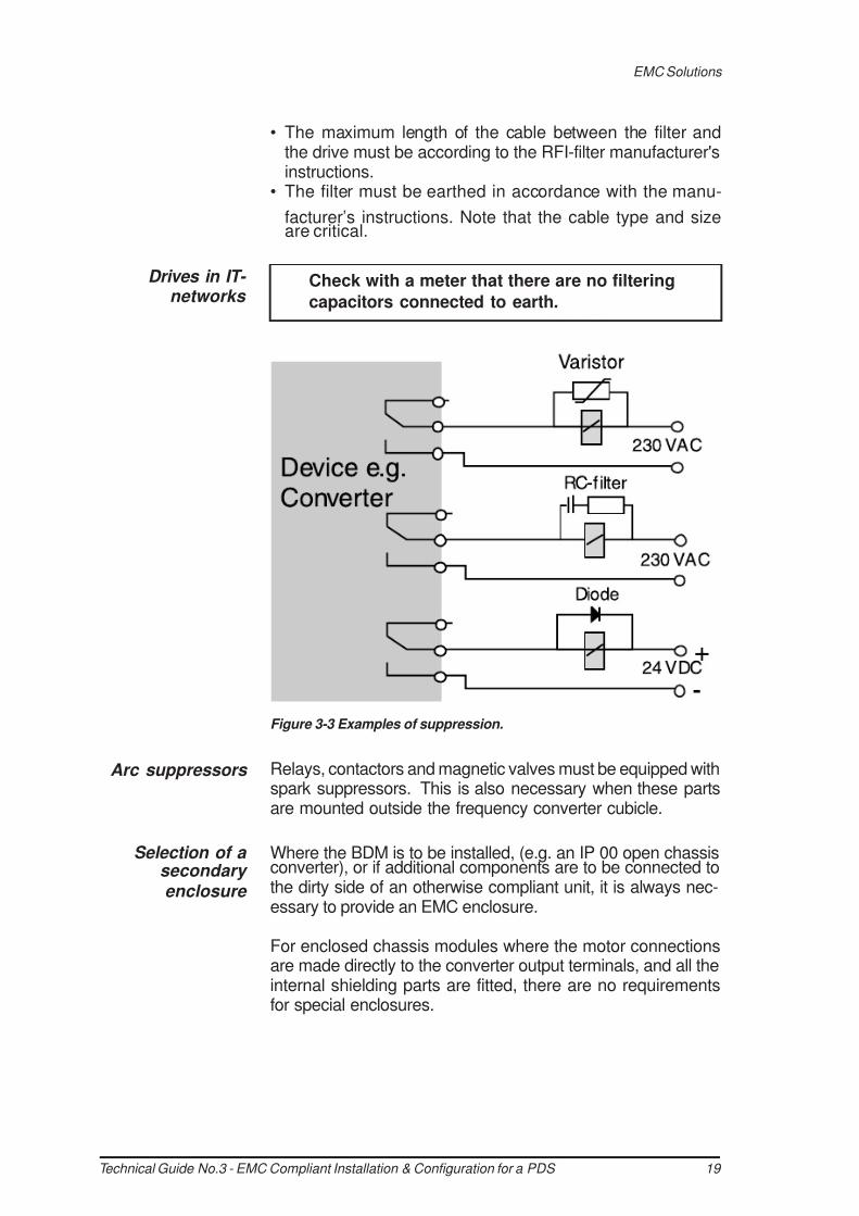
Relays, contactors and magnetic valves must be equipped withspark suppressors. This is also necessary when these partsare mounted outside the frequency converter cubicle.
Where the BDM is to be installed, (e.g. an IP 00 open chassisconverter), or if additional components are to be connected tothe dirty side of an otherwise compliant unit, it is always nec-essary to provide an EMC enclosure.
For enclosed chassis modules where the motor connectionsare made directly to the converter output terminals, and all theinternal shielding parts are fitted, there are no requirementsfor special enclosures.
Check with a meter that there are no filtering
capacitors connected to earth.
Drives in IT- networks
Figure 3-3 Examples of suppression.
Arc suppressors
Selection of a secondary enclosure
EMC Solutions

7/27/2019 EMC Compliance Tech Guide.pdf
http://slidepdf.com/reader/full/emc-compliance-tech-guidepdf 20/40
Technical Guide No.3 - EMC Compliant Installation & Configuration for a PDS 20
If drives are fitted with output switching devices, for example,then an EMC enclosure will be needed, as the integral FaradayCage will no longer apply.
As a reminder, EMC is only one part of enclosure selection.The enclosure is sized according to several criteria:
• Safety• Degree of Protection (IP Rating)• Heat Rejection Capability• Space for accessory equipment• Cosmetic aspects• Cable access• EMC compliance• General requirements for EMC compatibility
The safety of people and animals together with degree ofprotection (IP-rating) requirements are mainly described inMachinery Safety standard EN 60204-1, Electrical SafetyStandard EN 50178 or Product Standard EN 61800-2 andare not described here. In this document only the EMC aspectis handled.
From the EMC point of view it means that the enclosure isfirm and proof enough to be a part of the Faraday Cage. Insmall systems, plastic boxes can also be used if they arepainted inside with conductive paint. The paint must have metalto metal contact at each seam to other parts of the metalenclosure.
External safety switches can also be in plastic boxes if theboxes form a good Faraday Cage and are conductive inside,otherwise metal boxes should be used.
The enclosure must adhere to the following parameters as aminimum:
• Thickness: 0.75 mm stainless (galvanised) steel (Normallyrecommended <1.5 mm for stiffness).
• Outside surface: Electrostatic powder coating e.g. polyesterpowder paint (TGIC). Thickness 60 m, or other cosmeticfinish.
• Inside surface: Hot galvanised and chromated steel. Not painted. The surfaces that make metal to metal contact shall not be painted.
• Louvres: holes in steelwork < 21 mm in width or proprietaryRFI proof type.
• Doors: Sealed with conductive gasket, and adequatelyearthed. Enough locks for high frequency earthing.
EMC Solutions

7/27/2019 EMC Compliance Tech Guide.pdf
http://slidepdf.com/reader/full/emc-compliance-tech-guidepdf 21/40
21Technical Guide No.3 - EMC Compliant Installation & Configuration for a PDS
• Cover plates: Metal against metal (not painted), all earthed.A number of proprietary enclosure types are available, whichuse a variety of materials and methods of shielding againstradiated emissions.
The manufacturer’s guidelines for construction and earthingmust be followed.
In most cases, some holes must be made in the enclosure e.g.for door devices, louvres, locks, cables, etc.
When an EMC enclosure is to be used, the maximum diagonalor diameter for any hole is 100 mm, which equates to 1 / 10
TH ofthe wavelength of a 300 MHz frequency. This dimension hasbeen found acceptable in EMC tests.
It is, however, also recommended to use metal framed devicesif their assembly holes are between 30 mm to 100 mm, if thereis any possible doubt about problems with HF disturbances.
Holes bigger than 100 mm must be covered with a metalframe surrounding the aperture and earthed to the enclosure.
Larger viewing holes can be covered by proprietary glazingwith conductive coating.
Glazing must be connected to non painted metal surrounds
with conductive double sided tape or conductive gasket.
Holes in enclosures
Figure 3-4 Enclosure detail.
EMC Solutions

7/27/2019 EMC Compliance Tech Guide.pdf
http://slidepdf.com/reader/full/emc-compliance-tech-guidepdf 22/40
Technical Guide No.3 - EMC Compliant Installation & Configuration for a PDS 22
360° HF earthing should be done everywhere where cablesenter the drive enclosure, auxiliary connection box or motor.There are different ways to implement the HF earthing. Thesolutions used in ABB’s CDM/BDM products are describedhere.
The cable glands which are specially designed for 360° HFearthing are suitable for power cables with a diameter lessthan 50 mm.
Cable glands are not normally used for control cables due tothe fact that the distance from the control connections to thecable glands is often too long for reliable HF earthing. If theglands are used with control cables, the cable shielding mustcontinue as near to the control connections as possible. Onlythe outer insulation of cable should be removed to expose
the cable screen for the length of the cable gland.
To get the best possible result from HF earthing, the cableshielding should be covered with a conductive tape. The tapemust cover the whole surface of the shielding, including pigtail,and should be tightly pressed with fingers after every singleturn. The glue must be conductive.
360° HF earthing
HF earthing with cable glands
EMC Solutions
Figure 3-5 Typical enclosure aperture detail.
Note: If front plate of door device is plastic, make 360 o earthing for cable,
otherwise twisted pair is acceptable
Maximum size 72 x 72 mm
instrument

7/27/2019 EMC Compliance Tech Guide.pdf
http://slidepdf.com/reader/full/emc-compliance-tech-guidepdf 23/40
23 Technical Guide No.3 - EMC Compliant Installation & Configuration for a PDS
wires as possible
covered with conductive tape
360° HF earthing in power cable entries can be done by usinga conductive sleeve around the cable shielding. The sleeveis connected to the Faraday Cage by tightening it to thespecially designed collar in the gland plate.
The advantage of this solution is that the same sleeve can beused for cables with different diameters.
HF earthing with conductive
sleeve
Figure 3-7 360°earthing with conductive sleeve.
EMC Solutions
Figure 3-6 Essential points of power connections.

7/27/2019 EMC Compliance Tech Guide.pdf
http://slidepdf.com/reader/full/emc-compliance-tech-guidepdf 24/40
Technical Guide No.3 - EMC Compliant Installation & Configuration for a PDS 24
The cable can be mechanically supported by clamps, and aspecific cable gland is not required.
Note that the sleeve does not act as a strain relief clamp.
The continuity of the Faraday Cage at the motor end mustbe ensured by the same methods as in cabinet entry, namely:
• Cable gland must be used for clamping the cable.• Cable shielding should be sealed with conductive tape.• Conductive gaskets should be used for sealing both the
cable gland plate and the terminal box cover for theFaraday Cage and IP 55 degree of protection.
• Earthing pigtail conductors should be as short as possible.
Figure 3-8 shows a Faraday Cage solution at the motor end.
For motors which are not totally enclosed, such as in coolingform IC01, IC06, etc. the continuity of the Faraday Cage mustbe ensured in the same manner as for the converter enclosure.
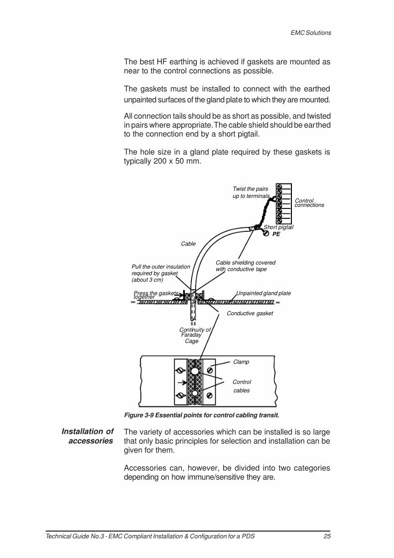
The 360° HF earthing for control cables can be done withconductive gaskets. In this method the shielded control cableis led through two gaskets and pressed tightly together, asthe figure 3-9 shows.
When gaskets are mounted at a gland plate, the cableshielding must continue as near to the control connections aspossible. In this case the outer insulation of the cable shouldbe removed to allow connection to the shield for the length ofthe gasket transit.
The shielding should be covered with conductive tape.
360° earthing at motor end
Conductive gaskets with
control cables
EMC Solutions
Figure 3-8 Essential points in motor cabling.
7/27/2019 EMC Compliance Tech Guide.pdf
http://slidepdf.com/reader/full/emc-compliance-tech-guidepdf 25/40
25 Technical Guide No.3 - EMC Compliant Installation & Configuration for a PDS
Control
cables
Conductive gasket
Cable shielding covered with conductive tape
Unpainted gland plate
Short pigtail
PE
Control connections
Twist the pairs
up to terminals
Cable
Continuity of Faraday
Cage
Clamp
Pull the outer insulation required by gasket (about 3 cm)
Press the gaskets together
The best HF earthing is achieved if gaskets are mounted asnear to the control connections as possible.
The gaskets must be installed to connect with the earthed
unpainted surfaces of the gland plate to which they are mounted.
All connection tails should be as short as possible, and twistedin pairs where appropriate. The cable shield should be earthedto the connection end by a short pigtail.
The hole size in a gland plate required by these gaskets istypically 200 x 50 mm.
The variety of accessories which can be installed is so largethat only basic principles for selection and installation can begiven for them.
Accessories can, however, be divided into two categoriesdepending on how immune/sensitive they are.
Figure 3-9 Essential points for control cabling transit.
Installation of accessories
EMC Solutions

7/27/2019 EMC Compliance Tech Guide.pdf
http://slidepdf.com/reader/full/emc-compliance-tech-guidepdf 26/40
Technical Guide No.3 - EMC Compliant Installation & Configuration for a PDS 26
The protected device in this context means its ability to keepthe Faraday Cage closed. It is therefore recommended touse metal enclosed/shielded devices wherever such devicesare available.
The rules for holes in the enclosure must be applied if thereare devices forming a bridge between the clean side and thedirty side which can be disturbed.
Typical open devices are fuses, switch fuses, contactors etc.,which do not have a metal covering around them.
In general, such devices cannot be installed into the cleanside without protective metallic shielding plates. The rules forholes in the enclosure must then be applied.
In some cases there might be some confusion betweensafety and EMC requirements. It is therefore important to
remember the following basic rule:
Some examples of protected and open devices are given inthe chapter Practical Examples .
There are some basic rules for internal wiring:• Always keep clean and dirty side cables separate and
shielded from one another.• Internal clean power connections with integrally filtered drive
units, e.g. from contactor to converter input, do not requireshielded cables but may require de-coupling ferrite ringswhere they enter the converter input.
• Use twisted pair wires wherever possible.• Use shielded twisted pairs for signal level outward and
return wires exiting from the overall enclosure.• Avoid mixing pairs with different signal types e.g. 110 VAC,230 VAC, 24 VDC, analogue, digital.
• Run wires along the metal surface and avoid wires hangingin free air, which can become an antenna.
• If plastic trunking is used, secure it directly to installationplates or framework. Do not allow spans over free air whichcould form an antenna.
• Keep power and control wiring separate.• Use galvanically isolated (potential free) signals.• Keep wires twisted as near the terminal as possible.
• Keep pigtails as short as possible.• Earthing connections should be as short as possible in flatstrip, multistranded or braided flexible conductors for lowRFI impedance.
Internal wiring
Safety is always the first priority and overrules the
EMC requirements.
EMC Solutions
7/27/2019 EMC Compliance Tech Guide.pdf
http://slidepdf.com/reader/full/emc-compliance-tech-guidepdf 27/40
27 Technical Guide No.3 - EMC Compliant Installation & Configuration for a PDS
DIGITAL INPUTS
RELAY OUTPUTS (pot.free)
RC filter or varistor for AC relay
Avoid parallel running with control wires Cross in 90˚ angle
Avoid parallel running with control wires
Cross in 90˚ angle
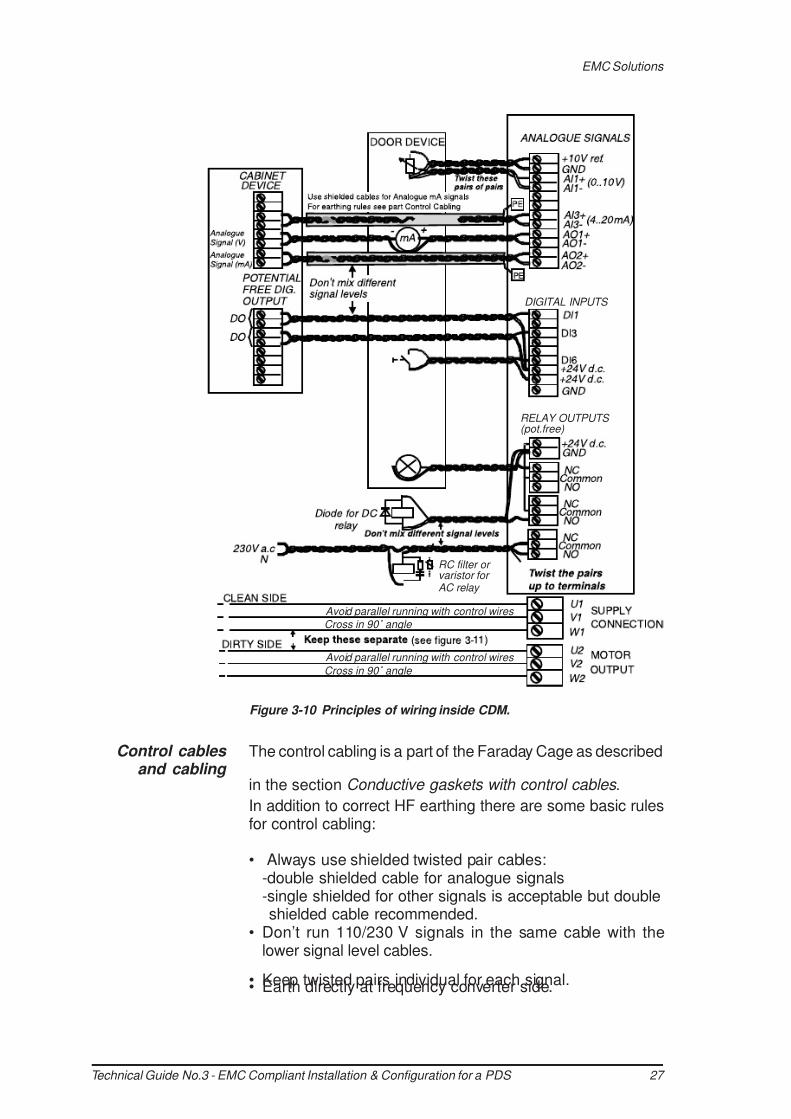
The control cabling is a part of the Faraday Cage as described
in the section Conductive gaskets with control cables .
In addition to correct HF earthing there are some basic rulesfor control cabling:
• Always use shielded twisted pair cables:-double shielded cable for analogue signals-single shielded for other signals is acceptable but doubleshielded cable recommended.
• Don’t run 110/230 V signals in the same cable with thelower signal level cables.
• Keep twisted pairs individual for each signal.• Earth directly at frequency converter side.
Figure 3-10 Principles of wiring inside CDM.
Control cables and cabling
EMC Solutions

7/27/2019 EMC Compliance Tech Guide.pdf
http://slidepdf.com/reader/full/emc-compliance-tech-guidepdf 28/40
Technical Guide No.3 - EMC Compliant Installation & Configuration for a PDS 28
Mains cable
Motor cable
If instructions for the device at the other end of the cablespecify earthing at that end, earth the inner shields atthe end of the more sensitive device and the outer shieldat the other end.
• Route signal cables according to figure 3-11 wheneverpossible and follow instructions given by the product specificmanuals.
There is more about control cabling in the documents“Grounding and cabling of the drive system” and inproduct specific manuals.
As the cables are part of the PDS they are also part of theFaraday Cage. To be able to meet the EMC requirements,power cables with good shielding effectiveness must be used.
The purpose of the shield is to reduce radiated emission.
In order to be efficient, the shield must have good conductivityand cover most of the cable surface. If the cable shield is usedas protective earthing, the shield cross area (or equivalentconductivity) must be at least 50 % of the cross sectional areaof the phase conductor.
Power cables
EMC Solutions
Figure 3-11 Routing principles of control cables.
7/27/2019 EMC Compliance Tech Guide.pdf
http://slidepdf.com/reader/full/emc-compliance-tech-guidepdf 29/40
29 Technical Guide No.3 - EMC Compliant Installation & Configuration for a PDS
3 2
1
3
3 1
3 2
3 2
1
3
3 3
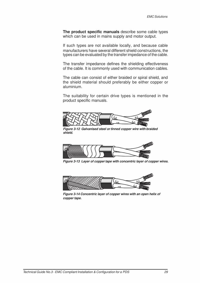
The product specific manuals describe some cable typeswhich can be used in mains supply and motor output.
If such types are not available locally, and because cable
manufacturers have several different shield constructions, thetypes can be evaluated by the transfer impedance of the cable.
The transfer impedance defines the shielding effectivenessof the cable. It is commonly used with communication cables.
The cable can consist of either braided or spiral shield, andthe shield material should preferably be either copper oraluminium.
The suitability for certain drive types is mentioned in theproduct specific manuals.
Figure 3-12 Galvanised steel or tinned copper wire with braided shield.
Figure 3-13 Layer of copper tape with concentric layer of copper wires.
Figure 3-14 Concentric layer of copper wires with an open helix of
copper tape.
EMC Solutions
7/27/2019 EMC Compliance Tech Guide.pdf
http://slidepdf.com/reader/full/emc-compliance-tech-guidepdf 30/40
Technical Guide No.3 - EMC Compliant Installation & Configuration for a PDS 30
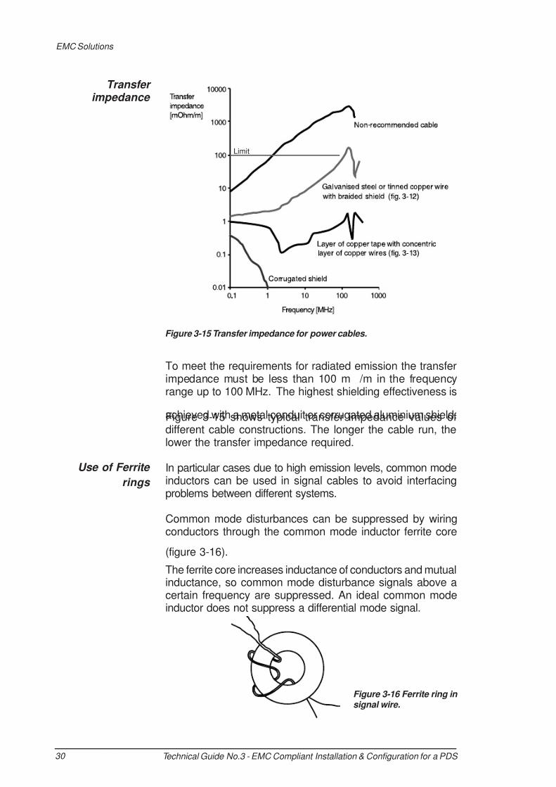
To meet the requirements for radiated emission the transferimpedance must be less than 100 m /m in the frequencyrange up to 100 MHz. The highest shielding effectiveness is
achieved with a metal conduit or corrugated aluminium shield.Figure 3-15 shows typical transfer impedance values ofdifferent cable constructions. The longer the cable run, thelower the transfer impedance required.
In particular cases due to high emission levels, common modeinductors can be used in signal cables to avoid interfacingproblems between different systems.
Common mode disturbances can be suppressed by wiringconductors through the common mode inductor ferrite core
(figure 3-16).
The ferrite core increases inductance of conductors and mutualinductance, so common mode disturbance signals above acertain frequency are suppressed. An ideal common modeinductor does not suppress a differential mode signal.
Figure 3-15 Transfer impedance for power cables.
Use of Ferrite
rings
Transfer impedance
Figure 3-16 Ferrite ring in signal wire.
EMC Solutions
Limit

7/27/2019 EMC Compliance Tech Guide.pdf
http://slidepdf.com/reader/full/emc-compliance-tech-guidepdf 31/40
31Technical Guide No.3 - EMC Compliant Installation & Configuration for a PDS
The inductance (i.e. the ability to suppress HF disturbances)can be increased by multiple turns of the signal wire.
When using a ferrite ring with power cable, all phase conductors
should be led through the ring. The shielding and possible earthwire must be wired outside the ring to keep the common modeinductor effect. With power cables it is not normally possible tomake multiple turns through the ring. The inductance can beincreased by using several successive rings.
If for any reasons the installation instructions cannot befollowed and therefore additional ferrites or filters are addedafterwards, it is recommended that measurements be madeto show conformance.
EMC Solutions
7/27/2019 EMC Compliance Tech Guide.pdf
http://slidepdf.com/reader/full/emc-compliance-tech-guidepdf 32/40
Technical Guide No.3 - EMC Compliant Installation & Configuration for a PDS 32
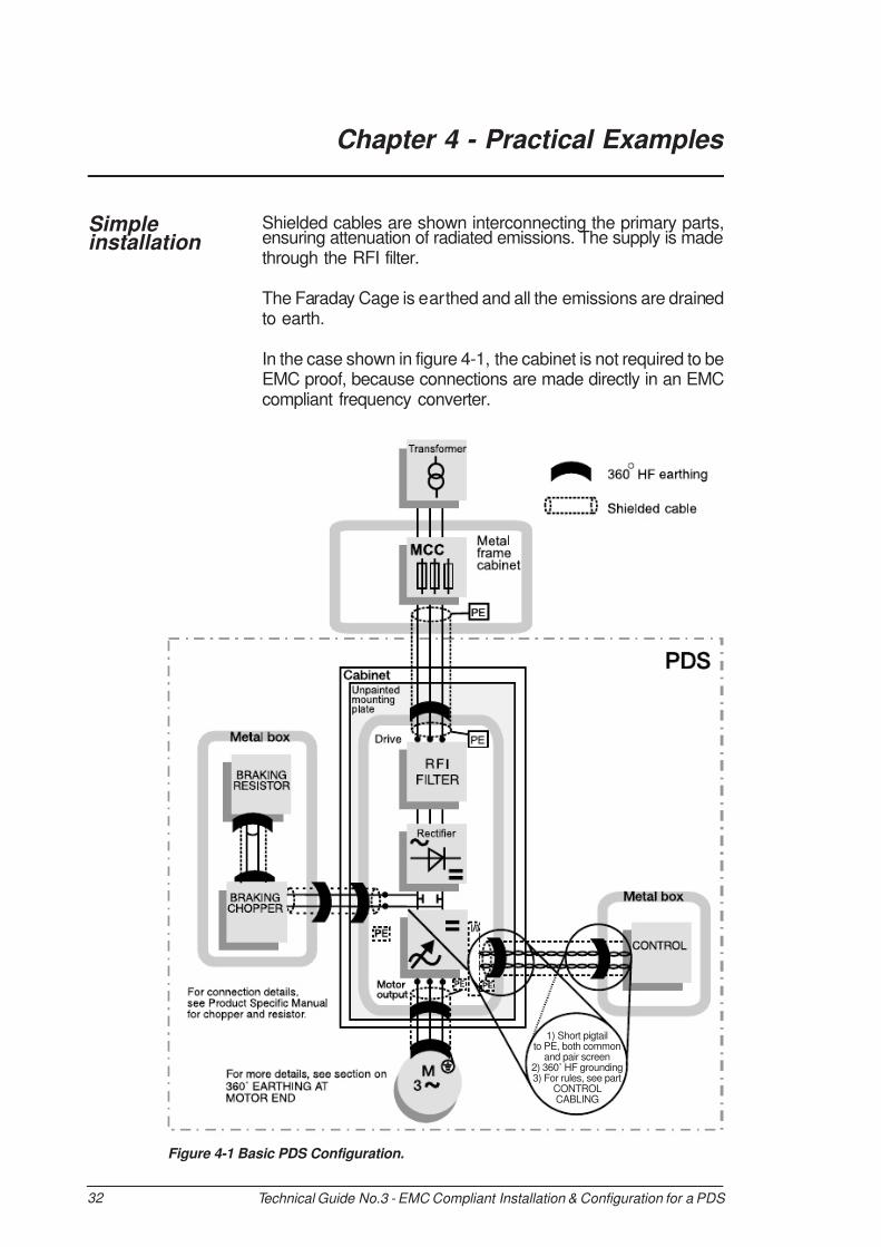
1) Short pigtailto PE, both common
and pair screen2) 360˚ HF grounding3) For rules, see part
CONTROLCABLING
Chapter 4 - Practical Examples
Shielded cables are shown interconnecting the primary parts,ensuring attenuation of radiated emissions. The supply is madethrough the RFI filter.
The Faraday Cage is earthed and all the emissions are drainedto earth.
In the case shown in figure 4-1, the cabinet is not required to beEMC proof, because connections are made directly in an EMCcompliant frequency converter.
Figure 4-1 Basic PDS Configuration.
Simple installation

7/27/2019 EMC Compliance Tech Guide.pdf
http://slidepdf.com/reader/full/emc-compliance-tech-guidepdf 33/40
33 Technical Guide No.3 - EMC Compliant Installation & Configuration for a PDS
For more details, see360˚ MOTOR EARTHING
Cabinet 1Supplyconnection
In this case it is difficult to ensure that no cross coupling occursbetween the dirty side of the converter and the clean side abovethe Direct On Line (DOL) contactor. Contactors are not RFIbarriers, and the coil circuits are also vulnerable.
A suitable RFI filter at the supply input connections would requireto be able to pass the DOL starting current, which can be sixto seven times the normal Full Load Current, and would begreatly oversized for normal running, which makes it difficult todesign. Ferrite cores used in the feeds to the contactor willhelp attenuate the coupled noise as shown in figure 4-2.
Figure 4-2 Basic scheme with By-pass.
Practical Examples
Example of By-pass system <100kVA

7/27/2019 EMC Compliance Tech Guide.pdf
http://slidepdf.com/reader/full/emc-compliance-tech-guidepdf 34/40
Technical Guide No.3 - EMC Compliant Installation & Configuration for a PDS 34
Low voltage supply
In this case a 12-pulse rectifier is an IT system, uneartheddue to the delta winding, therefore any filter in the line mustbe at the primary of the phase shift transformer.
Experience has shown that, in this case, with short connectionsto the busbars, the earth shield between the transformerwindings is not quite adequate for conducted emissionsattenuation for use in the first environment. Therefore an RFIfilter may be needed at the primary side of the transformer forEMC compliance. RFI filter is not normally needed for secondenvironment.
For equipment fed from an IT system, a similar procedure canbe used. An isolating transformer allows the PDS to be earthedand to use a suitable filter, for use in the First Environment.
The Point of Coupling is at a medium voltage and emissionsmay be considered at the next low voltage point of couplingin the system. The level of emissions should correspond tothose for the appropriate environment. For definitions, seesection Installation Environments in chapter 2.
Note: All equipment inside must be enclosed
Figure 4-3 12-pulse converter system fed at LV.
Practical Examples
Typical example of 12-pulse drive

7/27/2019 EMC Compliance Tech Guide.pdf
http://slidepdf.com/reader/full/emc-compliance-tech-guidepdf 35/40
35 Technical Guide No.3 - EMC Compliant Installation & Configuration for a PDS
Figure 4-4 12-pulse converter system fed at LV (CDM, transformer and switch fuse have separate housing).
Figure 4-5 12-pulse converter system fed at medium or high voltage.

7/27/2019 EMC Compliance Tech Guide.pdf
http://slidepdf.com/reader/full/emc-compliance-tech-guidepdf 36/40
Technical Guide No.3 - EMC Compliant Installation & Configuration for a PDS 36
CommonEarth
Example of common DC fed sectional
drive
This example features a common DC bus sectional drive whichis supplied from an earthed network through an RFI filter.
The enclosure must be EMC proof as the components inside
are not. Cable entries must be 360°HF earthed. The enclosureis earthed to drain away all emissions.
Figure 4-6 Common DC bus fed sectional drive fed at LV

7/27/2019 EMC Compliance Tech Guide.pdf
http://slidepdf.com/reader/full/emc-compliance-tech-guidepdf 37/40
37 Technical Guide No.3 - EMC Compliant Installation & Configuration for a PDS
Chapter 5 - Bibliography
Various texts are referred to in this guide. They arerecommended further reading to assist in achieving compliantinstallations:
EN 61800-3, Adjustable Speed Electrical Power DriveSystems - point 3, EMC product standard including specifictest (published by CENELEC, Brussels, Belgium and NationalStandards organisations in EU member countries).
Guidelines by the Commission on the application of CouncilDirective 89/336/EEC, published by European Commission
DGIII - Industry.
Interference Free Electronics by Dr. Sten Benda (publishedby ABB Industry Ab, Västerås, Sweden)
Technical Guide No. 2 - EU Council Directives and AdjustableSpeed Electrical Power Drive Systems, code 3BFE 61253980RO125 REV B (published by ABB Industry Oy, Helsinki,Finland)
Grounding and cabling of the drive system, code 3AFY61201998 (published by ABB Industry Oy, Helsinki, Finland)

7/27/2019 EMC Compliance Tech Guide.pdf
http://slidepdf.com/reader/full/emc-compliance-tech-guidepdf 38/40
Technical Guide No.3 - EMC Compliant Installation & Configuration for a PDS 38
Chapter 6 - Index
12-pulse rectifier 34
Aantenna 26apparatus 11BBasic Drive Module (BDM) 8, 17, 19Ccabinet 16, 24, 32cable gland 22, 24CE mark 3, 5, 10, 11, 16CENELEC 9, 37Complete Drive Module (CDM) 8, 27Component 3, 5, 8, 9, 11, 16, 17, 19
conducting radio frequencydisturbance 8conduction 8Conductive gasket 16, 20, 21,24, 27Contactor 5, 15, 17, 19, 26, 33Control Cable 16, 22, 24, 27, 28control connection 22, 24, 25control electronics 8converter 8, 19, 24, 26, 27, 33,34, 35cross coupling 33customer 13D
delta winding 34direct function 16DOL 33double shielded cable 27drive 1, 3, 5, 6, 8, 9, 12, 13, 15,16,17, 18, 19, 22, 26, 28, 29, 37EEEA 8electrical surge 8Electromagnetic Compatibility(EMC) 1, 3, 5, 6, 8, 9, 12, 13, 15,16, 17, 18, 19, 20, 21, 22, 23, 24, 25,26, 27, 28, 29, 30, 31, 32, 34, 37
electromagnetic disturbance 9electromagnetic environment 8electrostatic discharge 8enclosure 15, 16, 17, 19, 20, 21,22, 24, 26Environment Class 11, 12FFaraday Cage 16, 17, 19, 20, 23,24, 26, 27, 28, 32fast transient burst 8
ferrite core 33
Ferrite ring 15, 16, 26, 30, 31First Environment 3, 12, 34frequency converter 8, 19, 27, 32fuse 5, 17, 26Ggasket 16, 20, 21, 24, 25, 27gland plate 23, 24, 25Hharmonics 8high-frequency emission 8High-frequency phenomena 8IIGBT 8
imbalance 8Installation Environment 3, 11, 13, 34isolating transformer 34IT system 34LLow Voltage Directive 5low-frequency phenomena 8low-voltage network 12, 17MMachinery Directive 5medium voltage network 12metallic screening 26motor 24
Nnotches 8OOriginal Equipment Manufacturers(OEM) 5, 6, 9PPanelbuilder 5, 6, 9Power Drive System (PDS) 1, 3,6, 8, 9, 11, 12, 13, 14, 16, 17, 28,32, 34, 37phase shift transformer 34pigtail 24, 26plastic trunking 26
Point of Coupling 34power components 8power distribution networks 11power supply network 12, 13Rradiating electromagnetic field 8radiation 8, 16Restricted Distribution 3, 12, 13RF impedance 26RFI filter 15, 17, 18, 32, 33
7/27/2019 EMC Compliance Tech Guide.pdf
http://slidepdf.com/reader/full/emc-compliance-tech-guidepdf 39/40
39 Technical Guide No.3 - EMC Compliant Installation & Configuration for a PDS
SSales distribution 12, 13
Second Environment 3, 11, 12Shielded cable 26, 32single commercial unit 11single functional unit 11strain relief clamp 24suppliers 13System Integrator 5Ttransformer 12, 34twisted pair 16, 22, 26, 27UUnrestricted 3, 12, 13Unrestricted Distribution 3, 13
user 5, 9, 12, 13VVariable Speed Drives (VSD) 5,6, 8, 16, 17, 22, 37

7/27/2019 EMC Compliance Tech Guide.pdf
http://slidepdf.com/reader/full/emc-compliance-tech-guidepdf 40/40
ABB Industry OyDrivesP.O. Box 184FIN-00381 HelsinkiFINLAND
Tel: +358 10 222 000
c o p y r i g h t © A
B B A
u t o m a t i o n G r o u p L t d , 1 9 9 9
3 B F E 6 1 3 4 8 2 8 0 R 0 2 2 5
S p e c i f i c a t i o n s s u b j e c t t o c h a n g e w i t h o u t n o t i c e
E N 0 1 . 1 2 . 1 9
9 9
N O R D I C E
N V I
R O
N M E N T
A L
LA BEL
4 1 1
0 1 4
P r i n t e d m a t t e r