emi/emc design applications - ansys uk/staticassets/01_em… · emi/emc design applications...
TRANSCRIPT

© 2010 ANSYS, Inc. All rights reserved. 1 ANSYS, Inc. Proprietary© 2010 ANSYS, Inc. All rights reserved. 1 ANSYS, Inc. Proprietary
EMI/EMC Design
Applications
Dr.-Ing. Leon Voss
ANSYS Inc.
© 2010 ANSYS, Inc. All rights reserved. 2 ANSYS, Inc. Proprietary
Overview
• Introduction EMC / EMI
• Power Electronics Systems
• Workflow for Inverter Study
• Parasitic extraction
• IGBT characterization
• System simulation
• Emitted fields

© 2010 ANSYS, Inc. All rights reserved. 3 ANSYS, Inc. Proprietary
Electromagnetic Compatibility
EMC vs. EMI
• Electromagnetic compatibility (EMC) is the
study of the unintentional generation, propagation
and reception of electromagnetic energy
• Electromagnetic interference (EMI) is the
unwanted effect that such energy may induce.

© 2010 ANSYS, Inc. All rights reserved. 4 ANSYS, Inc. Proprietary
Electromagnetic Compatibility
Basic Coupling Modes
Source:
Wikipedia
© 2010 ANSYS, Inc. All rights reserved. 5 ANSYS, Inc. Proprietary
Electromagnetic Compatibility
Emission and Susceptibility
• Emission issues are related to the unwanted
generation of electromagnetic energy by
some source
• Susceptibility or immunity issues, in contrast,
refer to the correct operation of electrical
equipment, referred to as the victim, in the
presence of unplanned electromagnetic
disturbances.

© 2010 ANSYS, Inc. All rights reserved. 6 ANSYS, Inc. Proprietary
DC Hz kHz MHz GHz ???
HFSS – 2 wavelength long line
– 2 wavelengths are apparent
Low: Maxwell, Q3D
High: HFSS
Maxwell: Quasi Static
Ansoft EM Solvers
Maxwell vs HFSS

© 2010 ANSYS, Inc. All rights reserved. 7 ANSYS, Inc. Proprietary
D
t
DJH
B
t
ΒΕ
y Electricit forLawsGauss'
Law sAmpere'
MagnetismforLawsGauss'
InductionofLawsFaraday'
0
Differential Form of Maxwell’s
Equations
Full-wave (e.g. HFSS)

© 2010 ANSYS, Inc. All rights reserved. 8 ANSYS, Inc. Proprietary
D
t
DJH
B
t
ΒΕ
y Electricit forLawsGauss'
Law sAmpere'
MagnetismforLawsGauss'
InductionofLawsFaraday'
0
Example: Maxwell:
Magnetic Transient Formulation
Quasi-Static:
e.g. Maxwell,
Q3D

© 2010 ANSYS, Inc. All rights reserved. 9 ANSYS, Inc. Proprietary
Variable-Speed Drive
Classical Design Issues

© 2010 ANSYS, Inc. All rights reserved. 10 ANSYS, Inc. Proprietary
Variable Speed Drive
EMC/EMI Issues
• Classical Design Considerations:
Conducted low-frequency phenomena
– Harmonic Line Currents
(16.7Hz-60Hz, n<= 49
– Interharmonics, Flicker
– Overvoltages
– Harmonic Motor Currents
(0 – 500Hz, n<= 49)
• Analysis of these Phenomena with Simulation
tools like Simplorer is “State of the Art”
Interaction of Converter
with Supply Network
Interaction of Converter
with Motor & Mechanics
© 2010 ANSYS, Inc. All rights reserved. 11 ANSYS, Inc. Proprietary
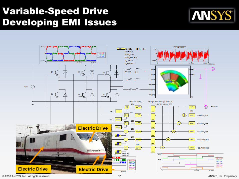
Variable-Speed Drive
Developing EMI Issues
Electric Drive Electric Drive
Electric Drive

© 2010 ANSYS, Inc. All rights reserved. 12 ANSYS, Inc. Proprietary
Variable Speed Drive
EMC/EMI Issues
• Developing Issues
– Power electronics being installed closer to
humans (e.g. ICE3 train or Hybrid car)
– Switching Frequencies are increasing
• Higher Radiating Content
• Frequency dependence of electrical parts
becomes more relevant (e.g. skin effect)

© 2010 ANSYS, Inc. All rights reserved. 13 ANSYS, Inc. Proprietary
Variable Speed Drive
EMC/EMI Issues
• Resulting Problems and Challenges
– Bearing Currents (Common mode problem)
– Insulation Fatique
– Losses / Thermal Problems
– Electromagnetic Field Limits
Higher Requirement on Impedance
Characterisation of the system at higher frequencies
Require Simulation techniques not traditionally
applied in this area

© 2010 ANSYS, Inc. All rights reserved. 14 ANSYS, Inc. Proprietary
AM3~
Traction SupplyPantograph Traction
Motor
InverterInverter LegIGBT Module Top Row
• These power converters are used in high speed trains (TGV)
High Power Inverter Application
© 2010 ANSYS, Inc. All rights reserved. 15 ANSYS, Inc. Proprietary
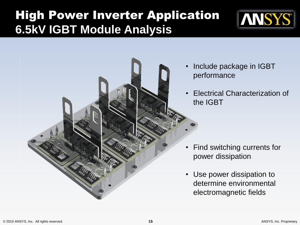
• Include package in IGBT
performance
• Electrical Characterization of
the IGBT
• Find switching currents for
power dissipation
• Use power dissipation to
determine environmental
electromagnetic fields
High Power Inverter Application
6.5kV IGBT Module Analysis
© 2010 ANSYS, Inc. All rights reserved. 16 ANSYS, Inc. Proprietary
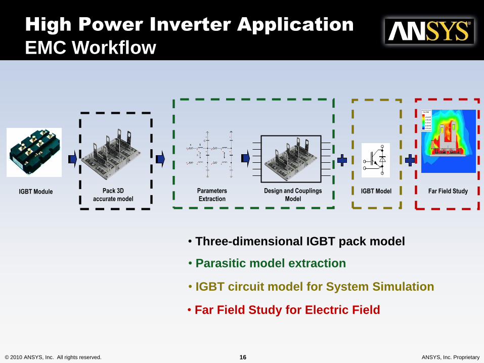
IGBT Module Pack 3D
accurate model
Parameters
Extraction
Design and Couplings
ModelIGBT Model
• Parasitic model extraction
• IGBT circuit model for System Simulation
Far Field Study
• Far Field Study for Electric Field
• Three-dimensional IGBT pack model
High Power Inverter Application
EMC Workflow

© 2010 ANSYS, Inc. All rights reserved. 17 ANSYS, Inc. Proprietary
• Three-dimensional IGBT pack model
• Parasitic model extraction
• IGBT circuit model
• Far Field Study for Electric Field EM
Quasi-static
Boundary Element
Method
Full-wave
Finite Element
Method
Electronic
Circuit
Simulation
High Power Inverter Application
Simulation Techniques

© 2010 ANSYS, Inc. All rights reserved. 18 ANSYS, Inc. Proprietary
EMI/EMC
Electrical Parasitics Extraction
• Extract the resistance, inductance, capacitance and conductance
(RLCG) parameters of the entire package
Low Frequency High Frequency
Ansoft Q3D
Frequency can have a significant impact on the design performance

© 2010 ANSYS, Inc. All rights reserved. 19 ANSYS, Inc. Proprietary
• Extracting parameters is straightforward as the nets are
automatically assigned
EMI/EMC
Electrical Parasitics Extraction
Negative Bar
Positive Bar
Phase A
Phase B
Phase C
© 2010 ANSYS, Inc. All rights reserved. 20 ANSYS, Inc. Proprietary
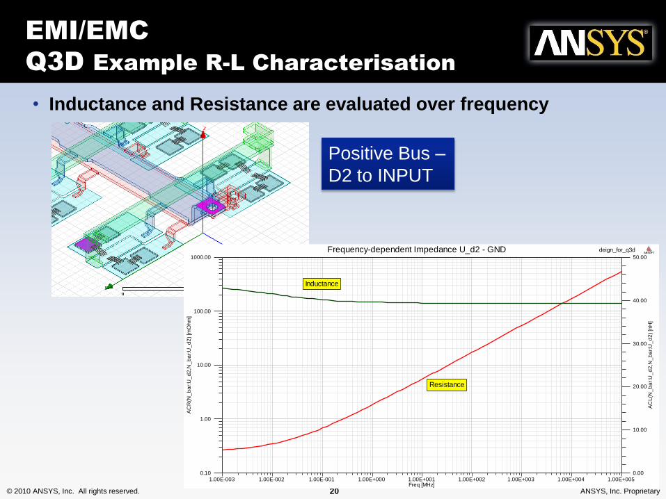
• Inductance and Resistance are evaluated over frequency
EMI/EMC
Q3D Example R-L Characterisation
Positive Bus –
D2 to INPUT
1.00E-003 1.00E-002 1.00E-001 1.00E+000 1.00E+001 1.00E+002 1.00E+003 1.00E+004 1.00E+005Freq [MHz]
0.10
1.00
10.00
100.00
1000.00
AC
R(N
_b
ar:
U_
d2
,N_
ba
r:U
_d
2)
[mO
hm
]
0.00
10.00
20.00
30.00
40.00
50.00
AC
L(N
_b
ar:
U_
d2
,N_
ba
r:U
_d
2)
[nH
]
Curve Info
ACR(N_bar:U_d2,N_bar:U_d2)
ACL(N_bar:U_d2,N_bar:U_d2)
deign_for_q3dFrequency-dependent Impedance U_d2 - GND ANSOFT
Inductance
Resistance

© 2010 ANSYS, Inc. All rights reserved. 21 ANSYS, Inc. Proprietary
EMI/EMC
Parasitics Extraction
• The simulation outputs consist of the RLC matrices, one for each frequency
of interest.

© 2010 ANSYS, Inc. All rights reserved. 22 ANSYS, Inc. Proprietary
EMI/EMC
IGBT Mesh and Field Result
The structure is meshed
using automatic and
adaptive meshing
Current Distribution
© 2010 ANSYS, Inc. All rights reserved. 23 ANSYS, Inc. Proprietary
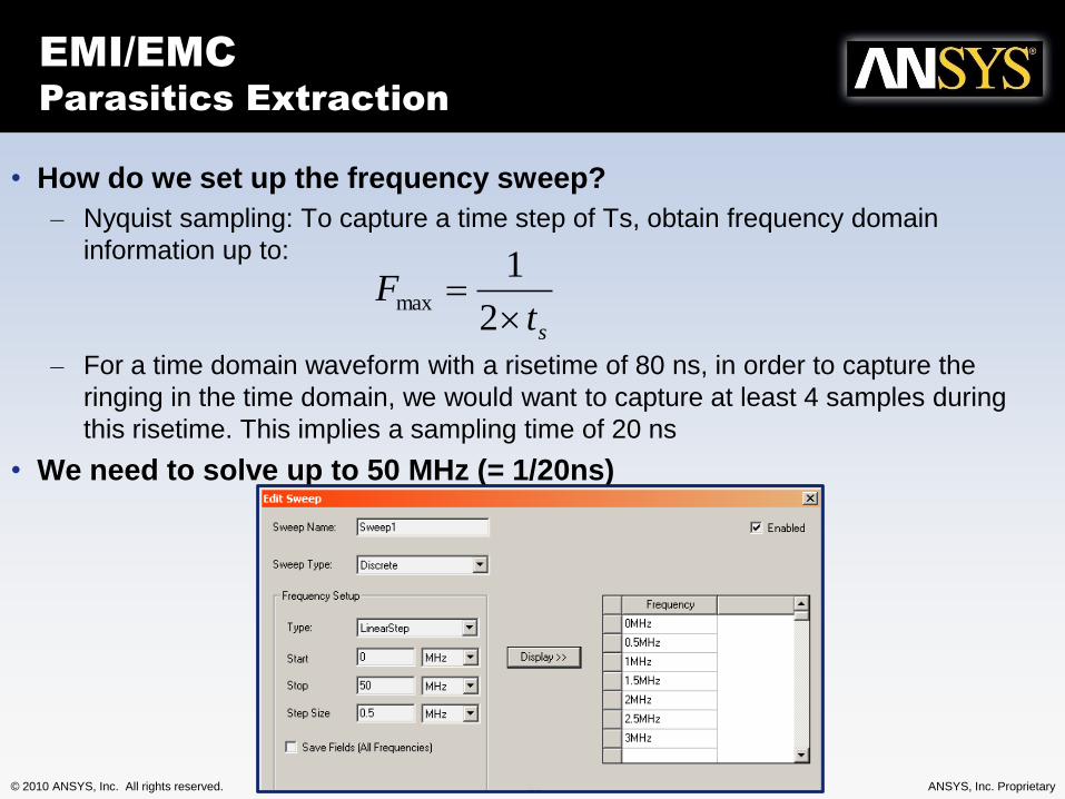
• How do we set up the frequency sweep?
– Nyquist sampling: To capture a time step of Ts, obtain frequency domain
information up to:
– For a time domain waveform with a risetime of 80 ns, in order to capture the
ringing in the time domain, we would want to capture at least 4 samples during
this risetime. This implies a sampling time of 20 ns
• We need to solve up to 50 MHz (= 1/20ns)
stF
2
1max
EMI/EMC
Parasitics Extraction

© 2010 ANSYS, Inc. All rights reserved. 24 ANSYS, Inc. Proprietary
SheetScan
IGBT Characterization

© 2010 ANSYS, Inc. All rights reserved. 25 ANSYS, Inc. Proprietary
IGBT Device Generation
Characterization Tool
Extraction of the IGBT Electro-Thermal Parameters
Tran
sfer
ch
arac
teri
stic
curv
e fr
om
dat
ash
eet
Fit
ted
cu
rve
vs. m
easu
red
dat
a
Measured Data
Fitted Curve
Extracted parameter values

© 2010 ANSYS, Inc. All rights reserved. 26 ANSYS, Inc. Proprietary
IGBT Family
Electro-Thermal Model
DC core
A
Energy calculation
B
Thermal network
F
DC core
A C
Thermal network
F
Capacities C(V), C(I)parasitics L, R, Ccontrolled sources
E
Full parameter excess
Maximum simulation speed:
• Accurate static behaviour
• Accurate thermal response
• No voltage and current transients
• Suitable for system design analysis
Average IGBT Model Dynamic IGBT Model
Maximum simulation accuracy:
• Sophisticated semiconductor based model
• Accurate static, dynamic and thermal
behaviour
• Accurate gate voltage and current waveforms
• Suitable for drive optimization, EMI/EMC

© 2010 ANSYS, Inc. All rights reserved. 27 ANSYS, Inc. Proprietary
The Dynamic IGBT Model
• Dynamic IGBT shares the same static the Average model
• The switching energy of the Dynamic IGBT model is the direct
integration of the switching voltage and current

© 2010 ANSYS, Inc. All rights reserved. 28 ANSYS, Inc. Proprietary
The Dynamic IGBT Model (2)
• Dynamic IGBT accurately captures the switching waveforms
• Suitable for EMI/EMC analysis
© 2010 ANSYS, Inc. All rights reserved. 30 ANSYS, Inc. Proprietary
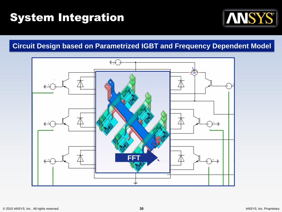
Circuit Design based on Parametrized IGBT and Frequency Dependent Model
System Integration
FFT

© 2010 ANSYS, Inc. All rights reserved. 31 ANSYS, Inc. Proprietary
Vce
Vg
Vge
Ic
Power
The power pulse duration is much smaller than the rise/fall time of Ic and Vce
System Simulation

© 2010 ANSYS, Inc. All rights reserved. 32 ANSYS, Inc. Proprietary
Circuit Design based on Parametrized IGBT and Frequency Dependent Model
System Integration
-22.50
60.00
0
25.00
50.00
0 240.00m100.00m
2DGraphSel1 NIGBT71.IC
Extract Power Loss
0
474.00m
200.00m
400.00m
100.00 1.00Meg1.00k 3.00k 10.00k 100.00k
2DGraphCon1
GS_I...
FFT

© 2010 ANSYS, Inc. All rights reserved. 33 ANSYS, Inc. Proprietary
0
474.00m
200.00m
400.00m
100.00 1.00Meg1.00k 3.00k 10.00k 100.00k
2DGraphCon1
GS_I...
Freq. res.
Normalized S para.MagE@10m by
specified inputs
Multiplied magE plots
by Simplorer
Emission Test
Full Wave Effect
Ansoft HFSS

© 2010 ANSYS, Inc. All rights reserved. 34 ANSYS, Inc. Proprietary
Emitted Fields
For each frequency, the power amplitude is entered
Spectrum (MHz)Power
(W)E field at 1m for 1000w
(V/m)E field at 1m
(V/m)
16.52892562 21439.97604 2.6312 56.41286497
33.05785124 8635.09049 2.7994 24.17307232
49.58677686 5579.619715 2.8731 16.0308054
66.11570248 4131.16773 3.063 12.65376676
82.6446281 3276.823585 3.4045 11.15594589
99.17355372 2712.888158 3.8924 10.55964586
115.7024793 2308.359536 4.4861 10.35553171
132.231405 2022.75744 4.905 9.921625241
Spectrum from Simplorer
Outputs from Simplorer
Inputs for HFSS
Outputs From HFSS
(normalized results)
Fields Levels
© 2010 ANSYS, Inc. All rights reserved. 35 ANSYS, Inc. Proprietary
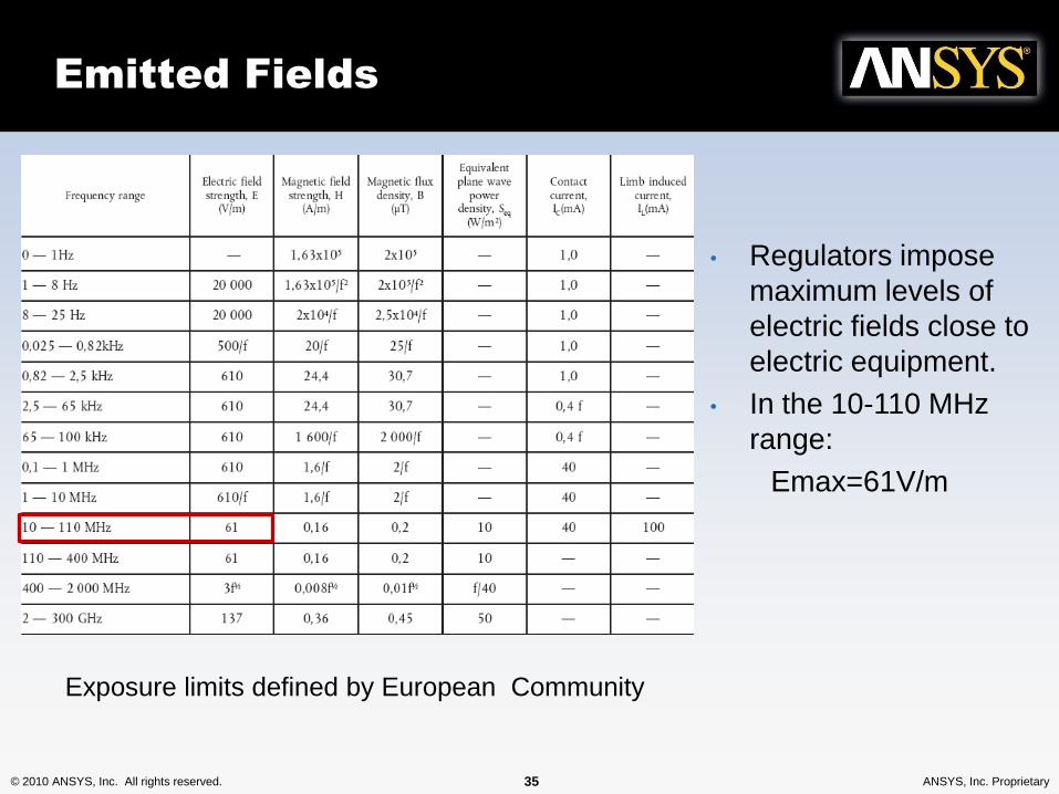
Emitted Fields
• Regulators impose
maximum levels of
electric fields close to
electric equipment.
• In the 10-110 MHz
range:
Emax=61V/m
Exposure limits defined by European Community
© 2010 ANSYS, Inc. All rights reserved. 36 ANSYS, Inc. Proprietary
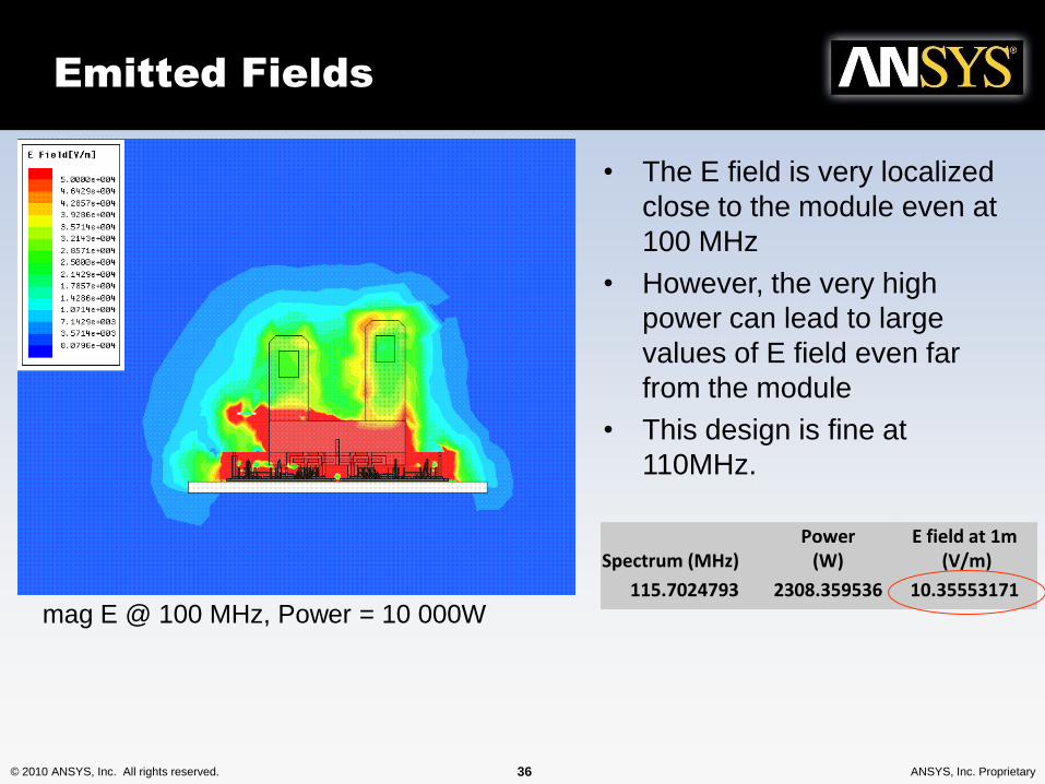
Emitted Fields
• The E field is very localized
close to the module even at
100 MHz
• However, the very high
power can lead to large
values of E field even far
from the module
• This design is fine at
110MHz.
mag E @ 100 MHz, Power = 10 000W
Spectrum (MHz)Power
(W)E field at 1m for 1000w
(V/m)E field at 1m
(V/m)
16.52892562 21439.97604 2.6312 56.41286497
33.05785124 8635.09049 2.7994 24.17307232
49.58677686 5579.619715 2.8731 16.0308054
66.11570248 4131.16773 3.063 12.65376676
82.6446281 3276.823585 3.4045 11.15594589
99.17355372 2712.888158 3.8924 10.55964586
115.7024793 2308.359536 4.4861 10.35553171
132.231405 2022.75744 4.905 9.921625241

© 2010 ANSYS, Inc. All rights reserved. 37 ANSYS, Inc. Proprietary
The virtual test of the whole
car body
Setting the IGBT package
Mesh: 187,137 CPU time: 14m6s (Pentium M, 2GHz)

© 2010 ANSYS, Inc. All rights reserved. 38 ANSYS, Inc. Proprietary
Noise transfer between an
IGBT package and a cable
50 ohm 50 ohm
50 ohm 1k ohm
Mesh: 254,966 CPU time: 34m41s (Pentium M, 2GHz)

© 2010 ANSYS, Inc. All rights reserved. 39 ANSYS, Inc. Proprietary
One more sample
Mesh: 830,769 CPU time: 4h50m (Pentium M, 2GHz)

© 2010 ANSYS, Inc. All rights reserved. 40 ANSYS, Inc. Proprietary
The Virtual Test
The Whole Car Body
© 2010 ANSYS, Inc. All rights reserved. 41 ANSYS, Inc. Proprietary
Conclusions
• EMC in power electronics systems can be
studied in a simulation environment by
considering:
– Frequency-dependent system impedances
(parasitics)
– Electrical dynamics of switching devices
– Radiation effects using full-wave FEM
• Software Integration of Simplorer, Q3D, HFSS
allows efficient system simulation