en 300 473: "digital video broadcasting (dvb); satellite ... · dvb, digital, video,...
TRANSCRIPT

European Telecommunications Standards Institute
EN 300 473 V1.1.2 (1997-08)European Standard (Telecommunications series)
Digital Video Broadcasting (DVB);Satellite Master Antenna Television (SMATV)
distribution systems
EBUUER
European Broadcasting Union Union Européenne de Radio-Télévision

EN 300 473 V1.1.2 (1997-08)2
ReferenceREN/JTC-00DVB-48 (4do00idc.PDF)
KeywordsDVB, digital, video, broadcasting, MPEG, TV,
SMATV
ETSI Secretariat
Postal addressF-06921 Sophia Antipolis Cedex - FRANCE
Office address650 Route des Lucioles - Sophia Antipolis
Valbonne - FRANCETel.: +33 4 92 94 42 00 Fax: +33 4 93 65 47 16
Siret N° 348 623 562 00017 - NAF 742 CAssociation à but non lucratif enregistrée à laSous-Préfecture de Grasse (06) N° 7803/88
X.400c= fr; a=atlas; p=etsi; s=secretariat
[email protected]://www.etsi.fr
Copyright Notification
No part may be reproduced except as authorized by written permission.The copyright and the foregoing restriction extend to reproduction in all media.
© European Telecommunications Standards Institute 1997.© European Broadcasting Union 1997.
All rights reserved.

EN 300 473 V1.1.2 (1997-08)3
Contents
Intellectual Property Rights................................................................................................................................4
Foreword ............................................................................................................................................................4
1 Scope........................................................................................................................................................5
2 Normative references ...............................................................................................................................5
3 Symbols and abbreviations ......................................................................................................................63.1 Symbols ............................................................................................................................................................. 63.2 Abbreviations..................................................................................................................................................... 6
4 SMATV distribution system concepts .....................................................................................................7
5 SMATV System A ...................................................................................................................................85.1 Full implementation of SMATV System A........................................................................................................ 85.2 Simplified implementation of SMATV System A ............................................................................................. 8
6 SMATV System B .................................................................................................................................106.1 SMATV-IF ...................................................................................................................................................... 116.2 SMATV-S........................................................................................................................................................ 11
7 MPEG-2 transport layer .........................................................................................................................11
8 Framing structure ...................................................................................................................................11
Annex A (informative): Channel model of SMATV distribution systems........................................12
A.1 Channel model response ........................................................................................................................12
A.2 Definition of adaptive equalization requirements..................................................................................12
Annex B (informative): Examples of 64-QAM and QPSK performance with equalizers...............15
B.1 SMATV System A - Simulation results.................................................................................................15
B.2 SMATV System B - Simulation results .................................................................................................16
Annex C (informative): Bit rate consideration for SMATV distribution systems...........................20
Annex D (Informative): Bibliography...................................................................................................22
History..............................................................................................................................................................23

EN 300 473 V1.1.2 (1997-08)4
Intellectual Property RightsIPRs essential or potentially essential to the present document may have been declared to ETSI. The informationpertaining to these essential IPRs, if any, is publicly available for ETSI members and non-members, and can be foundin ETR 314: "Intellectual Property Rights (IPRs); Essential, or potentially Essential, IPRs notified to ETSI in respect ofETSI standards", which is available free of charge from the ETSI Secretariat. Latest updates are available on the ETSIWeb server (http://www.etsi.fr/ipr).
Pursuant to the ETSI Interim IPR Policy, no investigation, including IPR searches, has been carried out by ETSI.No guarantee can be given as to the existence of other IPRs not referenced in ETR 314 (or the updates onhttp://www.etsi.fr/ipr) which are, or may be, or may become, essential to the present document.
ForewordThis second edition, previously as an ETS now an EN, contains changes of an entirely editorial nature as follows:
1) add the DVB logo to the front page of the deliverable;
2) change the title from: "Digital broadcasting systems for television, sound and data services; etc." to"Digital Video Broadcast (DVB); etc.";
3) add in the foreword the DVB acknowledgement.
This European Standard (Telecommunications series) has been produced by the Joint Technical Committee (JTC) of theEuropean Broadcasting Union (EBU), Comité Européen de Normalisation ELECtrotechnique (CENELEC) and theEuropean Telecommunications Standards Institute (ETSI).
NOTE: The EBU/ETSI JTC was established in 1990 to co-ordinate the drafting of standards in the specific fieldof broadcasting and related fields. Since 1995 the JTC became a tripartite body by including in theMemorandum of Understanding also CENELEC, which is responsible for the standardization of radio andtelevision receivers. The EBU is a professional association of broadcasting organizations whose workincludes the co-ordination of its members' activities in the technical, legal, programme-making andprogramme-exchange domains. The EBU has active members in about 60 countries in the Europeanbroadcasting area; its headquarters is in Geneva *.
* European Broadcasting Union
Case Postale 67
CH-1218 GRAND SACONNEX (Geneva)
Switzerland
Tel: +41 22 717 21 11
Fax: +41 22 717 24 81
Digital Video Broadcasting (DVB) Project
Founded in September 1993, the DVB Project is a market-led consortium of public and private sector organizations inthe television industry. Its aim is to establish the framework for the introduction of MPEG-2 based digital televisionservices. Now comprising over 200 organizations from more than 25 countries around the world, DVB fosters market-led systems, which meet the real needs, and economic circumstances, of the consumer electronics and the broadcastindustry.
Proposed national transposition dates
Date of adoption of ETS 300 473: 26 December 1994
Date of latest announcement of ETS 300 473 (doa): 31 August 1995
Date of latest publication of new National Standardor endorsement of ETS 300 473 (dop/e): 29 February 1996
Date of withdrawal of any conflicting National Standard (dow): 29 February 1996

EN 300 473 V1.1.2 (1997-08)5
1 ScopeThe present document describes the transmission system proposal for digital multi-programme television suitable fordistribution in Satellite Master Antenna Television (SMATV) systems.
The present document is complementary to the EN 300 429 [1] and it is aligned with EN 300 421 [2].
The System described in the present document is compatible with the modulation and channel coding systems used fordigital multi-programme television by cable and satellite transmissions (see EN 300 429 [1] and EN 300 421 [2],respectively).
The System described in the present document is based on the MPEG-2 System Layer, see ISO/IEC DIS 13818-1 [3],with the addition of appropriate Forward Error Correction (FEC) technique.
The System described in the present document allows for further evolution as technology advances as described indocument EN 300 429 [1] and is capable of starting a reliable service as of now (see also annex D, bibliography).
2 Normative referencesReferences may be made to:
a) specific versions of publications (identified by date of publication, edition number, version number, etc.), inwhich case, subsequent revisions to the referenced document do not apply; or
b) all versions up to and including the identified version (identified by "up to and including" before the versionidentity); or
c) all versions subsequent to and including the identified version (identified by "onwards" following the versionidentity); or
d) publications without mention of a specific version, in which case the latest version applies.
A non-specific reference to an ETS shall also be taken to refer to later versions published as an EN with the samenumber.
[1] EN 300 429: "Digital Video Broadcasting (DVB); Framing structure, channel coding andmodulation for cable systems".
[2] EN 300 421: "Digital Video Broadcasting (DVB); Framing structure, channel coding andmodulation for 11/12 GHz satellite services".
[3] ISO/IEC DIS 13818-1 (1994): "Coding of moving pictures and associated audio".
[4] Forney, G.D. IEEE Trans. Comm. Tech., COM-19, pp. 772-781, (October 1971):"Burst-correcting codes for the classic bursty channel".

EN 300 473 V1.1.2 (1997-08)6
3 Symbols and abbreviations
3.1 SymbolsFor the purposes of the present document, the following symbols apply:
∝ roll-off factor
f0 channel centre frequency
Rs symbol Rate corresponding to the bilateral Nyquist bandwidth of the modulated signal
Ru useful bit Rate after MPEG-2 transport multiplexer
Ru' bit Rate after RS outer coder
T number of bytes which can be corrected in RS error protected packet
Ts symbol period
3.2 AbbreviationsFor the purposes of the present document, the following abbreviations apply:
BB BaseBandBER Bit Error RatioBW BandWidthC/N Signal-to-Noise ratioDTVC Digital TeleVision by CableDVB Digital Video BroadcastingETS European Telecommunication StandardFEC Forward Error CorrectionFIR Finite Impulse ResponseIF Intermediate FrequencyIRD Integrated Receiver DecoderLNB Low Noise BlockLSB Least Significant BitMPEG Moving Pictures Experts GroupMSB Most Significant BitMUX MultiplexPDH Plesiochronous Digital HierarchyPRBS Pseudo Random Binary SequenceQAM Quadrature Amplitude ModulationQEF Quasi Error FreeQPSK Quaternary Phase Shift KeyingRF Radio FrequencyRS Reed-SolomonSMATV Satellite Master Antenna TeleVision (as defined in clause 4)SMATV-DTM SMATV system based on Digital TransModulationSMATV-IF SMATV system based on distribution at IFSMATV-S SMATV system based on distribution at extended Super bandTDL Tapped Delay LineTDM Time Division MultiplexTDT Transparent Digital TransmodulationTV TelevisionUHF Ultra High FrequencyVHF Very High Frequency

EN 300 473 V1.1.2 (1997-08)7
4 SMATV distribution system conceptsA Satellite Master Antenna Television (SMATV) system is defined as a system which is intended for the distribution oftelevision and sound signals to households located in one or more adjacent buildings.
These signals are received by a satellite receiving antenna and may be combined with terrestrial TV signals. SMATVdistribution systems are also known as community antenna installations or domestic TV cable networks.
A SMATV system represents a means for sharing the same resources among several users for satellite and terrestrialreception.
The SMATV System is designed to perform the adaptation of the satellite TV signals to the SMATV channelcharacteristics.
The primary consideration of the SMATV System is the transparency of the SMATV head-end to the digital TVmultiplex from a satellite reception without baseband interfacing, delivering that signal to the user home IntegratedReceiver Decoder (IRD); thus permitting simple and cost effective head-end as required for the consumer profile ofSMATV equipment.
The present document considers two main SMATV System approaches for distribution of digital TV signals in SMATVinstallations, as follows:
SMATV System A
The System A approach consists of the transmodulation from satellite Quaternary Phase Shift Keying (QPSK)signals as defined in EN 300 421 [2] to a Quadrature Amplitude Modulation (QAM) scheme (16-QAM, 32-QAMor 64-QAM) using either:
a.1) a full implementation of the System described in EN 300 429 [1] (see subclause 5.1), or
a.2) a simplified transmodulation process as described in subclause 5.2 of the present document.
This process of transmodulation without baseband interfacing is also known as "Transparent Transmodulation".
SMATV System B
The System B approach consists of direct distribution of QPSK satellite signals as defined in EN 300 421 [2]using frequency conversion of the received satellite signal to a frequency band appropriate to the characteristicsof the distribution network.
The use of one of the System A or System B approaches depends on the technical performance and cost trade-offs ineach particular situation.
NOTE: Digital terrestrial specification is not the subject of the present document.
EN 300 473 V1.1.2 (1997-08)8
5 SMATV System ASMATV System A is based on the use of the transmodulation from satellite QPSK signals to a QAM modulation scheme(see figure 1). This system is also known as SMATV-DTM.
The System comprises the following elements:
- Head-end transmodulation unit: this performs the required decoding and adapts the signal modulation codingto the cable distribution network. This unit is also known as the Transparent Digital Transmodulator (TDT).
- SMATV UHF distribution network: this is a physical cable structure for distribution of the signal to severalusers. The reference channel response of SMATV distribution network is given in annex A.
- User IRD: this unit performs the required equalization to compensate the channel distortion as well asdemodulating and decoding the QAM signal.
5.1 Full implementation of SMATV System AA full implementation of the QAM System shall be performed according to EN 300 429 [1] and EN 300 421 [2] with atransparent interface between them.
To this end, the full implementation of SMATV System A shall make use of the MPEG-2 transport layer, the framingstructure, the channel coding, the byte-to-symbol mapping and modulation consistent with EN 300 429 [1] andEN 300 421 [2].
The channel coding shall include the randomization for spectrum shaping, the Reed-Solomon (RS) coding and theconvolutional interleaving according to Forney [4]. This configuration is shown in figure 2.
5.2 Simplified implementation of SMATV System AIn the complete implementation architecture of SMATV System A, outer error protection (i.e. RS and convolutionalinterleaving) is performed twice, i.e. independently for the satellite link and the cable link. Therefore, the cable link isfed by a Quasi Error Free (QEF) bit stream.
In cases when an adequate satellite link margin is achieved, one RS decoder-encoder and deinterleaving-interleavingprocess could be eliminated from the System. In such cases, a single RS decoder at the user IRD is capable of correctingerrors generated in the cable link added to the remaining burstly errors after Viterbi decoding.
This configuration is shown in figure 2 when removing the dashed line blocks.
NOTE: This simplified configuration may imply a non-negligible saving in terms of the number of gates and thusin the total equipment cost.Due to consumer type character of SMATV head-ends, this saving is important when an economy of scaleis achieved.Consequently, manufacturers could decide whether to adopt the simplified SMATV System Aarchitecture.

EN 300 473 V1.1.2 (1997-08)9
Figure 1: SMATV System A configuration
Figure 2: Functional diagram of a SMATV System A

EN 300 473 V1.1.2 (1997-08)10
6 SMATV System BSMATV System B is based on the use of QPSK modulation (see figure 3).
The SMATV System B concept allows a direct reception of digital satellite signals by the user IRD connected to aSMATV distribution network. The functional elements of this system are given in the baseline satellite specificationEN 300 421 [2].
Two configurations of SMATV System B are considered as follows:
a) SMATV-IF;
b) SMATV-S.
In the SMATV-IF configuration, QPSK signals are distributed directly at the Intermediate Frequency (IF) as deliveredby the Low Noise Block (LNB) (see figure 3a).
In the SMATV-S configuration, QPSK signals are frequency converted to S-band (see figure 3b).
In both configurations, the satellite signal reaches the user IRD without being subject to any demodulation andtransmodulation process at the head-end. Thus, the modulation characteristics of the satellite link are retained.
Figure 3: SMATV System B configurations, SMATV-IF and SMATV-S

EN 300 473 V1.1.2 (1997-08)11
6.1 SMATV-IFThis configuration allows the direct distribution of the QPSK signal received from the satellite to the SMATV-IFdistribution network in the extended IF band (above 950 MHz).
The user IRD should be able to tune all the channels in the extended IF band to demodulate and to decode the signal.
The functional elements of SMATV-IF are given in the satellite specification (see EN 300 421 [2]).
6.2 SMATV-SThis configuration requires the frequency conversion of the satellite signals from extended IF band (above 950 MHz) toa part of the VHF/UHF band (for example: extended S-band (230 MHz to 470 MHz)).
NOTE: An inverse frequency conversion process (e.g. from extended S-band to IF) may be required at user IRDequipped with IF tuner.
The user IRD performs similar functions as for the satellite reception, see EN 300 421 [2]. In order to compensate forthe channel linear distortions, the matched filter may include equalization capabilities.
The S-band channel model is similar to that of the UHF band; it is given in annex A.
7 MPEG-2 transport layerThe SMATV System shall use the MPEG-2 transport layer which is defined in ISO/IEC CD 13818-1 [3].
The Transport Layer for MPEG-2 data is comprised of packets having 188 bytes, with one byte for synchronizationpurposes, three bytes of header containing service identification, scrambling and control information, followed by184 bytes of MPEG-2 or auxiliary data.
8 Framing structureThe framing organization of the SMATV System shall be based on the MPEG-2 transport packet structure(see EN 300 429 [1], EN 300 421 [2], ISO/IEC CD 13818-1 [3]).

EN 300 473 V1.1.2 (1997-08)12
Annex A (informative):Channel model of SMATV distribution systems
A.1 Channel model responseIn order to test SMATV Systems and to evaluate the need for equalization, an RF channel model response has beenobtained for SMATV distribution network. The model is based on measurements and computer simulations.
The model is significantly simplified in order to take into account only the relevant aspects for the equalizationdefinition. It applies to UHF band as well as S-band SMATV networks.
The RF channel model is split in four models, they are presented in figures A.1 to A.4:
- model A: for microreflections between devices in consecutive floors (figure A.1);
- model B: for microreflections between head-end and first device (figure A.2);
- model C: for microreflections between tap-off and user outlet (figure A.3);
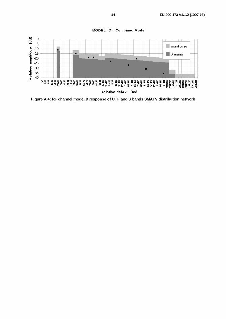
- model D: Combined microreflections model (figure A.4).
Real SMATV networks usually combine features from all models depending on the concrete structure and mainly thecable length and mismatching degree in each connection. It has been concluded that:
- microreflections delay depends on cable lengths;
- microreflections attenuation depends on level of mismatching among components (return losses).
These models are based on assumptions derived from a survey on the most extended SMATV structures(see DVB-TM 1259 in annex D, bibliography).
The following configuration has been considered as a reference:
- a range of 3 m to 3,5 m cable length between cascade user outlets;
- a range of 6 m to 12 m cable length between tap-off and user outlet for parallel structures;
- a range of 10 m to 20 m cable length between head-end amplifiers and first passive elements;
- about 10-storey building, in order to include representative echoes generated in several floors.
In figures A.1 to A.4 microreflection distribution can be observed for the 4 models.
X-axis in the diagrams represent the microreflection delay in ns.
Y-axis gives microreflection attenuation in dB.
Taking the above considerations into account, the echo delay ranges can be noted.
The reference channel model for most practical installations is given in figures A.1 to A.4 marked with "3 sigma" and isrepresented in dark colour.
The upper level refers to the worst case.
A.2 Definition of adaptive equalization requirementsQAM demodulator at the user IRD should include an adaptive equalizer to compensate the channel distortion introducedby SMATV in the UHF band. An equalizer may also be included at the user IRD for QPSK demodulation in the S-band.Equalization should be blind, since the baseline systems do not include any training sequence.Referring to the reference RF channel model of figures A.1 to A.4 for the 3 sigma case, state of the art implementationsof equalizers can provide less than 1 dB implementation margin at a BER of 2 × 10⁻⁴, and less than 100 ms acquisitiontime.

EN 300 473 V1.1.2 (1997-08)13
MODE L A. Microreflections between devices in cons ecutive floors
R elative delay (ns )
-40-35-30-25-20-15-10-50
wors t case
3 s igma...
.. . .
Figure A.1: RF channel model A response of UHF and S bands SMATV distribution network
MODE L B . Microreflections between head-end and 1s t device
R elative delay (ns )
-40-35-30-25-20-15-10-50
wors t case
3 s igma.
Figure A.2: RF channel model B response of UHF and S bands SMATV distribution network
MODE L C. Microreflections between tap-off and us er outlet
R elative delay (ns )
-40-35-30-25-20-15-10-50
wors t case
3 s igma.
Figure A.3: RF channel model C response of UHF and S bands SMATV distribution network
EN 300 473 V1.1.2 (1997-08)14
MODE L D . Combined Model
R elative delay (ns )
-40-35-30-25-20-15-10-50
wors t case
3 s igma...
.. . .
..
Figure A.4: RF channel model D response of UHF and S bands SMATV distribution network

EN 300 473 V1.1.2 (1997-08)15
Annex B (informative):Examples of 64-QAM and QPSK performance withequalizersIn the following, performance of two possible examples of SMATV systems are investigated by computer simulations:
SMATV system A: transmodulation from QPSK to 64-QAM, symbol rate Rs = 6,9 Mbaud in 8 MHz channels,useful bit-rate of 38 Mbit/s at the MPEG multiplex output.
SMATV system B: QPSK modulation with rate 3/4 convolutional coding, symbol rate Rs = 25,8 Mbaud anduseful bit-rate of 35,6 Mbit/s at the MPEG multiplex output.
To overcome the linear distortions introduced by the SMATV network, an adaptive "blind" equalizer(see A. Benveniste, M. Goursat in annex D, bibliography), composed by a symbol-spaced complex transversal filter(FIR), has been introduced in the receiver. The second tap of the equalizer was set to "1", since the presence ofanticipated echoes can generally be excluded in SMATV installations. The results assume steady state of the equalizer,after the end of the blind lock-in phase.
Some critical examples of SMATV channels have been considered in the simulations, as measured on a hardware-simulated SMATV network for a 5-floors building (see G. Garazzino, V. Sardella in annex D, bibliography).The channel amplitude and group delay characteristics are reported in figures B.1 to B.6.The first case (Response - 1) refers to a 40 MHz channel, suitable for system B, while the others(i.e. Response-2, to, Response-6) refer to 8 MHz channels, suitable for system A.
B.1 SMATV System A - Simulation resultsWith system A the signal is re-generated at the SMATV network input, therefore the noise generator in the simulationswas put at the 64-QAM demodulator input, after the SMATV network. Very high degradation levels have been obtainedwithout equalization. In the presence of adaptive equalization with 6 symbol-spaced taps, the signal to noise ratiodegradation for BER equal to 2 × 10⁻⁴ (before Reed-Solomon correction) was lower than 1,5 dB in all the five analysednetwork responses 2. These results refer to the value of 23,8 dB in a bandwidth of 7 MHz in an ideal linear Gaussianchannel; they do not however include possible additional impairments due to amplifier nonlinearity in the cablehead-end.
It is therefore possible to conclude that with SMATV system A (in the 64-QAM configuration) the use of adaptiveequalizers is mandatory to overcome typical SMATV network degradations. However, in the case of old cableinstallations with very poor performance (e.g. echo levels of about 8 dB to 12 dB, as given in annex A,figures A.1 to A.4), the use of the equalizer might be insufficient to guarantee 100 % service availability when64-QAM modulation is adopted. Nevertheless, in the case of new installations complying with EN 50083-3(see annex D, bibliography), the service availability with 64-QAM can be guaranteed by a suitable equalizer.
Hardware tests with a 16-QAM modem including blind equalization have demonstrated good performance on the abovedescribed SMATV network, see ISO/IEC DIS 13818-1 [3].
As regards the required number of equalization (symbol-spaced) taps N, the echo delay spread Te to be considered ontypical SMATV networks is of the order of 220 ns, as indicated in figures A.1 to A.4 (64-QAM requires C/I levels of theorder of 35 dB).Assuming that the second tap of the equalizer is set to "1", to achieve good performance with 64-QAM and high echolevels, N should be larger than 2 + 2Te/Ts.Therefore, for a symbol duration Ts=143 ns, the minimum equalizer length should be of about 6 taps, while 8 to 10 tapscould offer an additional margin to cope with longer echoes.

EN 300 473 V1.1.2 (1997-08)16
B.2 SMATV System B - Simulation resultsSince in a well designed SMATV network, adopting SMATV system B, the main noise source should be in the satellitedown-link path, the noise source in the simulations has been put before the SMATV network.
The SMATV network transfer function, which has been used in the simulations, is "Resp-1" of figure B.1.
For BER equal to 10-4 before Reed-Solomon correction, the SMATV network introduced a degradation on the requiredC/N (calculated in a bandwidth of 26,8 MHz) for the satellite of about 1,4 dB on the system without equalizer, while thedegradation was reduced to 0,4 dB with the equalizer EN 300 421 [2].
These results refer to the value of 6,1 dB in an ideal linear Gaussian channel; no implementation margin is included.Therefore also for method B, based on the rugged QPSK modulation, the use of an adaptive equalizer in the receiverseems important, allowing to utilize current SMATV installations with very low additional C/N degradation with respectto direct satellite reception.
Hardware tests with a QPSK modulator including rate 3/4 convolutional coding, without equalizer, confirmed thesimulation results on the above SMATV network.
As regards the number of equalizer (symbol-spaced) taps N, assuming that the second tap of the equalizer is set to "1",good QPSK performance can be achieved for N > 2 + (Te / Ts), where Te is the echo delay spread to be considered.
For Te = 220 ns, as indicated in figure A.1, and a symbol duration of Ts = 30 ns, the minimum equalizer length shouldbe of about 10 taps.
Amplitude (dB) Group delay (ns)
f-fo (MHz)
-8
-7
-6
-5
-4
-3
-2
-1
0
-20 -15 -10 -5 0 5 10 15 20
-14
-12
-10
-8
-6
-4
-2
0
2
Figure B.1: Response 1: Significant example of the measured transfer function for the consideredSMATV network ( �� amplitude, �� group delay)

EN 300 473 V1.1.2 (1997-08)17
Amplitude (dB) Group delay (ns)
f - fo (MHz)
-4
-3.5
-3
-2.5
-2
-1.5
-1
-0.5
0
-4 -3 -2 -1 0 1 2 3 4
-5
0
5
10
15
20
25
30
35
Figure B.2: Response 2: Significant example of the measured transfer function for the consideredSMATV network ( �� amplitude, �� group delay)
Amplitude (dB) Group delay (ns)
f - fo (MHz)
-4
-3.5
-3
-2.5
-2
-1.5
-1
-0.5
0
-4 -3 -2 -1 0 1 2 3 4
-25
-20
-15
-10
-5
0
5
10
15
Figure B.3: Response 3: Significant example of the measured transfer function for the consideredSMATV network ( �� amplitude, �� group delay)

EN 300 473 V1.1.2 (1997-08)18
Amplitude (dB) Group delay (ns)
f - fo (MHz)
-3
-2.5
-2
-1.5
-1
-0.5
0
-4 -3 -2 -1 0 1 2 3 4
-10
0
10
20
30
40
50
Figure B.4: Response 4: Significant example of the measured transfer function for the consideredSMATV network ( �� amplitude, �� group delay)
Amplitude (dB) Group delay (ns)
f - fo (MHz)
-7
-6
-5
-4
-3
-2
-1
0
-4 -3 -2 -1 0 1 2 3 4
-45
-35
-25
-15
-5
5
15
25
Figure B.5: Response 5: Significant example of the measured transfer function for the consideredSMATV network ( �� amplitude, �� group delay)

EN 300 473 V1.1.2 (1997-08)19
Amplitude (dB) Group delay (ns)
f - fo (MHz)
-9
-8
-7
-6
-5
-4
-3
-2
-1
0
-4 -3 -2 -1 0 1 2 3 4
-65
-55
-45
-35
-25
-15
-5
5
15
25
Figure B.6: Response 6: Significant example of the measured transfer function for the consideredSMATV network ( �� amplitude, �� group delay)

EN 300 473 V1.1.2 (1997-08)20
Annex C (informative):Bit rate consideration for SMATV distribution systemsThis annex is provided only for comparison purposes with respect to similar annex C of EN 300 421 [2], and annex B ofEN 300 429 [1].
In order to achieve a transparent re-transmission of satellite services on SMATV systems, it is necessary to take intoaccount the limitations imposed by the SMATV System in the 8 MHz cable channel bandwidth for SMATV Systemconfigurations.
Table C.1 gives figures, showing the possible ranges of SMATV symbol rates and occupied bandwidths for differentuseful bit rates on the satellite. The 16-QAM, 32-QAM and 64-QAM constellations of the SMATV System A areconsidered.
For full transparency, the same useful bit rate (excluding RS coding) should be used in the satellite and the SMATVcable network.
Referring to annex B of EN 300 429 [1], the theoretical maximum symbol rate in an 8 MHz SMATV channel is6,96 MBaud with a roll-off factor of 0,15. In table C.1 indicative useful bit rates are provided.
Channel bandwidth constraints exist in a number of high loaded SMATV networks, which limit the useful bandwidth to7 MHz. For such existing high loaded networks, transmission of symbol rates about 6 MBaud are feasible withacceptable signal degradation. Symbol rates given above the upper highlighted line support the simplified transparenttransmodulation concept, facilitating the satellite link operation at BER ratios above threshold (before RS) for a givenantenna size. However, future upgrading of current single channel amplifiers may clear such limitations.
Table C.1: Examples of transparent retransmission of satellite TV on SMATV networks using thesame useful bit rate R u (excluding RS)
16 - QAM 32 - QAM 64 - QAMExamples of satellite
Ru for BW (-3dB)/R s=1,27
(after MPEG-2 MUX)
(Mbits)
Symbol rate
(Mbaud)
OccupiedBW
(MHz)
Symbolrate
(Mbaud)
OccupiedBW
(MHz)
Symbolrate
(Mbaud)
OccupiedBW
(MHz)
18,9 5,13 5,90 4,10 4,72 3,42 3,9319,6 5,32 6,11 4,25 4,89 3,54 4,0721,7 5,88 6,77 4,70 5,41 3,92 4,5124,0 6,51 7,49 5,21 5,99 4,34 4,9925,2 6,84 7,86 5,47 6,29 4,56 5,2426,1 5,66 6,51 4,72 5,4326,2 5,68 6,54 4,74 5,4528,3 6,14 7,06 5,12 5,8829,0 6,29 7,24 5,24 6,0329,4 6,38 7,34 5,32 6,1131,5 6,84 7,86 5,70 6,5531,9 6,92 7,96 5,77 6,6332,6 5,89 6,7832,7 5,91 6,8033,1 5,99 6,8833,4 6,04 6,9534,4 6,22 7,1534,8 6,29 7,2435,9 6,49 7,4736,2 6,55 7,5338,1 6,89 7,92
31,672 (PDH) 6,87 7,90 5,73 6,59
NOTE 1:= 7 MHz Cable channel Bandwidth (BW).
NOTE 2:= 8 MHz Cable channel Bandwidth (BW).

EN 300 473 V1.1.2 (1997-08)21
Table C.2 shows the indicative SMATV capacity in case of QPSK channels distributed in the existing extendedsuper-band or in the existing extended IF band for the symbol rates proposed in the satellite EN 300 421 [2].
Other symbol rates and channel spacing are possible.
Table C.2: SMATV-S and SMATV-IF capacity
Number of channelsRs
(Mbaud)
Minimum channelspacing(MHz)
Extended super-band(230 MHz to 470 MHz)
(note)
Satellite first IF band(0,95 GHz to 2,05 GHz)
(note)Total
42,2 57,0 4 19 23
35,9 48,5 4 22 26
31,5 42,5 5 25 30
28,1 37,9 6 28 34
25,8 34,8 6 31 37
23,4 31,6 7 34 41
21,1 28,5 8 38 46
20,3 27,4 8 40 48
NOTE: The frequency ranges in parenthesis are only indicative.Wider ranges may be possible in some circumstances.

EN 300 473 V1.1.2 (1997-08)22
Annex D (Informative):Bibliography
- Reimers, U. NAB'93, document GT V4/MOD 249: "The European perspectives on Digital TelevisionBroadcasting".
- A. Masento, V. Mignone, A. Morello: "Performance of 64-QAM and QPSK in SMATV installations -Simulation results", Report no. 94/xx/E.
- G. Garazzino, V. Sardella: "Preliminary 16-QAM transmission tests in the UHF Band on a SMATV network",RAI Technical Report no. 94/28/I.
- A. Benveniste, M. Goursat, "Blind equalisers", IEEE Trans. Comm., vol.COM-32, pp. 871-883, Aug.1984.
- DVB-TM 1259 (July 1994): "Satellite digital TV in collective antenna systems - SMATV reference channelmodel for digital TV, RACE DIGISMATV Project".
- DTVB 1190/DTVC 38, 3rd revised version, February 1994 (Contribution from DTVC), document:"Specification of modulation, channel coding and framing structure for the Baseline System for digital multi-programme television by cable".
- DTVB 1110/GT V4/MOD 252/ DTVC 18, 7th revised version, January 1994 (Contribution from V4/MOD-B),document: "Specification of the "Baseline modulation/channel coding system" for digital multi-programmetelevision by satellite".
- EN 50083-3: "Cable distribution systems for television and sound signals; Part 3; Active coaxial widebanddistribution equipment".

EN 300 473 V1.1.2 (1997-08)23
History
Document history
Edition 1 May 1995 Publication as ETS 300 473
V1.1.2 August 1997 Publication
ISBN 2-7437-1655-XDépôt légal : Août 1997