enclosed 150 series - dart controls
TRANSCRIPT
ENCL
OSED
150 S
ERIE
S
P.O. Box 105000 W. 106th StreetZionsville, Indiana 46077
Phone (317) 873-5211Fax (317) 873-1105
www.dartcontrols.com
Instruction ManualVariable Speed Control
LT196 (0919)
CONTROLS
A-5-4185A
153D-200E 153D-200E-PB
WARRANTY
Dart Controls, Inc. (DCI) warrants its products to be free from defects in material and workmanship. The exclusive remedy for this warranty is DCI factory replacement of any part or parts of such product which shall within 12 months after delivery to the purchaser be returned to DCI factory with all transportation charges prepaid and which DCI determines to its satisfaction to be defective. This warranty shall not extend to defects in assembly by other than DCI or to any article which has been repaired or altered by other than DCI or to any article which DCI determines has been subjected to improper use. DCI assumes no responsibility for the design characteristics of any unit or its operation in any circuit or assembly. This warranty is in lieu of all other warranties, express or implied; all other liabilities or obligations on the part of DCI, including consequential damages, are hereby expressly excluded.
NOTE: Carefully check the control for shipping damage. Report any damage to the carrier immediately. Do not attempt to operate the drive if visible damage is evident to either the circuit or to the electronic components.
All information contained in this manual is intended to be correct, however information and data in this manual are subject to change without notice. DCI makes no warranty of any kind with regard to this information or data. Further, DCI is not responsible for any omissions or errors or consequential damage caused by the user of the product. DCI reserves the right to make manufacturing changes which may not be included in this manual.
WARNINGImproper installation or operation of this control may cause injury to personnel or control failure. The control must be installed in accordance with local, state, and national safety codes. Make certain that the power supply is disconnected before attempting to service or remove any components!!! If the power disconnect point is out of sight, lock it in disconnected position and tag to prevent unexpected application of power. Only a qualified electrician or service personnel should perform any electrical troubleshooting or maintenance. At no time should circuit continuity be checked by shorting terminals with a screwdriver or other metal device.
AVERTISSEMENTToute installation ou exploitation irrégulière de cette commande peut causer des blessures au personnel ou une panne à la commande. La commande doit être installée en respectant les codes de sécurité locaux, fédéraux et nationaux. Assurez-vous que l’alimentation est coupée avant de maintenir ou d’enlever des composants !!! Si le point de coupure de courant n’est pas visible, bloquez-le à la position de déconnexion et étiquetez-le pour éviter tout mise sous tension imprévue. Toute localisation de panne électrique ou maintenance devrait être effectuée par un électricien qualifié. La continuité du circuit ne devrait en aucun cas être vérifiée en court-circuitant les bornes avec un tournevis ou tout autre objet métallique.
1
TABLE OF CONTENTSWARRANTY ................................................................................................................................................................................ 1WARNING .................................................................................................................................................................................... 1INTRODUCTION ......................................................................................................................................................................... 2CONTROL FEATURES ................................................................................................................................................................ 2150 SERIES HEATSINK DIMENSIONS....................................................................................................................................... 3MOUNTING PROCEDURE .......................................................................................................................................................... 3MODEL SELECTION ................................................................................................................................................................... 3CUSTOMER INSTALLATION, WIRING, & FUSING REQUIREMENTS ...................................................................................... 4TYPICAL MOTOR CURRENTS ................................................................................................................................................... 4150 HOOK-UP DIAGRAM ............................................................................................................................................................ 5SETUP AND WIRING INSTRUCTIONS ....................................................................................................................................... 5CONTROL START-UP ................................................................................................................................................................. 6TRIMPOT ADJUSTMENT PROCEDURE .................................................................................................................................... 7CONTROL HOOK-UP and SETUP MODIFICATIONS ................................................................................................................ 8OPTION DESCRIPTIONS ............................................................................................................................................................ 9
-PB options ............................................................................................................................................................................ 9-29B option ......................................................................................................................................................................... 10-56H3 option ....................................................................................................................................................................... 11
IN CASE OF DIFFICULTY ......................................................................................................................................................... 12SPECIFICATIONS ...................................................................................................................................................................... 12
INTRODUCTION • The 150 series enclosed controls are to be used with DC motors from 1/50 - 1 HP (90VDC) and 1/25 - 2 HP (180VDC)
• The 150 series models are available for dual voltage input requirements of 120/240 Vac. Dual voltage models, via jumper setting, will output 90Vdc (using 120 or 240Vac supply) or 180Vdc (240Vac supply only)
• Model selections are available in two feature sets. The full featured 150D models include adjustable Accel & Decel, LED indicators for Power ON & Current Limit, and a wide range of available options. The 150L models are built for cost sensitive applications and OEM specials.
• The control is designed to operate DC Permanent Magnet, Shunt Wound (150D models only), and some Universal (AC/DC) motors in the above horsepower ranges.
• Incoming AC voltage is converted to adjustable full wave rectified DC voltage to operate the DC motor. Also, a full wave field voltage is provided for shunt wound motors on the 150D models. • All models incorporate transient voltage protection, adjustable current limit, adjustable minimum and maximum speeds, adjustable IR compensation and an inhibit function.
• All models come standard with fixed terminal blocks.
• Digital display with push button potentiometer and manual reversing models are available
CONTROL FEATURESMIN SPEED (Minimum Speed) - Allows adjustment of the motor speed when the speedpot is set at minimum (CCW). This permits the user to eliminate "Deadband" on the main speed control, for zero calibration. Clockwise rotation of "MIN" trimpot increases speed.
MAX SPEED (Maximum Speed) - Allows the user to set the maximum output voltage and speed required for the application with the speedpot at maximum rotation. Rotation of the "MAX" trimpot in the clockwise direction increases the maximum motor speed.
IR COMP (Speed Regulation) - This allows for adjustment of the output voltage gain needed to overcome speed losses during increased motor load. The circuitry controls armature speed by changing the armature voltage to compensate for increased or decreased motor loading. Clockwise rotation of the "IR COMP" trimpot will increase gain compensation.
CUR. LIM. (Current Limit) - Provides protection from excessive armature current by limiting the maximum continuous armature current the control can provide. Current Limit should be set at 125% of rated motor torque (current) based on horsepower. Clockwise rotation of the "CUR. LIM." trimpot increases the current that the control will provide.
INHIBIT TERMINAL PINS - Allows the user to (hard) quickly stop and start the control output via a SPST switch. Using the inhibit inputs will bypass Accel and Decel ramps.
ACCEL & DECEL – 150D models have adjustable accel and decel with a setting range of 0.5-8 seconds for accel and 0.5-6 seconds for decel. CW rotation increases the accel and decel ramp times. The 150L models come with fixed 0.5 second accel and decel.
INPUT & OUTPUT SELECTION PINS – All 153D and 153L models come standard with selectable input voltage pins for 120 or 240 Vac operation, and selectable output voltage pins for 90 or 180 Vdc motors. NOTE: 90Vdc outputs can be achieved from 120 or 240Vac inputs however a 180Vdc output can only be achieved from a 240Vac input supply.
POWER ON & INDICATOR – On 150 Enclosed models with optional -PB digital display.
TRANSIENT PROTECTION – All models come with MOV and X2 rated line capacitors for transient and noise protection.
2
3
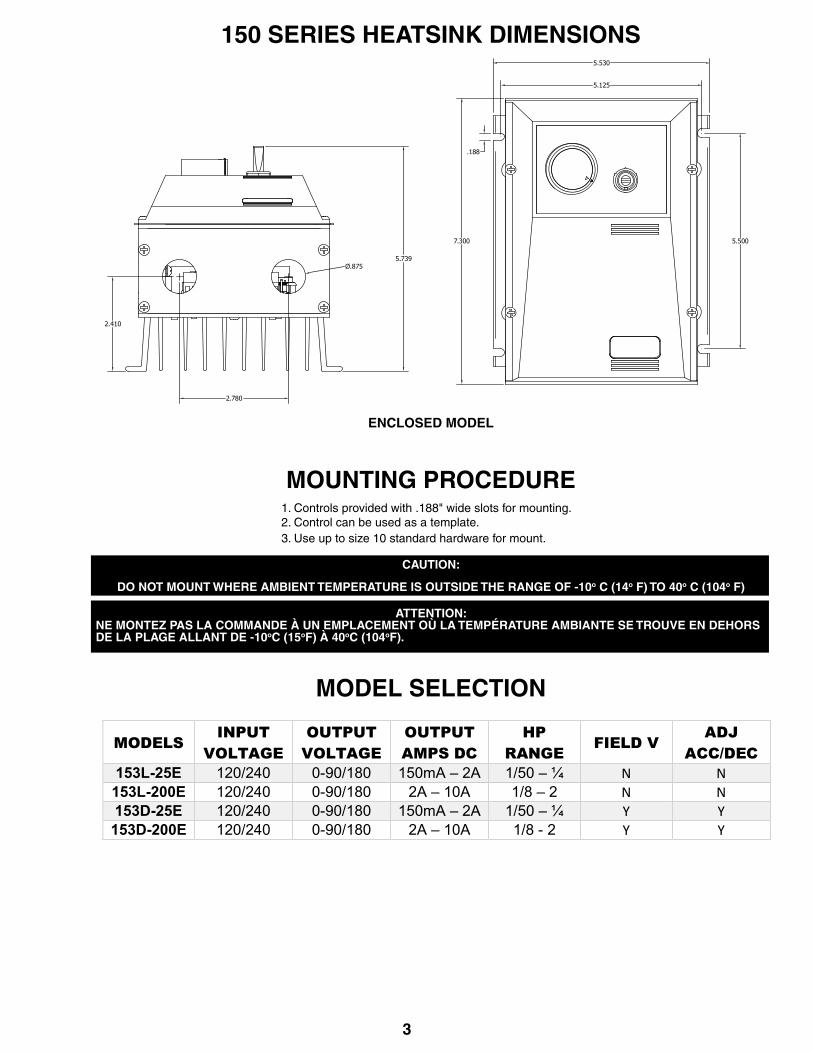
ENCLOSED MODEL
150 SERIES HEATSINK DIMENSIONS
MOUNTING PROCEDURE 1. Controls provided with .188" wide slots for mounting. 2. Control can be used as a template. 3. Use up to size 10 standard hardware for mount.
CAUTION:
DO NOT MOUNT WHERE AMBIENT TEMPERATURE IS OUTSIDE THE RANGE OF -10o C (14o F) TO 40o C (104o F) ATTENTION:
NE MONTEZ PAS LA COMMANDE À UN EMPLACEMENT OÙ LA TEMPÉRATURE AMBIANTE SE TROUVE EN DEHORS DE LA PLAGE ALLANT DE -10oC (15oF) À 40oC (104oF).
MODEL SELECTION
MODELS INPUT
VOLTAGE OUTPUT
VOLTAGE OUTPUT AMPS DC
HP RANGE
FIELD V ADJ
ACC/DEC 153L-25E 120/240 0-90/180 150mA – 2A 1/50 – ¼ N N 153L-200E 120/240 0-90/180 2A – 10A 1/8 – 2 N N 153D-25E 120/240 0-90/180 150mA – 2A 1/50 – ¼ Y Y 153D-200E 120/240 0-90/180 2A – 10A 1/8 - 2 Y Y
5.500
5.125
5.530
.188
7.300
5.739
2.410
2.780
Ø.875
4
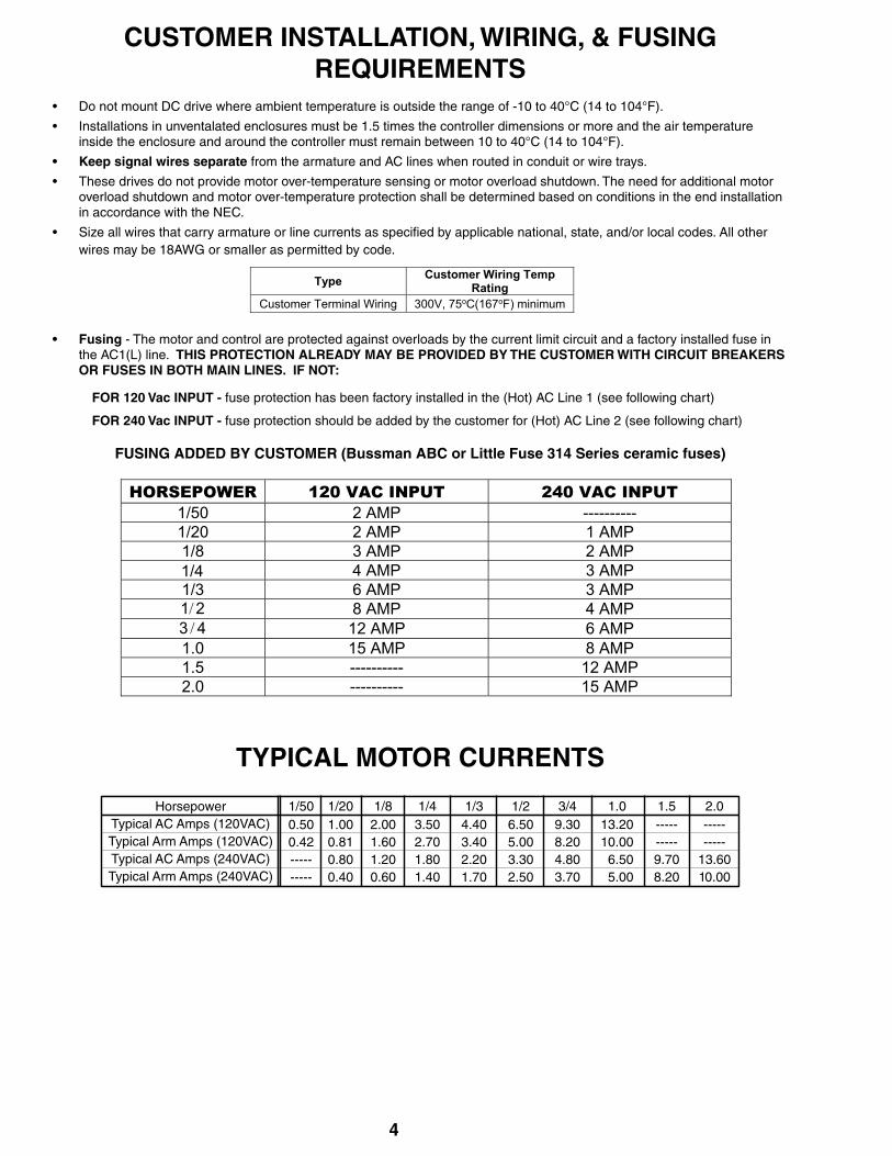
CUSTOMER INSTALLATION, WIRING, & FUSINGREQUIREMENTS
• Do not mount DC drive where ambient temperature is outside the range of -10 to 40°C (14 to 104°F).
• Installations in unventalated enclosures must be 1.5 times the controller dimensions or more and the air temperature inside the enclosure and around the controller must remain between 10 to 40°C (14 to 104°F).
• Keep signal wires separate from the armature and AC lines when routed in conduit or wire trays.
• These drives do not provide motor over-temperature sensing or motor overload shutdown. The need for additional motor overload shutdown and motor over-temperature protection shall be determined based on conditions in the end installation in accordance with the NEC.
• Size all wires that carry armature or line currents as specified by applicable national, state, and/or local codes. All other wires may be 18AWG or smaller as permitted by code.
Type Customer Wiring Temp Rating
Customer Terminal Wiring 300V, 75oC(167oF) minimum
• Fusing - The motor and control are protected against overloads by the current limit circuit and a factory installed fuse in the AC1(L) line. THIS PROTECTION ALREADY MAY BE PROVIDED BY THE CUSTOMER WITH CIRCUIT BREAKERS OR FUSES IN BOTH MAIN LINES. IF NOT:
FOR 120 Vac INPUT - fuse protection has been factory installed in the (Hot) AC Line 1 (see following chart)
FOR 240 Vac INPUT - fuse protection should be added by the customer for (Hot) AC Line 2 (see following chart)
FUSING ADDED BY CUSTOMER (Bussman ABC or Little Fuse 314 Series ceramic fuses)
HORSEPOWER 120 VAC INPUT 240 VAC INPUT 1/50 2 AMP ---------- 1/20 2 AMP 1 AMP 1/8 3 AMP 2 AMP 1/4 4 AMP 3 AMP 1/3 6 AMP 3 AMP
21/ 8 AMP 4 AMP 43 / 12 AMP 6 AMP
1.0 15 AMP 8 AMP 1.5 ---------- 12 AMP 2.0 ---------- 15 AMP
TYPICAL MOTOR CURRENTS
0.500.42----------
1.000.810.800.40
2.001.601.200.60
3.502.701.801.40
1/50 1/20 1/8 1/4HorsepowerTypical AC Amps (120VAC)Typical Arm Amps (120VAC)Typical AC Amps (240VAC)Typical Arm Amps (240VAC)
4.403.402.201.70
1/36.505.003.302.50
1/29.308.204.803.70
3/413.2010.006.505.00
1.0----------9.708.20
1.5----------
13.6010.00
2.0
5
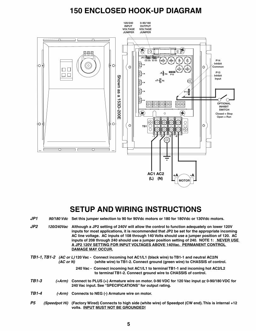
150 ENCLOSED HOOK-UP DIAGRAM
SETUP AND WIRING INSTRUCTIONSJP1 90/180 Vdc Set this jumper selection to 90 for 90Vdc motors or 180 for 180Vdc or 130Vdc motors.
JP2 120/240Vac Although a JP2 setting of 240V will allow the control to function adequately on lower 120V inputs for most applications, it is recommended that JP2 be set for the appropriate incoming AC line voltage. AC inputs of 108 through 140 Volts should use a jumper position of 120. AC inputs of 208 through 240 should use a jumper position setting of 240. NOTE 1: NEVER USE A JP2 120V SETTING FOR INPUT VOLTAGES ABOVE 140Vac. PERMANENT CONTROL DAMAGE MAY OCCUR.
TB1-1, TB1-2 (AC or L) 120 Vac - Connect incoming hot AC1/L1 (black wire) to TB1-1 and neutral AC2/N (AC or N) (white wire) to TB1-2. Connect ground (green wire) to CHASSIS of control.
240 Vac - Connect incoming hot AC1/L1 to terminal TB1-1 and incoming hot AC2/L2 to terminal TB1-2. Connect ground wire to CHASSIS of control.
TB1-3 (+Arm) Connect to PLUS (+) Armature wire on motor. 0-90 VDC for 120 Vac input or 0-90/180 VDC for 240 Vac input. See “SPECIFICATIONS” for output rating.
TB1-4 (-Arm) Connects to NEG (-) Armature wire on motor.
P5 (Speedpot Hi) (Factory Wired) Connects to high side (white wire) of Speedpot (CW end). This is internal +12 volts. INPUT MUST NOT BE GROUNDED!
JP1JP2 } } } }
18090240120
+A -AAC1(L)
AC2(N)
P13InhibitInput
OPTIONAL INHIBIT SWITCH
P14Inhibit
Common
Closed = StopOpen = Run
120/240 INPUT
VOLTAGEJUMPER
0-90/180OUTPUTVOLTAGEJUMPER
MOTOR
TB1
-1 -4-2 -3
P11
CLIRMINMAX
DECACC
P8
P9 P10-F
+F
Sho
wn as a 153D
-200E

6
P6 (Speedpot Wiper) (Factory Wired) Connects to wiper (red wire) of Speedpot (center lead). For Start-Stop applications requiring soft start and soft stop (Accel and Decel ramps), the connection between this terminal and Speedpot Wiper can be opened and closed by a SPST switch. For Voltage Follower applications, this INPUT MUST NOT BE GREATER THAN +12V MAXIMUM AND MUST NOT BE GROUNDED!
P7 (Speedpot Lo) (Factory Wired) Connects to Low side (orange wire) of Speedpot (CCW end). This input is raised and lowered by the MIN trimpot. Electronic speed input (voltage follower) may be referenced to Speedpot LO if the MIN trimpot adjustments are to be active. Otherwise, inputs may be referenced to -ARM, which will bypass the MIN trimpot. INPUT MUST NOT BE GROUNDED!
P8 (+Field) DO NOT use for Permanent Magnet Motor. This supplies +Field voltage for a SHUNT WOUND (150D Models ONLY) MOTOR. For motors with dual voltage field (ie. 50/100V or 100/200V), make certain highest value is connected.
P9 (-Field) Connects to Negative (-) Field wire of a SHUNT WOUND MOTOR. This connection is also circuit (150D Models ONLY) common but must never be connected to earth or chassis gnd. Doing so will result in damage to the control.
P13 (Inhibit Input) Connecting this input to the Inhibit Common pin will result in a fast stop. Opening this connection will result in a quick acceleration of the motor to the wiper input set point. Stopping and starting via the Inhibit pins bypasses all accel and decel ramps.
P14 (Inhibit Connecting this input to the Inhibit pin willl result in a fast stop. Opening this connection Common) will result in a quick acceleration of the motor to the wiper input set point. Stopping and starting via the Inhibit pins bypasses all accel and decel ramps.
Warning:1. Be sure the control housing is properly grounded.2. Armature connections must not be switched or broken while the control is on. Serious control damage may result.3. For non-speedpot applications, the input connection to the LO, WIPER, and HI terminals must not be grounded! Serious control damage may result from a grounded input.
Avertissement 1. Assurez-vous que le coffrage du système de commande est correctement mis à la terre. 2. Les raccordements ARM ne doivent pas être commutés ou interrompus pendant que la commande est sazous ten sion. De sérieux dégâts peuvent en découler. 3. Pour les applications sans potentiomètre : les connexions d’entrée vers les fils Lo-Curseur-Hi ne doivent pas être mises à la terre. Une entrée mise à la terre peut gravement endommager la commande.
Warning:Do not attempt to perform Hi-pot test across AC lines with control in circuit.
This will result in immediate or long term damage to the control.
Avertissement: N’essayez pas d’effectuer d’essai diélectrique à travers les lignes CA lorsque la commande est dans le circuit. La commande sera immédiatement et irrémédiablement endommagée.
CONTROL START-UP
WARNING: ALL POWER MUST BE TURNED OFF BEFORE PROCEEDING!
AVERTISSEMENT : L’ALIMENTATION DOIT ÊTRE COUPÉE AVANT DE DÉMARRER !!!
1. Recheck all wiring. Accidental grounds cause by, loose or pinched wires on the armature or speedpot may damage the control when power is applied.2. Check to see that incoming service is of correct voltage.3. Check to make sure the input line voltage jumper selection (JP2) is set to the correct incoming service.4. Check to make sure the 90/180 volt motor jumper selection (JP1) is set to the correct armature motor voltage required.5. Turn speedpot to zero (fully CCW).6. Turn power on, and advance speedpot while observing motor rotation. If motor rotation is correct, proceed to step 8. Power must be off before step 7 can be accomplished! 7. If motor rotation is incorrect, turn power off at external disconnect and reverse +ARM and -ARM connections. 8. Check for satisfactory operation throughout the speed range.9. If operation is satisfactory, no readjustments are needed.10. If additional control tuning and setup are needed, see the following "TRIMPOT ADJUSTMENT PROCEDURE".11. For other problems, consult section, “IN CASE OF DIFFICULTY”.
7
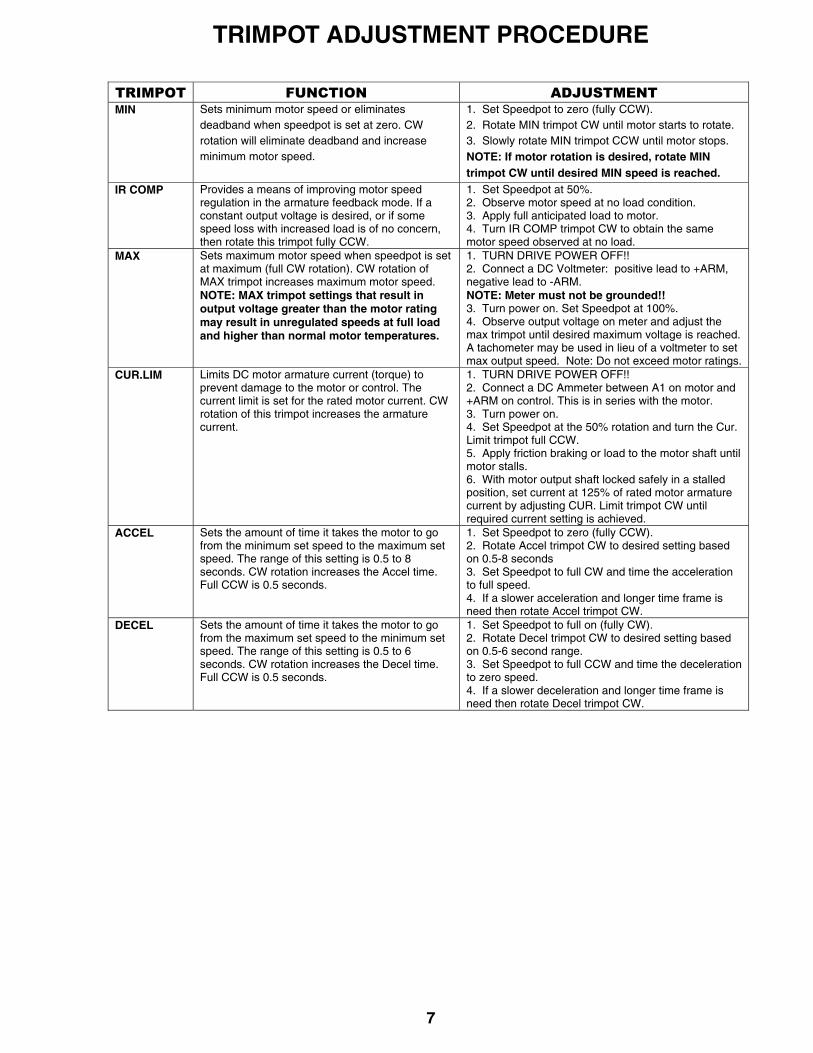
TRIMPOT ADJUSTMENT PROCEDURE
TRIMPOT FUNCTION ADJUSTMENT MIN Sets minimum motor speed or eliminates
deadband when speedpot is set at zero. CW rotation will eliminate deadband and increase minimum motor speed.
1. Set Speedpot to zero (fully CCW). 2. Rotate MIN trimpot CW until motor starts to rotate. 3. Slowly rotate MIN trimpot CCW until motor stops. NOTE: If motor rotation is desired, rotate MIN trimpot CW until desired MIN speed is reached.
IR COMP
Provides a means of improving motor speed regulation in the armature feedback mode. If a constant output voltage is desired, or if some speed loss with increased load is of no concern, then rotate this trimpot fully CCW.
1. Set Speedpot at 50%. 2. Observe motor speed at no load condition. 3. Apply full anticipated load to motor. 4. Turn IR COMP trimpot CW to obtain the same motor speed observed at no load.
MAX
Sets maximum motor speed when speedpot is set at maximum (full CW rotation). CW rotation of MAX trimpot increases maximum motor speed. NOTE: MAX trimpot settings that result in output voltage greater than the motor rating may result in unregulated speeds at full load and higher than normal motor temperatures.
1. TURN DRIVE POWER OFF!! 2. Connect a DC Voltmeter: positive lead to +ARM, negative lead to -ARM. NOTE: Meter must not be grounded!! 3. Turn power on. Set Speedpot at 100%. 4. Observe output voltage on meter and adjust the max trimpot until desired maximum voltage is reached. A tachometer may be used in lieu of a voltmeter to set max output speed. Note: Do not exceed motor ratings.
CUR.LIM Limits DC motor armature current (torque) to prevent damage to the motor or control. The current limit is set for the rated motor current. CW rotation of this trimpot increases the armature current.
1. TURN DRIVE POWER OFF!! 2. Connect a DC Ammeter between A1 on motor and +ARM on control. This is in series with the motor. 3. Turn power on. 4. Set Speedpot at the 50% rotation and turn the Cur. Limit trimpot full CCW. 5. Apply friction braking or load to the motor shaft until motor stalls. 6. With motor output shaft locked safely in a stalled position, set current at 125% of rated motor armature current by adjusting CUR. Limit trimpot CW until required current setting is achieved.
ACCEL Sets the amount of time it takes the motor to go from the minimum set speed to the maximum set speed. The range of this setting is 0.5 to 8 seconds. CW rotation increases the Accel time. Full CCW is 0.5 seconds.
1. Set Speedpot to zero (fully CCW). 2. Rotate Accel trimpot CW to desired setting based on 0.5-8 seconds 3. Set Speedpot to full CW and time the acceleration to full speed. 4. If a slower acceleration and longer time frame is need then rotate Accel trimpot CW.
DECEL Sets the amount of time it takes the motor to go from the maximum set speed to the minimum set speed. The range of this setting is 0.5 to 6 seconds. CW rotation increases the Decel time. Full CCW is 0.5 seconds.
1. Set Speedpot to full on (fully CW). 2. Rotate Decel trimpot CW to desired setting based on 0.5-6 second range. 3. Set Speedpot to full CCW and time the deceleration to zero speed. 4. If a slower deceleration and longer time frame is need then rotate Decel trimpot CW.
8
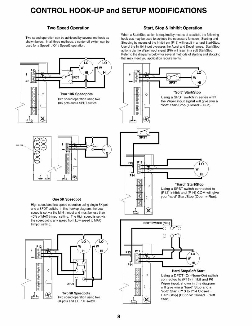
CONTROL HOOK-UP and SETUP MODIFICATIONS
Two speed operation can be achieved by several methods as shown below. In all three methods, a center off switch can be used for a Speed1 / Off / Speed2 operation.
Two Speed Operation
WHI
LOW
HI
LO
HISPDT
Two 10K SpeedpotsTwo speed operation using two 10K pots and a SPDT switch.
SPDT
Two 5K Speedpots
WHI
LO
DPDT
HIW
HI
LOW
LO
HI
High speed and low speed operation using single 5K potand a SPDT switch. In this hookup diagram, the Lowspeed is set via the MIN trimpot and must be less than40% of MAX trimpot setting. The High speed is set viathe speedpot to any speed from Low speed to MAXtrimpot setting.
Two speed operation using two 5K pots and a DPDT switch.
When a Start/Stop action is required by means of a switch, the following hook-ups may be used to achieve the necessary function. Starting and Stopping by means of the Inhibit pin (P13) will result in a hard Start/Stop.Use of the Inhibit input bypasses the Accel and Decel ramps. Start/Stop actions via the Wiper input signal (P6) will result in a soft Start/Stop. Refer to the diagrams below for several methods of starting and stoppingthat may meet you application requirements.
Start, Stop & Inhibit Operation
Using a SPST switch in series witht the Wiper input signal will give you a “soft” Start/Stop (Closed = Run).
Using a SPST switch connected to (P13) inhibit and (P14) COM will give you “hard” Start/Stop (Open = Run).
Using a DPDT (On-None-On) switch connected to (P13) inhibit and P6 Wiper input, shown in this diagram will give you a “hard” Stop and a “soft” Start (P13 to P14 Closed = Hard Stop) (P6 to W Closed = Soft Start).
SPSTW
HI
LO
SPST
WHI
LO
DPDT SWITCH (N.C.)
WHI
LO
One 5K Speedpot
“Soft” Start/Stop
“Hard” Start/Stop
Hard Stop/Soft Start
P13
P14
P13
P14
P12
P12
P12
P12
P12
P12
MIN POT
OPTION DESCRIPTIONS
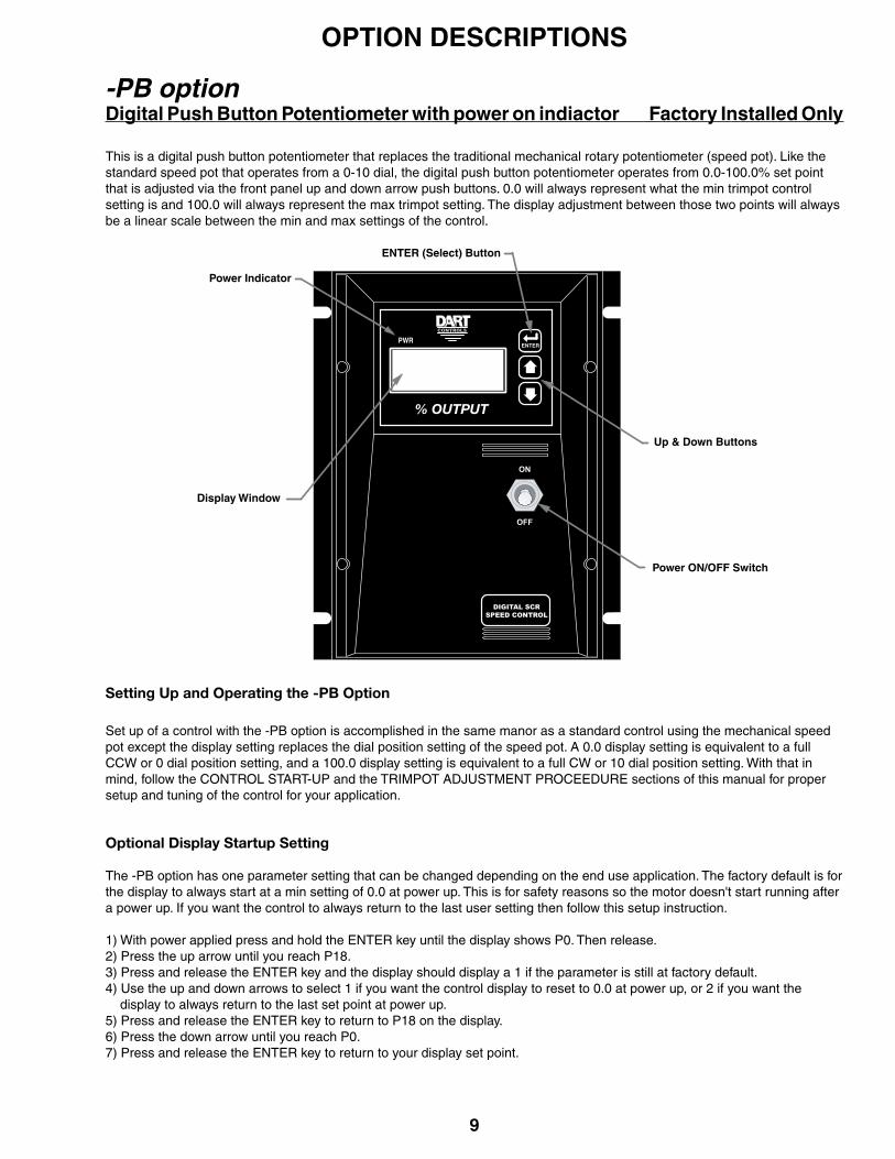
-PB option Digital Push Button Potentiometer with power on indiactor Factory Installed Only
This is a digital push button potentiometer that replaces the traditional mechanical rotary potentiometer (speed pot). Like the standard speed pot that operates from a 0-10 dial, the digital push button potentiometer operates from 0.0-100.0% set point that is adjusted via the front panel up and down arrow push buttons. 0.0 will always represent what the min trimpot control setting is and 100.0 will always represent the max trimpot setting. The display adjustment between those two points will always be a linear scale between the min and max settings of the control.
Setting Up and Operating the -PB Option
Set up of a control with the -PB option is accomplished in the same manor as a standard control using the mechanical speed pot except the display setting replaces the dial position setting of the speed pot. A 0.0 display setting is equivalent to a full CCW or 0 dial position setting, and a 100.0 display setting is equivalent to a full CW or 10 dial position setting. With that in mind, follow the CONTROL START-UP and the TRIMPOT ADJUSTMENT PROCEEDURE sections of this manual for proper setup and tuning of the control for your application.
Optional Display Startup Setting
The -PB option has one parameter setting that can be changed depending on the end use application. The factory default is for the display to always start at a min setting of 0.0 at power up. This is for safety reasons so the motor doesn't start running after a power up. If you want the control to always return to the last user setting then follow this setup instruction.
1) With power applied press and hold the ENTER key until the display shows P0. Then release.2) Press the up arrow until you reach P18.3) Press and release the ENTER key and the display should display a 1 if the parameter is still at factory default. 4) Use the up and down arrows to select 1 if you want the control display to reset to 0.0 at power up, or 2 if you want the display to always return to the last set point at power up. 5) Press and release the ENTER key to return to P18 on the display. 6) Press the down arrow until you reach P0.7) Press and release the ENTER key to return to your display set point.
9
CONTROLS
ENTERPWR
% OUTPUT
DIGITAL SCR SPEED CONTROL
ON
OFF
Up & Down Buttons
ENTER (Select) Button
Display Window
Power ON/OFF Switch
Power Indicator
10
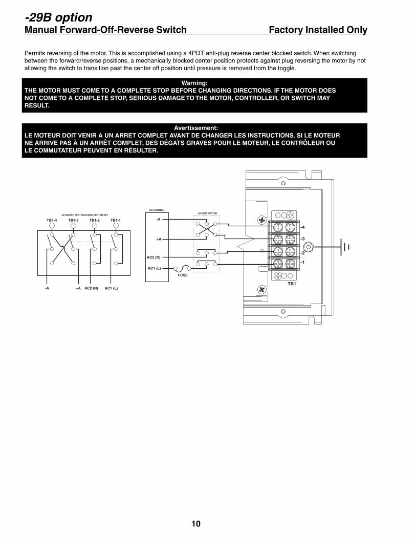
-29B option Manual Forward-Off-Reverse Switch Factory Installed Only
Permits reversing of the motor. This is accomplished using a 4PDT anti-plug reverse center blocked switch. When switching between the forward/reverse positions, a mechanically blocked center position protects against plug reversing the motor by not allowing the switch to transition past the center off position until pressure is removed from the toggle.
Warning:THE MOTOR MUST COME TO A COMPLETE STOP BEFORE CHANGING DIRECTIONS. IF THE MOTOR DOES NOT COME TO A COMPLETE STOP, SERIOUS DAMAGE TO THE MOTOR, CONTROLLER, OR SWITCH MAY RESULT.
Avertissement: LE MOTEUR DOIT VENIR A UN ARRET COMPLET AVANT DE CHANGER LES INSTRUCTIONS. SI LE MOTEUR NE ARRIVE PAS À UN ARRÊT COMPLET, DES DÉGATS GRAVES POUR LE MOTEUR, LE CONTRÔLEUR OU LE COMMUTATEUR PEUVENT EN RÉSULTER.
-A
+A
AC2 (N)
AC1 (L)
TB1-4 TB1-3 TB1-2 TB1-1
-A +A
AC1 (L)AC2 (N)TB1
-1
-2
-3
-4
-29 4PDT SWITCH150 CONTROL
-29 SWITCH 4PDT BLOCKED CENTER OFF
FUSE

11
-56H3 option Isolated Signal Input with Auto/Manual Hook-Up Factory Installed
NOTE 1: This option is factory installed only.NOTE 2: Use of this option eliminates the availability of the + and – field pins for use with DC Shunt Wound Motors.NOTE 3: This option changes the function of the cover switch to 'Auto-Off-Manual', where Auto is following input signal for motor speed, Off is AC power off to the control, and Manual is motor speed set by pot / digi-pot in cover.
This option card allows for the use of either a grounded or non-grounded remote DC signal such as 0 to 5 through 0 to 250Vdc, 4-20mA current, or a remote speed pot. The DC input signal type can be selected for voltage (Vin) or current (4-20mA) via the JP2 jumper clip. There is a Hi/Lo range jumper selection that should be set to the (Lo) setting when using a 4-20mA signal, or voltage ranges of 0-5 through 0-25Vdc. When using voltage ranges of 0-25 through 0-250 this jumper must be set to (Hi). The GAIN trimpot is used to set full linear output in reference to the input signal range. The output of this remote signal isolation board is a linear signal that is proportional to the remote input signal being supplied.
CAUTION: DO NOT use TRIMPOT ADJUSTMENT CHART. Set pots using directions in the previous SET-UP PROCEDURE.
SETUP PROCEDURE FOR -56H3 OPTION1. With NO power to control, connect a DC Voltmeter to control the output as follows: Meter COMMON to the -ARM terminal, and meter POSITIVE to the +ARM terminal. Select correct meter range (for 90Vdc or 180Vdc if needed).2. Preset GAIN pot on the remote signal board fully CCW. 3. Place the JP2 jumper clip in the proper position based on the input signal being used.4. Place the P4 jumper clip in the (LO) position for 4-20mA signals or voltage signals less than 25Vdc. Place the P4 jumper clip in the (HI) position for voltage signals greater than 25Vdc. (NOTE: Never exceed input signals greater than 250Vdc)5. Make sure all connections and jumper settings are properly made per the hookup connection diagram and then apply AC power to the controller.6. Set the remote input signal to its lowest setting. Adjust the MIN trimpot to deadband (the point just before an increase causes an output).7. Apply the maximum remote input signal. Motor should start to run. Adjust the GAIN pot CW until no further increase in con-trol output voltage occurs and then decrease the gain pot slowly until output voltage to the motor drops approximately 5Vdc.8. Set the MAX trimpot on the control to the correct motor voltage.9. Some interaction between trimpots may occur. Recheck the Min trimpot setting and repeat steps 6 through 8 as needed.
CU
STO
ME
R W
IRIN
G
GROUND
SIGNAL
AC2(N)
AC1(L)
- ARM
+ ARM
+
-
COM
+5V
SIG
HI
Vin 4-20
GAIN POT
INPUT TYPE
SELECTOR(Vin OR 4-20in)
VOLTAGERANGE
JUMPERCONNECTOR
LO
120/240 INPUT
VOLTAGEJUMPER
0-90/180OUTPUT
VOLTAGEJUMPER
JP2
JP1

12
IN CASE OF DIFFICULTY
PROBLEM POSSIBLE CAUSE(S) CORRECTIVE ACTION(S)Motor doesn’t operate - Blown Fuse or Breaker
- Incorrect or no power source- Speedpot set at zero- Worn motor brushes
Replace Fuse or reset breakerInstall proper serviceAdjust Speedpot CW to startReplace brushes
Armature output voltagecannot be adjusted, outputis a constant DC level
Motor stalls, or runs veryslowly with speed controlturned fully CW
- No motor or load connected
- Speedpot low connection open
- Low Voltage- Overload Condition
- Worn motor brushes- MAX SPEED set incorrectly
Check that motor or load is connected toarmature terminalsCheck that speedpot low wire is connected
Check that Vac is above 100VacReduce load or increase motor size and/orCur. Lim. setting.Replace brushesSee ADJUSTMENT PROCEDURE
Motor hunts - Motor current less than 150mA
- Too much IR COMP- Motor is in current limit- Motor speed is above rated speed- Max set too high
Motor current must be greater than 150mAD.C.See ADJUSTMENT PROCEDURESee ADJUSTMENT PROCEDUREReduce SpeedSee ADJUSTMENT PROCEDURE
Repeated fuse blowing - Low Voltage- Overload Condition- Worn motor brushes- Defective motor bearings- Defective electrical components
Check that VAC is above 100VacReduce loadReplaceReplaceCall Dart Distributor or Representative
SPECIFICATIONS
AC input voltage .................................................................................................................................. 120 or 240 Vac +10V/-12VAcceleration ............................................................................................................................... (150L Models) 0.5 seconds fixed (150D Models) 0.5 - 8 seconds adjustableAmps - DC output ............................................................................................................................................... 150mA to 10AdcController overload capacity ......................................................................................................................... 200% for one minuteCurrent limit trimpot range ............................................................................. (150 Models followed by -12C/-25C) 0.3 to 2.5Adc (150 Models followed by -100C/-200C) 1 to 15AdcDeceleration .............................................................................................................................. (150L Models) 0.5 seconds fixed (150D Models) 0.5 - 6 seconds adjustableDimensions and weights:
ENGLISHMETRIC
5.530"140.4mm
7.300"185.4mm
5.739"145.8mm
3.005 lb.1363 gms.
WIDTH LENGTH DEPTH WEIGHT3.120 lb.1415 gms.
WEIGHT (-PB)
Drive service factor ................................................................................................................................................................... 1.0Efficiency ..................................................................................................................................................................... 85% typicalInput frequency ....................................................................................................................................................... 50 or 60 HertzMax. trimpot speed range ................................................................................................................. 60% to 110% of base speedMin. trimpot speed range .............................................................................................................. 0% to 30% of maximum speedPower devices ............................................................................................................................................ SCR isolated case tabShunt field voltage .................. (Available on 150D Models only) 100Vdc @ 120Vac input; 200Vdc @ 240Vac input; .7Adc MAXSpeed control ....................................................................................... via 5kW 1/2W potentiometer or 0-10Vdc isolated signalSpeed range ........................................................................................................................................................................... 30:1Speed regulation ............................................................................................................................................ ±1% of base speedTemperature range ............................................................................................................. -10o to 40o C. ambient (15o to 104o F.)Transient protection ................................................................................................................... MOV and X2 rated line capacitorTrigger ........................................................................................................................................................................ opto-couplerType of accel/decel ramp ...................................................................................................................... 150D models only - linear

13
NOTES:

14
NOTES:
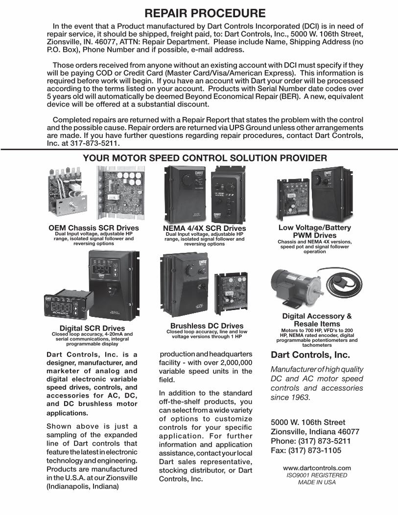
In the event that a Product manufactured by Dart Controls Incorporated (DCI) is in need of repair service, it should be shipped, freight paid, to: Dart Controls, Inc., 5000 W. 106th Street, Zionsville, IN. 46077, ATTN: Repair Department. Please include Name, Shipping Address (no P.O. Box), Phone Number and if possible, e-mail address.
Those orders received from anyone without an existing account with DCI must specify if they will be paying COD or Credit Card (Master Card/Visa/American Express). This information is required before work will begin. If you have an account with Dart your order will be processed according to the terms listed on your account. Products with Serial Number date codes over 5 years old will automatically be deemed Beyond Economical Repair (BER). A new, equivalent device will be offered at a substantial discount.
Completed repairs are returned with a Repair Report that states the problem with the control and the possible cause. Repair orders are returned via UPS Ground unless other arrangements are made. If you have further questions regarding repair procedures, contact Dart Controls, Inc. at 317-873-5211.
REPAIR PROCEDURE
Dart Controls, Inc.
Manufacturer of high quality DC and AC motor speed controls and accessories since 1963.
5000 W. 106th StreetZionsville, Indiana 46077Phone: (317) 873-5211Fax: (317) 873-1105
www.dartcontrols.comISO9001 REGISTERED
MADE IN USA
production and headquarters facility - with over 2,000,000 variable speed units in the field.
In addition to the standard off-the-shelf products, you can select from a wide variety of options to customize controls for your specific application. For further information and application assistance, contact your local Dart sales representative, stocking distributor, or Dart Controls, Inc.
Dart Controls, Inc. is a designer, manufacturer, and marketer of analog and digital electronic variable speed drives, controls, and accessories for AC, DC, and DC brushless motor applications.
Shown above is just a sampling of the expanded line of Dart controls that feature the latest in electronic technology and engineering. Products are manufactured in the U.S.A. at our Zionsville (Indianapolis, Indiana)
YOUR MOTOR SPEED CONTROL SOLUTION PROVIDER
Digital SCR DrivesClosed loop accuracy, 4-20mA and
serial communications, integral programmable display
NEMA 4/4X SCR DrivesDual Input voltage, adjustable HP range, isolated signal follower and
reversing options
Low Voltage/BatteryPWM Drives
Chassis and NEMA 4X versions, speed pot and signal follower
operation
Digital Accessory & Resale Items
Motors to 700 HP, VFD's to 200 HP, NEMA rated encoder, digital
programmable potentiometers and tachometers
Brushless DC DrivesClosed loop accuracy, line and low
voltage versions through 1 HP
OEM Chassis SCR DrivesDual Input voltage, adjustable HP range, isolated signal follower and
reversing options