endoscopic orbital surgery
TRANSCRIPT

Atlas Oral Maxillofacial Surg Clin N Am 11 (2003) 179–208
Endoscopic orbital surgery
Chien-Tzung Chen, MDa,*, Yu-Ray Chen, MDb
aDivision of Plastic Surgery, Department of Trauma and Emergency Surgery, Chang Gung Memorial Hospital,
Chang Gung University, 5, Fu-Shing Street, Kweishan, 333 Taoyuan, TaiwanbDepartment of Plastic & Reconstructive Surgery, Chang Gung Memorial Hospital, Chang Gung University,
5, Fu-Shing Street, Kweishan, 333 Taoyuan, Taiwan
In the early 1990s, endoscopy was introduced into the plastic surgery community. Theapplication of the endoscope in forehead lifting without conventional coronal incision was firstintroduced to the field. The endoscopic procedure was rapidly expanded to midface and totalfacelifts. Benefits have included more aesthetic location of the incisions, smaller scars, improvedhemostasis, preservation of the innervation with magnified visualization, and shorterconvalescence period. At present, endoscopy is a widely accepted procedure in aestheticsurgery of the face. Although the use of the endoscope in facial aesthetics was among the firstideas and techniques described in the plastic surgical field, its application to reconstructivesurgery of the face and facial fracture repair lagged behind.
Conventional access to the middle and upper thirds of the facial skeleton for the repair offacial fractures and for facial reconstructive surgery has involved a combination of coronal,lower eyelid, upper buccal sulcus, and preauricular incisions with excellent exposures. Thesetraditional incisions, however, despite proper and meticulous applications, still leave permanentsurgical stigmata including a lengthy scalp scar, facial nerve palsy, eyelid entropion orectropion, and prominent scarring. The clinical application of the endoscope to repairzygomatic fractures was reported by Kobayashi et al [1] in 1995, which stimulated interest inusing endoscopy to treat fractures in facial trauma patients. To take advantage of endoscopictechnology in facial rejuvenation surgery and to avoid the traditional incisional sequelae, theauthor’s center started to develop endoscopy for the management of facial fractures andreconstructive surgery of the face 7 yeas ago. The initial work was done using variousendoscopic techniques for repair of fractures of zygomatic complex, condyle, subcondyle, andfrontal sinus. Currently, the endoscopic technique has evolved to include the orbital region,including repair of orbital medial wall and floor defects and optic nerve decompression.
Anatomic considerations
To the maxillofacial surgeon, the orbit is frequently regarded as an area to be approachedwith great trepidation. The possibility of injury to the optic nerve, the globe, and its associatedstructures adds validity to the fear. A precise knowledge of the orbital anatomy andmeasurements will allow the surgeon the flexibility of working within the orbit and still preserveophthalmologic function. This knowledge is especially important for endoscopic orbital surgerybecause wide surgical exposure is difficult by a limited incision.
The medial orbital wall is bounded superiorly by the frontal lacrimal suture and the frontalethmoid suture and mainly composed of the lamina papyracea of ethmoid. The honeycombstructure of the ethmoid air cells gives the lamina more support than the easily fractured orbital
* Corresponding author.
E-mail address: [email protected] (C.-T. Chen).
1061-3315/03/$ - see front matter � 2003 Elsevier Inc. All rights reserved.
doi:10.1016/S1061-3315(03)00016-7

180 C.-T. Chen, Y.-R. Chen / Atlas Oral Maxillofacial Surg Clin N Am 11 (2003) 179–208
floor. Three important structures must be remembered in the entrance of medial orbital wall byway of the medial transconjunctival incision (Fig. 1). The first is the anterior ethmoid foramenwhere the anterior ethmoid vessels exit. Beyond 2 cm from the anterior lacrimal crest, theanterior ethmoid artery is found, which is the landmark indicating the superior limit of theethmoid sinus. If anterior ethmoid vessels are intact, then the vessels should be exposed andmeticulously cauterized to avoid any undue bleeding. The second important structure is theposterior ethmoid foramen, on average 36 mm from the anterior lacrimal crest. The thirdstructure, behind the posterior ethmoid vessels, is the optic foramen, located along a line formedby the anterior and posterior ethmoid arteries. The distance between the posterior ethmoidforamen and the optic nerve varies from 3 to 12 mm, with an average of 7 mm. The posteriorethmoid foramen is an indicator of safe distance during the dissection along the medial wall. Incontrast to the anterior ethmoid vessels, the posterior ethmoid vessels are usually intact in mostmedial orbital wall fractures. Dissection beyond this point should be avoided, except in cases ofsurgical decompression of the optic canal. The medial wall fractures rarely extend above thehorizontal line passing through the anterior and posterior ethmoid foramina in most situations.It is easier to dissect and identify the boundary of medial wall defect when the dissection isperformed from the superior intact bony part.
The optic nerve canal is a critical bony passage with a diameter of 6 mm and a length of 8 mmthat transmits the optic nerve from the orbit into the intracranial cavity. The optic foramen islocated in the superior-most and medial-most portion of the orbital apex, and the canal itselftravels at a considerable angle inward (45�) and upward (15�). The medial optic canal ring(medial portion of the optic foramen) is a thickening of the orbital medial wall and roof at thejunction of the ethmoid and sphenoid sinus, and marks the orbital entrance of the optic canal.Because of its bulk, the ring often occludes visualization of the optic canal in the lateral wall ofthe sphenoid sinus. As the ring is removed, the optic canal lying posterior and superior to thering comes into view. The medial wall of the optic canal is thin and is formed by the superior
Fig. 1. Frontal view of right orbital with important structures indicated: anterior ethmoid foramen (arrow), posterior
ethmoid foramen (line), and optic foramen (arrowhead ).

181C.-T. Chen, Y.-R. Chen / Atlas Oral Maxillofacial Surg Clin N Am 11 (2003) 179–208
lateral wall of the sphenoid sinus. The relationship of the medial optic canal to the sphenoidsinus allows extracranial decompression of the optic canal (Fig. 2). The most seriouscomplications of optic canal decompression relate to injury to the carotid artery because ofanatomic proximity to the optic nerve. The carotid artery lies inferior and posterior to the nerve.Anteriorly, there is a variable triangle of separation between the two structures; posteriorly, thetwo structures join together. Therefore, it is critical to perform canal decompression in thesuperior and medial regions to avoid injury to the carotid artery.
The orbital floor is bounded medially by the lacrimal suture and laterally by the inferiororbital fissure. The contour of the floor is first concave, becoming convex just posterior to theglobe, inclining upward at a 30� angle, creating a posterior bulge (Fig. 3). Traveling laterally tomedially, the floor inclines at an angle of approximately 45�, creating an inferior–medial bulgeas the orbital floor meets the medial wall (Fig. 4). Failure to restore this feature of orbitalarchitecture may predispose to postoperative enophthalmos. To reconstruct the defect on theroof of the maxillary sinus or orbital floor by way of the endoscopic transantral approach, theimplant should be molded and placed with upward inclination posteriorly and medially.
Instrumentation
For endoscopic orbital surgery, a minimum of instrumentation is needed. The basic videosetup is the same as in other endoscopic procedures, including a video monitor, an endoscopiccamera (charged couple devices ½CCD� chip camera), a high-quality light source, a videocassetterecorder, and a video printer. An endoscope (HOPKINS II, model number: 50200AA, KarlStorz, Germany) 4 mm in diameter with a 0� angle is used for the area of the orbital floor, and asmaller endoscope (2.7 mm in diameter with a 0� angle) is used in the procedures of optic nervedecompression and medial wall reconstruction. Endoscopic orbital surgery is different fromfacial aesthetic surgery in that only a single portal is used for insertion of the endoscope andinsertion and manipulation of the operative dissectors and electrocautery. The speciallydesigned grasper, punch, and orbital dissector (Krenkel orbital periosteal elevator, Leibinger,Carrollton, Texas) and small size of suction catheter (Figs. 5 and 6) for dissection and removalof debris and bony fragments are used in this field where optical cavity size is limited. A speciallymodified diamond drill (Diamond Abrador, Karl Storz, Germany) ideal for endoscopic usagehas been developed for thinning out the bony optic canal. This drill is designed so that therotating bur can be retracted into a protective sheath until it is in the right position for drilling,thus preventing entanglement of the soft tissue in the drill (Fig. 7).
Preoperative preparation
Examination and evaluation
Facial trauma, especially in midface, is commonly associated with injury to the eye andadnexa, which may result in severe ocular dysfunction, permanent visual disability, or visionloss if not diagnosed early and managed properly. One of the serious complications of facialtrauma is traumatic optic nerve neuropathy (TON). At the author’s center, approximately 5%of patients experience TON following craniofacial trauma, whereas the incidence of severeocular disorder after midfacial fractures is high—up to 16.7%. For practical purposes, allpatients sustaining facial trauma (especially with suspected orbital fractures) should haveophthalmologist consultation before initiation of orbital reconstructive surgery. The pupillaryfunction, visual acuity, extraocular movements, presence of diplopia, and enophthalmos need tobe carefully recorded preoperatively.
Although radiography may depict the bone displacement and fracture lines, CT is now thebest and standard evaluation tool in complex facial fractures because of its high degree ofaccuracy (95%) and capacity in delineating the fracture sites. High-resolution CT scans withbone and soft tissue images are useful in visualizing the globe and extraocular muscles inpatients with suspected globe injuries or extraocular muscle entrapment. The fine-cut CT scans

182 C.-T. Chen, Y.-R. Chen / Atlas Oral Maxillofacial Surg Clin N Am 11 (2003) 179–208
Fig. 2. Axial section of orbit illustrates the relationship of the optic canal to the lateral wall of the sphenoid sinus (lower
left). Sagittal view of the lateral wall of the sphenoid sinus demonstrates the relationship between the optic nerve
(Optic n.) and carotid artery (Carotid a.), which lies inferior and posterior to the optic nerve (upper right).
Fig. 3. CT of the orbital floor demonstrates the posterior bulge (arrow) behind the globe.

183C.-T. Chen, Y.-R. Chen / Atlas Oral Maxillofacial Surg Clin N Am 11 (2003) 179–208
Fig. 4. CT of the right orbit reveals the inferiomedial bulge (arrow) of the floor with superior inclination from lateral to
medial.
Fig. 5. Grasper and punch from straight to curve for endoscopic orbital surgery.

184 C.-T. Chen, Y.-R. Chen / Atlas Oral Maxillofacial Surg Clin N Am 11 (2003) 179–208
Fig. 6. Different sizes of small suction catheters, orbital dissectors, and malleable retractors.
Fig. 7. Special diamond drill (2 to 3 mm) and protective sheath for optic nerve decompression.

185C.-T. Chen, Y.-R. Chen / Atlas Oral Maxillofacial Surg Clin N Am 11 (2003) 179–208
(1 mm or 1.5 mm) are mandatory and valuable for detecting any fracture line or fragmentimpingement around the optic canal in cases of TON because the optic canal is only 8 mm inlength. The reformatted sagittal sections are particularly helpful for assessing the orbital floorfractures in addition to axial and coronal views. The use of CT not only provides informationregarding the relationship between the herniated orbital contents and internal orbital fracturesbut also discovers neighboring facial fractures such as nasoethmoid orbital, orbital rim, andzygomatic fractures. More important, the valuable information gained from CT is used todetermine the best surgical approach to the orbit and the feasibility of using an endoscope in theorbital region.
Operating room setup and patient positioning
A video monitor is placed at each side of the head of the table, which provides the surgeonand assistant with direct access to the orbital region while viewing the video monitor. Forendoscopic optic nerve decompression and medial orbital wall reconstruction, the surgeonstands on the lesion side; otherwise, the surgeon stands on the dominant side for endoscopictransantral approaches. Generally, the operating room nurse stands on the right side of thetable, with the instrument tray across the patient’s torso, and the anesthesiologist stands on theleft side (Fig. 8).
Anesthesia
Endoscopic orbital surgery is accomplished under general anesthesia. The patient is placedin the supine position with orotracheal intubation. Hypotensive anesthesia is used duringthe endoscopic procedure, which is very valuable not only to reduce intraoperative bleedingbut also to maintain clear endoscopic imaging. The blood stain on the tip of the retractorsheath or endoscope, easily generated in a limited optical cavity, will prevent endoscopicvisualization.
Endoscopic repair of the orbital medial wall fracture
Indications
This technique is applicable to variable sizes of isolated orbital medial fractures, especiallythose involving the superior and posterior medial orbit that are difficult to dissect high upthrough a lower lid incision. Generally, the endoscopic technique is used for primary repair ofthe medial orbital wall fractures and correction of post-traumatic enophthalmos caused bypreviously inadequate reconstruction or unrecognized defect of the orbital medial wall. Whenthe medial orbital wall fractures have associated periorbital fractures such as superior orbitalrim, orbital roof, or nasoethmoid fractures, however, the conventional coronal incision to repairthese fractures sites may be adapted. The additional medial transconjunctival incision may notbe necessary but not contraindicated in these situations.
Technique
The cornea is protected with a scleral shield first. Two parallel 4-0 silk traction sutures areplaced in the medial conjunctiva posterior to the caruncle, then a slight curvilinear incision ismade between the two sutures toward the medial orbital wall after infiltration with 1:100,000epinephrine solution (Fig. 9A). The medial check ligament is separated, followed by incisionof the periosteum to perform the subperiosteal dissection posteriorly. The periosteal incision ismade longer than the conjunctival incision for better exposure of the surgical field and 5 mmaway from the edge of the medial orbital rim to avoid injury to the medial canthal ligament.To facilitate the surgical procedure, the anterior portion of medial wall is dissected underdirect vision with the aid of a headlight. The orbital contents are retracted laterally and gently

186 C.-T. Chen, Y.-R. Chen / Atlas Oral Maxillofacial Surg Clin N Am 11 (2003) 179–208
with a small malleable retractor to create and maintain the optical cavity. A 0�, 2.7-mmendoscope is inserted through the medial transconjunctival incision to aid the furtherposterior dissection with an orbital periosteal elevator. The anterior ethmoid vessels areencountered first and should be cauterized with care (Fig. 9B) to maximize visualization of thedefect. The fracture site should be seen inferior and posterior to these vessels. The entrappedorbital contents and medial rectus muscle are reduced from the ethmoid sinus (Fig. 9C), andthe disrupted bony fragments of the medial wall are removed (Fig. 9D). The posteriordissection should stop at the point of exit of posterior ethmoid vessels to prevent optic nerveinjury. After that, the entire boundary of the medial wall defect is clearly defined (Fig. 9E). Aduction test is executed to assure complete release of the entrapped orbital contents ormuscles.
The medial wall defect is reconstructed with either autogenous rib grafts or syntheticimplants such as titanium micromesh (Leibinger) or Medpor (Porex Surgical, Atlanta, GA),depending on surgeon preference. These materials are cut and molded with the width less than1.5 cm, then placed through the small incision in the subperiosteal space with microscrewfixation anteriorly (Fig. 9F). If the bony defect is greater than 2 cm2, multiple pieces of grafts orimplants are needed, with one overlapping the other, to completely reconstruct the bony defect.The final proper position of inserted materials is rechecked and adjusted under the endoscopicvisualization to assure avoidance of impingement on the medial rectus muscle or posteriorethmoid vessels (Fig. 9G). The periosteum is closed with 5-0 dexon suture; the conjunctivalwound with 6-0 plain catgut suture. Clinical examples and results of this procedure are shown inFig. 10.
Endoscopic optic nerve decompression
Indications
The management of TON is either conservative treatment with corticosteroids or surgicaldecompression. The rationale for optic nerve decompression in TON is to relieve annularstrangulation and re-establish nerve function. An ophthalmologist should evaluate any patient
Fig. 8. (A) Positioning for endoscopic optic nerve decompression and orbital medial wall reconstruction. (B) Positioning
for endoscopic transantral approach.

187C.-T. Chen, Y.-R. Chen / Atlas Oral Maxillofacial Surg Clin N Am 11 (2003) 179–208
Fig. 9. (A) A medial transconjunctival incision is made posterior to the caruncle to approach the orbital medial wall. (B)
The anterior ethmoid vessels (arrow) of left orbit medial wall are identified and should be meticulously cauterized. (C)
The contused right medial rectus muscle (M) is carefully reduced from the ethmoid sinus. (D) The fracture fragments are
removed under the endoscopic control. (E) Endoscopic view of right orbital medial wall shows the bony defect (D) and
the posterior ethmoid vessels (arrow) indicating the limits of posterior dissection. (F ) The bony defect of the orbital
medial wall is reconstructed by using micromesh with microscrew fixation. (G) Endoscopic view reveals the safe distance
between the Medpor implant (M) and medial rectus muscle (arrowhead).

188 C.-T. Chen, Y.-R. Chen / Atlas Oral Maxillofacial Surg Clin N Am 11 (2003) 179–208
Fig. 9 (continued )

189C.-T. Chen, Y.-R. Chen / Atlas Oral Maxillofacial Surg Clin N Am 11 (2003) 179–208
Fig. 9 (continued )

190 C.-T. Chen, Y.-R. Chen / Atlas Oral Maxillofacial Surg Clin N Am 11 (2003) 179–208
with suspected TON to exclude any evidence of direct globe injury. If the use of corticosteroidsis not contraindicated, megadose methylprednisolone administration is begun as soon aspossible after presentation. Thin-section (1.5 mm) direct axial and coronal CT scans with softtissue and bone windows are essential to assess the optic canal. If CT scans show evidence ofnerve discontinuity, then optic canal decompression will not help. If bony fragments impingingon the intracanalicular optic nerve are demonstrated, then canal decompression should beconsidered. In the case of no optic canal fracture seen on CT scan, 3 days’ observation onmegadose corticosteroids should be allowed. If vision deteriorates or fails to improve, then opticnerve decompression is suggested.
Technique
The procedure is an extension of endoscopic repair of the medial orbital wall defect.Generally the incision, dissection plane, and endoscopic instruments are the same as the
Fig. 9 (continued )
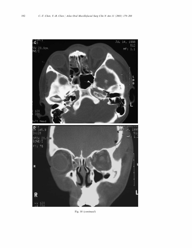
Fig. 10. (A, B) An 18-year-old male patient with a depressed left frontal bone fracture, intracranial hemorrhage, and
left medial orbital wall blow-out fracture after a motorcycle accident. Preoperative appearance showing left ptosis
and enophthalmos (2.5 mm), with diplopia at left gaze. (C, D) Preoperative CT scans reveal a blowout fracture of
the left medial orbital wall. (E, F ) Following careful anatomic repair, there is symmetric projection of the globes at
1-year follow-up. (G, H) The CT scans revealed complete reconstruction of left medial orbital wall with titanium
micromesh.
c

191C.-T. Chen, Y.-R. Chen / Atlas Oral Maxillofacial Surg Clin N Am 11 (2003) 179–208
192 C.-T. Chen, Y.-R. Chen / Atlas Oral Maxillofacial Surg Clin N Am 11 (2003) 179–208
Fig. 10 (continued )

193C.-T. Chen, Y.-R. Chen / Atlas Oral Maxillofacial Surg Clin N Am 11 (2003) 179–208
technique described previously. If there are concomitant orbital medial wall fractures, thenthe bony fragments are removed and the medial wall defect is enlarged to facilitate bettervision of the surgical field. Otherwise, the bony defect is created in the posterior half of theorbital medial wall after coagulation of the posterior ethmoidal vessels to gain access to theoptic foramen. The posterior ethmoidectomy and the sphenoidotomy are performedendoscopically through the same incision. After removal of the anterior surface of thesphenoid sinus, the bulge of the optic canal on the lateral wall of the sphenoid sinus isidentified (Fig. 11A). The thick optic canal ring is thinned by a 2-mm diamond drill andremoved gradually with the endoscopic punch forceps (Fig. 11B). An irrigation system isbuilt into the drill to allow continuous irrigation and prevent transmission of heat from the
Fig. 10 (continued )

194 C.-T. Chen, Y.-R. Chen / Atlas Oral Maxillofacial Surg Clin N Am 11 (2003) 179–208
Fig. 10 (continued )

195C.-T. Chen, Y.-R. Chen / Atlas Oral Maxillofacial Surg Clin N Am 11 (2003) 179–208
bone–drill interface to the nerve. Following this, decompression of the medial wall andpartial roof of the optic canal from the orbital apex are achieved with a small diamond drilland microcurretted in the posterior and superior direction toward the optic chiasm (Fig.11C). This process completes the bony decompression and results in 180� to 270� liberationof the optic nerve on its medial and superior aspects. The procedure is concluded withreconstruction of the orbital medial wall defect to prevent postoperative enophthalmos. Thelength of implants or grafts used to repair the medial wall defect should be less than 3 cm toavoid further compression of the optic nerve.
Results
Results from the author’s center reveal that even patients without light perceptiondemonstrate improvement after surgery, although the probability of improvement is lessthan in patients who maintain some visual acuity. A case example of this procedure is shownin Fig. 12.
Endoscopic diagnosis and repair of the orbital floor fracture
Indications
The method is used not only as a diagnostic tool to observe the fracture status but also as atherapeutic modality to release entrapped periorbital tissue from a trapdoor-type of fractureand to repair the floor defect with grafts. The transantral endoscopic technique is indicated inisolated orbital floor blow-out fractures with or without infraorbital rim fractures or in orbitalfloor fractures in conjunction with medial orbital wall fractures or simple zygomatic fractures.
Fig. 10 (continued )

196 C.-T. Chen, Y.-R. Chen / Atlas Oral Maxillofacial Surg Clin N Am 11 (2003) 179–208
Fig. 11. (A) Endoscopic view of left optic canal (white arrowhead ) and medial optic canal ring (black arrow) with
periorbital tissue retracted laterally (O). (B) Endoscopic view of right optic canal (arrow) being partially thinned by a
diamond burr with protective sheath. (C) Endoscopic view into a sphenoid sinus on the left, exposing the course of the
optic nerve (N), which has been decompressed 180� medially (arrows).

197C.-T. Chen, Y.-R. Chen / Atlas Oral Maxillofacial Surg Clin N Am 11 (2003) 179–208
This technique alone, however, is contraindicated for secondary reconstruction of orbital floorfractures because the severe scarring of prolapsed periorbita prevents dissecting from below.
Technique
Access to the orbital floor is achieved through the maxillary sinus by way of an upperbuccal incision. Subperiosteal dissection proceeds to the level of the infraorbital nervesuperiorly to expose the anterior maxillary wall. A larger antrostomy (2 � 1.5 cm2) is createdusing the oscillating saw. When there are existing fractures over the anterior maxillary wall,they are usually enlarged for placement of the endoscope and endoscopic instruments. A 0�,
Fig. 12. (A) Preoperative photography of a patient with right ptosis, limitation of upper gaze, and vision loss to
hand movement caused by a vehicle accident. She sustained right temporal intracranial hemorrhage and multiple
facial fractures with initial loss of consciousness. Subsequent emergent craniotomy to remove intracranial hematoma
was performed first. (B) The coronal CT scan through the anterior orbital segment shows bilateral Lefort I and
right orbitozygomatic and periorbital fractures involving the lateral wall, floor, and roof. (C ) The coronal CT scan
through the optic apex did not reveal any fracture line or fragmentation. (D) Postoperative appearance 10 months
after repair of facial fractures, and optic nerve decompression with vision improved to 20/200. (E ) Coronal view of
postoperative CT scan revealed the medial wall defect of the optic canal (arrow) after decompression. (F ) Axial view
shows proper reconstruction of the orbital medial wall defect with Medpor implant to prevent postoperative
enophthalmos.

198 C.-T. Chen, Y.-R. Chen / Atlas Oral Maxillofacial Surg Clin N Am 11 (2003) 179–208
Fig. 12 (continued )

199C.-T. Chen, Y.-R. Chen / Atlas Oral Maxillofacial Surg Clin N Am 11 (2003) 179–208
4-mm endoscope is placed through the antrostomy to view and dissect the sinus roof(Fig. 13A). The blood, debris, and comminuted bony fragments are removed first, followed bystripping sinus mucosa to clearly visualize the sinus roof with or without the herniated orbitalcontents (Fig. 13B). When significant (> 1 cm2) orbital floor defects exist, digital pressure ofthe globe posteriorly results in herniation of periorbital tissue into the antrum through theorbital floor fracture. After endoscopic dissection around the fracture site and reduction ofentrapped periorbital tissue, which is reflected upward by a curved malleable retractor, thefracture size, location, and stable margin of the defect on the orbital floor are delineatedclearly.
If the stable bony edges around the floor defect exist, then the defect is reconstructed with apiece of Medpor that is placed intraorbitally over the bony edge through the antrostomy.Otherwise, titanium micromesh is used and cut into a U-shape anteriorly to avoid impingementto the infraorbital nerve, and shaped with a convex contour posteriorly toward the orbital
Fig. 12 (continued )

200 C.-T. Chen, Y.-R. Chen / Atlas Oral Maxillofacial Surg Clin N Am 11 (2003) 179–208
Fig. 12 (continued )

201C.-T. Chen, Y.-R. Chen / Atlas Oral Maxillofacial Surg Clin N Am 11 (2003) 179–208
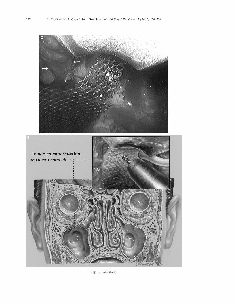
Fig. 13. (A) Access to the maxillary sinus roof by way of an upper buccal incision with an antrostomy. The inset shows
orbital dissector is inserted to reduce the herniated orbital tissue with the aid of endoscope. (B) Endoscopic view of the
left maxillary sinus roof shows the herniated orbital content (arrows) after removal of bony fragments with an
endoscopic grasper. (C) Endoscopic view of the left maxillary sinus roof being reconstructed with micromesh. Note: the
micromesh is cut into a U-shape to avoid compression to the infraorbital nerve (arrows). (D) Illustration of the
transantral repair of the orbital floor using micromesh and microscrew fixation at anterior aspect of sinus roof. The inset
shows the micromesh is fixed with the microscrew under the endoscopic supervision.
202 C.-T. Chen, Y.-R. Chen / Atlas Oral Maxillofacial Surg Clin N Am 11 (2003) 179–208
Fig. 13 (continued )

203C.-T. Chen, Y.-R. Chen / Atlas Oral Maxillofacial Surg Clin N Am 11 (2003) 179–208
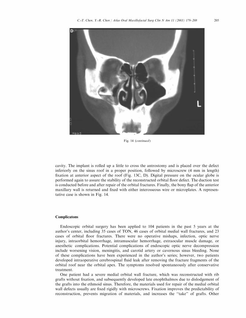
Fig. 14. (A, B) Preoperative photographs of a patient with right enophthalmos (1.5 mm) and right cheek numbness. (C,
D) Preoperative CT images revealed right infraorbital rim segmental depressed fractures and orbital floor blow-out
fractures. (E, F ) Postoperative appearance with symmetry eyeball projection. (G, H ) Postoperative CT scans showed
anatomic reduction of infraorbital rim fractures and well-reconstructed orbital floor defect with Medpor implant.

204 C.-T. Chen, Y.-R. Chen / Atlas Oral Maxillofacial Surg Clin N Am 11 (2003) 179–208
Fig. 14 (continued )
205C.-T. Chen, Y.-R. Chen / Atlas Oral Maxillofacial Surg Clin N Am 11 (2003) 179–208
cavity. The implant is rolled up a little to cross the antrostomy and is placed over the defectinferiorly on the sinus roof in a proper position, followed by microscrew (4 mm in length)fixation at anterior aspect of the roof (Fig. 13C, D). Digital pressure on the ocular globe isperformed again to assure the stability of the reconstructed orbital floor defect. The duction testis conducted before and after repair of the orbital fractures. Finally, the bony flap of the anteriormaxillary wall is returned and fixed with either interosseous wire or microplates. A represen-tative case is shown in Fig. 14.
Complicatons
Endoscopic orbital surgery has been applied to 104 patients in the past 5 years at theauthor’s center, including 35 cases of TON, 46 cases of orbital medial wall fractures, and 23cases of orbital floor fractures. There were no operative mishaps, infection, optic nerveinjury, intraorbital hemorrhage, intramuscular hemorrhage, extraocular muscle damage, oranesthetic complications. Potential complications of endoscopic optic nerve decompressioninclude worsening vision, meningitis, and carotid artery or cavernous sinus bleeding. Noneof these complications have been experienced in the author’s series; however, two patientsdeveloped intraoperative cerebrospinal fluid leak after removing the fracture fragments of theorbital roof near the orbital apex. The symptoms resolved spontaneously after conservativetreatment.
One patient had a severe medial orbital wall fracture, which was reconstructed with ribgrafts without fixation, and subsequently developed late enophthalmos due to dislodgement ofthe grafts into the ethmoid sinus. Therefore, the materials used for repair of the medial orbitalwall defects usually are fixed rigidly with microscrews. Fixation improves the predictability ofreconstruction, prevents migration of materials, and increases the ‘‘take’’ of grafts. Other
Fig. 14 (continued )

206 C.-T. Chen, Y.-R. Chen / Atlas Oral Maxillofacial Surg Clin N Am 11 (2003) 179–208
complications related to the medial transconjunctival approach included transient conjunc-tival granuloma, exophthalmos, and diplopia early in the postoperative period. Postoperativecheek numbness for 2 to 3 months was a common experience in patients treated by endo-scopic transantral approach. Never has there been a case of implant extrusion or sinusitis.Residual enophthalmos is seen occasionally in cases of secondary correction of enophthalmoscaused by the medial orbital wall and floor fractures with or without lateral orbital wallinvolvement.
Fig. 14 (continued )
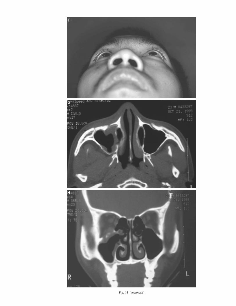
Fig. 14 (continued )

208 C.-T. Chen, Y.-R. Chen / Atlas Oral Maxillofacial Surg Clin N Am 11 (2003) 179–208
Summary
Various applications of endoscopy to orbital surgery are described in this article. Theendoscopic approach offers improved surgical exposure, enhanced illumination, simultaneousvisualization of operative field by multiple members of surgical team, and superior cosmesiscompared with conventional surgical interventions. The procedure can be performed withminimal morbidity. The endoscopic orbital surgery, however, is technique dependent andshould be performed only by surgeons who are familiar with orbital anatomy and basicendoscopic technique. It would be beneficial to surgeons to have previous experience in thetraditional technique before adopting endoscopic orbital surgery to their armamentarium.
Further readings
Chen CT, Chen YR, Tung TC, et al. Endoscopically assisted reconstruction of orbital medial wall fractures. Plast
Reconstr Surg 1999;103:714–20.
Chen CT, Lai JP, Chen YR, et al. Application of endoscope in zygomatic fracture repair. Br J Plast Surg 2000;53:100–5.
Chen CT, Chen YR. Endoscopically assisted repair of orbital floor fractures. Plast Reconstr Surg 2001;108:2011–8.
Forrest CR. Application of endoscope-assisted minimal-access techniques in orbitozygomatic complex, orbital floor, and
frontal sinus fractures. J Cranio-Maxillofac Trauma 1999;5:7–12.
Goldberg RA, Steinsapir KD. Extracranial optic canal decompression: indications and technique. Ophthalmic Plast
Reconstr Surg 1996;12:163–70.
Grant MP, Iliff NT, Manson PN. Strategies for the treatment of enophthalmos. Clin Plast Surg 1997;24:539–50.
Ikeda K, Suzuki H, Oshima T, et al. Endoscopic endonasal repair of orbital floor fracture. Arch Otolaryngol Head Neck
Surg 1999;125:59–63.
Kobayashi S, Sakai Y, Yamada A, et al. Approaching the zygoma with an endoscope. J Craniofac Surg 1995;6:519–24.
Luxenberger W, Stammberger H, Jebeles JA, et al. Endoscopic optic nerve decompression: the Graz experience.
Laryngoscope 1998;108:873–82.
O’Regan MB, Macleod SPR. Miniantrostomy for the reduction of fractures of the orbital floor. Br J Oral Maxillofac
Surg 2000;38:191–2.
Park DH, Lee JW, Song CH, et al. Endoscopic application in aesthetic and reconstructive facial bone surgery. Plast
Reconstr Surg 1998;102:1199–209.
Rontal E, Rontal M, Guilford FT. Surgical anatomy of the orbit. Ann Otol Rhinol Laryngol 1979;88:382–6.
Sandler NA, Carrau RL, Ochs MW, et al. The use of maxillary sinus endoscopy in the diagnosis of orbital floor
fractures. J Oral Maxillofac Surg 1999;57:399–403.
Saunders CJ, Whetzel TP, Stokes RB, Wong GB, Stevenson TR. Transantral endoscopic orbital floor exploration: a
cadaver and clinical study. Plast Reconstr Surg 1997;100:575–81.
Vasconez LO, Core GB, Bamboa-Bobadilla M, et al. Endoscopic techniques in coronal brow lifting. Plast Reconstr Surg
1994;94:788–93.
Woog JJ, Hartstein ME, Gliklich R. Paranasal sinus endoscopy and orbital fracture repair. Arch Ophthalmol
1998;116:688–91.
References
[1] Kobayashi S, Sakai Y, Yamada A, et al. Approaching the zygoma with an endoscope. J Craniofac Surg 1995;6:
519–24.