energy conservation using variable frequency drive in · pdf file ·...
TRANSCRIPT

Energy Conservation Using Variable Frequency Drive in Pumping Application | ISSN: 2321-9939
IJEDRCP1402025 INTERNATIONAL JOURNAL OF ENGINEERING DEVELOPMENT AND RESEARCH | IJEDR(www.ijedr.org)
(Two Day National Conference (RTEECE-2014) -17th ,18th January 2014) 121
Energy Conservation Using Variable Frequency
Drive in Pumping Application 1Mr.Ankur P. Desai,
2Mr.Rakesh.J.Motiyani,
3Dr.Ajitsinh R.Chudasama
1Assitstant Professor,
2Associtate Professor,
3Academic Director
1,2S.N.Patel Institute of Technology & Research Centre,Umrakh,Gujarat,India
3Neotech Technical Campus, Vadodara, Gujarat, India [email protected],
Abstract- Pumping systems account for nearly 20% of the
world’s electrical energy demand and range from 25-50%
of the energy usage in certain industrial plant
operations[1].Pumping systems consume a significant
portion of the electricity, Variable frequency drives
(VFD’s) are often recommended as a way to save pumping
energy. Actual energy savings will vary greatly depending
on how the discharge pressure of the constant speed pump
is controlled and how it is operated after the VFD is
installed. In the present work, the flow of pump has been
controlled by two different methods, Matlab simulations
and experimental work has been carried out and
comparative statement is given in this paper.
Index Terms - Centrifugal pump, flow control, throttling,
variable frequency drive(VFD),Energy saving,Pulse Width
Modulation(PWM).
I. INTRODUCTION
Now to save electricity for our future generation we should be
aware of concept of energy conservation. With energy saving
of 0.01% there is so much benefit to us [1]. So we have to be
aware that where and when electricity should be conserve [2].
The cost of generation of 1 MW power is Many Crores of
Rupees and takes longer years to generate. The cost of 1 MW
power conservation is only less than Rs. 1 Crore. If
Conservation done in morning of the day, the same evening
the industry can reap the rewards of its conservation efforts.
First step is to reduce the defects inside your system and
automatically the Conservation happens to you [3].
Due to the renewed interest in energy saving, it has become
more popular to utilize Electrical Variable Frequency Drives
(VFD) to power pumps which results in significant energy
savings versus mechanical means for adjusting the flow of the
pumping system. Due to the characteristics of pumps it is easy
to misapply motors in VFD pump applications [5].
II. VARIABLE FREQUENCY DRIVE
Variable frequency drives (VFD’s) are often recommended as
a way to save pumping energy. Actual energy savings will
vary greatly depending on how the discharge pressure of the
constant speed pump is controlled and how it is operated after
the VFD is installed [12].
The speed of the motor can be changed by various methods
such as hydraulic or eddy current coupling, variable pulley,
gear box system etc., but most efficient one method is change
the supply frequency and voltage to the motor. The variable
frequency drive (VFD) varies the frequency and hence varies
the speed of the motor as per the requirements by the load
[13].
Speed control of AC/DC motors can be achieved by the
variable speed drive (VSD) unit as shown in fig.2.1. DC drives
are used for special applications such as few low-speed, low-
to-medium power applications because of problems with
mechanical commutation and expensive at large size. Usually
AC drives especially squirrel cage induction motor is widely
used due to its rugged construction, easy installation and
maintenance, higher efficiency and low cost [14].
Figure 2.1 Basic block diagram of VFD.
The variable frequency drive (VFD) converts the supply
frequency and voltage to the required frequency and voltage to
drive a motor. Hence, VFD converts the supply frequency and
voltage to the frequency and voltage required to drive a motor
at a desired speed other than its rated speed [15].
The synchronous speed of an induction motor is given by the
equation as:
Ns=
But actual running speed is always lesser by 2 to 6% of its
speed.
The gap between synchronous speed and running speed is
called the slip.
% S =
x 100………………………………………… (1)
Running speed, N = Ns (1-S)
N =
(1-S)……………………………………………. (2)
So, N ∝ f or N ∝
Thus the running speed of induction is directly proportional to
the supply frequency. If the frequency changes the actual
running speed of motor also changes. VFD controls the
frequency from supply and adjusted to the present requirement
[15].
The basic functions of variable speed drive are to control the
frequency of the supply to the motor and power transfer
efficiently from supply mains to the motor drive shown in
fig.2.1 [15].
Energy Conservation Using Variable Frequency Drive in Pumping Application | ISSN: 2321-9939
IJEDRCP1402025 INTERNATIONAL JOURNAL OF ENGINEERING DEVELOPMENT AND RESEARCH | IJEDR(www.ijedr.org)
(Two Day National Conference (RTEECE-2014) -17th ,18th January 2014) 122
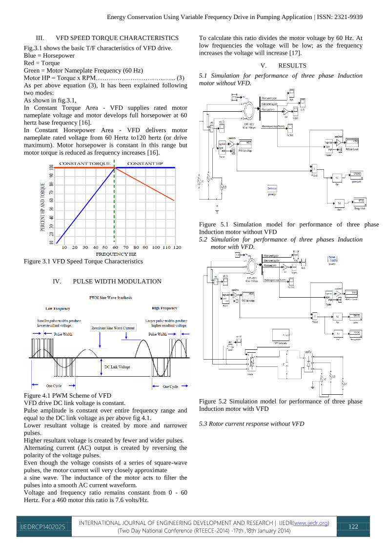
III. VFD SPEED TORQUE CHARACTERISTICS
Fig.3.1 shows the basic T/F characteristics of VFD drive.
Blue = Horsepower
Red = Torque
Green = Motor Nameplate Frequency (60 Hz)
Motor HP = Torque x RPM…………………………..…... (3)
As per above equation (3), It has been explained following
two modes:
As shown in fig.3.1,
In Constant Torque Area - VFD supplies rated motor
nameplate voltage and motor develops full horsepower at 60
hertz base frequency [16].
In Constant Horsepower Area - VFD delivers motor
nameplate rated voltage from 60 Hertz to120 hertz (or drive
maximum). Motor horsepower is constant in this range but
motor torque is reduced as frequency increases [16].
Figure 3.1 VFD Speed Torque Characteristics
IV. PULSE WIDTH MODULATION
Figure 4.1 PWM Scheme of VFD
VFD drive DC link voltage is constant.
Pulse amplitude is constant over entire frequency range and
equal to the DC link voltage as per above fig 4.1.
Lower resultant voltage is created by more and narrower
pulses.
Higher resultant voltage is created by fewer and wider pulses.
Alternating current (AC) output is created by reversing the
polarity of the voltage pulses.
Even though the voltage consists of a series of square-wave
pulses, the motor current will very closely approximate
a sine wave. The inductance of the motor acts to filter the
pulses into a smooth AC current waveform.
Voltage and frequency ratio remains constant from 0 - 60
Hertz. For a 460 motor this ratio is 7.6 volts/Hz.
To calculate this ratio divides the motor voltage by 60 Hz. At
low frequencies the voltage will be low; as the frequency
increases the voltage will increase [17].
V. RESULTS
5.1 Simulation for performance of three phase Induction
motor without VFD.
Figure 5.1 Simulation model for performance of three phase
Induction motor without VFD
5.2 Simulation for performance of three phases Induction
motor with VFD.
Figure 5.2 Simulation model for performance of three phase
Induction motor with VFD
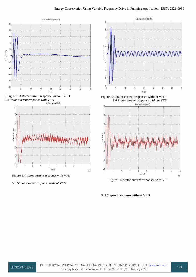
5.3 Rotor current response without VFD
Energy Conservation Using Variable Frequency Drive in Pumping Application | ISSN: 2321-9939
IJEDRCP1402025 INTERNATIONAL JOURNAL OF ENGINEERING DEVELOPMENT AND RESEARCH | IJEDR(www.ijedr.org)
(Two Day National Conference (RTEECE-2014) -17th ,18th January 2014) 123
F Figure 5.3 Rotor current response without VFD
5.4 Rotor current response with VFD
Figure 5.4 Rotor current response with VFD
5.5 Stator current response without VFD
Figure 5.5 Stator current responses without VFD
5.6 Stator current response without VFD
Figure 5.6 Stator current responses with VFD
3 5.7 Speed response without VFD

Energy Conservation Using Variable Frequency Drive in Pumping Application | ISSN: 2321-9939
IJEDRCP1402025 INTERNATIONAL JOURNAL OF ENGINEERING DEVELOPMENT AND RESEARCH | IJEDR(www.ijedr.org)
(Two Day National Conference (RTEECE-2014) -17th ,18th January 2014) 124
Figure 5.7 Speed Waveform without VFD
5.8 Speed response without VFD
Figure 5.8 Speed Waveform without VFD
Table 5.1 Comparison between with & without VFD in
pumping system
Torq
ue
(Nm)
Without VFD With VFD save
Is
Am
p
P
Watts
E
kWh
Is
Am
p
P
Watts
E
kWh
8 4.04
3
2337.
04
140.
22
2.61
4
1698.
52
101.
91
38.3
1
10 4.23
3
2535.
05
152.
10
2.78
5
1809.
63
108.
38
43.7
2
12 4.62
5
2814.
76
168.
89
3.02 1962.
85
117.
77
51.1
2
14 5.24
8
3087.
35
185.
24
3.30
6
2148.
85
128.
93
56.3
1
16 5.62
5
3263.
22
195.
79
3.63
1
2359.
64
141.
38
54.4
1
Table 5.1 Comparison between with & without VFD in
pumping system
5.9 Comparison between with & without VFD in pumping
system
Figure 5.9 Energy Saving Band With & without VFD
VI. TEST SETUP
The schematic diagram of test rig is shown in figure 6.1. It
consists of a water tank, a centrifugal pump, magnetic flow
meter, pressure gauges, and ball valve. The specification of
parts is listed below
Pump Description (Crompton Greaves minimaster
III)
KW/hp :- 0.75/1.00
Head :- 6/45 m
Discharge :- 4000/900 lps
Pump No :- KFPM06914
Flow meter
Magnetic flow meter (ELMAG-200M)
HMI Panel (CVM-NRG96)
HMI panel is used for manual control of VFD drive.
PLC
Siemens S7 200 PLC
PLC is used to control the whole pumping system,
measure input parameters and compare it and give
feed back to the SCADA system.
Pressure Gauges

Energy Conservation Using Variable Frequency Drive in Pumping Application | ISSN: 2321-9939
IJEDRCP1402025 INTERNATIONAL JOURNAL OF ENGINEERING DEVELOPMENT AND RESEARCH | IJEDR(www.ijedr.org)
(Two Day National Conference (RTEECE-2014) -17th ,18th January 2014) 125
Figure 6.1 Schematic diagram of test rig
Figure 6.2 Photo of actual setup
VII. EXPERIMENTAL WORK :
The flow of centrifugal pump has been first controled by
throttling. During test, different electrical and mechanical
paremeter has been recorded which are shown in table 7.1.
Table 7.1 Observation Table (Throttling)
Flow Head Active
Power
Reactiv
e
Power
Apparen
t
Power
Power
Facto
r
Pump
Efficienc
y
m3/h
r
m KW η
3.81 4.23 0.134 0.232 0.26791
0.50 40.95
3.50 6.9523 0.155 0.2436 0.28878
0.53 53.47
3.20 10.153
6
0.172
0.2456 0.29989
0.57 64.54
2.90 14.254
7
0.1816
7 0.246 0.30580
0.59 77.23
2.50 20.322
5
0.2056
7 0.2423 0.31784
0.64 84.14
2.12 25.247
9
0.232
0.2406 0.33428
0.69 78.57
1.51 34.096
3
0.256
0.2433 0.35319
0.72 68.49
Table 7.1 Recorded Electrical and Mechanical DATAs
Experimental without VFD.
Now, flow of centrifugal pump has been controlled by VFD.
During test, different electrical and mechanical parameter has
been recorded which are shown in table 7.2.
Table 7.2 Observation Table (VFD)
Flow Head Active
Power
Reactive
Power
Apparent
Power
Power
Factor
RPM
m3/hr m KW
3.81 5.7791 0.1413 0.033 0.1451 0.97380 2919
3.50 5.1055 0.1183 0.02733 0.1214 0.97434 2703
3.20 4.8520 0.099 0.02266 0.1015 0.97477 2465
2.90 4.1120 0.082 0.01633 0.0836 0.98073 2235
2.50 3.8996 0.065 0.012 0.0661 0.98338 1933
2.12 3.5542 0.0526 0.01 0.0536 0.98244 1632
1.51 3.0254 0.039 0.006 0.0394 0.98837 1172
Table 7.2 Recorded Electrical and Mechanical DATAs
Experimental with VFD.
VIII. CONCLUSION
As by control the flow of pump with throttling, net head
increases and to overcome this extra head motor draw extra
power as shown in table no7.1 & 7.2. VFD offers a very good
response to pumping system. Reduces the flow with VFD,
motor consume very less power. So significant amount of
power can be saved with the help of Variable Frequency Drive
as table no7.1 & 7.2.
As per Matlab Simulations Fig.5.1 (three phase Induction
motor without VFD) and Fig. 5.2 (three phase Induction motor
with VFD) as per result shown in fig.5.9 that electrical energy
can be save by VFD in pumping application. Using VFD,
there are harmonics introduced in above given simulation
results but it can be removed by proper passive or active
filters.
VFD also serves as Soft Starter, during starting motor draws 6
times more current than rated current. While starting with
VFD, motor draws very less current and also provide a smooth
stopping of motor. So the losses occur in motor can be
eliminated.
VFD also improve the Power Factor, Form the table it can be
clearly seen that while controlling the flow with Throttling,
Power Factor remains very low compared to VFD which
maintain the Power Factor near to unity and because of this
the losses regarding to low Power Factor like Increase the I2R
and I2X losses, Increase thermal stresses, increase size of
conductor, circuit breaker etc. reduces.
References
Books
[1] V.K.Gaudani, “Energy efficiency in electrical Systems”
First Edition, IECC Press, 2009.
[2] “Energy efficiency in electrical Utilites “ Bureau of
Energy Efficiency, 2007
[3] G.K.Dubey “Fundamentals of Electrical Drives” Narosa
publishing House, 1994

Energy Conservation Using Variable Frequency Drive in Pumping Application | ISSN: 2321-9939
IJEDRCP1402025 INTERNATIONAL JOURNAL OF ENGINEERING DEVELOPMENT AND RESEARCH | IJEDR(www.ijedr.org)
(Two Day National Conference (RTEECE-2014) -17th ,18th January 2014) 126
[4] Camatini, E, Kester, T, “Heat Pumps and their
Contribution to Energy Conservation” Nato Science
Series E: (closed), Vol. 15 First Edition 1976
[5] G.K. Dubey “Power semiconductor controlled drives”,
Prentice Hall, New Jersey, 1989
[6] B.K. Bose “Modern Power Electronics and AC Drives”,
Prentice Hall , New Delhi 2002
[7] Muhammad H. Rashid “Power Electronics - circuits,
devices and applications”, Prentice Hall of India, 2nd ed.
2000
[8] Mohan, Undeland and Robbins “Power Electronics –
Converters, Applications and Design” , John Willey &
sons, Inc. 3rd ed., 2003
[9] P.C.Sen “Modern Power Electronics ”, S. Chand and Co.
Ltd., New Delhi, 2000
[10] John Webb and Ronald Reis “Programmable Logic
Controllers--principles And Applications” PHI, New
Delhi 5th ed. 2010
Journal/conference paper Ref.: [11] Slobodan A. Mircevski, Zvonimir.A. Kostic, Z. Lj.
Andonov “ Energy Saving With Pump's Ac Adjustable
Speed Drives ” IEEE Electrotechnical Conference,
MELECON 98., 9th Mediterranean (Volume:2 ) 1998.
[12] Walter V. Jones “Motor Selection For Centrifugal Pump
Applications Made Easy “Annual IEEE Pulp and Paper
Industry Technical Conference (PPIC), Conference
Record of 2011.
[13] Mr.Priyank Dave, Mr.Kashyap Mokariya, Mr.Vijay
Patel “ Energy Conservation In Centrifugal Pump With
Variable Frequency Drive Including SCADA, PLC and
HMI . “International Journal of Innovative Research in
Science (IJIRSET), Engineering and Technology Vol. 2,
Issue 5, May 2013.
[14] Herbert W.Weiss, “Adjustable Speed AC Drive Systems
for Pump and Compressor Applications” IEEE
Transactions on Industry applications, vol. Ia-10, no. 1,
january 1974
[15] Dennis A.Jarc, Dennis P.Connors, “Variable Frequency
Drives and Power Factor” IEEE Transactions On Industry
Applications, Vol. Ia-21, No. 4, May/June 1985
[16] Frank A. Dewinter, Brian J.Kedrosky “The Application of
a 3500-hp Variable Frequency Drive for Pipeline Pump
Control” IEEE Transactions On Industry Applications,
Vol. 25, No. 6, Novemberidecember 1989
[17] Peter W.Hammond,"A Universal Controller for Parallel
Pumps with Variable Frequency Drives" IEEE
Transactions On Industry Applications, Vol. Ia-20, No. 1,
January 1984
[18] Lu Xiuhe "Section variable frequency speed regulation
control applied in pump energy saving" IEEE,Computer,
Mechatronics, Control and Electronic Engineering
(CMCE), International Conference on (Volume:3 ) 2010
[19] Ciontu M., Popescu D., Motocu M., "Analysis of energy
efficiency by replacing the throttle valve with variable
speed drive condensate pump from E.C. Turceni"
Electrical and Electronics Engineering (IEEE), 3rd
International Symposium 2010.
Biographies
Prof. (Dr.) A. R. Chudasama was born on May 9, 1956. He
received the M.E degree in
Electrical Power Engineering
from M. S. University, Baroda,
India in 1986. He received the
Doctoral degree from M. S.
University, Baroda, India in
2003. Currently he is working
with Neotech Technical
Campus as Academic Director.
He published & presented more
than 55 research papers in
various leading journals,
seminars and national &
international conferences.
R. J. Motiyani has received the
M.E degree in Electrical Power
Engineering from M. S.
University, Baroda, and Gujarat
in 2005. Currently he is
working with S.N.Patel Institute
of Technology & Research
Centre as Associate Professor in
Electrical Engineering
Department.
A.P. Desai has received the B.E
degree in Electrical Engineering
from VNSGU, Surat; Gujarat in
2008.He has received
M.E.degree in M.E. (electrical
engineering) from Shantilal
shah Engineering college,
Bhavnagar in 2013. Currently
he is working with S.N.Patel
Institute of Technology &
Research Centre as Assistant
Professor in Electrical
Engineering Department.