energy efficiency - abb ltd · in case any errors are ... to growing demand of energy efficiency...
TRANSCRIPT

energy efficiency
ABB, BU Marine and Cranes
Energy efficiency guide
The other alternative fuel
2 | Energy efficiency guide Energy efficiency guide | 3
Foreword 5
1. Energy efficiency in marine vessels 7
2. Design point and energy efficiency 11
3. How can you improve your energy efficiency? 15
4. Energy efficiency solutions 27
4.1. Passenger vessels 32
4.2. Dry cargo vessels 36
4.3. Tankers 40
4.4. Oil & Gas 44
4.5. Work boats 48
5. Solution overviews 53
6. Detailed solution descriptions 77
7. How to proceed 189
Table of contents
Table of contents | Solutions/products | Passenger vessels | Dry Cargo vessels | Tankers | Oil & Gas | Work boatsTable of contents | Solutions/products | Passenger vessels | Dry Cargo vessels | Tankers | Oil & Gas | Work boats
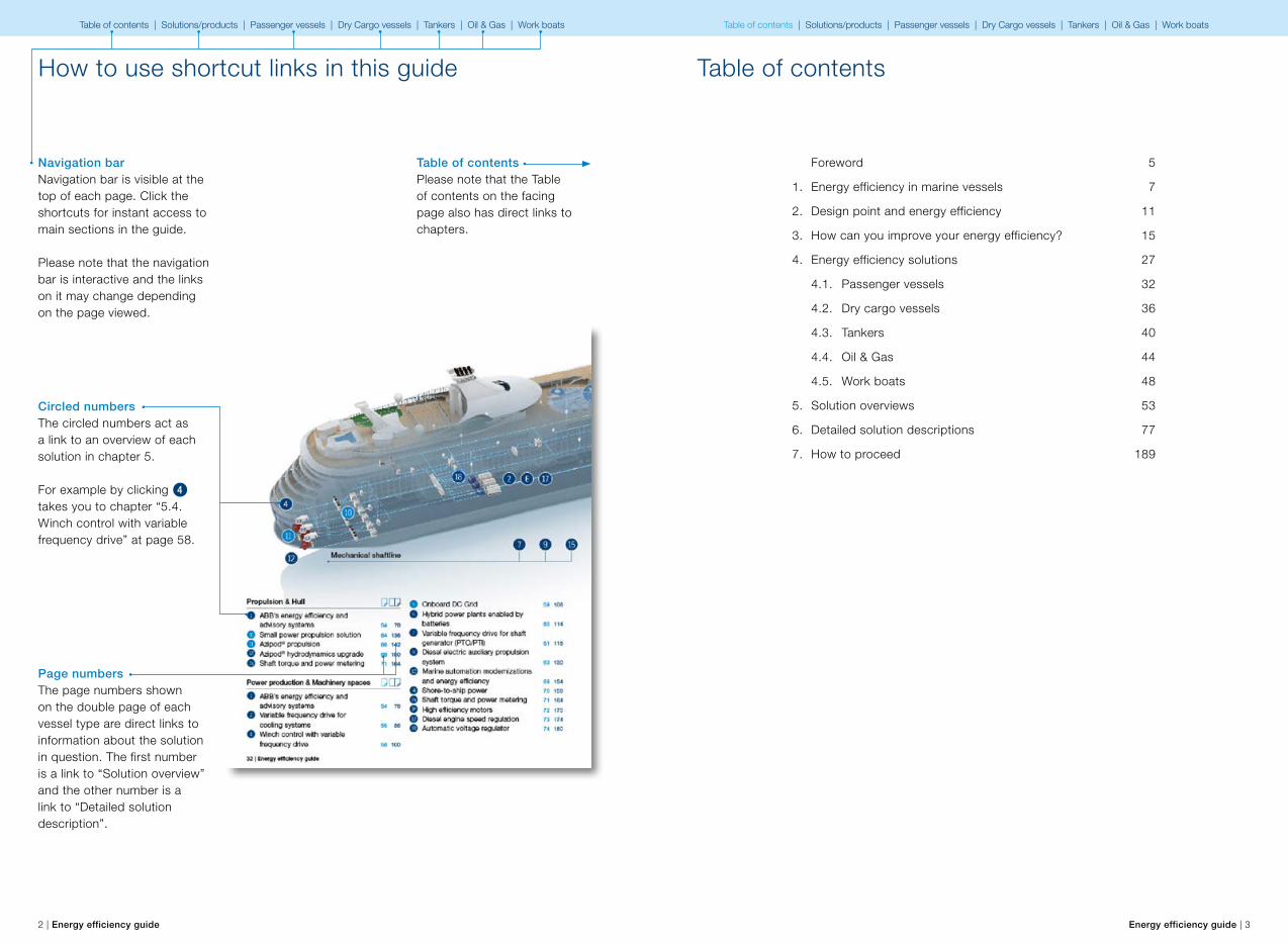
Circled numbersThe circled numbers act as a link to an overview of each solution in chapter 5.
For example by clicking 4 takes you to chapter “5.4. Winch control with variable frequency drive” at page 58.
Page numbersThe page numbers shown on the double page of each vessel type are direct links to information about the solution in question. The first number is a link to “Solution overview” and the other number is a link to “Detailed solution description”.
Table of contentsPlease note that the Table of contents on the facing page also has direct links to chapters.
Navigation barNavigation bar is visible at the top of each page. Click the shortcuts for instant access tomain sections in the guide.
Please note that the navigation bar is interactive and the links on it may change depending on the page viewed.
How to use shortcut links in this guide

4 | Energy efficiency guide Energy efficiency guide | 5
Foreword
Dear reader,Energy efficiency is recognized as a global mandate by governments, maritime organizations and businesses, and has become a key driver for ABB.
Rising operating costs and stricter environmental regulations are driving ship owners/operators, designers and shipyards to find more effective ways of designing and operating ships in an energy efficient manner.
The purpose of this publication is to guide its readers through the latest ideas for improving energy efficiency, in both technical and operational terms. We therefore hope that this guide will find its way onto the desks of as many ship owners/operators, designers and shipyards as possible. You can only maintain your competitive edge by being prepared for the future.
It is difficult to foresee how the world will change, but in ship design one thing is certain – competition between ship owners will intensify and the energy consumed by ships will constitute a larger part of total operating costs. Environmental regulations for ships will become even tighter. A ship built today must remain competitive, in terms of its operating costs and environmental standards, even decades from now. Vessels with electric propulsion provide flexibility in the face of change, enabling ship owners and designers to adapt to emerging challenges.
We hope you enjoy reading this first issue of our energy efficiency publication for the shipping industry. Although this issue will mainly focus on what can be done to reduce fuel consumption on existing ships, all of the measures discussed can also be applied to new ship designs.
Jan-Erik RäsänenEnergy Efficiency Business Manager
Preface
This energy efficiency guide provides data and information for preliminary project evaluation of energy efficiency upgrades or services related to energy efficiency upgrades. Furthermore, our project, service and sales departments are available to advise on more specific questions concerning our products and solutions regarding the various solutions available.
Our energy efficiency and propulsion system offering is constantly reviewed and refined according to the technology development and the needs of our customers. Therefore, we reserve the right to make changes to any data and information herein without notice.
All information provided in this publication is meant to be informative only. All project-specific issues shall be agreed separately and therefore any information given in this publication shall not be used as part of agreement or contract.
Helsinki, April 2013
ABB Oy, Marine and CranesMerenkulkijankatu 1 / P.O. Box 18500981 Helsinki, FinlandTel. +358 10 22 11www.abb.com/marine
Azipod is registered trademark of ABB Oy.© 2005 ABB Oy. All rights reserved
Disclaimer The data, examples and diagrams in this manual are included solely for the concept or product description and are not to be deemed as a statement of guaranteed properties. All persons responsible for applying the equipment addressed in this manual must satisfy themselves that each intended application is suitable and acceptable, including that any applicable safety or other operational requirements are complied with. In particular, any risks in applications where a system failure and/or product failure would create a risk for harm to property or persons (including but not limited to personal injuries or death) shall be the sole responsibility of the person or entity applying the equipment, and those so responsible are hereby requested to ensure that all measures are taken to exclude or mitigate such risks. This document has been carefully checked by ABB but deviations cannot be completely ruled out. In case any errors are detected, the reader is kindly requested to notify the manufacturer. Other than under explicit contractual commitments, in no event shall ABB be responsible or liable for any loss or damage resulting from the use of this manual or the application of the equipment.
© Copyright 2013 ABB. All rights reserved.
Table of contents | Solutions/products | Passenger vessels | Dry Cargo vessels | Tankers | Oil & Gas | Work boats Table of contents | Solutions/products | Passenger vessels | Dry Cargo vessels | Tankers | Oil & Gas | Work boats
6 | Energy efficiency guide Energy efficiency guide | 7
Energy efficiency in marine vessels
1Table of contents | Solutions/products | Passenger vessels | Dry Cargo vessels | Tankers | Oil & Gas | Work boats Table of contents | Solutions/products | Passenger vessels | Dry Cargo vessels | Tankers | Oil & Gas | Work boats
8 | Energy efficiency guide Energy efficiency guide | 9
Energy efficiency in marine vessels
Only a few years ago, fuel efficiency was a minor or even neglected topic in many marine industrial conferences and journals. Today, together with safety and availability, it is at the top of the marine community’s agenda. What has brought such a dramatic change in awareness, in such a short time?
The answer is complex and the causes various. But above all, this development is clearly the result of the dramatic variations in, and high levels of, fuel costs and income rates. This has led to hemorrhaging revenues for ship operators who are unprepared for rapidly changing fuel costs and lack the ability to adjust vessel operations and operational expenses. Another factor concerns increased public awareness of pollution and environmental emissions, which is prompting political decisions on global or local rules and regulations. While these could be considered a burden for ship operators, they may also create huge opportunities for operators with the necessary foresight and long-term strategic perspectives.
This guide will introduce some of the areas in which ABB works, in order to offer solutions that will help ship owners and operators reduce their fuel bills today and in the future. Owners keep their chartered fleet competitive by responding to growing demand of energy efficiency from the industry. These solutions will also support yards in offering vessel designs that meet the future needs. Further and more detailed presentations of core technologies and services can be found in the following chapters.
The fuel dilemma and its opportunities Global shipping consumes around 300 million metric tons of fuel annually, comprising heavy fuel oil (HFO) used in transportation and larger ships, and marine diesel oil (MDO) used in offshore and smaller near-shore vessels. Because HFO is a residual oil product, it is the
lowest priced fuel and is therefore unlikely to be replaced as a main fuel source for shipping in the near future. However, the use of lower-sulfur and cleaner fuels, such as MDO and liquefied natural gas (LNG), will come to dominate parts of the HFO market, as environmental regulations and local restrictions on emissions are tightened.
During the last decade, the energy market has been turbulent, with rising and changing fuel prices. Few voices are predicting that this will change in the next decade. Among ship owners and designers, there is a clear trend towards designing vessels with flexibility in terms of their fuel sources and the operational loading of their propulsion systems.
The challenges involved in achieving macro targets associated with stabilizing CO2 emissions, in order to reduce accelerated global warming, are also bound to affect the shipping industry, even if the related global rules and regulations are not yet in place. Such goals cannot be reached through today’s technologies alone and will require new ways of designing and operating vessels and fleets, as well as further development of technologies and energy sources. While this is a challenge, it also represents a clear money driver for long-term strategic players. With the current cost of HFO at above $600 per metric ton, the shipping industry faces a total annual fuel bill of at least $200 billion. For providers of energy-efficient solutions that reduce fuel consumption for environmental reasons, enormous business opportunities are in prospect, but only based on reduced fuel bills.
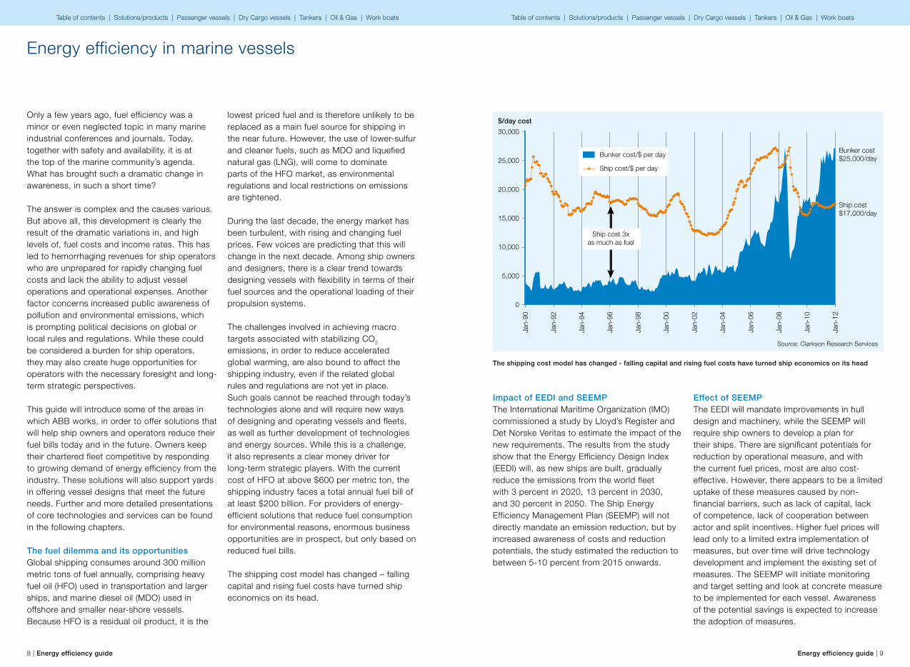
The shipping cost model has changed – falling capital and rising fuel costs have turned ship economics on its head.
Impact of EEDI and SEEMPThe International Maritime Organization (IMO) commissioned a study by Lloyd’s Register and Det Norske Veritas to estimate the impact of the new requirements. The results from the study show that the Energy Efficiency Design Index (EEDI) will, as new ships are built, gradually reduce the emissions from the world fleet with 3 percent in 2020, 13 percent in 2030, and 30 percent in 2050. The Ship Energy Efficiency Management Plan (SEEMP) will not directly mandate an emission reduction, but by increased awareness of costs and reduction potentials, the study estimated the reduction to between 5-10 percent from 2015 onwards.
Effect of SEEMPThe EEDI will mandate improvements in hull design and machinery, while the SEEMP will require ship owners to develop a plan for their ships. There are significant potentials for reduction by operational measure, and with the current fuel prices, most are also cost-effective. However, there appears to be a limited uptake of these measures caused by non-financial barriers, such as lack of capital, lack of competence, lack of cooperation between actor and split incentives. Higher fuel prices will lead only to a limited extra implementation of measures, but over time will drive technology development and implement the existing set of measures. The SEEMP will initiate monitoring and target setting and look at concrete measure to be implemented for each vessel. Awareness of the potential savings is expected to increase the adoption of measures.
The shipping cost model has changed - falling capital and rising fuel costs have turned ship economics on its head
30,000
25,000
20,000
15,000
10,000
5,000
0
Bunker cost$25,000/day
Ship cost 3x as much as fuel
Ship cost/$ per day
Bunker cost/$ per day
$/day cost
Ship cost$17,000/day
Jan-
90
Jan-
92
Jan-
94
Jan-
96
Jan-
98
Jan-
00
Jan-
02
Jan-
04
Jan-
06
Jan-
08
Jan-
10
Jan-
12
Source: Clarkson Research Services
Table of contents | Solutions/products | Passenger vessels | Dry Cargo vessels | Tankers | Oil & Gas | Work boats Table of contents | Solutions/products | Passenger vessels | Dry Cargo vessels | Tankers | Oil & Gas | Work boats
10 | Energy efficiency guide Energy efficiency guide | 11
Design point and energy efficiency
2Table of contents | Solutions/products | Passenger vessels | Dry Cargo vessels | Tankers | Oil & Gas | Work boats Table of contents | Solutions/products | Passenger vessels | Dry Cargo vessels | Tankers | Oil & Gas | Work boats

12 | Energy efficiency guide Energy efficiency guide | 13
Design point and energy efficiency
A key concept in ship design is the design point, a combination of the variables around which a design is developed and optimized. These can be speed, draft, consumption, deadweight, weather and sea conditions, trim (normally even keel) and many other variables, depending on the ship type and operational profile.
In principle, a vessel operating at the design point is as efficient as it can be – everything else being equal. In other words, a vessel designed around a certain design point would have the best optimization for the given variables, i.e. the least fuel consumption, and a certain draft, trim, cargo intake, propeller and hull cleanness and sea/weather conditions.
But what happens if the vessel operates outside its design point? And how often does a vessel do so? What is the range of variation for the different variables?
One could argue that these issues depend on the type of vessel: that in principle no deviation from a design point can exist and the idea is therefore meaningless. In the case of some vessels, this is probably true. But if we look deeper into the operational profile of different types of vessels, we begin to see a different pattern.
A good example of a vessel that barely deviates from its design point is a small/medium inland double ended ferry. The speed is always the same; the deadweight barely changes (even though the cargo deadweight may change considerably) and the weather is fairly stable (assuming a sheltered operating area). On the other hand, a Panamax container carrier that operates globally faces huge variations in weather and seas, needs to operate at a wide range of speeds and is subject to fairly large cargo variations during a round voyage.
Still, there are vessels where the deviation from the design point is less obvious. Take a bulk carrier, for example. These vessels are designed to operate based on two cargo conditions: full and ballast. They are also designed to operate at constant power (i.e. a lower speed with full draft and a higher speed with ballast draft). In addition, the designer assumes that the vessel must be able to maintain its design speed with full draft and under certain weather conditions, and therefore designs for a certain Sea Margin. Normally equaling a percentage of the power required to propel the ship at a certain speed and draft, the Sea Margin is usually set at 10-20%. This means that if the resistance offered by sea states is different to that assumed for the design point, the vessel is likely to move at a different speed or have a different power consumption (either more or less).
Since a seagoing vessel is likely to face a wide range of sea states over its lifecycle – for which the added resistance is likely to be different to the SM used to define the design point – we can conclude that it is highly likely to operate outside its design point for a significant part of its lifetime. Consequently, the vessel will not operate as efficiently as its designers assumed.
The economic implications of the above will depend on how far and how often a vessel operates off the design point.
What happens if the vessel operates outside its design point?
How often and how far does a vessel operate outside its design point?
What is the range of variation for the different variables?
At any rate, the main implication of these considerations is that energy efficiency must be viewed from a much broader perspective. It is not enough to design a vessel that is efficient at a particular design point, if any variation from this would lead to a considerable drop in efficiency. Much can be done at the “drawing board” stage – e.g. optimization for multiple design points. However, in order to achieve a different level of energy efficiency, a sound design must be combined with power management and data management technology that allow the crew to operate the vessel more efficiently across a wider range of conditions.
The design point is the combination of variables around which the design is optimized, e.g. speed, draft, consumption, deadweight, weather and sea conditions, trim, etc.
In principle, a vessel operating at the design point is as efficient as it can be – everything else being equal.
One draft, one speed…or do you need flexibility in design point?
Speed (DWT, Sea, Weather, Fouling, Trim)
Single point optimization
Range optimization
Design range
Design point
Fue
l co
nsum
ptio
n
Table of contents | Solutions/products | Passenger vessels | Dry Cargo vessels | Tankers | Oil & Gas | Work boats Table of contents | Solutions/products | Passenger vessels | Dry Cargo vessels | Tankers | Oil & Gas | Work boats
14 | Energy efficiency guide Energy efficiency guide | 15
How can you improve your energy efficiency?
3Table of contents | Solutions/products | Passenger vessels | Dry Cargo vessels | Tankers | Oil & Gas | Work boats Table of contents | Solutions/products | Passenger vessels | Dry Cargo vessels | Tankers | Oil & Gas | Work boats
16 | Energy efficiency guide Energy efficiency guide | 17
3.1. How can you improve your energy efficiency?
International shipping is facing tough times with escalating fuel prices, stricter environmental regulations and very low day rates caused by overcapacity in most segments. It is not long time ago, when ship cost per day exceeded 5 times the bunker cost per day. Today, dramatic variations and high levels in fuel costs, and major fluctuations in income rates, are causing revenues to hemorrhage for unprepared ship operators that lack the ability to adjust vessel operations and the associated expenses. While HFO costs are now above $600 per metric ton, the shipping industry’s total fuel bill has become an extremely heavy burden for the ship owners.
For providers of energy efficiency solutions, such as ABB, this represents a huge opportunity which could also dramatically ease the situation of ship owners. Another, related factor is increased public awareness of pollution and emissions into the environment, in response to which rules and regulations are being set at both local and global level. While these could be considered a burden on ship operators, for operators with foresight and a long-term
strategic perspective, they may also present vast opportunities.
How to find to the most cost effective solutionsFor ship owners and designers, a broad palette of solutions is available for meeting such challenges. The key question concerns which of these are most cost-effective and which will continue to be suitable in the long-term. However, two tendencies seem to be clear:• For ship owners and designers there is a clear
trend towards increasing efforts to design vessels for flexibility in terms of their fuel source and the operational loading of their propulsion systems.
• There is also increasing interest in reaping the benefits of electric propulsion in new vessel segments, particularly with respect to hybrid propulsion concepts.
This chapter will guide you on how to identify those areas that are essential to maximizing your fleet’s energy efficiency and savings potential.
3.2. Where does the energy and money go?
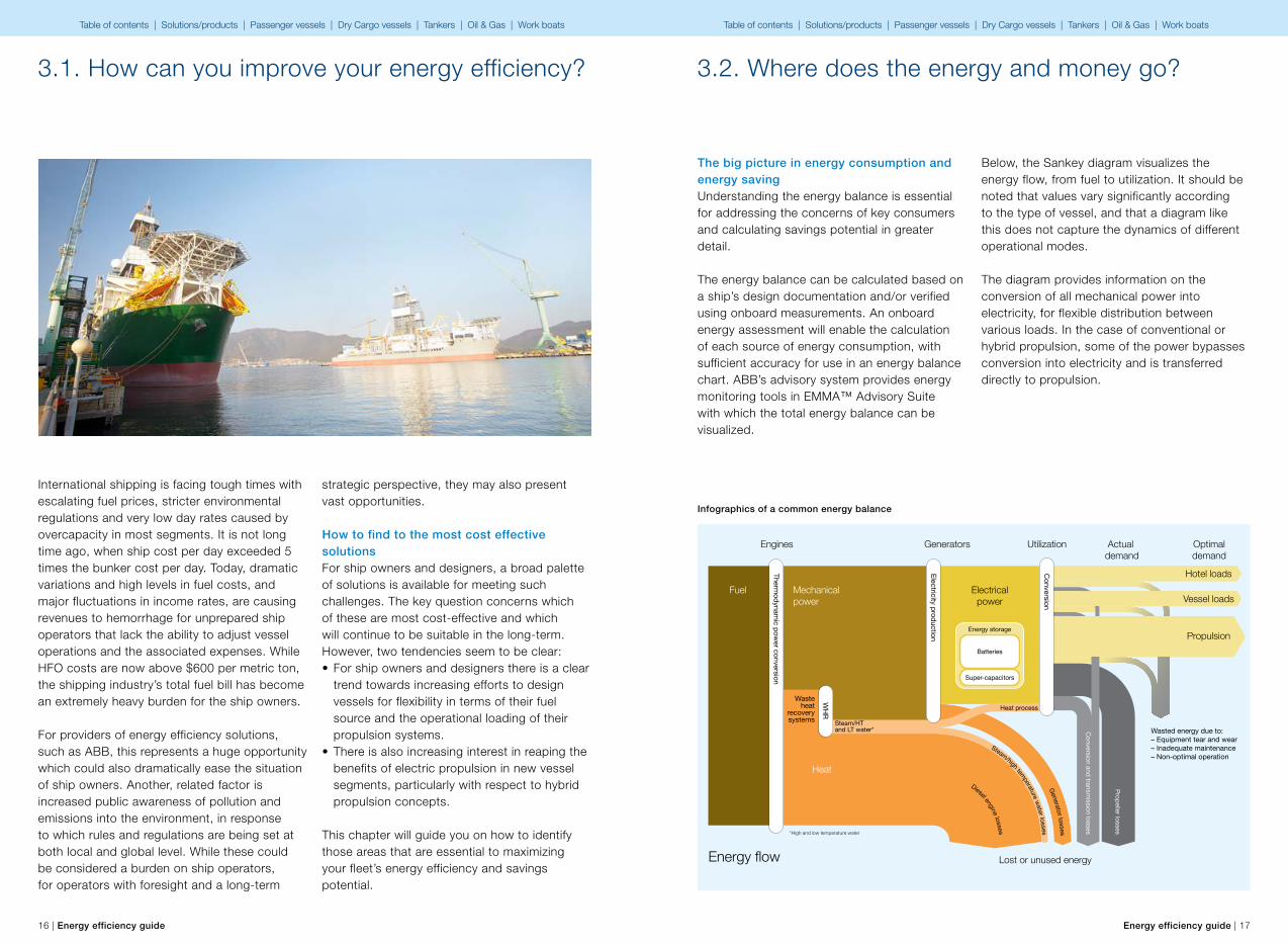
The big picture in energy consumption and energy savingUnderstanding the energy balance is essential for addressing the concerns of key consumers and calculating savings potential in greater detail.
The energy balance can be calculated based on a ship’s design documentation and/or verified using onboard measurements. An onboard energy assessment will enable the calculation of each source of energy consumption, with sufficient accuracy for use in an energy balance chart. ABB’s advisory system provides energy monitoring tools in EMMA™ Advisory Suite with which the total energy balance can be visualized.
Infographics of a common energy balance
Below, the Sankey diagram visualizes the energy flow, from fuel to utilization. It should be noted that values vary significantly according to the type of vessel, and that a diagram like this does not capture the dynamics of different operational modes.
The diagram provides information on the conversion of all mechanical power into electricity, for flexible distribution between various loads. In the case of conventional or hybrid propulsion, some of the power bypasses conversion into electricity and is transferred directly to propulsion.
Fuel
Engines
Energy flow
Generators
Mechanical power
Electricalpower
Heat
Lost or unused energy
Energy storage
Wasteheat
recoverysystems
Thermodynam
ic power conversion
Utilization
Batteries
Optimaldemand
Actual demand
Wasted energy due to:– Equipment tear and wear – Inadequate maintenance – Non-optimal operation
Propeller losses
Super-capacitors
Diesel engine losses
Steam/high temperature water lossesGenerator losses
Electricity production
Conversion
Hotel loads
Vessel loads
Propulsion
Conversion and transm
ission losses
WH
R Heat process
Steam/HT and LT water*
*High and low temperature water
Table of contents | Solutions/products | Passenger vessels | Dry Cargo vessels | Tankers | Oil & Gas | Work boats Table of contents | Solutions/products | Passenger vessels | Dry Cargo vessels | Tankers | Oil & Gas | Work boats
18 | Energy efficiency guide Energy efficiency guide | 19
In the case of cruise ships, a primary utilization factor would provide comfort to guests (the hotel load). For platform support vessels, dynamic positioning would be more useful while, for tankers, the speed from A to B is the key issue. The type of work done onboard would vary in each case – the width of the arrows indicates how the amount of energy consumed would change from one minute to the next.
In static terms, we can fundamentally view the diagram as representing the energy accounted for during one year in operation, or as the energy flow for an entire fleet.
By reading the diagram from left to right, you can readily see how a large portion of the fuel turns into waste heat due to the inefficiency of the combustion engine. However, reading the diagram from right to left could provide an even more valuable insight into how the cost driver on the left, fuel consumption, could be tamed more effectively. Improvements in the processes on the right would affect the left side by a factor of two or three.
The most effective strategy for achieving improved energy efficiency and reducing fuel costs would be extremely simple: closing the gap between optimal and actual demand.
3.3. There are many ways to improve energy efficiency. How to focus on the right things?
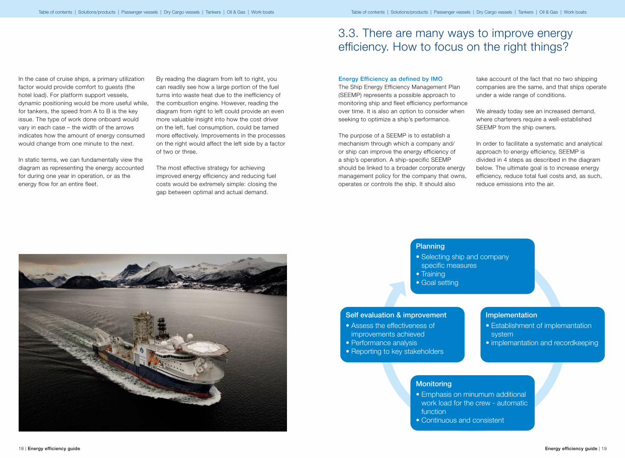
Energy Efficiency as defined by IMOThe Ship Energy Efficiency Management Plan (SEEMP) represents a possible approach to monitoring ship and fleet efficiency performance over time. It is also an option to consider when seeking to optimize a ship’s performance.
The purpose of a SEEMP is to establish a mechanism through which a company and/or ship can improve the energy efficiency of a ship’s operation. A ship-specific SEEMP should be linked to a broader corporate energy management policy for the company that owns, operates or controls the ship. It should also
take account of the fact that no two shipping companies are the same, and that ships operate under a wide range of conditions.
We already today see an increased demand, where charterers require a well-established SEEMP from the ship owners.
In order to facilitate a systematic and analytical approach to energy efficiency, SEEMP is divided in 4 steps as described in the diagram below. The ultimate goal is to increase energy efficiency, reduce total fuel costs and, as such, reduce emissions into the air.
Planning
• Selecting ship and company specific measures• Training• Goal setting
Self evaluation & improvement
• Assess the effectiveness of improvements achieved• Performance analysis• Reporting to key stakeholders
Implementation
• Establishment of implemantation system• implemantation and recordkeeping
Monitoring
• Emphasis on minumum additional work load for the crew - automatic function• Continuous and consistent
Table of contents | Solutions/products | Passenger vessels | Dry Cargo vessels | Tankers | Oil & Gas | Work boats Table of contents | Solutions/products | Passenger vessels | Dry Cargo vessels | Tankers | Oil & Gas | Work boats
20 | Energy efficiency guide Energy efficiency guide | 21
Step 0• Understand where
you are• Analyze current
operations• Set targets and
make a plan• Begin follow-up
Step 1• Concentrate on
simple improvements• Daily operation and
maintenance• Focus on zero or
low-cost items
Step 2• Improvement of
systems• Minor modifications
during normal operation
• Focus on items with a payback period of less than two years
Step 3• Improvement of
systems and ship hull
• Modifications requiring dry docking
Fuel consumption
Fuel consumption
Fuel consumption
Fuel consumption
Systematic approach to energy savings by ABBABB’s straightforward and systematic approach is illustrated below. It begins by identifying where you are on the scale of efficiency and ends with the implementation of the most energy-efficient approach. Ultimately, while operation of the ship includes technical measures, services such as energy efficiency audits and training play a key role in achieving a more efficient operation.
A SEEMP is used to establish a mechanism enabling a company and/or ship to improve the energy efficiency of a ship’s operation.
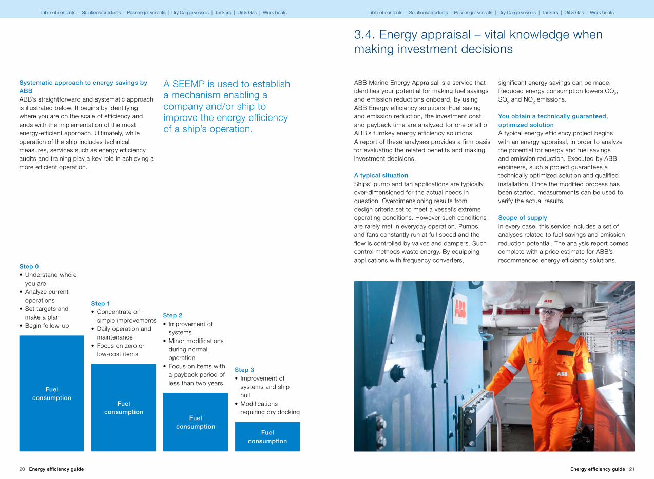
ABB Marine Energy Appraisal is a service that identifies your potential for making fuel savings and emission reductions onboard, by using ABB Energy efficiency solutions. Fuel saving and emission reduction, the investment cost and payback time are analyzed for one or all of ABB’s turnkey energy efficiency solutions. A report of these analyses provides a firm basis for evaluating the related benefits and making investment decisions.
A typical situationShips’ pump and fan applications are typically over-dimensioned for the actual needs in question. Overdimensioning results from design criteria set to meet a vessel’s extreme operating conditions. However such conditions are rarely met in everyday operation. Pumps and fans constantly run at full speed and the flow is controlled by valves and dampers. Such control methods waste energy. By equipping applications with frequency converters,
significant energy savings can be made. Reduced energy consumption lowers CO2, SOX and NOX emissions.
You obtain a technically guaranteed, optimized solutionA typical energy efficiency project begins with an energy appraisal, in order to analyze the potential for energy and fuel savings and emission reduction. Executed by ABB engineers, such a project guarantees a technically optimized solution and qualified installation. Once the modified process has been started, measurements can be used to verify the actual results.
Scope of supplyIn every case, this service includes a set of analyses related to fuel savings and emission reduction potential. The analysis report comes complete with a price estimate for ABB’s recommended energy efficiency solutions.
3.4. Energy appraisal – vital knowledge when making investment decisions
Table of contents | Solutions/products | Passenger vessels | Dry Cargo vessels | Tankers | Oil & Gas | Work boats Table of contents | Solutions/products | Passenger vessels | Dry Cargo vessels | Tankers | Oil & Gas | Work boats

22 | Energy efficiency guide Energy efficiency guide | 23
Why?The objective of an energy audit is to bring a vessel’s overall energy efficiency to a clearly higher level, by identifying various operational and technical improvement options. The outcome of the audit is a detailed roadmap for achieving possible energy efficiency improvements, with estimated investment costs and saving potential.
What?Such an audit includes an assessment of the main machinery and equipment, as well as the evaluation of ship operations and maintenance practices in all of the relevant areas. Reporting of the audit’s results includes:• Actual proposals for improving fuel efficiency
in all areas of the vessel.• The economic feasibility of all identified
improvements is evaluated by estimating the saving in operational costs.
• An outline of SEEMP, required by IMO for all ships, can be included.
ReportingThe written audit report includes an audit plan and targets, the main findings from the onboard assessment with estimated savings and costs, and a wrap-up presentation with a roadmap for achieving energy efficiency improvements.
3.5. Energy efficiency audit – the first concrete step towards saving energy, the environment and money
Energy efficiency audit
An outline of SEEMP, required by IMO for all ships, can be included in energy efficiency audit
Environmental efficiency auditEnergy efficiency audit stepsFind the potential• Behaviors and practices• Monitoring and targeting• Technology and control
Introduce the options• Alignment workshops and prioritization
process• Quick-win project implementation• Project specification• Opportunity confirmation
Gain the benefits• Best-in-the-field equipment• Advisory solutions• Services and assistance
Why?The objective of an environmental efficiency audit is the most accurate identification and quantification possible of emissions into the environment during typical vessel operation. In addition, the possibilities, both technical and operational, for reducing emissions are evaluated.
What?You will obtain a comprehensive picture of your multiple technical and operational possibilities for reducing the fuel consumption of your vessel(s). Your improvement potential is quantified, based on estimated investments and annual savings.
Table of contents | Solutions/products | Passenger vessels | Dry Cargo vessels | Tankers | Oil & Gas | Work boats Table of contents | Solutions/products | Passenger vessels | Dry Cargo vessels | Tankers | Oil & Gas | Work boats

24 | Energy efficiency guide Energy efficiency guide | 25
Energy efficiency trainingThe scope of energy efficiency training includes improving the fuel economy of vessel(s) by raising crew awareness when operating the ship and its machinery. This is done through both theoretical examples and practical principles. The related training sessions consist of an interactive combination of lectures, case studies and discussions on energy efficiency. Training material includes basic theoretical guidelines applicable to the selected vessel and operation. Participants should include chief engineers, captains and any other key persons (shore/ship/technical) proposed by the client. Training can be arranged at your office, onboard or at a training center.
3.6. Energy and environmental efficiency trainings
Environmental efficiency trainingThe objective of environmental efficiency training is to lower vessels’ impact on the environment by raising crew awareness of various environmental issues. The emphasis is laid on technical and operational means of reducing emissions, as well as on current and forthcoming legislation. Participants should include chief engineers and captains, and any other key persons (shore/ship/technical) chosen by the client.
By acknowledging the current status, and understanding measures for optimizing processes, action can be taken to reduce energy consumption.
What you getis increased knowledge and awareness among your crew of energy and environmental efficiency and the related issues. Greater knowledge reduces fuel consumption over a longer timeframe, through enhanced competencies among the crew and possible adjustments to daily operations.• Providing the big picture on fuel saving
onboard• Refreshing your theoretical knowledge of the
ship and her systems• Providing practical evaluation tools and
methods• Strengthening the commitment to a common
goal• Includes interactive workshop for initializing
creation of a company SEEMP
Benefits for the ship ownerAwareness of energy- and environmental efficiency enables the owner to determine and monitor the current status of the vessel’s energy production, consumption and emissions. Actions to reduce energy consumption can be performed by understanding the ship’s current status and the measures required to optimize processes. The results will appear in terms of increased competencies amongst the crew, and their understanding of the potential for reducing the vessel’s operating costs.
Table of contents | Solutions/products | Passenger vessels | Dry Cargo vessels | Tankers | Oil & Gas | Work boats Table of contents | Solutions/products | Passenger vessels | Dry Cargo vessels | Tankers | Oil & Gas | Work boats
26 | Energy efficiency guide Energy efficiency guide | 27
Energy efficiency solutions
4Table of contents | Solutions/products | Passenger vessels | Dry Cargo vessels | Tankers | Oil & Gas | Work boats Table of contents | Solutions/products | Passenger vessels | Dry Cargo vessels | Tankers | Oil & Gas | Work boats
8i24
4
o
321ut1py7 9Mechanical shaftline
28 | Energy efficiency guide Energy efficiency guide | 29
Energy efficiency solutions
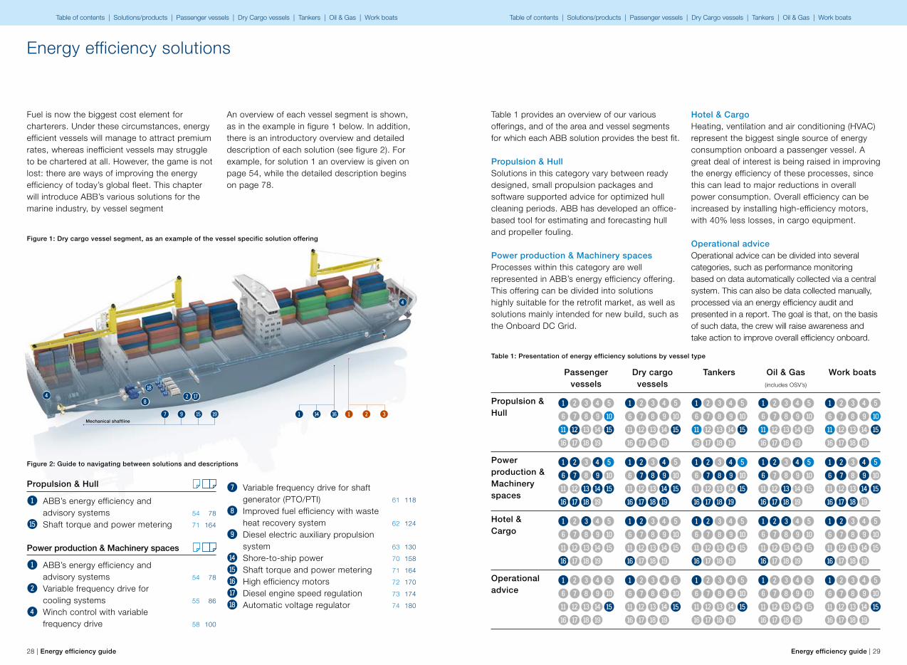
Fuel is now the biggest cost element for charterers. Under these circumstances, energy efficient vessels will manage to attract premium rates, whereas inefficient vessels may struggle to be chartered at all. However, the game is not lost: there are ways of improving the energy efficiency of today’s global fleet. This chapter will introduce ABB’s various solutions for the marine industry, by vessel segment
An overview of each vessel segment is shown, as in the example in figure 1 below. In addition, there is an introductory overview and detailed description of each solution (see figure 2). For example, for solution 1 an overview is given on page 54, while the detailed description begins on page 78.
Figure 1: Dry cargo vessel segment, as an example of the vessel specific solution offering
Figure 2: Guide to navigating between solutions and descriptions
Propulsion & Hull
1 ABB’s energy efficiency and advisory systems 54 78
y Shaft torque and power metering 71 164
Power production & Machinery spaces
1 ABB’s energy efficiency and advisory systems 54 78
2 Variable frequency drive for cooling systems 55 86
4 Winch control with variable frequency drive 58 100
7 Variable frequency drive for shaft generator (PTO/PTI) 61 118
8 Improved fuel efficiency with waste heat recovery system 62 124
9 Diesel electric auxiliary propulsion system 63 130
t Shore-to-ship power 70 158
y Shaft torque and power metering 71 164
u High efficiency motors 72 170
i Diesel engine speed regulation 73 174
o Automatic voltage regulator 74 180
12345
6789q
werty
uiop
12345
6789q
werty
uiop
12345
6789q
werty
uiop
12345
6789q
werty
uiop
12345
6789q
werty
uiop
Propulsion & Hull
Passenger vessels
Dry cargo vessels
Tankers Oil & Gas(includes OSV’s)
Work boats
12345
6789q
werty
uiop
12345
6789q
werty
uiop
12345
6789q
werty
uiop
12345
6789q
werty
uiop
12345
6789q
werty
uiop
Power production & Machinery spaces
12345
6789q
werty
uiop
12345
6789q
werty
uiop
12345
6789q
werty
uiop
12345
6789q
werty
uiop
12345
6789q
werty
uiop
Hotel & Cargo
12345
6789q
werty
uiop
12345
6789q
werty
uiop
12345
6789q
werty
uiop
12345
6789q
werty
uiop
12345
6789q
werty
uiop
Operational advice
Table 1 provides an overview of our various offerings, and of the area and vessel segments for which each ABB solution provides the best fit.
Propulsion & HullSolutions in this category vary between ready designed, small propulsion packages and software supported advice for optimized hull cleaning periods. ABB has developed an office-based tool for estimating and forecasting hull and propeller fouling.
Power production & Machinery spacesProcesses within this category are well represented in ABB’s energy efficiency offering. This offering can be divided into solutions highly suitable for the retrofit market, as well as solutions mainly intended for new build, such as the Onboard DC Grid.
Hotel & CargoHeating, ventilation and air conditioning (HVAC) represent the biggest single source of energy consumption onboard a passenger vessel. A great deal of interest is being raised in improving the energy efficiency of these processes, since this can lead to major reductions in overall power consumption. Overall efficiency can be increased by installing high-efficiency motors, with 40% less losses, in cargo equipment.
Operational adviceOperational advice can be divided into several categories, such as performance monitoring based on data automatically collected via a central system. This can also be data collected manually, processed via an energy efficiency audit and presented in a report. The goal is that, on the basis of such data, the crew will raise awareness and take action to improve overall efficiency onboard.
Table 1: Presentation of energy efficiency solutions by vessel type
Table of contents | Solutions/products | Passenger vessels | Dry Cargo vessels | Tankers | Oil & Gas | Work boats Table of contents | Solutions/products | Passenger vessels | Dry Cargo vessels | Tankers | Oil & Gas | Work boats

30 | Energy efficiency guide Energy efficiency guide | 31
Solutions/products and consulting services to be introduced in this guide
Solutions Products1 ABB’s energy efficiency
and advisory systemsA vast portfolio of performance management tools for minimizing fuel costs, and maximizing the availability and improving the overall safety of vessels.
2 Variable frequency drive for cooling systems
A simple and efficient way to achieve major savings in fuel consumption on various onboard pump and fan applications.
3 Variable frequency drive to control HVAC systems
Controlling pumps and fans in HVAC processes with VFD provides substantial savings in fuel consumption and reduced maintenance costs.
4 Winch control with variable frequency drive
A smooth, stepless speed and torque control solution, with a special winch control program and Direct Torque Control feature for increasing system reliability.
5 Onboard DC Grid Up to 20% fuel saving when taking full advantage of all features, including energy storage and variable speed engines. Improved dynamic response in DP mode.
6 Hybrid power plants enabled by batteries
An additional and/or alternative power source to diesel generator sets, providing reduced fuel consumption and enabling zero emission operation.
7 Variable frequency drive for shaft generator (PTO/PTI)
Use the shaft generator in a wider operating window, enabling the use of a hybrid solution with flexibility in power intake and output modes.
8 Improved fuel efficiency with waste heat recovery system
Through the WHRS, recovered energy, typically 10% of the main propulsion’s shaft power, is converted back for mechanical work.
9 Diesel electric auxiliary propulsion system
A simple approach to improving a vessel’s operational profile involves installing an electrical auxiliary propulsion system for CPP operated vessels running at low speeds: 0–6 kn.
q Small power propulsion solution
Small power range of ready-designed electrical propulsion system packages; typical power range of 100 to 400 kW is highly suitable for smaller vessels.
w Azipod® propulsion A podded electric main propulsion and steering system driving a fixed-pitch propeller at variable speed, known for its high hydrodynamic efficiency.
e Azipod® hydrodynamics upgrade
A retrofit package for further improving Azipod® hydrodynamic efficiency, with the fuel savings effect occurring across the vessel’s entire speed range.
r Marine automation modernizations and energy efficiency
Run your systems closer to peak efficiency, combine the automation retrofit with an advisory system to increase your awareness of power production and consumption.
Consulting services These services are applicable to all vessel types
1 Energy appraisal An easy way to increase awareness of fuel savings and emissions reduction potential. A customized study that enables the improvement of a vessel’s energy efficiency.
2 Energy efficiency audit For clearly improving the overall energy efficiency of a vessel by identifying various operational and technical improvement options.
3 Energy efficiency training To improve the fuel economy of vessel(s) by raising crew awareness when operating the ship and its machinery.
Solutions Productst Shore-to-ship power Shut down all of your engines while berthed and reduce your
emissions to zero. Gain a reduced fuel bill, by using onshore power.
y Shaft torque and power metering
Do you know whether your engines are running optimally? Accurate shaft power and RPM measurement can help determine whether this is so.
u High efficiency motors ABB high efficiency motors meet the highest efficiency requirements in all load points. This enables the use of VFDs in all motor applications. Losses reduced by 40%.
i Diesel engine speed regulation
The DEGO III digital governor system not only reduces fuel consumption and maintenance, creating savings in operating costs, but also cuts exhaust emissions.
o Automatic voltage regulator UNITROL® 1000 products, designed for compliance with worldwide grid codes, for reliable control of a machine, even during heavy failure conditions on the network.
p Two stroke diesel engine performance monitoring
A well-tuned and balanced engine consumes less fuel. ABB Cylmate® System enables fuel-consumption reductions of around 1–2%, with a short payback time.
1 Product/solution applicable for both retrofits and new vessels
2 Product/solution feasible mainly for new vessels
Table of contents | Solutions/products | Passenger vessels | Dry Cargo vessels | Tankers | Oil & Gas | Work boats Table of contents | Solutions/products | Passenger vessels | Dry Cargo vessels | Tankers | Oil & Gas | Work boats

32 | Energy efficiency guide Energy efficiency guide | 33
Propulsion & Hull
1 ABB’s energy efficiency and advisory systems 54 78
q Small power propulsion solution 64 136
w Azipod® propulsion 66 142
e Azipod® hydrodynamics upgrade 68 150
y Shaft torque and power metering 71 164
Power production & Machinery spaces
1 ABB’s energy efficiency and advisory systems 54 78
2 Variable frequency drive for cooling systems 55 86
4 Winch control with variable frequency drive 58 100
5 Onboard DC Grid 59 106
6 Hybrid power plants enabled by batteries 60 114
7 Variable frequency drive for shaft generator (PTO/PTI) 61 118
9 Diesel electric auxiliary propulsion system 63 130
r Marine automation modernizations and energy efficiency 69 154
t Shore-to-ship power 70 158
y Shaft torque and power metering 71 164
u High efficiency motors 72 170
i Diesel engine speed regulation 73 174
o Automatic voltage regulator 74 180
q4
w
e
o 2 6 i
y7 9Mechanical shaftline
Passenger vessels
1 2 3Product/solution applicable for both retrofits and new vessels
Product/solution feasible mainly for new vessels
Consulting service Solution overview Detailed solution description
Hotel & Cargo
1 ABB’s energy efficiency and advisory systems 54 78
3 Variable frequency drive to control HVAC systems 56 92
u High efficiency motors 72 170
Operational advice
1 ABB’s energy efficiency and advisory systems 54 78
y Shaft torque and power metering 71 164
4
o 2 6 i
Consulting services
1 Energy appraisal 21
2 Energy efficiency audit 22
3 Energy efficiency training 24
r51 u3 t 321
Table of contents | Solutions/products | Passenger vessels | Dry Cargo vessels | Tankers | Oil & Gas | Work boats Table of contents | Solutions/products | Passenger vessels | Dry Cargo vessels | Tankers | Oil & Gas | Work boats
5 ye
ars
3 ye
ars
1 ye
ar
50 kUSD 500 kUSD 5000 kUSDAverage investment cost
Aver
age
payb
ack
time
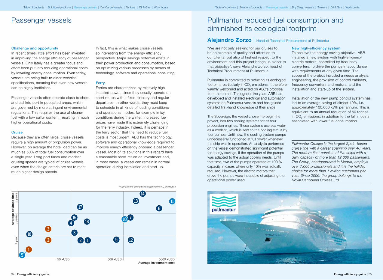
Pullmantur reduced fuel consumption and diminished its ecological footprint
Alejandro Zorzo | Head of Technical Procurement at Pullmantur
New high-efficiency systemTo achieve the energy-saving objective, ABB installed a new system with high-efficiency electric motors, controlled by frequency converters, to drive the pumps in accordance with requirements at any given time. The scope of the project included a needs analysis, engineering, the provision of control cabinets, frequency converters and motors, and the installation and start-up of the system.
Installation of the new pump control system has led to an average saving of almost 40%, i.e. approximately 100,000 kWh per annum. This is equivalent to an annual reduction of 50 tonnes in CO2 emissions, in addition to the fall in costs associated with lower fuel consumption.
Pullmantur Cruises is the largest Spain-based cruise line with a career spanning over 40 years. The modern fleet consists of five ships with a daily capacity of more than 12,000 passengers. The Group, headquartered in Madrid, employs over 7,000 professionals and it is the holiday choice for more than 1 million customers per year. Since 2006, the group belongs to the Royal Caribbean Cruises Ltd.
“We are not only seeking for our cruises to be an example of quality and attention to our clients, but also of highest respect to the environment and this project brings us closer to that objective”, says Alejandro Zorzo, head of Technical Procurement at Pullmantur.
Pullmantur is committed to reducing its ecological footprint, particularly in CO2 emissions. It therefore warmly welcomed and acted on ABB’s proposal from the outset. Throughout the years ABB has developed and installed electrical and automation systems on Pullmantur vessels and has gained detailed first-hand knowledge of their ships.
The Sovereign, the vessel chosen to begin the project, has two cooling systems for its four propulsion engines. These systems use sea water as a coolant, which is sent to the cooling circuit by four pumps. Until now, the cooling system pumps unnecessarily functioned at full power whenever the ship was in operation. An analysis performed on the vessel demonstrated significant potential for energy savings, if the operation of the pumps was adapted to the actual cooling needs. Until that time, two of the pumps operated at 100 % capacity in cases where only 40% was actually required. However, the electric motors that drove the pumps were incapable of adjusting the operational power used.
34 | Energy efficiency guide Energy efficiency guide | 35
Challenge and opportunityIn recent times, little effort has been invested in improving the energy efficiency of passenger vessels. Only lately has a greater focus and effort been put into reducing operational costs by lowering energy consumption. Even today, vessels are being built to older technical specifications, meaning that even new vessels can be highly inefficient.
Passenger vessels often operate close to shore and call into port in populated areas, which are governed by more stringent environmental regulations. This requires the use of cleaner fuel with a low sulfur content, resulting in much higher operational costs.
CruiseBecause they are often large, cruise vessels require a high amount of propulsion power. However, on average the hotel load can be as much as 50% of total fuel consumption over a single year. Long port times and modest cruising speeds are typical of cruise vessels, even when the design criteria are set to meet much higher design speeds.
Passenger vessels
In fact, this is what makes cruise vessels so interesting from the energy efficiency perspective. Major savings potential exists in their power production and consumption, based on optimizing various processes by means of technology, software and operational consulting.
Ferry Ferries are characterized by relatively high installed power, since they usually operate on short routes with a fixed itinerary and regular departures. In other words, they must keep to schedule in all kinds of loading conditions and operational modes, for example in icy conditions during the winter. Increased fuel prices have made this extremely challenging for the ferry industry. Indeed, it is perhaps in the ferry sector that the need to reduce fuel costs is most urgent. ABB has the technology, software and operational knowledge required to improve energy efficiency onboard a passenger vessel. Most of its solutions in this regard have a reasonable short return on investment and, in most cases, a vessel can remain in normal operation during installation and start-up.
w
e
rt
6
7q
9
i
u4y
33
2
1
21o
*) Compared to conventional diesel electric AC distribution
5*
Table of contents | Solutions/products | Passenger vessels | Dry Cargo vessels | Tankers | Oil & Gas | Work boats Table of contents | Solutions/products | Passenger vessels | Dry Cargo vessels | Tankers | Oil & Gas | Work boats
36 | Energy efficiency guide Energy efficiency guide | 37
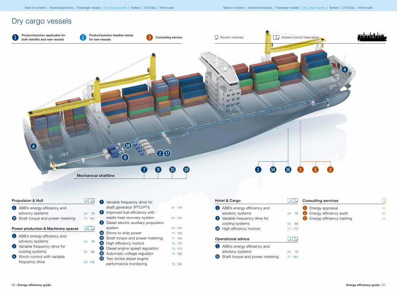
Propulsion & Hull
1 ABB’s energy efficiency and advisory systems 54 78
y Shaft torque and power metering 71 164
Power production & Machinery spaces
1 ABB’s energy efficiency and advisory systems 54 78
2 Variable frequency drive for cooling systems 55 86
4 Winch control with variable frequency drive 58 100
7 Variable frequency drive for shaft generator (PTO/PTI) 61 118
8 Improved fuel efficiency with waste heat recovery system 62 124
9 Diesel electric auxiliary propulsion system 63 130
t Shore-to-ship power 70 158
y Shaft torque and power metering 71 164
u High efficiency motors 72 170
i Diesel engine speed regulation 73 174
o Automatic voltage regulator 74 180
p Two stroke diesel engine performance monitoring 75 184
8i2
4 o
py7 9Mechanical shaftline
Dry cargo vessels
1 2 3Product/solution applicable for both retrofits and new vessels
Product/solution feasible mainly for new vessels
Consulting service Solution overview Detailed solution description
Hotel & Cargo
1 ABB’s energy efficiency and advisory systems 54 78
2 Variable frequency drive for cooling systems 55 86
u High efficiency motors 72 170
Operational advice
1 ABB’s energy efficiency and advisory systems 54 78
y Shaft torque and power metering 71 164
4
321ut1
Consulting services
1 Energy appraisal 21
2 Energy efficiency audit 22
3 Energy efficiency training 24
Table of contents | Solutions/products | Passenger vessels | Dry Cargo vessels | Tankers | Oil & Gas | Work boats Table of contents | Solutions/products | Passenger vessels | Dry Cargo vessels | Tankers | Oil & Gas | Work boats
5 ye
ars
3 ye
ars
1 ye
ar
50 kUSD 500 kUSD 5000 kUSDAverage investment cost
Aver
age
payb
ack
time
38 | Energy efficiency guide Energy efficiency guide | 39
Dry cargo vessels
p
8
t
7
9
i
u4y
3
2
1
21o
Container carriersSince the maiden voyage of the M.V. ”Ideal X” in 1956, with a consignment of 58 containers, the container industry has never stopped growing. This has driven the development of bigger ships and engines. Container carriers are currently used to transport around 90% of non-bulk cargo worldwide. The industry has been gaining efficiency by building bigger and faster vessels. On long-haul routes, vessels such as the “Emma Maersk” are enabling the achievement of unprecedentedly low transport unit costs ($/TEU.nm). However, the rise in fuel costs has brought energy efficiency into focus. Although size is still a key driver of transport efficiency, greater effort is now being directed at reducing the “fuel bill”.
The largest marine engines can be found in today’s large container vessels. Although these, mainly slow speed, two-stroke diesel engines are the most energy-efficient propulsion engines, even they only achieve an energy efficiency of 50%. In addition, modern container vessels have a growing number of reefer slots, with a high requirement for electric power, usually produced by three to four powerful diesel generator sets. Together, these present huge opportunities for efficiency gains.
The strict emission regulations pose a major challenge to short-distance shipping. For feeder
container carriers, which represent the smaller end of this segment, this means adapting to sharp increases in fuel prices and increasingly stringent environmental requirements.
Challenge and opportunityA container carrier is traditionally designed for a certain route and speed. But what if these demands change? The pace of globalization has already shown that cargo flows are changing much faster than vessel lifecycles. Consequently, ship owners are seeking vessel designs that are as flexible as possible, with a variety of power sources that can produce the power required for different scenarios, as well as an advisory system that can inform them of the most energy efficient approach to meeting demand.
High-efficiency turbochargers and Waste Heat Recovery Systems (WHRS) can transform a considerable amount of waste heat into usable energy. Electricity produced by WHRS significantly increases overall efficiency, reducing CO2 emissions by tons.
Our shaft generator provides cost effective, environmentally-neutral electric power to onboard services when required. When excess electric power is available, it is used to boost the propulsion system.
“With these solutions, we are better equipped to help ship operators reduce fuel consumption efficiently and provide added-value technology to all ship owners,” says Heikki Soljama, head of the ABB business unit Marine and Cranes.
“It is vital that EMMA is providing real time relevant data to the crew so they can analyze the areas where the vessel’s performance is lacking. To be able to be proactive you need to know your baseline, your current condition and the best possible conditions at that very moment, not one day or six hours after, “commented the customer.
Different analyses with EMMA has revealed that while savings of 10%-plus can be achieved from implementing such procedures as propeller polishing and hull conditions, clear voyage instructions, autopilot settings, trim and ballast conditions and weather routing. There are masses of things that cost little or nothing but there are prerequisites, much of fuel saving is due to the attitude and training of the crew onboard whether on the bridge or in the engine room.
EMMA will take us and the whole industry a huge step forward
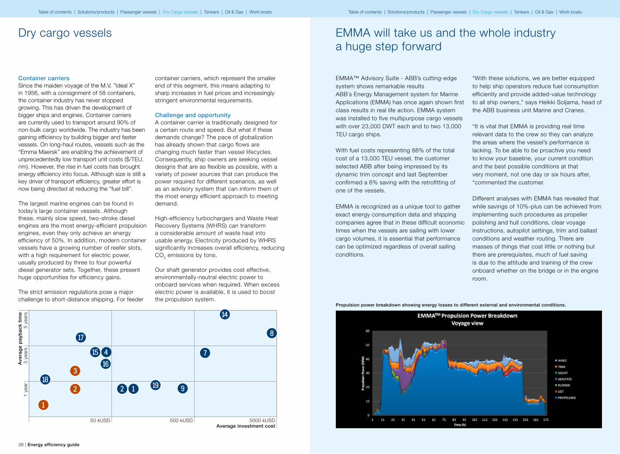
EMMA™ Advisory Suite - ABB’s cutting-edge system shows remarkable resultsABB´s Energy Management system for Marine Applications (EMMA) has once again shown first class results in real life action. EMMA system was installed to five multipurpose cargo vessels with over 23,000 DWT each and to two 13,000 TEU cargo ships.
With fuel costs representing 88% of the total cost of a 13,000 TEU vessel, the customer selected ABB after being impressed by its dynamic trim concept and last September confirmed a 6% saving with the retrofitting of one of the vessels.
EMMA is recognized as a unique tool to gather exact energy consumption data and shipping companies agree that in these difficult economic times when the vessels are sailing with lower cargo volumes, it is essential that performance can be optimized regardless of overall sailing conditions.
Propulsion power breakdown showing energy losses to different external and environmental conditions.
Table of contents | Solutions/products | Passenger vessels | Dry Cargo vessels | Tankers | Oil & Gas | Work boats Table of contents | Solutions/products | Passenger vessels | Dry Cargo vessels | Tankers | Oil & Gas | Work boats
40 | Energy efficiency guide Energy efficiency guide | 41
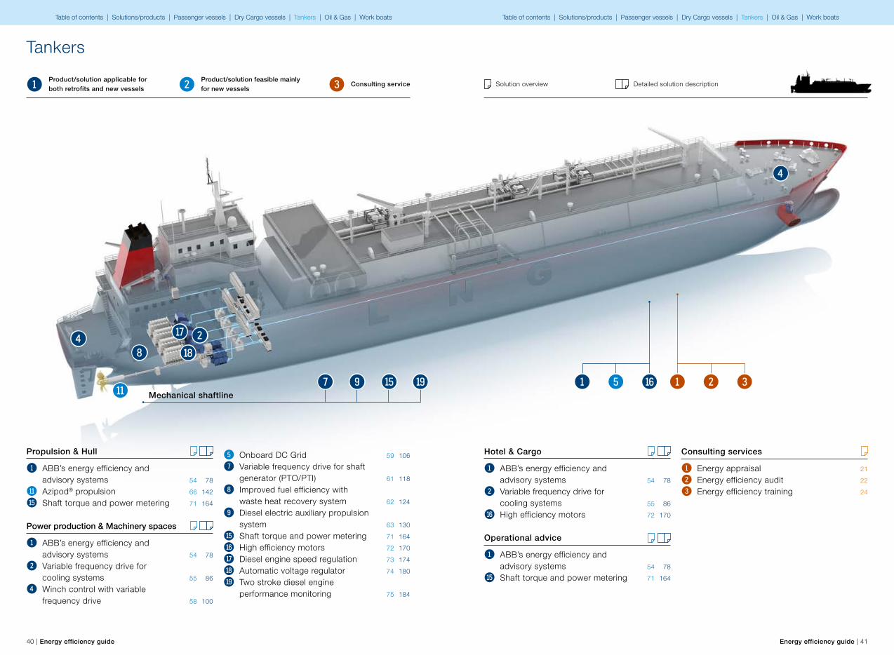
Propulsion & Hull
1 ABB’s energy efficiency and advisory systems 54 78
w Azipod® propulsion 66 142
y Shaft torque and power metering 71 164
Power production & Machinery spaces
1 ABB’s energy efficiency and advisory systems 54 78
2 Variable frequency drive for cooling systems 55 86
4 Winch control with variable frequency drive 58 100
5 Onboard DC Grid 59 106
7 Variable frequency drive for shaft generator (PTO/PTI) 61 118
8 Improved fuel efficiency with waste heat recovery system 62 124
9 Diesel electric auxiliary propulsion system 63 130
y Shaft torque and power metering 71 164
u High efficiency motors 72 170
i Diesel engine speed regulation 73 174
o Automatic voltage regulator 74 180
p Two stroke diesel engine performance monitoring 75 184
w
8
i4 2o
py7 9Mechanical shaftline
Tankers
1 2 3Product/solution applicable for both retrofits and new vessels
Product/solution feasible mainly for new vessels
Consulting service Solution overview Detailed solution description
Hotel & Cargo
1 ABB’s energy efficiency and advisory systems 54 78
2 Variable frequency drive for cooling systems 55 86
u High efficiency motors 72 170
Operational advice
1 ABB’s energy efficiency and advisory systems 54 78
y Shaft torque and power metering 71 164
4
321u51
Consulting services
1 Energy appraisal 21
2 Energy efficiency audit 22
3 Energy efficiency training 24
Table of contents | Solutions/products | Passenger vessels | Dry Cargo vessels | Tankers | Oil & Gas | Work boats Table of contents | Solutions/products | Passenger vessels | Dry Cargo vessels | Tankers | Oil & Gas | Work boats
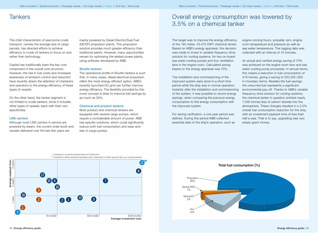
Total fuel consumption [%]
Saving EV 2%
Saving SWC 1%
Aux 12%
Propulsion85%
42 | Energy efficiency guide Energy efficiency guide | 43
5 ye
ars
3 ye
ars
1 ye
ar
50 kUSD 500 kUSD 5000 kUSDAverage investment cost
Aver
age
payb
ack
time
The chief characteristic of sea-borne crude transport, namely the average size of cargo parcels, has directed efforts to achieve efficiency in crude oil tankers to focus on size rather than technology.
Capital has traditionally been the key cost component in the overall cost structure. However, the rise in fuel costs and increased awareness of emission control and reduction have recently drawn the attention of charterers and operators to the energy efficiency of these types of vessels.
On the other hand, the tanker segment is not limited to crude tankers, since it includes other types of vessels, each with their own specificities.
LNG carriersAlthough most LNG carriers in service are powered by steam, the current order-book and vessels delivered over the last few years are
mainly powered by Diesel Electric/Dual Fuel (DE/DF) propulsion plants. This propulsion solution provides much greater efficiency than traditional plants. However, many opportunities remain for optimising the related power plants, using software developed by ABB.
Shuttle tankersThe operational profile of Shuttle tankers is such that, in many cases, diesel electrical propulsion offers the most energy-efficient option. ABB’s recently launched DC-grid can further improve energy efficiency. The flexibility provided by this novel concept is likely to improve fuel savings by as much as 30%.
Chemical and product tankersMost product and chemical tankers are equipped with several cargo pumps, which require a considerable amount of power. ABB has specific solutions, which could significantly reduce both fuel consumption and wear-and-tear in cargo pumps.
8
7
p 9
i
u4y
3
2
1
21o
* Compared to conventional diesel electric AC distribution
** Compared to diesel-mechanical propulsion plant. Dependent on tanker type and size, e.g. ice-going tankers.
w* *
5*
Tankers Overall energy consumption was lowered by 3.5% on a chemical tanker
The target was to improve the energy efficiency of the 182 meter, 43,475 DWT chemical tanker. Based on ABB’s energy appraisal, the decision was made to invest in variable frequency drive solution for cooling systems, for two on board sea water cooling pumps and four ventilation fans in the engine room. Calculated saving based on the energy appraisal was 70%.
The installation and commissioning of the improved system were done in a short time period while the ship was in normal operation. Instantly after the installation and commissioning of the system, it was possible to record energy savings, when comparing the previous energy consumption to the energy consumption with the improved system.
For saving verification, a one year period was defined. During this period ABB collected essential data of the ship’s operation, such as
engine running hours, propeller rpm, engine room temperature and pressure as well as sea water temperature. The logging data was collected with an interval of 10 minutes.
An actual and verified energy saving of 72% was achieved on the engine room fans and sea water cooling pump processes. In annual terms, this means a reduction in fuel consumption of 319 tonnes, giving a saving of 220,000 USD in monetary terms. Besides the fuel savings, the unburned fuel represents a significant environmental pay-off. Thanks to ABB’s variable frequency drive solution for cooling systems, the chemical tanker in question emitted nearly 1,000 tonnes less of carbon dioxide into the atmosphere. These changes resulted in a 3.5% overall fuel consumption reduction for the ship, with an investment payback time of less than half a year. That is to say, upgrading was very wisely spent money.
Table of contents | Solutions/products | Passenger vessels | Dry Cargo vessels | Tankers | Oil & Gas | Work boats Table of contents | Solutions/products | Passenger vessels | Dry Cargo vessels | Tankers | Oil & Gas | Work boats
44 | Energy efficiency guide Energy efficiency guide | 45
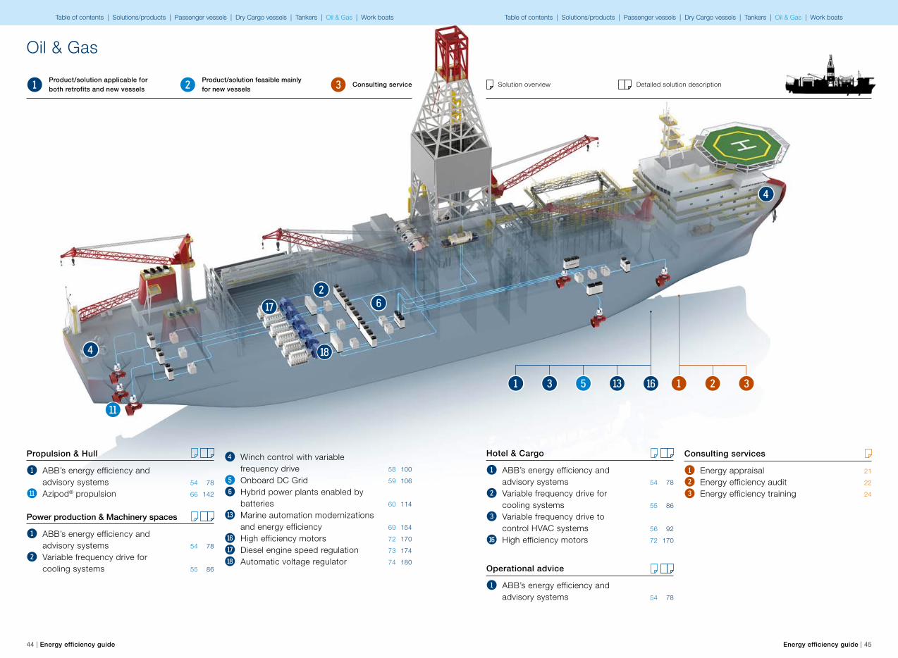
Propulsion & Hull
1 ABB’s energy efficiency and advisory systems 54 78
w Azipod® propulsion 66 142
Power production & Machinery spaces
1 ABB’s energy efficiency and advisory systems 54 78
2 Variable frequency drive for cooling systems 55 86
4 Winch control with variable frequency drive 58 100
5 Onboard DC Grid 59 106
6 Hybrid power plants enabled by batteries 60 114
r Marine automation modernizations and energy efficiency 69 154
u High efficiency motors 72 170
i Diesel engine speed regulation 73 174
o Automatic voltage regulator 74 180
4
i 62
o
w
Oil & Gas
1 2 3Product/solution applicable for both retrofits and new vessels
Product/solution feasible mainly for new vessels
Consulting service Solution overview Detailed solution description
Hotel & Cargo
1 ABB’s energy efficiency and advisory systems 54 78
2 Variable frequency drive for cooling systems 55 86
3 Variable frequency drive to control HVAC systems 56 92
u High efficiency motors 72 170
Operational advice
1 ABB’s energy efficiency and advisory systems 54 78
4
Consulting services
1 Energy appraisal 21
2 Energy efficiency audit 22
3 Energy efficiency training 24
321ur3 51
Table of contents | Solutions/products | Passenger vessels | Dry Cargo vessels | Tankers | Oil & Gas | Work boats Table of contents | Solutions/products | Passenger vessels | Dry Cargo vessels | Tankers | Oil & Gas | Work boats
5 ye
ars
3 ye
ars
1 ye
ar
50 kUSD 500 kUSD 5000 kUSDAverage investment cost
Aver
age
payb
ack
time
46 | Energy efficiency guide Energy efficiency guide | 47
Oil & Gas
We have seen increased demand for the opening up of new areas of oil production. New technologies enable drilling in deep waters, and there is high demand for new drilling vessels with the required extra capabilities.
Vessel typesA floating vessel is required for offshore drilling deeper than 120 m. Semi-submersibles obtain their buoyancy from ballasted, watertight pontoons located below the ocean surface and wave action. Due to high stability, the operating deck can be located high above sea level. Through de-ballasting, a semi-submersible vessel can be transformed from a deep into a shallow draft.
Drill ships are most often used for the exploratory offshore drilling of new oil or gas wells. They can also be used as platforms when performing well maintenance or completion work, such as casing and tubing installation. The greatest advantage lies in their ability to drill in water depths of more than 2,500 m and in the time saved when sailing between oilfields worldwide.
Offshore support vessels (OSV), such as platform supply vessels, anchor handling tug supply vessels, rescue vessels and ice breaking OSV are specially designed to supply offshore oil
r6
4
39
i
u3
2
1
21
o
rigs and platforms. Despite this, for much of the time they operate on stand-by at platforms.
Challenge and opportunityLarge seawater and ballast pumps are extensively used on drilling vessels. These pumps unnecessarily run continuously at 100%, leading to excessive energy and fuel consumption. A variable frequency drive system for controlling pump speed brings significant energy savings.
The power plant/switchboard configuration can be designed so that the number of running diesel engines required is dependent on the vessel’s overall power requirement, rather than the switchboard configuration.
The variable power consumption of OSVs makes them excellent candidates for the Onboard DC Grid system. Due to redundancy considerations, DP vessels often run several diesel generators in parallel. This means that the connected diesel engines spend most of their running hours at relatively low loads, at which fuel efficiency is significantly lower than at optimal load.
For DP equipped vessels, advisory systems with advanced features enable maximized workability and additional productive hours during DP operations.
* Compared to conventional diesel electric AC distribution
** Compared to mechanical thruster with electrical drive. Dependent on vessel size.
w* *
5*
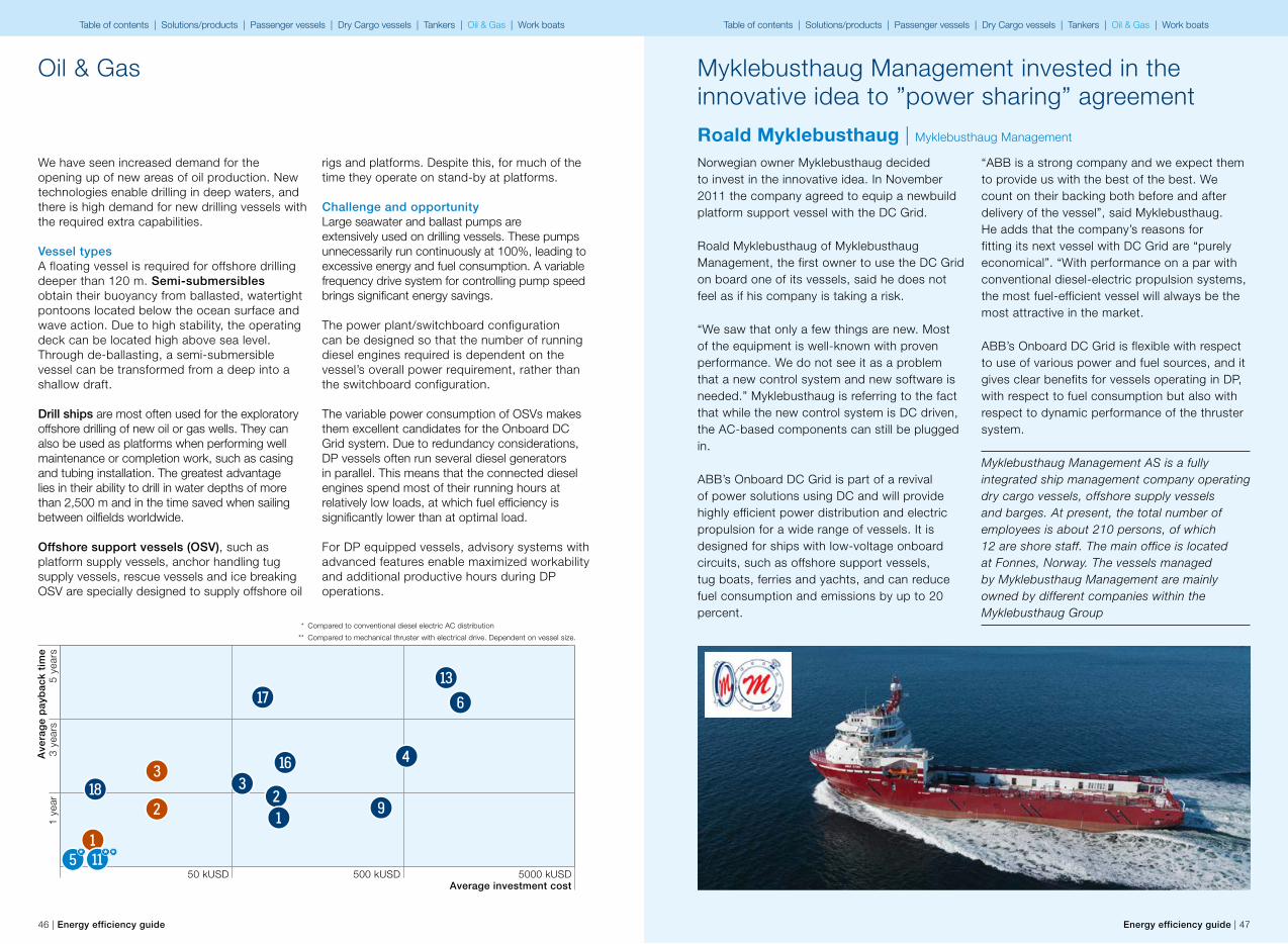
Roald Myklebusthaug | Myklebusthaug Management
Norwegian owner Myklebusthaug decided to invest in the innovative idea. In November 2011 the company agreed to equip a newbuild platform support vessel with the DC Grid.
Roald Myklebusthaug of Myklebusthaug Management, the first owner to use the DC Grid on board one of its vessels, said he does not feel as if his company is taking a risk.
“We saw that only a few things are new. Most of the equipment is well-known with proven performance. We do not see it as a problem that a new control system and new software is needed.” Myklebusthaug is referring to the fact that while the new control system is DC driven, the AC-based components can still be plugged in.
ABB’s Onboard DC Grid is part of a revival of power solutions using DC and will provide highly efficient power distribution and electric propulsion for a wide range of vessels. It is designed for ships with low-voltage onboard circuits, such as offshore support vessels, tug boats, ferries and yachts, and can reduce fuel consumption and emissions by up to 20 percent.
“ABB is a strong company and we expect them to provide us with the best of the best. We count on their backing both before and after delivery of the vessel”, said Myklebusthaug. He adds that the company’s reasons for fitting its next vessel with DC Grid are “purely economical”. “With performance on a par with conventional diesel-electric propulsion systems, the most fuel-efficient vessel will always be the most attractive in the market.
ABB’s Onboard DC Grid is flexible with respect to use of various power and fuel sources, and it gives clear benefits for vessels operating in DP, with respect to fuel consumption but also with respect to dynamic performance of the thruster system.
Myklebusthaug Management AS is a fully integrated ship management company operating dry cargo vessels, offshore supply vessels and barges. At present, the total number of employees is about 210 persons, of which 12 are shore staff. The main office is located at Fonnes, Norway. The vessels managed by Myklebusthaug Management are mainly owned by different companies within the Myklebusthaug Group
Myklebusthaug Management invested in the innovative idea to ”power sharing” agreement
Table of contents | Solutions/products | Passenger vessels | Dry Cargo vessels | Tankers | Oil & Gas | Work boats Table of contents | Solutions/products | Passenger vessels | Dry Cargo vessels | Tankers | Oil & Gas | Work boats
48 | Energy efficiency guide Energy efficiency guide | 49
Propulsion & Hull
1 ABB’s energy efficiency and advisory systems 54 78
q Small power propulsion solution 64 136
w Azipod® propulsion 66 142
y Shaft torque and power metering 71 164
Power production & Machinery spaces
1 ABB’s energy efficiency and advisory systems 54 78
2 Variable frequency drive for cooling systems 55 86
4 Winch control with variable frequency drive 58 100
5 Onboard DC Grid 59 106
6 Hybrid power plants enabled by batteries 60 114
7 Variable frequency drive for shaft generator (PTO/PTI) 61 118
9 Diesel electric auxiliary propulsion system 63 130
t Shore-to-ship power 70 158
y Shaft torque and power metering 71 164
u High efficiency motors 72 170
i Diesel engine speed regulation 73 174
o Automatic voltage regulator 74 180
4
q
w y7 9Mechanical shaftline
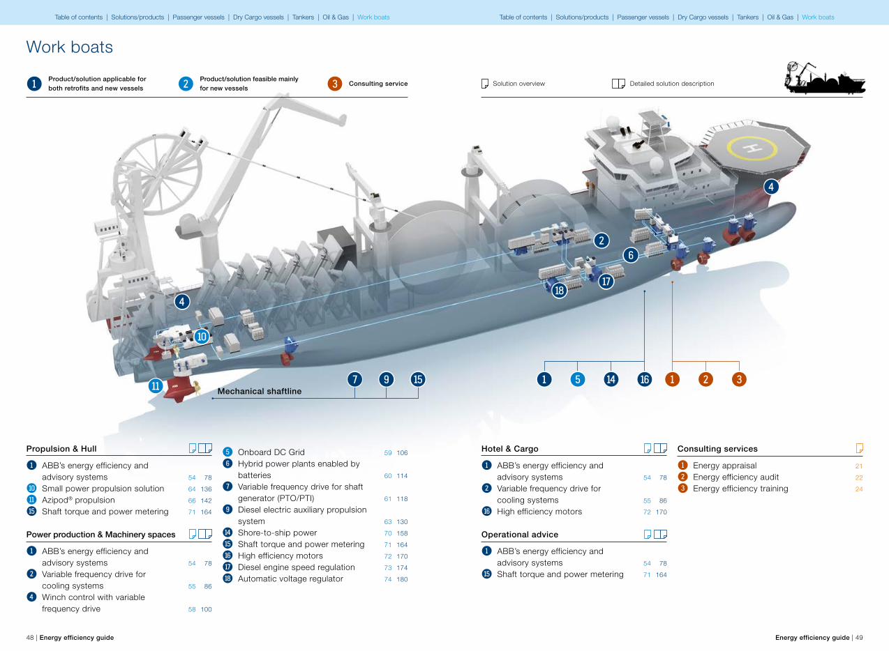
Work boats
1 2 3Product/solution applicable for both retrofits and new vessels
Product/solution feasible mainly for new vessels
Consulting service Solution overview Detailed solution description
Hotel & Cargo
1 ABB’s energy efficiency and advisory systems 54 78
2 Variable frequency drive for cooling systems 55 86
u High efficiency motors 72 170
Operational advice
1 ABB’s energy efficiency and advisory systems 54 78
y Shaft torque and power metering 71 164
6
4
i
2
o
321ut51
Consulting services
1 Energy appraisal 21
2 Energy efficiency audit 22
3 Energy efficiency training 24
Table of contents | Solutions/products | Passenger vessels | Dry Cargo vessels | Tankers | Oil & Gas | Work boats Table of contents | Solutions/products | Passenger vessels | Dry Cargo vessels | Tankers | Oil & Gas | Work boats
5 ye
ars
3 ye
ars
1 ye
ar
50 kUSD 500 kUSD 5000 kUSDAverage investment cost
Aver
age
payb
ack
time
50 | Energy efficiency guide Energy efficiency guide | 51
Work boats
t
64y q
9
i
u3
2
1
21o
Challenge and opportunityVessels working in harbor areas and close to coastlines face environmental pressure from land-based communities. This new pressure has changed the design of certain vessel types, such as harbor tugs. Riding the same wave of environmental awareness, the related design principles are spreading to vessel types that operate further from the coast. In this case, the main driving force is the savings potential gained by efficient operational design for partial loads. This equation means electrical propulsion systems.
Tugs, harbor tugs, pushers, pullers, dredgers and other small but powerful ships are typically made in series. While their design philosophy was originally well considered, the final execution of the design does vary, and may lead to operations where fuel consumption is well above that required.
The move from mechanical to electrical propulsion will continue to gather pace, while the need to create a low-consuming idle mode is increasing. This is leading to updates involving electrical auxiliary propulsion, concept changes in traditional diesel-electrical solutions.
In order to carry out their missions, tugs are equipped with large engines – considering their relatively small size in particular. However, most of the time tugs use less than 25% of the installed power, which means that the main engines are operated either on idle or at a very low load. Consequently, these types of vessels are amongst the least energy efficient types. However, electrical propulsion combined with energy storage is opening up new possibilities for the design of tugs, allowing these vessels to achieve a completely new level of energy efficiency. Combined, these two technologies could improve specific fuel consumption dramatically at most operating ranges, optimize the performance of winches through peak shaving and power regeneration, and make use of alternative sources of energy.
Offshore construction vessels, coastguards, fishing vessels and other ships with clear dual-type operation profiles cover longer distances at greater speed during transport, before slowing to perform their work, during which the operational speed is well below the transit speed. An operational profile of this type can be altered to achieve a different level of consumption, by adding the electrical auxiliary propulsion system to the existing propulsion.
7
* Compared to conventional diesel electric AC distribution
** Applicable for offshore construction vessels, when compared to mechanical thruster with electrical drive.
w* *
5*
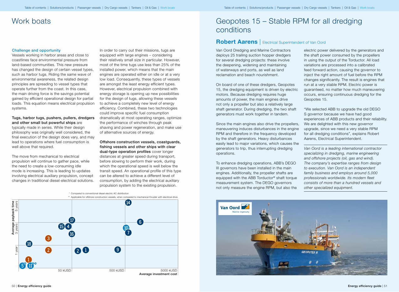
Geopotes 15 – Stable RPM for all dredging conditions
Robert Aarens | Electrical Superintendent of Van Oord
Van Oord Dredging and Marine Contractors deploys 25 trailing suction hopper dredgers for several dredging projects: these involve the deepening, widening and maintaining of waterways and ports, as well as land reclamation and beach nourishment.
On board of one of these dredgers, Geopotes 15, the dredging equipment is driven by electric motors. Because dredging requires huge amounts of power, the main engines drive not only a propeller but also a relatively large shaft generator. During dredging, the two shaft generators must work together in tandem.
Since the main engines also drive the propellers, maneuvering induces disturbances in the engine RPM and therefore in the frequency developed by the shaft generators. Heavy disturbances easily lead to major variations, which causes the generators to trip, thus interrupting dredging operations.
To enhance dredging operations, ABB’s DEGO III governors have been installed in the main engines. Additionally, the propeller shafts are equipped with the ABB Torductor® shaft torque measurement system. The DEGO governors not only measure the engine RPM, but also the
electric power delivered by the generators and the shaft power consumed by the propellers in using the output of the Torductor. All load variations are processed into a calibrated feed forward action, causing the governor to inject the right amount of fuel before the RPM changes significantly. The result is engines that run at a very stable RPM. Electric power is guaranteed, no matter how much maneuvering occurs, ensuring continuous dredging for the Geopotes 15.
“We selected ABB to upgrade the old DEGO S governor because we have had good experiences of ABB products and their reliability. We are delighted with this new governor upgrade, since we need a very stable RPM for all dredging conditions”, explains Robert Aarens, Electrical Superintendent.
Van Oord is a leading international contractor specializing in dredging, marine engineering and offshore projects (oil, gas and wind). The company’s expertise ranges from design to execution. Van Oord is an independent family business and employs around 5,000 professionals worldwide. Its modern fleet consists of more than a hundred vessels and other specialized equipment.
Table of contents | Solutions/products | Passenger vessels | Dry Cargo vessels | Tankers | Oil & Gas | Work boats Table of contents | Solutions/products | Passenger vessels | Dry Cargo vessels | Tankers | Oil & Gas | Work boats
52 | Energy efficiency guide Energy efficiency guide | 53
Solution overviews
5Table of contents | Solutions/products | Passenger vessels | Dry Cargo vessels | Tankers | Oil & Gas | Work boats Table of contents | Solutions/products | Passenger vessels | Dry Cargo vessels | Tankers | Oil & Gas | Work boats
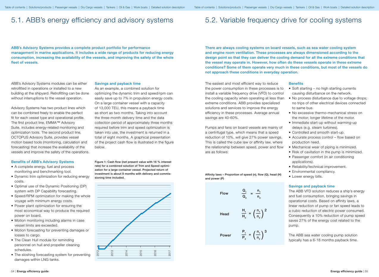
Flow
Head
Power
Q1
Q2
n1
n2
=
n1
n2
P1
P2
3= ( )
n1
n2
H1
H2
2= ( )
54 | Energy efficiency guide Energy efficiency guide | 55
5.1. ABB’s energy efficiency and advisory systems
ABB’s Advisory Systems provides a complete product portfolio for performance management in marine applications. It includes a wide range of products for reducing energy consumption, increasing the availability of the vessels, and improving the safety of the whole fleet of vessels.
ABB’s Advisory Systems modules can be either retrofitted in operations or installed to a new building at the shipyard. Retrofitting can be done without interruptions to the vessel operation.
Advisory Systems has two product lines which can be combined freely to enable the perfect fit for each vessel type and operational profile. The first product line, EMMA™ Advisory Suite, includes energy-related monitoring and optimization tools. The second product line, OCTOPUS Advisory Suite, provides vessel motion based tools (monitoring, calculation and forecasting) that increase the availability of the vessels and improve the safety of the operations.
Benefits of ABB’s Advisory Systems• A complete energy, fuel and process
monitoring and benchmarking tool.• Dynamic trim optimization for reducing energy
costs.• Optimal use of the Dynamic Positioning (DP)
system with DP Capability forecasting.• Speed/RPM optimization for making the whole
voyage with minimum energy costs.• Power plant optimization for ensuring the
most economical way to produce the required power on board.
• Motion monitoring including alarms in case vessel limits are exceeded.
• Motion forecasting for preventing damages or losses to cargo.
• The Clean Hull module for reminding personnel on hull and propeller cleaning schedules.
• The sloshing forecasting system for preventing damages within LNG tanks.
Savings and payback timeAs an example, a combined solution for optimizing the dynamic trim and speed/rpm can easily save up to 7% in propulsion energy costs. On a large container vessel with a capacity of 13,000 TEU, this means a payback time as short as two months. Taking into account the three-month delivery time and the data collection period of approximately three months required before trim and speed optimization is taken into use, the investment is returned in a total of eight months. A graphical presentation of the project cash flow is illustrated in the figure below.
Figure 1: Cash flow (net present value with 16 % interest rate) for a combined solution of Trim and Speed optimi-zation for a large container vessel. Projected return of investment is about 8 months with delivery and commis-sioning time included.
2012
2013
2014
2015
2016
2017
There are always cooling systems on board vessels, such as sea water cooling system and engine room ventilation. These processes are always dimensioned according to the design point so that they can deliver the cooling demand for all the extreme conditions that the vessel may operate in. However, how often do these vessels operate in these extreme conditions? Some of them operate very much in these conditions, but most of the vessels do not approach these conditions in everyday operation.
5.2. Variable frequency drive for cooling systems
The easiest and most efficient way to reduce the power consumption in these processes is to install a variable frequency drive (VFD) to control the cooling capacity when operating at less than extreme conditions. ABB provides specialized solutions and services to improve the energy efficiency in these processes. Average annual savings are 40-60%.
Pumps and fans on board vessels are mainly of a centrifugal type, which means that a speed reduction of 10%, will give 27% power savings. This is called the cube law or affinity law, where the relationship between speed, power and flow are as follows:
Benefits• Soft starting – no high starting currents
causing disturbance on the network.• No process disturbance due to voltage drops;
no trips of other electrical devices connected to same bus.
• No excessive thermo-mechanical stress on the motor; longer lifetime of the motor.
• Immediate start-up without warming-up delays (e.g. steam turbines).
• Controlled and smooth start-up.• Accurate process control – flow based on
production need.• Mechanical wear of piping is minimized.• Risk of cavitation in the pump is minimized.• Passenger comfort (in air conditioning
applications).• Reliability/technical improvement.• Environmental compliancy.• Lower energy bills.
Savings and payback timeThe ABB VFD solution reduces a ship’s energy and fuel consumption, bringing savings in operational costs. Based on affinity laws, a linear reduction of pump or fan speed leads to a cubic reduction of electric power consumed. Consequently a 10% reduction of pump speed saves 27% of the energy cost related to the pump.
The ABB sea water cooling pump solution typically has a 6-18 months payback time.
Affinity laws – Proportion of speed (n), flow (Q), head (H) and power (P)
Table of contents | Solutions/products | Passenger vessels | Dry Cargo vessels | Tankers | Oil & Gas | Work boats | Detailed solution description Table of contents | Solutions/products | Passenger vessels | Dry Cargo vessels | Tankers | Oil & Gas | Work boats | Detailed solution description
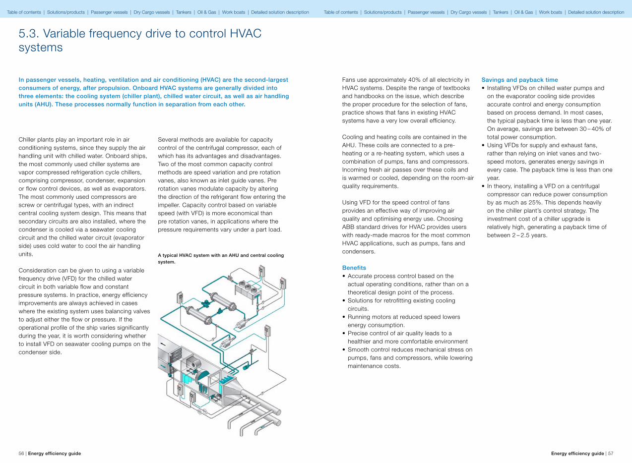
56 | Energy efficiency guide Energy efficiency guide | 57
5.3. Variable frequency drive to control HVAC systems
In passenger vessels, heating, ventilation and air conditioning (HVAC) are the second-largest consumers of energy, after propulsion. Onboard HVAC systems are generally divided into three elements: the cooling system (chiller plant), chilled water circuit, as well as air handling units (AHU). These processes normally function in separation from each other.
Chiller plants play an important role in air conditioning systems, since they supply the air handling unit with chilled water. Onboard ships, the most commonly used chiller systems are vapor compressed refrigeration cycle chillers, comprising compressor, condenser, expansion or flow control devices, as well as evaporators. The most commonly used compressors are screw or centrifugal types, with an indirect central cooling system design. This means that secondary circuits are also installed, where the condenser is cooled via a seawater cooling circuit and the chilled water circuit (evaporator side) uses cold water to cool the air handling units.
Consideration can be given to using a variable frequency drive (VFD) for the chilled water circuit in both variable flow and constant pressure systems. In practice, energy efficiency improvements are always achieved in cases where the existing system uses balancing valves to adjust either the flow or pressure. If the operational profile of the ship varies significantly during the year, it is worth considering whether to install VFD on seawater cooling pumps on the condenser side.
Several methods are available for capacity control of the centrifugal compressor, each of which has its advantages and disadvantages. Two of the most common capacity control methods are speed variation and pre rotation vanes, also known as inlet guide vanes. Pre rotation vanes modulate capacity by altering the direction of the refrigerant flow entering the impeller. Capacity control based on variable speed (with VFD) is more economical than pre rotation vanes, in applications where the pressure requirements vary under a part load.
A typical HVAC system with an AHU and central cooling system.
Fans use approximately 40% of all electricity in HVAC systems. Despite the range of textbooks and handbooks on the issue, which describe the proper procedure for the selection of fans, practice shows that fans in existing HVAC systems have a very low overall efficiency.
Cooling and heating coils are contained in the AHU. These coils are connected to a pre-heating or a re-heating system, which uses a combination of pumps, fans and compressors. Incoming fresh air passes over these coils and is warmed or cooled, depending on the room-air quality requirements.
Using VFD for the speed control of fans provides an effective way of improving air quality and optimising energy use. Choosing ABB standard drives for HVAC provides users with ready-made macros for the most common HVAC applications, such as pumps, fans and condensers.
Benefits• Accurate process control based on the
actual operating conditions, rather than on a theoretical design point of the process.
• Solutions for retrofitting existing cooling circuits.
• Running motors at reduced speed lowers energy consumption.
• Precise control of air quality leads to a healthier and more comfortable environment
• Smooth control reduces mechanical stress on pumps, fans and compressors, while lowering maintenance costs.
Savings and payback time• Installing VFDs on chilled water pumps and
on the evaporator cooling side provides accurate control and energy consumption based on process demand. In most cases, the typical payback time is less than one year. On average, savings are between 30 – 40% of total power consumption.
• Using VFDs for supply and exhaust fans, rather than relying on inlet vanes and two-speed motors, generates energy savings in every case. The payback time is less than one year.
• In theory, installing a VFD on a centrifugal compressor can reduce power consumption by as much as 25%. This depends heavily on the chiller plant’s control strategy. The investment cost of a chiller upgrade is relatively high, generating a payback time of between 2 – 2.5 years.
Table of contents | Solutions/products | Passenger vessels | Dry Cargo vessels | Tankers | Oil & Gas | Work boats | Detailed solution description Table of contents | Solutions/products | Passenger vessels | Dry Cargo vessels | Tankers | Oil & Gas | Work boats | Detailed solution description

58 | Energy efficiency guide Energy efficiency guide | 59
5.4. Winch control with variable frequency drive
Deck winches are commonly used on board today’s ships. Traditionally the marine winch market has been dominated by hydraulic systems and three-speed direct-on-line electrical systems. Both systems have their drawbacks. The hydraulic system requires a significant amount of space, while the oil used can constitute an environmental hazard. The three-speed electrical system has limited speed control, resulting in mechanical wear and coarse winch operation.
ABB’s winch control program enables the ABB variable frequency drive (VFD) range, rated from 0.55 kW to 5,600 kW to be used in different winching control configurations found on board ships, offshore oil or gas platforms and in harbors.
ABB variable frequency drives are certified for marine applications, enabling smooth stepless speed and torque control of anchor winches, mooring winches, Ro-Ro quarter ramp winches and towing winches. Benefits• The ideal solution for retrofits – the existing
winch motor, motor cable and operator control can be reused.
• Space saving on the deck – simplified winch arrangement.
• Lower noise level.• Reduced maintenance costs - Soft starting
reduces startup current peaks. Smooth stepless speed and torque control reduce stress on the whole mooring system.
• DTC (Direct Torque Control) eliminates the need for a pulse encoder, increasing the reliability of the winch system.
• Safe and accurate anchor and mooring winch control throughout the whole speed range.
• Cost reduction compared to closed loop systems.
• Environmentally friendly solution – Oil-free operation with fully electronic equipment.
• Reduction of mechanical wear.
• External programmable logic controller (PLC) not needed because the winch control program includes winch operation and protection functions.
• Multi I/O functionality allowing three different control stands to be connected directly to the drive.
• Anchor-in or anchor-slowdown protection reduces the speed as the anchor approaches its end position. Slip protection operates between the winch drum and winch motor.
• The peak torque protection in hand-mooring function detects severe tightening of the rope enabling immediate speed adjustment to protect the rope and the winch system from overload.
• Mechanical brake control with torque memory.• Easy start-up and maintenance of drive
system.• Adjustable auto-mooring provides accurate
rope tension control and eliminates the need for load cells on the ropes.
5.5. Onboard DC Grid
ABB delivers motors and drives from the smallest to the largest ones used in propulsion systems. These motors and drives can be used to simplify and improve the power plant of the vessel.
Benefits for the shipyard and designers• More flexible placement of electric
components.• Reduced footprint and up to 30% weight
saving of electrical equipment. • Less cabling and connections, thanks to the
use of bus ducts and fewer components.
Although the use of bus ducts is a relatively new type of installation work for many shipyards, there are several benefits to using them. For example, reduced cross section, no bending radius, and significant reduction of fire load compared to traditional cables.
SavingsAn Onboard DC Grid can reduce the equipment footprint and weight by up to 30%, and can reduce fuel consumption and emissions by up to 20%.
Imagine a ship which has an efficient and modern propulsion system. It is electric, featuring state-of-the-art equipment. Now, take this vessel and increase the efficiency by up to 20% and reduce the footprint of electrical equipment by up to 30%. Add to that the freedom to integrate and combine different energy sources, including renewables, gas and diesel, and flexibility to place system components around the vessel.
This is the ABB Onboard DC Grid, a solution designed for all types of vessels which have a low voltage power plant.
Benefits for the ship owner• Up to 20% fuel saving when taking full
advantage of all of the features, including energy storage and variable speed engines.
• Reduced methane slip for gas engines at low load.
• Reduced maintenance of engines as a consequence of more efficient operation.
• Improved dynamic response by using energy storage, which may give a better dynamic positioning (DP) performance with lower fuel consumption or more accurate positioning.
• Increased space for payload due to the lower footprint of electrical plant.
• More functional vessel layout because electrical components can be placed more flexibly.
• A system platform that enables simple “plug and play” retrofitting possibilities to adapt to future energy sources.
Table of contents | Solutions/products | Passenger vessels | Dry Cargo vessels | Tankers | Oil & Gas | Work boats | Detailed solution description Table of contents | Solutions/products | Passenger vessels | Dry Cargo vessels | Tankers | Oil & Gas | Work boats | Detailed solution description
60 | Energy efficiency guide Energy efficiency guide | 61
5.6. Hybrid power plants enabled by batteries
Facing a growing demand for higher power plant efficiency, reduced fuel consumption and lower emission levels, the marine industry is evaluating concepts based on the use of hybrid power plants with energy storage systems.
With the availability of high-power and energy dense batteries, such systems are now being considered as a possible additional and/or alternative power source to diesel generator sets for on board electrical power plants. Load sharing has to be controlled, especially when the battery system is operating in parallel with other power sources.
Hybrid systems will reduce the energy consumption. When an offshore supply vessel is operating on dynamic positioning, the fuel saving potential is significant. When in harbor, the vessel should be able to simply use the power stored in the batteries, which again will have a positive impact on the environment. Additional benefits are related to the reduction in the machinery maintenance cost and in lower noise and vibrations.
Ferries operating on short-distance routes, such as river and fjord crossing ferries, can operate fully battery driven with fast charging at both ends or only at one end, depending on the distance of the crossing. A hybrid version, where the vast majority of the energy is delivered by the batteries supported with onboard diesel generators can also be considered.
Use of batteries as a source of energy brings in a big portion of flexibility in every day operation.The objective with using batteries may be: • An energy backup source which is
instantaneously available for the equipment essential to safety and operations, in case of main power supply interruption.
• Overall efficiency improvement by temporary storage of braking energy and smoothening of power consumption from power network in case of process dependent fast load fluctuation (load shaving).
• Reducing frequency variation in network by avoiding fast load gradients of diesel generators.
• Low emission power plant by use of hybrid system; a combination of combustion engine and electrical energy storage system, or pure electrical power plant with electrical energy storage systems.
Benefits• Reduced fuel consumption• Reduced emissions• Improved dynamic response of the power
plant• Increased power plant availability due to the
instantaneous availability of energy backup source
5.7. Variable frequency drive for shaft generator (PTO/PTI)
Shaft generators are commonly used to produce electrical power for the ship’s network, in vessels equipped with a conventional propulsion system, where a mechanical shaft is driven by a slow or medium speed engine.
System design often restricts how and under what conditions the shaft generator can be used to generate electricity since, because most systems lack frequency control, such power generation depends on the ship maintaining a constant speed.
In vessels equipped with a fixed pitch propeller (FPP), this generally means that the shaft generator can only be used on open seas when the vessel is operating at its design speed, which does not allow a flexible use of the shaft generator.
In the case of vessels equipped with a controllable pitch propeller (CPP), more hydrodynamic efficient combinator control mode cannot be used together with the shaft generator, due to the fact that this would generate incorrect frequency into the electrical network.
A shaft generator is the most practical solution when equipped with a variable frequency drive (VFD). By this addition the shaft generator may be used on the wider speed range and often the meaningful part of combinator speed range is covered. The operational flexibility of an existing shaft generator can also be significantly improved, by retrofitting it with a VFD for controlling the shaft generator’s output.
BenefitsUsing a shaft generator with a VFD for power production is economical, environment-friendly and provides a range of advantages. This is not limited to new builds – major improvements can
also be made to the efficiency and operational flexibility of an existing shaft generator system by retrofitting it with a VFD.
• A power source which, under most conditions, generates much cheaper energy than auxiliary diesel generator sets
• With CPP propulsion, VFD installation allows efficient use of combinator mode instead of fixed speed operation, thus reducing propeller losses significantly on partial propeller loading conditions.
• With a VFD, it is possible to utilize the shaft generator at a wide range of main engine RPMs, enabling operational flexibility: – Nominal voltage and frequency output from the shaft generator can be maintained
– For improved efficiency, main engine shaft power can be used to produce electricity over the entire operating area,
– Generating power for ship network via the shaft generator alone reduces the need to use auxiliary generators
– Flexibility in PTI/PTO function – Parallel running with generator sets is possible
– Increased efficiency from optimal operation of the propeller with CPP
– Lower noise levels – Improved energy efficiency reduces emissions
Savings Although the benefits vary from vessel to vessel and are dependent on the operating profile, the payback time can be short and the reduction in the vessel’s environmental footprint significant.
Table of contents | Solutions/products | Passenger vessels | Dry Cargo vessels | Tankers | Oil & Gas | Work boats | Detailed solution description Table of contents | Solutions/products | Passenger vessels | Dry Cargo vessels | Tankers | Oil & Gas | Work boats | Detailed solution description
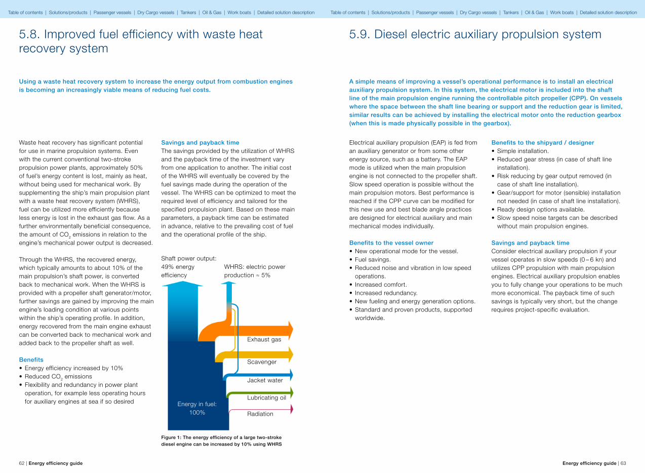
62 | Energy efficiency guide Energy efficiency guide | 63
5.8. Improved fuel efficiency with waste heat recovery system
Using a waste heat recovery system to increase the energy output from combustion engines is becoming an increasingly viable means of reducing fuel costs.
Waste heat recovery has significant potential for use in marine propulsion systems. Even with the current conventional two-stroke propulsion power plants, approximately 50% of fuel’s energy content is lost, mainly as heat, without being used for mechanical work. By supplementing the ship’s main propulsion plant with a waste heat recovery system (WHRS), fuel can be utilized more efficiently because less energy is lost in the exhaust gas flow. As a further environmentally beneficial consequence, the amount of CO2 emissions in relation to the engine’s mechanical power output is decreased.
Through the WHRS, the recovered energy, which typically amounts to about 10% of the main propulsion’s shaft power, is converted back to mechanical work. When the WHRS is provided with a propeller shaft generator/motor, further savings are gained by improving the main engine’s loading condition at various points within the ship’s operating profile. In addition, energy recovered from the main engine exhaust can be converted back to mechanical work and added back to the propeller shaft as well.
Benefits• Energy efficiency increased by 10%• Reduced CO2 emissions• Flexibility and redundancy in power plant
operation, for example less operating hours for auxiliary engines at sea if so desired
Savings and payback timeThe savings provided by the utilization of WHRS and the payback time of the investment vary from one application to another. The initial cost of the WHRS will eventually be covered by the fuel savings made during the operation of the vessel. The WHRS can be optimized to meet the required level of efficiency and tailored for the specified propulsion plant. Based on these main parameters, a payback time can be estimated in advance, relative to the prevailing cost of fuel and the operational profile of the ship.
Figure 1: The energy efficiency of a large two-stroke diesel engine can be increased by 10% using WHRS
Shaft power output: 49% energy efficiency
WHRS: electric power production ≈ 5%
Exhaust gas
Scavenger
Jacket water
Lubricating oil
Radiation
Energy in fuel:100%
5.9. Diesel electric auxiliary propulsion system
A simple means of improving a vessel’s operational performance is to install an electrical auxiliary propulsion system. In this system, the electrical motor is included into the shaft line of the main propulsion engine running the controllable pitch propeller (CPP). On vessels where the space between the shaft line bearing or support and the reduction gear is limited, similar results can be achieved by installing the electrical motor onto the reduction gearbox (when this is made physically possible in the gearbox).
Electrical auxiliary propulsion (EAP) is fed from an auxiliary generator or from some other energy source, such as a battery. The EAP mode is utilized when the main propulsion engine is not connected to the propeller shaft. Slow speed operation is possible without the main propulsion motors. Best performance is reached if the CPP curve can be modified for this new use and best blade angle practices are designed for electrical auxiliary and main mechanical modes individually.
Benefits to the vessel owner• New operational mode for the vessel.• Fuel savings.• Reduced noise and vibration in low speed
operations.• Increased comfort.• Increased redundancy.• New fueling and energy generation options.• Standard and proven products, supported
worldwide.
Benefits to the shipyard / designer• Simple installation.• Reduced gear stress (in case of shaft line
installation).• Risk reducing by gear output removed (in
case of shaft line installation).• Gear/support for motor (sensible) installation
not needed (in case of shaft line installation).• Ready design options available.• Slow speed noise targets can be described
without main propulsion engines.
Savings and payback timeConsider electrical auxiliary propulsion if your vessel operates in slow speeds (0 – 6 kn) and utilizes CPP propulsion with main propulsion engines. Electrical auxiliary propulsion enables you to fully change your operations to be much more economical. The payback time of such savings is typically very short, but the change requires project-specific evaluation.
Table of contents | Solutions/products | Passenger vessels | Dry Cargo vessels | Tankers | Oil & Gas | Work boats | Detailed solution description Table of contents | Solutions/products | Passenger vessels | Dry Cargo vessels | Tankers | Oil & Gas | Work boats | Detailed solution description
64 | Energy efficiency guide Energy efficiency guide | 65
5.10. Small power propulsion solution
As environmental issues have become an important factor for many of us, the need for electrical propulsion solutions in the smaller propulsion power ranges has become a very common request for ABB Marine.
Traditionally, the additional weight from the power generation and the equipment size increase due to slower main engine revolutions have been a limiting design criteria in the utilization of electrical propulsion systems (the execution limit has been somewhere between 20 - 40 meters of the vessel length), but nowadays we are often ready to accept some performance reductions for the sake of environmentally healthier operations. Such a mindset change is leading to the utilization of electrical propulsion in smaller and smaller vessels, ranging from leisure boats to fishing vessels.
Another design-related obstacle in the utilization of small electrical propulsion systems has been the lack of solutions available from the global propulsion system manufacturers who are delivering these systems to the larger vessels. Such companies, including also ABB Marine, often work as system suppliers, being responsible for the total design and scope of the system. These companies have the best experience, know-how, service network and practices to build working solutions for large
vessels and this expertise should also be made available to smaller vessels. Additionally, the propulsion system providers are often large companies, looking for big projects. This has not been favorable for smaller vessels, where the design task of the electrical propulsion system is equally demanding as with larger vessels, but the project size is too small to be of interest to many of the system providers. As a result, the electrical propulsion system market for smaller vessels has been dominated by all kinds of tailored solutions using components that are made for small series and are often supported only locally. This is a pity for the vessel operators, who – even though their vessel size is smaller – often operate their ships in various areas, requiring services and support at the same scale as larger ship operators.
As a market leader in many various vessel types, ABB wants to introduce a systematic and standard product portfolio for small electrical propulsion systems. We want to make the same electrical propulsion options that are already in use in larger vessels available also to smaller vessels.
Benefits for the owner• Possibility to run one, two or more common
engines with two propellers with relatively good efficiency throughout the vessel’s speed range, especially at lower speeds.
• New operational modes for the vessel.• Fuel savings.• Reduced noise and vibration in low speed
operations.• Increased comfort.• Increased redundancy.• New fueling and energy generation options.• Standard and proven products, supported
worldwide.• New sources of energy can be utilized.
Benefits for the shipyard / designer• Day 1 material availability for the main
component dimensions.• Support from the system designers.• Simple installation.• Hull design does not need to follow the
propulsion engine and shafting (the main engines do not have to be side-by-side either).
• Flexible location of equipment.• No gear boxes.• Industrial risk levels due to standard product
offering.• Slow speed noise targets can be achieved
easier with small engines.
Savings and payback timeConsider electrical propulsion option if your vessel does not follow the pattern of continuous full speed operations. Diesel-electrical propulsion system makes it possible for the vessel to stay moving longer, for longer distances and with a higher comfort level. This makes diesel-electrical propulsion system a different concept compared to the noisy but fast-moving mechanical version and comparing these two in parallel a bit of a challenge.
When the concepts were compared in the operation profile of a less than 50-meter yacht, the study outcome reflected the same result as in the whole small vessel segment: compared to mechanical propulsion, electrical propulsion brings savings at the same cruising speed, extends the cruising time (at 25 Kn from 15 hours to 17,7 hours) but the vessel’s maximum performance (top speed) was reduced from 31 Kn to 27 Kn in order to keep the weight within allowed limits. Therefore the savings by the concept selection are clear and have a defined payback time, but they also require the owner to make selections regarding the vessel’s operational requirements.
Table of contents | Solutions/products | Passenger vessels | Dry Cargo vessels | Tankers | Oil & Gas | Work boats | Detailed solution description Table of contents | Solutions/products | Passenger vessels | Dry Cargo vessels | Tankers | Oil & Gas | Work boats | Detailed solution description

66 | Energy efficiency guide Energy efficiency guide | 67
5.11. Azipod® propulsion
Efficiency and availabilityAzipod technology was introduced in 1990. The first cruise vessel installation on the Fantasy-class vessel Elation in 1998 showed remarkably positive results with high efficiency and excellent maneuverability. The new technology provided ship designers with greater freedom to optimize the ship’s general arrangement.
After processing further knowledge from experience and getting a better understanding of the system’s behavior in operation, the scope of development was widened to cover larger systems.
Design improvementsAt first the improvements were mainly concentrated on shaft bearings and seals. While the basic mechanical design remained the same, the focus was to provide improved lubrication conditions and to improve seals to prevent any leakages into the lube oil or into the sea.
After collecting several years of operational experience with wider knowledge of system behavior, improvements were broadened to include processes like better control of manufacturing, delivery and operational processes, and general quality control.
Time for redesignAfter several generations of updates from the original design, it was seen that a concurrent redesign would be necessary to be able to combine all identified improvement ideas. The first such development project addressed the larger open water unit series, which was subsequently given the identifying type code Azipod XO where X stands for “next generation Azipod” and O means that it is mainly made for vessels that will operate in open water conditions. In this research and development project ABB Marine decided to utilize well-known, proven technologies for components
and design. As an example of the latter, sliding bearings were selected for thrust bearings.
The outer shaft seal was also completely redesigned to provide similar benefits: reliability and maintainability. The seal system enables advanced condition monitoring to a degree not seen elsewhere in the market.
For larger models the seal can be changed from inside the pod. The seal is designed for a five-year lifetime and to be replaced during normal dry-dockings, but in case of an emergency situation this can also be done with the vessel afloat.
The fully electric steering gear was originally designed for smaller Azipod sizes, but it was the right time to introduce it for larger open water unit sizes to replace conventional electro-hydraulic steering gear. The main reasons for this step were that it reduced energy consumption and noise, as well as cutting the amount of oil in the installation, in order to make it more environmentally friendly. Electric steering gear is now installed on recent Azipod deliveries for open water conditions.
Improved fuel efficiencyThe propulsion efficiency of Azipod propulsion, when originally installed on cruise ship Elation back in 1997, improved by some 9 percent, when comparing identical sisterships with traditional shaftlines. Since then, the propulsion efficiency has been improved by several steps in design optimization.
One major hydrodynamic improvement was gained early by installing a fin under the Azipod to reduce rotational flow losses generated by the propeller. In the next steps, the Azipod strut design was modified by making it slimmer and more optimal for operation in the propulsion environment. Finally, with the Azipod XO, the
propeller hub and motor module diameters were reduced and the unIt is entire hull was optimized with the help of CFD and model testing.
During 2011, ABB introduced an additional package to improve Azipod propulsion efficiency further. This package consists of an asymmetric lower fin and crossed plates (X-tail) that are integrated in the aft cone. The asymmetric lower fin will improve efficiency up to 1 percent by reducing the losses from the propulsion system and the X-tail will further increase efficiency by up to 1.5 percent by reducing the rotational flow losses at the aft cone section. These changes can also be made as a retrofit installation on open water units. The first retrofit work with asymmetric fin and X-tail was done in 2011 during the vessel’s normal dry docking.
Also in 2011, ABB launched a method of optimizing the energy efficiency of Azipod installations on board vessels. This was based on the finding that further fuel consumption savings can be reached by optimizing the toe (steering) angle of the Azipod units dynamically, in addition to the angle optimization already undertaken at the vessel design stage. This package has the acronym ADO from the words “Azipod Dynamic Optimizer”. Fuel consumption is estimated to be reduced further by up to 1.5 percent using ADO.
The overall improvement in propulsion efficiency has been above 10 percent over the course of the existence of the Azipod, with a more than 20 percent gain when compared to the shaftlines being used back in the mid 1990s. However, it is fair to acknowledge that there have also been improvements in shaftline propulsion during this time. Even so, a recent comparison test at Marin showed that Azipod propulsion compared to a fixed shaftline propulsion design still had a 6 – 8 percent lead what regards to propulsion efficiency. Furthermore, these tests were made
before the introduction of asymmetric fin, X-tail and ADO, which can improve the efficiency of the Azipod system overall by up to four percent.
Operation experienceWith regards to fuel savings and ship maneuverability, the expectations set by ship operators have typically been fulfilled or exceeded by the Azipod. Ship captains in particular have expressed satisfaction with the ease of operation and the maneuverability of their ships. Concerning energy efficiency, some operators have claimed fuel savings of more than 20 percent, compared with their vessels operating with conventional propulsion.
Over 8,5 million operating hours with Azipod propulsion have resulted in the largest pool of experience in how podded propulsion systems should be designed, used and maintained for trouble-free reliable operation.
During the two decades ABB has established a unique position being the only company that has in-depth and in-house product and integration knowledge, with a responsibility covering the whole concept from hydrodynamics, mechanics, electronics, cooling to operating, maintenance and services, as well as the integration of the complete electrical and control system.
Nowadays, Azipod propulsion and thruster units are designed for five years dry-docking and maintenance intervals. For some applications a longer maintenance interval of even up to 10 years has proven supportable. This conclusion is based on results drawn from a well documented operational and maintenance history. Today, there are some 100 vessels using Azipod propulsion. It has been selected for a wide range of ship types and operations; such as cruise ships, icebreakers and ice-going cargo vessels, ferries, megayachts, offshore supply vessels, research vessels, wind turbine installation vessels and drilling rigs.
Table of contents | Solutions/products | Passenger vessels | Dry Cargo vessels | Tankers | Oil & Gas | Work boats | Detailed solution description Table of contents | Solutions/products | Passenger vessels | Dry Cargo vessels | Tankers | Oil & Gas | Work boats | Detailed solution description
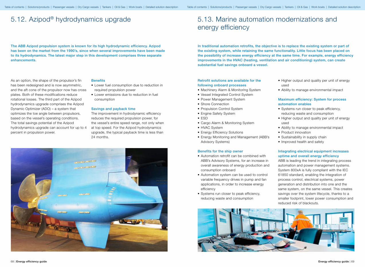
68 | Energy efficiency guide Energy efficiency guide | 69
5.12. Azipod® hydrodynamics upgrade
The ABB Azipod propulsion system is known for its high hydrodynamic efficiency. Azipod has been on the market from the 1990’s, since when several improvements have been made to its hydrodynamics. The latest major step in this development comprises three separate enhancements.
As an option, the shape of the propulsor’s fin has been redesigned and is now asymmetric, and the aft cone of the propulsor now has cross plates. Both of these modifications reduce rotational losses. The third part of the Azipod hydrodynamics upgrade comprises the Azipod Dynamic Optimizer (ADO) – a system that optimizes the toe angle between propulsors, based on the vessel’s operating conditions. The total savings potential of the Azipod hydrodynamics upgrade can account for up to 4 percent in propulsion power.
Benefits• Lower fuel consumption due to reduction in
required propulsion power• Lower emissions due to reduction in fuel
consumption
Savings and payback timeThe improvement in hydrodynamic efficiency reduces the required propulsion power, for the vessel’s entire speed range, not only when at top speed. For the Azipod hydrodynamics upgrade, the typical payback time is less than 24 months.
5.13. Marine automation modernizations and energy efficiency
In traditional automation retrofits, the objective is to replace the existing system or part of the existing system, while retaining the same functionality. Little focus has been placed on the possibility of increase energy efficiency at the same time. For example, energy efficiency improvements in the HVAC (heating, ventilation and air conditioning) system, can create substantial fuel savings onboard a vessel.
Retrofit solutions are available for the following onboard processes• Machinery Alarm & Monitoring System• Vessel Integrated Control System• Power Management System• Shore Connection• Propulsion Control System• Engine Safety System• ESD• Cargo Alarm & Monitoring System• HVAC System• Energy Efficiency Solutions• Energy Monitoring and Management (ABB’s
Advisory Systems)
Benefits for the ship owner• Automation retrofit can be combined with
ABB’s Advisory Systems, for an increase in overall awareness of energy production and consumption onboard
• Automation system can be used to control variable frequency drives in pump and fan applications, in order to increase energy efficiency
• Systems run closer to peak efficiency, reducing waste and consumption
• Higher output and quality per unit of energy used
• Ability to manage environmental impact
Maximum efficiency: System for process automation enables• Systems run closer to peak efficiency,
reducing waste and consumption• Higher output and quality per unit of energy
used• Ability to manage environmental impact• Product innovation • Sustainability in supply chain• Improved health and safety
Integrating electrical equipment increases uptime and overall energy efficiencyABB is leading the trend in integrating process automation and power management systems. System 800xA is fully compliant with the IEC 61850 standard, enabling the integration of process control, electrical systems, power generation and distribution into one and the same system, on the same vessel. This creates savings over the system lifecycle, thanks to a smaller footprint, lower power consumption and reduced risk of blackouts.
Table of contents | Solutions/products | Passenger vessels | Dry Cargo vessels | Tankers | Oil & Gas | Work boats | Detailed solution description Table of contents | Solutions/products | Passenger vessels | Dry Cargo vessels | Tankers | Oil & Gas | Work boats | Detailed solution description
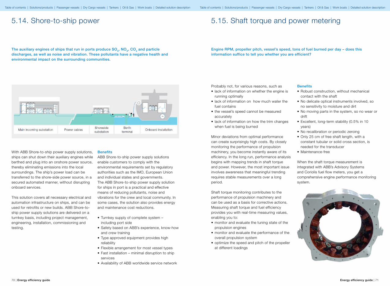
70 | Energy efficiency guide Energy efficiency guide | 71
5.14. Shore-to-ship power
The auxiliary engines of ships that run in ports produce SOX, NOX, CO2 and particle discharges, as well as noise and vibration. These pollutants have a negative health and environmental impact on the surrounding communities.
With ABB Shore-to-ship power supply solutions, ships can shut down their auxiliary engines while berthed and plug into an onshore power source, thereby eliminating emissions into the local surroundings. The ship’s power load can be transferred to the shore-side power source, in a secured automated manner, without disrupting onboard services.
This solution covers all necessary electrical and automation infrastructure on ships, and can be used for retrofits or new builds. ABB Shore-to-ship power supply solutions are delivered on a turnkey basis, including project management, engineering, installation, commissioning and testing.
BenefitsABB Shore-to-ship power supply solutions enable customers to comply with the environmental requirements set by regulatory authorities such as the IMO, European Union and individual states and governments.The ABB Shore-to-ship power supply solution for ships in port is a practical and effective means of reducing pollutants, noise and vibrations for the crew and local community. In some cases, the solution also provides energy and maintenance cost reductions.
• Turnkey supply of complete system – including port side
• Safety based on ABB’s experience, know-how and crew training
• Type approved equipment provides high reliability
• Flexible arrangement for most vessel types• Fast installation – minimal disruption to ship
services• Availability of ABB worldwide service network
5.15. Shaft torque and power metering
Engine RPM, propeller pitch, vessel’s speed, tons of fuel burned per day – does this information suffice to tell you whether you are efficient?
Benefits• Robust construction, without mechanical
contact with the shaft• No delicate optical instruments involved, so
no sensitivity to moisture and dirt• No moving parts in the system, so no wear or
drift• Excellent, long-term stability (0.5% in 10
years)• No recalibration or periodic zeroing• Only 25 cm of free shaft length, with a
constant tubular or solid cross section, is needed for the transducer
• Maintenance-free
When the shaft torque measurement is integrated with ABB’s Advisory Systems and Coriolis fuel flow meters, you get a comprehensive engine performance monitoring system.
Probably not, for various reasons, such as• lack of information on whether the engine is
running optimally• lack of information on how much water the
fuel contains• the vessel’s speed cannot be measured
accurately • lack of information on how the trim changes
when fuel is being burned
Minor deviations from optimal performance can create surprisingly high costs. By closely monitoring the performance of propulsion machinery, you become instantly aware of its efficiency. In the long run, performance analysis begins with mapping trends in shaft torque and power. However, the most important issue involves awareness that meaningful trending requires stable measurements over a long period.
Shaft torque monitoring contributes to the performance of propulsion machinery and can be used as a basis for corrective actions. Measuring shaft torque and fuel efficiency provides you with real-time measuring values, enabling you to:• monitor and evaluate the tuning state of the
propulsion engines• monitor and evaluate the performance of the
overall propulsion system• optimize the speed and pitch of the propeller
at different loadings
Table of contents | Solutions/products | Passenger vessels | Dry Cargo vessels | Tankers | Oil & Gas | Work boats | Detailed solution description Table of contents | Solutions/products | Passenger vessels | Dry Cargo vessels | Tankers | Oil & Gas | Work boats | Detailed solution description
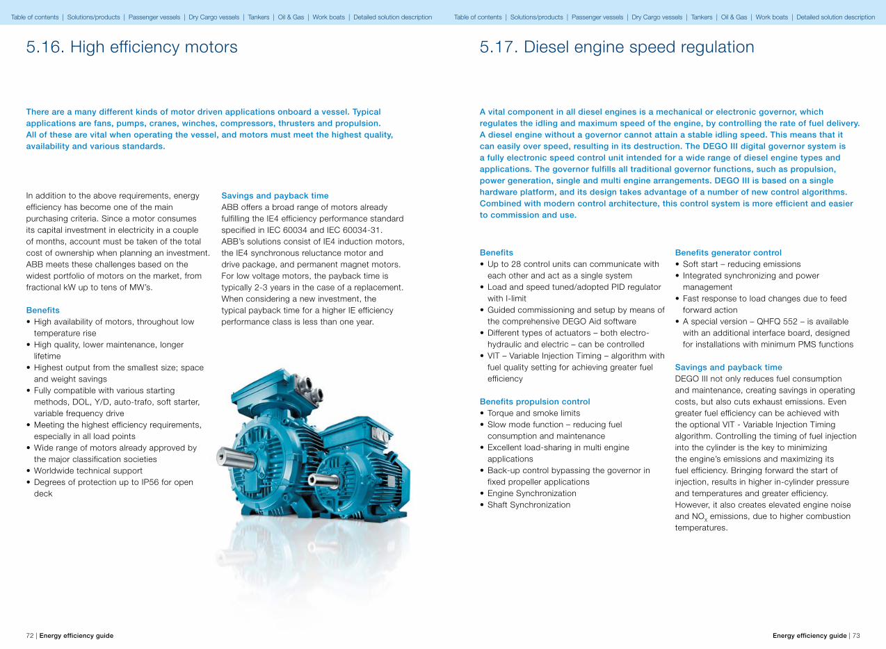
72 | Energy efficiency guide Energy efficiency guide | 73
5.16. High efficiency motors
There are a many different kinds of motor driven applications onboard a vessel. Typical applications are fans, pumps, cranes, winches, compressors, thrusters and propulsion. All of these are vital when operating the vessel, and motors must meet the highest quality, availability and various standards.
In addition to the above requirements, energy efficiency has become one of the main purchasing criteria. Since a motor consumes its capital investment in electricity in a couple of months, account must be taken of the total cost of ownership when planning an investment. ABB meets these challenges based on the widest portfolio of motors on the market, from fractional kW up to tens of MW’s.
Benefits• High availability of motors, throughout low
temperature rise• High quality, lower maintenance, longer
lifetime• Highest output from the smallest size; space
and weight savings• Fully compatible with various starting
methods, DOL, Y/D, auto-trafo, soft starter, variable frequency drive
• Meeting the highest efficiency requirements, especially in all load points
• Wide range of motors already approved by the major classification societies
• Worldwide technical support• Degrees of protection up to IP56 for open
deck
Savings and payback timeABB offers a broad range of motors already fulfilling the IE4 efficiency performance standard specified in IEC 60034 and IEC 60034-31. ABB’s solutions consist of IE4 induction motors, the IE4 synchronous reluctance motor and drive package, and permanent magnet motors. For low voltage motors, the payback time is typically 2-3 years in the case of a replacement. When considering a new investment, the typical payback time for a higher IE efficiency performance class is less than one year.
5.17. Diesel engine speed regulation
A vital component in all diesel engines is a mechanical or electronic governor, which regulates the idling and maximum speed of the engine, by controlling the rate of fuel delivery. A diesel engine without a governor cannot attain a stable idling speed. This means that it can easily over speed, resulting in its destruction. The DEGO III digital governor system is a fully electronic speed control unit intended for a wide range of diesel engine types and applications. The governor fulfills all traditional governor functions, such as propulsion, power generation, single and multi engine arrangements. DEGO III is based on a single hardware platform, and its design takes advantage of a number of new control algorithms. Combined with modern control architecture, this control system is more efficient and easier to commission and use.
Benefits • Up to 28 control units can communicate with
each other and act as a single system• Load and speed tuned/adopted PID regulator
with I-limit• Guided commissioning and setup by means of
the comprehensive DEGO Aid software• Different types of actuators – both electro-
hydraulic and electric – can be controlled• VIT – Variable Injection Timing – algorithm with
fuel quality setting for achieving greater fuel efficiency
Benefits propulsion control• Torque and smoke limits• Slow mode function – reducing fuel
consumption and maintenance• Excellent load-sharing in multi engine
applications• Back-up control bypassing the governor in
fixed propeller applications• Engine Synchronization• Shaft Synchronization
Benefits generator control• Soft start – reducing emissions• Integrated synchronizing and power
management• Fast response to load changes due to feed
forward action• A special version – QHFQ 552 – is available
with an additional interface board, designed for installations with minimum PMS functions
Savings and payback timeDEGO III not only reduces fuel consumption and maintenance, creating savings in operating costs, but also cuts exhaust emissions. Even greater fuel efficiency can be achieved with the optional VIT - Variable Injection Timing algorithm. Controlling the timing of fuel injection into the cylinder is the key to minimizing the engine’s emissions and maximizing its fuel efficiency. Bringing forward the start of injection, results in higher in-cylinder pressure and temperatures and greater efficiency. However, it also creates elevated engine noise and NOX emissions, due to higher combustion temperatures.
Table of contents | Solutions/products | Passenger vessels | Dry Cargo vessels | Tankers | Oil & Gas | Work boats | Detailed solution description Table of contents | Solutions/products | Passenger vessels | Dry Cargo vessels | Tankers | Oil & Gas | Work boats | Detailed solution description
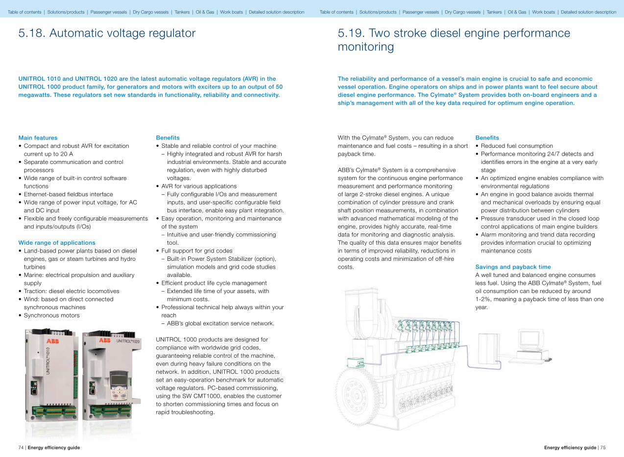
74 | Energy efficiency guide Energy efficiency guide | 75
5.18. Automatic voltage regulator
UNITROL 1010 and UNITROL 1020 are the latest automatic voltage regulators (AVR) in the UNITROL 1000 product family, for generators and motors with exciters up to an output of 50 megawatts. These regulators set new standards in functionality, reliability and connectivity.
Benefits• Stable and reliable control of your machine
– Highly integrated and robust AVR for harsh industrial environments. Stable and accurate regulation, even with highly disturbed voltages.
• AVR for various applications – Fully configurable I/Os and measurement inputs, and user-specific configurable field bus interface, enable easy plant integration.
• Easy operation, monitoring and maintenance of the system – Intuitive and user-friendly commissioning tool.
• Full support for grid codes – Built-in Power System Stabilizer (option), simulation models and grid code studies available.
• Efficient product life cycle management – Extended life time of your assets, with minimum costs.
• Professional technical help always within your reach – ABB’s global excitation service network.
UNITROL 1000 products are designed for compliance with worldwide grid codes, guaranteeing reliable control of the machine, even during heavy failure conditions on the network. In addition, UNITROL 1000 products set an easy-operation benchmark for automatic voltage regulators. PC-based commissioning, using the SW CMT1000, enables the customer to shorten commissioning times and focus on rapid troubleshooting.
Main features• Compact and robust AVR for excitation
current up to 20 A• Separate communication and control
processors • Wide range of built-in control software
functions• Ethernet-based fieldbus interface• Wide range of power input voltage, for AC
and DC input• Flexible and freely configurable measurements
and inputs/outputs (I/Os)
Wide range of applications• Land-based power plants based on diesel
engines, gas or steam turbines and hydro turbines
• Marine: electrical propulsion and auxiliary supply
• Traction: diesel electric locomotives• Wind: based on direct connected
synchronous machines• Synchronous motors
5.19. Two stroke diesel engine performance monitoring
The reliability and performance of a vessel’s main engine is crucial to safe and economic vessel operation. Engine operators on ships and in power plants want to feel secure about diesel engine performance. The Cylmate® System provides both on-board engineers and a ship’s management with all of the key data required for optimum engine operation.
With the Cylmate® System, you can reduce maintenance and fuel costs – resulting in a short payback time.
ABB’s Cylmate® System is a comprehensive system for the continuous engine performance measurement and performance monitoring of large 2-stroke diesel engines. A unique combination of cylinder pressure and crank shaft position measurements, in combination with advanced mathematical modeling of the engine, provides highly accurate, real-time data for monitoring and diagnostic analysis. The quality of this data ensures major benefits in terms of improved reliability, reductions in operating costs and minimization of off-hire costs.
Benefits• Reduced fuel consumption• Performance monitoring 24/7 detects and
identifies errors in the engine at a very early stage
• An optimized engine enables compliance with environmental regulations
• An engine in good balance avoids thermal and mechanical overloads by ensuring equal power distribution between cylinders
• Pressure transducer used in the closed loop control applications of main engine builders
• Alarm monitoring and trend data recording provides information crucial to optimizing maintenance costs
Savings and payback timeA well tuned and balanced engine consumes less fuel. Using the ABB Cylmate® System, fuel oil consumption can be reduced by around 1-2%, meaning a payback time of less than one year.
Table of contents | Solutions/products | Passenger vessels | Dry Cargo vessels | Tankers | Oil & Gas | Work boats | Detailed solution description Table of contents | Solutions/products | Passenger vessels | Dry Cargo vessels | Tankers | Oil & Gas | Work boats | Detailed solution description

76 | Energy efficiency guide Energy efficiency guide | 77
6Detailed solution descriptions
Table of contents | Solutions/products | Passenger vessels | Dry Cargo vessels | Tankers | Oil & Gas | Work boats Table of contents | Solutions/products | Passenger vessels | Dry Cargo vessels | Tankers | Oil & Gas | Work boats
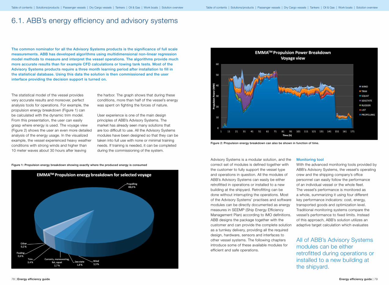
78 | Energy efficiency guide Energy efficiency guide | 79
6.1. ABB’s energy efficiency and advisory systems
The common nominator for all the Advisory Systems products is the significance of full scale measurements. ABB has developed algorithms using multidimensional non-linear regression model methods to measure and interpret the vessel operations. The algorithms provide much more accurate results than for example CFD calculations or towing tank tests. Most of the Advisory Systems products require a three month learning period after installation to fill in the statistical database. Using this data the solution is then commissioned and the user interface providing the decision support is turned on.
Figure 1: Propulsion energy breakdown showing exactly where the produced energy is consumed
The statistical model of the vessel provides very accurate results and moreover, perfect analysis tools for operations. For example, the propulsion energy breakdown (Figure 1) can be calculated with the dynamic trim model. From this presentation, the user can easily grasp where energy is used. The voyage view (Figure 2) shows the user an even more detailed analysis of the energy usage. In the visualized example, the vessel experienced heavy weather conditions with strong winds and higher than 10 meter waves about 30 hours after leaving
the harbor. The graph shows that during these conditions, more than half of the vessel’s energy was spent on fighting the forces of nature.
User experience is one of the main design principles of ABB’s Advisory Systems. The market has already seen many solutions that are too difficult to use. All the Advisory Systems modules have been designed so that they can be taken into full use with none or minimal training needs. If training is needed, it can be completed during the commissioning of the system.
Advisory Systems is a modular solution, and the correct set of modules is defined together with the customer to fully support the vessel type and operations in question. All the modules of ABB’s Advisory Systems can easily be either retrofitted in operations or installed to a new building at the shipyard. Retrofitting can be done without interrupting the operations. Most of the Advisory Systems’ practises and software modules can be directly documented as energy measures in SEEMP (Ship Energy Efficiency Management Plan) according to IMO definitions. ABB designs the package together with the customer and can provide the complete solution as a turnkey delivery, providing all the required design, hardware, sensors and interfaces to other vessel systems. The following chapters introduce some of these available modules for efficient and safe operations.
Monitoring toolWith the advanced monitoring tools provided by ABB’s Advisory Systems, the vessel’s operating crew and the shipping company’s office personnel can easily follow the performance of an individual vessel or the whole fleet. The vessel’s performance is monitored as a whole, summarizing it using four different key performance indicators: cost, energy, transported goods and optimization level. Traditional monitoring systems compare the vessel’s performance to fixed limits. Instead of this approach, ABB’s solution utilizes an adaptive target calculation which evaluates
All of ABB’s Advisory Systems modules can be either retrofitted during operations or installed to a new building at the shipyard.
Figure 2: Propulsion energy breakdown can also be shown in function of time.
Table of contents | Solutions/products | Passenger vessels | Dry Cargo vessels | Tankers | Oil & Gas | Work boats | Solution overview Table of contents | Solutions/products | Passenger vessels | Dry Cargo vessels | Tankers | Oil & Gas | Work boats | Solution overview
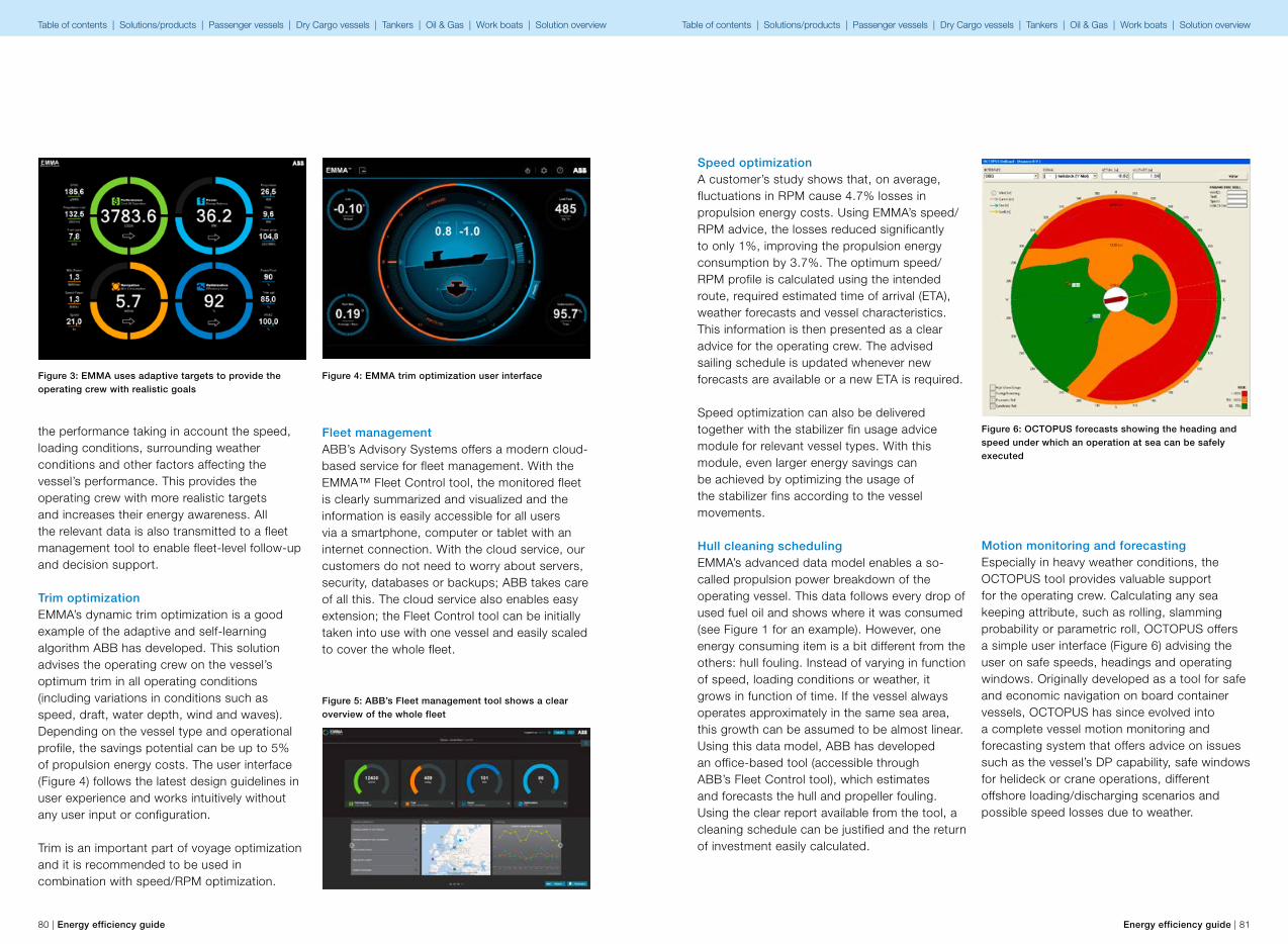
80 | Energy efficiency guide Energy efficiency guide | 81
the performance taking in account the speed, loading conditions, surrounding weather conditions and other factors affecting the vessel’s performance. This provides the operating crew with more realistic targets and increases their energy awareness. All the relevant data is also transmitted to a fleet management tool to enable fleet-level follow-up and decision support.
Trim optimizationEMMA’s dynamic trim optimization is a good example of the adaptive and self-learning algorithm ABB has developed. This solution advises the operating crew on the vessel’s optimum trim in all operating conditions (including variations in conditions such as speed, draft, water depth, wind and waves). Depending on the vessel type and operational profile, the savings potential can be up to 5% of propulsion energy costs. The user interface (Figure 4) follows the latest design guidelines in user experience and works intuitively without any user input or configuration.
Trim is an important part of voyage optimization and it is recommended to be used in combination with speed/RPM optimization.
Fleet managementABB’s Advisory Systems offers a modern cloud-based service for fleet management. With the EMMA™ Fleet Control tool, the monitored fleet is clearly summarized and visualized and the information is easily accessible for all users via a smartphone, computer or tablet with an internet connection. With the cloud service, our customers do not need to worry about servers, security, databases or backups; ABB takes care of all this. The cloud service also enables easy extension; the Fleet Control tool can be initially taken into use with one vessel and easily scaled to cover the whole fleet.
Figure 5: ABB’s Fleet management tool shows a clear overview of the whole fleet
Figure 3: EMMA uses adaptive targets to provide the operating crew with realistic goals
Figure 4: EMMA trim optimization user interface
Speed optimizationA customer’s study shows that, on average, fluctuations in RPM cause 4.7% losses in propulsion energy costs. Using EMMA’s speed/RPM advice, the losses reduced significantly to only 1%, improving the propulsion energy consumption by 3.7%. The optimum speed/RPM profile is calculated using the intended route, required estimated time of arrival (ETA), weather forecasts and vessel characteristics. This information is then presented as a clear advice for the operating crew. The advised sailing schedule is updated whenever new forecasts are available or a new ETA is required.
Speed optimization can also be delivered together with the stabilizer fin usage advice module for relevant vessel types. With this module, even larger energy savings can be achieved by optimizing the usage of the stabilizer fins according to the vessel movements.
Hull cleaning schedulingEMMA’s advanced data model enables a so-called propulsion power breakdown of the operating vessel. This data follows every drop of used fuel oil and shows where it was consumed (see Figure 1 for an example). However, one energy consuming item is a bit different from the others: hull fouling. Instead of varying in function of speed, loading conditions or weather, it grows in function of time. If the vessel always operates approximately in the same sea area, this growth can be assumed to be almost linear. Using this data model, ABB has developed an office-based tool (accessible through ABB’s Fleet Control tool), which estimates and forecasts the hull and propeller fouling. Using the clear report available from the tool, a cleaning schedule can be justified and the return of investment easily calculated.
Figure 6: OCTOPUS forecasts showing the heading and speed under which an operation at sea can be safely executed
Motion monitoring and forecastingEspecially in heavy weather conditions, the OCTOPUS tool provides valuable support for the operating crew. Calculating any sea keeping attribute, such as rolling, slamming probability or parametric roll, OCTOPUS offers a simple user interface (Figure 6) advising the user on safe speeds, headings and operating windows. Originally developed as a tool for safe and economic navigation on board container vessels, OCTOPUS has since evolved into a complete vessel motion monitoring and forecasting system that offers advice on issues such as the vessel’s DP capability, safe windows for helideck or crane operations, different offshore loading/discharging scenarios and possible speed losses due to weather.
Table of contents | Solutions/products | Passenger vessels | Dry Cargo vessels | Tankers | Oil & Gas | Work boats | Solution overview Table of contents | Solutions/products | Passenger vessels | Dry Cargo vessels | Tankers | Oil & Gas | Work boats | Solution overview
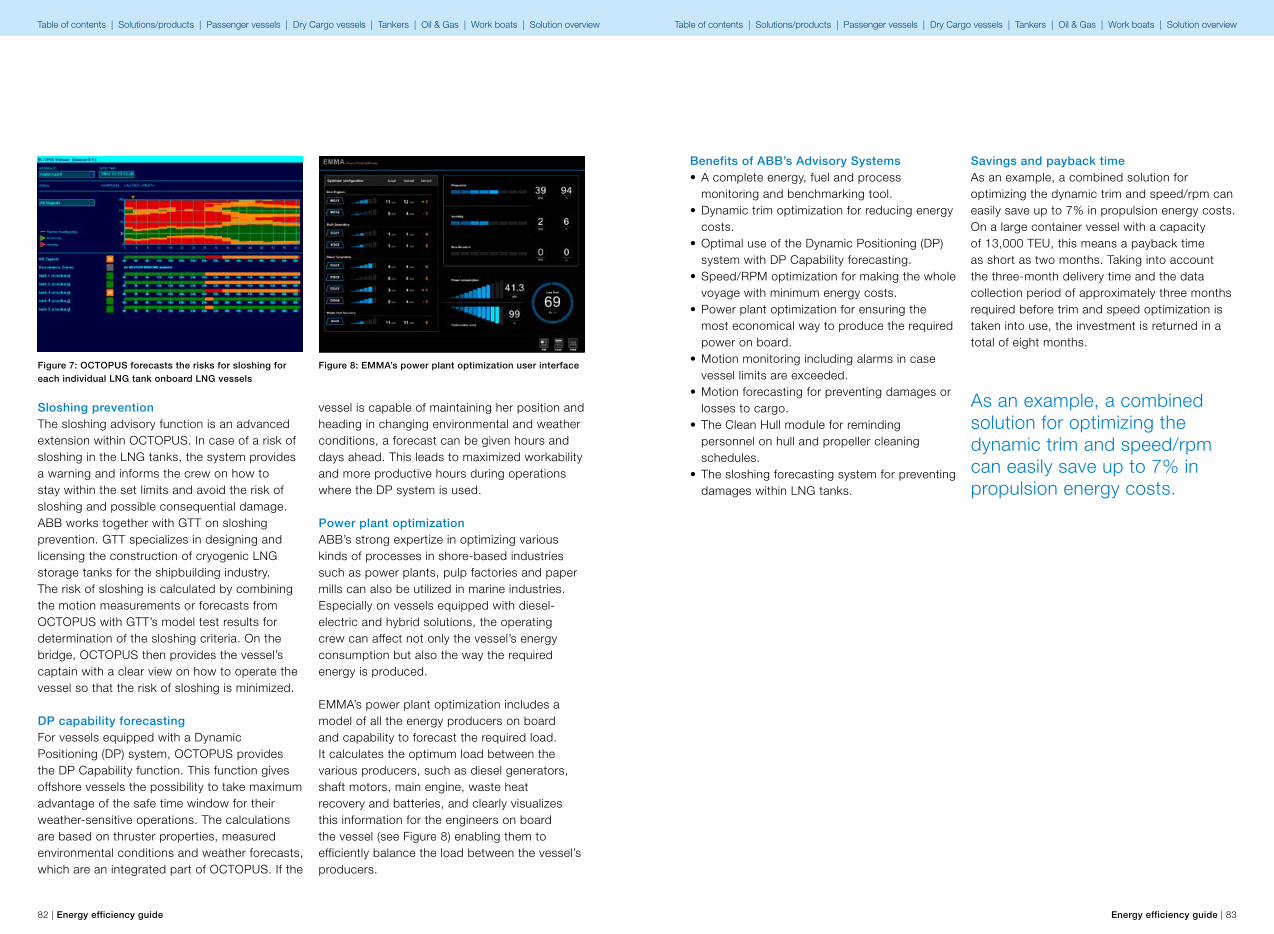
82 | Energy efficiency guide Energy efficiency guide | 83
Sloshing preventionThe sloshing advisory function is an advanced extension within OCTOPUS. In case of a risk of sloshing in the LNG tanks, the system provides a warning and informs the crew on how to stay within the set limits and avoid the risk of sloshing and possible consequential damage. ABB works together with GTT on sloshing prevention. GTT specializes in designing and licensing the construction of cryogenic LNG storage tanks for the shipbuilding industry. The risk of sloshing is calculated by combining the motion measurements or forecasts from OCTOPUS with GTT’s model test results for determination of the sloshing criteria. On the bridge, OCTOPUS then provides the vessel’s captain with a clear view on how to operate the vessel so that the risk of sloshing is minimized.
DP capability forecastingFor vessels equipped with a Dynamic Positioning (DP) system, OCTOPUS provides the DP Capability function. This function gives offshore vessels the possibility to take maximum advantage of the safe time window for their weather-sensitive operations. The calculations are based on thruster properties, measured environmental conditions and weather forecasts, which are an integrated part of OCTOPUS. If the
vessel is capable of maintaining her position and heading in changing environmental and weather conditions, a forecast can be given hours and days ahead. This leads to maximized workability and more productive hours during operations where the DP system is used.
Power plant optimizationABB’s strong expertize in optimizing various kinds of processes in shore-based industries such as power plants, pulp factories and paper mills can also be utilized in marine industries. Especially on vessels equipped with diesel-electric and hybrid solutions, the operating crew can affect not only the vessel’s energy consumption but also the way the required energy is produced.
EMMA’s power plant optimization includes a model of all the energy producers on board and capability to forecast the required load. It calculates the optimum load between the various producers, such as diesel generators, shaft motors, main engine, waste heat recovery and batteries, and clearly visualizes this information for the engineers on board the vessel (see Figure 8) enabling them to efficiently balance the load between the vessel’s producers.
Figure 8: EMMA’s power plant optimization user interfaceFigure 7: OCTOPUS forecasts the risks for sloshing for each individual LNG tank onboard LNG vessels
Benefits of ABB’s Advisory Systems• A complete energy, fuel and process
monitoring and benchmarking tool.• Dynamic trim optimization for reducing energy
costs.• Optimal use of the Dynamic Positioning (DP)
system with DP Capability forecasting.• Speed/RPM optimization for making the whole
voyage with minimum energy costs.• Power plant optimization for ensuring the
most economical way to produce the required power on board.
• Motion monitoring including alarms in case vessel limits are exceeded.
• Motion forecasting for preventing damages or losses to cargo.
• The Clean Hull module for reminding personnel on hull and propeller cleaning schedules.
• The sloshing forecasting system for preventing damages within LNG tanks.
As an example, a combined solution for optimizing the dynamic trim and speed/rpm can easily save up to 7% in propulsion energy costs.
Savings and payback timeAs an example, a combined solution for optimizing the dynamic trim and speed/rpm can easily save up to 7% in propulsion energy costs. On a large container vessel with a capacity of 13,000 TEU, this means a payback time as short as two months. Taking into account the three-month delivery time and the data collection period of approximately three months required before trim and speed optimization is taken into use, the investment is returned in a total of eight months.
Table of contents | Solutions/products | Passenger vessels | Dry Cargo vessels | Tankers | Oil & Gas | Work boats | Solution overview Table of contents | Solutions/products | Passenger vessels | Dry Cargo vessels | Tankers | Oil & Gas | Work boats | Solution overview
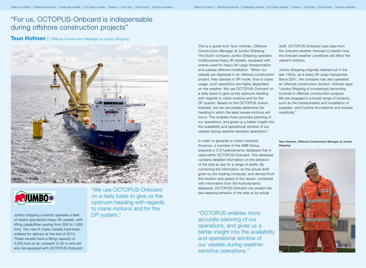
84 | Energy efficiency guide Energy efficiency guide | 85
“For us, OCTOPUS-Onboard is indispensable during offshore construction projects”
Jumbo shipping currently operates a fleet of twelve specialized heavy lift vessels, with lifting capabilities varying from 500 to 1,800 tons. Two new K-Class vessels have been ordered for delivery at the end of 2013. These vessels have a lifting capacity of 3,000 tons at an outreach of 20 m and will also be equipped with OCTOPUS-Onboard.
“We use OCTOPUS-Onboard on a daily basis to give us the optimum heading with regards to crane motions and for the DP system.”
Teun Hofman | Offshore Construction Manager at Jumbo Shipping
This is a quote from Teun Hofman, Offshore Construction Manager at Jumbo Shipping. The Dutch company Jumbo Shipping operates multipurpose heavy lift vessels, equipped with cranes used for heavy-lift cargo transportation and subsea offshore installation. “When our vessels are deployed in an offshore construction project, they operate in DP mode. Due to crane usage, such operations are highly dependent on the weather. We use OCTOPUS-Onboard on a daily basis to give us the optimum heading with regards to crane motions and for the DP system. Based on the OCTOPUS motion forecast, we can accurately determine the heading in which the least severe motions will occur. This enables more-accurate planning of our operations, and gives us a better insight into the availability and operational window of our vessels during weather-sensitive operations.”
In order to generate a motion forecast, Amarcon, a member of the ABB Group, prepares a 3-D hydrodynamic database that is used within OCTOPUS-Onboard. This database contains detailed information on the behavior of the ship at sea for a range of drafts. By combining the information on the actual draft given by the loading computer, and derived from the location and speed of the vessel, combined with information from the hydrodynamic database, OCTOPUS-Onboard can predict the sea-keeping behavior of the ship at its actual
Teun Hofman, Offshore Construction Manager at Jumbo Shipping
“OCTOPUS enables more-accurate planning of our operations, and gives us a better insight into the availability and operational window of our vessels during weather-sensitive operations.”
draft. OCTOPUS-Onboard uses data from the onboard weather forecast to predict how the forecast weather conditions will affect the vessel’s motions.
Jumbo Shipping originally started out in the late 1950s, as a heavy lift cargo transporter. Since 2001, the company has also operated an offshore construction division. Hofman says: “Jumbo Shipping is increasingly becoming involved in offshore construction projects. We are engaged in a broad range of projects, such as the transportation and installation of topsides, wind turbine foundations and subsea manifolds.”
Table of contents | Solutions/products | Passenger vessels | Dry Cargo vessels | Tankers | Oil & Gas | Work boats | Solution overview Table of contents | Solutions/products | Passenger vessels | Dry Cargo vessels | Tankers | Oil & Gas | Work boats | Solution overview

TT
PP
LTCOOLER
SW PUMPS3x50% VARIABLE
SPEEDDRIVES
8112/01 8112/02
8111
/01
8111
/02
8111
/03
SEACHEST
(low)
SEACHEST(high)
DIS
CH
AR
GE
LTCOOLER
86 | Energy efficiency guide Energy efficiency guide | 87
6.2. Variable frequency drive for cooling systems
Energy efficiency as part of the design criteriaUntil recently, energy efficiency in auxiliary systems was not considered during the design process or construction of marine vessels. For this reason, the systems on existing ships are not energy efficient and have not been fully optimized to minimize overall fuel consumption. Many of the ships currently in production continue to be built with little emphasis on energy efficient solutions. Additionally, shipyards typically do not focus on the long term cost of a vessel’s ownership. Unless the owners define the technologies to be included in the specifications, the ship’s energy efficiencies capabilities will be limited. To date, most marine installations adjust for changes in environmental conditions by inefficient methods, such as by using ‘throttling’ and ‘by-pass loops’.
The on board ship systems best suited to improving energy efficiency are systems with large pumps and fans, which are not required
to run continuously or at full capacity. Where applicable, electric motors could be fitted with VFD to operate pumps and fans more efficiently at partial loads, for example during slower sailing speeds or with reduced ventilation requirements. The electric power consumption of a pump is related to the pump volumetric flow according to affinity laws. The reduction of pump speed will affect the system pressure, Head, to the power of two and the electric power consumption to the power of three. For example, a reduction in pump speed of 10% will reduce power consumption by 27%.
Pumps and fans are vital parts of the processes on board a vesselPumps and fans on board vessels often perform vital functions. If these are not working, the vessel is not sailing.
On board vessels there are many different kinds of pump applications. Seawater cooling pumps, boiler feed pumps, HVAC pumps,
Figure 1: A typical seawater cooling system. Like most pump applications, these pumps are often greatly over-dimensioned to handle the most extreme operating conditions with good margin.
bilge water pumps, lubrications pumps, fire pumps, waste water pumps and many other kinds. It is common for pump applications to be over-dimensioned. This is simply because the design criterion is set to cope with the extreme conditions in which the vessel may operate. For example, the seawater temperature is generally dimensioned for above normal operating conditions.
Although it is necessary for a ship to be able to operate in extreme cases and environments, everyday operations rarely come close to such conditions. While the maximum allowed engine load is typically 75…90% of maximum, heat is always recovered from the system. Seawater temperature very seldom reaches the design value.
A lot of energy can easily be saved by controlling pumps and fans with a VFD, either standalone or with a pressure or temperature sensor loop control. Using a VFD to match the power demand to the operational conditions is the most effective method to optimize the on board systems.
Displacement pumps and centrifugal pumps are the two most common types of pump used on ships, but around 80% of all pumps on board ships are centrifugal pumps. This kind of pump has the same duty characteristics as a fan. Fans are used for ventilation in the engine room, on the car deck, in cargo spaces and in other places where forced ventilation is needed.
When operating a centrifugal pump or a fan you can achieve a fairly large reduction in energy consumption by making just a small reduction in rpm of the pump.
Cavitations are another important issue when considering pumps and their dimensioning. If the pump is too large, the suction capability will be weak, making the risk of cavitations very high.Cavitations appear as a result of evaporation of the fluid which occurs when the static pressure drops below the actual steam pressure inside the pump. Cavitations inside a pump can cause severe damage to the materials and, particularly, the impeller is often badly damaged. In some cases, damage to the impeller can cause the pump to fail within a couple of months. When using a VFD to decrease the pump speed you will also reduce the chance of cavitations, and the risk of damage to the pump.
By far the most commonly used flow control in pump applications is throttle control and by-pass loops to control the temperature. As a consequence pumps are running at 100% load continuously, even though the requirement would actually be about 40% on average. Using these antiquated control methods is as ineffective as controlling a car’s speed with the brakes while the engine is going at full throttle. In other words, not only does it waste energy but also accelerates equipment wear.
A reduction of the pump speed of 10% will save 27% of the consumed power.
Table of contents | Solutions/products | Passenger vessels | Dry Cargo vessels | Tankers | Oil & Gas | Work boats | Solution overview Table of contents | Solutions/products | Passenger vessels | Dry Cargo vessels | Tankers | Oil & Gas | Work boats | Solution overview

Recirculation
Throttling
Cyclic control
VFD
System curve
Savings potential
1000
Flow (%)20 40 60 80
10
20
30
40
50
60
70
80
90
100
Pow
er re
quire
d (%
)
88 | Energy efficiency guide Energy efficiency guide | 89
Reducing emissions doesn’t mean reengineering your existing vesselRetrofitting existing vessels with VFD is a task which demands knowledge of the process to be modified as well as good system knowledge of VFD, motors and pumps/fans. Sometimes it is necessary to replace the existing motor with a new motor designed for VFD use. This depends very much on the voltage level and power demand of the pump. Generally, ABB random wound motors with a voltage rating less than 500 V are good for VFD use as such, whilst other motor types should be checked case by case for suitability. ABB can provide expert insight on the cost / benefit trade-off of replacing motors. Market expansion of energy efficient motors has in effect reduced the price of these special motors.
The control method of the VFD depends on the existing automation system. In some cases it may be beneficial to install an independent control system for the modified processes.The ABB Marine Service can retrofit complete energy efficient design packages tailored to the customer’s requirements. These packages may include ABB’s products, project services and all site activities.
In vessels built between 1988 and 2008 and which are still sailing, approximately 2% of the main sea water cooling systems have VFD control. By modifying these systems, which is quite simple, substantial reductions in emissions and costs can be achieved. Small changes to the system can make a big impact on emission reduction.
Figure 2: The diagram shows the power consumption for different flow control methods. The grey area represents the energy savings generated by using a VFD instead of manual throttling.
Marine type approved driveABB’s variable frequency drive is type tested and approved for marine drive applications. The type approval test is required for essential applications on board. Essential applications are those which are related to navigation, propulsion, safety of the ship and passenger, cargo and crew. Examples of essential applications are ballast pumps, bilge pumps, circulating and cooling water pumps.
ABB’s variable frequency drive is type tested and approved by:• DNV (Det Norske Veritas) • LR (Lloyd’s Register of Shipping)• ABS (American Bureau of Shipping)• RINA (Registro Italiano Navale)• BV (Bureau Veritas)• GL (Germanischer Lloyd)
Intelligent pump control to further enhance the energy savings To further enhance the energy saving potential in pump and fan applications, ABB have introduced an Intelligent Pump Control solution (IPC). IPC is an optional software package for ABB low voltage variable frequency drives. Incorporating all of the most common functions required by pump or fan users, it eliminates the need for an external PLC and other additional components. A pump system with fewer electrical components will be more reliable, especially in the harsh environment typical of marine applications. IPC can help save energy, reduce downtime and prevent pump jamming and pipeline blocking.
Control logic of level control modeThe key issue is to run pumps with efficiency speed as far as possible. If the temperature demand in the cooling circuit varies so that more cooling water is needed, more pumps are switched on and they run at efficiency speed. In a situation where all pumps are running at efficiency speed and the cooling demand still increases, all pumps start to run at high speed.
With this method, according to the theory presented earlier, it is possible to achieve almost 20…30% more energy savings, and keep the cooling control flexible for highly varying cooling requirements.
Other benefits with intelligent pump controlDimensioning a cooling system with parallel pumps provides redundancy in the system. With the cooling demand control of the IPC solution, there is 100% redundancy in the system. If one of the pumps, motors, or drives switches off, the system will continue to operate uninterrupted. Even if the master parallel drive fails, it takes only 500 ms to activate the backup drive. This is made possible by a fast fiber optic connection between the drives. 100% redundancy in the system ensures continuous and risk-free operation of the pump system even in fault situations.
VFD mounted on a pump is by far the most efficient way to change the duty point of a pump system, and reduce the power consumption.
Table of contents | Solutions/products | Passenger vessels | Dry Cargo vessels | Tankers | Oil & Gas | Work boats | Solution overview Table of contents | Solutions/products | Passenger vessels | Dry Cargo vessels | Tankers | Oil & Gas | Work boats | Solution overview

90 | Energy efficiency guide Energy efficiency guide | 91
The anti-jam function enables the drive to perform preventive maintenance on the pump. When the function is triggered, the pump is run at high speed and then either reversed or stopped in a sequence of user-defined cleaning cycles. This helps to prevent congestion through the build-up of particles inside the pump. The trigger parameters (high current, run-on-time, external input and every start) are set by the user.
When operating with liquids containing particles there is always a risk that pipelines will get blocked – especially when running with smooth control and/or slow speeds. With Level Control fast mode fast ramp in starting creates a flush effect which keeps the pipelines clear. When the pumps are running, they are always operating at close to the nominal point where the risk of pipeline problems is reduced due to higher flow.
Pump priority control balances the operating time across all of the pumps in the system over a long time period. This facilitates maintenance planning and can boost energy efficiency by operating pumps at close to their best efficiency point. In a system where the consumption rate is higher during the sea voyage, for example, the drive can be programmed to operate higher capacity pumps during the sea voyage and smaller units at harbor time.
Pump and fan applications on board suitable for VFD
There is huge potential for retrofitting existing ships with new fuel-reducing technologies. For example, only around 2% of the global fleet is currently equipped with variable frequency drives for their seawater cooling pumps, which means that 98% of the fleet is missing an opportunity to reap high fuel savings and environmental rewards.
On board pump and fan applications suitable for VFD• Seawater pumps• High and low temperature cooling water
pumps• Boiler feed pumps• Bilge water pumps• Waste water pumps• Engine room ventilation fans• Cargo area fans• Air handling units, such as air conditioning
systems on board cruise ships and passenger vessels
• Hotel auxiliary system pumps and fans (mainly in passenger vessels)
Major benefits from installing a VFD• Soft starting – no high starting currents
causing disturbance on the network.• No process disturbance due to voltage drops;
no trips of other electrical devices connected to same bus.
• No excessive thermo-mechanical stress on the motor; longer lifetime of the motor.
• Immediate start-up without warming-up delays (e.g. steam turbines).
• Controlled and smooth start-up.• Accurate process control – flow based on
production need.• Mechanical wear of piping is minimized.• Risk of cavitations in the pump is minimized.• Passenger comfort (in air conditioning
application).• Reliability/technical improvement.• Environmental compliancy.• Lower energy bills.
Savings and payback timeABB’s VFD solution reduces a ship’s energy and fuel consumption, bringing savings in operational costs. Based on affinity laws, a linear reduction of pump or fan speed leads to a cubic reduction of electric power. Consequently, a 10% reduction of pump speed can save 27% of the energy cost related to the pump.
ABB’s VFD solution typically has a 6-18 months payback time.
Table of contents | Solutions/products | Passenger vessels | Dry Cargo vessels | Tankers | Oil & Gas | Work boats | Solution overview Table of contents | Solutions/products | Passenger vessels | Dry Cargo vessels | Tankers | Oil & Gas | Work boats | Solution overview
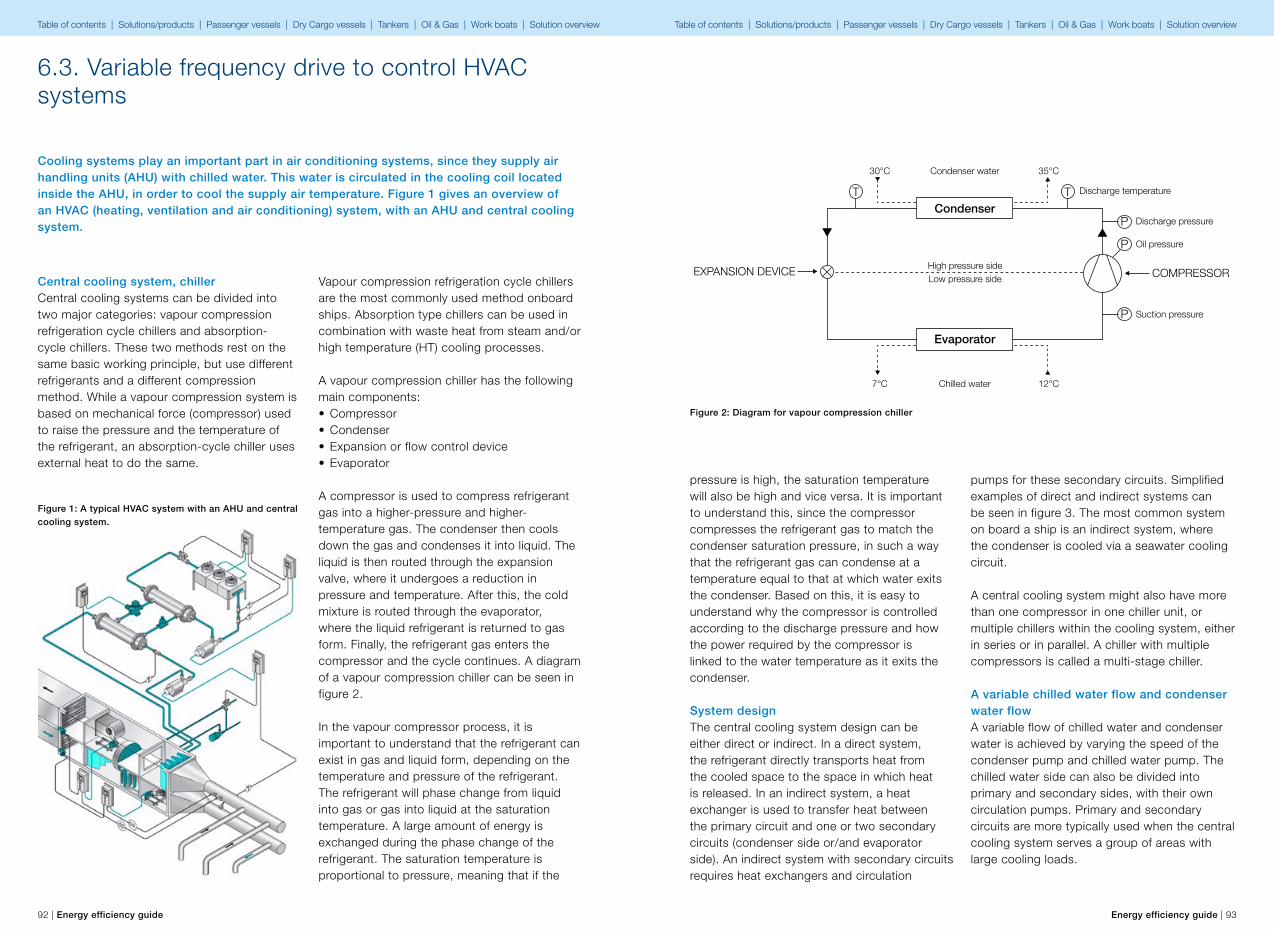
P
P
P
TT
EXPANSION DEVICE COMPRESSOR
Discharge pressure
Discharge temperature
Oil pressure
Suction pressure
Condenser water
Condenser
Evaporator
30°C 35°C
Chilled water
High pressure sideLow pressure side
7°C 12°C
92 | Energy efficiency guide Energy efficiency guide | 93
6.3. Variable frequency drive to control HVAC systems
Cooling systems play an important part in air conditioning systems, since they supply air handling units (AHU) with chilled water. This water is circulated in the cooling coil located inside the AHU, in order to cool the supply air temperature. Figure 1 gives an overview of an HVAC (heating, ventilation and air conditioning) system, with an AHU and central cooling system.
Vapour compression refrigeration cycle chillers are the most commonly used method onboard ships. Absorption type chillers can be used in combination with waste heat from steam and/or high temperature (HT) cooling processes.
A vapour compression chiller has the following main components:• Compressor• Condenser• Expansion or flow control device• Evaporator
A compressor is used to compress refrigerant gas into a higher-pressure and higher-temperature gas. The condenser then cools down the gas and condenses it into liquid. The liquid is then routed through the expansion valve, where it undergoes a reduction in pressure and temperature. After this, the cold mixture is routed through the evaporator, where the liquid refrigerant is returned to gas form. Finally, the refrigerant gas enters the compressor and the cycle continues. A diagram of a vapour compression chiller can be seen in figure 2.
In the vapour compressor process, it is important to understand that the refrigerant can exist in gas and liquid form, depending on the temperature and pressure of the refrigerant. The refrigerant will phase change from liquid into gas or gas into liquid at the saturation temperature. A large amount of energy is exchanged during the phase change of the refrigerant. The saturation temperature is proportional to pressure, meaning that if the
Figure 1: A typical HVAC system with an AHU and central cooling system.
Central cooling system, chillerCentral cooling systems can be divided into two major categories: vapour compression refrigeration cycle chillers and absorption-cycle chillers. These two methods rest on the same basic working principle, but use different refrigerants and a different compression method. While a vapour compression system is based on mechanical force (compressor) used to raise the pressure and the temperature of the refrigerant, an absorption-cycle chiller uses external heat to do the same.
pressure is high, the saturation temperature will also be high and vice versa. It is important to understand this, since the compressor compresses the refrigerant gas to match the condenser saturation pressure, in such a way that the refrigerant gas can condense at a temperature equal to that at which water exits the condenser. Based on this, it is easy to understand why the compressor is controlled according to the discharge pressure and how the power required by the compressor is linked to the water temperature as it exits the condenser.
System designThe central cooling system design can be either direct or indirect. In a direct system, the refrigerant directly transports heat from the cooled space to the space in which heat is released. In an indirect system, a heat exchanger is used to transfer heat between the primary circuit and one or two secondary circuits (condenser side or/and evaporator side). An indirect system with secondary circuits requires heat exchangers and circulation
pumps for these secondary circuits. Simplified examples of direct and indirect systems can be seen in figure 3. The most common system on board a ship is an indirect system, where the condenser is cooled via a seawater cooling circuit.
A central cooling system might also have more than one compressor in one chiller unit, or multiple chillers within the cooling system, either in series or in parallel. A chiller with multiple compressors is called a multi-stage chiller.
A variable chilled water flow and condenser water flowA variable flow of chilled water and condenser water is achieved by varying the speed of the condenser pump and chilled water pump. The chilled water side can also be divided into primary and secondary sides, with their own circulation pumps. Primary and secondary circuits are more typically used when the central cooling system serves a group of areas with large cooling loads.
Figure 2: Diagram for vapour compression chiller
Table of contents | Solutions/products | Passenger vessels | Dry Cargo vessels | Tankers | Oil & Gas | Work boats | Solution overview Table of contents | Solutions/products | Passenger vessels | Dry Cargo vessels | Tankers | Oil & Gas | Work boats | Solution overview

Condenser water pump
Chilled water pump
Evaporator
Evaporator
Condenser
Heat exchanger
Heat exchanger
Condenser
Q1
Q2
n1
n2
n1
n2
P1
P2
3= =and ( )
100
80
60
40
20
00 20 40Speed (%RPM), Flow (%GPM or %CFM)
60 80 100
Pow
er (%
HP
) (%
kW) P1
P2
= ( )N1
N2
3
94 | Energy efficiency guide Energy efficiency guide | 95
Consideration should be given to a variable flow on the chilled water side in cases where the cooling load varies significantly. Differential pressure measurement is used to control the chilled water pumps, in order to secure an adequate water flow, even at the system’s remotest cooling coil.
Consideration could be given to using variable frequency drives (VFD) on the chilled water side, in both variable flow and constant pressure systems.
More often than not, a constant pressure system is over dimensioned for the need in hand, considering the fouling margins, and the pressure in the system is kept stable using manually controlled valves. Applying a VFD with fully opened valves, based on using the VFD to control pressure, is viewed as more energy efficient.
Savings in chilled water pumps are based on controlling the flow of the system, by using balancing valves, rather than a throttling system, to control the speed of the pump. The actual
power requirement of the circulation pumps is calculated based on the flow rate and pressure over the pump, according to the following formula:
P = q x dP
Where q is the volume flow rate of the pump and dP is the pressure difference over the pump.
The given pump power is theoretical and takes no account of efficiencies. On the other hand, no account is taken of the fouling margins of the piping design either, due to which using theoretical power as the base for the saving estimation is viewed as justified.
Energy savings of up to 30% can be achieved by using VFD to control the pumps, rather than controlling the process with balancing valves.
Onboard a ship, the chiller, particularly the condenser side, is dimensioned based on the
Figure 3: Direct system on the left and indirect system on the right
ship’s operating profile. For example, on a cruise ship cruising on the Caribbean, the condenser side must be dimensioned to a relatively high seawater temperature, typically 32 – 35°C. When the same ship cruises on European waters or in a colder climate, the temperature at which the water enters the system is lower than the dimensioned temperature, leaving room for variable flow in the seawater entering the condenser.
Applying a VFD to the seawater cooling pump, which ensures that the seawater flow rate is kept above the minimum flow rate approved by the chiller manufacturer (to avoid laminar flow and scaling), can reduce the flow by as much as 40%.
In a piping system where the flow is controlled by controlling the speed of the pump, the flow rate and the power requirement of the pump follow affinity laws, as described below:
Where Q is the flow rate of the system, n is the running speed of the pump and P is the pump’s power requirement.
The affinity laws state that the power requirement increases by the velocity cubed, meaning that while even a small increase in speed requires much more power, a modest speed reduction can yield significant energy savings. Figure 4 illustrates how a pump or fan running at half speed consumes only one-eighth of the power of one running at full speed – by reducing the motor speed by 20 per cent, the required power can be lowered by up to 50 per cent.
Compressor typesMany types of compressors are available, with a range of characteristics. Compressors are typically divided, based on the compression mechanism used, into two broad categories: positive displacement and dynamic compressors. While both of these categories include several styles of compressor, the most commonly used ones in HVAC are shown in figure 5.
Positive displacement compressors physically compress the vaporised refrigerant into higher pressures and smaller volumes, by reducing the volume of the compression chamber, while dynamic compressors increase vaporised refrigerant pressure, by the continuous transfer of kinetic energy to the refrigerant, using a rotating impeller.
Positive displacement compressors are relatively constant torque applications, while dynamic compressors are varying torque applications.
Figure 4: A pump or fan running at half speed consumes only one-eighth of the power
Table of contents | Solutions/products | Passenger vessels | Dry Cargo vessels | Tankers | Oil & Gas | Work boats | Solution overview Table of contents | Solutions/products | Passenger vessels | Dry Cargo vessels | Tankers | Oil & Gas | Work boats | Solution overview
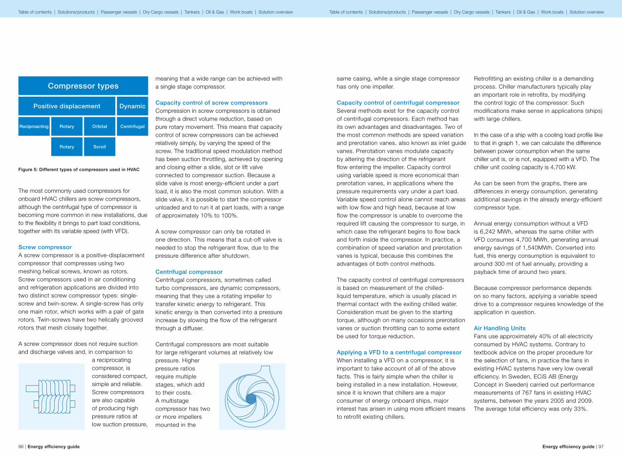
96 | Energy efficiency guide Energy efficiency guide | 97
The most commonly used compressors for onboard HVAC chillers are screw compressors, although the centrifugal type of compressor is becoming more common in new installations, due to the flexibility it brings to part load conditions, together with its variable speed (with VFD).
Screw compressorA screw compressor is a positive-displacement compressor that compresses using two meshing helical screws, known as rotors. Screw compressors used in air conditioning and refrigeration applications are divided into two distinct screw compressor types: single-screw and twin-screw. A single-screw has only one main rotor, which works with a pair of gate rotors. Twin-screws have two helically grooved rotors that mesh closely together.
A screw compressor does not require suction and discharge valves and, in comparison to
a reciprocating compressor, is considered compact, simple and reliable. Screw compressors are also capable of producing high pressure ratios at low suction pressure,
meaning that a wide range can be achieved with a single stage compressor.
Capacity control of screw compressorsCompression in screw compressors is obtained through a direct volume reduction, based on pure rotary movement. This means that capacity control of screw compressors can be achieved relatively simply, by varying the speed of the screw. The traditional speed modulation method has been suction throttling, achieved by opening and closing either a slide, slot or lift valve connected to compressor suction. Because a slide valve is most energy-efficient under a part load, it is also the most common solution. With a slide valve, it is possible to start the compressor unloaded and to run it at part loads, with a range of approximately 10% to 100%.
A screw compressor can only be rotated in one direction. This means that a cut-off valve is needed to stop the refrigerant flow, due to the pressure difference after shutdown.
Centrifugal compressorCentrifugal compressors, sometimes called turbo compressors, are dynamic compressors, meaning that they use a rotating impeller to transfer kinetic energy to refrigerant. This kinetic energy is then converted into a pressure increase by slowing the flow of the refrigerant through a diffuser.
Centrifugal compressors are most suitable for large refrigerant volumes at relatively low pressure. Higher pressure ratios require multiple stages, which add to their costs. A multistage compressor has two or more impellers mounted in the
Figure 5: Different types of compressors used in HVAC
Compressor types
Positive displacement Dynamic
CentrifugalReciproacting Rotary
Rotary
Orbital
Scroll
same casing, while a single stage compressor has only one impeller.
Capacity control of centrifugal compressorSeveral methods exist for the capacity control of centrifugal compressors. Each method has its own advantages and disadvantages. Two of the most common methods are speed variation and prerotation vanes, also known as inlet guide vanes. Prerotation vanes modulate capacity by altering the direction of the refrigerant flow entering the impeller. Capacity control using variable speed is more economical than prerotation vanes, in applications where the pressure requirements vary under a part load. Variable speed control alone cannot reach areas with low flow and high head, because at low flow the compressor is unable to overcome the required lift causing the compressor to surge, in which case the refrigerant begins to flow back and forth inside the compressor. In practice, a combination of speed variation and prerotation vanes is typical, because this combines the advantages of both control methods.
The capacity control of centrifugal compressors is based on measurement of the chilled-liquid temperature, which is usually placed in thermal contact with the exiting chilled water. Consideration must be given to the starting torque, although on many occasions prerotation vanes or suction throttling can to some extent be used for torque reduction.
Applying a VFD to a centrifugal compressorWhen installing a VFD on a compressor, it is important to take account of all of the above facts. This is fairly simple when the chiller is being installed in a new installation. However, since it is known that chillers are a major consumer of energy onboard ships, major interest has arisen in using more efficient means to retrofit existing chillers.
Retrofitting an existing chiller is a demanding process. Chiller manufacturers typically play an important role in retrofits, by modifying the control logic of the compressor. Such modifications make sense in applications (ships) with large chillers. In the case of a ship with a cooling load profile like to that in graph 1, we can calculate the difference between power consumption when the same chiller unit is, or is not, equipped with a VFD. The chiller unit cooling capacity is 4,700 kW.
As can be seen from the graphs, there are differences in energy consumption, generating additional savings in the already energy-efficient compressor type.
Annual energy consumption without a VFD is 6,242 MWh, whereas the same chiller with VFD consumes 4,700 MWh, generating annual energy savings of 1,540MWh. Converted into fuel, this energy consumption is equivalent to around 300 mt of fuel annually, providing a payback time of around two years.
Because compressor performance depends on so many factors, applying a variable speed drive to a compressor requires knowledge of the application in question.
Air Handling UnitsFans use approximately 40% of all electricity consumed by HVAC systems. Contrary to textbook advice on the proper procedure for the selection of fans, in practice the fans in existing HVAC systems have very low overall efficiency. In Sweden, ECiS AB (Energy Concept in Sweden) carried out performance measurements of 767 fans in existing HVAC systems, between the years 2005 and 2009. The average total efficiency was only 33%.
Table of contents | Solutions/products | Passenger vessels | Dry Cargo vessels | Tankers | Oil & Gas | Work boats | Solution overview Table of contents | Solutions/products | Passenger vessels | Dry Cargo vessels | Tankers | Oil & Gas | Work boats | Solution overview
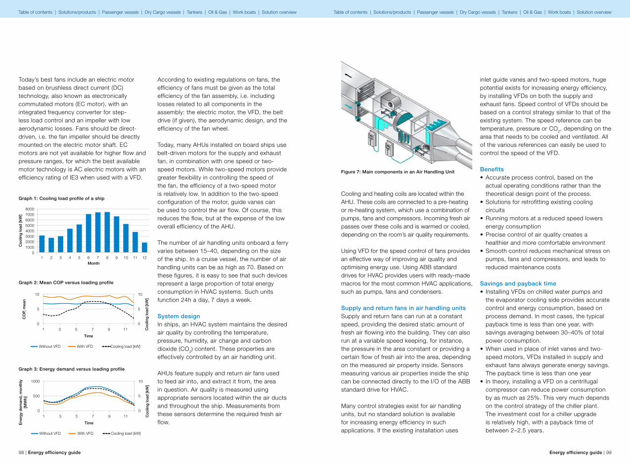
1
80007000600050004000300020001000
02 3 4 5
Month
Co
olin
g lo
ad [k
W]
6 7 8 9 10 11 12
1
1000
500
0
10
5
03 5
Time
Without VFD With VFD Cooling load [kW]
Co
olin
g lo
ad [k
W]
Ene
rgy
dem
and
, mo
nthl
y[M
Wh]
7 9 11
1
10
5
0
10
5
03 5
Time
Without VFD With VFD Cooling load [kW]
Co
olin
g lo
ad [k
W]
CO
P, m
ean
7 9 11
98 | Energy efficiency guide Energy efficiency guide | 99
Today’s best fans include an electric motor based on brushless direct current (DC) technology, also known as electronically commutated motors (EC motor), with an integrated frequency converter for step-less load control and an impeller with low aerodynamic losses. Fans should be direct-driven, i.e. the fan impeller should be directly mounted on the electric motor shaft. EC motors are not yet available for higher flow and pressure ranges, for which the best available motor technology is AC electric motors with an efficiency rating of IE3 when used with a VFD.
According to existing regulations on fans, the efficiency of fans must be given as the total efficiency of the fan assembly, i.e. including losses related to all components in the assembly: the electric motor, the VFD, the belt drive (if given), the aerodynamic design, and the efficiency of the fan wheel.
Today, many AHUs installed on board ships use belt-driven motors for the supply and exhaust fan, in combination with one speed or two-speed motors. While two-speed motors provide greater flexibility in controlling the speed of the fan, the efficiency of a two-speed motor is relatively low. In addition to the two-speed configuration of the motor, guide vanes can be used to control the air flow. Of course, this reduces the flow, but at the expense of the low overall efficiency of the AHU.
The number of air handling units onboard a ferry varies between 15–40, depending on the size of the ship. In a cruise vessel, the number of air handling units can be as high as 70. Based on these figures, it is easy to see that such devices represent a large proportion of total energy consumption in HVAC systems. Such units function 24h a day, 7 days a week.
System designIn ships, an HVAC system maintains the desired air quality by controlling the temperature, pressure, humidity, air change and carbon dioxide (CO2) content. These properties are effectively controlled by an air handling unit.
AHUs feature supply and return air fans used to feed air into, and extract it from, the area in question. Air quality is measured using appropriate sensors located within the air ducts and throughout the ship. Measurements from these sensors determine the required fresh air flow.
Graph 1: Cooling load profile of a ship
Graph 2: Mean COP versus loading profile
Graph 3: Energy demand versus loading profile
Cooling and heating coils are located within the AHU. These coils are connected to a pre-heating or re-heating system, which use a combination of pumps, fans and compressors. Incoming fresh air passes over these coils and is warmed or cooled, depending on the room’s air quality requirements.
Using VFD for the speed control of fans provides an effective way of improving air quality and optimising energy use. Using ABB standard drives for HVAC provides users with ready-made macros for the most common HVAC applications, such as pumps, fans and condensers.
Supply and return fans in air handling unitsSupply and return fans can run at a constant speed, providing the desired static amount of fresh air flowing into the building. They can also run at a variable speed keeping, for instance, the pressure in the area constant or providing a certain flow of fresh air into the area, depending on the measured air property inside. Sensors measuring various air properties inside the ship can be connected directly to the I/O of the ABB standard drive for HVAC.
Many control strategies exist for air handling units, but no standard solution is available for increasing energy efficiency in such applications. If the existing installation uses
inlet guide vanes and two-speed motors, huge potential exists for increasing energy efficiency, by installing VFDs on both the supply and exhaust fans. Speed control of VFDs should be based on a control strategy similar to that of the existing system. The speed reference can be temperature, pressure or CO2, depending on the area that needs to be cooled and ventilated. All of the various references can easily be used to control the speed of the VFD.
Benefits• Accurate process control, based on the
actual operating conditions rather than the theoretical design point of the process.
• Solutions for retrofitting existing cooling circuits
• Running motors at a reduced speed lowers energy consumption
• Precise control of air quality creates a healthier and more comfortable environment
• Smooth control reduces mechanical stress on pumps, fans and compressors, and leads to reduced maintenance costs
Savings and payback time• Installing VFDs on chilled water pumps and
the evaporator cooling side provides accurate control and energy consumption, based on process demand. In most cases, the typical payback time is less than one year, with savings averaging between 30–40% of total power consumption.
• When used in place of inlet vanes and two-speed motors, VFDs installed in supply and exhaust fans always generate energy savings. The payback time is less than one year
• In theory, installing a VFD on a centrifugal compressor can reduce power consumption by as much as 25%. This very much depends on the control strategy of the chiller plant. The investment cost for a chiller upgrade is relatively high, with a payback time of between 2–2.5 years.
Figure 7: Main components in an Air Handling Unit
Table of contents | Solutions/products | Passenger vessels | Dry Cargo vessels | Tankers | Oil & Gas | Work boats | Solution overview Table of contents | Solutions/products | Passenger vessels | Dry Cargo vessels | Tankers | Oil & Gas | Work boats | Solution overview
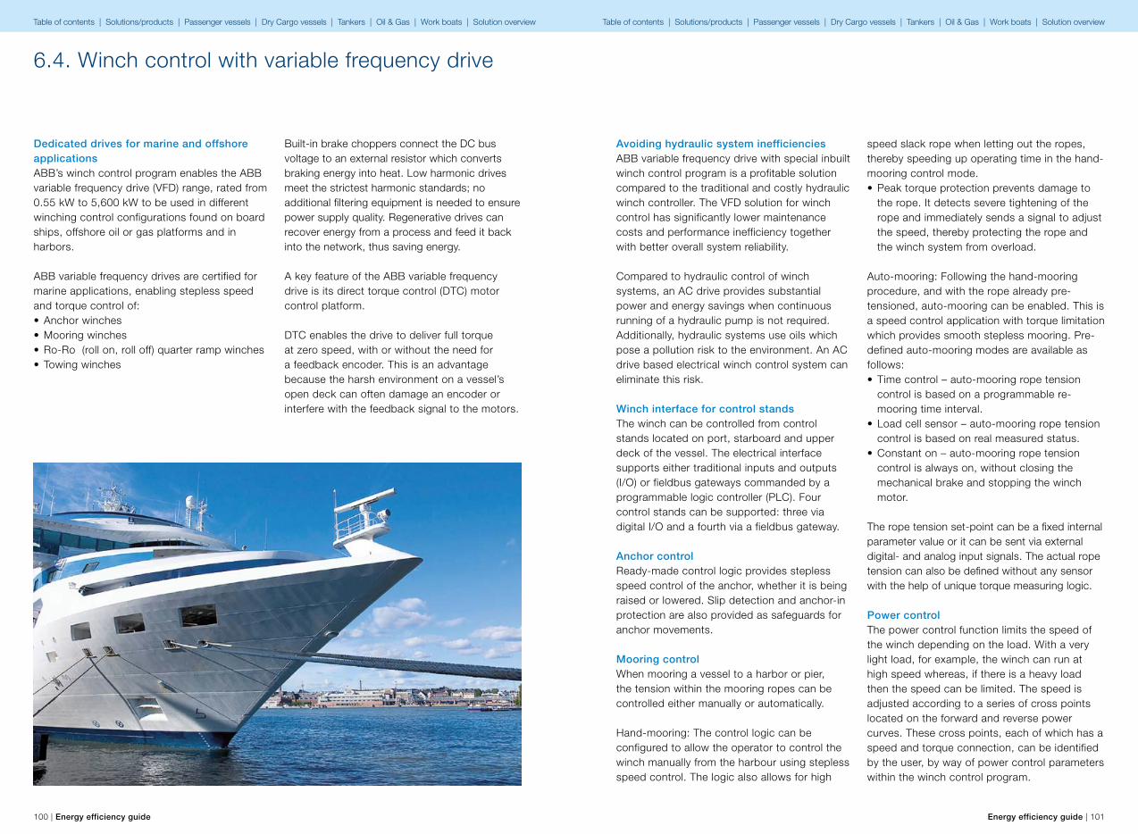
100 | Energy efficiency guide Energy efficiency guide | 101
6.4. Winch control with variable frequency drive
Dedicated drives for marine and offshore applicationsABB’s winch control program enables the ABB variable frequency drive (VFD) range, rated from 0.55 kW to 5,600 kW to be used in different winching control configurations found on board ships, offshore oil or gas platforms and in harbors.
ABB variable frequency drives are certified for marine applications, enabling stepless speed and torque control of:• Anchor winches• Mooring winches• Ro-Ro (roll on, roll off) quarter ramp winches• Towing winches
Built-in brake choppers connect the DC bus voltage to an external resistor which converts braking energy into heat. Low harmonic drives meet the strictest harmonic standards; no additional filtering equipment is needed to ensure power supply quality. Regenerative drives can recover energy from a process and feed it back into the network, thus saving energy.
A key feature of the ABB variable frequency drive is its direct torque control (DTC) motor control platform.
DTC enables the drive to deliver full torque at zero speed, with or without the need for a feedback encoder. This is an advantage because the harsh environment on a vessel’s open deck can often damage an encoder or interfere with the feedback signal to the motors.
Avoiding hydraulic system inefficienciesABB variable frequency drive with special inbuilt winch control program is a profitable solution compared to the traditional and costly hydraulic winch controller. The VFD solution for winch control has significantly lower maintenance costs and performance inefficiency together with better overall system reliability.
Compared to hydraulic control of winch systems, an AC drive provides substantial power and energy savings when continuous running of a hydraulic pump is not required. Additionally, hydraulic systems use oils which pose a pollution risk to the environment. An AC drive based electrical winch control system can eliminate this risk.
Winch interface for control standsThe winch can be controlled from control stands located on port, starboard and upper deck of the vessel. The electrical interface supports either traditional inputs and outputs (I/O) or fieldbus gateways commanded by a programmable logic controller (PLC). Four control stands can be supported: three via digital I/O and a fourth via a fieldbus gateway.
Anchor controlReady-made control logic provides stepless speed control of the anchor, whether it is being raised or lowered. Slip detection and anchor-in protection are also provided as safeguards for anchor movements.
Mooring controlWhen mooring a vessel to a harbor or pier, the tension within the mooring ropes can be controlled either manually or automatically.
Hand-mooring: The control logic can be configured to allow the operator to control the winch manually from the harbour using stepless speed control. The logic also allows for high
speed slack rope when letting out the ropes, thereby speeding up operating time in the hand-mooring control mode.• Peak torque protection prevents damage to
the rope. It detects severe tightening of the rope and immediately sends a signal to adjust the speed, thereby protecting the rope and the winch system from overload.
Auto-mooring: Following the hand-mooring procedure, and with the rope already pre-tensioned, auto-mooring can be enabled. This is a speed control application with torque limitation which provides smooth stepless mooring. Pre-defined auto-mooring modes are available as follows:• Time control – auto-mooring rope tension
control is based on a programmable re-mooring time interval.
• Load cell sensor – auto-mooring rope tension control is based on real measured status.
• Constant on – auto-mooring rope tension control is always on, without closing the mechanical brake and stopping the winch motor.
The rope tension set-point can be a fixed internal parameter value or it can be sent via external digital- and analog input signals. The actual rope tension can also be defined without any sensor with the help of unique torque measuring logic.
Power controlThe power control function limits the speed of the winch depending on the load. With a very light load, for example, the winch can run at high speed whereas, if there is a heavy load then the speed can be limited. The speed is adjusted according to a series of cross points located on the forward and reverse power curves. These cross points, each of which has a speed and torque connection, can be identified by the user, by way of power control parameters within the winch control program.
Table of contents | Solutions/products | Passenger vessels | Dry Cargo vessels | Tankers | Oil & Gas | Work boats | Solution overview Table of contents | Solutions/products | Passenger vessels | Dry Cargo vessels | Tankers | Oil & Gas | Work boats | Solution overview
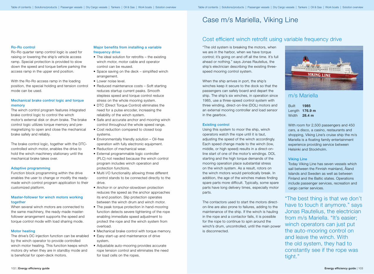
102 | Energy efficiency guide Energy efficiency guide | 103
Ro-Ro controlRo-Ro quarter ramp control logic is used for raising or lowering the ship’s vehicle access ramp. Special protection is provided to slow down the speed and torque before parking the access ramp in the upper end position.
With the Ro-Ro access ramp in the loading position, the special holding and tension control mode can be used.
Mechanical brake control logic and torque memoryThe winch control program features integrated brake control logic to control the winch motor’s external disk or drum brake. The brake control logic utilizes torque memory and pre-magnetizing to open and close the mechanical brake safely and reliably.
The brake control logic, together with the DTC-controlled winch motor, enables the drive to hold the winch machinery stationary until the mechanical brake takes over.
Adaptive programmingFunction block programming within the drive enables the user to change or modify the ready-made winch control program application to their customized platform.
Master-follower for winch motors working togetherWhen several winch motors are connected to the same machinery, the ready-made master-follower arrangement supports the speed and torque control mode with load sharing mode.
Motor heatingThe drive’s DC injection function can be enabled by the winch operator to provide controlled winch motor heating. This function keeps winch motors dry when they are in standby mode and is beneficial for open-deck motors.
Major benefits from installing a variable frequency drive• The ideal solution for retrofits – the existing
winch motor, motor cable and operator control can be reused.
• Space saving on the deck – simplified winch arrangement.
• Lower noise level.• Reduced maintenance costs – Soft starting
reduces startup current peaks. Smooth stepless speed and torque control reduce stress on the whole mooring system.
• DTC (Direct Torque Control) eliminates the need for a pulse encoder, increasing the reliability of the winch system.
• Safe and accurate anchor and mooring winch control throughout the whole speed range.
• Cost reduction compared to closed loop systems.
• Environmentally friendly solution – Oil-free operation with fully electronic equipment.
• Reduction of mechanical wear.• External programmable logic controller
(PLC) not needed because the winch control program includes winch operation and protection functions.
• Multi I/O functionality allowing three different control stands to be connected directly to the drive.
• Anchor-in or anchor-slowdown protection reduces the speed as the anchor approaches its end position. Slip protection operates between the winch drum and winch motor.
• The peak torque protection in hand-mooring function detects severe tightening of the rope enabling immediate speed adjustment to protect the rope and the winch system from overload.
• Mechanical brake control with torque memory.• Easy start-up and maintenance of drive
system.• Adjustable auto-mooring provides accurate
rope tension control and eliminates the need for load cells on the ropes.
Case m/s Mariella, Viking Line
Cost efficient winch retrofit using variable frequency drive“The old system is breaking the motors, when we are in the harbor, when we have torque control; it’s going on and off all the time. It’s full ahead or nothing.” says Jonas Rautelius, the ship’s electrician describing the existing three-speed mooring control system.
When the ship arrives in port, the ship’s winches keep it secure to the dock so that the passengers can safely board and depart the ship. The ship’s six winches, in operation since 1985, use a three-speed control system with three winding, direct-on-line (DOL) motors and an external mooring controller and load sensor in the gearbox.
Existing controlUsing this system to moor the ship, winch operators watch the rope until it is taut, adjusting the speed of the winch accordingly. Each speed change made to the winch (low, middle, or high speed) results in a direct-on-line start of one of the motor’s windings. DOL starting and the high torque demands of the mooring operation place substantial stress on the winch system. As a result, rotors on the winch motors would periodically break. In addition, the age of the winches makes finding spare parts more difficult. Typically, some spare parts have long delivery times, especially motor parts.
The contactors used to start the motors direct-on-line are also prone to failures, adding to the maintenance of the ship. If the winch is hauling in the rope and a contactor fails, it is possible for the rope to continue to spin around the winch’s drum, uncontrolled, until the main power is disconnected.
m/s Mariella
Built 1985Length 176.9 mWidth 28.4 m
With room for 2,500 passengers and 450 cars, a disco, a casino, restaurants and shopping, Viking Line’s cruise ship the m/s Mariella is a floating family entertainment experience providing service between Helsinki and Stockholm.
Viking LineToday Viking Line has seven vessels which sail between the Finnish mainland, Åland Islands and Sweden as well as between Finland and the Baltic states. Operations include passenger services, recreation and cargo carrier services.
“The best thing is that we don’t have to touch it anymore.” says Jonas Rautelius, the electrician from m/s Mariella. “It’s easier; winch operators can just put the auto-mooring control on and leave the winch. With the old system, they had to constantly see if the rope was tight.”
Table of contents | Solutions/products | Passenger vessels | Dry Cargo vessels | Tankers | Oil & Gas | Work boats | Solution overview Table of contents | Solutions/products | Passenger vessels | Dry Cargo vessels | Tankers | Oil & Gas | Work boats | Solution overview

104 | Energy efficiency guide Energy efficiency guide | 105
Cost efficient modernization with ABB drivesAfter contacting ABB, Viking Line decided to evaluate and test ABB’s proposed solution on one winch. Using the ship’s drawings from 1985, ABB specified the ACS800-01 marine certified industrial drive with the built-in winch control program. This allowed the m/s Mariella to keep the existing three-winding motor, motor cable, and operator control stands. “It was quite cheap to do it like this” says Jonas. “This is a big factor in deciding to do the rest.” The drive’s IP55 enclosure permitted it to be mounted directly to the wall of the ship.
Measuring torque allows auto-mooring without load cell sensorsBecause the drive uses ABB’s direct torque control (DTC), it does not rely on external sensors such as a load cell sensor in the gearbox or encoder on the motor. DTC allows open-loop control of the winch motor and this permitted the m/s Mariella to reuse the existing winch motor without having to install an encoder. The winch control program in the drive uses DTC and patented winch application torque measuring logic to measure the rope’s tension and to calculate the required torque at every start without a load cell sensor.
Figure 1: The existing winch motor, motor cable, mechani-cal disc brake and operator control stand were reused.
Figure 2: Rope tension is maintained automatically using time control sequences without a load cell sensor
Figure 3: Built-in auto-mooring with mechanical brake control keep the ship securely docked
Figure 4: The wall mounted ACS800 industrial drive with built-in winch control program replaced contactors for smooth, trouble free starting.
Case m/s Mariella, Viking Line – cost efficient winch retrofit using variable frequency drive
Easier operationWith the ABB solution, as the ship arrives in harbor, the winch operation starts with the drive in hand-mooring control to quickly and smoothly let out the rope at a high speed. When the rope is connected to the harbor, the winch hauls in the slack rope quickly. The winch control program’s peak torque protection function automatically stops the hand-mooring operation when the torque limits are reached. Winch operators then switch to auto-mooring mode. In auto-mooring mode, time control sequences are used to continually monitor the rope’s tension, automatically making adjustments as needed to keep the ship secure.“The best thing is that we don’t have to touch it anymore.” says Jonas. “It’s easier; winch operators can just put the auto-mooring control on and leave the winch. With the old system, they had to constantly see if the rope was tight.”
Integrated mechanical brake controlBrake control is integrated into the winch’s brake circuit through a relay output on the drive. The drive ensures the disc brake is closed before stopping the drive’s torque control. When opening the brake, the sequence is reversed, the drive determines and brings the motor to the needed torque to hold the rope’s tension, and then releases the brake.
Cost efficient retrofit• Improves reliability• Reduces maintenance• Reuses existing winch motor• Reuses existing motor cable• Reuses existing operator control stand• Replaces contactor control• Eliminates external load cell sensor• Eliminates auto-mooring unit• Integrated brake control• Soft starting eliminates start-up peaks• Smooth stepless speed and torque control• Improves operator experience• Marine certified hardware (ACS800-01)• Wall mounted drive• Adaptive programming in the drive is used to
match existing signals to drive controls
Case m/s Mariella, Viking Line – cost efficient winch retrofit using variable frequency drive
Significant savings with variable frequency drive.
Electrical winches offer significant savings over the conventional hydraulic winch configuration, as well as significant benefits in environmental issues. The vessel’s crew also benefits from considerably reduced noise levels on deck.
Table of contents | Solutions/products | Passenger vessels | Dry Cargo vessels | Tankers | Oil & Gas | Work boats | Solution overview Table of contents | Solutions/products | Passenger vessels | Dry Cargo vessels | Tankers | Oil & Gas | Work boats | Solution overview
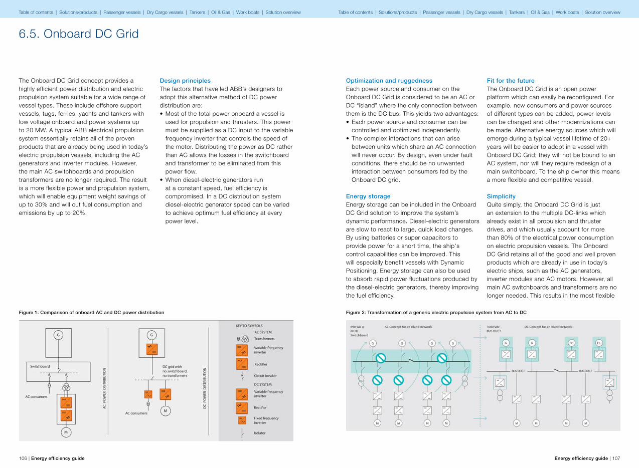
106 | Energy efficiency guide Energy efficiency guide | 107
6.5. Onboard DC Grid
The Onboard DC Grid concept provides a highly efficient power distribution and electric propulsion system suitable for a wide range of vessel types. These include offshore support vessels, tugs, ferries, yachts and tankers with low voltage onboard and power systems up to 20 MW. A typical ABB electrical propulsion system essentially retains all of the proven products that are already being used in today’s electric propulsion vessels, including the AC generators and inverter modules. However, the main AC switchboards and propulsion transformers are no longer required. The result is a more flexible power and propulsion system, which will enable equipment weight savings of up to 30% and will cut fuel consumption and emissions by up to 20%.
Design principlesThe factors that have led ABB’s designers to adopt this alternative method of DC power distribution are:• Most of the total power onboard a vessel is
used for propulsion and thrusters. This power must be supplied as a DC input to the variable frequency inverter that controls the speed of the motor. Distributing the power as DC rather than AC allows the losses in the switchboard and transformer to be eliminated from this power flow.
• When diesel-electric generators run at a constant speed, fuel efficiency is compromised. In a DC distribution system diesel-electric generator speed can be varied to achieve optimum fuel efficiency at every power level.
Figure 1: Comparison of onboard AC and DC power distribution
Optimization and ruggednessEach power source and consumer on the Onboard DC Grid is considered to be an AC or DC “island” where the only connection between them is the DC bus. This yields two advantages:• Each power source and consumer can be
controlled and optimized independently.• The complex interactions that can arise
between units which share an AC connection will never occur. By design, even under fault conditions, there should be no unwanted interaction between consumers fed by the Onboard DC grid.
Energy storageEnergy storage can be included in the Onboard DC Grid solution to improve the system’s dynamic performance. Diesel-electric generators are slow to react to large, quick load changes. By using batteries or super capacitors to provide power for a short time, the ship‘s control capabilities can be improved. This will especially benefit vessels with Dynamic Positioning. Energy storage can also be used to absorb rapid power fluctuations produced by the diesel-electric generators, thereby improving the fuel efficiency.
Fit for the futureThe Onboard DC Grid is an open power platform which can easily be reconfigured. For example, new consumers and power sources of different types can be added, power levels can be changed and other modernizations can be made. Alternative energy sources which will emerge during a typical vessel lifetime of 20+ years will be easier to adopt in a vessel with Onboard DC Grid; they will not be bound to an AC system, nor will they require redesign of a main switchboard. To the ship owner this means a more flexible and competitive vessel.
SimplicityQuite simply, the Onboard DC Grid is just an extension to the multiple DC-links which already exist in all propulsion and thruster drives, and which usually account for more than 80% of the electrical power consumption on electric propulsion vessels. The Onboard DC Grid retains all of the good and well proven products which are already in use in today’s electric ships, such as the AC generators, inverter modules and AC motors. However, all main AC switchboards and transformers are no longer needed. This results in the most flexible
Figure 2: Transformation of a generic electric propulsion system from AC to DC
Table of contents | Solutions/products | Passenger vessels | Dry Cargo vessels | Tankers | Oil & Gas | Work boats | Solution overview Table of contents | Solutions/products | Passenger vessels | Dry Cargo vessels | Tankers | Oil & Gas | Work boats | Solution overview
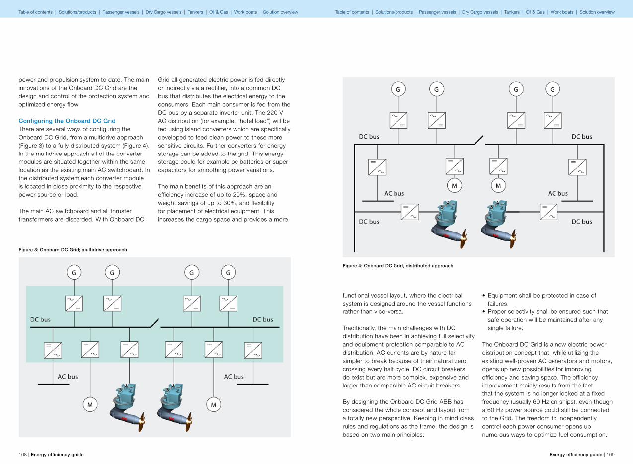
108 | Energy efficiency guide Energy efficiency guide | 109
power and propulsion system to date. The main innovations of the Onboard DC Grid are the design and control of the protection system and optimized energy flow.
Configuring the Onboard DC GridThere are several ways of configuring the Onboard DC Grid, from a multidrive approach (Figure 3) to a fully distributed system (Figure 4). In the multidrive approach all of the converter modules are situated together within the same location as the existing main AC switchboard. In the distributed system each converter module is located in close proximity to the respective power source or load.
The main AC switchboard and all thruster transformers are discarded. With Onboard DC
Grid all generated electric power is fed directly or indirectly via a rectifier, into a common DC bus that distributes the electrical energy to the consumers. Each main consumer is fed from the DC bus by a separate inverter unit. The 220 V AC distribution (for example, “hotel load”) will be fed using island converters which are specifically developed to feed clean power to these more sensitive circuits. Further converters for energy storage can be added to the grid. This energy storage could for example be batteries or super capacitors for smoothing power variations.
The main benefits of this approach are an efficiency increase of up to 20%, space and weight savings of up to 30%, and flexibility for placement of electrical equipment. This increases the cargo space and provides a more
Figure 3: Onboard DC Grid; multidrive approach
functional vessel layout, where the electrical system is designed around the vessel functions rather than vice-versa.
Traditionally, the main challenges with DC distribution have been in achieving full selectivity and equipment protection comparable to AC distribution. AC currents are by nature far simpler to break because of their natural zero crossing every half cycle. DC circuit breakers do exist but are more complex, expensive and larger than comparable AC circuit breakers.
By designing the Onboard DC Grid ABB has considered the whole concept and layout from a totally new perspective. Keeping in mind class rules and regulations as the frame, the design is based on two main principles:
• Equipment shall be protected in case of failures.
• Proper selectivity shall be ensured such that safe operation will be maintained after any single failure.
The Onboard DC Grid is a new electric power distribution concept that, while utilizing the existing well-proven AC generators and motors, opens up new possibilities for improving efficiency and saving space. The efficiency improvement mainly results from the fact that the system is no longer locked at a fixed frequency (usually 60 Hz on ships), even though a 60 Hz power source could still be connected to the Grid. The freedom to independently control each power consumer opens up numerous ways to optimize fuel consumption.
Figure 4: Onboard DC Grid, distributed approach
Table of contents | Solutions/products | Passenger vessels | Dry Cargo vessels | Tankers | Oil & Gas | Work boats | Solution overview Table of contents | Solutions/products | Passenger vessels | Dry Cargo vessels | Tankers | Oil & Gas | Work boats | Solution overview
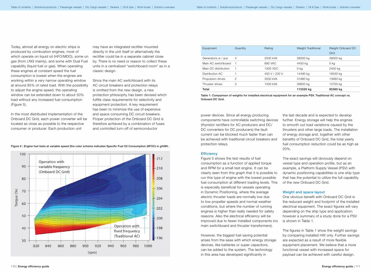
110 | Energy efficiency guide Energy efficiency guide | 111
Today, almost all energy on electric ships is produced by combustion engines, most of which operate on liquid oil (HFO/MDO), some on gas (from LNG mainly), and some with Dual Fuel capability (liquid fuel or gas). When operating these engines at constant speed the fuel consumption is lowest when the engines are working within a very narrow operating window at around 85% of rated load. With the possibility to adjust the engine speed, the operating window can be extended down to about 50% load without any increased fuel consumption (Figure 5).
In the most distributed implementation of the Onboard DC Grid, each power converter will be located as close as possible to the respective consumer or producer. Each production unit
may have an integrated rectifier mounted directly in the unit itself or alternatively the rectifier could be in a separate cabinet close by. There is no need or reason to collect these units in a centralized “switchboard room” as in a classic design.
Since the main AC switchboard with its AC circuit breakers and protection relays is omitted from the new design, a new protection philosophy has been devised which fulfills class requirements for selectivity and equipment protection. A key requirement has been to minimize the use of expensive and space consuming DC circuit breakers. Proper protection of the Onboard DC Grid is therefore achieved by a combination of fuses and controlled turn-off of semiconductor
Figure 5 : Engine fuel tests at variable speed (the color scheme indicates Specific Fuel Oil Consumption (SFOC) in g/kWh .
power devices. Since all energy producing components have controllable switching devices (thyristor rectifiers for AC producers and DC/DC converters for DC producers) the fault current can be blocked much faster than can be achieved with traditional circuit breakers and protection relays.
EfficiencyFigure 5 shows the test results of fuel consumption as a function of applied torque and RPM for a small test engine. It can be clearly seen from this graph that it is possible to run this type of engine with the lowest possible fuel consumption at different loading levels. This is especially beneficial for vessels operating in Dynamic Positioning, where the average electric thruster loads are normally low due to low propeller speeds and normal weather conditions, but where the number of running engines is higher than really needed for safety reasons. Also the electrical efficiency will be improved due to fewer installed components (no main switchboard and thruster transformers).
However, the biggest fuel saving potential arises from the ease with which energy storage devices, like batteries or super capacitors, can be added to the system. The technology in this area has developed significantly in
the last decade and is expected to develop further. Energy storage will help the engines to smooth out load variations caused by the thrusters and other large loads. The installation of energy storage and, together with other benefits of Onboard DC Grid, the total yearly fuel consumption reduction could be as high as 20%.
The exact savings will obviously depend on vessel type and operation profile, but as an example, a Platform Supply Vessel (PSV) with dynamic positioning capabilities is one ship type that has the potential to utilize the full capability of the new Onboard DC Grid.
Weight and space layoutOne obvious benefit with Onboard DC Grid is the reduced weight and footprint of the installed electrical equipment. The exact figures will vary depending on the ship type and application; however a summary of a study done for a PSV is shown in Table 1.
The figures in Table 1 show the weight savings by comparing installed HW only. Further savings are expected as a result of more flexible equipment placement. We believe that a more functional vessel with increased space for payload can be achieved with careful design.
Equipment Quantity Rating Weight Traditional Weight Onboard DC
Grid
Generators w / aux 4 2500 kVA 38000 kg 39000 kg
Main AC switchboard 1 690 VAC 4450 kg 0 kg
Main DC distribution 1 1000 VDC 0 kg 2400 kg
Distribution AC 1 450 V / 230 V 14490 kg 16530 kg
Propulsion drives 2 3500 kVA 31980 kg 13680 kg
Thruster drives 3 1200 kVA 26600 kg 13750 kg
Total 115520 kg 85360 kg
Table 1: Comparison of weights for installed electrical equipment for an example PSV. Traditional AC concept vs. Onboard DC Grid.
Table of contents | Solutions/products | Passenger vessels | Dry Cargo vessels | Tankers | Oil & Gas | Work boats | Solution overview Table of contents | Solutions/products | Passenger vessels | Dry Cargo vessels | Tankers | Oil & Gas | Work boats | Solution overview

112 | Energy efficiency guide Energy efficiency guide | 113
OperationThe Onboard DC Grid enables new ways of thinking about operational optimization. As the system is flexible by combining different energy sources such as engines, turbines and fuel cells, there is huge potential to implement a real energy management system, which takes into account variations in fuel prices and availability of different fuels. This kind of optimization may still be some years away, but with the Onboard DC Grid the vessel is prepared to incorporate electricity-producing energy technologies that may become available within the next decade.
With today’s technology, it is possible to solve many of the traditional challenges of dynamic positioning operation by running engines at part load. For safety reasons, in the most severe DP operations today, the electrical plant is most often operated as a 2-split configuration. This allows the vessel to maintain its position even if one side of the power plant fails. However, running in split mode does not make the most of electric propulsion in general because total
optimization of running engines is not possible. With Onboard DC Grid, split mode operation can be more efficient because the engine speed can be adjusted and optimized to the required load without having to change the number of generators in operation.
Protection and safetyAs previously stated the protection philosophy is based on a combination of fuses and controlled switches. In short; fuses are used to protect and isolate inverter modules in case of serious module faults. The same philosophy is applied to the current low voltage frequency converters. In addition, input circuits isolate the inverter modules from the main DC bus and afford full control of reverse power, both in fault and normal conditions (as for example in propeller braking mode). This means that faults at a single consumer will not affect other consumers connected to the main DC distribution system. In the event of severe faults on the distributed DC bus itself, the system is protected from generators by means of a controllable thyristor
Figure 6: Dina Star, the first vessel with Onboard DC Grid.
Increase the efficiency by up to 20% and reduce the footprint of electrical equipment by up to 30%.
Onboard DC GridA significant step forward in electric propulsion increasing vessel efficiency by up to 20%
The Onboard DC Grid will allow any new DC energy source, such as batteries and fuel cells, to be simply plugged into the system. Vessels using electric propulsion and diesel engines as their primary power source will then be able to maintain optimum energy efficiency in the future as new technology, regulations and fuel prices change over the next 20 years. This will protect your investment in the long term, and in the short term the Onboard DC Grid will save space, completely eliminate some components and reduce fuel consumption and emissions by up to 20%.
rectifier which also doubles as a protection device for the generator. Isolators are installed in each circuit branch in order to automatically isolate faulty sections from the healthy system.
In summary, the Onboard DC Grid fully complies with rules and regulations for selectivity and equipment protection. Furthermore, any fault current will be cleared within maximum 40 ms. This means much lower Onboard DC Grid fault energy levels when compared to traditional AC protection circuits where fault durations can reach up to 1 s. This low energy fault protection scheme enables the Onboard DC Grid system to be used for applications up to at least 20 MW.
BenefitsThe Onboard DC Grid system is a new way of distributing energy for low voltage installations in ships. It can be used for any electrical ship application up to at least 20 MW and operates at a nominal voltage of 1,000 V DC. The power distribution can be arranged where all cabinets are in a single line up (multidrive approach) or can be distributed throughout the vessel by using a short-circuit proof DC bus.
Benefits for the ship owner• Up to 20% fuel saving when taking full
advantage of all of the features, including energy storage and variable speed engines.
• Reduced methane slip for gas engines at low load.
• Reduced maintenance of engines as a consequence of more efficient operation.
• Improved dynamic response by using energy storage, which may give a better Dynamic Positioning (DP) performance with lower fuel consumption or more accurate positioning.
• More functional vessel layout because electrical components can be placed more flexibly.
• A system platform that enables simple “plug and play” retrofitting possibilities to adapt to future energy sources.
Benefits for the shipyard and designers• More flexible placement of electric
components.• Reduced footprint and up to 30% weight
saving of electrical equipment • Less cabling and connections, thanks to the
use of bus ducts and fewer components.
Even though the use of bus ducts is a relatively new type of installation work for many shipyards, several benefits can also be listed for this. These include: Reduced cross section, no bending radius, and significant reduction of fire load compared to traditional cables.
SavingsOnboard DC Grid enables a saving in equipment footprint and weight of up to 30% together with a reduction of fuel consumption and emissions of up to 20%.
Table of contents | Solutions/products | Passenger vessels | Dry Cargo vessels | Tankers | Oil & Gas | Work boats | Solution overview Table of contents | Solutions/products | Passenger vessels | Dry Cargo vessels | Tankers | Oil & Gas | Work boats | Solution overview
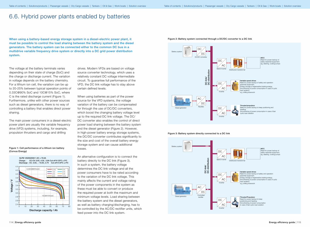
114 | Energy efficiency guide Energy efficiency guide | 115
6.6. Hybrid power plants enabled by batteries
When using a battery-based energy storage system in a diesel-electric power plant, it must be possible to control the load sharing between the battery system and the diesel generators. The battery system can be connected either to the common DC bus in a multidrive variable frequency drive system or directly into a DC grid power distribution system.
The voltage at the battery terminals varies depending on their state of charge (SoC) and the charge or discharge current. The variation in voltage depends on the battery chemistry. For a lithium ion cell, the variation can be up to 20-25% between typical operation points of 0.33C@90% SoC and 10C@15% SoC, where C is the rated discharge current (Figure 1). Furthermore, unlike with other power sources such as diesel generators, there is no way of controlling a battery that enables direct power sharing.
The main power consumers in a diesel-electric power plant are usually the variable frequency drive (VFD) systems, including, for example, propulsion thrusters and cargo and drilling
drives. Modern VFDs are based on voltage source converter technology, which uses a relatively constant DC voltage intermediate circuit. To guarantee full performance of the VFD, the DC link voltage has to stay above certain defined levels.
When using batteries as part of the power source for the VFD systems, the voltage variation of the battery can be compensated for through the use of DC/DC converters, which boost the changing battery voltage level up to the required DC link voltage. The DC/DC converter also enables the control of direct power load sharing between the battery system and the diesel generator (Figure 2). However, in high-power battery energy storage systems, the DC/DC converter contributes significantly to the size and cost of the overall battery energy storage system and can cause additional losses.
An alternative configuration is to connect the battery directly to the DC link (Figure 3).In such a system, the battery voltage determines the DC link voltage and all the power consumers have to be rated according to the variation of the DC link voltage. This mainly affects the current and voltage rating of the power components in the system as these must be able to convert or produce the required power at both the maximum and minimum voltage levels. Load sharing between the battery system and the diesel generators, as well as battery charging/discharging, has to be controlled by the AC/DC rectifier units, which feed power into the DC link system.
Discharge capacity / Ah
Volta
ge
/ V
10C@15%5oC
0,33C@90%5oC
2.4
2.6
2.8
3.0
3.2
3.4
3.6
3.8
4.0
4.2
4.4
0 10 20 30 40 50 60 70 80
0,33C 0,5C1,0C 2,0C3,0C 5,0C8,0C 10,0C
SLPB 125255255H 1.0C = 70.0A
CC. 0.5C, ~ 10.0C, 2.7V Cut-off @ 23ºC ± 3ºCCC-CV. 0.5C, 4.2V, 3.5A Cut-off @ 23ºC ± 3ºCCharge :
Discharge :
Figure 1: Cell performance of a lithium ion battery (Corvus Energy)
Figure 2: Battery system connected through a DC/DC converter to a DC link
Figure 3: Battery system directly connected to a DC link
DC
DC
AC
DC
DC
AC
DC
AC
DC
AC
DC
-lin
k/D
C-d
istr
ibut
ion
Battery system
Diesel generatorRecti�er
DC/DC converter
Island InverterDistribution transformer
Inverter
Inverter
MCCNeed for power backup of safety essential equipment;eg, steering, cooling pumps
Variable speed drivesNeed for power backup of safety and operation essential equipment;Energy storage of regenerative braking energy;Smoothening of power consumption in case of cyclic load variation;e.g. drilling drawwork
Thruster/propulsionNeed for power backup to keep positioning and heading;Smoothening of power consumption in case of fast cyclic load variation
Bat
tery
AC
DC
DC
AC
DC
AC
DC
ACD
C-l
ink/
DC
-dis
trib
utio
n
Battery system
Diesel generatorControlledrecti�er
Island inverterDistribution transformer
Inverter
Inverter
MCCNeed for power backup of safety essential equipment;eg, steeting, cooling pumps
Variable speed drivesNeed for power backup of safety and operation essential equipment;Energy storage of regenerative braking energy;Smoothening of power consumption in case of cyclic load variation;e.g. drilling drawwork
Thruster/PropulsionNeed for power backup to keep positioning and heading;Smoothening of power consumption in case of fast cyclic load variation
Bat
tery
Table of contents | Solutions/products | Passenger vessels | Dry Cargo vessels | Tankers | Oil & Gas | Work boats | Solution overview Table of contents | Solutions/products | Passenger vessels | Dry Cargo vessels | Tankers | Oil & Gas | Work boats | Solution overview

116 | Energy efficiency guide Energy efficiency guide | 117
In applications with a high C-rate discharge current, the natural droop of the battery voltage can be used for load sharing between a diesel generator set and the battery. The voltage droop (cell voltage versus discharge current) is relatively linear but changes with the SoC of the battery (Figure 4).
Voltage droop based load sharing is an effective and robust method for parallel operating power sources. With the DC voltage common for both the battery and the rectifier, each unit supplies the amount of power which corresponds to its applied droop curve. As the load on the DC link increases, the DC voltage drops.
By implementing a voltage droop control algorithm in the rectifier control system, the output voltage of the rectifier can be adjusted to control the power flow in both the battery and the AC/DC rectifier and consequently between the battery and the diesel generator (Figure 5). The natural droop curve of the battery is only quasi-static and changes with the SoC. With current and SoC feedback from the battery management controller, a load sharing controller can adjust the voltage reference and droop curve settings of the droop controller in the controlled rectifier. By adjusting the voltage reference and droop curve setting in the droop controller, not only can the load sharing between the battery and diesel generator be controlled, but also the battery charging.
4,2
4
3,8
3,6
3,4
3,2
30 2 4 6 8 10
Battery voltage droop
C rated discharge
Cel
l vo
ltag
e [V
]
Cell voltage @ 10Ah
Cell voltage @ 50Ah
980
960
940
920
900
880
860
20 40 60 80 100
DC
-vol
tage
[V]
Battery d roop curve
Controlled rectifier d roop curve
Example:Battery nominal voltage@SoC = 960VBattery natural voltage droop@SoC = 10%
Load [%]
Figure 4: Battery voltage droop
Figure 5: Voltage droop based load sharing
Benefits:• Reduced fuel consumption.• Reduced emissions.• Improved dynamic response of the power
plant.• Increased power plant availability due to the
instantaneous availability of energy backup source.
The marine market is evaluating concepts based on the use of hybrid power plants with energy storage systems.
Figure 6: Contolled rectifier voltage droop control
Power Feedback
Battery SoC&Current Feedback
DC Voltage Feedback
Voltage reference and droop can be adjusted by Load Sharing Control System
Droop
BatteryManagement
Recti�er Control
Recti�erPI+
-
-
Load Sharing Control
Voltage Reference
Table of contents | Solutions/products | Passenger vessels | Dry Cargo vessels | Tankers | Oil & Gas | Work boats | Solution overview Table of contents | Solutions/products | Passenger vessels | Dry Cargo vessels | Tankers | Oil & Gas | Work boats | Solution overview
118 | Energy efficiency guide Energy efficiency guide | 119
6.7. Variable frequency drive for shaft generator (PTO/PTI)
Shaft generators are commonly used to produce electrical power for the ship’s network, in vessels equipped with a conventional propulsion system, where a mechanical shaft is driven by a slow or medium speed engine. Shaft generators are used to reduce the loading of diesel generator sets, by generating power in parallel with them, or to provide all of the required power, which enables the shutdown of the auxiliary engines.
• Shaft generators with frequency control by electrical means – An AC generator supplying the static inverter system is utilized in the vast majority of cases, although alternative methods are also available
– Synchronous or asynchronous generator & motor/alternator set
– Full generator output is available at a wider range of main engine rotation speeds
– In most cases, parallel running with generator sets is possible
• Shaft generators with frequency control by mechanical means – A few installations, where a constant frequency is obtained using a variable ratio epicyclical gearbox
– Advantages and investment cost are more or less the same as for electrical alternatives
– The main disadvantage is the complexity of the gearbox hydraulic control system, which tends to be less reliable than electrical frequency control
The challengeWhen aiming for lower fuel consumption, one of the most efficient methods involves decreasing the required propulsion/shaft power by reducing the vessel speed. However, a reduction in vessel speed sets limitations on shaft generator systems not equipped with frequency control.
Limited flexibility without frequency controlAround 70% of world’s merchant fleet comprises slow speed engine powered vessels; most of these are equipped with FPP. Many of these vessels are equipped with shaft
If the vessel is equipped with controllable pitch propeller (CPP), while maneuvering in port a shaft generator is typically used to supply power to the thrusters, since the power output of diesel generator sets is usually insufficient to meet high power demand from the thrusters.
However, the system’s design often places restrictions on how and under what conditions the shaft generator can be used to generate electricity. This depends on a number of factors associated with onboard configuration, such as:• Mounting arrangement of the shaft generator
(at the front end of the engine, the side of the engine, or aft of the engine)
• Connection of the shaft generator; via a step up gear or directly onto the propeller shaft.
• Propeller system of the vessel; fixed pitch propeller (FPP) or controllable pitch propeller (CPP)
• Operational profile of the vessel
Shaft generator typesGenerally speaking, there are three types of shaft generator arrangements on board a vessel.• Shaft generators without frequency control
– The simplest and thereby the cheapest shaft generator
– Since the AC generator frequency depends on the rotation speed, these generators must be run at a constant RPM
– Floating frequency is basically possible (i.e. between 50 and 60 Hz)
– Cannot be run parallel with diesel generator sets, even with CPP
– Narrow operational window, depending on the propeller system/type.
generators without frequency control. Such a combination does not allow flexible use of the shaft generator.
2-stroke engine with FPP – no flexibility in using the shaft generatorThese vessels are typically oceangoing, operating on long-distance voyages at low speeds. On such vessels, the shaft generator is mainly used on open seas, in order to generate power for the hotel and cargo load.
Since the frequency of the electrical power produced by the shaft generator depends on the rotation speed, the main engine RPM must be kept constant. These systems are designed for operation of the shaft generator at or close to the vessel’s design speed, at which the propulsion system has optimum efficiency. If the vessel’s operational profile changes significantly (with an emphasis on lower speeds) or if the vessel shifts to slow steaming, due to the resulting fall in the main engine’s RPM the shaft generator cannot be used for power production. 2-stroke engine with CPP – limited flexibility in using the shaft generatorThese vessels are typically oceangoing vessels, in which the shaft generator is operated at a constant engine RPM at varying vessel speeds. The shaft generator is mainly used to generate power for the hotel and cargo load, and for thrusters during harbor maneuvering.
With CPP, the classic approach to maintaining vessel speed is based on operating the vessel according to the combinator curve, a pre-set combination of propeller pitch and engine/shaft RPM i.e. so-called combinator control. This enables the highest possible efficiency during propulsion. However, due to a variable main engine RPM; the shaft generator cannot be used with combinator control.
In the case of CPP equipped vessels, instead of using combinator control, it is possible to maintain the vessel’s speed by altering only the propeller pitch and keeping the main engine RPM constant. This enables use of the shaft generator at reduced vessel speeds. However, a constant RPM mode has several disadvantages compared to combinator control, leading to higher running costs. Using a constant RPM mode with CPP leads to higher fuel consumption by the main engine, because the shaft generator is used for power production. Another major drawback lies in the fast rotating propeller with a low blade pitch. This leads to inefficiency in propulsion, causing additional losses and, in the worst case scenario, cavitation of the propeller.
How to improve flexibility in shaft generator operationA major improvement can be made in the shaft generator’s operational flexibility, by retrofitting a variable frequency drive (VFD) in order to control the output of the shaft generator. In the case of FPP, use of a shaft generator is not tied to the ship design speed/constant main engine RPM, since the VFD enables the system to be designed in such a way that full shaft generator output is available across a wider range of main engine rotation speeds.
In the case of CPP, VFD enables running the main engine and propeller with combinator control at lower speeds too. This maintains optimum propeller efficiency and fuel consumption.
Most existing shaft generators can be modified and retrofitted to include the VFD, in order to increase their operational flexibility.
The system can be used to produce benefits in addition to increasing the operating window of the shaft generator, as illustrated in Figure 1.
Table of contents | Solutions/products | Passenger vessels | Dry Cargo vessels | Tankers | Oil & Gas | Work boats | Solution overview Table of contents | Solutions/products | Passenger vessels | Dry Cargo vessels | Tankers | Oil & Gas | Work boats | Solution overview

Boost
Electric
Mechanic Electric
Combinator CPP Combinator
Mechanic
Mechanic
Electric
Propulsion Load
Pri
me
mo
ver
Load
• Fixed RPM• Variable Pitch
• Fixed RPM• Variable Pitch
• Variable RPM• Variable Pitch
120 | Energy efficiency guide Energy efficiency guide | 121
Fully electric propulsionIn the case of low speed operation, such as standby or awaiting a port call, the shaft generator, now working as an electrical motor (Power Take-In (PTI)), can be used as a propulsion motor, drawing its electrical power from the auxiliary engines. The main engine can be stopped.
Normal operating conditionsIn normal operating conditions, regardless of whether or not the vessel is operating at its design speed, the shaft generator and VFD can produce the required electricity for the vessel. Use of ABB’s VFD solution enables island operation, whereby the shaft generator generates the entire electric load itself. Alternatively, parallel mode, involving a combination of shaft generator and onboard auxiliary engines, can be used.
“Parallel hybrid”An alternative to the full electrical solution is a combination of mechanical and electric propulsion systems – the so-called hybrid propulsion system. Because electrical and mechanical propulsion systems work in parallel through the gearbox, this is also known as the “parallel hybrid”. This mode is most beneficial when the complete power plant is built bearing this mode in mind. The advantages of a retrofit are questionable, since the existing main engine is already dimensioned based on the design criteria. Using this mode also enables full use of the waste heat recovery system (WHRS), because excess power from the steam can be used to power the propulsion system.
Shore-to-ship electrical connectionThe auxiliary engines of ships run in ports produce SOX, NOX, CO2 and particle discharges, as well as noise and vibration. These pollutants have a negative health and environmental impact on the surrounding communities.
With the ABB VFD solution for shaft generators, ships can shut down their auxiliary engines while berthed and plug into an onshore power source, thereby eliminating emissions into the local surroundings. The ship’s power load can be transferred to the shore-side power source, in a secured and automated manner, without disrupting onboard services.
VFD for shaft generators as part of a new ship designBased on ABB’s power concept for large container vessels, in addition to the main diesel engine, three power generators are used: the power/steam turbine generator, the shaft generator/motor and the auxiliary power plant, normally consisting of three or four generator sets.
Figure 1: The various operating modes of the onboard shaft generator
Depending on the ship’s operating conditions, electricity production from the different power sources will vary. The goal is always to maximize the use of cost-effective green energy sources.
Operating modesThe shaft generator/motor has two different operating modes. In Power Take-In (PTI) mode, the generator is used as a propulsion motor for boosting the main engine, and in Power Take-Off (PTO) mode it is used as an electricity generator. Automatic switching between these modes maximizes the use of green energy from the WHRS and shaft generator/motor system.
Whenever the WHRS generates more electricity than the vessel can consume, or when the main engine requires extra power, the system operates in PTI mode, feeding energy into the drive shaft of the vessel’s propulsion system.
When demand for onboard electricity rises, the shaft generator/motor automatically switches to PTO mode, feeding power into the vessel’s electricity grid. Power produced by this generator, which is already rotating on the main shaft, is much more energy-efficient than power generated by auxiliary generator sets.
Figure 2: A typical system configura-tion for a container vessel with WHRS and a shaft generator/motor system
Table of contents | Solutions/products | Passenger vessels | Dry Cargo vessels | Tankers | Oil & Gas | Work boats | Solution overview Table of contents | Solutions/products | Passenger vessels | Dry Cargo vessels | Tankers | Oil & Gas | Work boats | Solution overview
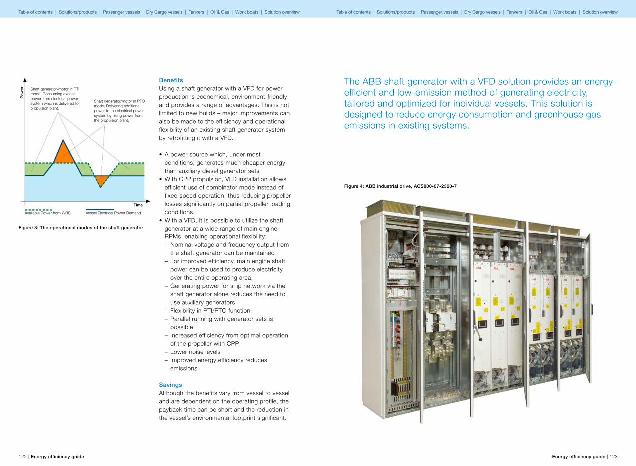
Shaft generator/motor in PTI mode. Consuming excess power from electrical power system which is delivered to propulsion plant.
Shaft generator/motor in PTO mode. Delivering additional power to the electrical power system by using power from the propulsion plant.
Time
Vessel Electrical Power DemandAvailable Power from WRS
Po
wer
122 | Energy efficiency guide Energy efficiency guide | 123
BenefitsUsing a shaft generator with a VFD for power production is economical, environment-friendly and provides a range of advantages. This is not limited to new builds – major improvements can also be made to the efficiency and operational flexibility of an existing shaft generator system by retrofitting it with a VFD.
• A power source which, under most conditions, generates much cheaper energy than auxiliary diesel generator sets
• With CPP propulsion, VFD installation allows efficient use of combinator mode instead of fixed speed operation, thus reducing propeller losses significantly on partial propeller loading conditions.
• With a VFD, it is possible to utilize the shaft generator at a wide range of main engine RPMs, enabling operational flexibility: – Nominal voltage and frequency output from the shaft generator can be maintained
– For improved efficiency, main engine shaft power can be used to produce electricity over the entire operating area,
– Generating power for ship network via the shaft generator alone reduces the need to use auxiliary generators
– Flexibility in PTI/PTO function – Parallel running with generator sets is possible
– Increased efficiency from optimal operation of the propeller with CPP
– Lower noise levels – Improved energy efficiency reduces emissions
Savings Although the benefits vary from vessel to vessel and are dependent on the operating profile, the payback time can be short and the reduction in the vessel’s environmental footprint significant.
Figure 3: The operational modes of the shaft generator
The ABB shaft generator with a VFD solution provides an energy-efficient and low-emission method of generating electricity, tailored and optimized for individual vessels. This solution is designed to reduce energy consumption and greenhouse gas emissions in existing systems.
Figure 4: ABB industrial drive, ACS800-07-2320-7
Table of contents | Solutions/products | Passenger vessels | Dry Cargo vessels | Tankers | Oil & Gas | Work boats | Solution overview Table of contents | Solutions/products | Passenger vessels | Dry Cargo vessels | Tankers | Oil & Gas | Work boats | Solution overview
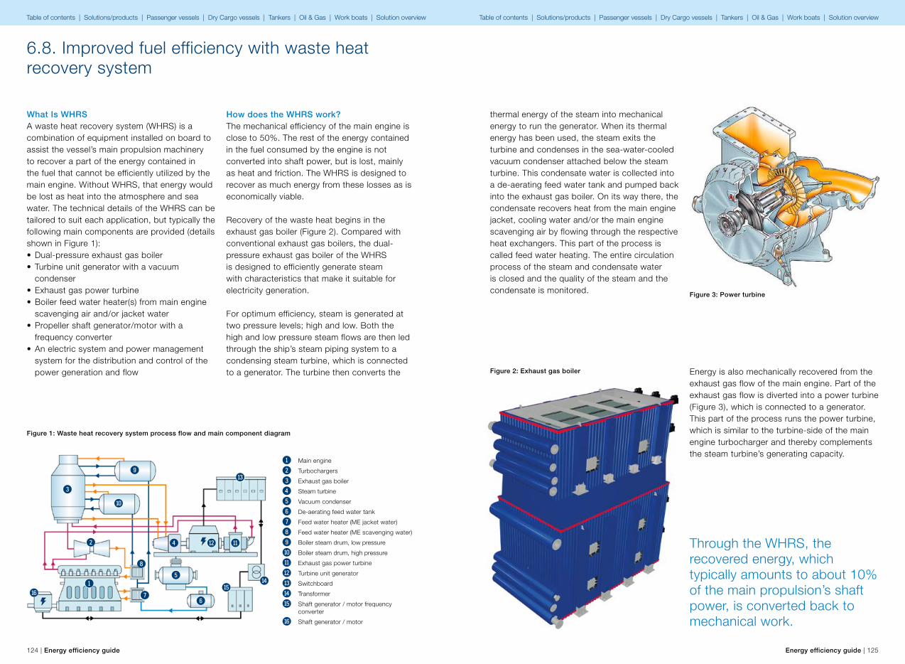
124 | Energy efficiency guide Energy efficiency guide | 125
What Is WHRSA waste heat recovery system (WHRS) is a combination of equipment installed on board to assist the vessel’s main propulsion machinery to recover a part of the energy contained in the fuel that cannot be efficiently utilized by the main engine. Without WHRS, that energy would be lost as heat into the atmosphere and sea water. The technical details of the WHRS can be tailored to suit each application, but typically the following main components are provided (details shown in Figure 1):• Dual-pressure exhaust gas boiler• Turbine unit generator with a vacuum
condenser• Exhaust gas power turbine• Boiler feed water heater(s) from main engine
scavenging air and/or jacket water• Propeller shaft generator/motor with a
frequency converter• An electric system and power management
system for the distribution and control of the power generation and flow
How does the WHRS work?The mechanical efficiency of the main engine is close to 50%. The rest of the energy contained in the fuel consumed by the engine is not converted into shaft power, but is lost, mainly as heat and friction. The WHRS is designed to recover as much energy from these losses as is economically viable.
Recovery of the waste heat begins in the exhaust gas boiler (Figure 2). Compared with conventional exhaust gas boilers, the dual-pressure exhaust gas boiler of the WHRS is designed to efficiently generate steam with characteristics that make it suitable for electricity generation.
For optimum efficiency, steam is generated at two pressure levels; high and low. Both the high and low pressure steam flows are then led through the ship’s steam piping system to a condensing steam turbine, which is connected to a generator. The turbine then converts the
6.8. Improved fuel efficiency with waste heat recovery system
Figure 1: Waste heat recovery system process flow and main component diagram
1 Main engine
2 Turbochargers
3 Exhaust gas boiler
4 Steam turbine
5 Vacuum condenser
6 De-aerating feed water tank
7 Feed water heater (ME jacket water)
8 Feed water heater (ME scavenging water)
9 Boiler steam drum, low pressure
q Boiler steam drum, high pressure
w Exhaust gas power turbine
e Turbine unit generator
r Switchboard
t Transformer
y Shaft generator / motor frequency converter
u Shaft generator / motor
1
2
3
4
5
67
8
9
q
we
r
ty
u
thermal energy of the steam into mechanical energy to run the generator. When its thermal energy has been used, the steam exits the turbine and condenses in the sea-water-cooled vacuum condenser attached below the steam turbine. This condensate water is collected into a de-aerating feed water tank and pumped back into the exhaust gas boiler. On its way there, the condensate recovers heat from the main engine jacket, cooling water and/or the main engine scavenging air by flowing through the respective heat exchangers. This part of the process is called feed water heating. The entire circulation process of the steam and condensate water is closed and the quality of the steam and the condensate is monitored.
Energy is also mechanically recovered from the exhaust gas flow of the main engine. Part of the exhaust gas flow is diverted into a power turbine (Figure 3), which is connected to a generator. This part of the process runs the power turbine, which is similar to the turbine-side of the main engine turbocharger and thereby complements the steam turbine’s generating capacity.
Figure 2: Exhaust gas boiler
Figure 3: Power turbine
Through the WHRS, the recovered energy, which typically amounts to about 10% of the main propulsion’s shaft power, is converted back to mechanical work.
Table of contents | Solutions/products | Passenger vessels | Dry Cargo vessels | Tankers | Oil & Gas | Work boats | Solution overview Table of contents | Solutions/products | Passenger vessels | Dry Cargo vessels | Tankers | Oil & Gas | Work boats | Solution overview
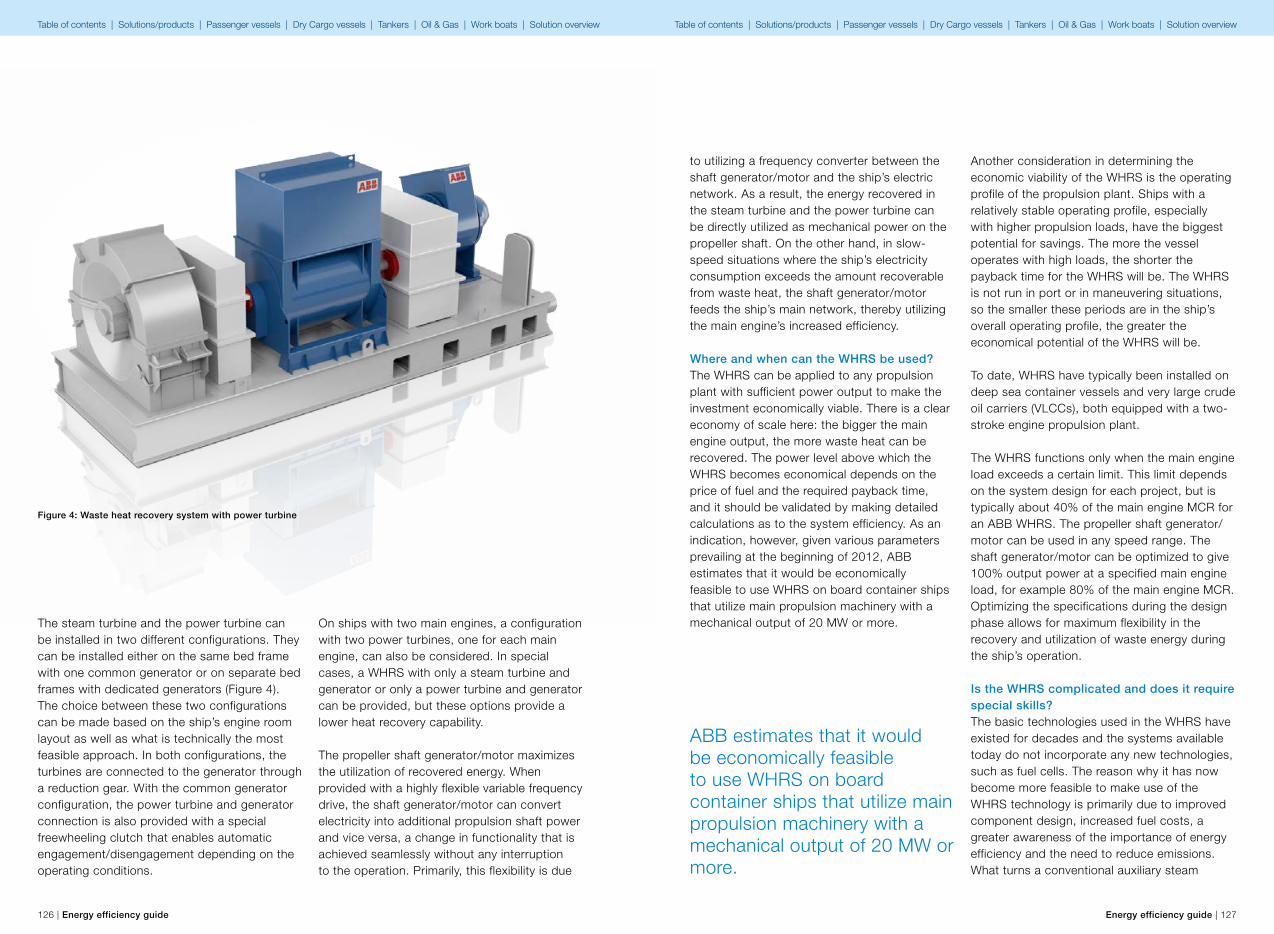
126 | Energy efficiency guide Energy efficiency guide | 127
The steam turbine and the power turbine can be installed in two different configurations. They can be installed either on the same bed frame with one common generator or on separate bed frames with dedicated generators (Figure 4). The choice between these two configurations can be made based on the ship’s engine room layout as well as what is technically the most feasible approach. In both configurations, the turbines are connected to the generator through a reduction gear. With the common generator configuration, the power turbine and generator connection is also provided with a special freewheeling clutch that enables automatic engagement/disengagement depending on the operating conditions.
On ships with two main engines, a configuration with two power turbines, one for each main engine, can also be considered. In special cases, a WHRS with only a steam turbine and generator or only a power turbine and generator can be provided, but these options provide a lower heat recovery capability.
The propeller shaft generator/motor maximizes the utilization of recovered energy. When provided with a highly flexible variable frequency drive, the shaft generator/motor can convert electricity into additional propulsion shaft power and vice versa, a change in functionality that is achieved seamlessly without any interruption to the operation. Primarily, this flexibility is due
Figure 4: Waste heat recovery system with power turbine
to utilizing a frequency converter between the shaft generator/motor and the ship’s electric network. As a result, the energy recovered in the steam turbine and the power turbine can be directly utilized as mechanical power on the propeller shaft. On the other hand, in slow-speed situations where the ship’s electricity consumption exceeds the amount recoverable from waste heat, the shaft generator/motor feeds the ship’s main network, thereby utilizing the main engine’s increased efficiency.
Where and when can the WHRS be used?The WHRS can be applied to any propulsion plant with sufficient power output to make the investment economically viable. There is a clear economy of scale here: the bigger the main engine output, the more waste heat can be recovered. The power level above which the WHRS becomes economical depends on the price of fuel and the required payback time, and it should be validated by making detailed calculations as to the system efficiency. As an indication, however, given various parameters prevailing at the beginning of 2012, ABB estimates that it would be economically feasible to use WHRS on board container ships that utilize main propulsion machinery with a mechanical output of 20 MW or more.
Another consideration in determining the economic viability of the WHRS is the operating profile of the propulsion plant. Ships with a relatively stable operating profile, especially with higher propulsion loads, have the biggest potential for savings. The more the vessel operates with high loads, the shorter the payback time for the WHRS will be. The WHRS is not run in port or in maneuvering situations, so the smaller these periods are in the ship’s overall operating profile, the greater the economical potential of the WHRS will be.
To date, WHRS have typically been installed on deep sea container vessels and very large crude oil carriers (VLCCs), both equipped with a two-stroke engine propulsion plant.
The WHRS functions only when the main engine load exceeds a certain limit. This limit depends on the system design for each project, but is typically about 40% of the main engine MCR for an ABB WHRS. The propeller shaft generator/motor can be used in any speed range. The shaft generator/motor can be optimized to give 100% output power at a specified main engine load, for example 80% of the main engine MCR. Optimizing the specifications during the design phase allows for maximum flexibility in the recovery and utilization of waste energy during the ship’s operation.
Is the WHRS complicated and does it require special skills?The basic technologies used in the WHRS have existed for decades and the systems available today do not incorporate any new technologies, such as fuel cells. The reason why it has now become more feasible to make use of the WHRS technology is primarily due to improved component design, increased fuel costs, a greater awareness of the importance of energy efficiency and the need to reduce emissions. What turns a conventional auxiliary steam
ABB estimates that it would be economically feasible to use WHRS on board container ships that utilize main propulsion machinery with a mechanical output of 20 MW or more.
Table of contents | Solutions/products | Passenger vessels | Dry Cargo vessels | Tankers | Oil & Gas | Work boats | Solution overview Table of contents | Solutions/products | Passenger vessels | Dry Cargo vessels | Tankers | Oil & Gas | Work boats | Solution overview
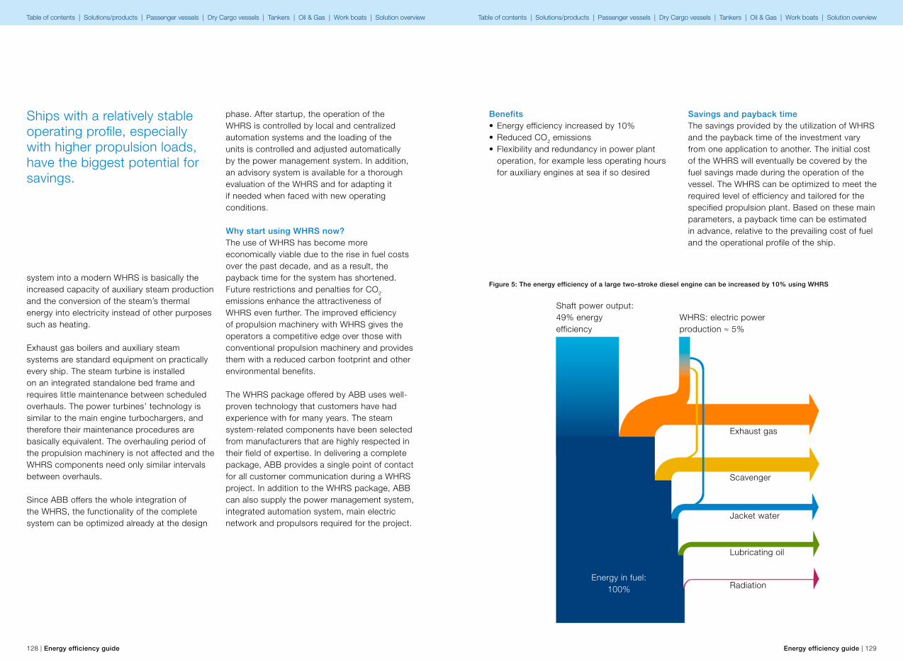
128 | Energy efficiency guide Energy efficiency guide | 129
system into a modern WHRS is basically the increased capacity of auxiliary steam production and the conversion of the steam’s thermal energy into electricity instead of other purposes such as heating.
Exhaust gas boilers and auxiliary steam systems are standard equipment on practically every ship. The steam turbine is installed on an integrated standalone bed frame and requires little maintenance between scheduled overhauls. The power turbines’ technology is similar to the main engine turbochargers, and therefore their maintenance procedures are basically equivalent. The overhauling period of the propulsion machinery is not affected and the WHRS components need only similar intervals between overhauls.
Since ABB offers the whole integration of the WHRS, the functionality of the complete system can be optimized already at the design
phase. After startup, the operation of the WHRS is controlled by local and centralized automation systems and the loading of the units is controlled and adjusted automatically by the power management system. In addition, an advisory system is available for a thorough evaluation of the WHRS and for adapting it if needed when faced with new operating conditions.
Why start using WHRS now?The use of WHRS has become more economically viable due to the rise in fuel costs over the past decade, and as a result, the payback time for the system has shortened. Future restrictions and penalties for CO2 emissions enhance the attractiveness of WHRS even further. The improved efficiency of propulsion machinery with WHRS gives the operators a competitive edge over those with conventional propulsion machinery and provides them with a reduced carbon footprint and other environmental benefits.
The WHRS package offered by ABB uses well-proven technology that customers have had experience with for many years. The steam system-related components have been selected from manufacturers that are highly respected in their field of expertise. In delivering a complete package, ABB provides a single point of contact for all customer communication during a WHRS project. In addition to the WHRS package, ABB can also supply the power management system, integrated automation system, main electric network and propulsors required for the project.
Ships with a relatively stable operating profile, especially with higher propulsion loads, have the biggest potential for savings.
Benefits• Energy efficiency increased by 10%• Reduced CO2 emissions• Flexibility and redundancy in power plant
operation, for example less operating hours for auxiliary engines at sea if so desired
Savings and payback timeThe savings provided by the utilization of WHRS and the payback time of the investment vary from one application to another. The initial cost of the WHRS will eventually be covered by the fuel savings made during the operation of the vessel. The WHRS can be optimized to meet the required level of efficiency and tailored for the specified propulsion plant. Based on these main parameters, a payback time can be estimated in advance, relative to the prevailing cost of fuel and the operational profile of the ship.
Figure 5: The energy efficiency of a large two-stroke diesel engine can be increased by 10% using WHRS
Shaft power output: 49% energy efficiency
WHRS: electric power production ≈ 5%
Exhaust gas
Scavenger
Jacket water
Lubricating oil
RadiationEnergy in fuel:
100%
Table of contents | Solutions/products | Passenger vessels | Dry Cargo vessels | Tankers | Oil & Gas | Work boats | Solution overview Table of contents | Solutions/products | Passenger vessels | Dry Cargo vessels | Tankers | Oil & Gas | Work boats | Solution overview
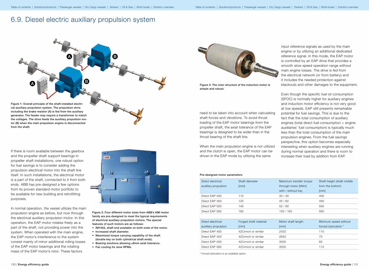
A
A B
B
130 | Energy efficiency guide Energy efficiency guide | 131
If there is room available between the gearbox and the propeller shaft support bearings in propeller shaft installations, one robust option for fuel savings is to consider adding the propulsion electrical motor into the shaft line itself. In such installations, the electrical motor is a part of the shaft, connected to it from both ends. ABB has pre-designed a few options from its proven standard motor portfolio to be available for new building and retrofitting purposes.
In normal operation, the vessel utilizes the main propulsion engine as before, but now through the electrical auxiliary propulsion motor. In this operation, the EAP motor rotates freely as a part of the shaft, not providing power into the system. When operated with the main engine, the EAP motor’s interference to the system consist mainly of minor additional rolling losses of the EAP motor bearings and the rotating mass of the EAP motor’s rotor. These factors
6.9. Diesel electric auxiliary propulsion system
Figure 1: Overall principle of the shaft-installed electri-cal auxiliary propulsion system. The propulsion drive including the brake resistor (A) is fed from the auxiliary generator. The feeder may require a transformer to match the voltages. The drive feeds the auxiliary propulsion mo-tor (B) when the main propulsion engine is disconnected from the shaft.
Figure 2: Four different motor sizes from ABB’s AMI motor family are pre-designed to meet the typical requirements of electrical auxiliary propulsion motors. The special features of such motors are as follows:• IM1002, shaft end available on both ends of the motor.• Increased shaft diameter.• Maximized torque carrying capability of the shaft (double key on both cylindrical shaft ends).• Bearing solutions allowing ±8mm axial tolerance.• Fan cooling for slow RPMs.
need to be taken into account when calculating shaft forces and vibrations. To avoid thrust loading of the EAP motor bearings from the propeller shaft, the axial tolerance of the EAP bearings is designed to be wider than in the thrust bearing of the shaft line. When the main propulsion engine is not utilized and the clutch is open, the EAP motor can be driven in the EAP mode by utilizing the same
input reference signals as used by the main engine or by utilizing an additional dedicated reference signal. In this mode, the EAP motor is controlled by an EAP drive that provides a smooth slow speed operation range without main engine losses. The drive is fed from the electrical network (or from battery) and it includes the needed protection against blackouts and other damages to the equipment.
Even though the specific fuel oil consumption (SFOC) is normally higher for auxiliary engines and induction motor efficiency is not very good at low speeds, EAP still presents remarkable potential for fuel savings. This is due to the fact that the total consumption of auxiliary engines (total direct fuel consumption + engine auxiliaries’ fuel consumption) is typically much less than the total consumption of the main propulsion engines. From the fuel savings perspective, this option becomes especially interesting when auxiliary engines are running during normal operation and there is room to increase their load by addition from EAP.
Figure 3: The rotor structure of the induction motor is simple and robust.
Direct electrical
auxiliary propulsion
Shaft diameter
[mm]
Maximum transfer torque
through motor [kNm]
with / without key
Shaft height (shaft middle
from the bottom)
[mm]
Direct EAP 400 110 30 / 30 400
Direct EAP 450 125 45 / 62 450
Direct EAP 500 140 52 / 90 500
Direct EAP 560 180 105 / 165 560
Direct electrical
auxiliary propulsion
Forged shaft material
[mm]
Motor shaft length
[mm]
Minimum speed without
forced lubrication *
Direct EAP 400 42Crmo4 or similar 2420 110
Direct EAP 450 42Crmo4 or similar 2620 70
Direct EAP 500 42Crmo4 or similar 3000 60
Direct EAP 560 42Crmo4 or similar 3550 110
Pre-designed motor parameters:
* Forced lubrication is an available option
Table of contents | Solutions/products | Passenger vessels | Dry Cargo vessels | Tankers | Oil & Gas | Work boats | Solution overview Table of contents | Solutions/products | Passenger vessels | Dry Cargo vessels | Tankers | Oil & Gas | Work boats | Solution overview

A
B
C
132 | Energy efficiency guide Energy efficiency guide | 133
Motor performance must be evaluated in the speed range defined by the main engine inefficiency. The basic philosophy of auxiliary propulsion is to operate in the propeller speed areas where the use of main propulsion is not efficient.
Above is a table showing motor performances in a 180 rpm situation, which represents an example operation point of 5-6 knots. Each
evaluation should include the estimation of the needed propeller speed in the target slow speed operation of the vessel. Theoretically, the auxiliary propulsion motor efficiency improves while the motor speed increases, and therefore it is recommended that the propeller pitch/power curve is re-designed for the EAP mode taking into account also the propeller and propulsion efficiencies.
Direct electrical
auxiliary propulsion
Available power in
180 RPM / 660 VAC [kW]
Torque rating of motor
[kNm]
Motor efficiency at 180 RPM
[%]
Direct EAP 400 110 5.8 87.8**
Direct EAP 450 230 12.1 88.7**
Direct EAP 500 350 18.5 91.7**
Direct EAP 560 420 32.8 90.7**
** Guidance value. To be verified for each supply individually.
Figure 4: Overall principle of the gear-installed electri-cal auxiliary propulsion system. The propulsion drive including the brake resistor (C) is fed from the auxiliary generator. The drive feeds the auxiliary propulsion motor (B) when the main propulsion engine is clutched from the shaft. The gear ratio of the reduction gear (A) allows for smaller and lighter motor sizes than possible in direct installations.
More power may be taken from the motor by increasing the revolutions. This results in more current via the supplying drive and the motor winding. Therefore, the EAP drive selection should mainly be made based on the current rating of the motor.
The EAP drive, which is a standard ABB ACS800 low voltage drive, needs to be equipped with special software that is suitable for EAP use or with a propulsion control unit for more complex installations. The drive technology is selected according to the network parameters:• either with diode supply and brake resistor,
when network braking of regenerative is not chosen due to low network load and harmonics are tolerated / filtering is possible
• or with low harmonics active front-end and feed transformer (this transformer is always needed for high frequency interference isolation)
High speed electrical auxiliary propulsionWhen the size and weight of the installation are critical design factors, electrical auxiliary propulsion can be implemented with a high-speed induction motor that is connected to the reduction gear (in case there is an input possibility).
In small vessels where geared electrical auxiliary propulsion is often the only possibility for efficiency updates, the most demanding design challenge is typically the auxiliary power source. If there is room for a new power source to be installed and its weight is tolerated, high speed EAP components are often easier to fit in.
In normal operation, the vessel utilizes the main propulsion engine as before. In this operation, the EAP motor, which is a standard ABB motor, rotates freely as a part of the shaft, not providing power into the system. When
operated with the main engine, the EAP motor’s interference to the system consists mainly of minor additional gear and rolling losses. Also the EAP motor’s weight and vibrations need to be taken into account when designing the system update. To minimize mechanical stress to the system, the first option is to consider installation where the motor is flange-connected to the gear and supported from the motor foot. The code for this type of installation is IM2001, but evaluation of the installation also requires support from the gear manufacturers who are the experts with their own designs. When the main propulsion engine is not utilized and the clutch is open, the EAP motor can be driven. The same input reference signals as used by the main engine or an additional dedicated reference signal can be used. In this mode, the EAP motor is controlled by the EAP drive, which provides a smooth slow-speed operation range without main engine losses. The drive is fed from the electrical network (or from battery) and it includes the needed protection against blackouts and other damages to the equipment.
Even though the specific fuel oil consumption (SFOC) is normally higher for auxiliary engines, EAP still presents remarkable potential for fuel savings and plenty of comfort benefits. The slow speed solution greatly improves the induction motor efficiency and often covers also additional gear losses. The fact that the total consumption of auxiliary engines (total direct fuel consumption + engine auxiliaries’ fuel consumption) is typically much less than the total consumption of the main propulsion engines makes the EAP saving potential interesting.
Table of contents | Solutions/products | Passenger vessels | Dry Cargo vessels | Tankers | Oil & Gas | Work boats | Solution overview Table of contents | Solutions/products | Passenger vessels | Dry Cargo vessels | Tankers | Oil & Gas | Work boats | Solution overview
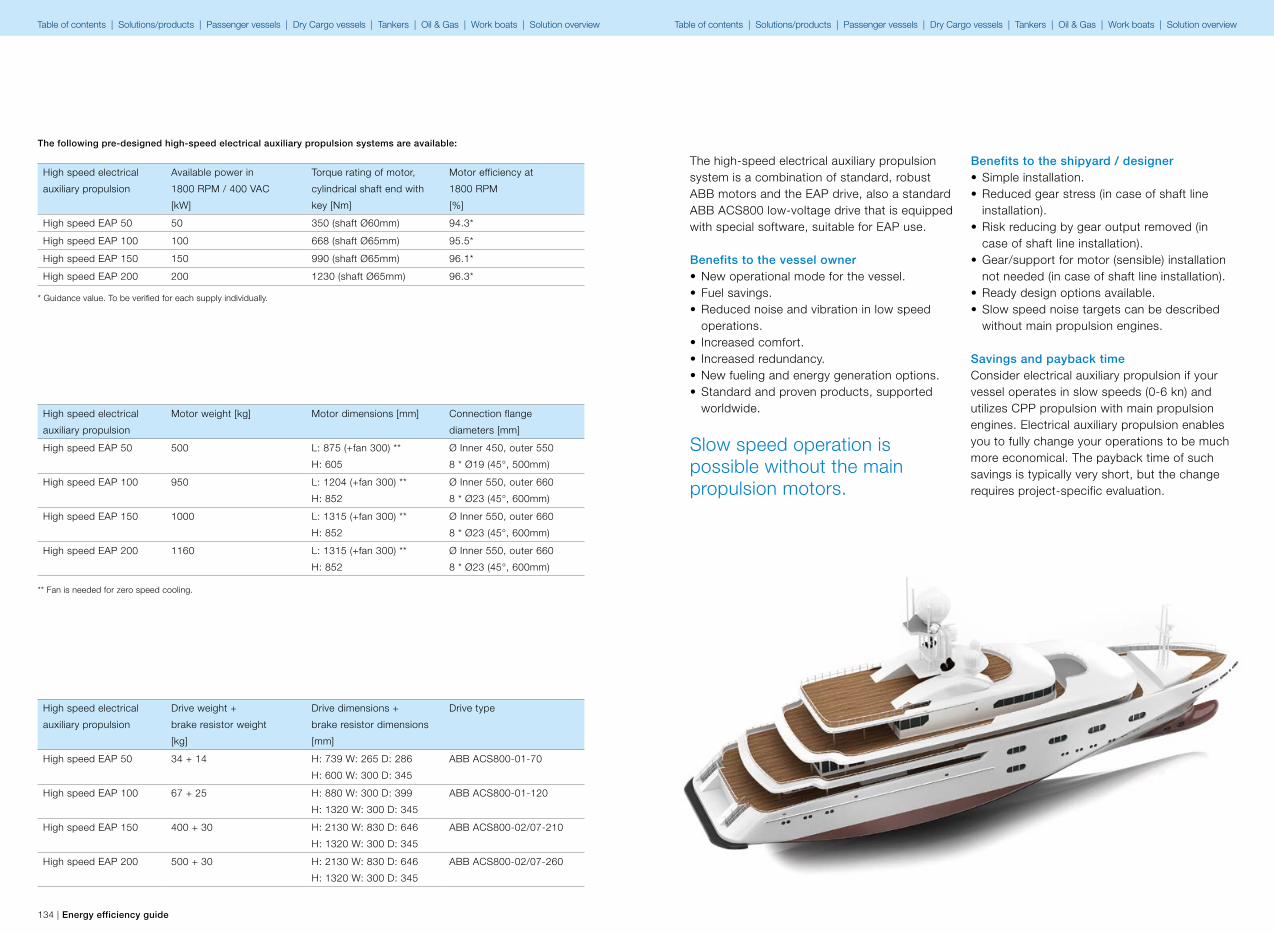
134 | Energy efficiency guide Energy efficiency guide | 135
High speed electrical
auxiliary propulsion
Available power in
1800 RPM / 400 VAC
[kW]
Torque rating of motor,
cylindrical shaft end with
key [Nm]
Motor efficiency at
1800 RPM
[%]
High speed EAP 50 50 350 (shaft Ø60mm) 94.3*
High speed EAP 100 100 668 (shaft Ø65mm) 95.5*
High speed EAP 150 150 990 (shaft Ø65mm) 96.1*
High speed EAP 200 200 1230 (shaft Ø65mm) 96.3*
The following pre-designed high-speed electrical auxiliary propulsion systems are available:
* Guidance value. To be verified for each supply individually.
High speed electrical
auxiliary propulsion
Motor weight [kg] Motor dimensions [mm] Connection flange
diameters [mm]
High speed EAP 50 500 L: 875 (+fan 300) **
H: 605
Ø Inner 450, outer 550
8 * Ø19 (45°, 500mm)
High speed EAP 100 950 L: 1204 (+fan 300) **
H: 852
Ø Inner 550, outer 660
8 * Ø23 (45°, 600mm)
High speed EAP 150 1000 L: 1315 (+fan 300) **
H: 852
Ø Inner 550, outer 660
8 * Ø23 (45°, 600mm)
High speed EAP 200 1160 L: 1315 (+fan 300) **
H: 852
Ø Inner 550, outer 660
8 * Ø23 (45°, 600mm)
High speed electrical
auxiliary propulsion
Drive weight +
brake resistor weight
[kg]
Drive dimensions +
brake resistor dimensions
[mm]
Drive type
High speed EAP 50 34 + 14 H: 739 W: 265 D: 286
H: 600 W: 300 D: 345
ABB ACS800-01-70
High speed EAP 100 67 + 25 H: 880 W: 300 D: 399
H: 1320 W: 300 D: 345
ABB ACS800-01-120
High speed EAP 150 400 + 30 H: 2130 W: 830 D: 646
H: 1320 W: 300 D: 345
ABB ACS800-02/07-210
High speed EAP 200 500 + 30 H: 2130 W: 830 D: 646
H: 1320 W: 300 D: 345
ABB ACS800-02/07-260
** Fan is needed for zero speed cooling.
The high-speed electrical auxiliary propulsion system is a combination of standard, robust ABB motors and the EAP drive, also a standard ABB ACS800 low-voltage drive that is equipped with special software, suitable for EAP use.
Benefits to the vessel owner• New operational mode for the vessel.• Fuel savings.• Reduced noise and vibration in low speed
operations.• Increased comfort.• Increased redundancy.• New fueling and energy generation options.• Standard and proven products, supported
worldwide.
Benefits to the shipyard / designer• Simple installation.• Reduced gear stress (in case of shaft line
installation).• Risk reducing by gear output removed (in
case of shaft line installation).• Gear/support for motor (sensible) installation
not needed (in case of shaft line installation).• Ready design options available.• Slow speed noise targets can be described
without main propulsion engines.
Savings and payback timeConsider electrical auxiliary propulsion if your vessel operates in slow speeds (0-6 kn) and utilizes CPP propulsion with main propulsion engines. Electrical auxiliary propulsion enables you to fully change your operations to be much more economical. The payback time of such savings is typically very short, but the change requires project-specific evaluation.
Slow speed operation is possible without the main propulsion motors.
Table of contents | Solutions/products | Passenger vessels | Dry Cargo vessels | Tankers | Oil & Gas | Work boats | Solution overview Table of contents | Solutions/products | Passenger vessels | Dry Cargo vessels | Tankers | Oil & Gas | Work boats | Solution overview
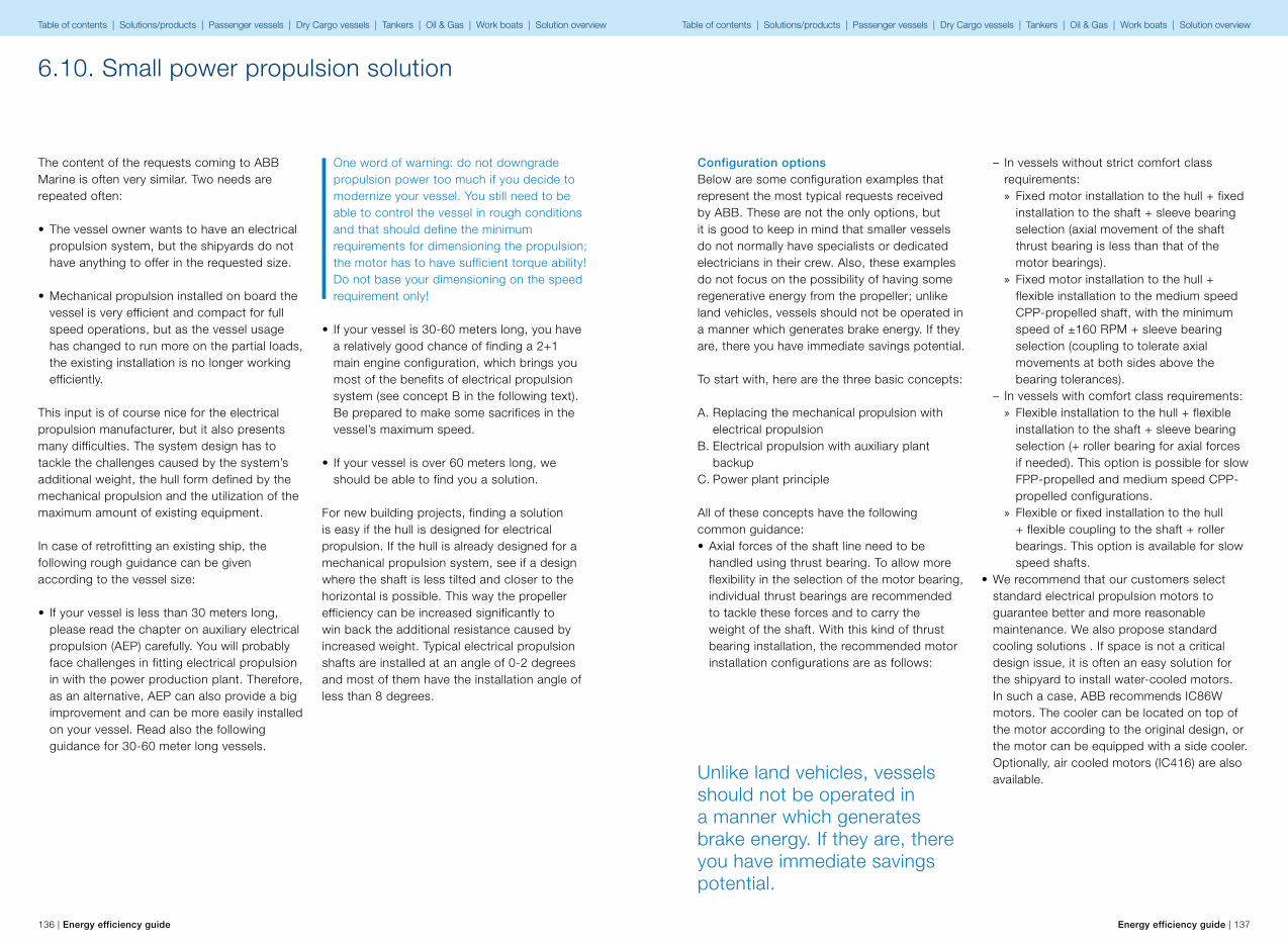
136 | Energy efficiency guide Energy efficiency guide | 137
The content of the requests coming to ABB Marine is often very similar. Two needs are repeated often:
• The vessel owner wants to have an electrical propulsion system, but the shipyards do not have anything to offer in the requested size.
• Mechanical propulsion installed on board the vessel is very efficient and compact for full speed operations, but as the vessel usage has changed to run more on the partial loads, the existing installation is no longer working efficiently.
This input is of course nice for the electrical propulsion manufacturer, but it also presents many difficulties. The system design has to tackle the challenges caused by the system’s additional weight, the hull form defined by the mechanical propulsion and the utilization of the maximum amount of existing equipment.
In case of retrofitting an existing ship, the following rough guidance can be given according to the vessel size:
• If your vessel is less than 30 meters long, please read the chapter on auxiliary electrical propulsion (AEP) carefully. You will probably face challenges in fitting electrical propulsion in with the power production plant. Therefore, as an alternative, AEP can also provide a big improvement and can be more easily installed on your vessel. Read also the following guidance for 30-60 meter long vessels.
One word of warning: do not downgrade propulsion power too much if you decide to modernize your vessel. You still need to be able to control the vessel in rough conditions and that should define the minimum requirements for dimensioning the propulsion; the motor has to have sufficient torque ability! Do not base your dimensioning on the speed requirement only!
• If your vessel is 30-60 meters long, you have a relatively good chance of finding a 2+1 main engine configuration, which brings you most of the benefits of electrical propulsion system (see concept B in the following text). Be prepared to make some sacrifices in the vessel’s maximum speed.
• If your vessel is over 60 meters long, we should be able to find you a solution.
For new building projects, finding a solution is easy if the hull is designed for electrical propulsion. If the hull is already designed for a mechanical propulsion system, see if a design where the shaft is less tilted and closer to the horizontal is possible. This way the propeller efficiency can be increased significantly to win back the additional resistance caused by increased weight. Typical electrical propulsion shafts are installed at an angle of 0-2 degrees and most of them have the installation angle of less than 8 degrees.
6.10. Small power propulsion solution
Configuration optionsBelow are some configuration examples that represent the most typical requests received by ABB. These are not the only options, but it is good to keep in mind that smaller vessels do not normally have specialists or dedicated electricians in their crew. Also, these examples do not focus on the possibility of having some regenerative energy from the propeller; unlike land vehicles, vessels should not be operated in a manner which generates brake energy. If they are, there you have immediate savings potential.
To start with, here are the three basic concepts:
A. Replacing the mechanical propulsion with electrical propulsionB. Electrical propulsion with auxiliary plant backupC. Power plant principle
All of these concepts have the following common guidance:• Axial forces of the shaft line need to be
handled using thrust bearing. To allow more flexibility in the selection of the motor bearing, individual thrust bearings are recommended to tackle these forces and to carry the weight of the shaft. With this kind of thrust bearing installation, the recommended motor installation configurations are as follows:
Unlike land vehicles, vessels should not be operated in a manner which generates brake energy. If they are, there you have immediate savings potential.
– In vessels without strict comfort class requirements: » Fixed motor installation to the hull + fixed installation to the shaft + sleeve bearing selection (axial movement of the shaft thrust bearing is less than that of the motor bearings).
» Fixed motor installation to the hull + flexible installation to the medium speed CPP-propelled shaft, with the minimum speed of ±160 RPM + sleeve bearing selection (coupling to tolerate axial movements at both sides above the bearing tolerances).
– In vessels with comfort class requirements: » Flexible installation to the hull + flexible installation to the shaft + sleeve bearing selection (+ roller bearing for axial forces if needed). This option is possible for slow FPP-propelled and medium speed CPP-propelled configurations.
» Flexible or fixed installation to the hull + flexible coupling to the shaft + roller bearings. This option is available for slow speed shafts.
• We recommend that our customers select standard electrical propulsion motors to guarantee better and more reasonable maintenance. We also propose standard cooling solutions . If space is not a critical design issue, it is often an easy solution for the shipyard to install water-cooled motors. In such a case, ABB recommends IC86W motors. The cooler can be located on top of the motor according to the original design, or the motor can be equipped with a side cooler. Optionally, air cooled motors (IC416) are also available.
Table of contents | Solutions/products | Passenger vessels | Dry Cargo vessels | Tankers | Oil & Gas | Work boats | Solution overview Table of contents | Solutions/products | Passenger vessels | Dry Cargo vessels | Tankers | Oil & Gas | Work boats | Solution overview
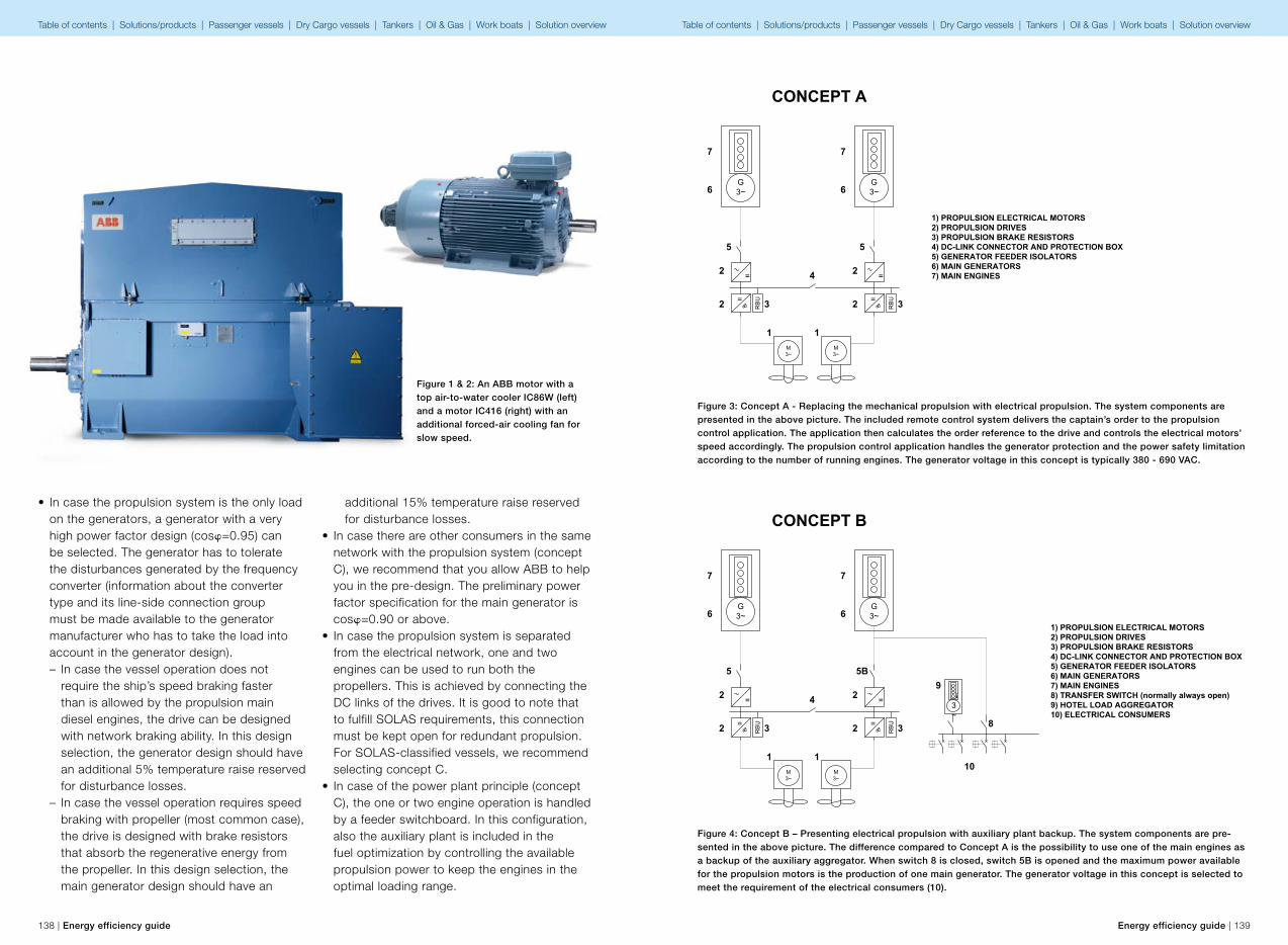
=
=
RB
U =
=
RB
U
M3~
M3~
G3~
G3~
CONCEPT A
1) PROPULSION ELECTRICAL MOTORS2) PROPULSION DRIVES3) PROPULSION BRAKE RESISTORS4) DC-LINK CONNECTOR AND PROTECTION BOX5) GENERATOR FEEDER ISOLATORS6) MAIN GENERATORS7) MAIN ENGINES
11
22
2 2 33
4
5 5
66
77
=
=
RB
U =
=
RB
U
M3~
M3~
G3~
G3~
CONCEPT B
1) PROPULSION ELECTRICAL MOTORS2) PROPULSION DRIVES3) PROPULSION BRAKE RESISTORS4) DC-LINK CONNECTOR AND PROTECTION BOX5) GENERATOR FEEDER ISOLATORS6) MAIN GENERATORS7) MAIN ENGINES8) TRANSFER SWITCH (normally always open)9) HOTEL LOAD AGGREGATOR10) ELECTRICAL CONSUMERS
11
22
2 2 33
4
5 5B
66
77
G3~
8
9
10
138 | Energy efficiency guide Energy efficiency guide | 139
• In case the propulsion system is the only load on the generators, a generator with a very high power factor design (cosφ=0.95) can be selected. The generator has to tolerate the disturbances generated by the frequency converter (information about the converter type and its line-side connection group must be made available to the generator manufacturer who has to take the load into account in the generator design). – In case the vessel operation does not require the ship’s speed braking faster than is allowed by the propulsion main diesel engines, the drive can be designed with network braking ability. In this design selection, the generator design should have an additional 5% temperature raise reserved for disturbance losses.
– In case the vessel operation requires speed braking with propeller (most common case), the drive is designed with brake resistors that absorb the regenerative energy from the propeller. In this design selection, the main generator design should have an
additional 15% temperature raise reserved for disturbance losses.
• In case there are other consumers in the same network with the propulsion system (concept C), we recommend that you allow ABB to help you in the pre-design. The preliminary power factor specification for the main generator is cosφ=0.90 or above.
• In case the propulsion system is separated from the electrical network, one and two engines can be used to run both the propellers. This is achieved by connecting the DC links of the drives. It is good to note that to fulfill SOLAS requirements, this connection must be kept open for redundant propulsion. For SOLAS-classified vessels, we recommend selecting concept C.
• In case of the power plant principle (concept C), the one or two engine operation is handled by a feeder switchboard. In this configuration, also the auxiliary plant is included in the fuel optimization by controlling the available propulsion power to keep the engines in the optimal loading range.
Figure 1 & 2: An ABB motor with a top air-to-water cooler IC86W (left) and a motor IC416 (right) with an additional forced-air cooling fan for slow speed.
Figure 3: Concept A - Replacing the mechanical propulsion with electrical propulsion. The system components are presented in the above picture. The included remote control system delivers the captain’s order to the propulsion control application. The application then calculates the order reference to the drive and controls the electrical motors’ speed accordingly. The propulsion control application handles the generator protection and the power safety limitation according to the number of running engines. The generator voltage in this concept is typically 380 - 690 VAC.
Figure 4: Concept B – Presenting electrical propulsion with auxiliary plant backup. The system components are pre-sented in the above picture. The difference compared to Concept A is the possibility to use one of the main engines as a backup of the auxiliary aggregator. When switch 8 is closed, switch 5B is opened and the maximum power available for the propulsion motors is the production of one main generator. The generator voltage in this concept is selected to meet the requirement of the electrical consumers (10).
Table of contents | Solutions/products | Passenger vessels | Dry Cargo vessels | Tankers | Oil & Gas | Work boats | Solution overview Table of contents | Solutions/products | Passenger vessels | Dry Cargo vessels | Tankers | Oil & Gas | Work boats | Solution overview
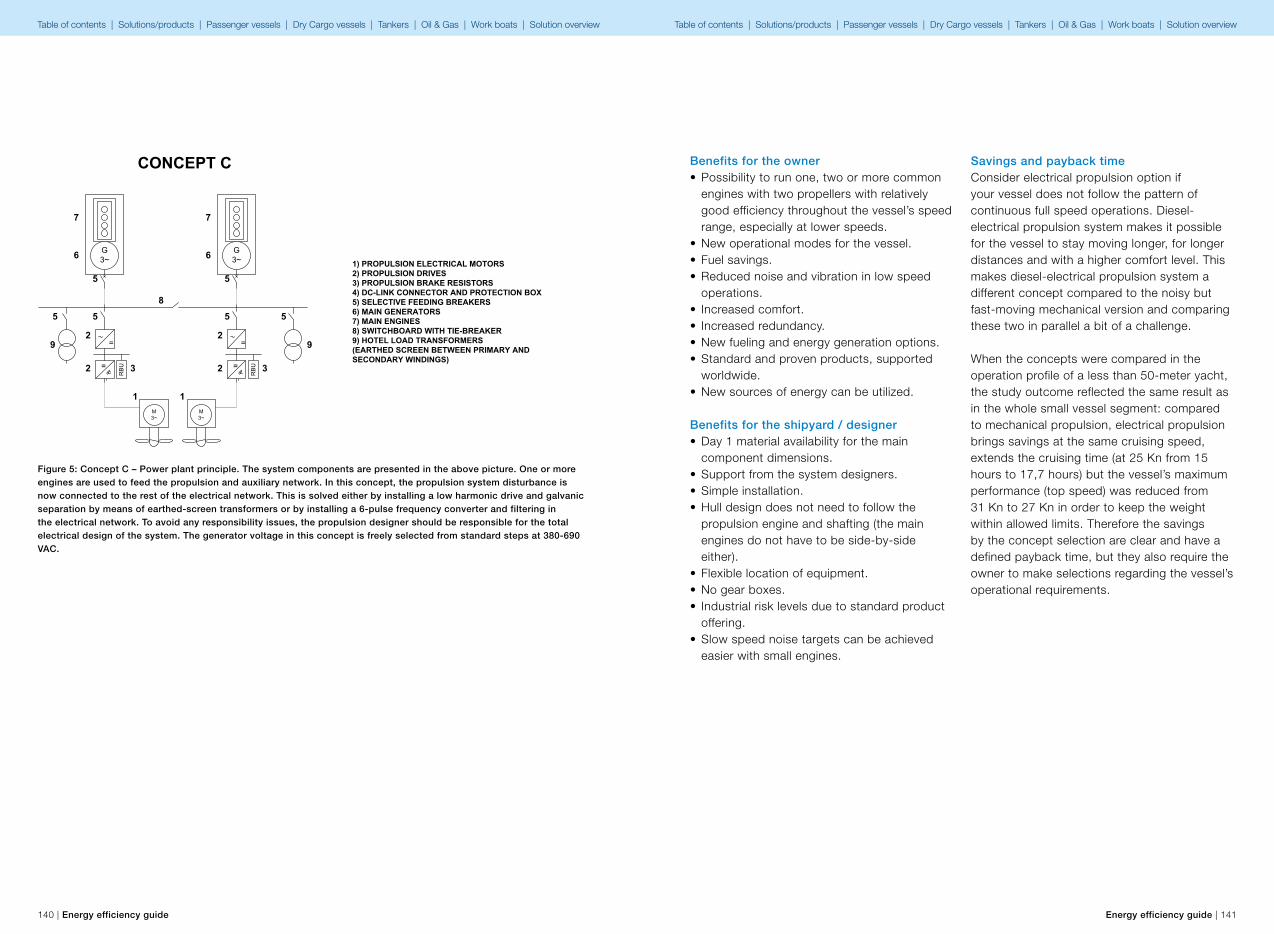
M3~
M3~
CONCEPT C
1) PROPULSION ELECTRICAL MOTORS2) PROPULSION DRIVES3) PROPULSION BRAKE RESISTORS4) DC-LINK CONNECTOR AND PROTECTION BOX5) SELECTIVE FEEDING BREAKERS6) MAIN GENERATORS7) MAIN ENGINES8) SWITCHBOARD WITH TIE-BREAKER9) HOTEL LOAD TRANSFORMERS (EARTHED SCREEN BETWEEN PRIMARY AND SECONDARY WINDINGS)
11
22
2 2 33
5 5
66
77
=
=
RB
U =
=
RB
UG3~
G3~
5 5
8
99
55
140 | Energy efficiency guide Energy efficiency guide | 141
Figure 5: Concept C – Power plant principle. The system components are presented in the above picture. One or more engines are used to feed the propulsion and auxiliary network. In this concept, the propulsion system disturbance is now connected to the rest of the electrical network. This is solved either by installing a low harmonic drive and galvanic separation by means of earthed-screen transformers or by installing a 6-pulse frequency converter and filtering in the electrical network. To avoid any responsibility issues, the propulsion designer should be responsible for the total electrical design of the system. The generator voltage in this concept is freely selected from standard steps at 380-690 VAC.
Benefits for the owner• Possibility to run one, two or more common
engines with two propellers with relatively good efficiency throughout the vessel’s speed range, especially at lower speeds.
• New operational modes for the vessel.• Fuel savings.• Reduced noise and vibration in low speed
operations.• Increased comfort.• Increased redundancy.• New fueling and energy generation options.• Standard and proven products, supported
worldwide.• New sources of energy can be utilized.
Benefits for the shipyard / designer• Day 1 material availability for the main
component dimensions.• Support from the system designers.• Simple installation.• Hull design does not need to follow the
propulsion engine and shafting (the main engines do not have to be side-by-side either).
• Flexible location of equipment.• No gear boxes.• Industrial risk levels due to standard product
offering.• Slow speed noise targets can be achieved
easier with small engines.
Savings and payback timeConsider electrical propulsion option if your vessel does not follow the pattern of continuous full speed operations. Diesel-electrical propulsion system makes it possible for the vessel to stay moving longer, for longer distances and with a higher comfort level. This makes diesel-electrical propulsion system a different concept compared to the noisy but fast-moving mechanical version and comparing these two in parallel a bit of a challenge.
When the concepts were compared in the operation profile of a less than 50-meter yacht, the study outcome reflected the same result as in the whole small vessel segment: compared to mechanical propulsion, electrical propulsion brings savings at the same cruising speed, extends the cruising time (at 25 Kn from 15 hours to 17,7 hours) but the vessel’s maximum performance (top speed) was reduced from 31 Kn to 27 Kn in order to keep the weight within allowed limits. Therefore the savings by the concept selection are clear and have a defined payback time, but they also require the owner to make selections regarding the vessel’s operational requirements.
Table of contents | Solutions/products | Passenger vessels | Dry Cargo vessels | Tankers | Oil & Gas | Work boats | Solution overview Table of contents | Solutions/products | Passenger vessels | Dry Cargo vessels | Tankers | Oil & Gas | Work boats | Solution overview

142 | Energy efficiency guide Energy efficiency guide | 143
6.11. Azipod® propulsion
Efficiency and availabilityAzipod technology was introduced in 1990. The first cruise vessel installation on the Fantasy-class vessel Elation in 1998 showed remarkably positive results with high efficiency and excellent maneuverability. The new technology provided ship designers with greater freedom to optimize the ship’s general arrangement.
After processing further knowledge from experience and getting a better understanding of the system’s behavior in operation, the scope of development was widened to cover larger systems.
Design improvementsAt first the improvements were mainly concentrated on shaft bearings and seals. While the basic mechanical design remained the same, the focus was to provide improved lubrication conditions and to improve seals to prevent any leakages into the lube oil or into the sea.
After collecting several years of operational experience with wider knowledge of system behavior, improvements were broadened to include processes like better control of manufacturing, delivery and operational processes, and general quality control.
Time for redesignAfter several generations of updates from the original design, it was seen that a concurrent redesign would be necessary to be able to combine all identified improvement ideas. The first such development project addressed the larger open water unit series, which was subsequently given the identifying type code Azipod XO where X stands for “next generation Azipod” and O means that it is mainly made for vessels that will operate in open water conditions. In this research and development project ABB Marine decided to utilize well-
known, proven technologies for components and design. As an example of the latter, sliding bearings were selected for thrust bearings.
The outer shaft seal was also completely redesigned to provide similar benefits: reliability and maintainability. The seal system enables advanced condition monitoring to a degree not seen elsewhere in the market.
For larger models the seal can be changed from inside the pod. The seal is designed for a five-year lifetime and to be replaced during normal dry-dockings, but in case of an emergency situation this can also be done with the vessel afloat.
The fully electric steering gear was originally designed for smaller Azipod sizes, but it was the right time to introduce it for larger open water unit sizes to replace conventional electro-hydraulic steering gear. The main reasons for this step were that it reduced energy consumption and noise, as well as cutting the amount of oil in the installation, in order to make it more environmentally friendly. Electric steering gear is now installed on recent Azipod deliveries for open water conditions.
Figure 1: Azipod operating hours and on duty percentage
2000
2001
2002
2003
2004
2005
2006
2007
2008
2009
2010
2011
2012
0 99.2%
99.3%
99.4%
99.5%
99.6%
99.7%
99.8%
99.9%
100.0%
1,000,000
2,000,000
3,000,000
4,000,000
5,000,000
7,000,000
6,000,000
8,000,000
Azipod operating hours and on duty percentage
On duty %Oper hours
Improved fuel efficiencyThe propulsion efficiency of Azipod propulsion, when originally installed on cruise ship Elation back in 1997, improved by some 9 percent, when comparing identical sisterships with traditional shaftlines. Since then, the propulsion efficiency has been improved by several steps in design optimization (Figure 2).
One major hydrodynamic improvement was gained early by installing a fin under the Azipod to reduce rotational flow losses generated by the propeller. In the next steps, the Azipod strut design was modified by making it slimmer and more optimal for operation in the propulsion environment. Finally, with the Azipod XO, the propeller hub and motor module diameters were reduced and the unIt is entire hull was optimized with the help of CFD and model testing.
During 2011, ABB introduced an additional package to improve Azipod propulsion efficiency
further. This package consists of an asymmetric lower fin and crossed plates (X-tail) that are integrated in the aft cone. The asymmetric lower fin will improve efficiency up to 1 percent by reducing the losses from the propulsion system and the X-tail will further increase efficiency by up to 1.5 percent by reducing the rotational flow losses at the aft cone section. These changes can also be made as a retrofit installation on open water units. The first retrofit work with asymmetric fin and X-tail was done in 2011 during the vessel’s normal dry docking.
Also in 2011, ABB launched a method of optimizing the energy efficiency of Azipod installations on board vessels. This was based on the finding that further fuel consumption savings can be reached by optimizing the toe (steering) angle of the Azipod units dynamically, in addition to the angle optimization already undertaken at the vessel design stage. This package has the acronym ADO from the words
Figure 2: Propulsion efficiency has been improvedby several steps in design optimization
7.5% − 9%
> 9%
> 20%
Fantasy class diesel electric conventional shaftline propulsion system
First cruise linersElation, Paradise
New profile on strutand fin on last vessels ofVoyager Class
Added finRadiance Class
New profile and geometryoptimisation for Solsticeand Genesis Class
Azipod XO
Latest developments
First generation Azipod propulsion
1997 1999 2001 2005 2009 2012
Table of contents | Solutions/products | Passenger vessels | Dry Cargo vessels | Tankers | Oil & Gas | Work boats | Solution overview Table of contents | Solutions/products | Passenger vessels | Dry Cargo vessels | Tankers | Oil & Gas | Work boats | Solution overview

144 | Energy efficiency guide Energy efficiency guide | 145
“Azipod Dynamic Optimizer”. Fuel consumption is estimated to be reduced further by up to 1.5 percent using ADO.
The overall improvement in propulsion efficiency has been above 10 percent over the course of the existence of the Azipod, with a more than 20 percent gain when compared to the shaftlines being used back in the mid 1990s. However, it is fair to acknowledge that there have also been improvements in shaftline propulsion during this time. Even so, a recent comparison test at
The propulsion motor technology in Azipod units is selected so that it will achieve high efficiency throughout the entire propeller speed range.
Marin showed that Azipod propulsion compared to a fixed shaftline propulsion design still had a 6-8 percent lead what regards to propulsion efficiency. Furthermore, these tests were made before the introduction of asymmetric fin, X-tail and ADO, which can improve the efficiency of the Azipod system overall by up to four percent.
Operation experienceWith regards to fuel savings and ship maneuverability, the expectations set by ship operators have typically been fulfilled or exceeded by the Azipod. Ship captains in particular have expressed satisfaction with the ease of operation and the maneuverability of their ships. Concerning energy efficiency, some operators have claimed fuel savings of more than 20 percent, compared with their vessels operating with conventional propulsion.
Seven million operating hours with Azipod propulsion have resulted in the largest pool of experience in how podded propulsion systems should be designed, used and maintained for trouble-free reliable operation.
During the two decades ABB has established a unique position being the only company that has in-depth and in-house product and integration knowledge, with a responsibility covering the whole concept from hydrodynamics, mechanics, electronics, cooling to operating, maintenance and services, as well as the integration of the complete electrical and control system.
The advantage of having data available from a large number of operating units as well as a wide range of test results from models and full size units has been essential for continuous development.
Nowadays, Azipod propulsion and thruster units are designed for five years dry-docking and maintenance intervals. For some applications a longer maintenance interval of even up to 10 years has proven supportable. This conclusion is based on results drawn from a well documented operational and maintenance history. Today, there are some 100 vessels using Azipod propulsion. It has been selected for a wide range of ship types and operations; such as cruise ships, icebreakers and ice-going cargo vessels, ferries, megayachts, offshore supply vessels, research vessels, wind turbine installation vessels and drilling rigs.
Table of contents | Solutions/products | Passenger vessels | Dry Cargo vessels | Tankers | Oil & Gas | Work boats | Solution overview Table of contents | Solutions/products | Passenger vessels | Dry Cargo vessels | Tankers | Oil & Gas | Work boats | Solution overview
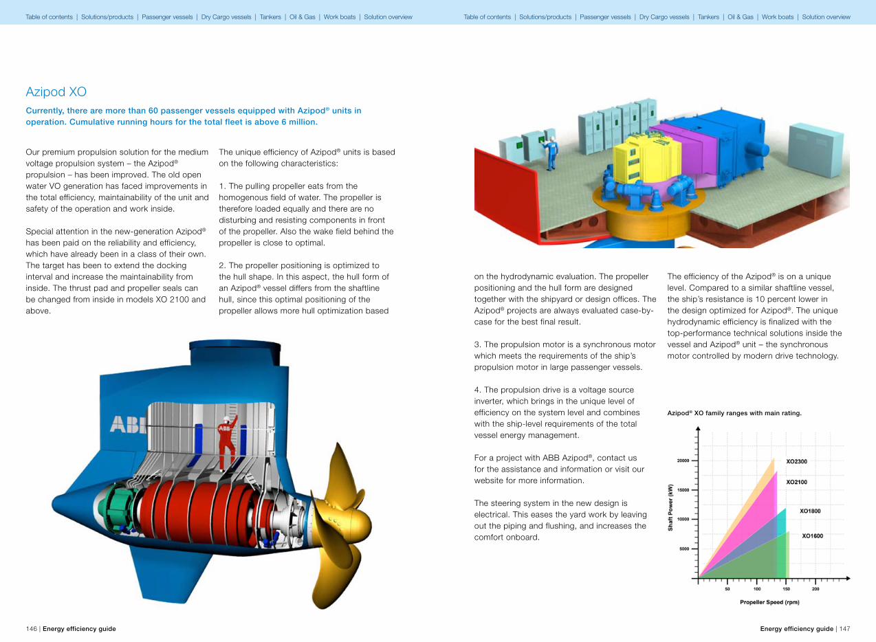
146 | Energy efficiency guide Energy efficiency guide | 147
Azipod XOCurrently, there are more than 60 passenger vessels equipped with Azipod® units in operation. Cumulative running hours for the total fleet is above 6 million.
Our premium propulsion solution for the medium voltage propulsion system – the Azipod® propulsion – has been improved. The old open water VO generation has faced improvements in the total efficiency, maintainability of the unit and safety of the operation and work inside.
Special attention in the new-generation Azipod® has been paid on the reliability and efficiency, which have already been in a class of their own. The target has been to extend the docking interval and increase the maintainability from inside. The thrust pad and propeller seals can be changed from inside in models XO 2100 and above.
The unique efficiency of Azipod® units is based on the following characteristics:
1. The pulling propeller eats from the homogenous field of water. The propeller is therefore loaded equally and there are no disturbing and resisting components in front of the propeller. Also the wake field behind the propeller is close to optimal.
2. The propeller positioning is optimized to the hull shape. In this aspect, the hull form of an Azipod® vessel differs from the shaftline hull, since this optimal positioning of the propeller allows more hull optimization based
Azipod® XO family ranges with main rating.
on the hydrodynamic evaluation. The propeller positioning and the hull form are designed together with the shipyard or design offices. The Azipod® projects are always evaluated case-by-case for the best final result.
3. The propulsion motor is a synchronous motor which meets the requirements of the ship’s propulsion motor in large passenger vessels.
4. The propulsion drive is a voltage source inverter, which brings in the unique level of efficiency on the system level and combines with the ship-level requirements of the total vessel energy management.
For a project with ABB Azipod®, contact us for the assistance and information or visit our website for more information.
The steering system in the new design is electrical. This eases the yard work by leaving out the piping and flushing, and increases the comfort onboard.
The efficiency of the Azipod® is on a unique level. Compared to a similar shaftline vessel, the ship’s resistance is 10 percent lower in the design optimized for Azipod®. The unique hydrodynamic efficiency is finalized with the top-performance technical solutions inside the vessel and Azipod® unit – the synchronous motor controlled by modern drive technology.
Table of contents | Solutions/products | Passenger vessels | Dry Cargo vessels | Tankers | Oil & Gas | Work boats | Solution overview Table of contents | Solutions/products | Passenger vessels | Dry Cargo vessels | Tankers | Oil & Gas | Work boats | Solution overview
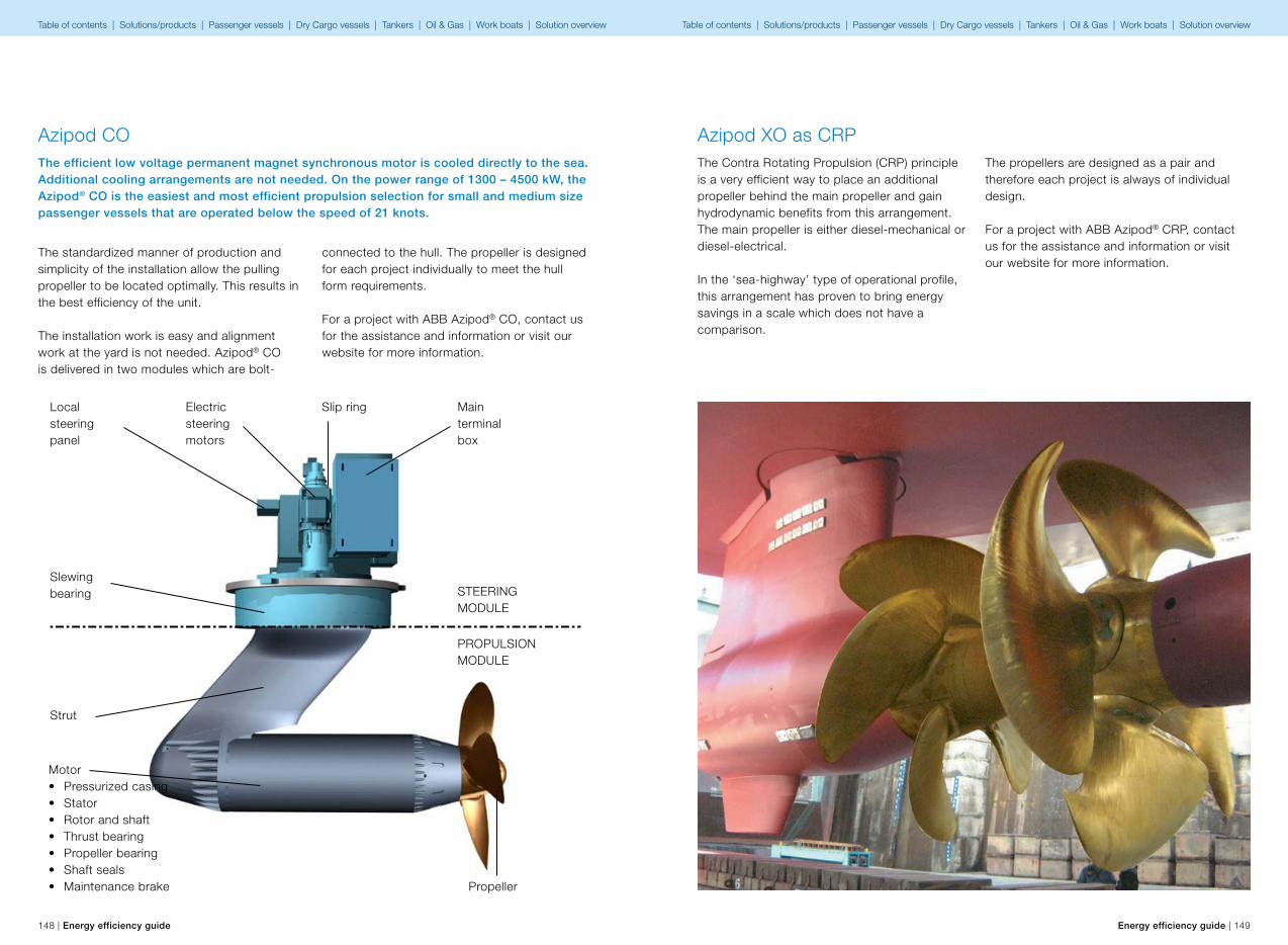
148 | Energy efficiency guide Energy efficiency guide | 149
The efficient low voltage permanent magnet synchronous motor is cooled directly to the sea. Additional cooling arrangements are not needed. On the power range of 1300 – 4500 kW, the Azipod® CO is the easiest and most efficient propulsion selection for small and medium size passenger vessels that are operated below the speed of 21 knots.
Strut
Motor• Pressurized casing• Stator• Rotor and shaft• Thrust bearing• Propeller bearing• Shaft seals• Maintenance brake
Slewing bearing
Slip ring
Propeller
Main terminal box
STEERINGMODULE
PROPULSIONMODULE
Electric steering motors
Local steering panel
The standardized manner of production and simplicity of the installation allow the pulling propeller to be located optimally. This results in the best efficiency of the unit.
The installation work is easy and alignment work at the yard is not needed. Azipod® CO is delivered in two modules which are bolt-
connected to the hull. The propeller is designed for each project individually to meet the hull form requirements.
For a project with ABB Azipod® CO, contact us for the assistance and information or visit our website for more information.
Azipod COThe Contra Rotating Propulsion (CRP) principle is a very efficient way to place an additional propeller behind the main propeller and gain hydrodynamic benefits from this arrangement. The main propeller is either diesel-mechanical or diesel-electrical. In the ‘sea-highway’ type of operational profile, this arrangement has proven to bring energy savings in a scale which does not have a comparison.
The propellers are designed as a pair and therefore each project is always of individual design.
For a project with ABB Azipod® CRP, contact us for the assistance and information or visit our website for more information.
Azipod XO as CRP
Table of contents | Solutions/products | Passenger vessels | Dry Cargo vessels | Tankers | Oil & Gas | Work boats | Solution overview Table of contents | Solutions/products | Passenger vessels | Dry Cargo vessels | Tankers | Oil & Gas | Work boats | Solution overview

Toe angle
150 | Energy efficiency guide Energy efficiency guide | 151
Background of AzipodThe ABB Azipod is an azimuthing electric podded drive used in diesel-electric vessels. The Azipod unit is fixed in a pod outside the ship, and combines the functions of a propulsion motor, main propeller, rudder and stern thruster. This innovation was introduced in 1990, in a pilot installation for a Finnish fairway maintenance vessel, and was later installed in
some ice-going vessels and ice breakers. The first cruise vessel installation was performed in 1998 on a Fantasy-class cruise ship, the “Elation”. Compared to previous Fantasy-class vessels, the “Elation” displayed remarkably positive results, including high efficiency and excellent maneuverability. The technology also provided ship designers with greater freedom to optimize the ship’s general structure.
6.12. Azipod® hydrodynamics upgrade
Figure 1: X-tail and asymmetric fin installed during dry docking in 2011. The tests confirmed a 2.8% improvement in efficiency.
The first Azipod units installed in the “Elation” yielded an approximately 7– 9 percent reduction in the required propulsion power, compared to older Fantasy-class vessels equipped with the more traditional shaftline arrangement. A major hydrodynamic improvement was gained early on, by installing a fin under the Azipod to reduce rotational flow losses generated by the propeller. The lower fin also provided an efficient way of reducing steering system loads, by decreasing the azimuthing counter torque. In the subsequent steps, the Azipod strut design was modified by making it slimmer and more optimal, for operation in a propulsion environment. Finally, with the introduction of the new Azipod XO product family, the propeller hub and motor module diameters were reduced and the entire hull optimized with the help of CFD and model testing. All in all, Azipod hydrodynamic improvements, from the first units to Azipod XO, have represented an improvement of 9 percent on the “Elation” results.
Azipod hydrodynamics upgradeDuring 2011, ABB introduced an additional retrofit package to further improve the Azipod’s propulsion efficiency. This package consists of an asymmetric lower fin and crossed plates (X-tail) integrated with the aft cone.
The asymmetric lower fin improves efficiency up to 1 percent, by reducing losses from the propulsion system, while the X-tail can further increase efficiency by up to 1.5 percent, by lowering the rotational flow losses from the aft cone section. These changes can be performed as a retrofit installation for open water units during dry docking. Due to different design and load conditions, such modifications are not applicable to ice-going vessels.
The total savings potential of the Azipod hydrodynamics upgrade can be up to 4 percent in propulsion power
Figure 2: The optimal toe angle between the Azipod units varies dynamically, depending on the operating condi-tions. The Azipod Dynamic Optimization system has a savings potential of up to 1.5 percent.
Table of contents | Solutions/products | Passenger vessels | Dry Cargo vessels | Tankers | Oil & Gas | Work boats | Solution overview Table of contents | Solutions/products | Passenger vessels | Dry Cargo vessels | Tankers | Oil & Gas | Work boats | Solution overview
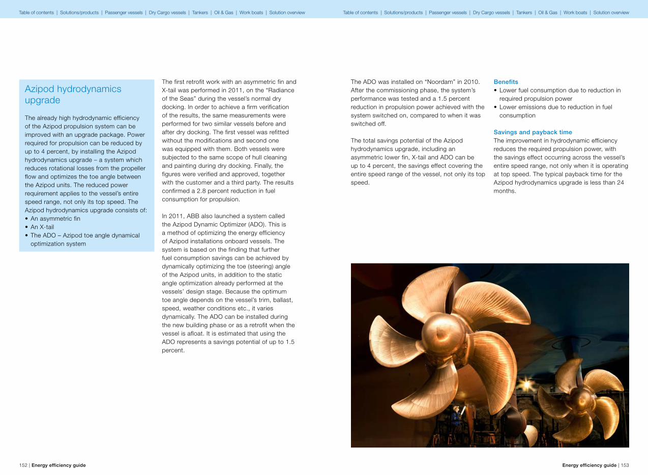
152 | Energy efficiency guide Energy efficiency guide | 153
The first retrofit work with an asymmetric fin and X-tail was performed in 2011, on the “Radiance of the Seas” during the vessel’s normal dry docking. In order to achieve a firm verification of the results, the same measurements were performed for two similar vessels before and after dry docking. The first vessel was refitted without the modifications and second one was equipped with them. Both vessels were subjected to the same scope of hull cleaning and painting during dry docking. Finally, the figures were verified and approved, together with the customer and a third party. The results confirmed a 2.8 percent reduction in fuel consumption for propulsion.
In 2011, ABB also launched a system called the Azipod Dynamic Optimizer (ADO). This is a method of optimizing the energy efficiency of Azipod installations onboard vessels. The system is based on the finding that further fuel consumption savings can be achieved by dynamically optimizing the toe (steering) angle of the Azipod units, in addition to the static angle optimization already performed at the vessels’ design stage. Because the optimum toe angle depends on the vessel’s trim, ballast, speed, weather conditions etc., it varies dynamically. The ADO can be installed during the new building phase or as a retrofit when the vessel is afloat. It is estimated that using the ADO represents a savings potential of up to 1.5 percent.
Azipod hydrodynamics upgrade
The already high hydrodynamic efficiency of the Azipod propulsion system can be improved with an upgrade package. Power required for propulsion can be reduced by up to 4 percent, by installing the Azipod hydrodynamics upgrade – a system which reduces rotational losses from the propeller flow and optimizes the toe angle between the Azipod units. The reduced power requirement applies to the vessel’s entire speed range, not only its top speed. The Azipod hydrodynamics upgrade consists of:• An asymmetric fin• An X-tail• The ADO – Azipod toe angle dynamical
optimization system
The ADO was installed on “Noordam” in 2010. After the commissioning phase, the system’s performance was tested and a 1.5 percent reduction in propulsion power achieved with the system switched on, compared to when it was switched off.
The total savings potential of the Azipod hydrodynamics upgrade, including an asymmetric lower fin, X-tail and ADO can be up to 4 percent, the savings effect covering the entire speed range of the vessel, not only its top speed.
Benefits• Lower fuel consumption due to reduction in
required propulsion power• Lower emissions due to reduction in fuel
consumption
Savings and payback timeThe improvement in hydrodynamic efficiency reduces the required propulsion power, with the savings effect occurring across the vessel’s entire speed range, not only when it is operating at top speed. The typical payback time for the Azipod hydrodynamics upgrade is less than 24 months.
Table of contents | Solutions/products | Passenger vessels | Dry Cargo vessels | Tankers | Oil & Gas | Work boats | Solution overview Table of contents | Solutions/products | Passenger vessels | Dry Cargo vessels | Tankers | Oil & Gas | Work boats | Solution overview
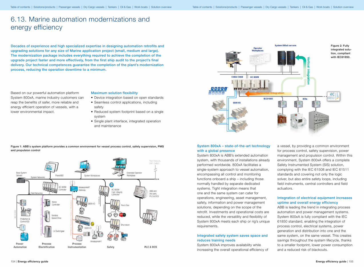
154 | Energy efficiency guide Energy efficiency guide | 155
6.13. Marine automation modernizations and energy efficiency
Decades of experience and high specialized expertise in designing automation retrofits and upgrading solutions for any size of Marine application project (small, medium and large). The modernization package includes everything required to achieve the completion of the upgrade project faster and more effectively, from the first ship audit to the project’s final delivery. Our technical competences guarantee the completion of the plant’s modernization process, reducing the operation downtime to a minimum.
Maximum solution flexibility• Device integration based on open standards• Seamless control applications, including
safety• Reduced system footprint based on a single
system• Single plant interface, integrated operation
and maintenance
Figure 1: ABB´s system platform provides a common environment for vessel process control, safety supervision, PMS and propulsion control
Based on our powerful automation platform System 800xA, marine industry customers can reap the benefits of safer, more reliable and energy efficient operation of vessels, with a lower environmental impact.
System 800xA – state-of-the-art technology with a global presenceSystem 800xA is ABB’s extended automation system, with thousands of installations already performed worldwide. 800xA facilitates a single-system approach to vessel automation, encompassing all control and monitoring functions onboard a ship – including those normally handled by separate dedicated systems. Tight integration means that one and the same system can cater for operations, engineering, asset management, safety, information and power management solutions, depending on the scope of the retrofit. Investments and operational costs are reduced, while the versatility and flexibility of System 800xA meets each ship or rig’s unique requirements.
Integrated safety system saves space and reduces training needsSystem 800xA improves availability while increasing the overall operational efficiency of
a vessel, by providing a common environment for process control, safety supervision, power management and propulsion control. Within this environment, System 800xA offers a complete Safety Instrumented System (SIS) solution, complying with the IEC 61508 and IEC 61511 standards and covering not only the logic solver, but also entire safety loops, including field instruments, central controllers and field actuators.
Integration of electrical equipment increases uptime and overall energy efficiencyABB is leading the trend in integrating process automation and power management systems. System 800xA is fully compliant with the IEC 61850 standard, enabling the integration of process control, electrical systems, power generation and distribution into one and the same system, on the same vessel. This creates savings throughout the system lifecycle, thanks to a smaller footprint, lower power consumption and a reduced risk of blackouts.
Figure 2: Fully integrated solu-tion, compliant with IEC61850.
Table of contents | Solutions/products | Passenger vessels | Dry Cargo vessels | Tankers | Oil & Gas | Work boats | Solution overview Table of contents | Solutions/products | Passenger vessels | Dry Cargo vessels | Tankers | Oil & Gas | Work boats | Solution overview
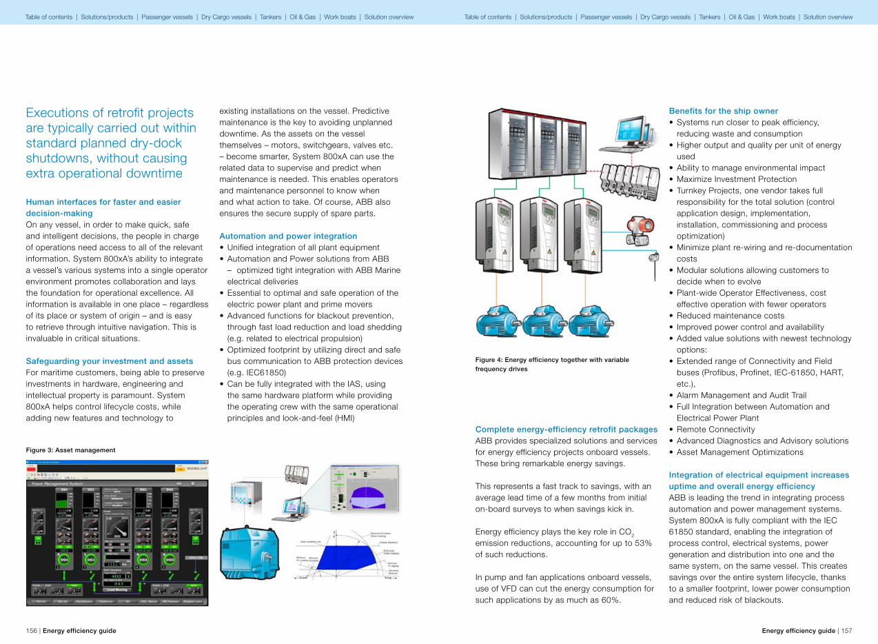
156 | Energy efficiency guide Energy efficiency guide | 157
Human interfaces for faster and easier decision-makingOn any vessel, in order to make quick, safe and intelligent decisions, the people in charge of operations need access to all of the relevant information. System 800xA’s ability to integrate a vessel’s various systems into a single operator environment promotes collaboration and lays the foundation for operational excellence. All information is available in one place – regardless of its place or system of origin – and is easy to retrieve through intuitive navigation. This is invaluable in critical situations.
Safeguarding your investment and assetsFor maritime customers, being able to preserve investments in hardware, engineering and intellectual property is paramount. System 800xA helps control lifecycle costs, while adding new features and technology to
existing installations on the vessel. Predictive maintenance is the key to avoiding unplanned downtime. As the assets on the vessel themselves – motors, switchgears, valves etc. – become smarter, System 800xA can use the related data to supervise and predict when maintenance is needed. This enables operators and maintenance personnel to know when and what action to take. Of course, ABB also ensures the secure supply of spare parts.
Automation and power integration• Unified integration of all plant equipment• Automation and Power solutions from ABB
– optimized tight integration with ABB Marine electrical deliveries
• Essential to optimal and safe operation of the electric power plant and prime movers
• Advanced functions for blackout prevention, through fast load reduction and load shedding (e.g. related to electrical propulsion)
• Optimized footprint by utilizing direct and safe bus communication to ABB protection devices (e.g. IEC61850)
• Can be fully integrated with the IAS, using the same hardware platform while providing the operating crew with the same operational principles and look-and-feel (HMI)
Figure 3: Asset management
Executions of retrofit projects are typically carried out within standard planned dry-dock shutdowns, without causing extra operational downtime
Complete energy-efficiency retrofit packages ABB provides specialized solutions and services for energy efficiency projects onboard vessels. These bring remarkable energy savings.
This represents a fast track to savings, with an average lead time of a few months from initial on-board surveys to when savings kick in.
Energy efficiency plays the key role in CO2 emission reductions, accounting for up to 53% of such reductions.
In pump and fan applications onboard vessels, use of VFD can cut the energy consumption for such applications by as much as 60%.
Benefits for the ship owner• Systems run closer to peak efficiency,
reducing waste and consumption• Higher output and quality per unit of energy
used• Ability to manage environmental impact• Maximize Investment Protection• Turnkey Projects, one vendor takes full
responsibility for the total solution (control application design, implementation, installation, commissioning and process optimization)
• Minimize plant re-wiring and re-documentation costs
• Modular solutions allowing customers to decide when to evolve
• Plant-wide Operator Effectiveness, cost effective operation with fewer operators
• Reduced maintenance costs• Improved power control and availability • Added value solutions with newest technology
options:• Extended range of Connectivity and Field
buses (Profibus, Profinet, IEC-61850, HART, etc.),
• Alarm Management and Audit Trail• Full Integration between Automation and
Electrical Power Plant• Remote Connectivity• Advanced Diagnostics and Advisory solutions• Asset Management Optimizations
Integration of electrical equipment increases uptime and overall energy efficiencyABB is leading the trend in integrating process automation and power management systems. System 800xA is fully compliant with the IEC 61850 standard, enabling the integration of process control, electrical systems, power generation and distribution into one and the same system, on the same vessel. This creates savings over the entire system lifecycle, thanks to a smaller footprint, lower power consumption and reduced risk of blackouts.
Figure 4: Energy efficiency together with variable frequency drives
Table of contents | Solutions/products | Passenger vessels | Dry Cargo vessels | Tankers | Oil & Gas | Work boats | Solution overview Table of contents | Solutions/products | Passenger vessels | Dry Cargo vessels | Tankers | Oil & Gas | Work boats | Solution overview
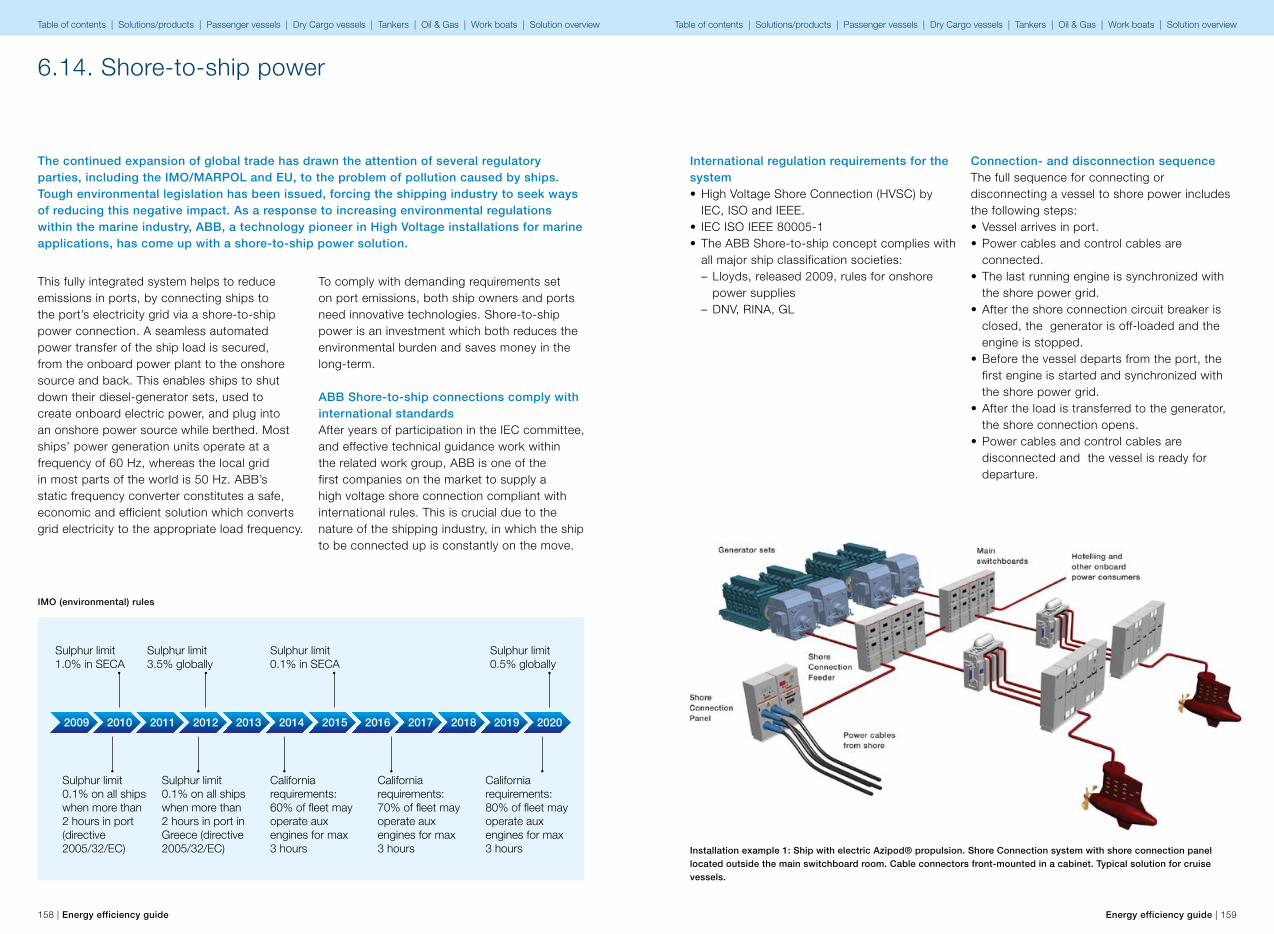
2009 2010
Sulphur limit 0.1% on all ships when more than 2 hours in port (directive 2005/32/EC)
Sulphur limit 1.0% in SECA
2011 2012 2013 2014 2015 2016 2017 2018 2019 2020
Sulphur limit 0.1% on all ships when more than 2 hours in port in Greece (directive 2005/32/EC)
California requirements: 60% of �eet may operate aux engines for max 3 hours
California requirements: 70% of �eet may operate aux engines for max 3 hours
California requirements: 80% of �eet may operate aux engines for max 3 hours
Sulphur limit 0.1% in SECA
Sulphur limit 3.5% globally
Sulphur limit 0.5% globally
158 | Energy efficiency guide Energy efficiency guide | 159
The continued expansion of global trade has drawn the attention of several regulatory parties, including the IMO/MARPOL and EU, to the problem of pollution caused by ships. Tough environmental legislation has been issued, forcing the shipping industry to seek ways of reducing this negative impact. As a response to increasing environmental regulations within the marine industry, ABB, a technology pioneer in High Voltage installations for marine applications, has come up with a shore-to-ship power solution.
6.14. Shore-to-ship power
To comply with demanding requirements set on port emissions, both ship owners and ports need innovative technologies. Shore-to-ship power is an investment which both reduces the environmental burden and saves money in the long-term.
ABB Shore-to-ship connections comply with international standardsAfter years of participation in the IEC committee, and effective technical guidance work within the related work group, ABB is one of the first companies on the market to supply a high voltage shore connection compliant with international rules. This is crucial due to the nature of the shipping industry, in which the ship to be connected up is constantly on the move.
IMO (environmental) rules
This fully integrated system helps to reduce emissions in ports, by connecting ships to the port’s electricity grid via a shore-to-ship power connection. A seamless automated power transfer of the ship load is secured, from the onboard power plant to the onshore source and back. This enables ships to shut down their diesel-generator sets, used to create onboard electric power, and plug into an onshore power source while berthed. Most ships’ power generation units operate at a frequency of 60 Hz, whereas the local grid in most parts of the world is 50 Hz. ABB’s static frequency converter constitutes a safe, economic and efficient solution which converts grid electricity to the appropriate load frequency.
International regulation requirements for the system• High Voltage Shore Connection (HVSC) by
IEC, ISO and IEEE.• IEC ISO IEEE 80005-1• The ABB Shore-to-ship concept complies with
all major ship classification societies: – Lloyds, released 2009, rules for onshore power supplies
– DNV, RINA, GL
Connection- and disconnection sequenceThe full sequence for connecting or disconnecting a vessel to shore power includes the following steps:• Vessel arrives in port.• Power cables and control cables are
connected.• The last running engine is synchronized with
the shore power grid.• After the shore connection circuit breaker is
closed, the generator is off-loaded and the engine is stopped.
• Before the vessel departs from the port, the first engine is started and synchronized with the shore power grid.
• After the load is transferred to the generator, the shore connection opens.
• Power cables and control cables are disconnected and the vessel is ready for departure.
Installation example 1: Ship with electric Azipod® propulsion. Shore Connection system with shore connection panel located outside the main switchboard room. Cable connectors front-mounted in a cabinet. Typical solution for cruise vessels.
Table of contents | Solutions/products | Passenger vessels | Dry Cargo vessels | Tankers | Oil & Gas | Work boats | Solution overview Table of contents | Solutions/products | Passenger vessels | Dry Cargo vessels | Tankers | Oil & Gas | Work boats | Solution overview

160 | Energy efficiency guide Energy efficiency guide | 161
Installation example 2: Ship with diesel-electric propulsion. The shore connection system is configured, with the shore connection panel located outside the main switchboard room. An onboard cable drum lowers the cable down to the quay for onshore termination. Typical solution for container vessels.
Installation example 3: Ship with diesel machinery and a low voltage electric system. The shore connection panel is located outside the main switchboard room with cable connectors mounted on the front. An onboard transformer steps down the power from high to low voltage. Typical solution for ferries, Ro-Ro/Ropax vessels.
Main componentsThe MV shore connection consists of the following main components:• MV shore connection panel with or without
socket(s) for connecting the portable or fixed power cable(s) from the shore side.
• Necessary control and protection equipment.• Automation interface between the shore and
ship installation.• The existing main switchboard is equipped
with (an additional cubicle and) circuit breaker, including the necessary control devices.
Options• 800xA power management system with
integrated shore to ship power system• Step down transformer to match the shore
voltage level with the ship’s voltage• HMI to operate the shore to ship power
system
• Cable reel (typical for container vessels)• AVR (automatic voltage regulator), i.e. Unitrol
1000• Governor system, i.e. DEGO III
The MV shore connection panel • Finished cabinet solution, with both a power
module and a control module.• Developed in accordance with the rules of
major classification societies• It may be supplied with cable connectors
located in the front, or with openings for cable entry through the cabinet floor.
Sockets and plugs are standardized for the following vessel types• Cruise vessels• Container vessels• RoRo and RoPax vessels
Figure 1: Example of the MV shore connection panel Figure 2a: Patton & Cooke plugs and sockets
Figure 2b: Cavotec plugs and sockets
Table of contents | Solutions/products | Passenger vessels | Dry Cargo vessels | Tankers | Oil & Gas | Work boats | Solution overview Table of contents | Solutions/products | Passenger vessels | Dry Cargo vessels | Tankers | Oil & Gas | Work boats | Solution overview
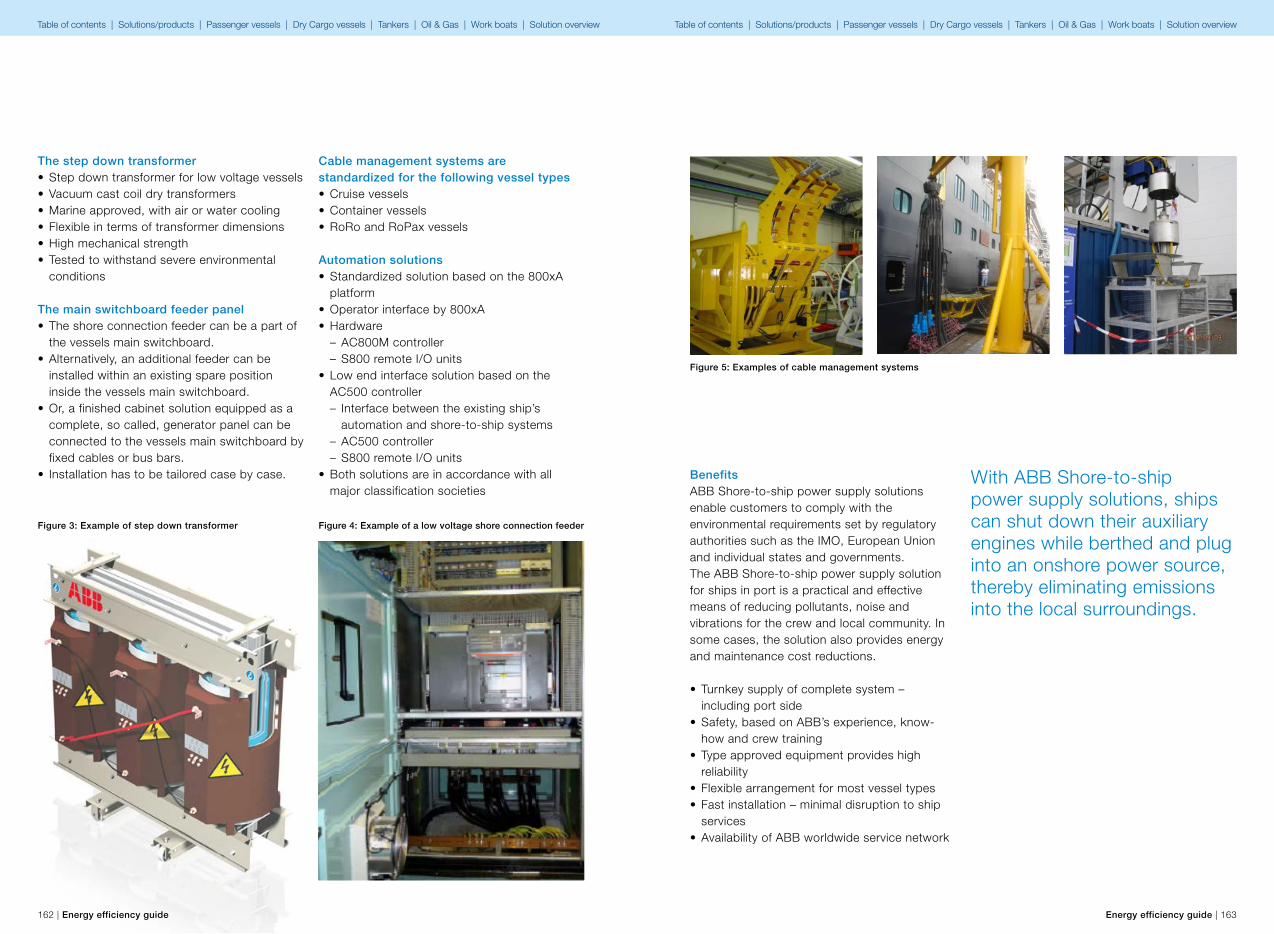
162 | Energy efficiency guide Energy efficiency guide | 163
The step down transformer• Step down transformer for low voltage vessels• Vacuum cast coil dry transformers• Marine approved, with air or water cooling• Flexible in terms of transformer dimensions• High mechanical strength• Tested to withstand severe environmental
conditions
The main switchboard feeder panel• The shore connection feeder can be a part of
the vessels main switchboard.• Alternatively, an additional feeder can be
installed within an existing spare position inside the vessels main switchboard.
• Or, a finished cabinet solution equipped as a complete, so called, generator panel can be connected to the vessels main switchboard by fixed cables or bus bars.
• Installation has to be tailored case by case.
Cable management systems are standardized for the following vessel types• Cruise vessels• Container vessels• RoRo and RoPax vessels
Automation solutions• Standardized solution based on the 800xA
platform• Operator interface by 800xA• Hardware
– AC800M controller – S800 remote I/O units
• Low end interface solution based on the AC500 controller – Interface between the existing ship’s automation and shore-to-ship systems
– AC500 controller – S800 remote I/O units
• Both solutions are in accordance with all major classification societies
Figure 4: Example of a low voltage shore connection feederFigure 3: Example of step down transformer
Figure 5: Examples of cable management systems
BenefitsABB Shore-to-ship power supply solutions enable customers to comply with the environmental requirements set by regulatory authorities such as the IMO, European Union and individual states and governments.The ABB Shore-to-ship power supply solution for ships in port is a practical and effective means of reducing pollutants, noise and vibrations for the crew and local community. In some cases, the solution also provides energy and maintenance cost reductions.
• Turnkey supply of complete system – including port side
• Safety, based on ABB’s experience, know-how and crew training
• Type approved equipment provides high reliability
• Flexible arrangement for most vessel types• Fast installation – minimal disruption to ship
services• Availability of ABB worldwide service network
With ABB Shore-to-ship power supply solutions, ships can shut down their auxiliary engines while berthed and plug into an onshore power source, thereby eliminating emissions into the local surroundings.
Table of contents | Solutions/products | Passenger vessels | Dry Cargo vessels | Tankers | Oil & Gas | Work boats | Solution overview Table of contents | Solutions/products | Passenger vessels | Dry Cargo vessels | Tankers | Oil & Gas | Work boats | Solution overview
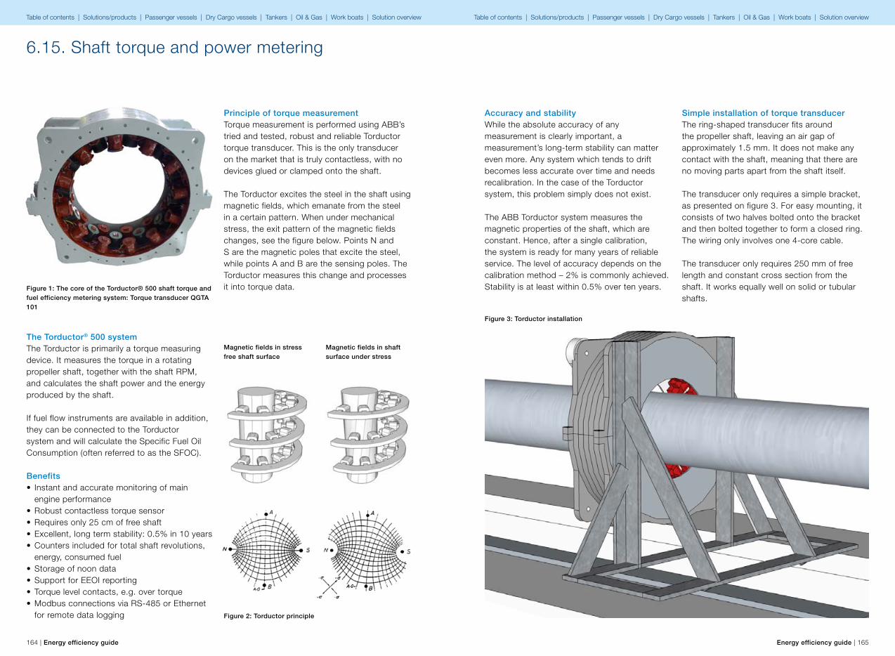
164 | Energy efficiency guide Energy efficiency guide | 165
6.15. Shaft torque and power metering
The Torductor® 500 systemThe Torductor is primarily a torque measuring device. It measures the torque in a rotating propeller shaft, together with the shaft RPM, and calculates the shaft power and the energy produced by the shaft.
If fuel flow instruments are available in addition, they can be connected to the Torductor system and will calculate the Specific Fuel Oil Consumption (often referred to as the SFOC).
Benefits• Instant and accurate monitoring of main
engine performance• Robust contactless torque sensor• Requires only 25 cm of free shaft• Excellent, long term stability: 0.5% in 10 years• Counters included for total shaft revolutions,
energy, consumed fuel• Storage of noon data• Support for EEOI reporting• Torque level contacts, e.g. over torque• Modbus connections via RS-485 or Ethernet
for remote data logging
Principle of torque measurementTorque measurement is performed using ABB’s tried and tested, robust and reliable Torductor torque transducer. This is the only transducer on the market that is truly contactless, with no devices glued or clamped onto the shaft.
The Torductor excites the steel in the shaft using magnetic fields, which emanate from the steel in a certain pattern. When under mechanical stress, the exit pattern of the magnetic fields changes, see the figure below. Points N and S are the magnetic poles that excite the steel, while points A and B are the sensing poles. The Torductor measures this change and processes it into torque data.
Magnetic fields in stress free shaft surface
Figure 2: Torductor principle
Magnetic fields in shaft surface under stress
Figure 1: The core of the Torductor® 500 shaft torque and fuel efficiency metering system: Torque transducer QGTA 101
Accuracy and stabilityWhile the absolute accuracy of any measurement is clearly important, a measurement’s long-term stability can matter even more. Any system which tends to drift becomes less accurate over time and needs recalibration. In the case of the Torductor system, this problem simply does not exist.
The ABB Torductor system measures the magnetic properties of the shaft, which are constant. Hence, after a single calibration, the system is ready for many years of reliable service. The level of accuracy depends on the calibration method – 2% is commonly achieved. Stability is at least within 0.5% over ten years.
Simple installation of torque transducerThe ring-shaped transducer fits around the propeller shaft, leaving an air gap of approximately 1.5 mm. It does not make any contact with the shaft, meaning that there are no moving parts apart from the shaft itself.
The transducer only requires a simple bracket, as presented on figure 3. For easy mounting, it consists of two halves bolted onto the bracket and then bolted together to form a closed ring. The wiring only involves one 4-core cable.
The transducer only requires 250 mm of free length and constant cross section from the shaft. It works equally well on solid or tubular shafts.
Figure 3: Torductor installation
Table of contents | Solutions/products | Passenger vessels | Dry Cargo vessels | Tankers | Oil & Gas | Work boats | Solution overview Table of contents | Solutions/products | Passenger vessels | Dry Cargo vessels | Tankers | Oil & Gas | Work boats | Solution overview
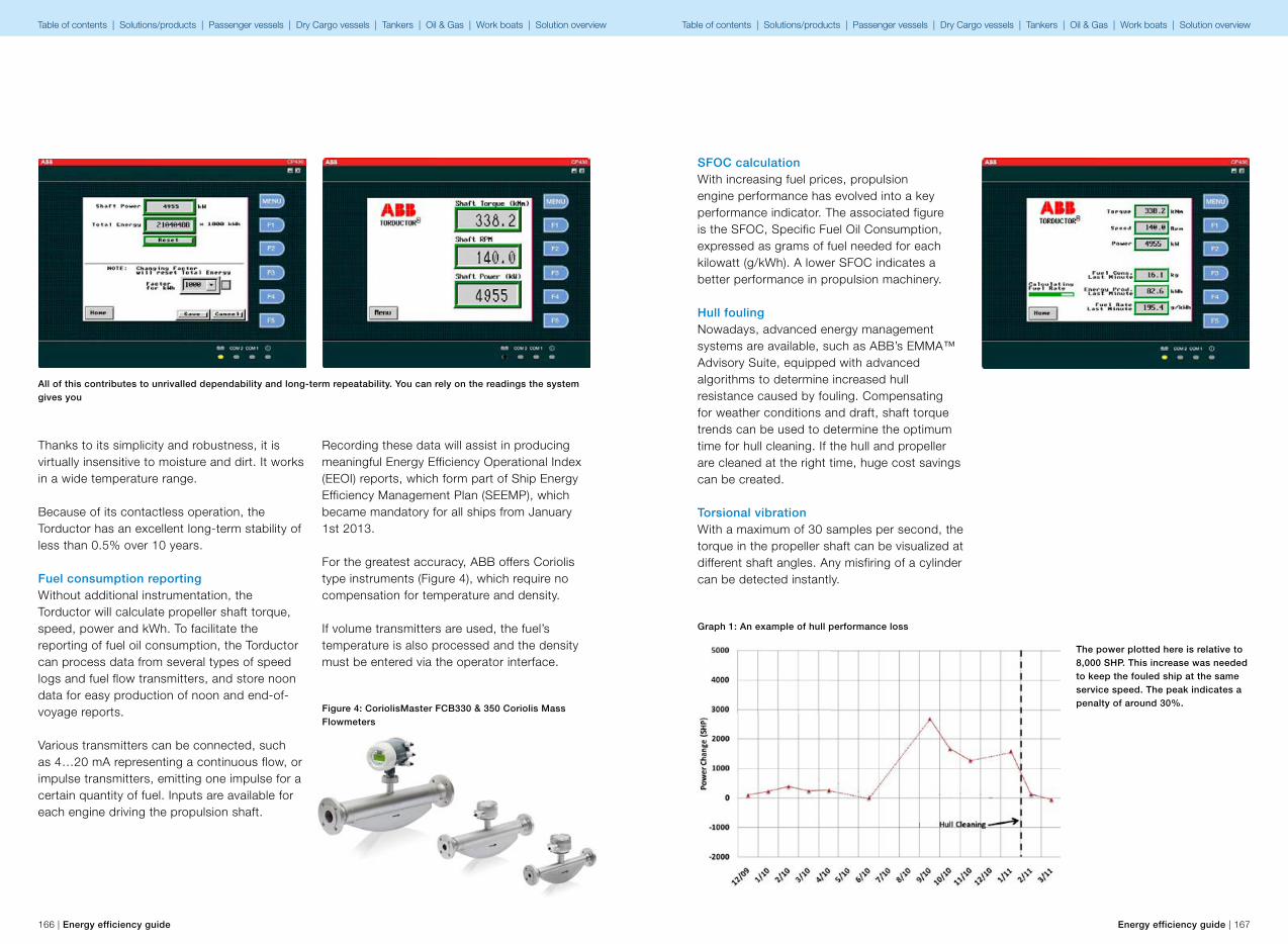
166 | Energy efficiency guide Energy efficiency guide | 167
Thanks to its simplicity and robustness, it is virtually insensitive to moisture and dirt. It works in a wide temperature range.
Because of its contactless operation, the Torductor has an excellent long-term stability of less than 0.5% over 10 years.
Fuel consumption reportingWithout additional instrumentation, the Torductor will calculate propeller shaft torque, speed, power and kWh. To facilitate the reporting of fuel oil consumption, the Torductor can process data from several types of speed logs and fuel flow transmitters, and store noon data for easy production of noon and end-of-voyage reports.
Various transmitters can be connected, such as 4…20 mA representing a continuous flow, or impulse transmitters, emitting one impulse for a certain quantity of fuel. Inputs are available for each engine driving the propulsion shaft.
All of this contributes to unrivalled dependability and long-term repeatability. You can rely on the readings the system gives you
Recording these data will assist in producing meaningful Energy Efficiency Operational Index (EEOI) reports, which form part of Ship Energy Efficiency Management Plan (SEEMP), which became mandatory for all ships from January 1st 2013.
For the greatest accuracy, ABB offers Coriolis type instruments (Figure 4), which require no compensation for temperature and density.
If volume transmitters are used, the fuel’s temperature is also processed and the density must be entered via the operator interface.
Figure 4: CoriolisMaster FCB330 & 350 Coriolis Mass Flowmeters
SFOC calculationWith increasing fuel prices, propulsion engine performance has evolved into a key performance indicator. The associated figure is the SFOC, Specific Fuel Oil Consumption, expressed as grams of fuel needed for each kilowatt (g/kWh). A lower SFOC indicates a better performance in propulsion machinery.
Hull foulingNowadays, advanced energy management systems are available, such as ABB’s EMMA™ Advisory Suite, equipped with advanced algorithms to determine increased hull resistance caused by fouling. Compensating for weather conditions and draft, shaft torque trends can be used to determine the optimum time for hull cleaning. If the hull and propeller are cleaned at the right time, huge cost savings can be created.
Torsional vibrationWith a maximum of 30 samples per second, the torque in the propeller shaft can be visualized at different shaft angles. Any misfiring of a cylinder can be detected instantly.
Graph 1: An example of hull performance loss
The power plotted here is relative to 8,000 SHP. This increase was needed to keep the fouled ship at the same service speed. The peak indicates a penalty of around 30%.
Table of contents | Solutions/products | Passenger vessels | Dry Cargo vessels | Tankers | Oil & Gas | Work boats | Solution overview Table of contents | Solutions/products | Passenger vessels | Dry Cargo vessels | Tankers | Oil & Gas | Work boats | Solution overview
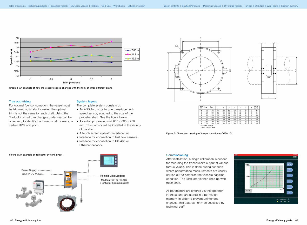
168 | Energy efficiency guide Energy efficiency guide | 169
Graph 2: An example of how the vessel’s speed changes with the trim, at three different drafts
System layoutThe complete system consists of:• An ABB Torductor torque transducer with
speed sensor, adapted to the size of the propeller shaft. See the figure below.
• A central processing unit 600 x 600 x 250 mm. This unit should be installed in the vicinity of the shaft.
• A touch screen operator interface unit• Interface for connection to fuel flow sensors• Interface for connection to RS-485 or
Ethernet network.
Trim optimizingFor optimal fuel consumption, the vessel must be trimmed optimally. However, the optimal trim is not the same for each draft. Using the Torductor, small trim changes underway can be observed, to identify the lowest shaft power at a certain RPM and pitch.
Figure 5: An example of Torductor system layout CommissioningAfter installation, a single calibration is needed for recording the transducer’s output at various torque values. This is done during sea trials, where performance measurements are usually carried out to establish the vessel’s baseline condition. The Torductor is then lined up with these data.
All parameters are entered via the operator interface and are stored in a permanent memory. In order to prevent unintended changes, this data can only be accessed by technical staff.
Figure 6: Dimension drawing of torque transducer QGTA 101
Table of contents | Solutions/products | Passenger vessels | Dry Cargo vessels | Tankers | Oil & Gas | Work boats | Solution overview Table of contents | Solutions/products | Passenger vessels | Dry Cargo vessels | Tankers | Oil & Gas | Work boats | Solution overview
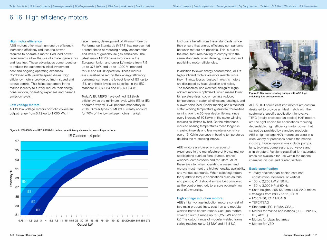
170 | Energy efficiency guide Energy efficiency guide | 171
6.16. High efficiency motors
High motor efficiencyABB motors offer maximum energy efficiency. Increased efficiency reduces the power required to operate a motor. Reduced power requirements allow the use of smaller generators and less fuel. These advantages come together to reduce the customer’s initial investment cost and ongoing operating expenses. Combined with variable speed drives, high efficiency motors provide optimum speed and torque control. This helps customers in the marine industry to further reduce their energy consumption, operating expenses and harmful emission levels.
Low voltage motorsABB’s low voltage motors portfolio covers an output range from 0.12 up to 1,000 kW. In
recent years, development of Minimum Energy Performance Standards (MEPS) has represented a trend aimed at reducing energy consumption and levels of greenhouse gas emissions. The latest major MEPS came into force in the European Union and cover LV motors from 7.5 up to 375 kW, and up to 1,000 V, intended for 50 and 60 Hz operation. These motors are classified based on their energy efficiency performance, from the lowest level of IE1 up to IE4, and these levels are specified in the IEC standard IEC 60034 and IEC 60034-31.
Today’s EU MEPS have defined IE2 (high efficiency) as the minimum level, while IE3 or IE2 operated with VFD will become mandatory in 2015. Similar types of MEPS currently account for 70% of the low voltage motors market.
Figure 1: IEC 60034 and IEC 60034-31 define the efficiency classes for low voltage motors.
End users benefit from these standards, since they ensure that energy efficiency comparisons between motors are possible. This is due to the manufacturers having to comply with the same standards when defining, measuring and publishing motor efficiencies.
In addition to lower energy consumption, ABB’s highly efficient motors are more reliable, since they minimize losses. Losses in electric motors are dissipated by heat, vibration and noise. The mechanical and electrical design of highly efficient motors is optimized, which means lower temperature rises, cooler running, reduced temperatures in stator windings and bearings, and a lower noise level. Cooler running and a reduced stator winding temperature guarantee trouble-free running over the 30-year design lifetime, since every increase of 10 Kelvin in the stator winding reduces its lifetime by half. On the other hand, reduced bearing temperatures mean longer re-creasing intervals and less maintenance, since every 15-Kelvin decrease in bearing temperatures doubles the re-creasing interval.
ABB motors are based on decades of experience in the manufacture of typical marine applications such as fans, pumps, cranes, winches, compressors and thrusters. All of these are vital when operating a vessel, and motors must meet the highest quality, availability and various standards. When selecting motors for quadratic torque applications such as fans and pumps, VFD should always be considered as the control method, to ensure optimally low cost of ownership.
High voltage induction motorsABB’s high voltage induction motors consist of two main product lines, cast iron and modular welded frame constructions. Cast iron motors cover an output range up to 2,250 kW and 11.5 kV. The output range of modular welded frame series reaches up to 23 MW and 13.8 kV.
ABB’s HXR-series cast iron motors are custom designed to provide an ideal match with the customer’s specific application. Innovative, TEFC (totally enclosed fan cooled) HXR motors are the right choice for applications requiring dependable, high efficiency motor power that cannot be provided by standard products. ABB’s high voltage HXR motors are used in a wide variety of processes across the marine industry. Typical applications include pumps, fans, blowers, compressors, conveyors and ship thrusters. Versions classified for hazardous areas are available for use within the marine, chemical, oil, gas and related sectors.
Basic specification• Totally enclosed fan-cooled cast iron
construction, horizontal or vertical• 100 to 2,250 kW at 50 Hz• 150 to 3,000 HP at 60 Hz• Shaft heights: 355-560 mm 14.5-22.0 inches• Voltages from 380 V to 11,500 V• IP55/IP56, IC411/IC416• TEFC/TEAO• Standards IEC, NEMA, CSA...• Motors for marine applications (LRS, DNV, BV,
GL, ABS...)• Motors for classified areas• Motors for VSD
Figure 2: Sea water cooling pumps with ABB high efficiency low voltage motors.
Table of contents | Solutions/products | Passenger vessels | Dry Cargo vessels | Tankers | Oil & Gas | Work boats | Solution overview Table of contents | Solutions/products | Passenger vessels | Dry Cargo vessels | Tankers | Oil & Gas | Work boats | Solution overview
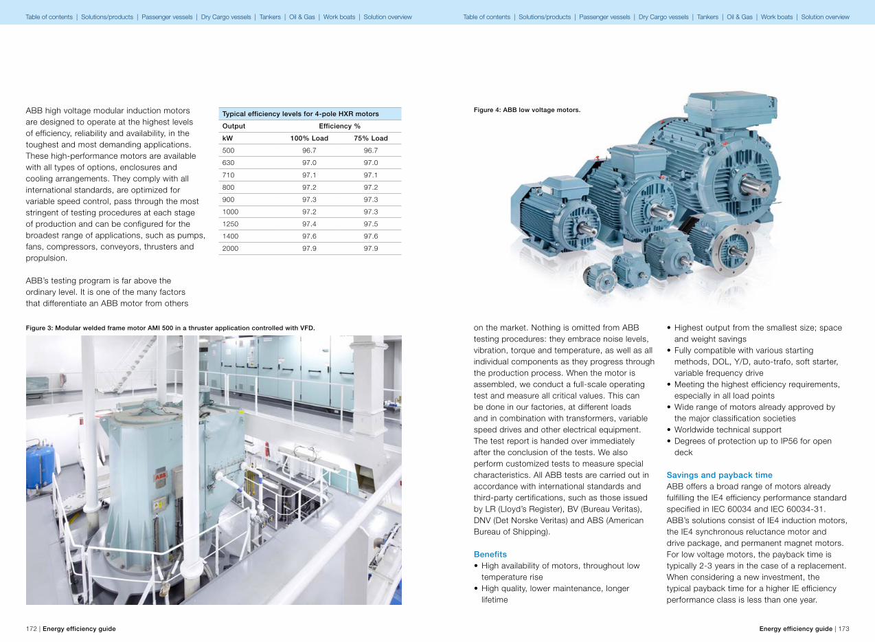
172 | Energy efficiency guide Energy efficiency guide | 173
ABB high voltage modular induction motors are designed to operate at the highest levels of efficiency, reliability and availability, in the toughest and most demanding applications. These high-performance motors are available with all types of options, enclosures and cooling arrangements. They comply with all international standards, are optimized for variable speed control, pass through the most stringent of testing procedures at each stage of production and can be configured for the broadest range of applications, such as pumps, fans, compressors, conveyors, thrusters and propulsion.
ABB’s testing program is far above the ordinary level. It is one of the many factors that differentiate an ABB motor from others
Typical efficiency levels for 4-pole HXR motors
Output Efficiency %
kW 100% Load 75% Load
500 96.7 96.7
630 97.0 97.0
710 97.1 97.1
800 97.2 97.2
900 97.3 97.3
1000 97.2 97.3
1250 97.4 97.5
1400 97.6 97.6
2000 97.9 97.9
Figure 3: Modular welded frame motor AMI 500 in a thruster application controlled with VFD.
Figure 4: ABB low voltage motors.
on the market. Nothing is omitted from ABB testing procedures: they embrace noise levels, vibration, torque and temperature, as well as all individual components as they progress through the production process. When the motor is assembled, we conduct a full-scale operating test and measure all critical values. This can be done in our factories, at different loads and in combination with transformers, variable speed drives and other electrical equipment. The test report is handed over immediately after the conclusion of the tests. We also perform customized tests to measure special characteristics. All ABB tests are carried out in accordance with international standards and third-party certifications, such as those issued by LR (Lloyd’s Register), BV (Bureau Veritas), DNV (Det Norske Veritas) and ABS (American Bureau of Shipping).
Benefits• High availability of motors, throughout low
temperature rise• High quality, lower maintenance, longer
lifetime
• Highest output from the smallest size; space and weight savings
• Fully compatible with various starting methods, DOL, Y/D, auto-trafo, soft starter, variable frequency drive
• Meeting the highest efficiency requirements, especially in all load points
• Wide range of motors already approved by the major classification societies
• Worldwide technical support• Degrees of protection up to IP56 for open
deck
Savings and payback timeABB offers a broad range of motors already fulfilling the IE4 efficiency performance standard specified in IEC 60034 and IEC 60034-31. ABB’s solutions consist of IE4 induction motors, the IE4 synchronous reluctance motor and drive package, and permanent magnet motors. For low voltage motors, the payback time is typically 2-3 years in the case of a replacement. When considering a new investment, the typical payback time for a higher IE efficiency performance class is less than one year.
Table of contents | Solutions/products | Passenger vessels | Dry Cargo vessels | Tankers | Oil & Gas | Work boats | Solution overview Table of contents | Solutions/products | Passenger vessels | Dry Cargo vessels | Tankers | Oil & Gas | Work boats | Solution overview
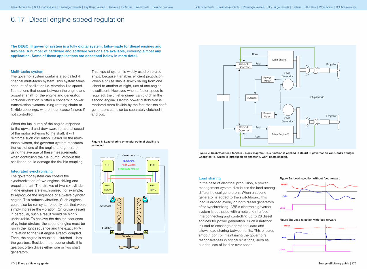
174 | Energy efficiency guide Energy efficiency guide | 175
6.17. Diesel engine speed regulation
The DEGO III governor system is a fully digital system, tailor-made for diesel engines and turbines. A number of hardware and software versions are available, covering almost any application. Some of these applications are described below in more detail.
This type of system is widely used on cruise ships, because it enables efficient propulsion. When a cruise ship is slowly sailing from one island to another at night, use of one engine is sufficient. However, when a faster speed is required, the chief engineer can clutch in the second engine. Electric power distribution is rendered more flexible by the fact that the shaft generators can also be separately clutched in and out.
Gearbox
Actuators
Governors
Clutches
INDIVIDUAL
PORT MASTER
STARBOARD MASTER
FUEL
SERVO
P I D
FUEL
SERVO
P I D
Figure 1: Load sharing principle; optimal stability is achieved
Multi-tacho systemThe governor system contains a so-called 4 channel multi-tacho system. This system takes account of oscillation i.e. vibration-like speed fluctuations that occur between the engine and propeller shaft, or the engine and generator. Torsional vibration is often a concern in power transmission systems using rotating shafts or flexible couplings, where it can cause failures if not controlled.
When the fuel pump of the engine responds to the upward and downward rotational speed of the motor adhering to the shaft, it will reinforce such oscillation. Based on the multi-tacho system, the governor system measures the revolutions of the engine and generator, using the average of these measurements when controlling the fuel pump. Without this, oscillation could damage the flexible coupling.
Integrated synchronizingThe governor system can control the synchronization of two engines driving one propeller shaft. The strokes of two six-cylinder in-line engines are synchronized, for example, to reproduce the sequence of a twelve cylinder engine. This reduces vibration. Such engines could also be run synchronously, but that would simply increase the vibration. On cruise vessels in particular, such a result would be highly undesirable. To achieve the desired sequence of cylinder strokes, the second engine must be run in the right sequence and the exact RPM, in relation to the first engine already coupled. Then, the engine is coupled – clutched – into the gearbox. Besides the propeller shaft, this gearbox often drives either one or two shaft generators.
Load sharingIn the case of electrical propulsion, a power management system distributes the load among different diesel generators. When a second generator is added to the switchboard, this load is divided evenly on both diesel generators after synchronizing. ABB’s electronic governor system is equipped with a network interface interconnecting and controlling up to 28 diesel engines for power generation. Such a network is used to exchange operational data and allows load sharing between units. This ensures smooth control, maintaining the governor’s responsiveness in critical situations, such as sudden loss of load or over speed.
Figure 2: Calibrated feed forward - block diagram. This function is applied in DEGO III governor on Van Oord’s dredger Geopotes 15, which is introduced on chapter 4, work boats section.
Figure 3a: Load rejection without feed forward
Figure 3b: Load rejection with feed forward
Rpm
Rpm
Fuel
Fuel Propeller
Propeller
Ships’s Grid
ShaftGenerator
ShaftGenerator
Main Engine 1
PowerMeter
PowerMeter
Average
DEGO IIIGovernor
DEGO IIIGovernor
Main Engine 2
Table of contents | Solutions/products | Passenger vessels | Dry Cargo vessels | Tankers | Oil & Gas | Work boats | Solution overview Table of contents | Solutions/products | Passenger vessels | Dry Cargo vessels | Tankers | Oil & Gas | Work boats | Solution overview
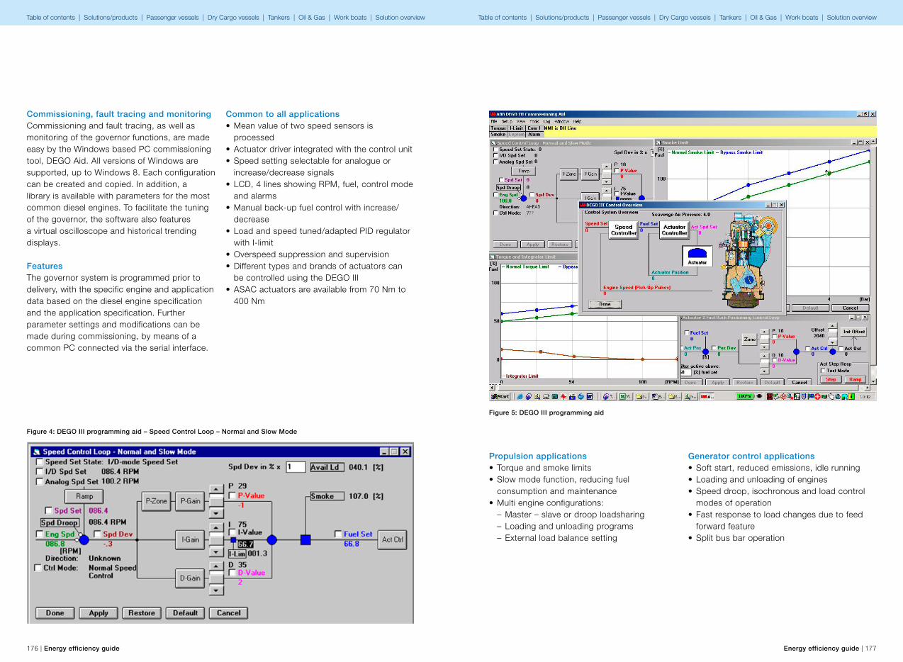
176 | Energy efficiency guide Energy efficiency guide | 177
Figure 4: DEGO III programming aid – Speed Control Loop – Normal and Slow Mode
Commissioning, fault tracing and monitoringCommissioning and fault tracing, as well as monitoring of the governor functions, are made easy by the Windows based PC commissioning tool, DEGO Aid. All versions of Windows are supported, up to Windows 8. Each configuration can be created and copied. In addition, a library is available with parameters for the most common diesel engines. To facilitate the tuning of the governor, the software also features a virtual oscilloscope and historical trending displays.
FeaturesThe governor system is programmed prior to delivery, with the specific engine and application data based on the diesel engine specification and the application specification. Further parameter settings and modifications can be made during commissioning, by means of a common PC connected via the serial interface.
Common to all applications• Mean value of two speed sensors is
processed• Actuator driver integrated with the control unit• Speed setting selectable for analogue or
increase/decrease signals• LCD, 4 lines showing RPM, fuel, control mode
and alarms• Manual back-up fuel control with increase/
decrease• Load and speed tuned/adapted PID regulator
with I-limit• Overspeed suppression and supervision• Different types and brands of actuators can
be controlled using the DEGO III• ASAC actuators are available from 70 Nm to
400 Nm
Figure 5: DEGO III programming aid
Propulsion applications• Torque and smoke limits• Slow mode function, reducing fuel
consumption and maintenance• Multi engine configurations:
– Master – slave or droop loadsharing – Loading and unloading programs – External load balance setting
Generator control applications• Soft start, reduced emissions, idle running• Loading and unloading of engines• Speed droop, isochronous and load control
modes of operation• Fast response to load changes due to feed
forward feature• Split bus bar operation
Table of contents | Solutions/products | Passenger vessels | Dry Cargo vessels | Tankers | Oil & Gas | Work boats | Solution overview Table of contents | Solutions/products | Passenger vessels | Dry Cargo vessels | Tankers | Oil & Gas | Work boats | Solution overview
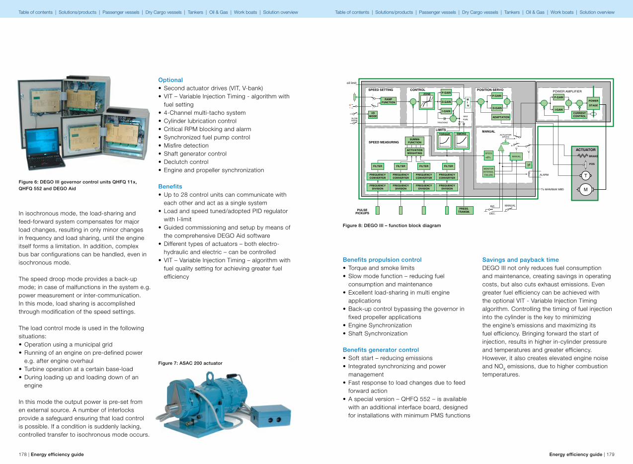
RAMPFUNCTION
+-
I/DMODE
SPEED SETTINGZONE P-GAIN
D-GAIN
I-GAIN
CONTROL
ADAPTATION
P-GAIN
D-GAIN
FILTER
POWER
STAGEI-GAIN
P-GAIN
CURRENTCONTROL
POWER AMPLIFIER
ACTUATOR
POSITION SERVO
MANUAL
INC.
DEC.
SUMMAFUNCTION
PICKUPS
FREQUENCYCONVERTER
FREQUENCYDIVISION
FREQUENCYCONVERTER
FREQUENCYDIVISION
FREQUENCYCONVERTER
FREQUENCYDIVISION
FREQUENCYCONVERTER
FREQUENCYDIVISION
SPEED MEASURING
PRESS.TRANSM.
LIMITS
PULSE
MAXFUEL
TRACKING
SLOWMODE
ACTUATORSPEED
+
>1
MANUAL
SMOKETORQUE
<6%
MONITORINTERNALFAILURE
MANUAL
SPEED
ALARM
BRAKE
POSFILTER FILTER FILTER
ACTIVATIONWEIGHTING
T
M
MIN
oil limit
To MAN/B&W MBD
178 | Energy efficiency guide Energy efficiency guide | 179
Figure 7: ASAC 200 actuator
In isochronous mode, the load-sharing and feed-forward system compensates for major load changes, resulting in only minor changes in frequency and load sharing, until the engine itself forms a limitation. In addition, complex bus bar configurations can be handled, even in isochronous mode.
The speed droop mode provides a back-up mode; in case of malfunctions in the system e.g. power measurement or inter-communication. In this mode, load sharing is accomplished through modification of the speed settings.
The load control mode is used in the following situations:• Operation using a municipal grid• Running of an engine on pre-defined power
e.g. after engine overhaul• Turbine operation at a certain base-load• During loading up and loading down of an
engine
In this mode the output power is pre-set from en external source. A number of interlocks provide a safeguard ensuring that load control is possible. If a condition is suddenly lacking, controlled transfer to isochronous mode occurs.
Optional• Second actuator drives (VIT, V-bank)• VIT – Variable Injection Timing - algorithm with
fuel setting• 4-Channel multi-tacho system• Cylinder lubrication control• Critical RPM blocking and alarm• Synchronized fuel pump control• Misfire detection• Shaft generator control• Declutch control• Engine and propeller synchronization
Benefits • Up to 28 control units can communicate with
each other and act as a single system• Load and speed tuned/adopted PID regulator
with I-limit• Guided commissioning and setup by means of
the comprehensive DEGO Aid software• Different types of actuators – both electro-
hydraulic and electric – can be controlled• VIT – Variable Injection Timing – algorithm with
fuel quality setting for achieving greater fuel efficiency
Figure 6: DEGO III governor control units QHFQ 11x, QHFQ 552 and DEGO Aid
Figure 8: DEGO III – function block diagram
Benefits propulsion control• Torque and smoke limits• Slow mode function – reducing fuel
consumption and maintenance• Excellent load-sharing in multi engine
applications• Back-up control bypassing the governor in
fixed propeller applications• Engine Synchronization• Shaft Synchronization
Benefits generator control• Soft start – reducing emissions• Integrated synchronizing and power
management• Fast response to load changes due to feed
forward action• A special version – QHFQ 552 – is available
with an additional interface board, designed for installations with minimum PMS functions
Savings and payback timeDEGO III not only reduces fuel consumption and maintenance, creating savings in operating costs, but also cuts exhaust emissions. Even greater fuel efficiency can be achieved with the optional VIT - Variable Injection Timing algorithm. Controlling the timing of fuel injection into the cylinder is the key to minimizing the engine’s emissions and maximizing its fuel efficiency. Bringing forward the start of injection, results in higher in-cylinder pressure and temperatures and greater efficiency. However, it also creates elevated engine noise and NOX emissions, due to higher combustion temperatures.
Table of contents | Solutions/products | Passenger vessels | Dry Cargo vessels | Tankers | Oil & Gas | Work boats | Solution overview Table of contents | Solutions/products | Passenger vessels | Dry Cargo vessels | Tankers | Oil & Gas | Work boats | Solution overview
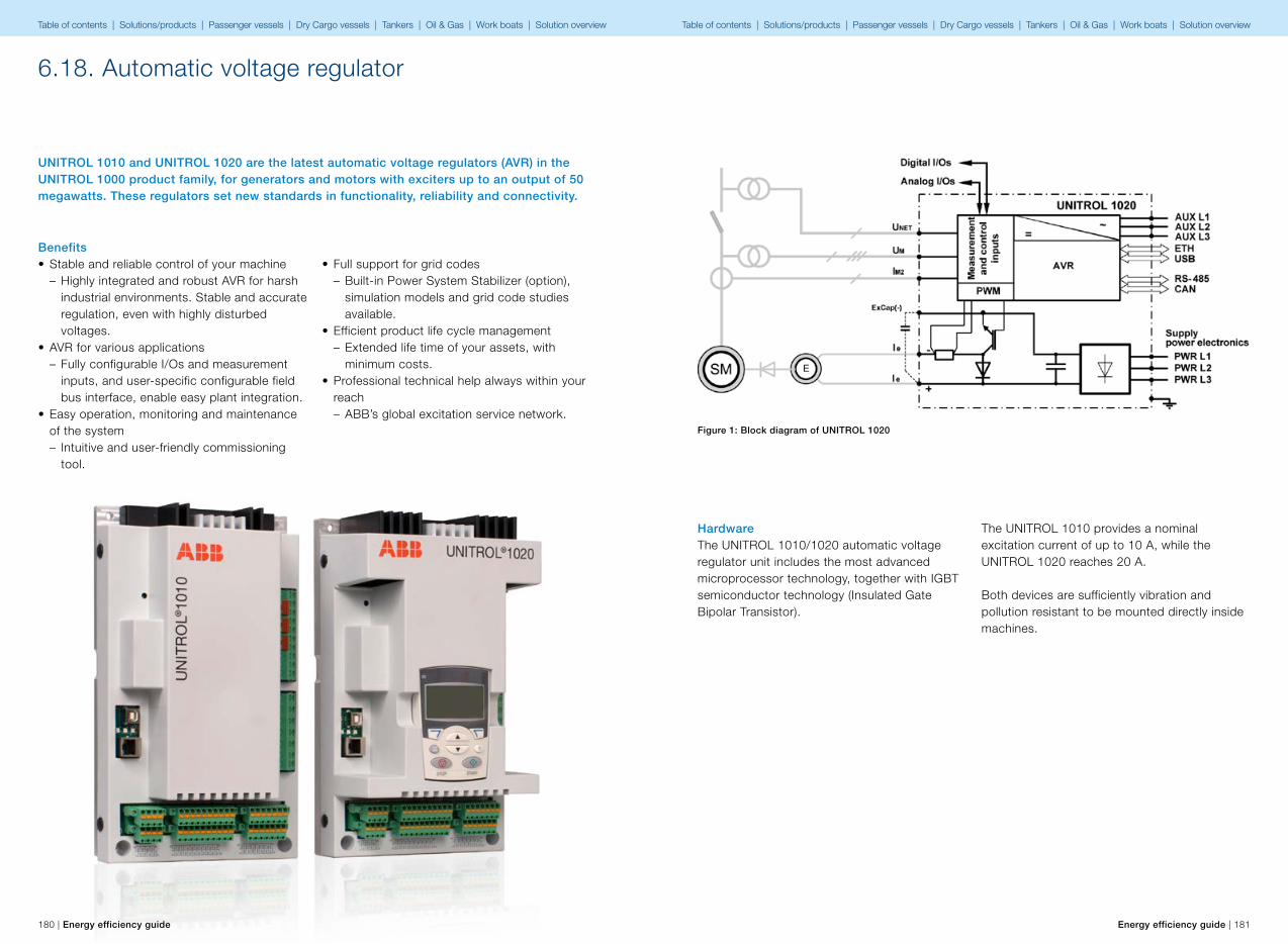
180 | Energy efficiency guide Energy efficiency guide | 181
UNITROL 1010 and UNITROL 1020 are the latest automatic voltage regulators (AVR) in the UNITROL 1000 product family, for generators and motors with exciters up to an output of 50 megawatts. These regulators set new standards in functionality, reliability and connectivity.
6.18. Automatic voltage regulator
• Full support for grid codes – Built-in Power System Stabilizer (option), simulation models and grid code studies available.
• Efficient product life cycle management – Extended life time of your assets, with minimum costs.
• Professional technical help always within your reach – ABB’s global excitation service network.
Benefits• Stable and reliable control of your machine
– Highly integrated and robust AVR for harsh industrial environments. Stable and accurate regulation, even with highly disturbed voltages.
• AVR for various applications – Fully configurable I/Os and measurement inputs, and user-specific configurable field bus interface, enable easy plant integration.
• Easy operation, monitoring and maintenance of the system – Intuitive and user-friendly commissioning tool.
HardwareThe UNITROL 1010/1020 automatic voltage regulator unit includes the most advanced microprocessor technology, together with IGBT semiconductor technology (Insulated Gate Bipolar Transistor).
Figure 1: Block diagram of UNITROL 1020
The UNITROL 1010 provides a nominal excitation current of up to 10 A, while the UNITROL 1020 reaches 20 A.
Both devices are sufficiently vibration and pollution resistant to be mounted directly inside machines.
Table of contents | Solutions/products | Passenger vessels | Dry Cargo vessels | Tankers | Oil & Gas | Work boats | Solution overview Table of contents | Solutions/products | Passenger vessels | Dry Cargo vessels | Tankers | Oil & Gas | Work boats | Solution overview
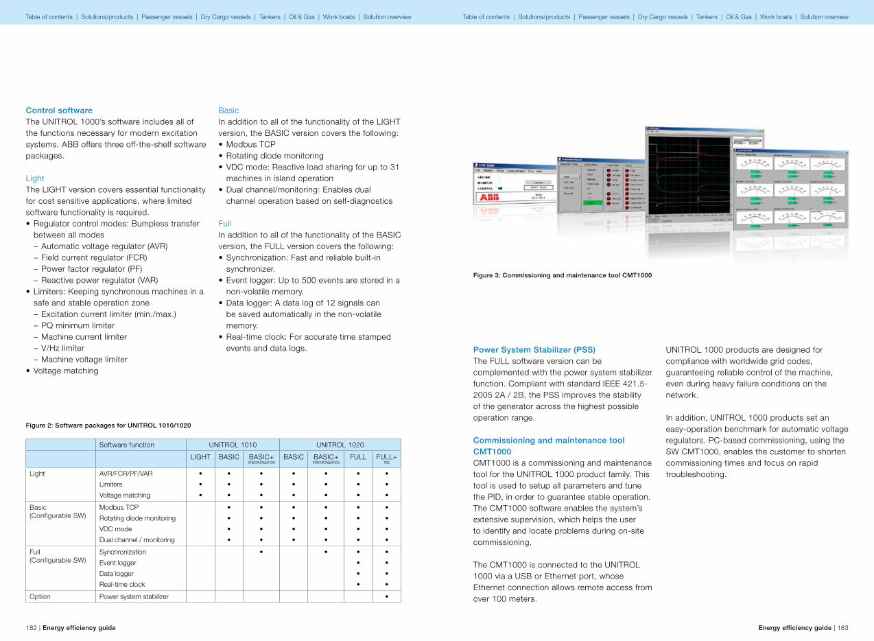
182 | Energy efficiency guide Energy efficiency guide | 183
Control softwareThe UNITROL 1000’s software includes all of the functions necessary for modern excitation systems. ABB offers three off-the-shelf software packages.
LightThe LIGHT version covers essential functionality for cost sensitive applications, where limited software functionality is required.• Regulator control modes: Bumpless transfer
between all modes – Automatic voltage regulator (AVR) – Field current regulator (FCR) – Power factor regulator (PF) – Reactive power regulator (VAR)
• Limiters: Keeping synchronous machines in a safe and stable operation zone – Excitation current limiter (min./max.) – PQ minimum limiter – Machine current limiter – V/Hz limiter – Machine voltage limiter
• Voltage matching
BasicIn addition to all of the functionality of the LIGHT version, the BASIC version covers the following:• Modbus TCP• Rotating diode monitoring• VDC mode: Reactive load sharing for up to 31
machines in island operation• Dual channel/monitoring: Enables dual
channel operation based on self-diagnostics
FullIn addition to all of the functionality of the BASIC version, the FULL version covers the following:• Synchronization: Fast and reliable built-in
synchronizer.• Event logger: Up to 500 events are stored in a
non-volatile memory. • Data logger: A data log of 12 signals can
be saved automatically in the non-volatile memory.
• Real-time clock: For accurate time stamped events and data logs.
Figure 2: Software packages for UNITROL 1010/1020
Software function UNITROL 1010 UNITROL 1020
LIGHT BASIC BASIC+SYNCHRONIZATION
BASIC BASIC+SYNCHRONIZATION
FULL FULL+PSS
Light AVR/FCR/PF/VAR
Limiters
Voltage matching
•
•
•
•
•
•
•
•
•
•
•
•
•
•
•
•
•
•
•
•
•
Basic(Configurable SW)
Modbus TCP
Rotating diode monitoring
VDC mode
Dual channel / monitoring
•
•
•
•
•
•
•
•
•
•
•
•
•
•
•
•
•
•
•
•
•
•
•
•
Full(Configurable SW)
Synchronization
Event logger
Data logger
Real-time clock
• • •
•
•
•
•
•
•
•
Option Power system stabilizer •
Power System Stabilizer (PSS)The FULL software version can be complemented with the power system stabilizer function. Compliant with standard IEEE 421.5-2005 2A / 2B, the PSS improves the stability of the generator across the highest possible operation range.
Commissioning and maintenance tool CMT1000CMT1000 is a commissioning and maintenance tool for the UNITROL 1000 product family. This tool is used to setup all parameters and tune the PID, in order to guarantee stable operation. The CMT1000 software enables the system’s extensive supervision, which helps the user to identify and locate problems during on-site commissioning.
The CMT1000 is connected to the UNITROL 1000 via a USB or Ethernet port, whose Ethernet connection allows remote access from over 100 meters.
UNITROL 1000 products are designed for compliance with worldwide grid codes, guaranteeing reliable control of the machine, even during heavy failure conditions on the network.
In addition, UNITROL 1000 products set an easy-operation benchmark for automatic voltage regulators. PC-based commissioning, using the SW CMT1000, enables the customer to shorten commissioning times and focus on rapid troubleshooting.
Figure 3: Commissioning and maintenance tool CMT1000
Table of contents | Solutions/products | Passenger vessels | Dry Cargo vessels | Tankers | Oil & Gas | Work boats | Solution overview Table of contents | Solutions/products | Passenger vessels | Dry Cargo vessels | Tankers | Oil & Gas | Work boats | Solution overview
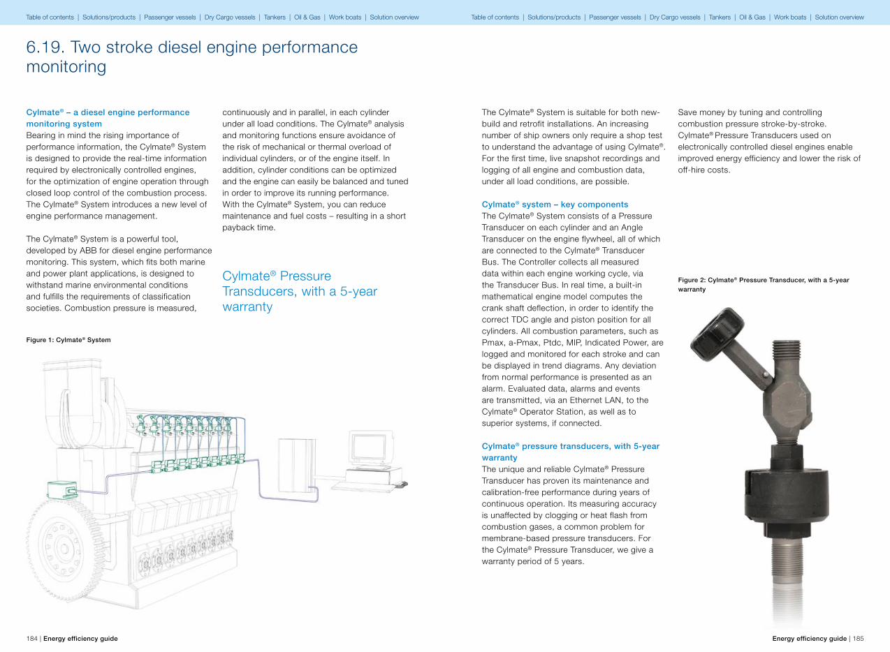
184 | Energy efficiency guide Energy efficiency guide | 185
Cylmate® Pressure Transducers, with a 5-year warranty
6.19. Two stroke diesel engine performance monitoring
Cylmate® – a diesel engine performance monitoring systemBearing in mind the rising importance of performance information, the Cylmate® System is designed to provide the real-time information required by electronically controlled engines, for the optimization of engine operation through closed loop control of the combustion process. The Cylmate® System introduces a new level of engine performance management.
The Cylmate® System is a powerful tool, developed by ABB for diesel engine performance monitoring. This system, which fits both marine and power plant applications, is designed to withstand marine environmental conditions and fulfills the requirements of classification societies. Combustion pressure is measured,
continuously and in parallel, in each cylinder under all load conditions. The Cylmate® analysis and monitoring functions ensure avoidance of the risk of mechanical or thermal overload of individual cylinders, or of the engine itself. In addition, cylinder conditions can be optimized and the engine can easily be balanced and tuned in order to improve its running performance. With the Cylmate® System, you can reduce maintenance and fuel costs – resulting in a short payback time.
Figure 1: Cylmate® System
The Cylmate® System is suitable for both new-build and retrofit installations. An increasing number of ship owners only require a shop test to understand the advantage of using Cylmate®. For the first time, live snapshot recordings and logging of all engine and combustion data, under all load conditions, are possible.
Cylmate® system – key componentsThe Cylmate® System consists of a Pressure Transducer on each cylinder and an Angle Transducer on the engine flywheel, all of which are connected to the Cylmate® Transducer Bus. The Controller collects all measured data within each engine working cycle, via the Transducer Bus. In real time, a built-in mathematical engine model computes the crank shaft deflection, in order to identify the correct TDC angle and piston position for all cylinders. All combustion parameters, such as Pmax, a-Pmax, Ptdc, MIP, Indicated Power, are logged and monitored for each stroke and can be displayed in trend diagrams. Any deviation from normal performance is presented as an alarm. Evaluated data, alarms and events are transmitted, via an Ethernet LAN, to the Cylmate® Operator Station, as well as to superior systems, if connected.
Cylmate® pressure transducers, with 5-year warrantyThe unique and reliable Cylmate® Pressure Transducer has proven its maintenance and calibration-free performance during years of continuous operation. Its measuring accuracy is unaffected by clogging or heat flash from combustion gases, a common problem for membrane-based pressure transducers. For the Cylmate® Pressure Transducer, we give a warranty period of 5 years.
Figure 2: Cylmate® Pressure Transducer, with a 5-year warranty
Save money by tuning and controlling combustion pressure stroke-by-stroke. Cylmate® Pressure Transducers used on electronically controlled diesel engines enable improved energy efficiency and lower the risk of off-hire costs.
Table of contents | Solutions/products | Passenger vessels | Dry Cargo vessels | Tankers | Oil & Gas | Work boats | Solution overview Table of contents | Solutions/products | Passenger vessels | Dry Cargo vessels | Tankers | Oil & Gas | Work boats | Solution overview

186 | Energy efficiency guide Energy efficiency guide | 187
Fuel oil consumption can be reduced by around 1– 2%Cylmate® pressure
transducers in closed loop control applications
Cylmate® pressure transducers can also be used stand-alone, and in the closed loop control of fuel injection by engine builders. Cylmate® pressure transducers secure reliable operation, stroke-by-stroke, year-after-year. The maintenance and calibration-free performance of the unique and reliable Cylmate® pressure sensor has been proven during years of continuous operation.
Cylmate® pressure transducers in closed loop control applicationsCylmate® Pressure Transducers can also be used stand-alone and by engine builders for the closed loop control of fuel injection. Cylmate® Pressure Transducers secure reliable operation, stroke-by-stroke, year-after-year. The maintenance and calibration-free performance of the unique and reliable Cylmate® pressure sensor has been proven in years of continuous operation. 5 years warranty.
Recognized, verified and provenCylmate® System has received the CIMAC President’s award and is recognized as the leading solution for engine performance monitoring by ship owners, yards and engine builders. Over the years, the Cylmate® System has proven its outstanding reliability in numerous installations, while its accuracy has been demonstrated in engine shop tests.
Pressure transducer used in closed loop control applications by main engine builders
Benefits• Reduced fuel consumption• Performance monitoring 24/7 detects and
identifies errors in the engine at a very early stage
• An optimized engine enables compliance with environmental regulations
• An engine in good balance avoids thermal and mechanical overloads by ensuring equal power distribution between cylinders
• Pressure transducer used in the closed loop control applications of main engine builders
• Alarm monitoring and trend data recording provides information crucial to optimizing maintenance costs
Savings and payback timeA well tuned and balanced engine consumes less fuel. Using the ABB Cylmate® System, fuel oil consumption can be reduced by around 1–2%, meaning a payback time of less than one year.
Table of contents | Solutions/products | Passenger vessels | Dry Cargo vessels | Tankers | Oil & Gas | Work boats | Solution overview Table of contents | Solutions/products | Passenger vessels | Dry Cargo vessels | Tankers | Oil & Gas | Work boats | Solution overview

188 | Energy efficiency guide Energy efficiency guide | 189
How to proceed7
Table of contents | Solutions/products | Passenger vessels | Dry Cargo vessels | Tankers | Oil & Gas | Work boats Table of contents | Solutions/products | Passenger vessels | Dry Cargo vessels | Tankers | Oil & Gas | Work boats

190 | Energy efficiency guide Energy efficiency guide | 191
7 How to proceed
Fuel efficient
operation
Optimized ship
handling
Hull and
propulsion
Machinery and
equipment
Improved
Cargo
handling
Energy
conservation
and awareness
✔ Improved
voyage planning
✔ Optimum trim ✔ Hull resistance ✔ Propulsion
system
optimization
Cargo handling
optimization
✔ Energy
Management
✘ Weather routing Optimum ballast ✔ Propeller
management
✔ Auxiliary engine
systems
✔ Fuel type
✔ Just-in-time and
improved fleet
management
✔ Optimum
propeller and
propeller inflow
considerations
✔ Waste Heat
Recovery
✔ Use of
renewable
energy
✔ Speed
optimization
Optimum
use of rudder
and heading
control systems
(autopilots)
✔ Auxiliary
systems
✔ Shore to ship
power when at
port
✔ Optimized shaft
power
✔ Training and
awareness
✔ ABB Marine have solution available to improve the energy efficiency in this area✘ ABB Marine can provide a partner solution in delivery
Energy Efficiency – The Other Alternative Fuel
The Ship Energy Efficiency Management Plan (SEEMP) and ABB Marine ServicesSEEMP provides a possible approach to monitoring ship and fleet efficiency performance over time, and some options to be considered when seeking to optimize a ship’s performance.
In the case of SEEMP, the goal is to increase energy efficiency, reduce total fuel costs and lower emissions into the air.
ABB’s Energy Efficiency services, such as the energy efficiency audit, provide a good start in taking a systematic approach to increasing awareness, as well as finding savings in the
places that make most sense to you. The services created by ABB will fully support a ship or company specific SEEMP plan.
While the ultimate operation of a ship involves technical measures, services such as energy efficiency audits and training play a key role in achieving greater operational efficiency.
Summary In the face of high bunker costs, soft freight rates and the hefty price tag attached to upcoming environmental regulations, a familiar feeling is creeping into the decision-making process: the feeling of being “damned if you do, doomed if you don’t.”
Per-Anders Enkvist, associate partner with McKinsey & Company, tells us that “For every year you wait, you not only lose that year, but you lock yourself into a high-carbon world for the next 14 years to come.” In other words, he explains, the expectation is that, across various sectors, the average concentration of
greenhouse gas emissions will peak at 5 ppm (parts per million) higher for every year we wait, not at 2 or 3 ppm, which is the current annual increase.
Because ships are built for a much longer lifetime than 14 years, Enkvist’s example is easy to place in the context of the maritime sector. Every ship being built today will be operating during what we hope will be the peak year for greenhouse gas emissions.
Energy efficiency plays the most important role in CO2 emission reductions, accounting for up to 53% of overall such reductions.
ABB Marine and Cranes is represented in more than 20 countries globally. In each region we have dedicated resources to energy efficiency and SEEMP implementation.Please contact your local ABB Marine representative for more information. www.abb.com/marine
Table of contents | Solutions/products | Passenger vessels | Dry Cargo vessels | Tankers | Oil & Gas | Work boats Table of contents | Solutions/products | Passenger vessels | Dry Cargo vessels | Tankers | Oil & Gas | Work boats

192 | Energy efficiency guide
Editorial Board Heikki Bergman Edward Carney Henrique Pestana Jan-Erik Räsänen Alf Kåre Ådnanes
Project Manager Pertti Jurva
Marketing and Communications Miia Lintunen
Writers Heikki Bergman Tim Ellis Robert Glass Ton Haasdijk Jukka Ignatius Pertti Jurva Lars O Karlsson Eero Laakkonen Jyrki Leino Rudolf Moeckli Gianluca Ormino Henrique Pestana Jacqueline Rolffs Jan-Erik Räsänen Niina Stenius Andree Underthun Jukka Varis Markus Virtasalo Klaus Vänskä Kees de Waard Frank Wendt
Contributors and writers to the guide
Table of contents | Solutions/products | Passenger vessels | Dry Cargo vessels | Tankers | Oil & Gas | Work boats Table of contents | Solutions/products | Passenger vessels | Dry Cargo vessels | Tankers | Oil & Gas | Work boats