energy efficient collaborative single-target …
TRANSCRIPT

TALLINN UNIVERSITY OF TECHNOLOGY
School of Information Technologies
German Mundinger 144314IAPM
ENERGY EFFICIENT COLLABORATIVESINGLE-TARGET TRACKING IN
WIRELESS SENSOR NETWORK WITHLOW POWER MICROWAVE RADAR
SENSORSMaster's thesis
Supervisor: Jaanus Kaugerand
PhD
Co-supervisor: Raido Pahtma
MSc
Tallinn 2021

TALLINNA TEHNIKAÜLIKOOL
Infotehnoloogia teaduskond
German Mundinger 144314IAPM
ENERGIAEFEKTIIVNE ÜHE SIHTMÄRGIJÄLGIMINE TRAADITA ANDURITE
VÕRGUS KOOSTOIMIVATE MADALAVÕIMSUSEGA MIKROLAINERADARI
ANDURITEGAMagistritöö
Juhendaja: Jaanus Kaugerand
PhD
Kaasjuhendaja: Raido Pahtma
MSc
Tallinn 2021

Author’s declaration of originality
I hereby certify that I am the sole author of this thesis. All the used materials, references
to the literature and the work of others have been referred to. This thesis has not been
presented for examination anywhere else.
Author: German Mundinger
06.01.2021
3

Abstract
Smart traffic monitoring systems have a huge impact on a transportation system of
modern towns and life of their citizens. The goal of this thesis is to investigate how to
improve and optimize an existing traffic monitoring system deployed in Tallinn city.
The system includes a wireless sensor network and autonomous low-cost sensor nodes
using solar panel together with rechargeable battery. The current problem with the
traffic sensor nodes is that working alone, they use too much power and the data quality
about the speed of vehicles is volatile. This work focuses on the development of novel
collaborative target tracking solution for embedded Cortex-M4 microcontrollers
equipped with a set of specific low-cost sensor modules – specifically a microwave
radar for detecting vehicle speed and a passive infrared sensor for detecting presence of
a moving vehicle. The basic principles of distributed computing are introduced and
applied during this research to disclose a full potential of that sensor network. The thesis
analyses existing drawbacks of single-node sensing methods, gives a brief explanation
of speed detection algorithm, which converts raw analog signals from microwave sensor
to relevant speed data, and proposes a solution for collaborative sensing. The new
firmware involves a combination of object tracking improvements: activation of nodes
at the borders of monitored area and distributed data processing inside the system. The
research describes in details used approaches and algorithms, which actively utilize a
communication network between devices. However due to complexity of the solution,
the thesis scope is limited by research of two-node tracking scheme and one moving
target at a time. The results are verified experimentally at an urban street with realistic
traffic. The field tests show, that the integrated techniques have a positive effect on the
accuracy of advanced measurements, provided by microwave radar sensors, and the
energy efficiency of the full sensor system.
This thesis is written in English and is 45 pages long, including 6 chapters, 12 figures
and 3 tables.
4

Annotatsioon
Aruka liikluseseire süsteemil on väga suur mõju linnade transpordisüsteemile ja
kodanike elule. Käesoleva lõputöö eesmärk on uurida, kuidas parandada ja optimeerida
Tallinna linnas kasutusel olevat olemasolevat traadita sensorvõrgul põhinevat liikluse
seiresüsteemi. Nimetatud liikluse jälgimissüsteem põhineb autonoomsetel odavatel
sensorseadmetel, mis energiaallikana kasutavad päikesepaneeli koos laetava akuga.
Töös lahendav liiklusandurite probleem seisneb selles, et üksi töötades kasutavad nad
liiga palju energiat ja sensorite poolt mõõdetud sõidukite kiiruse andmete kvaliteet on
madal. Täpsemalt on käesolev töö eesmärk uudse ühise sihtmärgi jälgimise lahenduse
väljatöötamine Cortex-M4 protsessoril põhinevate sardsüsteemide jaoks, mis on
varustatud spetsiaalsete odavate andurimoodulite komplektiga - täpsemalt
mikrolaineradariga sõiduki kiiruse tuvastamiseks ja passiivne infrapunasensor sõiduki
olemasolu tuvastamiseks. Töö tutvustab hajutatud arvutuste põhiprintsiipe ja rakendab
neid uuringu käigus eesmärgiga võtta kasutusele sensorvõrgu koostööst tulenev
potentsiaal. Selleks analüüsitakse kõigepealt hetkel kasutusel olevat üksinda töötava
sensorsõlme seire meetodit ning selgitatakse töös lühidalt kiiruse tuvastamise algoritmi,
mis teisendab mikrolaineandurilt saadud analoogsignaalid asjakohasteks
kiirusandmeteks. Seejärel töötatakse välja uus püsivara sama seireülesande
lahendamiseks mitme sensori koostöös. Uus püsivara hõlmab liikuvate objektide seire
täiustuste kombinatsiooni: sensorseadmete aktiveerimist kui sõiduk siseneb jälgitava ala
piirile ning hajutatud andmetöötlust süsteemi sees. Uuringus kirjeldatakse
üksikasjalikult loodud lähenemisviisi, sõnumsidet ja algoritmi, mis kasutab seadmete
omavahelist sidevõrku aktiivselt. Lahenduse keerukuse tõttu on lõputöö skoop piiratud
kahesõlmelise jälgimisskeemi ja ühe liikuva sihtmärgiga stsenaariumi uurimisega.
Tulemusi kontrollitakse eksperimentaalselt realistliku liiklusega linnatänaval.
Eksperimendi läbiviimiseks kasutatakse samu sensorvõrgu seadmeid mis on reaalselt
Tallinna tänavatel kasutusel. Kontrollkatsed näitavad, et integreeritud lahendusel on
positiivne mõju oluliste mõõtmiste täpsusele ja kogu andurisüsteemi energiatõhususele.
5

Eksperimendi käigus tuvastatud energiatõhususe kasv on enam kui kümnekordne
võrreldes sensoritega mis samu mõõdistusi teostavad individuaalselt.
Lõputöö on kirjutatud inglise keeles ning sisaldab teksti 45 leheküljel, 6 peatükki, 12
joonist, 3 tabelit.
6

List of abbreviations and terms
IoT Internet of Things
MCU Microcontroller unit
ARM Advanced RISC Machines
JTAG Joint Test Action Group
RAM Random-Access Memory
MWD sensor Microwave Doppler sensor
PIR sensor Passive Infrared sensor
CMSIS Cortex Microcontroller Software Interface Standard
RTOS Real-Time Operating System
API Application Programming Interface
WSN Wireless Sensor Network
USB Universal Serial Bus
SmENeTe Smart Environment Networking Technologies
SAA Selective Approach Algorithm
7

Table of Contents
1 Introduction..................................................................................................................11
1.1 Research Problem..................................................................................................12
1.2 Method...................................................................................................................13
1.3 Overview of the Thesis..........................................................................................14
2 Background...................................................................................................................15
2.1 Scope and Features................................................................................................15
2.2 Technical Specification..........................................................................................16
2.3 SmENeTe2 Project................................................................................................18
2.4 Deployment Scheme..............................................................................................20
3 Speed Computing.........................................................................................................22
4 Distributed Tracking.....................................................................................................26
4.1 Theory....................................................................................................................26
4.2 Tracking Session....................................................................................................28
4.3 Collaboration.........................................................................................................31
4.4 Exceptions..............................................................................................................33
5 Field Test......................................................................................................................35
5.1 Setup......................................................................................................................35
5.2 Accuracy of Speed detection.................................................................................36
5.3 Energy Efficiency..................................................................................................38
6 Summary.......................................................................................................................40
6.1 Future Work...........................................................................................................41
References.......................................................................................................................42
Appendix 1 – Non-exclusive licence for reproduction and publication of a graduation
thesis................................................................................................................................44
Appendix 2 – Software Project for Collaborative Tracking............................................45
8

List of Figures
Figure 1: Tracking system context diagram....................................................................15
Figure 2: Tracking system use case diagram...................................................................16
Figure 3: Tracking unit deployment diagram..................................................................17
Figure 4: Tallinn map with deployed SmENeTe2 network.............................................19
Figure 5: Tracking system deployment scheme..............................................................20
Figure 6: Speed detection of a moving away vehicle......................................................23
Figure 7: Speed detection of a moving toward vehicle...................................................25
Figure 8: Tracking session traffic case............................................................................29
Figure 9: Tracking session general activity diagram.......................................................30
Figure 10: Tracking system data flow diagram...............................................................31
Figure 11: Tracking session sequence diagram...............................................................32
Figure 12: Tracking session exceptional traffic cases.....................................................34
9

List of Tables
Table 1: Field test results of 50 km/h speed detection....................................................36
Table 2: Field test results of 30 km/h speed detection....................................................37
Table 3: Field test results of energy efficiency................................................................38
10

1 Introduction
The rapid urbanization of the human population is the reality of life nowadays. The
constant growth of cities has brought new challenges to modern society, including
efficient resource consumption (energy, fuels, water, etc), economic competitiveness,
intelligent transport, participation in governance, ecological security, social capital,
quality of life and other citizen-focused services. That’s why the concept of smart cities
is not only a fashion trend today but also the necessary part of safe and comfortable
urban life, and the key to stable and successful development of growing towns [1].
The British Standards Institute describes smart city as “the effective integration of
physical, digital and human systems in the built environment to deliver sustainable,
prosperous and inclusive future for its citizens” [2]. Smart cities projects involve the
deployment of many Internet of Things (IoT) sensors and networks in a town, which are
interfaced with data centers and decision-making systems. The collaboration of these
components allows to monitor situation in urban area and to manage various physical
infrastructural objects [2].
Transport and logistics have one of the highest priority in the list of smart cities
challenges. These questions are fundamental and very sensitive for large cities, because
intelligently organized and optimized transport system not only saves time and money
but also can save lives. Smart logistic and transportation systems cover a huge range of
problems, including vehicle routing, traffic jams, parking, dynamic message signs,
traffic lightning, motor accidents, public transport, tourism, delivery, etc. This kind of
systems can not become smart without an advanced traffic monitoring network [3].
The purpose of advanced traffic monitoring systems is to collect transport data from
urban traffic infrastructure and to stream this info into management centers in real-time.
The traffic tracking system consists of the field of diverse electronic sensors and video
cameras, which are spread among traffic areas and united by a communication network.
It allows to capture various live-data, such as sensor data about jams and various
11
incidents, road and weather conditions, vehicle counter, speed, class, direction, etc [4].
This work focuses on the research of this kind of systems, mainly on the network of
low-cost energy-limited monitoring devices. More particularly, how to increase the
effectiveness of sensor networks through local collaboration between the electronic
tracking devices, as explained in the next section.
1.1 Research Problem
The problem of traffic monitoring in cities contains a lot of actual topics, which can not
be covered by one research. The thesis focuses on improvements of the existing traffic
monitoring system, which has already deployed along main streets in Tallinn and
involves the large network of tracking devices. Each device is equipped with a motion
sensor, a microwave transceiver, a single-board microcontroller, a solar panel battery
and a rechargeable battery as power supply. In this way, the tracking devices are fully
autonomous and can be deployed anywhere regardless of access to electrical power
grid. Currently, the monitoring devices take motion measurements independently,
without any additional information about a road situation, and this has some negative
aspects: limited continuous power supply and insufficient quality of tracking results. So,
the thesis encompasses three basic questions:
• how to increase the precision of speed estimation?
• how to save energy as much as possible?
• and how to detect motion direction as well?
These challenges can be overcome by different ways, but the ultimate goal of this
research is to investigate how the usage of distributed computing can fix the named
issues and improve the actual tracking solution.
The process of vehicle speed detection in real-time has several difficulties in this
project. Firstly, it requires to analyze and interpret live-data, which arrives from sensors.
The data are raw and noisy, and must be filtered and validated before speed extraction.
Secondly, separate tracking devices need to be well synchronized to each other. The
established distributed system uses messaging to communicate over a wireless network,
12

which must be reliable and fast enough, because the computations are time critical.
Finally, the mentioned tracking units have limited performance and energy resources.
These circumstances force to use additional hardware-specific optimizations for
maximum efficiency. All of the named problems are covered by this thesis.
Also, this research has some limitations. The one of conventionalities is the number of
observable vehicles at a time. Only one moving object is allowed to be in a detection
zone simultaneously. The second important simplification is the quantity of active
monitoring devices, which is equal to two. The last assumption is a permissible range of
speed values. The actual tracking system is designed for urban environment, and with
current configuration it is not possible to monitor vehicles, which move at a speed over
86.8 Km/h.
1.2 Method
The solution for speed detection problem includes hardware and software parts. The
first one is the predefined monitoring system, which can not be modified. So, this work
focuses on software development, which requires embedded programming skills.
The basic approach to solve the problem is the integration of main distributed
computing ideas and messaging into the existing embedded system by implementing
a new firmware, which can be deployed to a monitoring device. The research solution is
developed using C language and CMSIS-RTOS, which is a standardized API, that is
portable to many real-time operating systems. Also, the codebase contains a lot of
hardware specific libraries for working with different peripherals. All of these software
components have raised the level of abstraction and helped to focus on the main
research problems.
The verifying of developed solution in urban situation has a lot of natural
inconveniences. Of course, the development and testing processes were simplified by
using of an extra simulator, which can fake vehicle motion via a USB port. But the main
idea of result validation is to organize field testing. So, when the solution is
implemented and tested in simulation, it will be feasible to verify that in road conditions
experimentally:
13

• to deploy the developed firmware to some monitoring devices
• to collect a sufficient amount of the tracking data (speeds, directions, energy
consumption)
• to compare field test results with outcomes of current tracking solution
(individual sensing)
Only after that, it will be possible to conclude - how the integration of distributed
computing concepts into the existing tracking system can influence to qualities of that
system.
1.3 Overview of the Thesis
The necessary background information and schemes significant for this research are
represented in section 2. The important points about selected traffic monitoring system,
like capabilities, specification and setup, are included in that section.
An introduction of, how single-node speed detection happens, can be found in section 3.
That chapter contains a short description about the transformation of raw signal, which
comes from microwave sensor, into corresponding speed and spectral power data. Also
section 3 overviews the methods, which are used to select a window with correct speed
values.
Section 4 gives a review about relevant distributed computing approaches for networks
of tiny sensors and explains how these techniques are applied in this research. That
chapter provides the detailed schemes and diagrams with developed algorithms for
collaborative work of separate tracking nodes. Also, descriptions of all messages and
exceptional situations are included.
Finally, section 5 analyzes the results based on field tests and tells about benefits, which
are brought by this research for existing traffic monitoring system.
14

2 Background
This section describes necessary definitions and concepts, which will help to understand
the rest of the thesis. First of all, this chapter defines the project scope and the list of
features, which are relevant for the current traffic monitoring system. The technical
specification of the chosen tracking device will be reviewed and described as well. After
that, a brief overview of the previously mentioned sensor network deployed in Tallinn
will be introduced. Finally, the prepared for this research tracking system will be
presented in details, and the purposes of its components will be explained.
2.1 Scope and Features
Basically, a typical traffic monitoring system is divided into two common entities:
tracking systems and data centers. The first one is a network of tracking units, which are
distributed over entire urban area. These devices observe traffic situation and collect
motion data in real-time. Besides the interaction with transport environment, the
tracking system communicates with data centers, which can also be named as
management or decision-making centers. In short, the primary tasks of these centers are
to process input live-data and to optimize transport infrastructure. But in general, the
data centers are out of scope of this thesis. The main attention will be paid to the
distributed tracking system. The context diagram, which emphasizes the thesis scope, is
presented on Figure 1.
15
Figure 1: Tracking system context diagram

The chosen physical devices have limited hardware capabilities, but it is enough to
implement basic traffic monitoring features. The major purpose of this research is to
improve the precision of speed estimation by using distributed computing [14], and
accordingly speed detection is the first in the list. Also, the detection of motion direction
is a very significant attribute and connected with the previous one. Certainly, the
creation of summarized reports is required as well. The tracking system shall regularly
send the summary with accumulated traffic information to an endpoint. Additionally, it
will be beneficial to reduce energy consumption as much as possible, so the power
saving mode is included as an extra feature. The list of named features is reflected on
the use case diagram and can be seen in Figure 2.
2.2 Technical Specification
On the whole, the chosen tracking device is the union of a control unit and peripheral
sensors. The detailed deployment diagram of the tracking unit is illustrated on Figure 3.
16
Figure 2: Tracking system use casediagram

The heart of the tracking unit is an embedded board. The board includes a 39-40 MHz
ARM Cortex-M4 microcontroller with 1024 kB Flash, 256 kB RAM and a built-in
JTAG programmer. The ARM Cortex MCU supports benefits from the services
provided by real-time operating system (RTOS), particularly by CMSIS-RTOS v2. This
API offers a rich feature set and additional abstraction level to assist in development.
The CMSIS software layer provides convenient task scheduling [6] with message
exchange between them, shared resource and memory management, timers, etc. This
functionality helps to simplify software components, reduce development time, and
optimize hardware resources. The CMSIS-RTOS v2 multitasking features are actively
used in the software part of this research. This board controls peripherals and is also
equipped with the radio transceiver module, which provides access to Wireless Sensor
Network (WSN) and supports IEEE 802.15.4 standard [7].
Pheripheral sensor unit consists of two sensors - a passive infrared (PIR) sensor and a
Microwave Doppler (MWD) sensor.
The PIR sensor has long distance detection type with sensing distance 12m. This
component is responsible for vehicle passing registration and has current consumption
~170 µA.
17
Figure 3: Tracking unit deployment diagram

The MWD sensor module is the key element of the tracking unit. Its tranceiver emits
and catches microwave signals, and the shift in frequency of these signals is called
Doppler effect [5]. The Doppler frequency could be used to estimate the speed of a
moving object. The operating current of that sensor is ~22 mA.
WSN is a network that consists of a large number of cheap and energy-limited sensor
modules, which are deployed far from each other [9]. These tiny devices are equipped
with a short distance wireless communication system, an energy efficient sensing
component, an on-board processor and a small-capacity battery. All nodes are united
into the single network, where each member has created connections with its
neighbours. This kind of network has a lot of advantages and features. Typically, it has
self-organizing capabilities, which means that the network can be dynamically formed
and extended [10]. A deployment position of each sensor node is not predefined, so it is
possible to relocate modules after the installation during operation. Also, this
communication architecture gives an opportunity to arrange collaborative sensing job
between distributed devices instead of single-node data processing [10]. So, that’s why
WSN has found application in many areas like health, military and security [9].
2.3 SmENeTe2 Project
During summer 2017 to winter 2019 Tallinn University of Technology carried out an
applied research project SmENeTe2 (Smart Environment Networking Technologies)
[11]. This project involves the development and deployment of a group of
approximately 900 tiny sensors installed on the street light poles of Tallinn city. The
major application of the network is to collect the information about urban traffic flows
and observe the state of city environment. These data help to analyze the situation in the
town and make important decisions in a wide range of fields like transport,
communication, security and many others. So, the objectives of the project are clear and
very ambitious, but at the same time the benefits of the sensor network will take Smart
Environment of the city to the next level. The entire Tallinn map with the full chain of
deployed SmENeTe2 sensor modules is shown on Figure 4.
18

All devices are based on the same architecture and control board, and differ by only
a class of additional sensors. Each sensor module belongs to one of the following four
types:
1) Environment sensor (weather and air quality)
2) Microphone array sensor (noise level and direction to the noise source)
3) Microwave radar sensor (movement and traffic density)
4) Simple microphone sensor (noise level)
A comprehensive technical specification of the third sensor module type was described
in section 2.2. These nodes are fully autonomous and do not require any resources of
existing urban infrastructure. Also, the important feature of this project is a self-
organizing mesh multi-hop network or WSN [9], which allows to transfer the data from
sensors to a cloud host for user applications.
19
Figure 4: Tallinn map with deployed SmENeTe2 network

SmENeTe2 project has ended but the sensors are still under development under the new
project ISC2PT [12] and there are still many challenges to overcome. The energy
problem is still active in wintertime, because the solar panel does not generate enough
electric power during daylight hours. Lack of power supply forces the sensors to turn on
sleeping mode and suspend data collecting. Also, while some types of sensor modules
could be considered as a collaborative tracking system, these devices are working in
a single-node mode now. In some cases it leads to significant drop in accuracy of object
tracking results. This research will try to find some clues to solve these critical issues by
integrating of distributed in-network data processing into the project.
2.4 Deployment Scheme
To begin with, it is useful to revise the limitations of this research: a simplistic scenario
is chosen, where only two target tracking units are involved, and only one car is
observable at a time. These simplifications will help to focus on the precision of speed
detection, and to evaluate the efficiency of distributed computing [14]. The scheme of
the real road situation is presented on Figure 5.
20
- vehicle
- tracking unit
- PIR sensor detection zone
≈ 100m
- MWD sensor detection zone
Figure 5: Tracking system deployment scheme

The illustrated traffic monitoring system involves two separate devices, which are
located on different sides of the road and raised to a sufficient height (≈ 3.5 m). Each
unit has its own tracking areas, supported by a corresponding sensor. The PIR detection
zone is supposed to detect movement events, when a car passes across it. This area
completely covers the road at the right angle and plays the role of the guardian for the
primary tracking step. When a car crosses the next zone, the MWD sensor will be able
to read motion data about that object. Later, acquired knowledge could be converted to
useful results, like vehicle speed. These tracking units, represented on Figure 5, are
deployed close together (usual distance is ≈ 100 m) and have intersected monitoring
zones. The mentioned conditions allow to take all the benefits of distributed computing.
21
3 Speed Computing
Before the researching of distributed vehicle tracking, it will be beneficial to
understand, how a separate monitoring device calculates the speed of moving objects in
real-time. This short section will give brief explanation of velocity estimation process
by a low-cost microwave radar. Also, comprehensive illustrations will help to visualize
the details of speed detection algorithm.
The deployed MWD sensor in this project is MDU2750L by Microwave Solutions,
which was briefly described in the previous section. This sensor is a microwave detector
that can be used as a radar, after its output signal is amplified as described in [13]. The
sensor is enclosed in a weatherproof casing. The principle of radar operation is based on
the Doppler effect [5]. The tranceiver of MDU2750L emits electromagnetic waves into
predefined tracking area at 9.95 GHz transmit frequency. These microwaves are
reflected from a moving object and the sensor receives the waves back with a shifted
frequency. This effect is known as Doppler shift and allows to estimate vehicle speed,
because the difference in frequency between transmitted and catched signals is
proportional to the velocity of the moving object.
The initial step of speed detection procedure is to convert the raw input data of a MWD
sensor to a corresponding spectrogram. This conversion is provided by the Fourier
transform applying periodically to a fixed segment of measured signal [8]. Then the
calculated spectrogram intervals may be translated to total spectral power in W/Hz and
speed in km/h. These two kinds of information are enough to reach the major goal of an
independent tracking unit. The single-node sensing algorithm applied in this research is
fully based on the described transformations, which are explained in details in [13].
The next stage of the detection algorithm is analyzing transformed data. It is necessary
to filter output results and select valid measurements only. The visualization of real
converted data can be seen on Figure 6. This picture shows total spectral power,
22

velocity, and vehicle movement are plotted onto the same time line. In Figure 6 the car
moves away from the MWD sensor.
The illustrated road situation with graphs demonstrates the main speed detection ideas
in this project. The second plot (Figure 6b) represents the measured speed of a moving
object. Unfortunately, most velocity values are invalid, and it is necessary to pick a
relevant interval with valid speed numbers. This interval is named as the speed detection
window. Before this window the graph on Figure 6b grows slowly from zero to correct
velocity values. The speed of that growth depends on the MWD sensor deploying angle.
But after this window the signal of MWD sensor is very often discontinuous and
23
Figure 6: Speed detection of a moving away vehicle
time
time
velo
city
tota
l sp
ect
ral p
ow
er
speed detection window
pass detection threshold
(a)
(b)
(c)

distorted. It is important to mention, that the quality of the signal is also influenced by
moving object dimensions and conditions of the environment.
Obviously, it is hard to find the proper range on the velocity graph (Figure 6b), because
this graph has no clues about how to identify valid speed, but the first plot (Figure 6a)
with total spectral power helps to solve this problem. The speed detection window is
placed immediately after the fading of vehicle total power, which is recognizable. The
height of the energy hill may vary, but the target interval always starts after a particular
value, which is named as the pass detection threshold. This value is actually constant
and established experimentally. The relevant range is relatively small (≈ 830 ms) [13],
but it is enough, because during this period of time the tracking unit collects
approximately 10 precise values that accumulate into average speed.
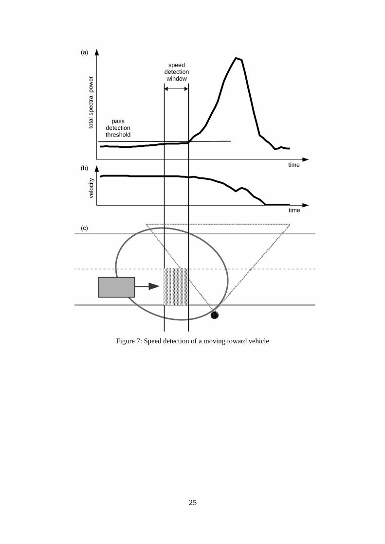
The same speed detection concepts are actual for the traffic case, when an object moves
toward the MWD sensor. There is a difference in the place of speed detection window,
it is located before the sharp rise in total spectral power caused by a passing vehicle.
This variant is depicted on Figure 7.
24
25
Figure 7: Speed detection of a moving toward vehicle
time
time
velo
city
tota
l spe
ctra
l pow
er
speed detection window
pass detection threshold
(a)
(c)
(b)
4 Distributed Tracking
What is the definition of distributed computing? Shortly, it is a way to solve difficult
tasks by applying multiple components united by a communication network, which is
used for coordination between separate units via messaging [14]. This kind of structure
allows to increase performance and improve scalability of systems, because all
components (individual devices equipped with its own processor and time counting
system) run concurrently and independently. In case of this research, a separate
component is the monitoring device, and a uniting network is provided by the radio
transceiver modules. Also, the tracking system uses the concepts of distributed
computing for improving energy efficiency and accuracy of calculations.
This section describes how the ideas of distributed computing are applied in this project.
First of all, a regular observable traffic case will be illustrated and investigated. Then,
the collaboration of the monitoring units will be explained in details, including a review
of necessary messages and all stages of the tracking algorithm. In the end of this section
the strategy of exceptional road events handling will be introduced as well.
4.1 Theory
According to [15], the most of WSN-based object tracking systems involves three major
components: a sensing subsystem, an estimation/prediction algorithm, and
a communication layer. This master thesis involves research, to varying degrees, about
all these approaches.
Commonly, it is envisioned, that every practical WSN joins hundreds and even
thousands of low-cost low-power monitoring devices, and has a self-organizing logical
structure [9]. There are a lot of approaches to unite nodes in a shared communication
space, reduce the amount of messaging and save extra energy [16]. Namely: sleep
scheduling, dynamic clustering and node selection. But these methods are out of scope
of this research. In the current work it is supposed to use a little predefined network,
26

which includes two tracking devices only. But that small network has a tremendous
potential to be integrated into a major sensor grid in the future.
The general purpose of the estimation/prediction algorithm is to provide an optimal
target tracking path, and one way to accomplish this is by enabling or disabling
particular sensor nodes at the right time [20]. The application of this scheme helps to
extremely reduce power consumption in large networks. In terms of this research the
tracking activation mechanism is also static. A monitoring node will send an activation
message to its single neighbour, when a vehicle is moving in the field of view of the
PIR sensor. It allows to manage the turn-on and turn-off time of the high energy-
consumption MWD sensors. So, each tracking device is a border point or a watchdog in
this case, and the sensor prediction problem is simplified [15].
The sensing in WSN can be carried out by two methods: single-node sensing and
collaborative sensing. The detailed description of the first one applied in this project is
introduced in section 3. The second subclass with distributed nature proposes to utilize
smart data processing via WSN. The major idea of collaborative signal processing
method is to use additional communication relations between specific tracking devices
for data aggregation [17] or compression [18]. This technique allows to optimize
information exchange in WSN and improve the quality of detection. The current
research applies the collaborative scheme to increase the precision of speed
measurement by sharing tracking data between separate devices.
In [19], the authors investigated and tested by simulation Selective Approach Algorithm
(SAA) for solving the moving target localization problem in WSN. The localization
problem is not directly related to speed measurements of moving single-objects, but it is
a very similar challenge, which asks the same questions to the accuracy of target
detection. SAA is a kind of estimation/prediction algorithm, which the researchers
proposed to save energy and improve quality of tracking. This algorithm contains the
similar ideas of cooperative sensing, which are applied in this thesis. The authors in [19]
deployed 100 virtual sensors with one mobile target randomly in the simulation and
launched the test. The verification results showed, that SAA is able to impressively
reduce power consumption and slightly improve the sensing precision of sensor
networks.
27

Also, authors in [20] proved, that using of joint sensing can significantly improve
information quality in WSN. They compared distributed sensing and individual sensing,
by simulation of a moving target alongside detection regions of eight ultrasonic sensors.
The basic idea behind joint sensing was to estimate target moving trajectory and predict,
which node should start object tracking at next time step. This experiment demonstrated
that, the joint sensing can increase the detection area, which means that a mobile target
is observable most part of the time. The number of simultaneous sensor measurements
was grown as well. This in turn allowed to aggregate multiple sensing data in fusion
centers and improve tracking accuracy in the end.
This work will go further from simulations and will demonstrate the effectiveness of
collaborative sensing by real experiment.
4.2 Tracking Session
Before starting to implement distributed computing algorithms, it will be a good idea to
analyze the steps of a vehicle moving through the deployed tracking system. A typical
ride consists of 3+2 stages by default. The full car trip, which is named as a tracking
session in this thesis, can be seen in Figure 8.
From this traffic case it is clear, what may be the meaning and exact limits of the
tracking session. A moving car is supposed to pass across all the detection zones of the
both monitoring devices in a predictable sequence, so it allows to define major steps and
the scope of tracking procedure. The tracking session will be started, if the PIR sensor
of the first unit generates a signal indicating movement, and will be finished, when the
PIR sensor of an opposite unit does the same thing (Figure 8b, Figure 8d). Between
these events a tracking mode is activated, and the MWD sensors are available to collect
motion live-data (Figure 8c).
28

The illustrated tracking session is repetitive and constant, so it gives a good start for
distributed system programming. First of all, it is necessary to formalize a general
tracking algorithm and reflect it into the activity diagram, which is presented on Figure
9. This diagram does not contain any details about communication or speed detection
process, but it shows major tracking steps, concurrent processes and most important
synchronization points. Figure 9 illustrates, that the activated tracking mode allows to
fuse the motion data from both monitoring units simultaneously in real time. This in
turn makes it possible to improve the quality of final assessment of vehicle speed.
Also, the illustrated traffic sequence demonstrates an opportunity to optimize energy
consumption. While a car is moving outside of the tracking system (Figure 8a, Figure
8e), there is no need to keep the MWD sensors turned on. For example, a power saving
mode may be activated at night, when traffic is sparse. The MWD sensors would sleep,
29
Figure 8: Tracking session traffic case
(a) Vehicle moves toward tracking system.
(b) Vehicle crosses the first PIR sensor detection zone. Session is started.
(c) Vehicle passes across MWD sensors tracking area. Session is active.
(d) Vehicle crosses the second PIR sensor detection zone. Session is finished.
(e) Vehicle moves away from tracking system.
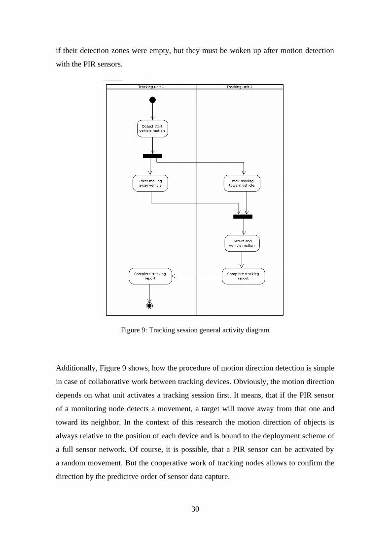
if their detection zones were empty, but they must be woken up after motion detection
with the PIR sensors.
Additionally, Figure 9 shows, how the procedure of motion direction detection is simple
in case of collaborative work between tracking devices. Obviously, the motion direction
depends on what unit activates a tracking session first. It means, that if the PIR sensor
of a monitoring node detects a movement, a target will move away from that one and
toward its neighbor. In the context of this research the motion direction of objects is
always relative to the position of each device and is bound to the deployment scheme of
a full sensor network. Of course, it is possible, that a PIR sensor can be activated by
a random movement. But the cooperative work of tracking nodes allows to confirm the
direction by the predicitve order of sensor data capture.
30
Figure 9: Tracking session general activity diagram

4.3 Collaboration
It is time to implement the details of collaboration between tracking units, but at the
beginning it will be useful to revise all data flows in the current tracking system. The
first data stream takes place inside the tracking unit, where MCU reads motion info
from sensors. The second data stream has the inherent nature of distributed systems –
message passing and receiving. The tracking session requires close cooperation between
monitoring devices, so each tracking unit needs to send regular messages with relevant
information to its partner. The data flow inside the tracking system is shown on Figure
10.
As can be seen from Figure 9, the scope of tracking sessions must be limited by two
different PIR sensors. So this circumstance leads to creation of two event messages: the
first one starts a tracking session, the second finishes it. The goal of these messages is
synchronizing of concurrent distributed computations. These events should be registered
in the right order and limited by valid time interval. Also, a collective tracking report is
required, so each unit has to share its own monitoring results with its partner. This
necessity adds at least two new messages to the interaction scheme of the tracking
system. These messages involve an average speed value provided by individual sensing
of a separate unit. This kind of information exchange is intended to improve the quality
of distributed computing.
After defining of the general tracking algorithm and all the needful messages, it
becomes feasible to implement the distributed tracking session in details. The sequence
31
Figure 10: Tracking system data flow diagram

diagram, which demonstrates all aspects of the tracking session, is illustrated on Figure
11. This diagram includes all the features listed in the background section of this thesis.
At the beginning the tracking system sleeps in power saving mode and its MWD
sensors are turned off. Then a moving car initialize the first step of a tracking session, at
32
Figure 11: Tracking session sequence diagram

the moment the PIR sensor of the first tracking unit registers the movement. This unit
immediately activates its own MWD sensor and sends the message to the opposite
partner with the command to start monitoring. The tracking partner turns on its
microwave radar, and the first tracking stage finishes at the point, where both units
observe their speed detection regions and the tracking session is started.
The second tracking step is about velocity estimation. In general, each separate unit
reads input raw data from its MWD sensor, processes that info and tries to detect valid
speed (the detailed explanation of this algorithm can be read in Section 3). This
operation repeats periodically until average car velocity is found by a unit, then the unit
sends a tracking summary to its partner. Every monitoring device executes the described
procedure independently and concurrently. At the end of the second step both tracking
units hold measured and received partner speeds and wait for an inevitable final event.
Of course, the correct order of speed detection reports should be verified at the end
of each tracking session.
Basically, the last tracking stage is the inversion of the first. The PIR sensor of the
second tracking unit generates the signal, that a car crosses its field of view. After that
the second unit finishes tracking, turns off its MWD sensor and notifies the partner
about this event. Then the opposite monitoring device does the same things.
Additionally, each unit updates its general tracking report before falling asleep.
4.4 Exceptions
Previously, the main ideas of the tracking session and comprehensive descriptions of
the distributed algorithm were explained in this section. But it is necessary to
emphasize, that all the mentioned concepts are valid for the ideal traffic case, which was
illustrated in Figure 8. Besides that case, a lot of other road situations are possible. For
example, city traffic may be heavy, or a car may stop between tracking units. These
events are depicted in Figure 12.
33

The one vehicle limitation was mentioned before and introduced on research purposes.
This restriction is very significant, and allows to track only a single moving car
at a time. Certainly, it is impossible to arrange urban traffic for academic needs, so the
exceptional situations must be handled. Because of the nature of the project, a chosen
strategy is simple – ignoring all unsuitable cases. It means, that the tracking system will
not try to continue monitoring, if something wrong happens, it will finnish an actual
session in that case. This proactive behaviour is provided by tracking timeouts and
smart managing of the PIR sensors.
However, the developed solution is tolerant to the lack of tracking information in those
cases, when one of the monitoring devices does not detect the vehicle’s speed.
Potentially, in real WSN these cases are supposed to be marked as partial in tracking
reports.
34
Figure 12: Tracking session exceptional traffic cases
(a) Many vehicles move through tracking zone simultaneously.
(b) Vehicle stops at the center of tracking zone.

5 Field Test
The introduced in section 4 distributed single-target tracking algorithm was
implemented using the special vehicle motion simulator and then tested in real road
conditions. This section gives an overview of field test setup and inputs. After that,
the test results will be compared with the current solution, and the analysis of those
outcomes will be divided into two parts: the accuracy of measurements and energy
consumption.
5.1 Setup
A testing place must correspond with couple of points:
• minimum traffic
• two poles are located on different sides of a road
According to these requirements the place was chosen in a silent part of Tallinn city
near the intersection of two roads: ‘Liivametsa tee’ and ‘Kalmistu tee’. Traffic is very
light in that spot, which allows to organize and fulfill testing without long delays.
The field test was carried out on Sunday, November 29, 2020.
The same scenario of sensor deployment, illustrated on Figure 5, was restored on
the chosen road segment. The distance between two suitable poles was 59 meters, and
tracking devices with corresponding firmware were attached to the poles at a height of
3 meters.
The main idea of the field test is to reproduce the five stages of tracking session,
described in section 4.2, with a particular car moving with known constant speed and
to collect some amount of tracking data. After that, it will be possible to compare those
logs with true observations and individual sensing solution. The implementation of all
those steps will allow to conclude – how efficient distributed computing is in this
35

specific case? The data relevant for analyzing the results of the experiment was
collected via a base station, that receives log data directly from the sensors over the
wireless connection.
5.2 Accuracy of Speed detection
For better verification of tracking results the test involved measurements of two
different speeds: 50 km/h and 30 km/h. That specific speeds were chosen, as they are
the most popular in urban areas. Single-node sensing speed measurements were
provided by the current monitoring solution deployed in the SmENeTe2 network today.
The comparison of those outcomes shows the profit from the integration of
collaborative sensing into the network. The raw test results of speed detection of
a moving vehicle at speed ~50 km/h are given in Table 1.
Single-node Sensing Collaborative Sensing
Car speedometer ~50 km/hGPS speedometer ~46 km/h
43,838,740,636,842,529,832,442,535,537,441,238,719,624,143,242,5
Average: 36,83
node 1 node 2
39.325 —› 41.358 45.360 —› 44.400 45.678 —› 45.18543.708 —› 43.51845.169 —› 45.529
Table 1: Field test results of 50 km/h speed detection
On the left side of the table are listed the data generated by individual sensing mode.
Each row corresponds to a detected speed per one passed vehicle. On the right side of
36
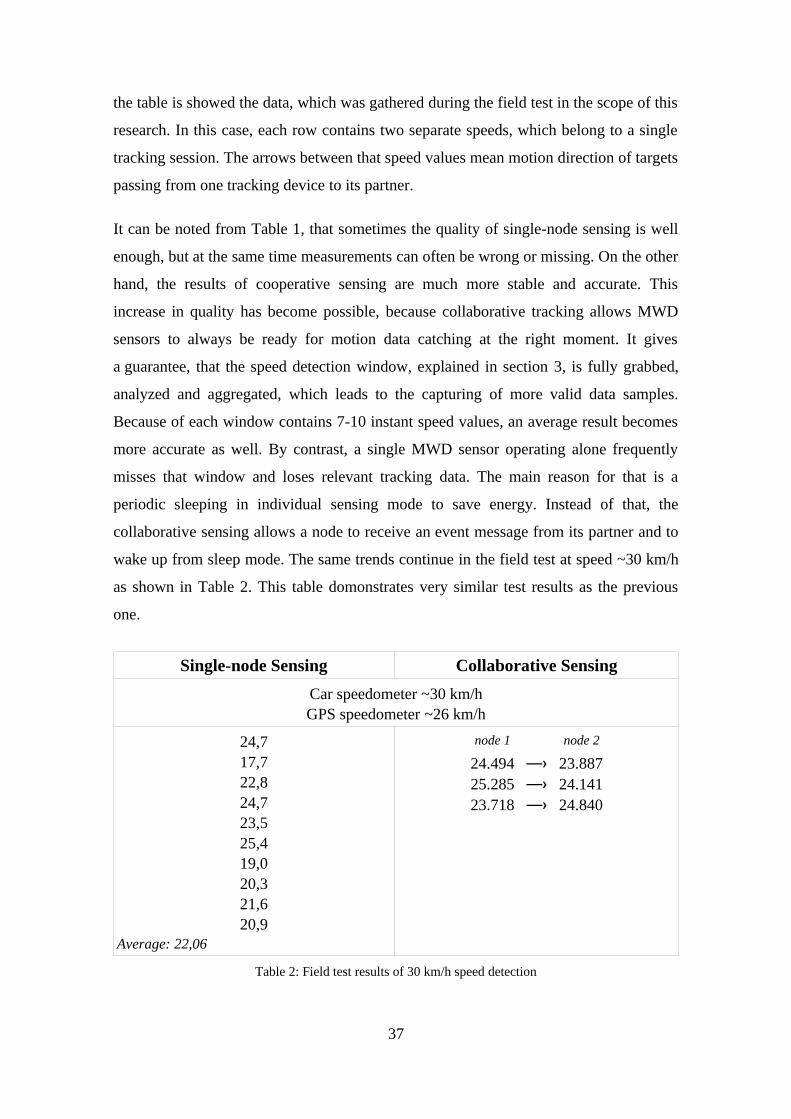
the table is showed the data, which was gathered during the field test in the scope of this
research. In this case, each row contains two separate speeds, which belong to a single
tracking session. The arrows between that speed values mean motion direction of targets
passing from one tracking device to its partner.
It can be noted from Table 1, that sometimes the quality of single-node sensing is well
enough, but at the same time measurements can often be wrong or missing. On the other
hand, the results of cooperative sensing are much more stable and accurate. This
increase in quality has become possible, because collaborative tracking allows MWD
sensors to always be ready for motion data catching at the right moment. It gives
a guarantee, that the speed detection window, explained in section 3, is fully grabbed,
analyzed and aggregated, which leads to the capturing of more valid data samples.
Because of each window contains 7-10 instant speed values, an average result becomes
more accurate as well. By contrast, a single MWD sensor operating alone frequently
misses that window and loses relevant tracking data. The main reason for that is a
periodic sleeping in individual sensing mode to save energy. Instead of that, the
collaborative sensing allows a node to receive an event message from its partner and to
wake up from sleep mode. The same trends continue in the field test at speed ~30 km/h
as shown in Table 2. This table domonstrates very similar test results as the previous
one.
Single-node Sensing Collaborative Sensing
Car speedometer ~30 km/hGPS speedometer ~26 km/h
24,717,722,824,723,525,419,020,321,620,9
Average: 22,06
node 1 node 2
24.494 —› 23.88725.285 —› 24.141 23.718 —› 24.840
Table 2: Field test results of 30 km/h speed detection
37
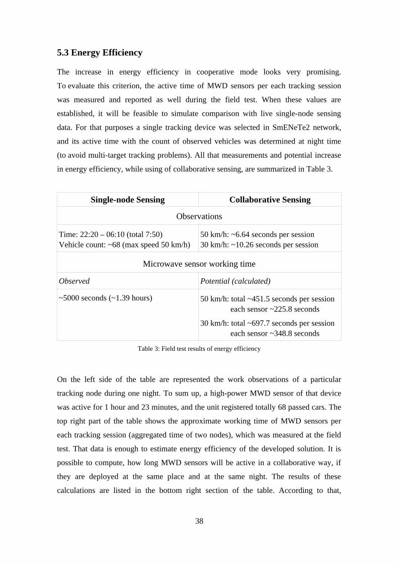
5.3 Energy Efficiency
The increase in energy efficiency in cooperative mode looks very promising.
To evaluate this criterion, the active time of MWD sensors per each tracking session
was measured and reported as well during the field test. When these values are
established, it will be feasible to simulate comparison with live single-node sensing
data. For that purposes a single tracking device was selected in SmENeTe2 network,
and its active time with the count of observed vehicles was determined at night time
(to avoid multi-target tracking problems). All that measurements and potential increase
in energy efficiency, while using of collaborative sensing, are summarized in Table 3.
Single-node Sensing Collaborative Sensing
Observations
Time: 22:20 – 06:10 (total 7:50)Vehicle count: ~68 (max speed 50 km/h)
50 km/h: ~6.64 seconds per session30 km/h: ~10.26 seconds per session
Microwave sensor working time
Observed Potential (calculated)
~5000 seconds (~1.39 hours) 50 km/h: total ~451.5 seconds per session each sensor ~225.8 seconds
30 km/h: total ~697.7 seconds per session each sensor ~348.8 seconds
Table 3: Field test results of energy efficiency
On the left side of the table are represented the work observations of a particular
tracking node during one night. To sum up, a high-power MWD sensor of that device
was active for 1 hour and 23 minutes, and the unit registered totally 68 passed cars. The
top right part of the table shows the approximate working time of MWD sensors per
each tracking session (aggregated time of two nodes), which was measured at the field
test. That data is enough to estimate energy efficiency of the developed solution. It is
possible to compute, how long MWD sensors will be active in a collaborative way, if
they are deployed at the same place and at the same night. The results of these
calculations are listed in the bottom right section of the table. According to that,
38

potentially the energy consumption of MWD sensors can be reduced by nearly 86-95%
(rough comparison of minimum and maximum computed times with real measured
time).
39

6 Summary
This research focused on actual challenges of smart cities, especially on the problems
related with traffic monitoring systems. The traffic sensor network developed during
the SmENeTe2 project was chosen as the main object of study in this thesis. It is a
cluster of low-cost sensor modules deployed in Tallinn city and united in WSN. The
major purposes of this investigation were to improve the accuracy of speed estimation
and solve energy shortage of the traffic sensor devices. As a possible solution this
research proposed to integrate a collaborative tracking approach into that network and
explored the potential of that improvement in practice.
To test that hypothesis, an existing codebase was studied and necessary parts of
software were implemented in C programming language with using of some additional
beneficial libraries for embedded development. The conclusions about effectiveness of
distributed target tracking concepts were based on a series of field tests, where
experimental firmware were deployed to two monitoring nodes and tested in real road
conditions. From these experiments it was found out, that the theory was confirmed by
practice.
The verification tests showed, that the adding of basic distributed computing techniques
to a network with just two nodes can significantly improve critical characteristics and
properties of that system. The experiment proved, that the integration of simple tracking
activation mechanism, which was provided by PIR sensors on the borders of monitored
areas, was able to reduce active time of high-power sensors more than tenfold.
Potentially, the applying of that feature to larger networks can extremely improve
energy saving aspects of each tracking node. At the same time, that mechanism
influenced on the quality of speed detection in positive way. This research proved, that
cooperative sensing increases the reliability and stability of measurements. The field test
showed, that the final speed data became much more regular and precise in all cases.
Also in perspective, cooperative target tracking can palpably optimize information
exchange inside large WSN by reducing the number of messages.
40

Definitely, the results of this work can be applied to any target tracking WSN, where
data quality and energy efficiency is an important point. In the context of
the SmENeTe2 project this research can be used to improve monitoring functions of
microwave radar sensors and microphone array sensor as well. Also, adding of
the described collaboration method into the entire SmENeTe2 wireless network could
even solve the problem of power supply in wintertime.
6.1 Future Work
Of course, this research was only the first step in the collaborative target tracking field.
This work focused only on single-target tracking solution, which can be used on the
roads, where traffic density is low, or at night time. Unfortunately, it is inapplicable to
places with heavy traffic. The multi-target tracking problem is a much more serious and
ambitious challenge, but it could take the monitoring system to the next level. There is
necessary to have deep knowledges about detection algorithms, and a communication
layer needs to be involved in the tracking process as well.
Continuous tracking of a moving object through a larger network is another interesting
question, which also was not covered by this research. A working solution, which
breaks that problem, could bring a lot of additional dynamic information about a
moving object. That kind of research will require to develop an advanced and
complicated prediction algorithm and well-organized logical network structure.
41

References
[1] Klk Vito Albino, Umberto Berardi, Rosa Maria Dangelico, “Smart Cities: Definitions, Dimensions, Performance, and Initiatives”, 2015.
[2] The British Standards Institution, “BSI Standards Publication. Smart cities – Vocabulary”, pp. 1-4, 2014.
[3] Didier El Baz, Julien Bourgeois, “Smart Cities in Europe and the ALMA Logistics Project”, pp. 10-13, 2015.
[4] Allan M de Souza, Celso ARL Brennand, Roberto S Yokoyama, Erick A Donato, Edmundo RM Madeira, Leandro A Villas, “Traffic management systems: A classification, review, challenges, and future perspectives”, 2016.
[5] Giordano, Nicholas ,“College Physics: Reasoning and Relationships”, pp. 421–424, 2009.
[6] James K. Peckol, “Embedded Systems: A Contemporary Design Tool, Second Edition”, pp. 541-625, 2019.
[7] Anis KOUBAA, Mário ALVES, Eduardo TOVAR, “IEEE 802.15.4 for Wireless Sensor Networks: A Technical Overview”, 2005.
[8] Bracewell, R. “The Fourier Transform and Its Applications, 3rd edition”, 1999.
[9] I. Akyildiz, W. Su, Y. Sankarasubramaniam, and E. Cayirci, “Wireless sensor networks: asurvey,” Computer networks, vol. 38, no. 4, pp. 393–422, 2002.
[10] Lucia Keleadile Ketshabetswe, Adamu Murtala Zungeru, Mmoloki Mangwala, Joseph M.Chuma, Boyce Sigweni, “Communication protocols for wireless sensor networks: survey and comparison.”, 2019.
[11] “Smart Environment Networking Technologies”, https://www.etis.ee/Portal/Projects/Display/524915ce-7aa5-43a2-9463-7d519689ef5b (last visited on 2021-01-09)
[12] “Intelligent Smart City and Critical Infrastructure Protection Technologies ISC2PT II”, https://www.etis.ee/Portal/Projects/Display/96569b7f-a42a-422f-bd8f-97cbb3a483b1 (last visited on 2021-01-09)
[13] Andri Riid, Jaanus Kaugerand, Johannes Ehala, Martin Jaanus, Jürgo-Sören Preden, “An Application of a Low-Cost Microwave Radar to Traffic Monitoring”, 2018.
[14] Maarten van Steen, Andrew S. Tanenbaum, “Distributed Systems. Third edition”, pp. 1-2,2018.
[15] Oualid Demigha, Walid-Khaled Hidouci, Toufik Ahmed, “On Energy Efficiency in Collaborative Target Tracking in Wireless Sensor Network: A Review”, 2012.
42

[16] Guorui Li, Haobo Chen, Sancheng Peng, Xinguang Li, Cong Wang, Shui Yu, Pengfei Yin, “A Collaborative Data Collection Scheme Based on Optimal Clustering for WirelessSensor Networks”, 2018.
[17] R. Rajagopalan, P. Varshney, “Data-aggregation techniques in sensor networks: a survey”, 2006.
[18] J. Qiao, X. Zhang, “Compressive Data Gathering Based on Even Clustering for Wireless Sensor Networks”, 2018.
[19] Z.Mary Livisna, S.Jayashri, “Moving target localization in WSNS”, 2015.
[20] W. Xiao, C. K. Tham, S. K. Das, “Collaborative Sensing to Improve Information Quality for Target Tracking in Wireless Sensor Networks”, 2010.
43

Appendix 1 – Non-exclusive licence for reproduction and
publication of a graduation thesis1
I German Mundinger
1 Grant Tallinn University of Technology free licence (non-exclusive licence) for my
thesis “Energy Efficient Collaborative Single-Target Tracking in Wireless Sensor
Network with Low Power Microwave Radar Sensors”, supervised by
Jaanus Kaugerand and Raido Pahtma
1.1 to be reproduced for the purposes of preservation and electronic publication of
the graduation thesis, incl. to be entered in the digital collection of the library of
Tallinn University of Technology until expiry of the term of copyright;
1.2 to be published via the web of Tallinn University of Technology, incl. to be
entered in the digital collection of the library of Tallinn University of
Technology until expiry of the term of copyright.
2 I am aware that the author also retains the rights specified in clause 1 of the non-
exclusive licence.
3 I confirm that granting the non-exclusive licence does not infringe other persons'
intellectual property rights, the rights arising from the Personal Data Protection Act
or rights arising from other legislation.
11.01.2021
1 The non-exclusive licence is not valid during the validity of access restriction indicated in the student'sapplication for restriction on access to the graduation thesis that has been signed by the school's dean, except in case of the university's right to reproduce the thesis for preservation purposes only. If a graduation thesis is based on the joint creative activity of two or more persons and the co-author(s) has/have not granted, by the set deadline, the student defending his/her graduation thesis consent to reproduce and publish the graduation thesis in compliance with clauses 1.1 and 1.2 of the non-exclusive licence, the non-exclusive license shall not be valid for the period.
44

Appendix 2 – Software Project for Collaborative Tracking
The source code with implemented features, which were introduced in this thesis, can
be found on:
https://github.com/germandevelop/node-apps
This project was forked from a training project for some SiLabs based devices with
simple example applications. The developed application can be compiled for the using
with a particular vehicle motion simulator, but for the deployment to a real tracking
device as well. Also, this project contains a lot of unit tests and test cases for the
simulator.
45