energy-efficient faÇade solutions from a single source
TRANSCRIPT

ENERGY-EFFICIENT FAÇADE SOLUTIONS FROM A SINGLE SOURCE
Two specialists have joined forces to offer a unique substructure for your individual rainscreen cladding façade (RCF) designs

5
6
7
8
Fitting Page 18
Climate protection Page 19
Our service Page 20
1
2
3
4
Benefits of RCF Page 4
RCF with no thermal bridges Page 7
Typical façade systems Page 8
Energy-efficient product components Page 14
Construction physics Page 16
Applications Page 10
9
Image sources: Page 3: HEUWIESER Metalltechnik GmbH; Page 5: ALU-BAU Gräbner GmbH; Page 6: ALU-BAU Gräbner GmbH; Page 9: AS Fassaden; Page 10: maximilian gottwald; Page 11: AS Fassaden; Page 12: AS Fassaden; Page 13: AS Fassaden; Page 15: Fiberline Composites A/S
Combined expertise for a free and energy-efficient design
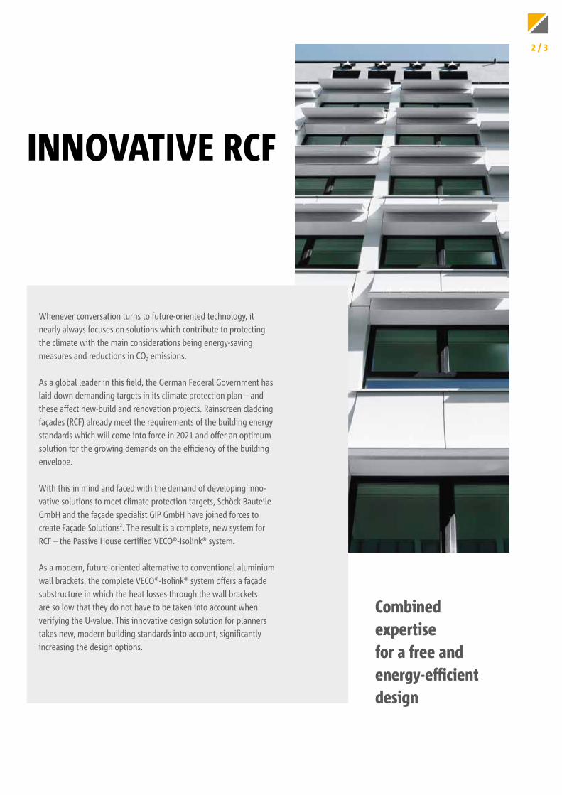
INNOVATIVE RCF
Whenever conversation turns to future-oriented technology, it nearly always focuses on solutions which contribute to protecting the climate with the main considerations being energy-saving measures and reductions in CO2 emissions.
As a global leader in this field, the German Federal Government has laid down demanding targets in its climate protection plan – and these affect new-build and renovation projects. Rainscreen cladding façades (RCF) already meet the requirements of the building energy standards which will come into force in 2021 and offer an optimum solution for the growing demands on the efficiency of the building envelope.
With this in mind and faced with the demand of developing inno-vative solutions to meet climate protection targets, Schöck Bauteile GmbH and the façade specialist GIP GmbH have joined forces to create Façade Solutions2. The result is a complete, new system for RCF – the Passive House certified VECO®-Isolink® system.
As a modern, future-oriented alternative to conventional aluminium wall brackets, the complete VECO®-Isolink® system offers a façade substructure in which the heat losses through the wall brackets are so low that they do not have to be taken into account when verifying the U-value. This innovative design solution for planners takes new, modern building standards into account, significantly increasing the design options.
2 / 3
CONVINCING BENEFITS
1
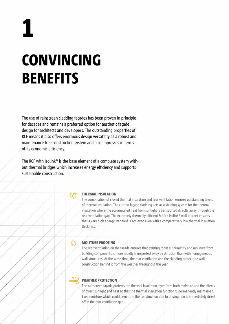
The use of rainscreen cladding façades has been proven in principle for decades and remains a preferred option for aesthetic façade design for architects and developers. The outstanding properties of RCF means it also offers enormous design versatility as a robust and maintenance-free construction system and also impresses in terms of its economic efficiency.
The RCF with Isolink® is the base element of a complete system with-out thermal bridges which increases energy efficiency and supports sustainable construction.
THERMAL INSULATIONThe combination of closed thermal insulation and rear ventilation ensures outstanding levels of thermal insulation. The curtain façade cladding acts as a shading system for the thermal insulation where the accumulated heat from sunlight is transported directly away through the rear ventilation gap. The extremely thermally efficient Schöck Isolink® wall bracket ensures that a very high energy standard is achieved even with a comparatively low thermal insulation thickness.
MOISTURE PROOFINGThe rear ventilation on the façade ensures that existing room air humidity and moisture from building components is more rapidly transported away by diffusion than with homogeneous wall structures. At the same time, the rear ventilation and the cladding protect the wall construction behind it from the weather throughout the year.
WEATHER PROTECTIONThe rainscreen façade protects the thermal insulation layer from both moisture and the effects of direct sunlight and heat so that the thermal insulation function is permanently maintained. Even moisture which could penetrate the construction due to driving rain is immediately dried off in the rear ventilation gap.
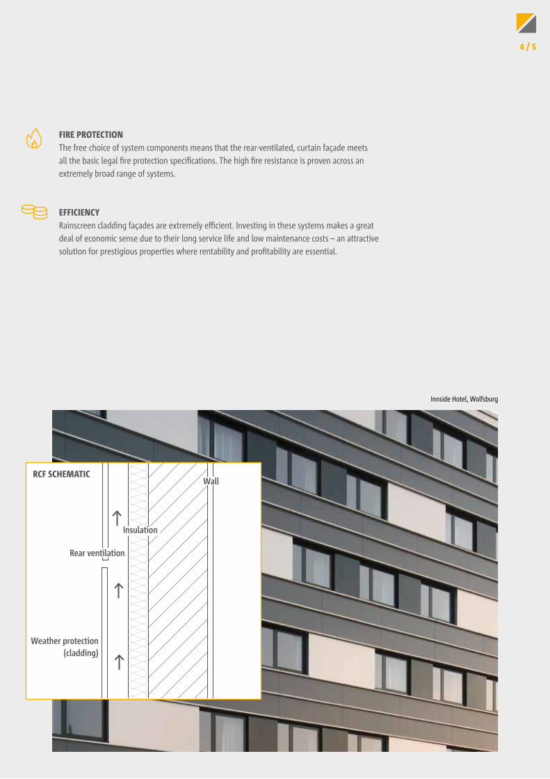
RCF SCHEMATIC
Weather protection(cladding)
Wall
Insulation
Rear ventilation
FIRE PROTECTIONThe free choice of system components means that the rear-ventilated, curtain façade meets all the basic legal fire protection specifications. The high fire resistance is proven across an extremely broad range of systems.
EFFICIENCYRainscreen cladding façades are extremely efficient. Investing in these systems makes a great deal of economic sense due to their long service life and low maintenance costs – an attractive solution for prestigious properties where rentability and profitability are essential.
Innside Hotel, Wolfsburg
4 / 5
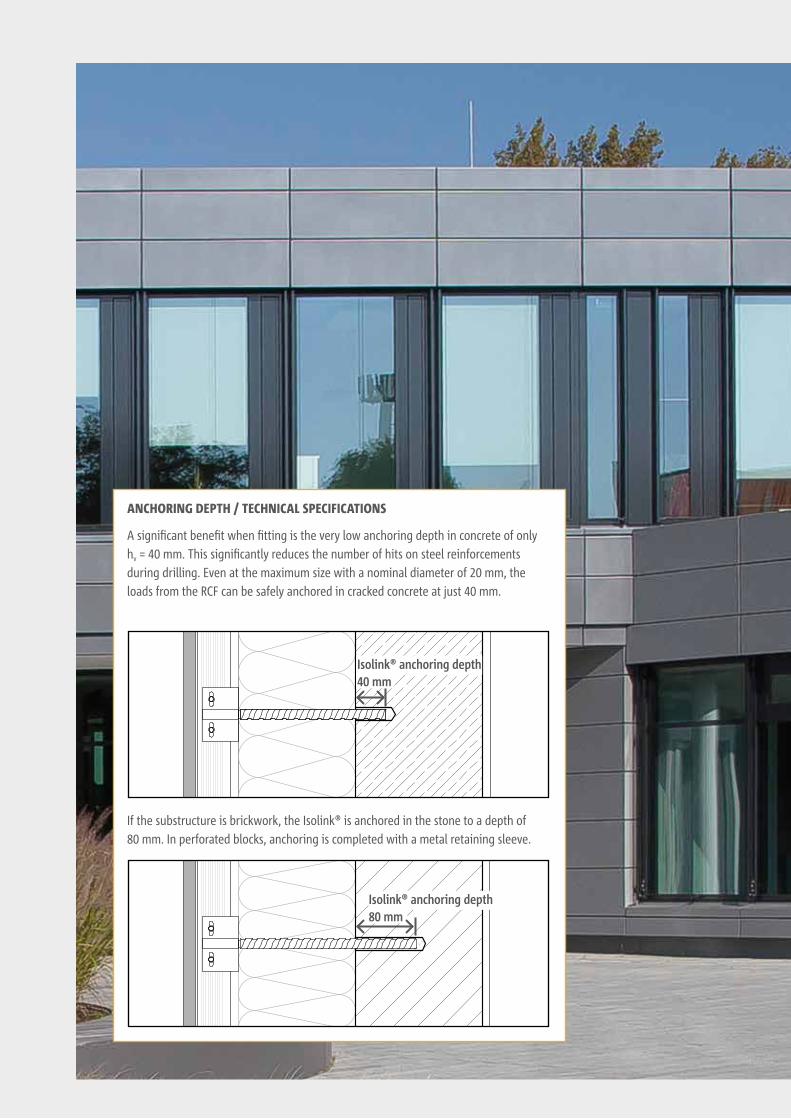
Isolink® anchoring depth40 mm
Isolink® anchoring depth80 mm
A significant benefit when fitting is the very low anchoring depth in concrete of only hv = 40 mm. This significantly reduces the number of hits on steel reinforcements during drilling. Even at the maximum size with a nominal diameter of 20 mm, the loads from the RCF can be safely anchored in cracked concrete at just 40 mm.
If the substructure is brickwork, the Isolink® is anchored in the stone to a depth of 80 mm. In perforated blocks, anchoring is completed with a metal retaining sleeve.
ANCHORING DEPTH / TECHNICAL SPECIFICATIONS
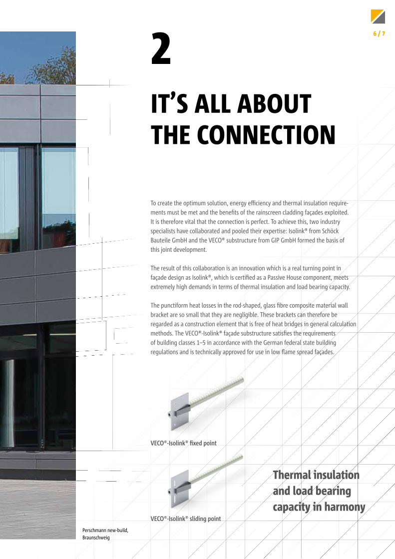
To create the optimum solution, energy efficiency and thermal insulation require-ments must be met and the benefits of the rainscreen cladding façades exploited. It is therefore vital that the connection is perfect. To achieve this, two industry specialists have collaborated and pooled their expertise: Isolink® from Schöck Bauteile GmbH and the VECO® substructure from GIP GmbH formed the basis of this joint development. The result of this collaboration is an innovation which is a real turning point in façade design as Isolink®, which is certified as a Passive House component, meets extremely high demands in terms of thermal insulation and load bearing capacity.
The punctiform heat losses in the rod-shaped, glass fibre composite material wall bracket are so small that they are negligible. These brackets can therefore be regarded as a construction element that is free of heat bridges in general calculation methods. The VECO®-Isolink® façade substructure satisfies the requirements of building classes 1–5 in accordance with the German federal state building regulations and is technically approved for use in low flame spread façades.
IT’S ALL ABOUT THE CONNECTION
2
Thermal insulation and load bearing capacity in harmony
VECO®-Isolink® fixed point
VECO®-Isolink® sliding point
Perschmann new-build, Braunschweig
6 / 7
A UNIQUE SOLUTION FOR NEW BUILDINGS AND RENOVATION PROJECTS
3
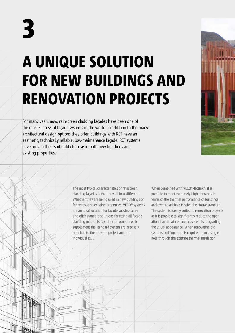
For many years now, rainscreen cladding façades have been one of the most successful façade systems in the world. In addition to the many architectural design options they offer, buildings with RCF have an aesthetic, technically reliable, low-maintenance façade. RCF systems have proven their suitability for use in both new buildings and existing properties.
The most typical characteristics of rainscreen cladding façades is that they all look different. Whether they are being used in new buildings or for renovating existing properties, VECO® systems are an ideal solution for façade substructures and offer standard solutions for fixing all façade cladding materials. Special components which supplement the standard system are precisely matched to the relevant project and the individual RCF.
When combined with VECO®-Isolink®, it is possible to meet extremely high demands in terms of the thermal performance of buildings and even to achieve Passive the House standard. The system is ideally suited to renovation projects as it is possible to significantly reduce the oper-ational and maintenance costs whilst upgrading the visual appearance. When renovating old systems nothing more is required than a single hole through the existing thermal insulation.
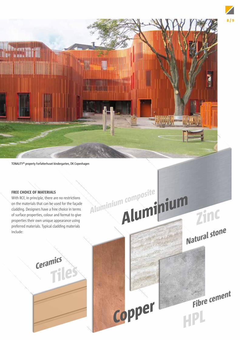
FREE CHOICE OF MATERIALSWith RCF, in principle, there are no restrictions on the materials that can be used for the façade cladding. Designers have a free choice in terms of surface properties, colour and format to give properties their own unique appearance using preferred materials. Typical cladding materials include:
HPL
Ceramics
Aluminium composite
Fibre cement
Natural stoneAluminium
Copper
Tiles
Zinc
TONALITY® property Forfatterhuset kindergarten, DK Copenhagen
8 / 9
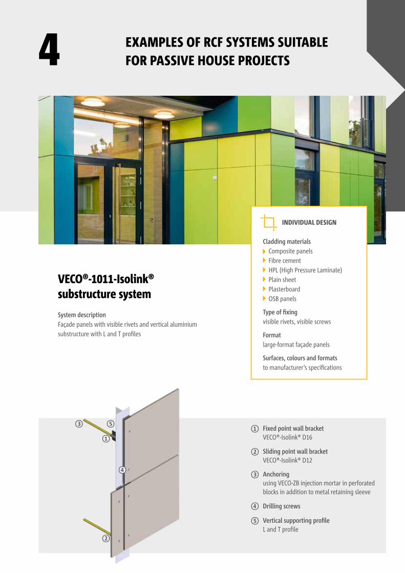
VECO®-1011-Isolink® substructure system
System descriptionFaçade panels with visible rivets and vertical aluminium substructure with L and T profiles
INDIVIDUAL DESIGN
Cladding materials Composite panels Fibre cement HPL (High Pressure Laminate) Plain sheet Plasterboard OSB panels
Type of fixingvisible rivets, visible screws
Formatlarge-format façade panels
Surfaces, colours and formatsto manufacturer’s specifications
Fixed point wall bracket VECO®-Isolink® D16
Sliding point wall bracket VECO®-Isolink® D12
Anchoring using VECO-ZB injection mortar in perforated blocks in addition to metal retaining sleeve
Drilling screws
4 EXAMPLES OF RCF SYSTEMS SUITABLE FOR PASSIVE HOUSE PROJECTS
Vertical supporting profileL and T profile
①①
④
②
③ ⑤
②
③
④
⑤
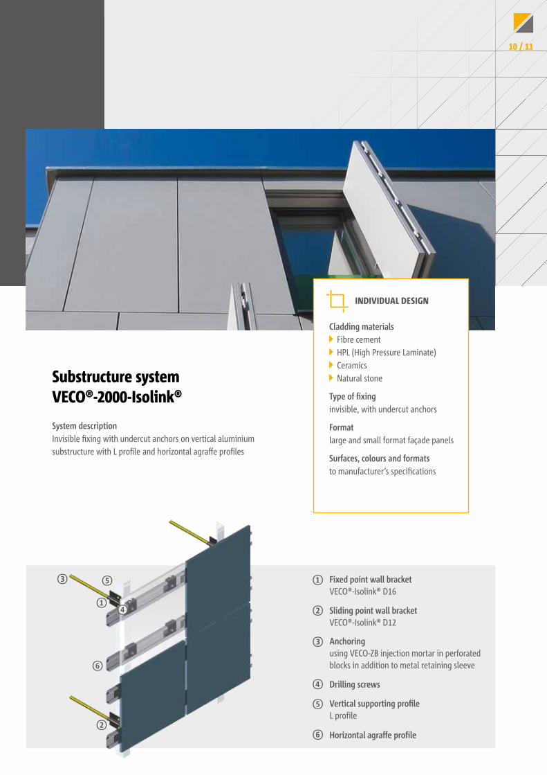
Substructure system VECO®-2000-Isolink®
System descriptionInvisible fixing with undercut anchors on vertical aluminium substructure with L profile and horizontal agraffe profiles
INDIVIDUAL DESIGN
Cladding materials Fibre cement HPL (High Pressure Laminate) Ceramics Natural stone
Type of fixinginvisible, with undercut anchors
Formatlarge and small format façade panels
Surfaces, colours and formatsto manufacturer’s specifications
Fixed point wall bracket VECO®-Isolink® D16
Sliding point wall bracket VECO®-Isolink® D12
Anchoring using VECO-ZB injection mortar in perforated blocks in addition to metal retaining sleeve
Drilling screws
Vertical supporting profileL profile
Horizontal agraffe profile
①
②
③
④
⑤
⑥
①④
②
⑥
③ ⑤
10 / 11
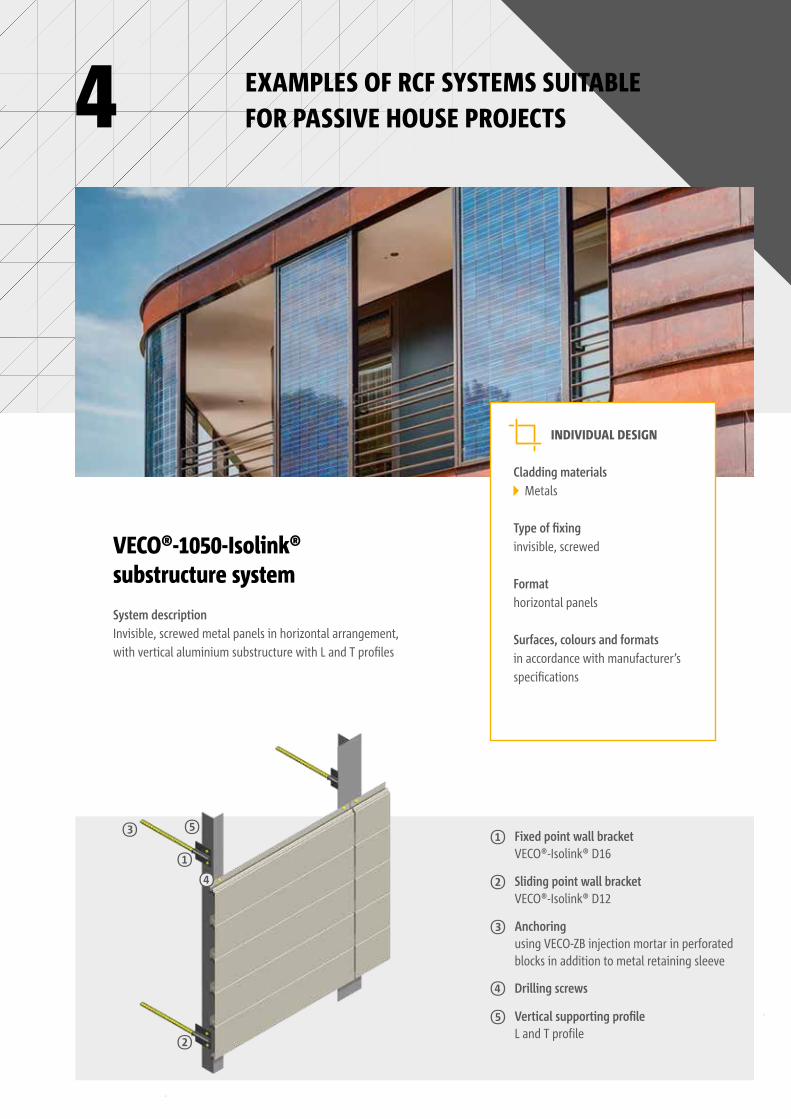
VECO®-1050-Isolink® substructure systemSystem descriptionInvisible, screwed metal panels in horizontal arrangement, with vertical aluminium substructure with L and T profiles
INDIVIDUAL DESIGN
Cladding materials Metals
Type of fixinginvisible, screwed
Formathorizontal panels
Surfaces, colours and formats in accordance with manufacturer’s specifications
4
Fixed point wall bracket VECO®-Isolink® D16
Sliding point wall bracket VECO®-Isolink® D12
Anchoring using VECO-ZB injection mortar in perforated blocks in addition to metal retaining sleeve
Drilling screws
Vertical supporting profileL and T profile
EXAMPLES OF RCF SYSTEMS SUITABLE FOR PASSIVE HOUSE PROJECTS
①
②
③
④
⑤
①④
②
③ ⑤
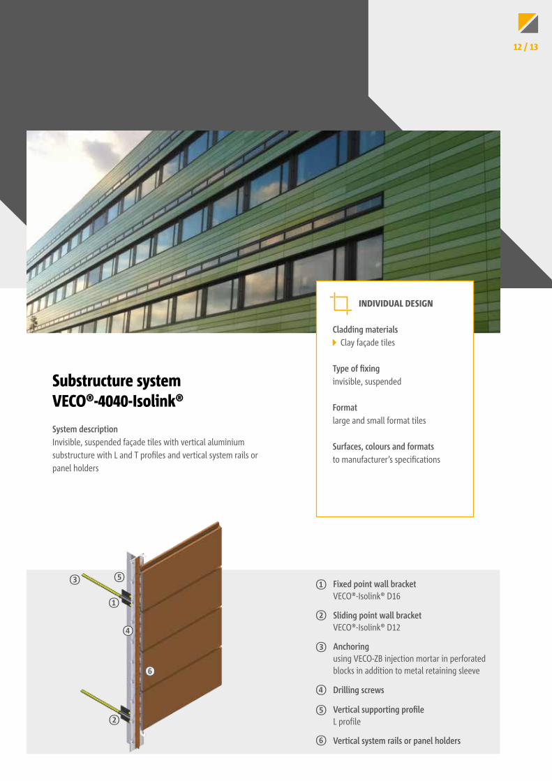
Substructure system VECO®-4040-Isolink®System descriptionInvisible, suspended façade tiles with vertical aluminium substructure with L and T profiles and vertical system rails or panel holders
INDIVIDUAL DESIGN
Cladding materials Clay façade tiles
Type of fixinginvisible, suspended
Formatlarge and small format tiles
Surfaces, colours and formatsto manufacturer’s specifications
Vertical system rails or panel holders
Fixed point wall bracket VECO®-Isolink® D16
Sliding point wall bracket VECO®-Isolink® D12
Anchoring using VECO-ZB injection mortar in perforated blocks in addition to metal retaining sleeve
Drilling screws
Vertical supporting profileL profile
①
②
③
④
⑤
⑥
①
④
②
⑥
③ ⑤
12 / 13
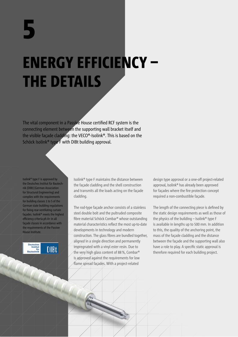
ENERGY EFFICIENCY – THE DETAILS
5
The vital component in a Passive House certified RCF system is the connecting element between the supporting wall bracket itself and the visible façade cladding: the VECO®-Isolink®. This is based on the Schöck Isolink® type F with DIBt building approval.
Isolink® type F maintains the distance between the façade cladding and the shell construction and transmits all the loads acting on the façade cladding.
The rod-type façade anchor consists of a stainless steel double bolt and the pultruded composite fibre material Schöck Combar® whose outstanding material characteristics reflect the most up-to-date developments in technology and modern construction. The glass fibres are bundled to gether, aligned in a single direction and permanently impregnated with a vinyl ester resin. Due to the very high glass content of 88 %, Combar® is approved against the requirements for low flame spread façades. With a project-related
design type approval or a one-off project-related approval, Isolink® has already been approved for façades where the fire protection concept required a non-combustible façade.
The length of the connecting piece is defined by the static design requirements as well as those of the physics of the building – Isolink® type F is available in lengths up to 500 mm. In addition to this, the quality of the anchoring point, the mass of the façade cladding and the distance between the façade and the supporting wall also have a role to play. A specific static approval is therefore required for each building project.
Isolink® type F is approved by the Deutsches Institut für Bau tech-nik (DIBt) (German Association for Structural Engineering) and complies with the requirements for building classes 1 to 5 of the German state building regulations for fixing rear-ventilating curtain façades. Isolink® meets the highest efficiency criteria ph A+ in all façade classes in accordance with the requirements of the Passive House Institute.
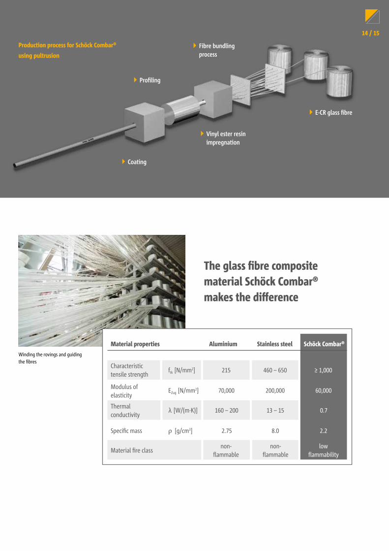
Production process for Schöck Combar®
using pultrusion
Profiling
Fibre bundling process
Coating
E-CR glass fibre
Vinyl ester resin impregnation
The glass fibre composite material Schöck Combar® makes the difference
Winding the rovings and guiding the fibres
60,000
2.2
≥ 1,000
0.7
low flammability
Material properties Aluminium Stainless steel Schöck Combar®
Modulus of elasticity
Specific mass
EZug [N/mm2]
ρ [g/cm3]
ftk [N/mm2]Characteristic tensile strength
Thermal conductivity
λ [W/(m·K)]
Material fire class
70,000
2.75
200,000
8.0
215 460 – 650
160 – 200 13 – 15
non-flammable
non-flammable
14 / 15
FACTS PROVIDE CERTAINTY
6
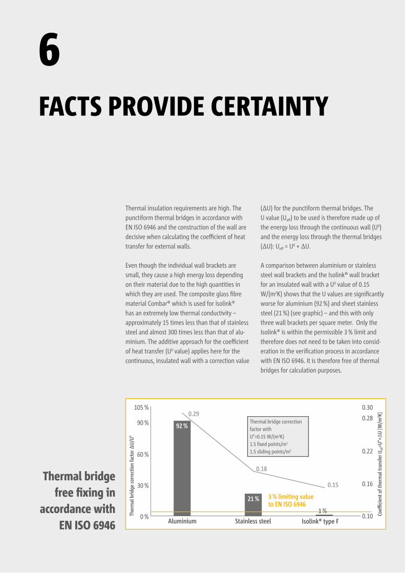
Thermal insulation requirements are high. The punctiform thermal bridges in accordance with EN ISO 6946 and the construction of the wall are decisive when calculating the coefficient of heat transfer for external walls.
Even though the individual wall brackets are small, they cause a high energy loss depending on their material due to the high quantities in which they are used. The composite glass fibre material Combar® which is used for Isolink® has an extremely low thermal conductivity – approximately 15 times less than that of stainless steel and almost 300 times less than that of alu-minium. The additive approach for the coefficient of heat transfer (U0 value) applies here for the continuous, insulated wall with a correction value
(ΔU) for the punctiform thermal bridges. The U value (Ueff) to be used is therefore made up of the energy loss through the continuous wall (U0) and the energy loss through the thermal bridges (ΔU): Ueff = U0 + ΔU.
A comparison between aluminium or stainless steel wall brackets and the Isolink® wall bracket for an insulated wall with a U0 value of 0.15 W/(m2K) shows that the U values are significantly worse for aluminium (92 %) and sheet stainless steel (21 %) (see graphic) – and this with only three wall brackets per square meter. Only the Isolink® is within the permissible 3 % limit and therefore does not need to be taken into consid-eration in the verification process in accordance with EN ISO 6946. It is therefore free of thermal bridges for calculation purposes.
Ther
mal
brid
ge co
rrect
ion
fact
or ∆
U/U°
Aluminium Stainless steel0 %
30 %
60 %
90 %
105 %
Coeffi
cient
of t
herm
al tr
ansf
er U
eff=U
°+Δ
U [W
/m2 K]
Isolink® type F
92 %
0.29
0.18
0.15
21 % 3 % limiting valueto EN ISO 6946
0.10
0.16
0.22
0.28
0.30
Thermal bridge correction factor withU°=0.15 W/(m2K)1.5 fixed points/m2
1.5 sliding points/m2
1 %
Thermal bridge free fixing in
accordance with EN ISO 6946
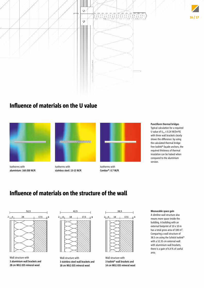
Punctiform thermal bridges Typical calculation for a required U value of Uerf ≤ 0.24 W/(m2K) with three wall brackets clearly shows the difference: by using the calculated thermal bridge free Isolink® façade anchors, the required thickness of thermal insulation can be halved when compared to the aluminium version.
Measurable space gainA slimline wall structure also means more space inside the building. A building with an external footprint of 10 x 10 m has a total gross area of 100 m². Comparing a wall structure of 38.5 cm using the Schöck Isolink® with a 52.35 cm external wall with aluminium wall brackets, there is a gain of 6.4 % of useful area.
Isotherms with stainless steel: 13-15 W/K
Isotherms with aluminium: 160-200 W/K
Isotherms with Combar®: 0.7 W/K
Wall structure with 3 stainless steel wall brackets and 18 cm WLG 035 mineral wool
Wall structure with 3 Isolink® wall brackets and 14 cm WLG 035 mineral wool
Wall structure with 3 aluminium wall brackets and28 cm WLG 035 mineral wool
Influence of materials on the U value
Influence of materials on the structure of the wall
16 / 17
OKFFB
5
+21.84
.600
.500
.150
.250
.876
+18.05
+17.85
OKFFB±0.00
.600
.900
.292
.008
.892
.210
.350
.300
.350
.130
.600
.254
.130
.200
.012
.700
.400
.700
.026
.023.01
2
.301
.495
.495
.210
.008
1.192
.292
.008
.008
.592
.308
1.200
.300
.008
2.500
.013
.036
UK ROHDECKE
OKFFB
5
+0.08
OKFFB+0.10
OKFFB+0.11
OKFFB+0.22
.160
.250
+6.65
UK ROHDECKE
+6.65
UK FERTIGDECKE
+6.39
UK ROHDECKE
+6.13
UK FERTIGDECKE
OKFFB
3
-0.26
OKFFB
3
-0.41
-0.35
UK ROHDECKE
-0.415
UK FERTIGDECKE
-0.943
UK ROHDECKE
-1.008
UK FERTIGDECKE
.065
FASSADENDETAIL-11 - VERTIKALSCHNITT B-B - M 1:10
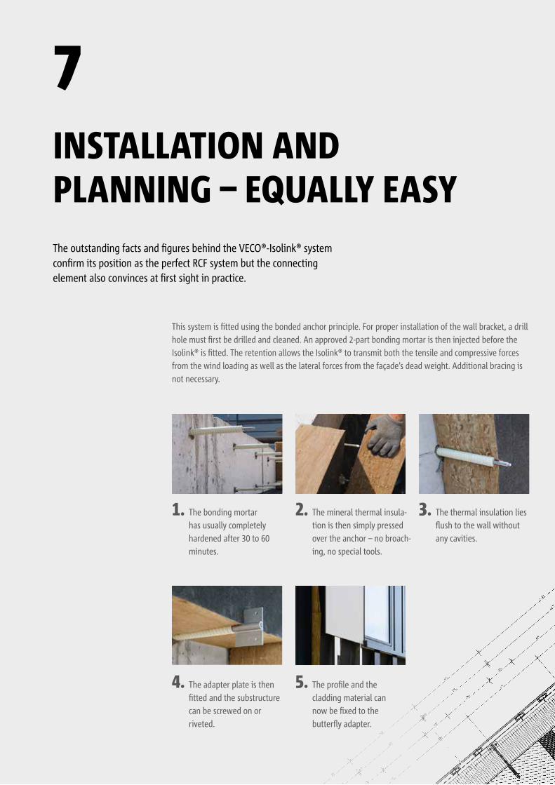
INSTALLATION AND PLANNING – EQUALLY EASY
7
4. The adapter plate is then fitted and the substructure can be screwed on or riveted.
5. The profile and the cladding material can now be fixed to the butterfly adapter.
1. The bonding mortar has usually completely hardened after 30 to 60 minutes.
2. The mineral thermal insula-tion is then simply pressed over the anchor – no broach-ing, no special tools.
3. The thermal insulation lies flush to the wall without any cavities.
The outstanding facts and figures behind the VECO®-Isolink® system confirm its position as the perfect RCF system but the connecting element also convinces at first sight in practice.
This system is fitted using the bonded anchor principle. For proper installation of the wall bracket, a drill hole must first be drilled and cleaned. An approved 2-part bonding mortar is then injected before the Isolink® is fitted. The retention allows the Isolink® to transmit both the tensile and compressive forces from the wind loading as well as the lateral forces from the façade’s dead weight. Additional bracing is not necessary.
OKFFB
5
+21.84
.600
.500
.150
.250
.876
+18.05
+17.85
OKFFB±0.00
.600
.900
.292
.008
.892
.210
.350
.300
.350
.130
.600
.254
.130
.200
.012
.700
.400
.700
.026
.023.01
2
.301
.495
.495
.210
.008
1.192
.292
.008
.008
.592
.308
1.200
.300
.008
2.500
.013
.036
UK ROHDECKE
OKFFB
5
+0.08
OKFFB+0.10
OKFFB+0.11
OKFFB+0.22
.160
.250
+6.65
UK ROHDECKE
+6.65
UK FERTIGDECKE
+6.39
UK ROHDECKE
+6.13
UK FERTIGDECKE
OKFFB
3
-0.26
OKFFB
3
-0.41
-0.35
UK ROHDECKE
-0.415
UK FERTIGDECKE
-0.943
UK ROHDECKE
-1.008
UK FERTIGDECKE
.065
FASSADENDETAIL-11 - VERTIKALSCHNITT B-B - M 1:10
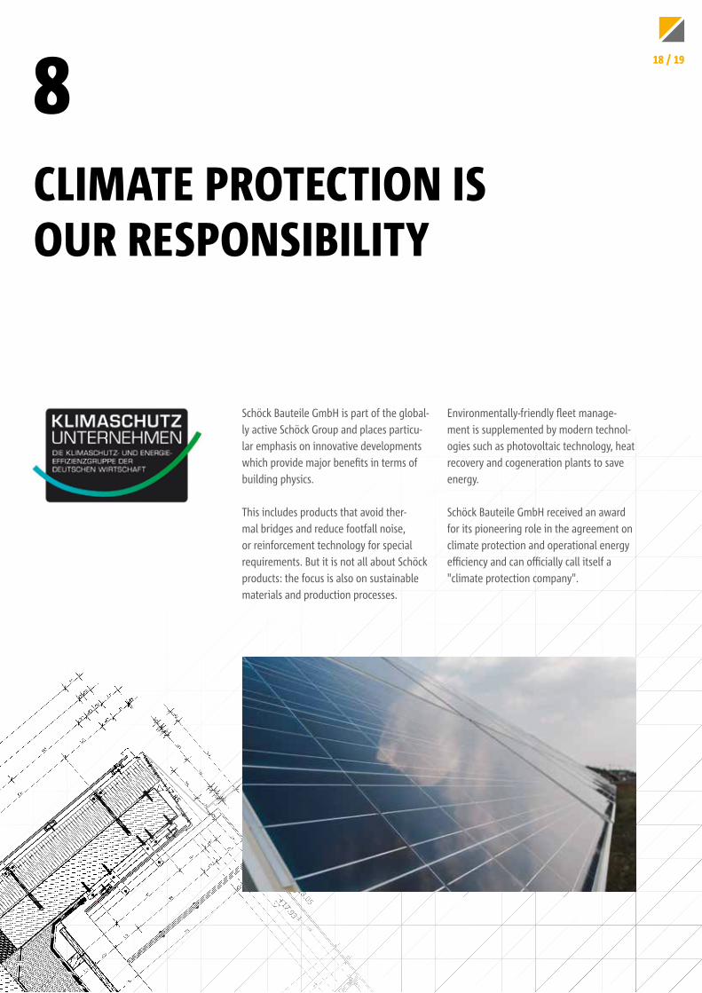
CLIMATE PROTECTION IS OUR RESPONSIBILITY
8
Schöck Bauteile GmbH is part of the global-ly active Schöck Group and places particu-lar emphasis on innovative developments which provide major benefits in terms of building physics.
This includes products that avoid ther-mal bridges and reduce footfall noise, or reinforcement technology for special requirements. But it is not all about Schöck products: the focus is also on sustainable materials and production processes.
Environmentally-friendly fleet manage-ment is supplemented by modern technol-ogies such as photovoltaic technology, heat recovery and cogeneration plants to save energy.
Schöck Bauteile GmbH received an award for its pioneering role in the agreement on climate protection and operational energy efficiency and can officially call itself a "climate protection company".
18 / 19
ON-SITE FAÇADE ADVICE SERVICE Our product engineers and project supervisors provide support for planning and the correct fitting of façade substructures.
STRUCTURAL AND THERMAL ANALYSIS Our engineers provide support during planning and verification.
DETAILING AND INSTALLATION PLANNING Our engineers can also take on the complete detailing and construction documentation if required.
DETAILED CAD DRAWINGS Design details for planning are available from our DetailCentre in all the usual CAD file formats. www.schoeck.de/de/detailcenter-de/isolink
FITTING VIDEO Every step of the fitting process can be followed in detail with our fitting video. www.schoeck.com/isolink-installation
GIP GmbH Friedrich-Seele-Straße 1b38122 BraunschweigGermanywww.gip-fassade.com
Schöck Bauteile GmbHVimbucher Strasse 276534 Baden-BadenGermanywww.schoeck.com
Façade Solutions²Tel.: +49 7223 967-144Fax: +49 7223 [email protected]
OUR SERVICE
9
804792/01.2021/INT/200586