energy saving project profile - arab...
TRANSCRIPT


Energy Saving Project Profile
Replacement o f Secondary Reformer wi th Modi fied Design Secondary Reformer Concern: During April 2005 turnaround, the Process Gas Cooler (PG Cooler) downstream the Secondary Reformer of Ammonia Plant was successfully replaced with a new PG Cooler. However, just after the two months of operation, the mid path temperature of the PG Cooler started increasing; indicating that fouling in the first compartment is continually increasing. The only source of fouling material was attributed to the Secondary Reformer refractory lining which was silica based refractory material. The Hydrogen rich process gas considerably leaches out Silica from refractory at higher temperatures in reducing atmospheres. Furthermore, the Secondary Reformer was running for more than 20 years and the recommendation was to prepare for a complete relining of refractory. Action Taken :
Opportunity was taken to enhance the efficiency of secondary reformer by introducing a modified secondary reformer with following improved design features : 1. Better mixing of gas and
air by creating a vortex flow (lower methane slip).
2. No metallic burner in the
combustion zone and thus no replacement of the burner ring required.
3. Sufficient residence time
to achieve a uniform temperature before the gas enters the catalyst bed.
4. Avoidance of flame
impingement on the refractory or catalyst.
5. The back-up insulation
layer for the new Secondary Reformer was to be of low silica type, unlike the existing type which is of high silica content.
6. The total estimated
period for replacement was around 24 days.
A detailed economic evaluation was done and concluded that installing a
new secondary reformer with modified design was techno-economically a better option. Actual Performance : After the installation in November 2007, the new Secondary Reformer was put in service in December, 2007. With the new burner arrangement, flame impingement on the catalyst could be avoided and thus preventing damage of the catalyst. The new design facilitated addition of more process air owing to the improved burner design and arrangement and larger space for better mixing of process gases and the process air. This has resulted in the reduction of methane slip from 0.25% to 0.18%. The new Secondary Reformer helped in increasing the Ammonia production by around 5% i.e. 60 MTPD and reduction in specific energy consumption by 3.7 % i.e. 0.34 Gcal/MT of ammonia.

Energy Saving Project Profile
Reformer Tubes Replacement in Ammonia Plant to take advantage of reduced specific energy consumption : Reasons for GPIC to replace Reformer tubes
The Methanol and Ammonia Plant Reformers are top fired Uhde design with a) 315 tubes arranged in 7 rows (45 tubes / row) in methanol ; b) 240 tubes arranged in 5 rows (48 tubes / row) in ammonia
The Methanol Reformer tubes had completed 97,000 hrs (for tubes replaced in 1996) and 81,000 hrs (for tubes replaced in 1998) from their design life time of 100,000 hrs. Despite some useful running hours remaining, the tubes were
replaced for the following reason:
To increase the Methanol plant capacity by changing the existing tubes material from 35/25 Ni/Cr to micro-alloy tubes as the catalyst volume in the new tubes increases due to reduced thickness of the tubes for the same OD. The advantages of the micro-alloy tubes are:
a. Increase in the tubes
inner diameter due to reduced thickness.
b. Better creep ruptures strength.
c. Lower heat flux. d. Lower tube wall
temperature. e. Improve reliability.
Actual Performance: After the installation in November 2007, the new Reformer Tubes were put in service in December, 2007. The new tubes helped in increasing the Methanol production by around 2.9% i.e. 33 Ton/day and energy saving of 0.4% i.e. 0.04 Gcal/MT of Methanol. Accordingly, a similar replacement is planned for ammonia reformer as well, to obtain specific energy advantage.
Energy Saving Project Profile
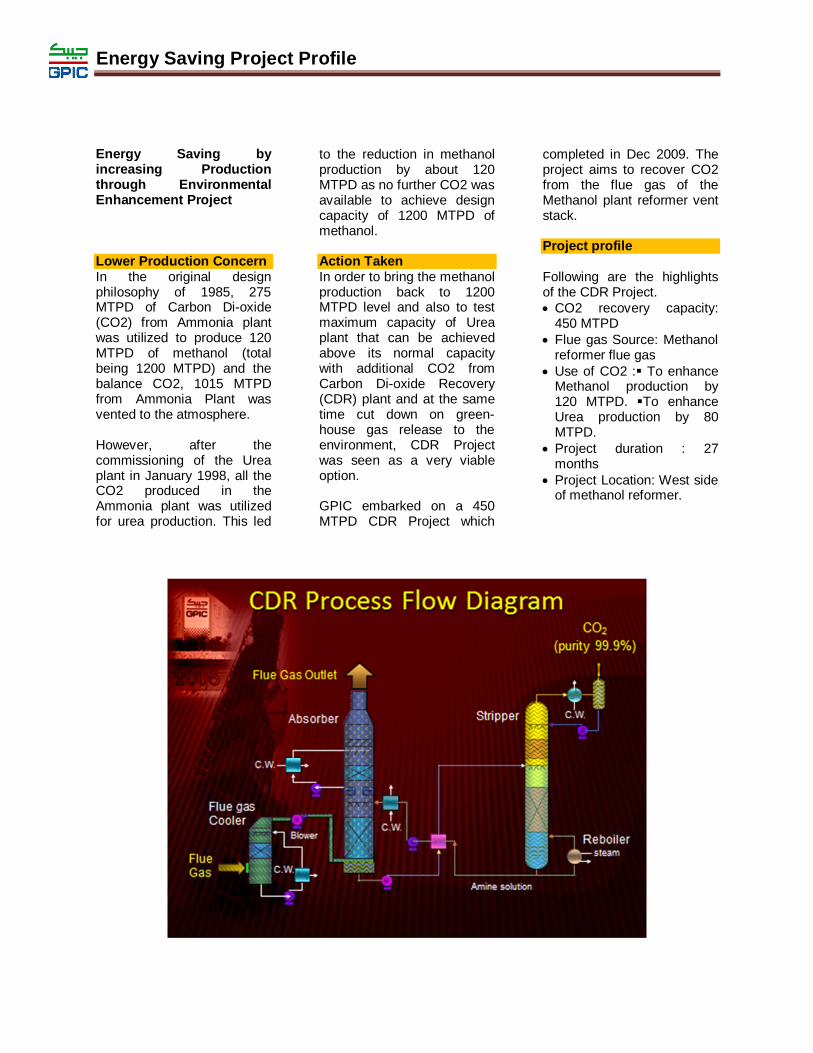
Energy Saving by increasing Production through Environmental Enhancement Project
Lower Production Concern In the original design philosophy of 1985, 275 MTPD of Carbon Di-oxide (CO2) from Ammonia plant was utilized to produce 120 MTPD of methanol (total being 1200 MTPD) and the balance CO2, 1015 MTPD from Ammonia Plant was vented to the atmosphere. However, after the commissioning of the Urea plant in January 1998, all the CO2 produced in the Ammonia plant was utilized for urea production. This led
to the reduction in methanol production by about 120 MTPD as no further CO2 was available to achieve design capacity of 1200 MTPD of methanol. Action Taken In order to bring the methanol production back to 1200 MTPD level and also to test maximum capacity of Urea plant that can be achieved above its normal capacity with additional CO2 from Carbon Di-oxide Recovery (CDR) plant and at the same time cut down on green- house gas release to the environment, CDR Project was seen as a very viable option.
GPIC embarked on a 450 MTPD CDR Project which
completed in Dec 2009. The project aims to recover CO2 from the flue gas of the Methanol plant reformer vent stack. Project profile Following are the highlights of the CDR Project. CO2 recovery capacity:
450 MTPD Flue gas Source: Methanol
reformer flue gas Use of CO2 : To enhance
Methanol production by 120 MTPD. To enhance Urea production by 80 MTPD.
Project duration : 27 months
Project Location: West side of methanol reformer.

Energy Saving Project Profile
Actual Performance Methanol production increased from 1080 to 1200 MTPD with a drop in the
specific energy consumption of Methanol. Urea Production increased by more than 80 tons per day
and the specific energy consumption also reduced.

Energy Saving Project Profile
Urea Stripper Replacement to take advantage of reduced specific energy consumption : Urea Stripper Urea stripper is considered to be somewhat specialized as urea manufacturing process poses many challenges due to the nature and the temperature – pressure conditions of the process streams. It is the single equipment which is prone to maximum corrosion as the insides of its tubes are generally considered to have the worst corrosion issues. The stripper construction involves exotic metallurgies to ensure that it is robust enough to withstand the extreme corrosive environment of the process. Over the years, Snamprogetti - the technology licensor introduced Titanium tube strippers and later Bimetallic tube (25Cr/ 22 Ni/ 2 Mo, and Zirconium) strippers. Bimetallic tubes were considered to be superior to the Titanium tubes for combating the corrosion / erosion problems encountered during the stripping process. GPIC, therefore selected a Bimetallic tube stripper which was the latest technology prevailing during the design stage of the Urea plant in 1996-97. Issues / concerns The Bimetallic tube of the stripper at GPIC had 2 mm thickness of 25:22:2 austenitiv steel and 0.7 mm thickness of Zirconium. Due to weldability issues, 20 mm of the inner Zirconium lining has been removed at the top
and bottom ends of the tubes. This stripper was in service for 10 years since 1998 and had been inspected several times during the turnarounds as it had been facing the corrosion problem of late. While evaluating the options for replacing the existing bimetallic stripper with a new one, Snamprogetti informed that it developed a robust, advanced tubing design for the strippers known as Omega Bond, where the Titanium and Zirconium metals are plastically forged together at a temperature well below their melting points to avoid the alloy formation and the possibility of disbonding of the two metals which has been a chronic problem in the bimetallic tubes design.
Action taken to overcome the concerns GPIC, after making a detailed study, decided to opt for Snamprogetti’s (SP) latest design of strippers using the Titanium and Zirconium bimetallic tubes that are manufactured with a special process of extrusion bonding and Inertia Welding. The new tubing solution utilises solid-state joining technology where the interface between the two metals never reaches a molten state. Hence, no alloy is formed in a joint that has virtually no diffusion zone, no inter-metallic compounds, and no alloying. Likewise, the heat affected zone is negligible. The new stripper was designed to match with the existing dimensions to avoid any modification to the
connecting piping and foundation etc. Actual Performance This new stripper offered following advantages: Corrosion-free operation
due to use of Titanium and Zirconium, hence longer life of operation expected up to 25 years.
Due to increased temperature of the bottom of stripper from 204 to 212 °C, it shall be possible to have the flexibility to increase the load of the plant by an estimated 10 to 15%
Increased energy efficiency due to lower solution recycled and increased steam generation in the HP loop.
Discontinuation of the use of high pressure passivation air, resulting into potential saving in operating and maintenance cost.
Increased plant reliability.

Energy Saving Project Profile
Replacement of Converter Basket in Ammonia Synthesis Converter – a step for minimizing energy consumption Reasons for GPIC to replace the existing basket: 1.The existing basket was installed in 1989. It was inspected in 1996. It will complete 23 years in 2012. Deterioration of the basket (nitriding effect, damage to the screens) is a possibility.
2.Present charge of ammonia converter catalyst will be in service for 16 years by 2012 and next replacement hence, needs to be replaced.
Hence, to enhance the reliability of the Ammonia Plant, it was recommended to replace the existing basket alongwith the catalyst.
Proposal for new Ammonia Converter Basket GPIC was recommended to change the basket design in a way that the new one could be installed in the same shell without any major modifications to the Converter shell. Salient features of the proposed basket are as under:
Two radial beds each loaded with pre-reduced catalyst of size 1-3 mm. The catalyst volumes are as under:
Top bed volume 7.0 m3
Bottom bed volume 14.1 m3
Total 21.1 m3
The material of construction of the basket shall be SS321.
Heat Exchangers
Heat exchanger area 129 m2
Lower heat exchanger 241 m2
Process performance of the proposed basket
The loop pressure is expected drop to ~276 + 5 barg from the present 310 barg.
Pressure drop across the converter shall be around 2.5 barg
Outlet temperature of the converter shall not exceed 383 DegC
The circulation flows shall remain almost similar.
The overall heat duty on the cooling water network and the refrigeration system shall remain almost similar.
No addition of equipment is envisaged
Reliability studies for the backend were carried out to ascertain whether all the equipment parameters will be well within the design limits.
Reliability study of the frontend of Ammonia Plant was also carried out to ensure the safety and reliability of the frontend at a load of 1340 MTPD
An energy audit of the Ammonia Plant also carried out and confirmed that the basket replacement will help in bringing down the specific energy consumption per tonne of ammonia.


Energy Saving Project Profile
1. Replacement of Process Gas (PG) Cooler E-0301 in Ammonia-3 plant.
Frequent Fouling of old PG Cooler (E0301) in Ammonia-3 plant Concern: Qatar Fertilizers Company, Ammonia-3 plant is designed and supplied by M/s UHDE. The plant is designed to produce 1500 MTPD of Ammonia and commissioned in January’1997. The process gas cooler (PG cooler) at the downstream of the secondary reformer is designed to cool secondary reformer effluent from 999 ºC to 627 ºC (EOR) by generating saturated high pressure steam. The PG cooler was facing the problem of fouling since 1998-99 after the plant got stabilized at higher load and a higher online factor was achieved. Due to fouling, the PG cooler outlet process gas temperature slowly increases from 550ºC (after cleaning the tubes during shutdown) to 690ºC (with fouling inside the tubes). Steaming was the regular practice for de-fouling of the PG cooler. Online steaming (by increasing the steam flow through process air coil) was the repeated phenomena for de-fouling of the tubes. The interval of steaming was 30-40 days i.e. once per month before year 2004. In the annual shutdown of 2004, the primary reformer catalyst, the secondary reformer catalyst and all the secondary reformer support materials (alumina lumps and alumina balls) were changed. After the 2004 shutdown, the severity of fouling in the PG
cooler increased and even steaming was not beneficial for de-fouling of the PG cooler. The interval of steaming was 7-10 days after initial steaming period i.e. 40 to 45 days after start-up. Samples of PG cooler fouling deposits (analyzed in January 2007) have shown all the available components of the upstream primary and secondary reformer refractory, the secondary reformer support materials and the primary & secondary reformer catalysts. The problem was analyzed by a complete in-house study of the upstream refractory and catalyst materials during June 2007. Samples of refractory materials, secondary reformer support materials and catalyst materials were analyzed. The problem was identified to be the support material of the secondary reformer i.e. alumina lumps installed at the top of the secondary reformer for the protection of the catalyst. The alumina lumps were removed from the top of the secondary reformer catalyst bed in the September 2007 unforeseen shutdown. The severe PG cooler fouling stopped after the removing of the alumina lumps from the top of the secondary reformer. Action Taken:
During Sept 2007 shutdown: The top alumina lumps (280 mm) were removed. The top protective catalyst bed of 330 mm was removed. A bigger size catalyst was loaded (figure 16) on the top of the main
Catalyst bed as a protective support material. As a result the distance between the catalyst bed and the burner tip increased by around 300 mm. The PG cooler tubes were hydro-jet cleaned to remove the deposits. The cleaned PG cooler was in operation for almost 2 years (from Sept 2007 till Mar 2009) with outlet temperature stabilized to 640oC after 100 days of operation. A detailed economic evaluation was done and concluded to install a new PG Cooler & Steam drum at its accessories of higher capacity considering 130% Ammonia-3 plant load conditions. Actual Performance: The new PG cooler and steam drum was installed during Qafco-3 major shutdown in 2009 with installed capacity to handle the Ammonia -3 plant load upto 130 %. The following benefits achieved after installation of new PG Cooler:
1. The exit temperature of PG cooler is operated well within range of 590-610oC.
2. No further fouling in PG Cooler observed.
3. Better heat exchange capacity.

Energy Saving Project Profile
2. Installation of CO2 Booster in Qafco-3 (Ammonia & Urea -3) plants
Concern:
The Ammonia-3 plant generates by product CO2 at a pressure of 18 kPa and designed to supply CO2 to Urea-3 plant at a pressure of around 12 kPa. During summer, CO2 compressor turbine speed limiting the Urea production due to low CO2 suction pressure and has negative impact on Urea-3 plant production.
To reduce the up-time in summer period, CO2 booster blower was installed in May'2009.
So, to overcome CO2
compressor capacity limitation, installation of CO2 booster was proposed at suction of CO2 compressor in Urea-3 plant.
Action Taken:
The new CO2 booster was
installed in May 2009. The CO2 pressure is boosted from 15 Kpa to 45 Kpa, thereby avoiding limitation on CO2 compressor and uptime production loss of Urea plant
Actual Performance: The following benefits were
achieved after installation of CO2 booster are
1. The savings in overall steam
consumption by 2 MT/hr. 2. Due to reduction in CO2 slip,
the Ammonia-3 plant production increase by 3.5 MTPD
3. Urea -3 plant uptime production loss reduced substantially to 13,833 MT per year.
4. Overall improvement in CO2 export by 5 MT/hr.
Energy Saving Project Profile
3. Instal lat ion o f Co-Generat ion - 1 un i t in Qafco Replacing Old Power PS 1.7 station & old vintage auxiliary boilers in Ammonia 1 & 2 plants Concern:
The present old auxiliary boiler in Ammonia-1 & 2 belongs to old generation boilers (2 nos) producing saturated steam at 12 and 26 bar respectively. These boilers do not equipped with proper heat recovery system i.e absence of air pre-heater & economizers etc, thereby the thermal efficiencies of these boilers are low.
The old Power
station (PS 1.7) also belongs to conventional electric power system based on once through cycle. The electric generation capacity is about 25-30 MWh with an overall efficiency of 20-22%.
Action Taken: Co- Generation also known as Combined heat and power (CHP), is an efficient, clean, and reliable approach to generating power and thermal energy from a single fuel source. By installing a CHP system designed to meet the thermal and electrical base loads of a facility, CHP can greatly increase the facility's operational efficiency and decrease energy costs. At the same time, CHP reduces the emission of greenhouse gases, which contribute to global climate change.
These old vintage auxiliary boilers and power station (PS 1.7) shall be replaced after new Co-Generation unit. The electric
power generating capacity of 64 MWh and 300 MT/hr of superheated steam at MP pressure of 50 bar. Actual Performance: The new Co-generation unit has been installed & is under commissioning phase. The actual performance of the Co-generation unit is expected as per design intent.
Energy Saving Project Profile
4. Replacement o f h igh Pressure Carbamate condenser wi th Pool condenser in Urea-2 p lant High Pressure Carbamate Condenser Concern:
The Urea-2 plant is based on Stamicarbon technology and commissioned in 1978. The High Pressure Carbamate condenser (HPCC) of Urea-2 plant was manufactured by Kobe Steel Ltd, Japan and installed in 1978. The need to replace HPCC was felt after frequent tube leakage incident of the HPCC occurred after July2004. The plant had to be stopped 6 times during 1993 to 2006 including 4 stoppages with in a period of two and a half year (July 2004 to Dec 2006).
Action Taken:
There had a choice between like by like replacement of HPCC and to replace the HPCC with Pool condenser. As Urea reactor of Urea-2 plant was replaced in 2004 with safurex lining and high efficiency trays, it was decided to replace HPCC with pool condenser with safurex lining. It was also decided to replace the high Pressure scrubber with newer deign. Both the equipment sized to get a designed capacity of 1900 MTPD Urea production keeping future revamp in mind. The both the equipment were replaced during 2007 turn around.
Actual Performance:
The replacement of HPCC was carried out due to performance of old equipment. However, the opportunity has been utilized to incorporate development in technology and equipments were sized to suit the future revamp. The replacement has not only increased the tolerance to plant upset but the HP Section performance has also increased. The conversion in the reactor has increased earlier and stripper efficiency has also increased earlier. The increase in HP section performance made it possible to stop one High Pressure Carbamate pump as both the pumps were running prior to replacement. The plant load has also increased by around 50 MT/day. The stoppage of one High Pressure Carbamate pump has resulted in Electrical energy saving of 0.01 GJ/MT of Urea. The overall saving in Electrical energy due to 2007 revamp has been calculated as 0.015 GJ/MT of Urea.


Energy Saving Project Profile
5. Increase in Suct ion Pressure o f CO 2 Compressor o f Urea-2 CO2 Compressor capacity Concern:
Urea-2 plant HP Section modification was carried out in year 2007. This has increased the capacity of HP Section to around 1600 MTPD. Low Pressure section has capacity to take this load with out any modification. In this new scenario CO2 compressor emerge as major bottleneck to increase the plant load even more CO2 is available. Major changes in CO2 Compressor section could not be taken up due to uncertainty in CO2 supply after QAFCO-6 commissioning. With replacement of The HP Stripper in 2011 turnaround, HP Section capacity has increased to 1900 MT.
Action Taken:
The option of increase of suction pressure was studied to get more flow through same compressor. CO2 is available at 48 kPa at the outlet of overhead cooler separator of Ammonia-2 plant in normal conditions. The pressure at the suction of CO2 compressor of Urea-2 used to be around 34 kPa before modification. The CO2
compressor suction pressure control valve and suction flow meter were found as cause of high pressure drop. The 16” suction pressure control valve was there in 24” line and causing a pressure drop
of 4kPa while orifice type flow meter was adding 3kPa in pressure drop. The valve has been replaced with 24” size valve and orifice has been replaced with Pitot tube type flow meter during 2011 turnaround.
Actual Performance:
The CO2 compressor suction pressure has increased to 39 kPa resulting in the 40-50 MT/day increase in Urea production. The increase in production with almost same fuel flow for Gas turbine has resulted in energy saving of around 0.1 GJ/MT of Urea production.


1
Recent Efforts in Energy Conservation in
Alexfert’s Ammonia Plant.
Fertilizer production consumes approximately 1.2 % of the world’s total energy on an
annual basis of which ammonia production accounts for 87 % of the industry’s total
energy consumption. Continual improvements are ongoing for improving the energy
efficiency of ammonia plants by implementing various energy saving schemes and
adopting efficient technologies for the new plants. This paper summarizes two case
studies implemented in Alexfert’s ammonia plant along with some different ways for
energy conservation in ammonia plants.
Author(s):
Eng. Khaled El-Sayed Mohamed
Eng. Mohamed Hassan Mowena
Alexandria Fertilizers Company, Alexandria, Egypt
Introduction
Continual engineering
efforts are ongoing to study
the energy conservation
possibilities for the
ammonia plants. Most of
these efforts aims in
reducing the gap in energy
consumption for the old
established plants with the
modern ones. Energy
efficiency in the
manufacture of nitrogen-
based fertilizers has
significantly improved. The
average net specific
consumption for modern
plants approaches 6.69-
6.93 Gcal/mt, while still
some plants are working on
the level of 7.88-13.9
Gcal/mt, and this suggests
that revamping less
efficient existing plants
would increase energy
efficiency, and reduce
production costs.
Energy Conservation
Efforts in Alexfert’s
Ammonia plant: Alexandria Fertilizers
Company (Alexfert) was
established as a joint stock
company in Oct. 2003 on
the coast of Abu Qir bay,
on the Mediterranean coast
of Egypt. The company
consists of an ammonia
plant with a capacity of
1200 MTPD, and urea
granulation plant with a
capacity of 2000 MTPD, in

2
addition to the necessary
Offsites and utilities.
The plants were
commissioned in Aug.
2006 with the main
contractor for the whole
complex is UHDE
Company. One of the
objects of the company
quality and
environmental policy is
to continually improve
the process execution and
resources management
including the energy
conservation.
Since the plant
establishment was based
on the latest proven
technology, the average
net specific consumption
for the plant was
designed as 7.288
Gcal/mt, while continual
efforts aims in optimizing
such figure as much as
possible.
Recently, two cases
were improved the
performance in two
different locations within
the ammonia plant which
shall be illustrated as
follows:
Case One: The
use of highly
effective ACT-1
activator, which
shows
substantial
benefits over
DEA in CO2
removal unit.
The CO2 removal
unit incorporates the use
of traditional benfield
solution based on
30 % potassium
carbonate (K2CO3) in
addition to an activator
(DEA) and corrosion
inhibitor (Vanadium
pentaoxide). The
activator concentration is
3 %, which is added to
the carbonate solution for
improving the absorption
rate of CO2. For many
years, DEA
(diethanolamine) has
been the standard
activator and is still used
in many operating plants.
However, the unit
suffers from the
following problems:
i. Thermal
degradation of
DEA.
ii. Chemical
degradation of
DEA due to
reaction with
reoxidizing
agents used to
oxidize the
corrosion
inhibitor
(vanadium)
from V+4 to
V+5, along with
the formation
of non
regenerable
large molecular
weight
polymeric
chemicals and
heat stable
salts. This
results in
system
foaming and
increasing the
corrosion
products along
with H2

3
slippage from
desorber which
limiting the
operation of
urea plant.
Recently, ACT-1
(an alternative product
developed by UOP Co.)
proves as a more-stable
molecule that is more
resistant to degradation.
The features of the
benfield unit designed for
activation with ACT-1
instead of DEA could be
summarized as follows:
i. Potential for
capacity increases
of up to 10 % in the
CO2 removal unit.
ii. Potential reduction
in regeneration heat
by up to 10 %.
iii. Potential reduced
solution pumping
requirements by up
to 10 %.
The above
mentioned benefits along
with overcoming the
problems in the unit’s
operating parameters
were considered, and
decision was taken to
change the benfield
solution activator to be
ACT-1 instead of DEA,
the job was held during
turnaround performed for
year 2011. The results
could be illustrated as
follows:
1. Increase in the
absorption capacity
by 20 % decrease in
the CO2 slippage.
2. Reduction in
regeneration heat
for the benfield
solution by 20 %, in
other hand the
specific
consumption is
reduced by almost
0.025 Gcal/ mt
ammonia.
3. Reduction in
pumping rates by 5
% due to significant
decrease in the
absorption solution
circulation flow
rates.
Case Two:
Replacement of
W.H.B. in Ammonia
Synthesis unit.
The waste heat
boiler installed
downstream of the
ammonia converter is an
Uhde designed Fountain
type vertical WHB. It
consists of 400 freely
movable U-tubes, and is
located downstream the
ammonia converter to
cool down the gases
outlet the Converter from
456 °C to 306 °C against
boiler feed water. The
boiler feed water is
preheated to be close to
the boiling point in
especially pre-heating
part and saturated steam
with 329 °C is generated
in the evaporating part.
The converted gases are
introduced in the tube
side at a design pressure
of 184.8 bar abs, and the
steam is generated in the
shell side at 127 bar abs.
One year after the
initial start-up, the boiler
4
suffers from two repeated
failures, of which the
synthesis section
operating conditions were
optimized.
The in house
comprehensive studying
for the similar cases
along with the continual
successful
communications with the
designer (UHDE)
revealed the need to
modify some of the
equipment design
parameters along with
increasing the boiler
capacity by 10 % for the
ease of maximizing the
HP-steam production
with maintaining safe and
stable operation.
The new equipment
was successfully installed
during turnaround held in
October 2009, with the
following performance
main features:
i. The synthesis
section is running
over its name plate
capacity (almost
103 %).
ii. Steam production
increased by 10 %
over the old one,
which is
equivalent to
almost 0.05
Gcal/ton
ammonia.
iii. The new boiler
outlet temperature
decreased from
306 to 289 °C.
Energy Conservation
results due to
application of the two
cases, results in
reducing energy per to
ammonia to 0.075
Gcal/mt ammonia,
which equivalent to
500,000 $/year.
Developments and
opportunities:
Developments in
the ammonia production
technologies runs
simultaneously with the
idea of revamping or
modifying the existing
plants for the ease of
increasing their
efficiencies, maximizing
economics or elimination
bottlenecks in order to
match with modern
technologies and reduce
energy consumption to
remain competitive.
Continuous developments
in process technology,
catalyst and design and
material of construction for
equipments offered
opportunities to all existing
plants to improve energy
efficiency, while selecting
the proper development is
governed by each plant
own case, technology used,
and the management
review of the resources
with the evaluation of the
process capital and
operating investment costs.
Of the possible points to be
considered, we can
illustrate the following
points of which should be
studied carefully prior to
selecting the applicable one
or more as follows:
Reforming
Section: the main
object is to
reduce the steam

5
to carbon ratio,
which could be
through various
ways as follows: i. Establishment
of modern
reformer tubes
with better
metallurgy,
higher strength,
and thinner
wall that allow
higher heat
transfer, larger
inner space for
catalyst
packing, and
saving energy.
ii. Energy
conservation
through the
utilization of
excess heat in
flue gases
liberated from
reformer box
through new
coil in
preheating of
other streams
depending on
stack
temperature.
iii. Installing pre-
reformer which
reduces significantly
the firing duty in the
primary reformer to
be installed in a new
convection coil or as
a separate heater.
iv. For secondary
reformer, short
catalyst loading
improving the
combustion zone and
the reforming zone,
respectively.
CO Shift
converters: the
utilization of
better designed
exit nozzles for
the two reactors
markedly
improves the
vessels pressure
drop which in
turn aids in
synthesis gas
turbine power
saving.
CO2 removal:
Changing the
packing in
absorption and
desorption
columns for
better mass
transfer
efficiency along
with the proper
selection for the
absorption
activator for
reducing energy
paid per CO2
extracted. One of
the attractive
points is the
replacement of
the single stage
flash drum with
multi-stage one
aiming in
decreasing the
steam
requirements.
Methanator and
synthesis gas
suction: i. Drying of the
synthesis gas
allows the gas to be
fed directly to the
inlet of the
converter rather
than being fed into
the loop before
ammonia separator.
ii. Chilling of
make-up
synthesis gas
helps in saving

6
the synthesis
compressor
power by 9 %
per 30 °C, to be
utilized for
increasing plant
rate or
decreasing
power
consumption
for synthesis
gas turbine.
Ammonia
Synthesis:
Modifying the
ammonia
converter basket,
aiming in
enhancing the
flow direction
from axial to
radial or axial-
radial, thus led to
the possibility of
using more active
catalyst of finer
particle size
without
increasing the
pressure drop
through the
reactor led to
potential saving
of 0.2-0.3
Gcal/mt. The
proper design for
waste heat
recovery from
synthesis gases
exit converter
also aims in
recovering the
excess heat and
improving the
heat duty for
ammonia
refrigeration
cycle.
Purge gas
recovery: aims
in the selective
recovery of
ammonia and
hydrogen from
the purge gas
where the
hydrogen is
recycled to the
synthesis loop
and ammonia
increases the
plant
productivity, the
idea reduces the
specific energy
consumption
from 0.15-0.25
Gcal/mt.
Catalyst used:
the selection of
the catalyst to be
used in the
overall process
stages is of great
importance, since
selecting higher
activity catalyst,
with the lowest
possible pressure
drop and high
conversion rates
significantly
improves the
productivity and
energy needs.
Steam system:
the effective
control of leaked
points from
steam system
vents
significantly
improves the
process
efficiency. This
could be
managed by
applicating the

7
modern control
systems.
Conclusions
The energy
conservation philosophy
became an essential for
making the ammonia
manufacturing competitive,
taking into account the
following points:
i. The great
opportunity for
revamping the old
plants which has a
great marginal
limits, in comparison
with the new plants,
to improve their
performance by
selecting one or
more of the energy
conservation
techniques.
ii. The continual
increase in the prices
of the energy
resources pulls the
manufacturers to
enable and promote
further technological
advancements that
will reduce energy
consumption.
References
1. F. Kessler, D.
Hoberg and S.
Hruby, First
Application of
Uhde’s dual pressure
ammonia process for
revamping of the
Duslo Ammonia
plant, Nitrogen
Conference and
Exhibition , Austria
(2006).
2. Retrofits for ageing
ammonia plants,
Johnson Matthey
Catalyst Seminar,
Egypt (2008)
3. S.K. Furukawa and
R.K. Bartoo,
Improved Benfield
Process for
Ammonia Plants,
UOP, USA, (1997).
4. J. J. de Wit, A.
Riezebos, Upgrading
a 25 year old
Ammonia plant
resulting in Lower
Energy Consumption
and Higher
Production Capacity,
AIChE (1998).
5. S. NAND and M.
Goswami, Recent
Effort in Energy
Conservation in
Ammonia and Urea
plants, Indian J.
Fert., Vol. 4 (12), pp.
17-20 (2008).


PROJECTSFORENERGYSAVINGANDOPERATIONALFLEXIBILITY.
Page 1 of 5
MODIFICATION PROJECTS TO REDUCE ENERGY CONSUMPTION IN AMMONIA AND UREA PLANTS OF OMIFCO, OMAN
AMMONIA PLANT:
Relocation of P-323-C Pump discharge in GV CO2 removal section: In Ammonia plant two reciprocating plunger type pumps P-323-A/B were provided for CO2 compressor condensate recovery and purification. These pumps Capacities (3.0 M3/hr each) were on lower side and were not meeting the plant generated condensate capacity requirement. Subsequently one additional new centrifugal pump P-323-C of higher capacity (10.0 M3/hr) was installed. This pump develops a discharge pressure of 4.0 bar g and was earlier discharging condensate to V-307 vessel which operates at 0.2 Bar G pressure. From V-307 condensate is pumped by P-308 to different high pressure and
low pressure condensate consumers. P-308 pump develops a discharge pressure of 38.0 Bar gauge.
From P-308 pump discharge 12 to 15 MT/hr of high pressure condensate was being sent to the suction of Lean solution pump P-302-A/B (operates at 1.5 Bar.G) for maintaining GV system water balance through a pressure let down valve FV-3101.
Action Taken:
It was observed that by connecting P-323-C pump discharge header at downstream of FV-3101 about 5 to 9 MT/hr high pressure condensate drawl from P-308 could be reduced and P-323-C pump would directly send water to P-302 pump suction.
Further it was acknowledged that this modification would help in avoiding double pumping of condensate in P-323-C & P-308 pumps before sending condensate to the suction of P-302 pump. And after this piping modification P-308 pump’s operating power consumption will reduce by 27 KW.
Subsequently this modification was implemented and annual power savings of about 0.225 Million KWHS per Ammonia plant is being achieved.
The payback period for the scheme was less than six months. This modification is implemented in both the Ammonia plants. (Refer Drawing at Annex-1)
P-308 A/B V-307
P-302 A/B GV Lean SolutionPumps
3"-22-PC-3005-31A-V
FV-3101
3"-22-PC-3003-35C-V
Excess Condensate to V-321
2"-21-P165-33C-V
3"-22-PC-3062-31A-v
Modified Existing 2" line
2"-21-P165-33C-V
New Proposed 3" line connection
3"-22-PC-3001-35C-V
ANNEXURE-1
Exisiting Lines
Modified Existing Line
Proposed Line
New location of NRV
P-323-A/B and C
Newcontrol valve
SCHEMATIC DRAWING FOR P-323-C NEW PUMP HOOK UP
1" or 3/4" drain

PROJECTSFORENERGYSAVINGANDOPERATIONALFLEXIBILITY.
Page 2 of 5
UREA PLANT:
1.0 Relocation of Passivation Air injection point from CO2 compressor first stage suction to the second stage suction.
Urea manufacturing process involves addition of passivation air for protecting the alloy steel surfaces of high pressure equipment from corrosion. As per the original design passivation air (750 Nm3/hr)
had been introduced at the first stage of the CO2 compressor (Operates @ 0.75 Bar G) and now it is injected at the second stage suction (Operates @ 5.85 Bar G) of CO2 compressor.
Action Taken:
This modification could be envisaged & implemented because the source of passivation air used for injection was from a source of 14.0 Bar G coming from third
stage discharge of Ammonia plant process Air compressor. This modification involved use of 2” pipe of about 50 Meters length and fittings. The power saved in CO2 compressor is about 45 KW per hour per plant. Annual savings is about 750 MWHRS in the complex. Payback period is less than three months. (Refer Drawing at Annex-2)
Process Air CompressorK-421 of Ammonia Plant
3rd Stage Discharge
Back up Airto Offsites
Passivation Air supply to/ fromother Ammonia Plant
2" Line
CO2 Compressor
First StageSecond Stage
0.7 BarG &45 Deg.C
5.83 BarG &44 Deg.C
2" New proposed line
SCHEME FOR POWER SAVINGS IN CO2 COMPRESSOR
13.74 BarG &41 Deg.C
13.74 BarG &41 Deg.C
2" Line
E-119
V-120V-121
E-120
V-119
FV-1001
4" Line
Exisitng 1" Drain
CO2 fromAmmonia Plant
ANNEXURE-2
1" Drain
2.0 Ammonia recovery from LP section Vent of Urea-11 unit:
In both the Urea plants at higher loads significant
Ammonia losses were experienced, from the LP section vent gases. This Ammonia quantity was in the range of 500 to 1200 KGS/hr. Several plant optimization
efforts were tried to reduce these losses but could not be reduced much. Compared to other similar plants, Urea plants at OMIFCO do not have water scrubber/cooler arrangement

PROJECTSFORENERGYSAVINGANDOPERATIONALFLEXIBILITY.
Page 3 of 5
for vent gases Ammonia recovery.
Later on different technical modifications were studied for recovering this Ammonia. Finally a scheme was developed by using the spare unused E-113 carbamate preheater as a chiller for recovering these Ammonia losses. (Refer Drawing at Annex-3)
The vent gases containing Ammonia are sent to the E-113 tube side where 97% of the
Ammonia was condensed and the balance inert gases are sent to the flare. Ammonia is used as refrigerant on the shell side of the E-113 exchanger.
Action Taken:
After implementing the scheme in Urea-11 unit the recovered Ammonia quantity was measured and was found to be 28.18 MTPD.
The annual monetary gains shall be 0.96 Million USD per one Urea plant. The payback
period of the scheme is less than three months.
This scheme was implemented and commissioned in Urea-11 unit on July 6th 2011 and since then it had been running normal.
This scheme is under implementation in Urea-21 unit and similar benefits are expected. It is expected to be completed by end of October-2012.
To Discontinuous Flare Stack F-113
C-104 exit gases
1" LTCS Pipe
4" LTCS Pipe
Liquid Ammonia to be connectedto V-105 Ammonia Receiver at
the available 2" Nozzle Avaiable
2" LTCS Pipe
PV-1033A
PV-1033 B
Ammonia tapping from P-101-BSuc.I/V D/S 1" Drain
Liquid Ammonia @ 20.0 Deg.C
Vapor Ammonia to be connected to 6" Ammonia vapors retrun headerfrom AST to V-503 at D/S of Ammonia plant East side B/L valve
ExisitngE-113 Exchanger
PSE-1017A PSE-10178To V-111
P & I DIAGRAM FOR AMMONIA RECOVERY FROM C-104 OFF GASES
Existing Lines & Equipment.New Piping & Equipment
New tappingtaken during S/D
New tappingtaken in S/D
New Instrumentation
Demister Pad
New Reciprocating Pump for 2.0M3/hr Capacity @ 23.5 Bar Abs
discharge pressure.
LTX
This Bypass valvekept closed
3" LTCS Pipe
LCV
LCV
2" LTCS Pipe
6"-1
2-A
G-5
063-
53A
-F
East side B/L1st Isolation Valve
Exisitng 1"Tapping
PI
PIC
PSV
3/4" car Seal bypass
ANNEXURE-3
FROM C-104P48
6"-11-P94-31C-V 8"-11-BD21-31A-V
3" LTCS Pipe
3"-1
1-P9
4A-5
3A-F
1"-11-P67A-53A-V
4"-11-P67B-53A-VLAL
LAH
LALLAH 2"-1
1-P9
4C-5
3A-F
D43V113
P46 TO V-105
3"-11-P94B-53A-F
2"-1
1-P9
4D-5
3A-F
2"-11-P94D-53A-F
3/4"Drain
From Utility N2Header1"
AMMONIA-12 P17
P46 FROM S-102A/B

PROJECTSFORENERGYSAVINGANDOPERATIONALFLEXIBILITY.
Page 4 of 5
MODIFCATION PROJECTS FOR INCREASING THE OPERATIONAL FLEXIBILITY
UREA PLANT:
A. Conversion of Existing Process Condensate Storage Tanks to Urea Solution Storage Tanks.
In Urea Plants the Granulation Units require wet washing in every 25 to 30 days to maintain the Product Quality and operability. Whenever washing of Granulation units was carried out the Urea melt unit need to be reduced due to limited melt solution storing capacity.
Based on the available OMIFCO operated experience it has been noticed that the common off-spec condensate storage tanks of Urea Plants and Ammonia Plants could be converted into Urea melt storage tanks as Urea plants have their separate dedicated process condensate tanks for storing the process condensate. Both the tanks material of construction and design parameters have been evaluated and found to be suitable for storing the Urea melt solution.
Action Taken:
Subsequently Process Condensate tanks 11-T-125 of Urea plants and 22-T-321 of Ammonia plants were converted to suitable Urea melt storage tanks after making necessary compatible changes. One additional pump is also provided to transport back Urea solution from 22-T-321. 11-T-125 is inter connected with 11-T-101 in Urea 11 unit. After making these provisions now Urea plants melt units are operated at normal operated loads even if there is Granulator washing activity in either of the Urea Granulation units and Urea plant loads are not reduced.
B. Installation of additional PSV
on LP steam header in Urea Plants. In Urea plants the LP steam (3.4
Bar.G) network is interconnected as per the original design philosophy. It has been observed that by installing one additional PSV suitably on the LP steam header the Granulation
units can be operated in any combination of the Urea melt unit operation. That is if Urea-11 unit melt is under operation Urea-21 unit Granulation can be operated and visa verse is also possible. This additional PSV is warranted if there is any major maintenance activity on the HP carbamate preheater.
Action Taken:
Based on the assessed advantages one new PSV had been installed on Urea plants LP steam header and same has been found to be useful for crisscross operation of the Granulation units.
C. Installation of additional High capacity Screens in Granulation Units. In Urea plants as per the original
design four product screens were provided in each Granulation plant. These screens were giving frequent maintenance problems and the average on-stream factor achieved was on lower side. In view of the frequent recurring maintenance problems it was decided to install
one Rotex USA, make screen of higher capacity in each Granulation unit. This new screen could be accommodated in the occupied space of any one of the old screen and has thrice the capacity of the old screen. Action Taken: Based on the poor performance of the old Screens, two new Rotex screens of higher capacity having higher mechanically reliability were
installed one each in both the Urea plants. After installation of these new high capacity Rotex screens, in each Granulation unit the operational flexibility has increased and the Granulation units could be operated with increased on stream factor. Now any maintenance problems of the old screens could be easily sorted out and all the time there are two spare screens available for any unexpected breakdown of the running screens.

PROJECTSFORENERGYSAVINGANDOPERATIONALFLEXIBILITY.
Page 5 of 5
MODIFICATION PROJECTS UNDER IMPLEMENTATION:
AMMONIA PLANTS:
LP Flash Steam recovery from HP steam condensate:
OMIFCO is having a common Hydrogen Recovery Unit (HRU) for processing the synthesis loop purge gas of both the Ammonia plants. In the HRU the Ammonia distillation column has been provided with a solution Re-boiler which uses HP steam as the
heating medium. The HP steam used in the Re-boiler gets condensed and is transferred to the steam condensate network through condensate traps. It was observed that due to two phase flow conditions prevailing at the downstream of the condensate traps the downstream piping had been subjected to hammering and erosion damage at the elbow joints. Also the pipe line leaked on some occasions.
Action Taken:
In order to overcome these problems and to recover some flash steam a Flash vessel shall be installed at the downstream of the steam condensate traps in HRU. The recovered flash stem from the flash vessel shall be sent to the LP steam header and the condensate to the steam condensate network. Necessary tapings for the scheme have been taken and balance material is being procured for implementation. (Refer Drawing at Annex-4)
Annexure-4
New Steam CondnesateFlash Vessel
SCHEME FOR SEPARATION AND RECOVERY OF FLASH STEAMAND AVOID HAMMERING IN THE CONDENSATE HEADER.
Instrument Lines
Proposed modified Lines
Existing Lines
PSVS.P:6.0 Bar G
4"
LIC
HS Steam to the Reboiler25-E-553
Condensate Traps
Steam Condensateto 25-V-325
2"-25-HC6000-15B-V(PP)
To be connected to theLP steam header.
Filter
2"
2" 2"
4"-25-H
C6000-15B
-V(PP)
2"4"
3" Pipe
2" 4"
SUMMARY:
OMIFCO has been endeavored to improve the overall performance in terms of productivity, safety and operational flexibility by way of continuous introspection of their experience gained through operation since its inception and commissioning in the year 2005. This has paved way for the successful implementation of smaller modifications through established industry practices. *****

Arab Potash Co
APC

Energy Saving Project Profile
Recovery of Waste Heavy Fuel Fuel Filters Failure: APC Power Plant was constructed since the construction of the potash Plant in 1980. The Power Plant provides steam for the process and generates electricity with a capacity of 15 MW. Also, it provides many supplies to the Plant, one of which is the heavy fuel oil for running the product dryers. To ensure the purity of the heavy fuel oil to the boilers in the Power Plant and for the dryers in the Plant, there are two fuel filters installed upstream of the fuel transfer pumps. Each of the two fuel filters is in service for one shift (8 hours) while the other one is kept standby. At the beginning of each shift, the
operator switches the operation of the two filters so that the standby one becomes in service and vice versa. It had been an old measure since 1980 that after switching between the two fuel filters, heavy fuel oil is drained from the one which was in service to have it cleaned. And, that pure heavy fuel is sold as waste heavy fuel. This so-called waste heavy fuel was collected in an underground pit with a volume of 10 m³. This waste fuel always contains water which is directed to this same pit collected from the cleaning processes. Therefore, it was not easy to sell it for contractors since it contains water.
Action Taken: A modification was applied to retrieve this “waste” fuel. New piping and a new pump were installed. The fuel drained from the fuel filters is directed to this pit then pumped to the main storage tanks. As water is heavier than fuel, the operator, as a routine task, drains this pure water outside the tank as it settles in the bottom of the storage tank. Actual Performance: This modification has been in service for 3 years without selling any waste fuel, and hence saving an amount of 15 ton of heavy fuel per year. Also, avoiding the problem of getting rid of this “waste’' fuel.
Energy Saving Project Profile
Increasing the Reliability of the Power Plant:
Reasons of Economizer High Corrosion APC Power Plant has three steam boilers fired with heavy fuel oil. One of the boilers, whose steam parameters are 110 t/h, 63 bar (g), and 487 oC, was replaced in 2003 with a new one. It has an economizer to utilize the heat content in the flue gas. The manufacturer committed a design mistake which is not supplying the economizer with the required temperature of feed water (FW). He supplied it with the available FW whose temperature is 126 oC and a pressure of 2.4 bar (a).
The heavy fuel oil used for this boiler contains about 4.3 % sulfur by weight which means the FW temperature should not be less than 155 oC to avoid the corrosion of tubes due to the sulfuric acid condensation.
As the FW temperature and hence the tube wall temperature in the inlet portions of the economizer were below the sulfuric acid dew point temperature, 155 oC, sulfuric acid was condensing on the economizer tubes. And, the cold end of the economizer was facing severe acid corrosion and tube failures after few weeks (or even days) of repair. Action Taken There were only two options to solve this problem: the first of which is to accept sulfuric acid condensation and select an anticorrosion material for the economizer piping. The second option is to avoid sulfuric acid condensation through operating the economizer with a FW temperature above the sulfuric acid dew point temperature . These two options were studied taking into consideration the cost of materials, the complexity of implementation and the repair works needed in case
of failures, and the expected lifetime . Finally, APC adopted the solution of avoiding sulfuric acid condensation through operating the economizer with a FW temperature above the sulfuric acid dew point temperature. This required modifications on piping and selecting the optimum choice for heating the FW which was achieved through utilizing the existing feed water heater used for another boiler. Actual Performance: It is true that the adopted solution reduced the efficiency of the boiler by 2% approximately, but it increased its reliability to a very high percentage. The boiler has been in service for more than three years with no corrosion or tube failures. And, no shortage in potash production has occurred due to tube failures.

Energy Saving Project Profile
Replacement of Old Water Treatment Unit (WTU)
Low Productivity of WTU APC Power Plant had an old WTU that supplied the boilers with treated make-up water. This is to keep a high level of safety for the boilers. Otherwise, they would suffer from corrosion and scale problems that may lead to reducing the efficiency of the boiler or even tube failures. Overtime, the old WTU, being constructed in 1980, began suffering from many problems. The main problems were: low product quality, low product quantity, and the need for frequent maintenance. Action Taken A decision was taken to replace this old WTU with new one. The completion of this project was in July 2011. Performance Evaluation
The new WTU helped in conserving energy, water, and chemicals, and in reducing GHG emissions in addition to other safety & environmental benefits as mentioned below: - 1. Operating Cost is 3.41 JDs/ m³ compared to 3.98 JDs/ m³ for the old WTU, an annual saving of more than JD 80,000. 2. Higher water quality: this improves the boilers’ thermal efficiency by improving the purity of the make-up water and consequently reducing the blow down percentage. This reduction results in significant fuel savings (250 ton annually) and reduces the amount of make-up water needed (4500 m³ annually). 3. Higher water quantity: the old WTU was producing 30 m³/h while the new one produces 50 m³/h. 4. Eliminating the use of sulfuric acid (70 tons/year), the highly corrosive and dangerous chemical. 5. Reducing the annual consumption of hazardous chemicals (HCl & NaOH) by more than 50%, an annual reduction of 100 ton.
6. The new WTU will cover the de-ionized water future needs of the Power Plant to be enough for the increasing demand resulting from the new expansion projects in potash production . 7. Other safety & environmental benefits: a) Eliminating the release of HCl fume to the atmosphere by using a proper acid scrubber system . b) HCl & NaOH storage tanks were elevated above ground to benefit from gravity to feed the unit. By doing this, we avoided pumping hazardous chemicals and consequent hazards. c) Injection of chemicals is fully automated to eliminate the exposure time for hazardous chemicals. d) All pumps are supplied with Variable Frequency Drives (VFD) to adjust flow and pressure through the R.O trains in response to the changing demand, and hence matching the electrical consumption to the demand. e) The new WTU has a fully automatic waste neutralization system.
Energy Saving Project Profile
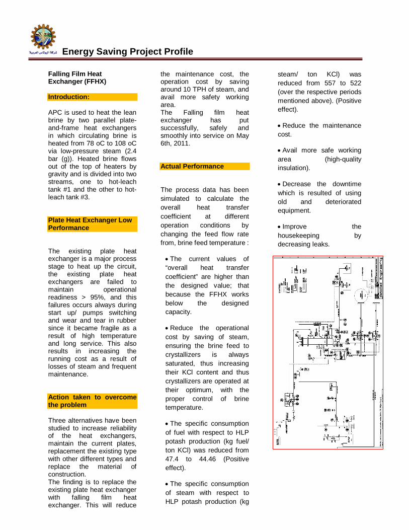
Falling Film Heat Exchanger (FFHX) Introduction: APC is used to heat the lean brine by two parallel plate-and-frame heat exchangers in which circulating brine is heated from 78 oC to 108 oC via low-pressure steam (2.4 bar (g)). Heated brine flows out of the top of heaters by gravity and is divided into two streams, one to hot-leach tank #1 and the other to hot-leach tank #3. Plate Heat Exchanger Low Performance The existing plate heat exchanger is a major process stage to heat up the circuit, the existing plate heat exchangers are failed to maintain operational readiness > 95%, and this failures occurs always during start up/ pumps switching and wear and tear in rubber since it became fragile as a result of high temperature and long service. This also results in increasing the running cost as a result of losses of steam and frequent maintenance.
Action taken to overcome the problem Three alternatives have been studied to increase reliability of the heat exchangers, maintain the current plates, replacement the existing type with other different types and replace the material of construction. The finding is to replace the existing plate heat exchanger with falling film heat exchanger. This will reduce
the maintenance cost, the operation cost by saving around 10 TPH of steam, and avail more safety working area. The Falling film heat exchanger has put successfully, safely and smoothly into service on May 6th, 2011. Actual Performance
The process data has been simulated to calculate the overall heat transfer coefficient at different operation conditions by changing the feed flow rate from, brine feed temperature :
The current values of “overall heat transfer coefficient” are higher than the designed value; that because the FFHX works below the designed capacity.
Reduce the operational cost by saving of steam, ensuring the brine feed to crystallizers is always saturated, thus increasing their KCl content and thus crystallizers are operated at their optimum, with the proper control of brine temperature.
The specific consumption of fuel with respect to HLP potash production (kg fuel/ ton KCl) was reduced from 47.4 to 44.46 (Positive effect).
The specific consumption of steam with respect to HLP potash production (kg
steam/ ton KCl) was reduced from 557 to 522 (over the respective periods mentioned above). (Positive effect).
Reduce the maintenance cost.
Avail more safe working area (high-quality insulation).
Decrease the downtime which is resulted of using old and deteriorated equipment.
Improve the housekeeping by decreasing leaks.

Energy Saving Project Profile
New Mineral Separator at HLP Introduction: APC product Handling area operates with various solids handling equipment, including bucket elevators, screw conveyors, screens, product cooler equipment, bins, etc.
The product at the exit of the dry is conveyed to the screening section where it is classified into different grades, i.e., standard, and fine, while part of standard, fines and dust are directed to the compaction unit where they are compacted to produce a granular product.
To achieve desired sizes of the fine and standard potash, dryer product is sieved and screened first in six parallel screens in which extra coarse particles are separated from the dried product. The remaining dryer product is sent to another six parallel secondary screens for further screening.
Reasons for APC to replace the existing screens: The old screens were built on 1982 with a capacity of 1.2 MMTPY, in 1987; HLP production capacity was increased from design Capacity of 1.2 to 1.4 MTPY and no modification has been carried out on the screening unit and till the time of replacement no major modification has been carried out on the screens
themselves to increase the capacity.
The most significant problem which has an adverse effect on the screens' performance is the critical condition of the frame, body and cover of the screens. The screens cover show signs of deterioration as a result of corrosion and erosion.
The high number of the used screeners and conveying equipments results in high consumption of power.
Action Taken Project alternatives have been studied, and a comparison between the proposed screens drawings and the field is carried out, the findings are: -
The main feed bins will replaced by two chutes.
Three main screw conveyers will be removed and use chute for fine material to fed fine bin.
Replace six primary screens model Rotex 81 and six secondary screens model 521 by two new screens mineral multi-deck screens model 4240-2 of a capacity of 135 TPH per each with their auxiliaries (chutes, magnetic separator, and automatic slide gates).
Process performance The main the performance is satisfactory; the physical analysis of standard potash is within the accepted rang; the difference between Tyler Mesh (10 - 65) is above 90%.
And up-to-date, the main achieved benefits are :-
Decrease the running cost of the screening units by decreasing the number of operated equipments such as screens and screw conveyers .
Decrease the down time which is resulted from using old and deteriorated equipment .
Improve the product quality by increasing the efficiency of the screens .
Obtain more free area .
Safe the environment by Improve the housekeeping by decreasing leaks .
Avail more safe working area.

Energy Saving Project Profile
Agriculture Run Off Water Collection System Introduction: Water is a major raw material in Potash production. A five and half-cubic meters of water is required to produce one ton of potash.
Environmental Problem: The local project area is an intensive farming area. Potash factories consume about 12 - 13 million m3/year. This high consumption uses up the good quality water on the account of farming and local community domestics’ uses. Reuse of agricultural run-off water in potash production will decrease good quality water consumption and protect the surrounding environment since this subsurface drainage water contains high percentage of chemical and biological pollutants. It forms local swamps, which affect surface and ground water and public health.
Action Taken Transfer the agriculture runoff water from there two main water sources near Safi to APC Plants’ and use it at HLP decomposition unit only. Process performance The outputs of the project are: - • Reducing fresh water consumption in Potash production by 2.4 million m3 per year.
• Using the recovered water from agricultural runoff water in potash production. • Improving local environment. • Preventing pollution of surface, and ground water by chemical pollutants.

Energy Saving Project Profile
Reduction of Transportation Fuel Diesel Introduction: APC owns and operates large number of different types and models of ground vehicles, which can be classified into two main categories :- •Passengers and general services: saloon cars, pickups, buses, tankers, service trucks and special equipment . •Potash Trucks: there are 94 heavy duty road trucks, they are equipped with diesel engine 6 cylinders in line, turbocharged and gear box is 10 forward speeds. Problem High consumption of diesel fuel oil. Solution Install a flat tilted sheet fitted on roof of the driver cabin, wind deflector in order to reduce overall drag. Replace the old trucks of 50 tons payload type MAC R612.ST and R688.S with 80 tons payload MAC type R612.ST to reduce the horse power consumption from 6.2 hp/transferred ton to 4.38 hp/transferred ton. Use a speed limiter to cut off the injection beyond a predetermined setting point Set a management program to follow up and average the fuel oil consumption per vehicle/type/model. Set a bounce formula that increase productivity and improve fuel efficiency without running vehicle fast especially on return trip.
Improve maintenance by carrying out schedule preventive maintenance. Replace the steel trucks trailer by Aluminum low tare weight trailers. These trailers, when put into operation this will allow 10 more Tons in the net tonnage per trip
Performance Evaluation: Less transportation costs due to :- Reduction in specific fuel consumption. Reduction in the daily trips . Less trucks' maintenance . Less accidents' possibility.
Saudi Fertilizer Co
SAFCO

Energy Saving studies conducted in SAFCO-2
Saudi Arabia Fertilizer Company (SAFCO) is committed to develop and use energy and water resources efficiently in providing products and services. SAFCO has the objective of reducing the site energy use by 10% by 2015 compared with the base year of 2010. This is part of the sustainability drive being implemented Worldwide by the SABIC group
A consultant was engaged by SAFCO to do carry out energy optimization study in SAFCO-2 ammonia and utility plants
The scope of study was as follows:
Evaluate present conditions of SAFCO II plants for energy / water consumption
Bench mark current plant energy figures thus achieved with Best Technology (BT) index
Identify improvement that can be achieved by non investment opportunities like overhauling of equipments/ operational
practices to achieve best possible performance
Identify improvement that can be achieved by investment opportunities for bridging identified gaps
Rough(+/-40%) installation cost for major investment opportunities
Prepare Feasibility Report containing the result of the above investigation to help SAFCO to select option(s) for the Project
The estimated study period was 4 months.
After award of the contract, the consultant visited the site, did a walkthrough exercise and collected all the necessary documents
Interim report was submitted after two month and final report was submitted after 4 months.
The study was done extensively completing the scope. SAFCO-2 ammonia plant was benchmarked with other plants and gap was analyzed in the following 4 areas:
1. Process design gap 2. Heat recovery gap 3. Fired heater gap 4. Power and Shaft work gap The majority of the gap was identified in power and shaft work gap due to many steam turbine drives being used As evaluated with R-curve , the direction of improvement is either increasing motor drive with more power import from SEC (Saudi Electric Corporation) or introducing gas turbine power generation with HRSG (Heat Recovery Steam Generator). As the power purchase price from SEC is expensive, the former direction would not be accepted by economic reason. Therefore the only remaining direction is gas turbine Based on the above, The consultant has submitted around 18 ideas which is suitable for reducing the energy reduction

Energy Saving studies conducted in SAFCO-2
Proposals Number Energy saving
High investment (GAS Turbine Proposals Electrical power generation) 9 0.8 to 8.1 %
Medium Investment 3 3.8 %
No/ low cost 6 1.2 %
Total Proposals 18 10
Since the majority of the proposals were gas turbine based, SAFCO did not consider to pursue the study further due to economic feasibility Replacement of S-200 to S-300 converter basket
SAFCO-2 ammonia plant was commissioned in 1993. Ammonia converter catalyst was not replaced so for. It is planned for replacement during April 2013 TA.. During the catalyst change, it was decided to replace the basket with S-300 type from the present S-200 type. Ammonia production is expected to increase by 4% with same energy input Study for conversion of CO2 removal system
Presently CO2 removal system in SAFCO-2, SAFCO-3 and Ibn Al Baytar is Hot Potassium carbonate. In IBB
the activator is ACT-1 and in SAFCO-2 and SAFCO-2 the DEA activator will be replaced with ACT-1 during coming TA. Study is being carried out by SABIC Technology and Innovation to convert this Benfield system to aMDEA in all the above 3 plants The study has been completed for SAFCO-2 and based on the report considering the low cost of energy in this region, it will not be economically feasible for this conversion. However it may be feasible if it is combined with debottlenecking projects. For other plants the study is under progress.

Petrochemical Industries Co.
PIC
Energy Saving Projects
Natural Gas Flash Separator Process Description: The Natural Gas supplied to PIC normally has 80% CH4, around 10% C2H6 and rest propane and heavy hydrocarbons. The molecular weight of this gas is around 20 and the pressure of supply is around 3.0 to 4.0 Kg/cm2g.
The gas is compressed in Natural Gas compressors to around 40 Kg/cm2g for processing in Ammonia plants. Natural gas compressor K 1301 is associated with Ammonia II plant and another Natural gas compressor K 3301 is associated with Ammonia IV plant. There is one more compressor K2301 as spare in Ammonia III, which can be lined up either to Ammonia IV or to Ammonia II. All these machines are 3 stage centrifugal compressors with inter-stage cooling and KO (Knock Out) drums for separation of condensate. Natural Gas (NG) loss Concern The density of the Natural gas fed to the plants is always not steady with fluctuations in molecular weight are experienced right from 17 to 28 Kg/Kg moles. The fluctuations are mainly due to injection of LPG in the NG header to maintain pressure during high demand instances. The total Natural gas flow handled in Ammonia II & IV plants are around
43000 Nm3/hr at a molecular weight of around 20 with an average loss of 1% of the total gas in compression. The condensate flow rate from the compressor was estimated as 2 tons/hr flow with 70% water and rest hydrocarbons.
The condensate collected in the inter-stage coolers and KO drums contains some slipped hydrocarbons as well some condensed hydrocarbons. Condensate from all the Natural Gas Compressors are collected in a 4" main drain header and sent to a ground flare “burning pit” at a pressure of 1.0 Kg/cm2g. Proposal Since the quantity of hydrocarbon lost in the compressor drains is significant, a study was conducted to recover these hydrocarbons. Also it becomes highly favorable at instances when LPG is injected in NG header. It is suggested to put a flash drum in the drain header where the hydrocarbon bearing condensate from the compressors would be flashed. The off gas from the flash drum will be recovered back in the Natural gas header feeding the boiler in Ammonia III plant, while the condensate with minimum hydrocarbons will be sent to the burning pit. Action Taken Whenever there is a case of high molecular weight NG,
condensation occurs in the higher compression stages. The analysis was done for a sample case, however depending upon the actual variation in the composition; the condensation can be more or less.
Out of line inter-stage separator of Refrigeration Compressor in line III was identified for re-use, as the design of this vessel is suitable to the operating condition. The adequacy of this drum was checked and the related Engineering works completed The tie-ins required to connect this flash separator to the existing system has been completed in November 2006 and the project was executed during June 2007 Actual Performance After implementing the project, the following befitted
1. Saving of 542 kg/hr of Hydrocarbons otherwise burnt in flare.
2. Reduction in CO2 emission.
3. Solving pollution problem associated with un-burnt hydrocarbons.
This project is attractive on the fact that no big capital investment is carried out and the existing separator is reused. The pay back for this project was less than 2 years.
Energy Saving Projects
Reduce Excess Oxygen in P lant B Boi lers and Super-heaters Excess Oxygen Concern
Plant B consists of Two Ammonia plants designed to produce 1880 M Ton of Ammonia and two Urea plants designed to produce 1400 M Ton of granulated urea. Four steam boilers and three super-heaters are serving plant B. In PIC quest of saving energy, six sigma project was implemented to reduce the excess oxygen from 4.8 % as an average to less than 3.5%.
Action Taken :
Six sigma started out by identifying Project stakeholders and devising a communication plan to optimize their benefit to the Project as well as their benefit from it. Seventy-eight possible root-causes were collected through brain-storming sessions. They were reduced to five probable root-causes through employing standard Six Sigma tools, including the evaluation chart and why-why methods. Corrective actions consisted of a developed Boilers’ APC Record Sheet to track changes and facilitate follow-up, developed a procedure to ensure Lab samples are taken at the same time and conducted awareness to operators on excess O2
Actual Performance:
After implementing the six sigma methodology, average excess oxygen reduced to 3.1% which resulted in 250,000 USD saving per year. Six sigma methodology was found to be effective in addressing defects in controlling excess oxygen and solving them systematically by targeting root-causes potentially contributing to the defect and devising effective corrective actions with continual improvement imbedded into them.
2
2.5
3
3.5
4
4.5
5
5.5
6
6.5Excess O2 % for Plant B Boilers and Superheaters
Befor After

Energy Saving Projects
Recovery of heat from the overhead vapors of Process Condensate Stripper
Description of system The boiler feed water in Ammonia II & III plants is fed to boilers through two de-aerators in series – vacuum de-aerator followed by thermal de-aerator. In the original design, 243 tons/hr of De-Mineralized (DM) water from vacuum de-aerator B6401 at 50oC is heated to 65oC in “Boiler Feed Water pre-heater after HPC regenerator” E2215 and subsequently to 84oC in “Boiler Feed Water heater before HPC absorber” E2212. As Ammonia III unit is not in line, heat is not available to heat DM water in E2215 and E2212. To compensate this loss, the outlet temperature of vacuum de-aerator is kept at 70°C instead of design 50°C. LP steam is used to heat the de-mineralized water to 105°C in thermal de-aerator. The steam supply valve to thermal de-aerator is full open. Also, Ammonia III boiler (H-2203) load is restricted to 110 MT/hr (instead of design 150 Mt/hr due to relatively cooler water temperature compared to design. In the utility section of Ammonia Plant, the process condensate is passed through “Process
Condensate Stripping Tower” F3501 where part of the ionic load from the condensate is reduced by stripping compounds like Ammonia, CO2, methanol, etc. In design conditions, around 60 tons of overhead gas is condensed from 94°C and cooled to 67 °C using 16 air coolers (8 fans) “Process Condensate reflux condenser” E3501 A-H and “after cooler” E3503. The total heat duty of these coolers is 21.6 MM Kcal/hr. Issue / Concern In actual operation, F3501 is being operated such that the vapor temperature at the top is 110°C which can be effectively used to heat DM water to boiler. Also all the fan coolers were not kept in line and it was found by experience, 1 or 2 out of 8 fans can be switched off depending on ambient condition during normal plant load condition. Action taken: A study was conducted for heating the DM water to Ammonia III thermal de-aerator using the heat in the overhead vapors of the Process Condensate stripper F3501. The proposal is to introduce a shell and tube exchanger upstream of air coolers before air coolers to recover the heat in DM water. The advantages will be - Reduce steam consumption in thermal de-aerator.
- Recover heat rejected in air for heating DM water. - Stop some of the air coolers to save power. - Ease the bottleneck of Ammonia III boiler due to low BFW temperature. Instead of buying a new heat exchanger, E-2212 that is not in line in Ammonia III plant was used for this purpose. The design heat duty of E-2212 is 5.2 MM Kcal/hr and it has been designed to handle gas in shell and DM water in tube. The design pressure for this heat exchanger is 26 Kg/cm2g in shell and 3.5 Kg/cm2g in tube. The design operating temperature is 125 °C in shell and 80°C in tube. The profile of this exchanger is more suitable for this application. Actual Performance After implementing the project, the following befits were achieved:- Considerable saving in capital expenditure that otherwise would have been spent to replace the leaking bundles of E3501 Minimum project cost due to reuse of old heat exchanger which otherwise would have been scrapped. Lower CO2 generation from boiler due to less firing of fuel equivalent to energy saved. The payback period for the project was 1.36 years.

Energy Saving Projects
Installation of heat exchanger to improve heat recovery from HPC regenerator Overhead gases: Description of the System In Ammonia II plant, CO2 leaving the top of “HPC regenerator” F 1207 is cooled in a series of exchangers before being sent to Urea plant for urea production. In design, the first heat exchanger is “Boiler Feed Water Pre-heater after HPC regenerator” E1215, where the gas is cooled from a temperature of 102 °C to 88 °C while DM water feed to boiler is heated up from 50 °C to 65 °C. The CO2 gas passes on to subsequent cooler “HPC regenerator overhead cooler” E 1216 A/B for further cooling with fresh cooling water. Like in Ammonia III, the boiler feed water to E 1215 is supplied from “vacuum de-aerator” B-6401 A. Water after getting heated up in E 1215 and subsequently in “BFW Pre-heater before HPC Absorber” E 1212 reaches thermal de-aerator B 1216 for removal of oxygen. Issues / concerns In order to supply the thermal de-aerator with high temperature water, the temperature outlet of vacuum de-aerator is kept much above the design temperature of 50°C. This combined with the fact that the regenerator is being operated at 0.6 Kg/cm2g instead of 0.15 kg/cm2g forces operation of E 1215 shell side at higher temperature. However, this
condition increases the temperature of CO2 gas leaving Ammonia II plant to 65 °C instead of design 45 °C.
Proposal to overcome the concerns As the Ammonia III line is no longer in operation, the idle E2215 in Ammonia III can be shifted and installed in parallel to E1215 in Ammonia II. The benefit would be not only in reducing the CO2 gas temperature at the outlet of Ammonia II battery limit, but also increasing the feed water temperature to thermal de-aerator. The thermal and hydraulic performance of the system was simulated to assess the impact of the modification on the plant and to evaluate the extent of energy recovery. The findings of thermal-hydraulic study of shifting E2215 in parallel to E1215 are summarized below
With DM water at 50°C, operating E2215 in parallel to E1215 increases the DM water temperature to 68.7°C as against 64.55°C with one exchanger. The shell gas temperature will be slightly reduced, but condensation of moisture is increased to 10838 kg/hr from 8367 kg/hr. The heat gained in DM water increased from 4.75 MM kcal/hr to 6.4 MM kcal/hr.
The increase in pressure drop estimated due change in gas piping configuration is negligible
Action Taken Based on the above analysis, it was decided to install E2215 in parallel to E1215 and connect the boiler feed water in series from one heater to the other. Actual Performance After implementing the project, the following benefits were achieved:- : Minimum project cost due
to reuse of old heat exchanger which otherwise would have been scrapped.
Lower CO2 generation from boiler due to less firing of fuel equivalent to energy saved. The payback for the project was 0.35 years. This pay back was calculated not considering the improvement in CO2 compressor performance due to lower suction temperature.
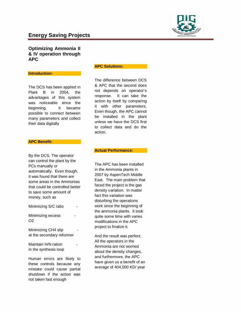
Energy Saving Projects
Optimizing Ammonia II & IV operation through APC Introduction: The DCS has been applied in Plant B in 2004, the advantages of this system was noticeable since the beginning. It became possible to connect between many parameters and collect their data digitally
APC Benefit:
By the DCS, The operator can control the plant by the PCs manually or automatically. Even though, it was found that there are some areas in the Ammonias that could be controlled better to save some amount of money, such as
- Minimizing S/C ratio
- Minimizing excess O2
- Minimizing CH4 slip at the secondary reformer
- Maintain H/N ration in the synthesis loop
Human errors are likely to these controls because any mistake could cause partial shutdown if the action was not taken fast enough
APC Solutions:
The difference between DCS & APC that the second does not depends on operator’s response. It can take the action by itself by comparing it with other parameters. Even though, the APC cannot be installed in the plant unless we have the DCS first to collect data and do the action.
Actual Performance:
The APC has been installed in the Ammonia plants in 2007 by AspenTech Middle East. The main problem that faced the project is the gas density variation. In matter fact this variation was disturbing the operations work since the beginning of the ammonia plants. It took quite some time with varies modifications in the APC project to finalize it.
And the result was perfect. All the operators in the Ammonia are not worried about the density changes, and furthermore, the APC have given us a benefit of an average of 404,000 KD/ year

Energy Saving Projects
Energy Conservation by reducing plant shutdown and production curtailment by replacing Urea Plant-A Stripper Urea Plant-A Stripper performance and corrosion issues
PIC Urea Plant-A originally based on Stamicarbon Conventional Total Solution Recycle Process was revamped in the Year 2002 to increase plant production by adding Stripper and Pool Condenser and retaining most of the equipment in other sections of the plant. But during commissioning, it was found that Stripper was not performing as per design intent and the plant could not be operated more than 90% load for nearly two years. But after installing some additional equipment and modifying plant operating conditions in Nov 2004, the plant could be operated at 100% load. But there was no margin in plant operation at the design load.
Apart from performance issue, Stripper caused severe production curtailment due to load reduction and unscheduled outages due to abnormal corrosion of the tubes. Stripper was inspected first in Nov 2014 after nearly two years in operation. A few tubes were found with abnormal corrosion rates and the same were plugged. However during subsequent Stripper inspections it was found that more and more tubes were showing signs of very high corrosion rates and these defective tubes were plugged preventively.
After 10 years in operation, nearly 5% of the tubes were plugged. The plugging of more and more tubes affected stripping efficiency and consequently Stripper became a major bottleneck for plant production. Plant could not be operated more than 95%. Stripper was no longer reliable due to inexplicable & unpredictable corrosion phenomena.
Stripper was made of BC.05 material and it was designed to operate at higher pressure and temperature compared to Stamicarbon conventional Stripping Process. Due to corrosion of Stripper tubes, nickel in product started increasing from 0.3 ppm in year 2002 to nearly 0.5 ppm in year 2012.
Action Taken:
Root Cause Analysis of the Stripper tube failure was carried out independently both by PIC and Stamicarbon but the root causes of the problem could not be corroborated by validation. Hence it was decided to replace BC.05 Stripper with new Safurex Stripper with 5% more heat transfer area in order to get over the corrosion problem and improve Stripping efficiency marginally to provide more operating margin at design throughput.
Accordingly defective BC.05 Stripper was removed and the new Safurex Stripper was installed in the same location during planned shutdown for turnaround activities in March 2012.
Actual Performance: After installation of the new Stripper in March 2012, the plant was restarted in April 2012. With new Stripper in operation, nickel in product reduced from 0.5 ppm to less than 0.25 ppm. Stripping efficiency improved by 2% providing significant margin for plant operation. As a result plant load could be increased by 1-2%. There were no outages due to Stripper during last one year. The new Stripper will be inspected during next plant turnaround in Nov 2014.

Energy Ef f ic iency in the Phosphate Industry: The case of HRS System in OCP Group R. EL MRABET & K. SAOUD E-M ai l : r . elmrabet @ocpgroup.ma
Phone : +212 661 45 24 48 OCP Group, Morocco Cost leadership: The Group has targeted a 30%-40% reduction of its costs. By improving its productivity and industrial processes, the OCP Group is targeting a 30%-40% cost reduction. A major contribution will come from the energy efficiency. This article treats an example: the increase of the amount of heat recovery from the lines of sulphuric acid production at OCP sites.
The purpose of the project is to increase the amount of heat recovery, in the form of steam, from the lines of sulphuric acid production at OCP site of Jorf Lasfar, in order to generate a greater amount of steam, leading to a greater on-site power generation. The project activity involves the replacement of the existing intermediary absorption towers by a Heat Recovery
System (HRS). The new HRS will lead to a significant increase of the heat recovery ratio, i.e. the ratio between the heat recovery and the released heat by exothermic reactions in the process. The steam will be produced by the HRS and be mixed with the existing steam recovered in the production process. The excess steam delivered from
the acid plants to the steam turbine generators enables OCP to generate more power than required for internal needs. The amount of sulphur used to generate the excess steam will remain constant in the project activity, as compared to the
current situation.
As a result, the additional recovered heat from the proposed project activity will
lead to:
reduce calls of power from ONEE (Moroccan local supplier of electricity);
reduce cost of energy
promote processes such as desalination of seawater
The project is considered as an example of promoting sustainable development at
OCP Group because :.
It uses clean and efficient technologies, and preserves natural resources;
It acts as a clean technology demonstration project.
Beside environmental considerations, the project will improve the competitiveness of OCP and reduce Morocco’s fossil resources importation, leading to net benefits for the
economy of the country. Technology to be employed by the project activity
The project activity involves the retrofit of existing sulphuric acid production lines. The replacement of the current intermediary
absorption towers of production lines by HRS
systems.
The retrofit implies the installation of two HRS systems together with their tanks and pumps, a steam boiler, water pre-heater, a dilution device, pumps for the water supply and for acid emptying, and the monitoring instrumentation, for a 20
million US$ total investment.
The heat recovery system is basically an absorber that uses a boiler to remove the absorption heat as steam, instead of acid coolers
(where heat is wasted).
This new type of tower is characterised by a high temperature of the gases at the exit, which allows the generation of additional saturated steam, and leads to a greater ratio between the recovered heat and the released heat by the exothermic absorption process. Currently, 70% of the released heat by the process is recovered, while 28% are evacuated in the cooling water pumped from the sea, and 2 % is lost by radiation. The new installation will lead to 50 tons per hour of additional saturated steam at medium pressure (9.5 bars). Due to its saturated state, this steam cannot be expanded in the
existing turbine. However, it substitutes steam currently extracted from the turbine for process needs, allowing the full expansion of a greater amount of steam. About 8 MW of additional power per unit can therefore be generated at nominal capacity of acid production, totalling 16 MW for the two units to be installed by the
proposed project activity.

Figure .1 presents a simplified scheme of the energy management at OCP chemical sites
Figure .2 presents a simplified flow scheme of the technology. The heat recovery system is basically an
absorber that uses a boiler to remove the absorption heat as steam, instead of acid coolers (where heat is
wasted).

FERTIL Co.

Energy Saving Project Profile
Hydrogen Recovery Unit The first phase of energy conservation measures started in 1989 with installation of Hydrogen from the purge gas. The unit is based on cryogenic separation of hydrogen which was recycled back to the
synthesis loop. Till then, the purge gas was burnt as fuel in the reformer. This measure alone reduced specific energy consumption by 0.15-0.25 GCal/MT of ammonia and the rated Ammonia Production capacity increased from 1000MTPD to 1050 MTPD
The old tubes completed 116,000 operating hrs and material was IN519 (24%Cr, 24%Ni), tubes replaced with improved HP material (KHR35CT by KUBOTA of Japan) in 1998. The new metallurgy had higher strength and it was possible to use thinner wall tubes for the same operating condition of temperature in the reformer. New tubes have bigger inside diameter which
accommodated 24% extra volume and allowed increased throughput. This not only increased the reformer capacity but also helped to save energy consumption. 2nd replacement: The reformer tubes were changed once again in the turnaround of 2012 to increase and improve the reformers performance
Secondary reformer and Transfer line
Hot spots appeared in secondary reformer due to cracks in refractory.
In 1998 it was replaced with new vessel with upgraded material of 1 1/4 Cr, 1/2Mo, (previous was 1/2Mo, C).
In 2001 the transfer line was replaced with the same upgraded material and due to hotspots.
Ammonia Converter basket/ catalyst replacement: The ammonia synthesis catalyst had completed 15 years of service in 1998 so it was replaced and a new modified basket installed.
The empty space at the inter-bed exchanger was utilized to pack in extra catalyst. The new S-200 basket resulted in lower syn loop pressure and hence lower syn gas compressor power consumption. Plant load was also increased.
Improvement in CO2 Removal unit (Benfield Process): DEA activator was replaced by ACT-1 activator resulting in reduction of 12 MT/hr low pressure steam earlier used for regeneration, consequently 15% duty on top condenser reduced. Filtration improved by adding one more filter and using 5 & 1 microns elements. High efficiency demisters, modified wash trays, IMTP packing in Absorber and Regenerator used. So, Potash carryover, wash trays fouling stopped and chemical consumption reduced.
FERTIL was the first process plant to have DCS control system in the gulf and the Middle East. The up gradation of the system was justified by:
82% of plant trips were due to false actuation of field switches, trip bypass switches, TDC 2000 box failure, shutdown and letdown valves.
Ageing of individual components and unavailability of spare parts from vendors.
Difficulties in trouble shooting of the shutdown or diagnosing the spurious and momentary trips.
The change was carried out in the following phases:
The upgradation of Honeywell TDC 2000 & 4500 computer system to TDC 2000 & TDC 3000LCN system was the first phase of DCS upgradation to solve the problem of 4500 computer obsolescence.
Upgradation of TDC 2000 basic controllers to TDC 3000- Advanced Process Managers (APM) based UCN devices was the phase 2 of DCS upgradation to bring in higher reliability to control system.
Upgradation of electromagnetic emergency shutdown system to the triple modular redundant, fault tolerant Triconex PLCs with voting system for field transmitters and safety manager module (SMM) to integrate DCS and ESD is the part of continuous upgradation of control system for higher safety, availability and reliability.
Advanced Process Control (APC) was installed to control the Primary reformer outlet temperature.

Energy Saving Project Profile
Since the implementation of the above system in
1998, not a single plant Trip due to spurious
instrument fault has occurred till date.
Upgradation of high pressure Boiler &
medium pressure Boiler ESDs and
control system to Honeywell -Total Plant
Solution (TPS) - was carried out during
T/A 2001 to keep up with the latest
technology.
Upgradation of CO2 compressor anti
surge control systems and replacement
of central control room TDC 3000 -
universal stations and mimic panels by
Honeywell - Global User Stations and
EST (plasma screens) during T/A 2005.
Honeywell with PKS Experion with HPM
Controllers & EST (with plasma
screens) was provided in 2005.
Modifications were implemented in
interlock logic circuit of ESD system for
quicker recovery from process upsets.
Urea Debottlenecking Project (UDP):
Urea Debottlenecking Projects was implemented
in October 2009 to convert all surplus Ammonia
to Urea with the scope to increase Urea Plant
capacity, as follows:
Modifications to the existing urea plant
was carried with introduction of medium
pressure section to convert surplus
ammonia thus increasing the capacity of
urea plant to 2300 MT granular urea per
day. Synthesis section has being
designed for a capacity of 2700 MT of
urea solution
Installation of a 400 MTPD CO2
recovery plant from presently vented
flue gases of the ammonia plant. This
also resulted in appreciable reduction in
GHG emissions.
Installation of a new 2500 MTPD
Granulation unit. Urea dust emissions
were reduced remarkably with this and
at the same time achieving more
uniform product.
Primary Reformer Integrity
enhancement:
Project Rationale:
The objective in the selection of various parts of
reformer in the replacement opportunity was to
increase energy conservation to conserve
resources and enhance plant throughput,
without jeopardizing plant reliability and safety.
Following Integrated activities related to Primary
reformer were planned to achieve the above
objectives:
1) Replacement of Refractory with
improved material for energy saving
2) Replacement of Refractory Insulation
with more fire resistant material
Insulation
3) Availing the opportunity of convection
coils and reformer tubes replacement
due to ageing, loading of new improved
catalyst with less pressure drop
Performance Enhancement
Reformer furnace casing skin temperature with
original refractory (material LBK23) was 75°C.
The modification of installing improved refractory
material (LBK26) resulted in casing temperature
reduction to 65°C.
Heat loss reduction from side wall is 225
KCal/m2-hr which is equivalent to 0.21%
reduction in fired duty. Primary reformer fuel
consumption has been remarkably reduced.
Now specific gas consumption is 1% less than
before Turnaround and amount to annual saving
of US$ 80,000.
Presently, Primary reformer flue gas exit
temperature is 240°C, which is 60°C less than
before all these modifications.
Improved furnace efficiency of radiant and
convection section are the key factors in
achieving this low value of flue gas exit
temperature.
By opting latest Primary Reformer catalyst,
reformer tubes pressure drop has reduced
significantly. Present equalized pressure drop
across reformer tubes is 0.35 kg/cm2 less than
the previous.
Moreover, pressure drop across new coils is
less leading to higher throughput. Plant is now

Energy Saving Project Profile
operating above 100% load (102.5%)
consistently. Pressure drop improvement in
catalyst tubes and convection coils is major
contributing factor in achieving higher load.
With the reduction in front end pressure drop,
natural gas compressor power consumption has
also reduced.
Compressor is now operating 1.8 kg/cm2 less
discharge pressure than before turnaround that
is equivalent to 20% less power consumption.
Previous power consumption was 1500 KW
which is now brought down to 1250 KW.
Project Evaluation
The energy saving after adopting new type of
refractory, new type of catalyst along with new
tubes and convection coils in the Primary
reformer is significant. Gains achieved can be
summarized as follows:
1% reduction in fuel consumption of
Primary Reformer (equivalent to US$
80,000 annual saving)
Significant contribution in reducing
reformer flue gas exit temperature (300
to 240°C)
10°C reduction in Reformer wall skin
temperature
0.35 kg/cm2 reduction in Reformer
tubes pressure drop
1.8 kg/cm2 reduction in Natural Gas
Compressor discharge pressure
20% reduction in compressor power
consumption